Embed Size (px)
Citation preview

Perfluoroelastomer and Fluoroelastomer Seals for Photovoltaic Cell Manufacturing Processes
Technical Information — Rev. 1, July 2010 Paper presented at InterSolar SMET, May 2009
Photovoltaic (PV) cell manufacturing involves the use of many aggressive chemicals and operates under very severe environments, including high temperatures and reactive plasma. As more aggressive processing variants and technologies are used to help increase equipment uptime and cell efficiency, more strain is placed on the manufacturing process. Sealing performance can vary dramatically; thus selecting the appropriate sealing material can help reduce unscheduled downtime, product loss and safety concerns to the work environment.
Perfluoroelastomers and fluoroelastomers are widely used as seals in PV cell manufacturing equipment due to their extraordinary resistance to chemicals and heat. The first commercial perfluoroelastomer was developed in 1968 by E.I. duPont de Nemours. It was sold as parts (seals) under the trade name DuPont™ Kalrez®. The first commercial fluoroelastomer was produced by E.I. duPont de Nemours in 1957. It was sold under the tradename DuPont
sed in
r of
e cases, seal
me
s y to
re used in many high
er to
ading to problems during pump-down or causing toxic gases to be released into the atmosphere.
™ Viton® (Viton® A). From this beginning, the use of perfluoroelastomers and fluoroelastomers has increased steadily as application requirements have become more stringent. Today, perfluoroelastomer and fluoroelastomer seals are manufactured by a number of companies worldwide including DuPont.
The purpose of this paper is to provide application guidelines for the selection of sealing materials uaggressive PV cell manufacturing processes. Test results will highlight the performance of various fluorinated elastomers in typical PV processing environments. There are three major types of processing applications in PV cell manufacturing: wet chemistry, high temperature and reactive plasma. A numbeprocessing steps involve the use of wet chemistry. Many of these steps utilize aggressive acids and bases for etching or cleaning. For example, hot KOH is used for surface texturing of crystalline silicon wafers. Aggressive chemicals can degrade elastomeric seals leading to seal failure. In somfailure can lead to contamination of the process and also cause safety incidents to occur.
In addition to “wet” applications, test results in high temperature applications such as doping in crystallinesilicon and diffusion in CIGS are discussed. Exposure to high temperatures can cause seals to becohard and brittle, thereby losing their ability to maintain effective sealing. Elastomeric seals can also degrade under high temperatures causing outgassing to occur. Hydrofluoric acid (HF) is one of the gaseevolved when FFKM and FKM begin to degrade. It can be harmful to process equipment, especiallquartz and stainless steel components. Additionally, aggressive chemicals atemperature PV processes which further complicates the material choice.
ZnOx reactive sputtering for back and front contacts and fluorine-containing plasma for PECVD chambcleaning (ARC and u-Si layer deposition) are examples of processes where seals can be exposedreactive plasma. Plasma can be a very aggressive media depending on the power and chemistry employed. If not selected appropriately, elastomers can be eroded at an astonishing rate in plasma, le

Test results will highlight the weight loss properties of various fluorinated elastomers and silicone as result of exposure to oxygen and fluorine-based plasma. A relative comparison of the various types of perfluoroelastomers as well as a comparison to other elastomeric materials is also presented and discussed.
Structure and Properties of Perfluoroelastomers and Fluoroelastomers Elastomers or rubber-like materials are made of long randomly coiled flexible macromolecules that allow the polymer to undergo large deformation upon stretching or compression. In addition, a crosslinking structure between the polymer chains provides a permanent three-dimensional network that ensures recovery. A schematic view is shown below.
Polymer Backbone Structure The most commonly used elastomers in the Photovoltaic (PV) Industry are fluorinated and perfluorinated elastomers, silicone (VMQ) and fluorosilicone (FVMQ). Fluorinated elastomers contain either a partially or fully fluorinated backbone. If the backbone is fully fluorinated, it is a perfluoroelastomer (FFKM); if it is partially fluorinated, it is a fluoroelastomer (FKM). The polymer backbone is comprised of many repeating monomer units. Typical monomer units for these polymers can be found below.
FFKM
FKM

FVMQ
VMQ
The carbon-fluorine bond is the most stable single bond. The high bond dissociation energy of the C-F bond is the main reason for the thermal, oxidative and chemical stability of fluorinated polymers. Table 1 lists the typical bond dissociation energies of single bonds. Homo-polytetrafluoroethylene (PTFE) contains all C-F substitution, which makes it one of the most chemically and thermally stable polymers. However, PTFE has very high crystallinity. As a result, it is a rigid thermoplastic, not an elastomer. Randomly incorporating other monomers into homopolymers breaks the regularity and forms amorphous polymers with a low glass transition temperature. Perfluoromethylvinyl ether (PMVE) and other perfluoro (alkoxy/alkyl) vinyl ethers are the monomers that are incorporated with TFE monomer in most commercial perfluoroelastomers. If other partially fluorinated monomers are incorporated, it forms fluoroelastomers. One of these partially fluorinated monomers is vinylidene fluoride (VF2). The most widely available fluoroelastomers generally contain two or three monomers. The building blocks of fluoroelastomers are listed in Table 2. Using these fluoro-monomers, four basic FKM structures can be made as shown in Table 3.
Table 1. Typical Bond Dissociation Energies for Aliphatic Bonds (KJ/mol) C-C 284–368 C-H 381–410 C-Cl 326 C-F 452 C-O 350–389 C-N 293–343

Table 2. Building Blocks of Fluoroelastomers TFE Tetrafluoroethylene
PMVE Perfluoromethylvinyl Ether HFP Hexafluoroproplyene VF2 Vinylidene Fluoride
CSM Cure Site Monomer
Table 3. Examples of Commercial Fluoroelastomer Structure Fluoroelastomer Type Monomer Sequence Example
Copolymer VF2-HFP Fluoroelastomer-A (66%F) Terpolymer VF2-HFP-TFE Fluoroelastomer-B (68%F)
Tetrapolymer VF2-HFP-TFE-CSM Fluoroelastomer-GF (70%F) Tetrapolymer VF2-PMVE-TFE-CSM Fluoroelastomer-GFLT (67%F)
Crosslinking Structure In order for a material to be rubber-like, polymers having a three-dimensional network structure are essential. For perfluoroelastomers, due to the inertness of the perfluorinated backbone, a cure site monomer (CSM), such as a monomer that contains a reactive site is introduced. The CSM can then react to form a three-dimensional network. The most significant CSM for FFKMs are cyano-functional vinyl ethers. The major advantage of using these CSMs is that they can be effectively cured using a variety of curatives. For example, curing with tetraphenyl tin or ammonia results in a triazine crosslink structure as shown in Figure 1. Use of the di-functional curative diaminobisphenol AF results in condensation to form a benzoxazole crosslink as shown in Figure 2. These resulting networks have excellent thermal stability. Cyano-functional vinyl ethers can also be cured using organic peroxide with the resulting network having near universal chemical resistance. In addition, halogens are other common CSMs for FFKM which are readily crosslinked using peroxide-based curatives. The major disadvantage of peroxide curing FFKMs is the hydrocarbon nature of the crosslink, which is much more susceptible to oxidative and thermal degradation.
There are three main cure chemistries for fluoroelastomers. Bisphenol and diamine are used mainly for VF2 and HFP containing polymers. They are the most common FKMs. Specialty FKMs containing a halogen as a CSM are peroxide curable. Fluoroelastomer properties such as heat and chemical resistance, low temperature flexibility, resistance to steam and acids and compression set resistance can vary considerably depending on monomer composition, concentration and the cure chemistry employed.
Figure 1. Triazine Crosslink Structure
N
N
N
F2C
CF2CF2
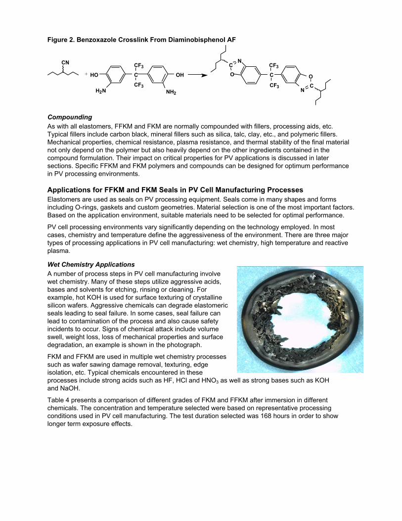
Figure 2. Benzoxazole Crosslink From Diaminobisphenol AF
C OH
NH2
HO
H2N
CF3
CF3
CN NCO C
NCO
CF3
CF3
+
Compounding As with all elastomers, FFKM and FKM are normally compounded with fillers, processing aids, etc. Typical fillers include carbon black, mineral fillers such as silica, talc, clay, etc., and polymeric fillers. Mechanical properties, chemical resistance, plasma resistance, and thermal stability of the final material not only depend on the polymer but also heavily depend on the other ingredients contained in the compound formulation. Their impact on critical properties for PV applications is discussed in later sections. Specific FFKM and FKM polymers and compounds can be designed for optimum performance in PV processing environments.
Applications for FFKM and FKM Seals in PV Cell Manufacturing Processes Elastomers are used as seals on PV processing equipment. Seals come in many shapes and forms including O-rings, gaskets and custom geometries. Material selection is one of the most important factors. Based on the application environment, suitable materials need to be selected for optimal performance.
PV cell processing environments vary significantly depending on the technology employed. In most cases, chemistry and temperature define the aggressiveness of the environment. There are three major types of processing applications in PV cell manufacturing: wet chemistry, high temperature and reactive plasma.
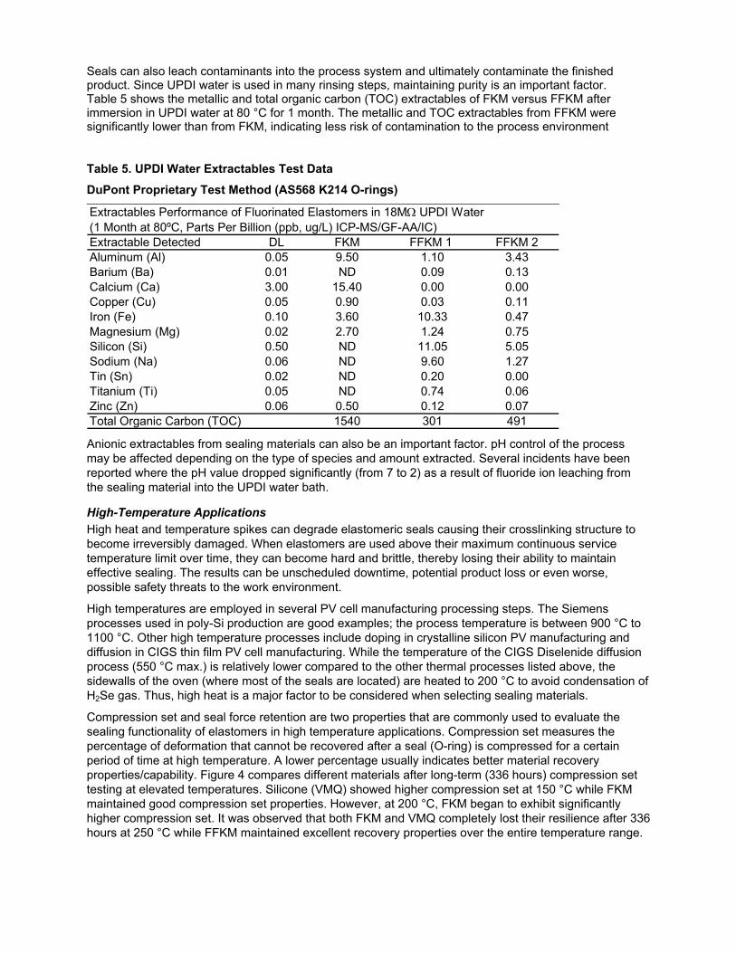
Wet Chemistry Applications A number of process steps in PV cell manufacturing involve wet chemistry. Many of these steps utilize aggressive acids, bases and solvents for etching, rinsing or cleaning. For example, hot KOH is used for surface texturing of crystalline silicon wafers. Aggressive chemicals can degrade elastomeric seals leading to seal failure. In some cases, seal failure can lead to contamination of the process and also cause safety incidents to occur. Signs of chemical attack include volume swell, weight loss, loss of mechanical properties and surface degradation, an example is shown in the photograph.
FKM and FFKM are used in multiple wet chemistry processes such as wafer sawing damage removal, texturing, edge isolation, etc. Typical chemicals encountered in these processes include strong acids such as HF, HCl and HNO3 as well as strong bases such as KOH and NaOH.
Table 4 presents a comparison of different grades of FKM and FFKM after immersion in different chemicals. The concentration and temperature selected were based on representative processing conditions used in PV cell manufacturing. The test duration selected was 168 hours in order to show longer term exposure effects.

Table 4. Chemical Immersion Test Data
Testing Performed per ASTM D471 and D1414 (AS568 K214 O-rings)
Chemical Property FKM FFKM1 FFKM2% Volume Change 10.1 1.6 13.1
Points Hardness Change (Shore A) -6 -1 -2% Change in Ultimate Tensile Stress 62.4 -0.9 -7.4
% Change in Total Elongation -37.4 -12.0 -22.9% Volume Change 29.8 1.8 3.8
Points Hardness Change (Shore A) -54 -6 -12% Change in Ultimate Tensile Stress -43.4 -5 -9.7
% Change in Total Elongation -77.3 -31.3 -58.8% Volume Change -20.7 -0.1 -0.3
Points Hardness Change (Shore A) -5 1 0% Change in Ultimate Tensile Stress 11.5 -12.5 -2.8
% Change in Total Elongation -62.6 -7.6 1.2% Volume Change 66.9 0.3 -0.5
Points Hardness Change (Shore A) 0 0% Change in Ultimate Tensile Stress -14.3 -5.1
% Change in Total Elongation -19.2 -5.5
O-rings brittle and cannot
be measured
HF (49%) @ 80°C For 168 Hours
NaOH (60%) @ 80°C For 168 Hours
HNO3 (60%) @ 80°C For 168 Hours
KOH (30%) @ 80°C For 168 Hours
Significant performance differences were observed between FKM and FFKM. Generally speaking, FFKMs tend to exhibit better resistance to chemical attack from strong acids and bases, suggesting potentially longer seal life. For example, in a 30% KOH exposure test at 80°C, the FFKM materials tested showed minimal change in properties while the FKM material had a volume change of more than 60%. In addition, the FKM test specimens embrittled and could not be measured for hardness and retained physical properties.
The comparison also demonstrates that performance variation can exist within the same elastomer category. In 49% HF exposure testing at 80 °C, FFKM1 exhibited significantly lower volume swell and had better retention of mechanical properties versus FFKM2. As a result, FFKM1 should be preferentially selected over FFKM2 for applications where HF is used.
Temperature also plays a significant role in the aggressiveness of various chemicals. For example, Figure 3 illustrates the effect of temperature on different FFKM grades when immersed in hydrofluoric acid. The volume change rate increased significantly as the temperature was increased from 25 °C to 50 °C.
Figure 3. Volume Change in Hydrofluoric Acid as a Function of Temperature
Testing Performed per ASTM D471 and D1414 (AS568 K214 O-rings)
Hydrofluoric Acid (50%) Immersion Test315 Hours at 25ºC, then 72 Hours at 50ºC
-0.5
0
0.5
1
1.5
2
2.5
3
3.5
4
0 50 100 150 200 250 300 350 400
Time (Hrs)
Vol
ume
Cha
nge
(%) FFKM 1
FFKM 2FFKM 3
50°C
25°C
Seals can also leach contaminants into the process system and ultimately contaminate the finished product. Since UPDI water is used in many rinsing steps, maintaining purity is an important factor. Table 5 shows the metallic and total organic carbon (TOC) extractables of FKM versus FFKM after immersion in UPDI water at 80 °C for 1 month. The metallic and TOC extractables from FFKM were significantly lower than from FKM, indicating less risk of contamination to the process environment
Table 5. UPDI Water Extractables Test Data
DuPont Proprietary Test Method (AS568 K214 O-rings)
Extractables Performance of Fluorinated Elastomers in 18MΩ UPDI Water (1 Month at 80ºC, Parts Per Billion (ppb, ug/L) ICP-MS/GF-AA/IC)Extractable Detected DL FKM FFKM 1 FFKM 2Aluminum (Al) 0.05 9.50 1.10 3.43Barium (Ba) 0.01 ND 0.09 0.13Calcium (Ca) 3.00 15.40 0.00 0.00Copper (Cu) 0.05 0.90 0.03 0.11Iron (Fe) 0.10 3.60 10.33 0.47Magnesium (Mg) 0.02 2.70 1.24 0.75Silicon (Si) 0.50 ND 11.05 5.05Sodium (Na) 0.06 ND 9.60 1.27Tin (Sn) 0.02 ND 0.20 0.00Titanium (Ti) 0.05 ND 0.74 0.06Zinc (Zn) 0.06 0.50 0.12 0.07Total Organic Carbon (TOC) 1540 301 491 Anionic extractables from sealing materials can also be an important factor. pH control of the process may be affected depending on the type of species and amount extracted. Several incidents have been reported where the pH value dropped significantly (from 7 to 2) as a result of fluoride ion leaching from the sealing material into the UPDI water bath.
High-Temperature Applications High heat and temperature spikes can degrade elastomeric seals causing their crosslinking structure to become irreversibly damaged. When elastomers are used above their maximum continuous service temperature limit over time, they can become hard and brittle, thereby losing their ability to maintain effective sealing. The results can be unscheduled downtime, potential product loss or even worse, possible safety threats to the work environment.
High temperatures are employed in several PV cell manufacturing processing steps. The Siemens processes used in poly-Si production are good examples; the process temperature is between 900 °C to 1100 °C. Other high temperature processes include doping in crystalline silicon PV manufacturing and diffusion in CIGS thin film PV cell manufacturing. While the temperature of the CIGS Diselenide diffusion process (550 °C max.) is relatively lower compared to the other thermal processes listed above, the sidewalls of the oven (where most of the seals are located) are heated to 200 °C to avoid condensation of H2Se gas. Thus, high heat is a major factor to be considered when selecting sealing materials.
Compression set and seal force retention are two properties that are commonly used to evaluate the sealing functionality of elastomers in high temperature applications. Compression set measures the percentage of deformation that cannot be recovered after a seal (O-ring) is compressed for a certain period of time at high temperature. A lower percentage usually indicates better material recovery properties/capability. Figure 4 compares different materials after long-term (336 hours) compression set testing at elevated temperatures. Silicone (VMQ) showed higher compression set at 150 °C while FKM maintained good compression set properties. However, at 200 °C, FKM began to exhibit significantly higher compression set. It was observed that both FKM and VMQ completely lost their resilience after 336 hours at 250 °C while FFKM maintained excellent recovery properties over the entire temperature range.

Figure 4. Long-Term Compression Set Test Data
Testing Performed per ASTM D395B and D1414 (AS568 K214 O-rings)
Long term compression set testing after 336 hours
0
20
40
60
80
100
FFKM FKM VMQ
%
150°C 200°C 250°C
O-ring Lost R
esilience
O-ring Lost R
esilience
Long term compression set testing after 336 hours
0
20
40
60
80
100
FFKM FKM VMQ
%
150°C 200°C 250°C
O-ring Lost R
esilience
O-ring Lost R
esilience
Seal force retention measures how much contact pressure a seal can maintain after exposure to high temperature over an extended period of time. Figure 5 compares the seal force retention properties (% sealing force retained) of various materials at 204 °C. Again, significant performance variation was observed between FFKM, FKM and VMQ.
Figure 5. Seal Force Retention Test Data
ISO 3884 Method A (Shawbury Wallace Relaxometer, AS568 K214 O-rings, 25% Compression)
Seal Force Retention Comparison at 204C
0
20
40
60
80
100
120
0 100 200 300 400 500 600 700 800
Test Duration (hrs)
% S
ealin
g Fo
rce
Ret
aine
d
FFKM FKM VMQ Elastomeric seals can degrade under high temperatures causing outgassing to occur, thereby contaminating the process environment. Hydrofluoric acid (HF) is one of the gases evolved when FFKM and FKM begin to degrade. It can be harmful to process equipment, especially to quartz and stainless steel components. Outgassing can also cause slow vacuum pump-down to occur. Figure 6 compares the outgassing performance of FFKM, FKM and VMQ.

Figure 6. Outgassing Comparison: FFKM versus FKM and VMQ
DuPont Proprietary Test Method (AS568 K214 O-rings)
Outgassing of Elastomers
0
0.00004
0.00008
0.00012
0.00016
0.0002
0 50 100 150 200 250 300 350
Temperature (oC)
Out
gass
ing
Rat
e (T
orr*
Lite
r/sec
/cm
^2)
FFKMFKMVMQ
Elastomers are poor thermal conductors. Despite the use of external cooling systems designed to keep the flanges and the bulk temperature of the seals at relatively low temperatures, exposure of the seal to either hot surface contact points or to by-products of process reactions can increase the seal temperature locally (see photograph below) thus causing seal degradation and outgassing to occur.
Additionally, aggressive chemicals are used in many high temperature PV manufacturing processes. In the case of Siemens processes for poly-Silicon production, chroine-based silicon precursors (TCS) and HCl gas participate in the CVD reaction. The presence of HCl gas at high temperatures further complicates the material selection choice. The picture below illustrates this point. VMQ is typically a good candidate for high temperature applications. However, it degraded upon exposure to HCl gas at 180 °C.
FKM also appears to be a good choice based on its appearance after exposure testing. However, FKM exhibited significantly poorer compression set properties after exposure as shown in Figure 7. FFKM, on the other hand, demonstrated excellent performance and should be preferentially selected over VMQ and FKM for service in HCl gas. CdTe manufacturing processes are another example where seals can be exposed to aggressive chemicals, i.e., ammonia, chlorine gas, etc., at elevated temperatures.
Before After
VMQ in HCl 180°C

Figure 7. Compression Set of FFKM and FKM Before and After HCl Gas Exposure
Testing Performed per ASTM D395B and D1414 (AS568 K214 O-rings)
Compression set comparison
0
10
20
30
40
50
60
White FFKM Black FFKM Black FKM
%
exposednew
Reactive Plasma Applications Plasma is used in several deposition and dry etch processes in PV cell manufacturing. Plasma can be a very aggressive media depending on the power and chemistry employed. If not selected appropriately, elastomers can be eroded at astonishing rate in plasma, leading to problems during pump-down or causing toxic gasses to be released into the atmosphere.
5mm
1mm
2mm
Fluorine-containing plasmas, e.g., NF3, SF6, CF4, etc., are most commonly used for deposition chamber cleaning due to their high reactivity towards materials to be removed. In PV manufacturing, plasma cleaning is employed in PECVD systems used for silicon nitride Anti-Reflective Coating (ARC) deposition and amorphous/micro-crystalline absorber layer deposition. Plasma-generated fluorine radicals are also being evaluated as a replacement for wet etching chemistry for wafer sawing damage removal and wafer thinning manufacturing processes. Processing requiring resistance to oxygen plasma includes passivation of the c-Si active layer and reactive sputtering for TCO ZnOx front contacts deposition.

In order to better predict seal life, a more thorough understanding of the plasma attack mode is required. A further look into plasma conditions indicates there are two major types of plasma attack modes with respect to elastomer seal materials: physical and chemical. In a physical attack mode, the exposed seals are bombarded by ions charged by a high energy electrical field. In a chemical attack mode, damage is primarily caused by a chemical reaction between reactive species (radicals) and the sealing material. “Physical” plasma attack (etching) is highly dependent on the kinetic energy of the ions and is typically less selective, for example, ions will strike the surface of the sealing material and physically “sputter” material away. “Chemical” plasma attack (etching) tends to be very selective, for example, radicals will react with the sealing material to form volatile products that can be pumped away. In most seal locations on PV processing equipments, the plasma attack mode is primarily chemical.This is particularly true for processing equipment that utilizes remote plasma sources and also where in-situ plasma sources are employed in which the ion density is low or the plasma glow is confined.
Figure 8 illustrates the weight loss (erosion) properties of fluorinated elastomers compared to VMQ (silicone) and FVMQ (fluorosilicone) in NF3 and oxygen plasma. VMQ and FVMQ performed well in pure oxygen plasma but exhibited a high rate of erosion in fluorine-based plasmas. FKM also showed significant performance variation depending on the plasma and specific grade of material tested. FFKM exhibited very low weight loss (erosion) in both plasma types.
Figure 8. Plasma Erosion (% Weight Loss) Comparison
DuPont Proprietary Test Method (AS568 K214 O-rings)
6 hours at 200W, direct exposure, downstream reactor
0
2
4
6
8
FFKM1 FFKM2 FKM1 FKM2 FVMQ VMQ
wei
ght l
oss
(%)
O2NF3/Ar (1:3)
In certain applications, particle generation can also be a concern. Different grades of FKM and FFKM can show a significant variation in particle generation even though their erosion rate may be similar. “Cleaner” grades of FKM and FFKM can be formulated especially for this purpose.
Summary Understanding elastomer performance is important to help prevent or reduce unplanned maintenance and safety incidents as a result of incompatible sealing materials. Elastomer performance can vary significantly depending on the processing environment and technology employed. For PV applications, maximizing equipment performance requires the selection of appropriate sealing materials. Many factors, such as chemical compatibility, thermal stability, etc., should be considered before an appropriate match between performance needs and material capabilities can be established. A seal expert should be consulted in order to determine the optimal performance balance.

Visit us at kalrez.dupont.com or vespel.dupont.com
Contact DuPont at the following regional locations:
North America 800-222-8377
Latin America +0800 17 17 15
Europe, Middle East, Africa +41 22 717 51 11
Greater China +86-400-8851-888
ASEAN +65-6586-3688
Japan +81-3-5521-8484
The information set forth herein is furnished free of charge and is based on technical data that DuPont believes to be reliable and falls within the normal range of properties. It is intended for use by persons having technical skill, at their own discretion and risk. This data should not be used to establish specification limits nor used alone as the basis of design. Handling precaution information is given with the understanding that those using it will satisfy themselves that their particular conditions of use present no health or safety hazards. Since conditions of product use and disposal are outside our control, we make no warranties, express or implied, and assume no liability in connection with any use of this information. As with any product, evaluation under end-use conditions prior to specification is essential. Nothing herein is to be taken as a license to operate or a recommendation to infringe on patents.
Caution: Do not use in medical applications involving permanent implantation in the human body. For other medical applications, discuss with your DuPont customer service representative and read Medical Caution Statement H-50103-3.
Copyright © 2010 DuPont. The DuPont Oval Logo, DuPont™, The miracles of science™, Kalrez®, Vespel®, and Viton® are trademarks or registered trademarks of E.I. du Pont de Nemours and Company or its affiliates. All rights reserved.
(07/09) Reference No. KZE-A10806-00-B0710