Embed Size (px)
Citation preview

Best of Series
SEALINGSEALING THE BUILDING THE BUILDING ENVELOPEENVELOPE Brought to
you by

Simplified —Just As You RequestedIntroducing DensDefy™ AccessoriesSpecify DensDefy™ Accessories as part of the DensElement® Barrier
System to deliver a complete, tested solution for providing water-
control continuity—all supported by a Georgia-Pacific warranty.
DensDefy™ Liquid Flashing finishes DensElement® Barrier System
by blocking bulk water at the seams, fasteners and rough openings,
while DensDefy™ Transition Membrane covers all material transitions
and areas of movement. You could call it integrated-plus; we just call
it simplicity at work.
For more information, visit DensElement.com
©2020 GP Gypsum LLC. All rights reserved. Unless otherwise noted, all trademarks are owned by or licensed to GP Gypsum LLC.
LEARN MORE

3SEALING THE BUILDING ENVELOPE l the construction specifier
Contents
Published byKenilworth Media Inc.266 Elmwood Ave. #289, Buffalo, NY 14222, (866) 572-5633 www.constructionspecifier.com
The information and contents in this publication are believed by the publisher to be true, correct, and accurate, but no independent investigation has been undertaken. Accordingly, the publisher does not represent or warrant the information and contents are true, correct, or accurate, and recommends each reader seek appropriate professional advice, guidance, and direction before acting or relying on all information contained herein. Opinions expressed in the articles contained in this publication are not necessarily those of the publisher.
Brought to you by
4 WRB-AB Sheathing Streamlines Wall Assembly and Cladding CompatibilityGypsum-integrated water-resistive barrier-air barrier (WRB-AB) sheathings help balance an architect’s aesthetic preferences and air and moisture management of a building envelope.John Chamberlin
11 What is Happening Behind Stucco and Manufactured Stone?Although stucco is a suitable choice for cladding, improper installation will lead to moisture infiltration. Without the right protection, uncontrolled moisture will affect the structure’s aesthetics and structural integrity.Peter Barrett
16 Keeping Low-slope Roofs Dry in Northern ClimatesDesigns permitting a continuous vapor/air barrier from the wall to the roof should be utilized in wood-framed, non-ventilated roof assemblies in northern climates to avoid dangerous and costly failures.Dwight D. Benoy, PE, Pamela Jergenson, CCS, CCCA, BECxP, CxA+BE, and Gary C. Patrick, AIA, RRC, CSI
© 2020. CSI. All Rights Reserved.
4SEALING THE BUILDING ENVELOPE l the construction specifier
by John ChamberlinImages courtesy Georgia-Pacific
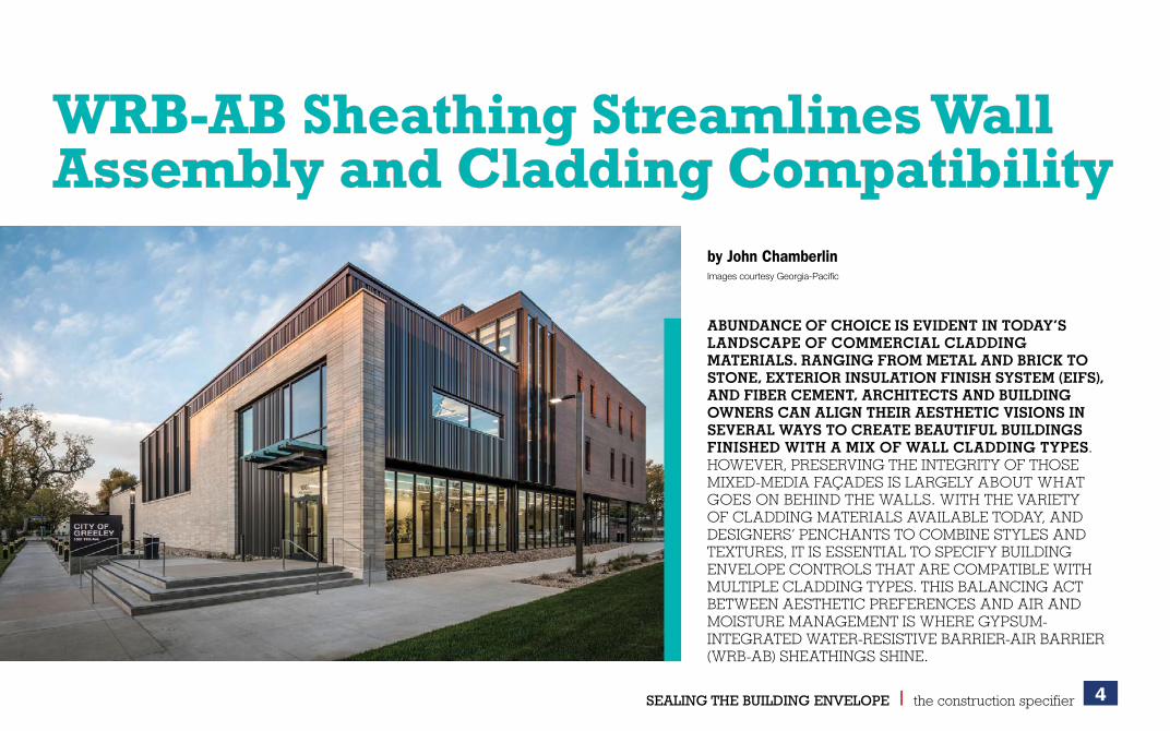
ABUNDANCE OF CHOICE IS EVIDENT IN TODAY’S LANDSCAPE OF COMMERCIAL CLADDING MATERIALS. RANGING FROM METAL AND BRICK TO STONE, EXTERIOR INSULATION FINISH SYSTEM (EIFS), AND FIBER CEMENT, ARCHITECTS AND BUILDING OWNERS CAN ALIGN THEIR AESTHETIC VISIONS IN SEVERAL WAYS TO CREATE BEAUTIFUL BUILDINGS FINISHED WITH A MIX OF WALL CLADDING TYPES. HOWEVER, PRESERVING THE INTEGRITY OF THOSE MIXED-MEDIA FAÇADES IS LARGELY ABOUT WHAT GOES ON BEHIND THE WALLS. WITH THE VARIETY OF CLADDING MATERIALS AVAILABLE TODAY, AND DESIGNERS’ PENCHANTS TO COMBINE STYLES AND TEXTURES, IT IS ESSENTIAL TO SPECIFY BUILDING ENVELOPE CONTROLS THAT ARE COMPATIBLE WITH MULTIPLE CLADDING TYPES. THIS BALANCING ACT BETWEEN AESTHETIC PREFERENCES AND AIR AND MOISTURE MANAGEMENT IS WHERE GYPSUM-INTEGRATED WATER-RESISTIVE BARRIER-AIR BARRIER (WRB-AB) SHEATHINGS SHINE.
WRB-AB Sheathing Streamlines Wall WRB-AB Sheathing Streamlines Wall Assembly and Cladding CompatibilityAssembly and Cladding Compatibility

5SEALING THE BUILDING ENVELOPE l the construction specifier
These integrated materials streamline the entire construction process when different cladding selections are specified. Multi-component wall assemblies with separate WRB and AB layers call for advance work by designers who need to determine proper wall assembly attachments, as well as maintaining a single plane of insulation and weather protection for varying thicknesses of cladding. The separate layers of protection (i.e. WRB and AB) turn into additional levels of complexity for design and construction. Opting for an integrated sheathing system offers simplification and continuity of the air-moisture barrier.
Additionally, integrated gypsum offers more consistency in the WRB thickness and reduces field application issues. Designers need only concern themselves with joints and seams, rough openings, and the penetration treatments.
Challenges of separate componentsIn conventional wall assembly design, separate products may be used for sheathing, WRB, and AB. Thermal control elements like continuous insulation (ci) add another layer of material-selection complexity. Exterior sheathing provides the essential support that is needed to make the barrier layers effective in multi-component cladding systems, and the individual materials must work symbiotically to achieve their overall objectives.1
However, assessing an individual material’s compatibility for thermal, vapor, air, and water/rain control layers can complicate the design. Gypsum-integrated options resolve the complexity more than non-integrated materials, when looking at the half-a-dozen criteria designers must consider, including weather conditions, fastener requirements, and exposure allowances (Figure 1). Further, an incompatible material can threaten the wall assembly’s performance.
Another item to consider is the interface between cladding materials and the WRB. Some claddings, like EIFS, require adhesive and chemical compatibility between their adhesive means of attachment and the WRB. Depending on the configuration, attachment method, and drainage details, the cladding may also influence the location and/or effectiveness of the drainage plane in an exterior wall assembly.
As a system, integrated sheathing starts with either wood or gypsum, modified through proprietary manufacturing processes, to produce sheathings that also act as WRBs and air barrier materials. Once the sheathing is installed, a complete and continuous system is created by sealing the areas of discontinuity with tape or liquid flashing products. An integral WRB gypsum sheathing can act as a drainage plane without concerns for proper sequencing or shingle-lapping, which come with other technologies. However, the interface between the cladding and the WRB should still be reviewed.
Metal panelsMetal panels have become a popular cladding choice for accent or whole-building applications, but heat can build up behind them. As a result, when using liquid-applied or self-adhered WRBs and ABs in conjunction with metal, wall assembly designers need to have an understanding of the in-service temperature limitations of those barriers, which can be as high as 93 C (200 F), depending on the type of building and the kind, design, and location of the metal panel on the
Pros and cons of water-resistive barrier-air barrier (WRB-AB) systems that are available in the market.
Figure 1
6SEALING THE BUILDING ENVELOPE l the construction specifier
structure. Anecdotally, observations made when cladding choice causes a wall assembly to extend beyond the WRB’s temperature limitations indicate delamination, emulsification, or leaching of liquid materials in high-heat situations. Some liquid-applied or self-adhered WRBs and ABs are designed for higher temperatures. However, this sub-category of products underscores the complexity involved in choosing layers for multi-component systems.
StuccoStucco and other commercial building finishes may require metal lath fasteners, so selecting the right sheathing is essential. If magnesium oxide (MgO) boards are used, chemical compatibility with fasteners could become an issue. A five-year study out of Denmark, where MgO boards had been widely used, found salts in the magnesium absorbed ambient humidity, causing fastener corrosion and moisture damage to wood-framing materials.2 While MgO sheathings offer fire-resistance at a lower cost than gypsum, the potential corrosion risk could cause more expensive problems down the roads.
MasonryBrick and cultured stone are popular options for building façades, but they are also highly absorbent. While building cladding is meant to be the first defense against bulk water intrusion, these material selections all but ensure water will penetrate the cladding. In these situations, designers must be confident their selected sheathing and WRB will drain and dry effectively.
When building wraps are selected as the WRB of choice, penetrations and perforations in the material become the issue. As building science expert Joseph Lstiburek explains, moisture intrusion through fastener penetrations is fine, as long as the wall can handle (i.e. thoroughly dry) the amount of moisture that gets through.3 If papers tear because of the wind, insufficient folding around punched openings, or other issues, the amount of moisture infiltrating the wrap could overwhelm the sheathing’s drying capabilities.
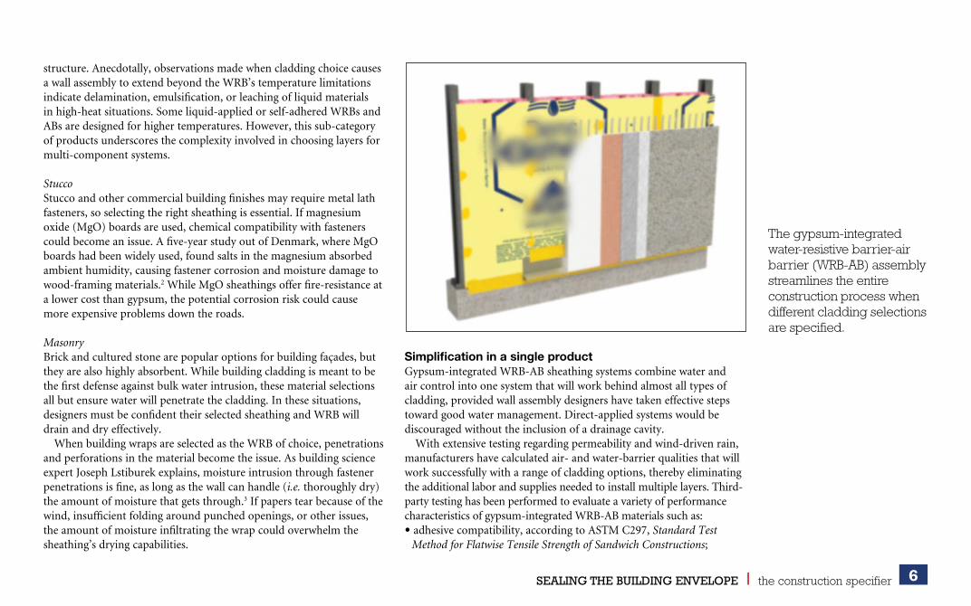
Simplification in a single productGypsum-integrated WRB-AB sheathing systems combine water and air control into one system that will work behind almost all types of cladding, provided wall assembly designers have taken effective steps toward good water management. Direct-applied systems would be discouraged without the inclusion of a drainage cavity.
With extensive testing regarding permeability and wind-driven rain, manufacturers have calculated air- and water-barrier qualities that will work successfully with a range of cladding options, thereby eliminating the additional labor and supplies needed to install multiple layers. Third-party testing has been performed to evaluate a variety of performance characteristics of gypsum-integrated WRB-AB materials such as:• adhesive compatibility, according to ASTM C297, Standard Test
Method for Flatwise Tensile Strength of Sandwich Constructions;
The gypsum-integrated water-resistive barrier-air barrier (WRB-AB) assembly streamlines the entire construction process when different cladding selections are specified.
7SEALING THE BUILDING ENVELOPE l the construction specifier
• drainage capability, per ASTM E2273, Standard Test Method for Determining the Drainage Efficiency of Exterior Insulation and Finish Systems (EIFS) Clad Wall Assemblies, with adhesively attached claddings such as EIFS;
• effectiveness of integrated WRB sheathings when penetrated by mechanical means of cladding attachment, including multiple types of rainscreen bracket and clip systems, in wind-driven rain events, according to ASTM E331, Standard Test Method for Water Penetration of Exterior Windows, Skylights, Doors, and Curtain Walls by Uniform Static Air Pressure Difference; and
• fastener sealability of the WRB, and ability to hold out water under hydrostatic pressure when the barrier is mechanically penetrated, per ASTM D1970, Standard Specification for Self-adhering Polymer Modified Bituminous Sheet Materials Used as Steep Roofing Underlayment for Ice Dam Protection.
In all cases, integrated WRB sheathings have exceeded the code requirements for performance.
Depending on the production process of the integrated materials, the protective WRB-AB layers may be incorporated into the gypsum while the slurry is poured, or applied as a coating to the finished gypsum panels. In both circumstances, the resulting single material eliminates the need for architects or engineers to consider the characteristics of multiple materials and their compatibility with the chosen cladding.
As it is with any building material, proper installation is essential for long-term performance. The gypsum-integrated WRB-AB sheathing panels should be butted tight with a 1.6-mm (1/
16-in.) gap and screwed
to the framing, according to the fastener schedule provided by the manufacturer. Installers will then need to seal the gaps, seams, and fastener locations using liquid-applied flashing, the type and thickness of which would be specified by the sheathing manufacturer. Depending on the situation, a backer rod might be recommended in some instances, but typically, the liquid flashing will suffice.
In terms of code-compliance, the Air Barrier Association of America (ABAA) requires membranes factory-bonded to sheathing to display
inherent self- or fastener sealability, as outlined in paragraph 7.9 of ASTM D1970. Integral gypsum WRB-AB sheathing boards meet this requirement on their own, so installers can be confident they will not have issues with excess moisture infiltrating fastener penetrations.
The step of sealing gaps and fasteners in a visible way with liquid-applied flashing also gives the sheathing an added element of quality control upon installation. Crew-members and building inspectors can easily see missed areas, unlike with building wraps where incorrect folds or laps might be difficult to spot, or liquid-applied moisture barriers that demand a specific thickness for proper performance. Ease of installation for integrated sheathing leaves installers and building owners confident that they are not creating new opportunities for air or water intrusion before the cladding even goes on.
Installers will also be pleased to hear gypsum-integrated sheathings are compatible with a wide range of climate and weather conditions. As climate zones impact the wall assembly as a whole, integrated sheathings can be used in any region, provided other wall components allow for it.
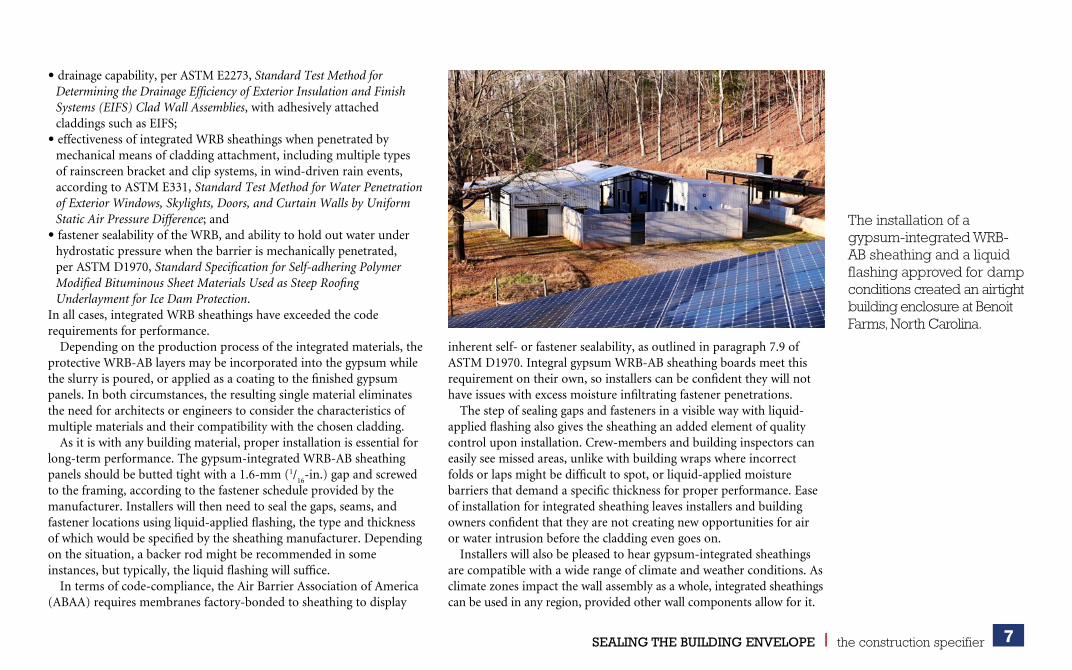
The installation of a gypsum-integrated WRB-AB sheathing and a liquid flashing approved for damp conditions created an airtight building enclosure at Benoit Farms, North Carolina.

8SEALING THE BUILDING ENVELOPE l the construction specifier
Product limitations will vary by type and the manufacturer, but generally the materials can be installed in any weather condition, and can be typically exposed for up to 12 months.
Case studyA North Carolina off-grid property known as Benoit Farms took advantage of gypsum-integrated WRB-AB sheathing to leverage its performance benefits and cladding compatibility. Atlanta-based architecture firm LG Squared was tasked with creating a building that would have reduced energy use while still managing the unpredictable weather of western North Carolina (Climate Zone 4). Dramatic shifts in moisture levels and temperature swings throughout the year, as well as potential forest fires in nearby mountain areas meant the firm needed a sheathing material that could maximize energy efficiency, provide a continuous WRB-AB layer, and protect the building, its occupants, and the surrounding landscape from fire risk.
The integrated sheathing addressed the majority of these concerns with one product and limited trips around the building to install it. The selected wall assembly incorporated a gypsum-integrated WRB-AB sheathing matched with a liquid flashing approved for damp conditions, which sealed the joints, seams, corners, and penetrations. Altogether, this installation created a hydrophobic, monolithic surface to block bulk water, and an airtight building enclosure to achieve energy-efficiency goals, all while allowing for vapor permeability and effective drying and providing fire resistance, as required by the National Fire Protection Association (NFPA) 285, Standard Fire Test Method for Evaluation of Fire Propagation Characteristics of Exterior Wall Assemblies Containing Combustible Components.
With barrier layers fully sealed, the construction team turned its attention to the exterior cladding and aesthetic of the building. The Benoit Farms project called for a layer of ci to achieve its energy-efficiency goals. On top of that, the project called for 20-gauge corrugated steel cladding on the residential building and one barn, and 14-gauge steel on a second barn. The cladding was attached to
20-gauge hat channels and secured through the ci and into 18-gauge metal framing with long roofing screws. Behind the scenes, the gypsum-integrated sheathing provided the air and water barrier, while serving as a rigid substrate for the insulation, and offering structural integrity in the way of shear strength for the wall assembly.
Climate and insulation considerationsTwo schools of thought exist around keeping moisture out of buildings, recognizing cladding as the first line of defense. One approach favors wall assemblies—including cladding selection and installation techniques—designed to keep water out altogether. The other method acknowledges water infiltration in some form and quantity is inevitable, and effective moisture management is more important than keeping water out in the first place.
As discussed, many popular cladding options are susceptible to moisture, making the second approach a logical one for commercial builders. So, assuming some water is bound to get behind the cladding,
Architecture firm LG Squared attached integrated gypsum sheathing to the cladding of the Benoit Farms building to provide a continuous WRB-AB layer and protect the facility and its occupants from potential fires.

9SEALING THE BUILDING ENVELOPE l the construction specifier
gypsum sheathing is a suitable starting point. All gypsum sheathing is vapor permeable and has the capacity to retain its integrity even as it moves through wetting and drying cycles. In selecting a gypsum-integrated WRB-AB sheathing, designers benefit from this quality, as well as the consistency of a known permeability level that will not be changed by the addition of separate control layers. For example, an integrated sheathing rated at 25 perms will retain that rating on installation because it already accounts for the permeability of the WRB-AB. This is in contrast to a non-integrated sheathing whose permeability changes depending on the control layers applied.
However, the issue is complicated by the widespread use of continuous insulation code requirements on commercial buildings. Depending on the type of insulation and its installation—directly up against the WRB-AB layer, or within the cladding installation framing—the location of the drainage plane and drying capabilities of the wall assembly may change.
For example, in a cold climate, designers may choose an integrated WRB-AB sheathing, followed by mineral wool ci, and an air gap between the insulation and their cladding of choice. This wall assembly should dry well to the outside with the cladding spaced off insulation. However, if a foil-faced polyisocyanurate (ISO) ci is used, it would not dry well to the outside. Pressed up against the WRB-AB layer, the ISO would stop movement of moisture at its surface, and designers have to provide a drainage cavity.
With the thermal control and moisture management requirements of wall assemblies varying by region, designers should remove as many complications as possible from the specification process. Gypsum-integrated WRB-AB sheathings achieve this uniform approach to moisture management, letting designers focus on the remaining building science requirements, regardless of the cladding.
Fire compliance achievedThe benefits of gypsum-integrated WRB-AB sheathing do not just stop at air and moisture protection and cladding compatibility. These materials also help buildings meet fire-safety standards.
WRBs, ABs, and ci are all intended to improve the building performance. However, a renewed focus on exterior wall assemblies considers the propagation of fire due to the design and cladding materials. This issue was underscored by the 2017 Grenfell fire in London, United Kingdom. Specifically, authorities are enforcing code requirements of wall assemblies and compliance with NFPA 285 testing.
To meet the International Building Code (IBC) requirements for wall assembly fire performance, all WRBs must be in compliance with NFPA 285. Unlike systems comprising a primary WRB material and flashing accessories that are sometimes combustible, gypsum-integrated WRB-AB assemblies start with the fire-resistance of gypsum and typically incorporate noncombustible WRB sheathing with liquid flashing accessories. It is important designers who are creating wall assemblies with wood-based integrated sheathings, or integrated sheathings with a pre-cured liquid membrane on the surface, should recognize these are combustible materials and must find other ways to address fire-resistance requirements.
Integrated gypsum sheathing has been installed on Eagle's Landing Apartments in Burlington, Virginia.
10SEALING THE BUILDING ENVELOPE l the construction specifier
AuthorsJohn Chamberlin is a senior product
manager at Georgia-Pacific. He is
responsible for the DensElement
Barrier System and the DensDefy line
of products. Chamberlin has worked
in the building materials industry
for his entire career, focusing on new product
development for disruptive technologies in the
building envelope space. Chamberlin is on the board
of the Air Barrier Association of America (ABAA).
He graduated from the University of Tennessee with
a bachelor’s degree in marketing and later received
his MBA from Emory University. He can be reached
via e-mail at [email protected].
Key TakeawaysWith the variety of cladding materials available today,
and designers’ penchants to combine styles and
textures, it is essential to specify building envelope controls that are compatible with multiple cladding types. This balancing act between the aesthetic preferences and air and moisture management is where gypsum-integrated water-resistive barrier-air barrier (WRB-AB) sheathings shine.
MasterFormat No.06 16 43–Gypsum Sheathing
UniFormat No.B2010.20–Exterior Wall Construction
Key WordsDivision 06Air barrierCladdingGypsum sheathingWater-resistive barrierWaterproofing
ADDITIONAL INFORMATION
Some designers may wonder if all combinations of WRB/AB products and sheathing should be tested together to meet NFPA 285. Generally, if the exterior wall assembly includes a combustible component, then a test or engineering judgment is necessary. If all components of the specified assembly are noncombustible, then testing is unnecessary.
As of 2018, IBC updated its standard method for evaluating fire propagation characteristics for external wall assemblies. It specifies that NFPA 285 compliance testing criteria no longer considers WRB flashings or accessories to be part of the barrier, as they comprise such a small portion of the assembly. More to the point, this update separates multi-component assemblies into the primary WRB and accessories or flashing products. For example, a termination mastic on a self-adhered membrane system would be consider an accessory, while the membrane itself would be considered the primary WRB. With this in mind, sheathing that is made from fiberglass mat with a gypsum core—classified as a noncombustible WRB—is exempt from NFPA 285 assembly testing, and IBC 1402.5 requirements for combustible WRBs are inapplicable.
With that in mind, using an NFPA 285-approved WRB-AB sheathing simplifies the cladding process by bypassing the need for any additional testing specific to the barrier.
Give the design every advantageAs integrated WRB-AB sheathings increase in popularity, now is the time for architects and designers to give these materials a closer look. Why restrict cladding possibilities based on the parameters of inflexible multi-component barrier layer options? As an industry innovation, integral WRB-AB sheathing systems support cladding versatility and maintain fire and water-resistance compliance while simplifying wall assembly design and supporting efficient construction.
Broadening a world of design possibilities without the complication of individual component synergy eliminates the hassle of accounting for the differences across a variety of cladding and sheathing combinations.
With gypsum-integrated WRB-AB sheathing, designers can accent the north-facing side of a building with brick, while styling the south wall in EIFS. cs
Notes1 Consult “Considerations in the Design of Cladding Systems with Continuous Exterior Insulation” by Mar J. Klos.2 Details at www.sciencedirect.com/science/article/pii/S1876610217349378.3 Visit www.buildingscience.com/documents/insights/bsi-067-stuck-on-you.
11SEALING THE BUILDING ENVELOPE l the construction specifier
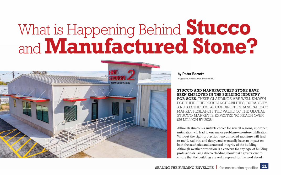
by Peter BarrettImages courtesy Dörken Systems Inc.
STUCCO AND MANUFACTURED STONE HAVE BEEN EMPLOYED IN THE BUILDING INDUSTRY FOR AGES. THESE CLADDINGS ARE WELL KNOWN FOR THEIR FIRE-RESISTANCE ABILITIES, DURABILITY, AND AESTHETICS. ACCORDING TO TRANSPARENCY MARKET RESEARCH, THE VALUE OF THE GLOBAL STUCCO MARKET IS EXPECTED TO REACH OVER $16 MILLION BY 2026.1
Although stucco is a suitable choice for several reasons, improper installation will lead to one major problem—moisture infiltration. Without the right protection, uncontrolled moisture will lead to mold, wall rot, and decay, and eventually have an impact on both the aesthetics and structural integrity of the building. Although weather protection is a concern for any type of building, professionals using stucco cladding should take greater care to ensure that the buildings are well prepared for the road ahead.
What is Happening Behind Stucco and Manufactured Stone?

12SEALING THE BUILDING ENVELOPE l the construction specifier
Once viewed as a cladding system with the ability to solve moisture problems, stucco is now seen as causing hidden wall rot. One of the places this had first become widely known was in Vancouver, British Columbia, Canada, in the 1990s, when stucco bonded to plastic weather-resistive barriers (WRBs) had rotted oriented strand board (OSB) behind the WRBs.2 Then the issue moved south and east to places like Minneapolis, Minnesota, and Greensborough, South Carolina. First, it was noticed on multistory, wood-frame buildings because rain exposure increases with height, and then on regular wood-frame low-rises.
In 2018, building expert Joe Lstiburek said construction professionals did not learn from Vancouver, and he predicts an impending ‘stucco-pocalypse.’3
The industry needs to come together to make buildings better by specifying the right system made up of the suitable products and follow up to ensure proper installation.
Signs of failureTrapped moisture can cause severe issues that may not be evident until it is too late. For example, the commonly known ‘stucco tear’ stains that appear under installations such as windows are signs of moisture-induced damage to the wall systems. Other warning signs include:• dark spots; • heavy staining;• odor;• cracks;• bulges in the stucco finishes; and • missing stucco.Without preventative measures, these issues are likely to have a negative impact on the overall structural integrity and safety of the building.
The problem begins during installationIn the author’s experience, there is not as much energy going across assemblies as there used to be. This is due to increased thermal
resistance (i.e. more insulation in the walls). Reduced energy flow limits the drying abilities of wall assemblies when wet. The more efficient the assembly, the lower the drying potential. So, as the drying potential is reduced, so must a wall’s wetting potential.
Stucco is also considered a reservoir cladding, which means it can absorb and store rainwater. Claddings like this can be thought of as ‘moisture capacitors.’ In effect, wetting charges them. It is part of a group of materials such as brick, unpainted wood, and fiber cement that will store water. Claddings like vinyl, aluminum siding, or metal panels would not be considered reservoir claddings.4
Further, gypsum sheathing is vapor permeable and OSB sheathing is vapor impermeable.
How is high vapor permeability a problem? When a reservoir cladding discharges inwardly, the inwardly driven vapor can easily pass through the exterior gypsum sheathing and damage the wall cavity and interior finishes.
Located in front of a spun-bonded polypropylene, self-adhering air- and water-resistive barrier, the rainscreen system featured a drainage and ventilation layer in one, but also incorporates the lath for the first scratch coat of the stucco.

13SEALING THE BUILDING ENVELOPE l the construction specifier
How is lower vapor permeability a problem? The wall assembly itself cannot dry outward, but, there is an additional issue with OSB. Unlike plywood, when OSB is wetted from the exterior, it is incapable of redistributing moisture within itself. OSB is significantly lower in permeance than plywood. Plywood can pull water into its structure and wick it away from the point of wetting and subsequently release it both inward and outward as it increases in permeance. OSB has none of those properties. With OSB, the moisture redistribution must happen on its surface. Hence, the absolute need for an airspace over its exterior surface.
On top of this, Lstiburek explains the physical characteristics of stucco used in applications have also changed. Over the years, the components have gone from lime-based, lime-Portland cement-based, Portland cement-based, and polymer modified. With each step it has gotten stronger, but also created a less vapor permeable mixture. Today’s stuccos do not breathe as well as the old kinds. These changes have led to very significant problems with stucco, particularly in places where it rains a great deal.
Building professionals understand it is critical to keep water and dampness from getting into a structure by preventing moisture from moving through the wall from the outside. This is accompanied by putting the right measures in place to keep any moisture from penetrating the system.
The initial solution was to use two layers of WRB—the outer layer would act as a bond break and the inner one would be the ‘true’ dimensionally stable WRB. However, these assemblies had lacked enhanced drainage and drying.
Professionals have since learned the more effective means of accomplishing both is to provide a drainage mat between the bond break and the WRB. Moisture can be fully blocked by uncoupling the stucco from the rest of the wall and installing the stucco over a vented and drained air gap.
Best practices when installing commercial stucco wall assembliesIn a steel stud wall with gypsum sheathing it is very important to install some type of water and air control layer on the exterior of the gypsum sheathing. This layer also needs to be vapor open to allow the wall to dry outward. This layer could be a fluid-applied, fully adhered, vapor-permeable membrane. On it could be sheet product such as a WRB film. Another option would be gypsum sheathing with an integral water control layer with joint treatment. Over this layer goes a drainage mat that resists hydrostatic pressure and prevents inward vapor drive, such as a dimple mat with a mortar screen that allows for air gaps on
Illustration of stucco installed over a rainscreen with pre-installed fiberglass lath.
Moisture damage on wood-frame, low-rise building.Photo courtesy Building Science Corporation

14SEALING THE BUILDING ENVELOPE l the construction specifier
both the interior and exterior side of the membrane. The stucco layer goes over the mat.
Nothing changes for a steel stud wall with OSB sheathing except when the OSB sheathing may have a fluid-applied or an integral water control layer.
With a drained and ventilated stucco cladding, the wall assembly can dry to the outside into the air gap behind the stucco. With a vapor-closed drainage mat, inward vapor drives through the stucco are completely blocked.
The same approach works behind natural stone claddings and manufactured stone veneers.
Providing a gap between the stucco and the substrates creates an airspace between the cladding and the rest of the wall. This gap provides two important functions—one is to allow outward drying through a vapor-open, water- and air-control layer, and the second is to prevent inward wetting as a result of moisture coming through a reservoir cladding. With the right kind of space, stucco will last hundreds of years.
When it comes to creating the gap, various methods and materials can be used to separate the cladding from the substrates. One of these moisture protection approaches, and arguably perhaps the most effective, is using a dimpled membrane, or ventilated rainscreen. By disconnecting the cladding system, it uncouples it from the rest of the assembly, thereby improving longevity and durability. Without breaking the bond between commonly used housewraps and stucco to provide an air gap, coupled with the use of an alkali cementitious base scratch coat that can help act as a surfactant, stucco cladding systems will continue to fail.
Bringing the concept to lifeA fire station is an icon of safety, part of the entire community, and central to everyday life. Recognizing the need to create a building that symbolized these values through design and performance was the driver behind the newly designed and rebuilt Lockhart Fire Rescue
Ventilated rainscreen membrane that is made of a special high-density polyethylene (HDPE) with pre-installed glass lath.
The exterior of the fire station is made up of stucco cladding. This design required a durable building envelope that could withstand the notoriously hot and humid climate in Texas with a focus on airtightness and vapor permeability.
15SEALING THE BUILDING ENVELOPE l the construction specifier
Headquarters in Lockhart, Texas. Designed by architect Robert Steinbomer and built by Countywide Builders, the new facility totals 251 m2 (2700 sf).
The exterior of the fire station is made up of stucco cladding, a design element that can be resistant to fire, rot, mold, impact, and termite infestation for as long as 100 years when properly installed. The design required a durable building envelope that could withstand a notoriously hot and humid climate in Texas with a focus on airtightness and vapor permeability.
To create a high-performance wall system, a two-in-one rainscreen and lath was selected. Located in front of a spun-bonded polypropylene, self-adhering air- and water-resistive barrier, the rainscreen system features a drainage and ventilation layer in one, but also incorporates lath for the first scratch coat of the stucco. Simplifying many steps, the ventilated rainscreen with pre-installed glass lath will help to eliminate the building enclosure’s risk of solar-driven moisture. At the same time, this one-step moisture control and lath system would allow any incidental moisture from within the wall to dry to the outside.
Unlike traditional methods, the fire station’s exterior cladding is efficiently uncoupled from the rest of the assembly, thereby giving it longevity and durability.
ConclusionWhen stucco and manufactured stone buildings are built correctly, they can provide many benefits, which include energy efficiency, sustainability, durability, and also increased fire protection. However, when moisture protection is unaddressed, the effects can be detrimental. Getting ahead of water and dampness is the only way to ensure that new stucco and manufactured stone buildings give their full potential.
There are products incorporating all these qualities. For example, ventilated rainscreen membranes made of a special high-density polyethylene (HDPE) with pre-installed glass lath are multifunctional and provide high levels of moisture permeability along with the all-important water- and air-tightness. cs
AuthorPeter Barrett is the product and marketing manager for Dörken Systems. He has been with the company for more than 12 years. However, his involvement with the design community and building
materials industry spans over 25 years. Barrett holds a BA (Hons.) from Queen’s University, Kingston, Ontario, and an MBA from Wilfrid Laurier University, Waterloo, Ontario. Barrett is a member of the board of directors for the Air Barrier Association of America (ABAA). He can be reached at [email protected].
Key TakeawaysStucco and manufactured stone have been used in the building industry for ages. These claddings are well-known and well-used for their leading properties of fire resistance, durability, and aesthetics. Although it is evident stucco is a strong choice for several reasons, improper installation will lead to one major problem—moisture intrusion.
Without the right protection, uncontrolled moisture will lead to mold, wall rot, and decay, and eventually have an impact on both the aesthetics and structural integrity of the building. Although weather protection is a concern for any type of building, professionals using stucco cladding should take greater care to ensure the buildings are well prepared for the road ahead.
MasterFormat No.04 00 00–Masonry 09 20 00–Plaster and gypsum board09 24 23-Cement Stucco
UniFormat No. B2010.80–Exterior Wall Supplementary Components
Key WordsDivisions 04,09Air barrierCladdingManufactured stone
ADDITIONAL INFORMATION
Moisture controlRainscreen systemsStuccoWeather-resistive barriers
Notes1 Consult www.transparencymarketresearch.com/stucco-market.html.2 Read Joe Lstiburek’s article “BSI-102: The Coming Stucco-Pocalypse” at buildingscience.com/documents/building-science-insights/bsi-102-coming-stucco-pocalypse.3 See Note 3.4 Visit www.buildingscience.com/documents/building-science-insights/bsi-061-inward-drive-outward-drying.
16SEALING THE BUILDING ENVELOPE l the construction specifier
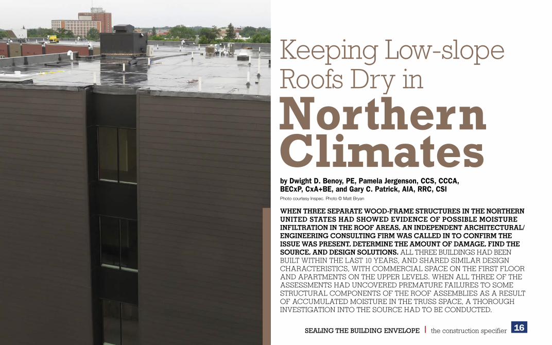
by Dwight D. Benoy, PE, Pamela Jergenson, CCS, CCCA, BECxP, CxA+BE, and Gary C. Patrick, AIA, RRC, CSIPhoto courtesy Inspec. Photo © Matt Bryan
Keeping Low-slope Keeping Low-slope Roofs Dry in Roofs Dry in
WHEN THREE SEPARATE WOOD-FRAME STRUCTURES IN THE NORTHERN UNITED STATES HAD SHOWED EVIDENCE OF POSSIBLE MOISTURE INFILTRATION IN THE ROOF AREAS, AN INDEPENDENT ARCHITECTURAL/ENGINEERING CONSULTING FIRM WAS CALLED IN TO CONFIRM THE ISSUE WAS PRESENT, DETERMINE THE AMOUNT OF DAMAGE, FIND THE SOURCE, AND DESIGN SOLUTIONS. ALL THREE BUILDINGS HAD BEEN BUILT WITHIN THE LAST 10 YEARS, AND SHARED SIMILAR DESIGN CHARACTERISTICS, WITH COMMERCIAL SPACE ON THE FIRST FLOOR AND APARTMENTS ON THE UPPER LEVELS. WHEN ALL THREE OF THE ASSESSMENTS HAD UNCOVERED PREMATURE FAILURES TO SOME STRUCTURAL COMPONENTS OF THE ROOF ASSEMBLIES AS A RESULT OF ACCUMULATED MOISTURE IN THE TRUSS SPACE, A THOROUGH INVESTIGATION INTO THE SOURCE HAD TO BE CONDUCTED.
Northern Northern ClimatesClimates

17SEALING THE BUILDING ENVELOPE l the construction specifier
BackgroundAll three buildings had similar non-ventilated, low-slope roof assemblies utilizing wood trusses with a polyethylene vapor retarder on the bottom of the trusses covered with a gypsum ceiling. Blown-in fiberglass or cellulose insulation filled the truss space from the ceiling to the bottom of the roof deck on all three buildings. Oriented strand board (OSB) of 13-mm (1/
2-in.) thickness was installed over the trusses as the roof deck. Rigid board
insulation was installed over the OSB, followed by the roof membrane, which was a gravel-surfaced built-up roof in one case, a ballasted ethylene propylene diene terpolymer (EPDM) single-ply membrane on another, and a mechanically fastened thermoplastic polyolefin (TPO) single-ply membrane on the third.
Water intrusion was not evident in any of the buildings. A survey of the roof surfaces showed they were in good condition. Occupants in two of the buildings reported mold issues, which led to further investigation. Maintenance people walked on the roof of the third building and discovered soft spots, which turned out to be locations where the OSB roof deck had lost its structural integrity due to moisture degradation.
It was apparent moisture-laden air had migrated into the truss space of all three buildings and condensed in the upper reaches of the roof assemblies. This resulted in excessive moisture buildup, mold, and rot of the OSB structural roof deck and structural trusses in a substantial portion of the roof area.
Ideally, the vapor retarder should act to minimize the amount of moisture vapor from the interior of the buildings getting into this space. In the northern climate where these projects were located, the vapor drive in the winter is mainly from the warm interior to the cold exterior. The warm interior air carries moisture vapor that will condense on surfaces below the dewpoint, the temperature at which condensation can occur.
The investigations found many bypasses in the vapor retarder that would allow the warm, moist interior air to migrate into the truss space. The party walls between apartment units, which were a double-stud wall construction, interrupted the continuity of the vapor retarder.
Similarly, all interior partition walls resulted in a discontinuity in the vapor retarder at the ceiling. This was exacerbated by the penetrations through the top plate of the wall by plumbing stacks and wiring. Penetrations through the ceiling, such as sprinkler heads and electrical boxes for light fixtures, were also found unsealed to the vapor retarder.
Two of the buildings had ducts from bathroom and dryer vents running through the truss space. Some of these ducts were not well-sealed at the joints, thereby introducing moist air directly into a space with a potential for condensation.
Figure 1
The first repair option for the roof of the Coborn Plaza Apartments in Minnesota. Images courtesy Inspec
Figure 2
The second repair option.
18SEALING THE BUILDING ENVELOPE l the construction specifier
In the authors’ opinion, the roof assembly would perform satisfactorily if the ceiling vapor retarder were perfectly constructed. However, in this type of construction, it was impossible to perfectly construct a vapor retarder at the ceiling level because of the discontinuities. Ventilation of the truss space is an ineffective option to manage moisture. Unlike a steep-slope attic space, there is very little, if any, room to create airflow over relatively long distances.
Perhaps, the motivation to design an assembly as such would be to minimize the insulation costs related to the energy code requirements of recent years. While the amount of insulation installed exceeds the code requirement, the material and labor to install it were less than a code-compliant insulation installed above the roof deck. Filling the truss space with noncombustible insulation also eliminated the need for firestopping and draftstopping as noted in the 2000 edition of the International Building Code (IBC), in force at the time these buildings were constructed.
Installing the vapor retarder at the roof deck level affords a better opportunity to achieve a complete vapor retarder. This would be an easy way to provide continuity across party walls and to seal penetrations. The vapor retarder must also be continuous from the roof to the exterior walls. This might be accomplished by using spray foam insulation within the truss space at the exterior walls.
On one building, the Coborn Plaza Apartments in central Minnesota, the problem was discovered approximately five years after the building was constructed when tenants of the top-floor observed mold on the gypsum ceiling and complained of musty odors. A mold remediation project was undertaken and included removal of the gypsum ceiling, vapor/air barrier, and blown-in insulation. It was discovered the exhaust ducts for the
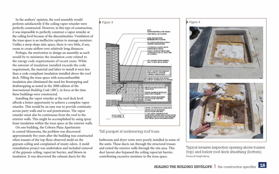
Figure 3
Tall parapet at nonbearing roof truss.
Figure 4
Typical invasive inspection opening above trusses (top) and below roof deck sheathing (bottom).Photos © Dwight Benoy
bathroom and dryer vents were poorly installed in some of the units. These ducts ran through the structural trusses and exited the exterior walls through the rim area. This duct layout also bypassed the ceiling vapor/air barrier, contributing excessive moisture to the truss space.

19SEALING THE BUILDING ENVELOPE l the construction specifier
The remediation work included the cleaning and sealing of the ducts, which was thought to be the only cause of the problem at that time. The moldy framing and structural roof deck were cleaned and painted with an anti-microbial paint. Some of the rotted deck was reinforced from below with additional OSB sheathing and framing.
Inspection openings from the interior were then made to verify if the remediation was effective. Excessive moisture presence was discovered. It is important to know the moisture buildup had occurred in a matter of months following the remediation. Investigation began for another source of moisture. Hygrothermal modeling was conducted to confirm or deny the inadequacy of the vapor/air barrier. Results indicated a propensity for moisture to accumulate.
Designing the repairsDue to the damages already experienced and the potential for more to develop, it was determined Coborn Plaza needed a full roof replacement. The primary challenge was to develop a complete vapor/air barrier below the dewpoint temperature that also tied into the wall’s vapor/air barrier in order to envelope the building.
Repair options were developed and hygrothermal modeling was conducted for all the ideas. The owner required all work to be conducted from above the ceiling to minimize disruption to the tenants.
First optionThis option was intended to create a complete vapor/air barrier by installing spray foam over the polyethylene sheeting and bottom chord of the truss (Figure 1, page 17). This required the removal of the existing system down to the structural roof deck and also a significant portion of the deck to facilitate the vacuuming of the existing blown-in insulation out of the truss space and the installation of spray foam and new blown-in insulation. New tapered insulation and roof membrane above the structural roof deck were part of this solution.
Second optionThe second option required removal of the existing system down to the structural roof deck and the replacement of any wet, rotted, and/or moldy deck and blown-in insulation (Figure 2, page 17). A roof vapor/air barrier would be applied on the structural roof deck.
Figure 5
Approximate areas of roof deck and insulation replacement.Image courtesy Inspec
Figure 6
Typical work at roof perimeter.Image courtesy Inspec. Photo © Dwight Benoy
20SEALING THE BUILDING ENVELOPE l the construction specifier
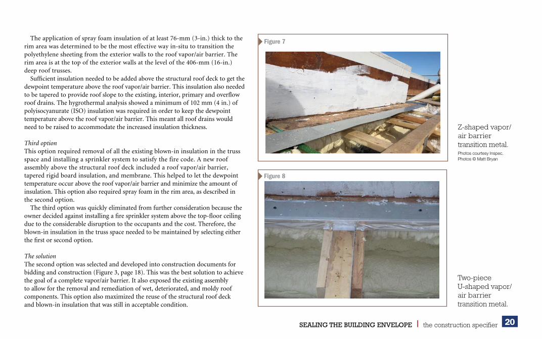
The application of spray foam insulation of at least 76-mm (3-in.) thick to the rim area was determined to be the most effective way in-situ to transition the polyethylene sheeting from the exterior walls to the roof vapor/air barrier. The rim area is at the top of the exterior walls at the level of the 406-mm (16-in.) deep roof trusses.
Sufficient insulation needed to be added above the structural roof deck to get the dewpoint temperature above the roof vapor/air barrier. This insulation also needed to be tapered to provide roof slope to the existing, interior, primary and overflow roof drains. The hygrothermal analysis showed a minimum of 102 mm (4 in.) of polyisocyanurate (ISO) insulation was required in order to keep the dewpoint temperature above the roof vapor/air barrier. This meant all roof drains would need to be raised to accommodate the increased insulation thickness.
Third optionThis option required removal of all the existing blown-in insulation in the truss space and installing a sprinkler system to satisfy the fire code. A new roof assembly above the structural roof deck included a roof vapor/air barrier, tapered rigid board insulation, and membrane. This helped to let the dewpoint temperature occur above the roof vapor/air barrier and minimize the amount of insulation. This option also required spray foam in the rim area, as described in the second option.
The third option was quickly eliminated from further consideration because the owner decided against installing a fire sprinkler system above the top-floor ceiling due to the considerable disruption to the occupants and the cost. Therefore, the blown-in insulation in the truss space needed to be maintained by selecting either the first or second option.
The solutionThe second option was selected and developed into construction documents for bidding and construction (Figure 3, page 18). This was the best solution to achieve the goal of a complete vapor/air barrier. It also exposed the existing assembly to allow for the removal and remediation of wet, deteriorated, and moldy roof components. This option also maximized the reuse of the structural roof deck and blown-in insulation that was still in acceptable condition.
Figure 7
Z-shaped vapor/air barrier transition metal.Photos courtesy Inspec. Photos © Matt Bryan
Figure 8
Two-piece U-shaped vapor/air barrier transition metal.

21SEALING THE BUILDING ENVELOPE l the construction specifier
Vapor/air barrier continuityVapor/air barrier continuity from the wall to the roof is the key consideration and the toughest challenge for the repair design. Installing the roof vapor/air barrier on top of the structural roof deck required transitioning the barrier through the deck to the rim area to complete the envelope. This was solved by designing a U-shaped sheet metal to wrap around the structural roof deck edge. This provides a surface on the bottom to receive the spray foam insulation applied to the rim area, and also a layer on top to which the self-adhering vapor/air barrier could be bonded.
Other considerationsBesides selecting the second option, other design considerations included:• the rim area had to be accessed from above, requiring
the removal of some of the structural roof deck and blown-in insulation along the roof edge parapet;
• parapet varies in height, with some of the low parapet design being challenged by the additional insulation thickness;
• trusses run parallel and perpendicular to the parapet, which causes variations in the rim area conditions;
Figure 9
Roof vapor/air barrier at roof perimeter.
• structural roof deck removal along the parapets compromised the structural integrity of the roof perimeter at some conditions, so an engineered solution, including continuous steel angles and the addition of plywood sheathing to reinforce the structure, was required;
• an allowance was included in the base bid for deck and blown-in insulation replacement (the allowance amount was an educated estimate of how much replacement would be required based on the previous investigation work, and unit prices were requested to be used to charge against this allowance); and
Plywood and sheet metal angle parapet reinforcement. Vapor/air barrier applied to field of roof.

22SEALING THE BUILDING ENVELOPE l the construction specifier
• during the design process, input was provided by a local roofing contractor (collaboration amongst the contractor, owner, and the architect/engineer [A/E] helped develop a constructible design that achieved the goals and minimized costs and delays).
Construction challengesThree contractors were invited to bid the project, and they provided input during the bidding process. One key, high-risk factor in constructing the second option was that doing all the work from the top side would leave the roof open and at the mercy of the weather for a substantial portion of time each day. Some days had greater exposure than others, depending on the amount of deck and blown-in insulation being replaced.
During the design phase, based on investigation-generated test results and observations, it was decided to make 60 invasive inspection openings prior to the start of construction to provide an idea of where the deck and insulation would need to be replaced (Figure 4, page 18). This would help the contractor better plan the construction work. The contractor awarded the reroofing project would make and repair the inspection openings.
Since litigation had been initiated, parties involved with the original construction had an interest in observing the existing construction. To minimize the disruption to the contractor’s operations, all interested parties were allowed to observe and conduct moisture testing at each of the 60 invasive inspection openings. The owner hired an environmental consulting firm in order to conduct moisture tests and sampling for fungal analysis on its behalf. This consultant had provided a report including a roof plan showing the test results.
Moisture contentBased on the 60 invasive inspection openings, test results, and observations, a roof plan was developed showing the approximate areas where roof deck sheathing and blown-in insulation would most likely require replacement (Figure 5, page 19). The final determination of what needed replacement would be made by the contractor when each area was opened daily. While onsite performing their periodic observations,
Figure 10
Figure 11
Blown-in insulation.Photos courtesy Inspec. Photos © Dwight Benoy
Mold remediation paint.
23SEALING THE BUILDING ENVELOPE l the construction specifier
the A/E assisted the contractor to determine what needed to be replaced. A hand-held moisture meter was utilized daily in order to determine the moisture content of the OSB structural roof deck. Industry convention indicates 16 percent moisture content would be the threshold for requiring replacement.
The moisture meter did not provide useful readings for determining the need to replace the blown-in fiberglass insulation. Samples of insulation were taken to determine oven-dried moisture content by weight in order to develop a correlation with the moisture meter readings. A correlation could not be determined, so the decision to replace insulation was somewhat subjective. Wherever mold was detected on the OSB deck, the underlying insulation was replaced since mold spores can migrate into the insulation. The contractor also determined whether excess moisture was present by sight and touch.
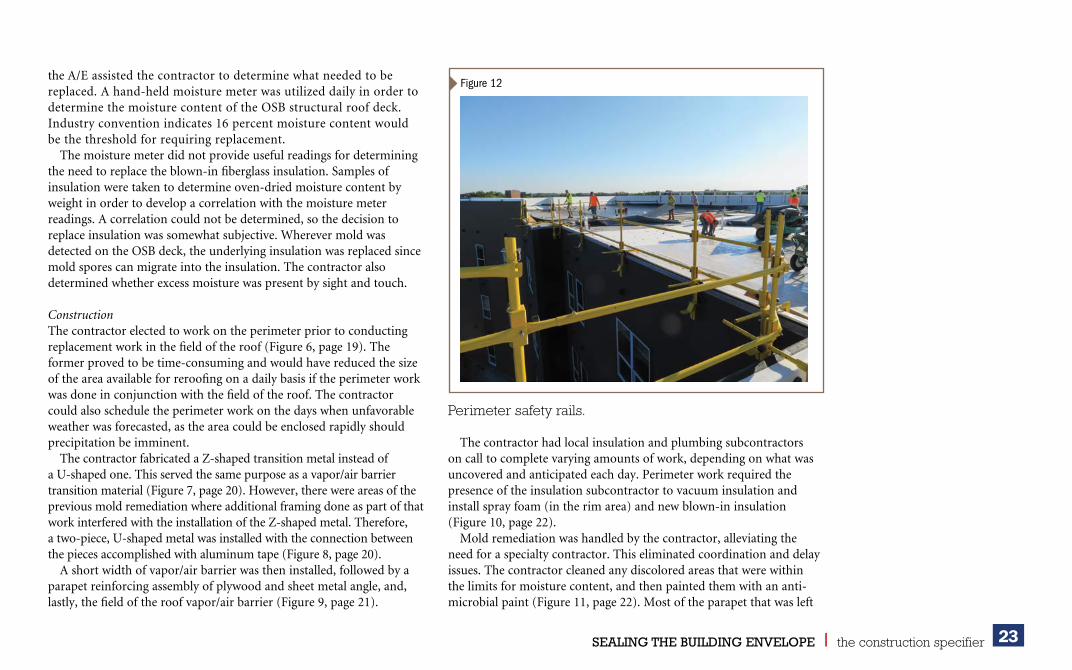
ConstructionThe contractor elected to work on the perimeter prior to conducting replacement work in the field of the roof (Figure 6, page 19). The former proved to be time-consuming and would have reduced the size of the area available for reroofing on a daily basis if the perimeter work was done in conjunction with the field of the roof. The contractor could also schedule the perimeter work on the days when unfavorable weather was forecasted, as the area could be enclosed rapidly should precipitation be imminent.
The contractor fabricated a Z-shaped transition metal instead of a U-shaped one. This served the same purpose as a vapor/air barrier transition material (Figure 7, page 20). However, there were areas of the previous mold remediation where additional framing done as part of that work interfered with the installation of the Z-shaped metal. Therefore, a two-piece, U-shaped metal was installed with the connection between the pieces accomplished with aluminum tape (Figure 8, page 20).
A short width of vapor/air barrier was then installed, followed by a parapet reinforcing assembly of plywood and sheet metal angle, and, lastly, the field of the roof vapor/air barrier (Figure 9, page 21).
The contractor had local insulation and plumbing subcontractors on call to complete varying amounts of work, depending on what was uncovered and anticipated each day. Perimeter work required the presence of the insulation subcontractor to vacuum insulation and install spray foam (in the rim area) and new blown-in insulation (Figure 10, page 22).
Mold remediation was handled by the contractor, alleviating the need for a specialty contractor. This eliminated coordination and delay issues. The contractor cleaned any discolored areas that were within the limits for moisture content, and then painted them with an anti-microbial paint (Figure 11, page 22). Most of the parapet that was left
Figure 12
Perimeter safety rails.

24SEALING THE BUILDING ENVELOPE l the construction specifier
AuthorsDwight D. Benoy, PE, was employed at Inspec, a building envelope consulting and engineering/architectural firm. He focuses his practice in forensic engineering of the building envelope. Benoy can be reached via e-mail at [email protected] C. Patrick, AIA, RRC, CSI, is an executive vice-president of Inspec, and has been with the company since 1977. He oversees the roofing services area of Inspec, which includes evaluations, design, peer reviews, construction
observation and testing, and forensics. Patrick can be reached via e-mail at [email protected].
Pamela Jergenson, CCS, CCCA, BECxP, CxA+BE, is a senior consultant for exterior walls with Inspec, a building envelope consulting engineering/architectural firm. She is an expert in hygrothermal analysis. She can be
reached at [email protected].
Key TakeawaysThe current design of some wood-framed, non-ventilated roof assemblies in northern climates results
ADDITIONAL INFORMATION
in place was remediated when the perimeter work was being constructed, which proved to be the most efficient.
The estimated amount of existing roof deck sheeting removal, based on the 60 invasive inspections openings, was 743 m2 (8000 sf). The actual amount of existing roof deck sheeting removal was 557 m2 (6000 sf).
While conducting the invasive inspection openings, and subsequently during the reroofing work, it was observed the TPO roof membrane plates were severely corroded in much of the roof area. This reduced the wind-uplift resistance of the roof membrane. The contractor was conscious of the need to respond quickly should a high wind event occur. Fortunately, the reroofing work was completed without incident.
The contractor removed tear-off debris from the site daily. The debris was lowered by crane into dump trucks. New materials were hoisted daily with only a one- to two-day stockpile on the roof. The crane and roofing materials were staged on the streets running adjacent to the building, but only at certain locations, thereby resulted in long travel distances across the existing roof in some areas. The City of St. Cloud, Minnesota, allowed the streets to be temporarily closed. Access to the retail establishments and egress from nearby buildings was continuously maintained, but was an ongoing public safety challenge.
Perimeter safety was accomplished by attaching rails to the parapet (Figure 12, page 23). A safety monitor was also assigned to work with the crew that was applying the low-rise foam adhesive for the insulation attachment.
The fully adhered EPDM membrane over the tapered insulation system provided a fully draining roof with a finished appearance. Even with all of the construction challenges, the roof was completed in a timely manner.
ConclusionThe owner, contractor, and A/E worked together to achieve the goal of taking a sick building and making it well. All parties understood from the start shortcuts could not be taken. As with most projects, some surprises were encountered, but these were quickly resolved
in discontinuities in the vapor/air barriers, which allows moisture-laden air to migrate into the truss space and condense. This is resulting in excessive moisture and leading to extensive problems early in the roof’s service life, including mold, rot, and structural issues. Designs permitting a continuous vapor/air barrier from the wall to the roof should be utilized in roof assemblies of this sort in northern climates to avoid dangerous and costly failures.
MasterFormat No.06 11 00–Wood Framing07 53 00–Elastomeric Membrane Roofing07 21 00–Thermal Insulation
UniFormat No.B3010.50–Low-slope Roofing
Key WordsDivisions 06, 07Gypsum ceilingInsulationLow-slope roofsMoisture protectionOriented strand boardRoof replacementVapor retarderWood-frame buildings
with input from all parties. Cost efficiencies were considered and implemented only if they did not compromise the design intent. The project was completed with minimal disruption to the operation of the building and its occupants. cs
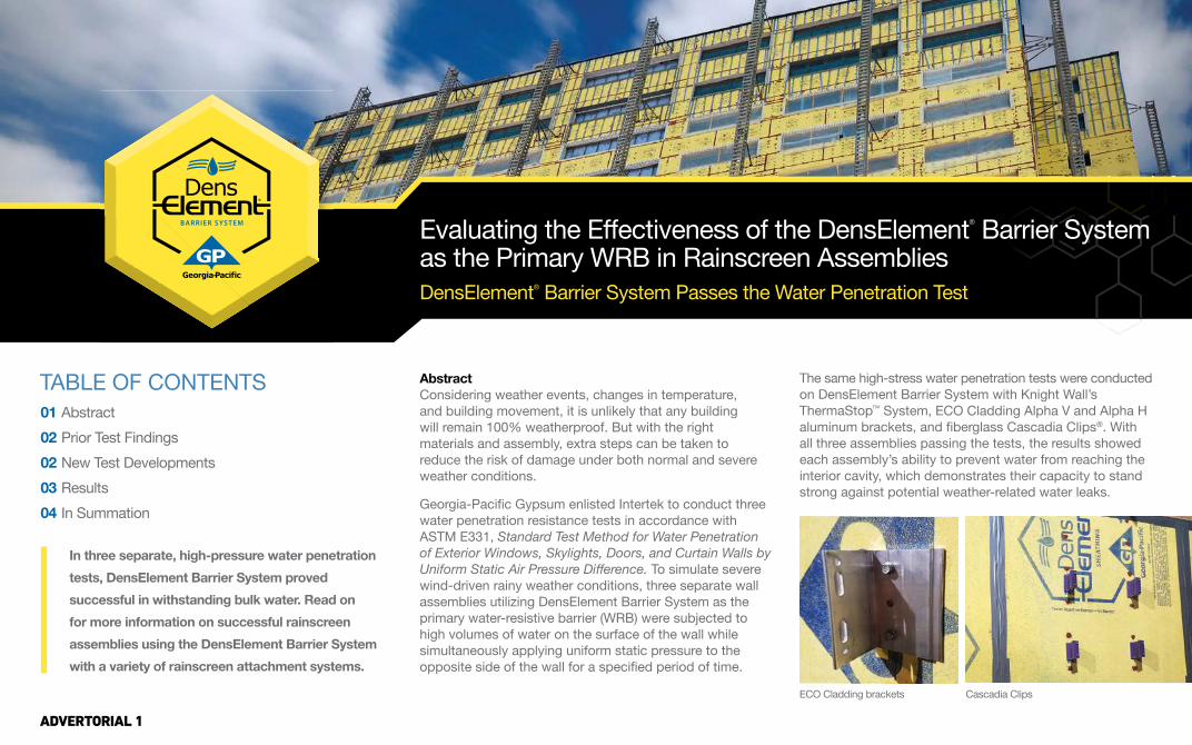
Evaluating the Effectiveness of the DensElement® Barrier System as the Primary WRB in Rainscreen AssembliesDensElement® Barrier System Passes the Water Penetration Test
In three separate, high-pressure water penetration tests, DensElement Barrier System proved successful in withstanding bulk water. Read on for more information on successful rainscreen assemblies using the DensElement Barrier System with a variety of rainscreen attachment systems.
01 Abstract02 Prior Test Findings 02 New Test Developments03 Results04 In Summation
TABLE OF CONTENTS AbstractConsidering weather events, changes in temperature, and building movement, it is unlikely that any building will remain 100% weatherproof. But with the right materials and assembly, extra steps can be taken to reduce the risk of damage under both normal and severe weather conditions.
Georgia-Pacific Gypsum enlisted Intertek to conduct three water penetration resistance tests in accordance with ASTM E331, Standard Test Method for Water Penetration of Exterior Windows, Skylights, Doors, and Curtain Walls by Uniform Static Air Pressure Difference. To simulate severe wind-driven rainy weather conditions, three separate wall assemblies utilizing DensElement Barrier System as the primary water-resistive barrier (WRB) were subjected to high volumes of water on the surface of the wall while simultaneously applying uniform static pressure to the opposite side of the wall for a specified period of time.
The same high-stress water penetration tests were conducted on DensElement Barrier System with Knight Wall’s ThermaStop™ System, ECO Cladding Alpha V and Alpha H aluminum brackets, and fiberglass Cascadia Clips®. With all three assemblies passing the tests, the results showed each assembly’s ability to prevent water from reaching the interior cavity, which demonstrates their capacity to stand strong against potential weather-related water leaks.
ECO Cladding brackets Cascadia Clips
ADVERTORIAL 1

Prior Test FindingsThe DensElement® Barrier System is a UL classified Type X gypsum sheathing, water-resistive barrier, and air barrier (WRB-AB) combination all in one—consisting of DensElement Sheathing and fluid-applied flashing (in this case, PROSOCO R-Guard® FastFlash® liquid flashing). When the sheathing joints, openings, penetrations, fasteners, and material transitions are properly sealed, the system meets uniform code requirements for use as a water-resistive barrier and air barrier.
Previous third-party cladding tests performed by RDH Building Sciences1 revealed that the way cladding fasteners were attached to the wall surface had the most bearing on how and why the assembly leaked under varying weather conditions. Prior demonstrations of multiple weather-resistive barrier systems including the DensElement Barrier System, a thin-mil fluid-applied WRB, and a thick-mil fluid-applied WRB were tested with various cladding attachment clips and Z Girt arrangements (applied both flange up and flange down).
Five 4x8’ test walls were constructed for the test, with a sixth wall panel constructed to demonstrate water penetration on an extruded polystyrene (XPS) insulation installed on the exterior and attached only with long screws. In these prior demonstrations, water was applied at a rate of 7.5 gallons per hour per square foot for 60 minutes at the following pressures: 0 Pa, 300 Pa, 600 Pa, 900 Pa, and 1,250 Pa (equaling 100 mile-per-hour sustained winds). These demonstrations pushed well beyond typical water volumes, pressures, and time durations to purposefully take the various assembles to failure and observe where and why leakage occurred to help determine best practices.
In these demonstrations, leaks occurred at the cladding attachment fasteners on all three WRB systems, as well as where the fasteners for the XPS insulation penetrated the sheathing. Whether the cladding attachment was fastened
through the DensElement Barrier System or through the fluid-applied WRB membrane over the glass mat sheathing made little difference. In all instances, the testing demonstrated that, if water found a penetration, it didn’t make a measurable difference whether the penetration was through DensElement Sheathing, thin-mil fluid-applied WRB, or thick-mil fluid-applied WRB.
In general, the assemblies did not leak if the cladding fasteners were installed tight to the sheathing or fluid-applied WRB surface—nor did the ones with the cladding fasteners installed with adequate spacing away from the wall surface to allow for water drainage behind the cladding attachment. Rather, most leaks occurred when the space between the WRB surface and cladding attachment was large enough for water to enter behind the attachment but not wide enough for the water to effectively drain in between.
New Test DevelopmentsEvaluated in accordance with ASTM E331-00(2016), Standard Test Method for Water Penetration of Exterior Windows, Skylights, Doors, and Curtain Walls by Uniform Static Air Pressure Difference, Intertek’s tests yielded positive results across all three separate demonstrations: DensElement Sheathing with Knight Wall’s ThermaStop System, ECO Cladding Alpha V and Alpha H aluminum brackets, and fiberglass Cascadia Clips®. In all instances, Georgia-Pacific Gypsum provided the initial test specimens, which Intertek will retain post-demonstration for a minimum of fouryears from completion.
All test walls were constructed using 18 ga steel studs spaced 16” on center. A sheet of nominal 5/8”-thick DensElement Sheathing was secured to the studs with #8 x 1-1/4” Phillips Bugle-Head fine thread self-drilling drywall screws spaced 8” on the center. The walls utilized two 2’x8’ Southern Yellow Pine boards on the jambs to facilitate the testing. All fasteners were spot-treated with PROSOCO
R-Guard®
FastFlash® liquid flashing. Each test used an overall area of 32 square feet, measuring 48” wide by 96” high.
In all instances, the systems were tested positioned flush against the DensElement Barrier System as well as with an intent for drainage. For the Knight Wall ThermaStop™ System test, the Knight Wall thermal break anchors were attached to the DensElement Sheathing using two #10 x 2-1/2” screws. Three Knight Wall ThermaStop brackets were attached flush to the sheathing, and three additional Knight Wall brackets were attached utilizing a 1/16” inverted U-shaped shim installed between the sheathing face and the bracket to allow for drainage.
For the ECO Cladding aluminum bracket test, the ECO Cladding aluminum anchors were attached to the DensElement Sheathing using two #8 x 1-1/2” screws. Three ECO Cladding Alpha V vertical brackets and three Alpha H horizontal brackets were attached flush to the sheathing. ECO Cladding subframe systems are designed to be installed without the need for additional shimming for drainage.
For the fiberglass Cascadia Clips test, the fiberglass Cascadia Clips were attached to the DensElement Sheathing using two #10 x 4-1/2” screws. Three purple 3” fiberglass Cascadia Clips were attached flush to the sheathing, and three additional Cascadia Clips were attached utilizing a 1/16” inverted U-shaped shim installed between the sheathing face and the clip to allow for drainage.
Test Specimen
Test Specimen Buck
Air seal between test buck and test wall(typically foam weatherstripping)
TE
ST
WA
LL
Air seal between testspecimen and test buck(typically silicone)
ADVERTORIAL 2
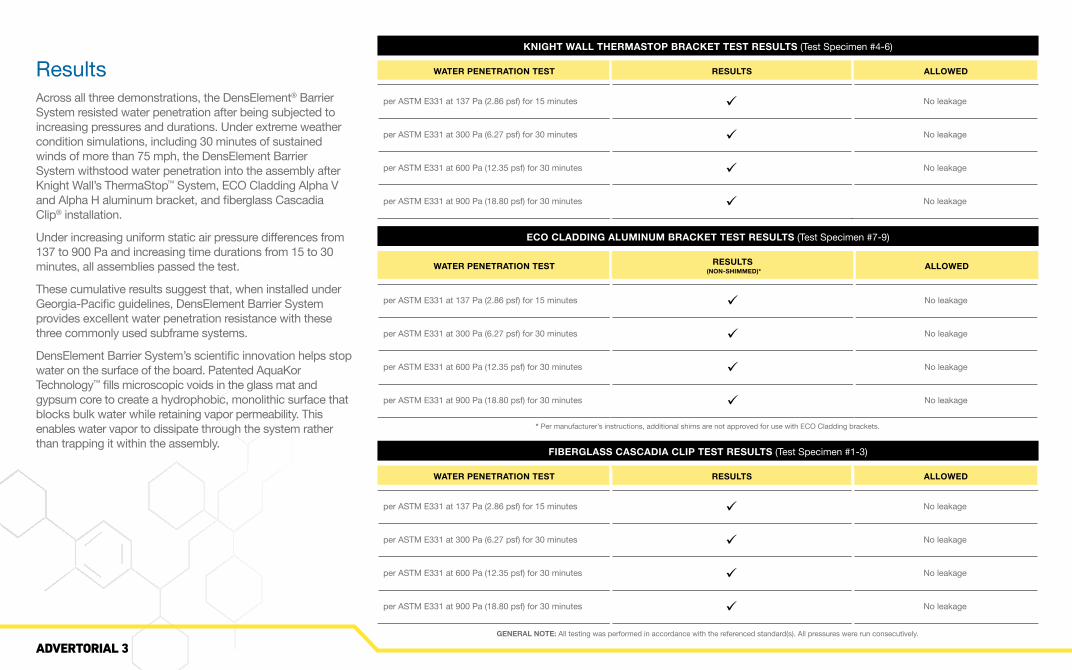
ResultsAcross all three demonstrations, the DensElement® Barrier System resisted water penetration after being subjected to increasing pressures and durations. Under extreme weather condition simulations, including 30 minutes of sustained winds of more than 75 mph, the DensElement Barrier System withstood water penetration into the assembly after Knight Wall’s ThermaStop™ System, ECO Cladding Alpha V and Alpha H aluminum bracket, and fiberglass Cascadia Clip® installation.
Under increasing uniform static air pressure differences from 137 to 900 Pa and increasing time durations from 15 to 30 minutes, all assemblies passed the test.
These cumulative results suggest that, when installed under Georgia-Pacific guidelines, DensElement Barrier System provides excellent water penetration resistance with thesethree commonly used subframe systems.
DensElement Barrier System’s scientific innovation helps stop water on the surface of the board. Patented AquaKor Technology™ fills microscopic voids in the glass mat and gypsum core to create a hydrophobic, monolithic surface that blocks bulk water while retaining vapor permeability. This enables water vapor to dissipate through the system rather than trapping it within the assembly.
GENERAL NOTE: All testing was performed in accordance with the referenced standard(s). All pressures were run consecutively.
* Per manufacturer’s instructions, additional shims are not approved for use with ECO Cladding brackets.
ECO CLADDING ALUMINUM BRACKET TEST RESULTS (Test Specimen #7-9)
WATER PENETRATION TEST RESULTS (NON-SHIMMED)* ALLOWED
per ASTM E331 at 137 Pa (2.86 psf) for 15 minutes ü No leakage
per ASTM E331 at 300 Pa (6.27 psf) for 30 minutes ü No leakage
per ASTM E331 at 600 Pa (12.35 psf) for 30 minutes ü No leakage
per ASTM E331 at 900 Pa (18.80 psf) for 30 minutes ü No leakage
FIBERGLASS CASCADIA CLIP TEST RESULTS (Test Specimen #1-3)
WATER PENETRATION TEST RESULTS ALLOWED
per ASTM E331 at 137 Pa (2.86 psf) for 15 minutes ü No leakage
per ASTM E331 at 300 Pa (6.27 psf) for 30 minutes ü No leakage
per ASTM E331 at 600 Pa (12.35 psf) for 30 minutes ü No leakage
per ASTM E331 at 900 Pa (18.80 psf) for 30 minutes ü No leakage
KNIGHT WALL THERMASTOP BRACKET TEST RESULTS (Test Specimen #4-6)
WATER PENETRATION TEST RESULTS ALLOWED
per ASTM E331 at 137 Pa (2.86 psf) for 15 minutes ü No leakage
per ASTM E331 at 300 Pa (6.27 psf) for 30 minutes ü No leakage
per ASTM E331 at 600 Pa (12.35 psf) for 30 minutes ü No leakage
per ASTM E331 at 900 Pa (18.80 psf) for 30 minutes ü No leakage
ADVERTORIAL 3

In Summation
1 “Cladding Attachments Put to the Test: Testing for Leakage Under Extreme Water and Wind” DensElement® Barrier System White Paper, Georgia-Pacific Gypsum: https://denselement.com/blog/technical-white-paper-cladding-attachments-put-to-the-test
2 Technical Bulletin: “Changes to the 2018 IBC: NFPA 285 requirement applicability to DensElement™ Barrier System” Georgia-Pacific Gypsum
Sources
These findings show that, in conjunction with the tested cladding attachment systems, DensElement® Barrier System provides excellent resistance against bulk water from wind-driven rain. When properly installed, DensElement Barrier System is a proven reliable WRB-AB across a variety of wall assembly designs, whereas misapplication and failure to properly install can result in unwanted leaks, water damage, and airflow. For this reason, pay extra close attention to proper detailing and installation, and follow Georgia-Pacific installation guidelines.
Unlike in this test situation, actual building scenarios should also include a cladding installed over the subframe, adding to the building envelope’s ability to deflect wind-driven rain. In such rainscreen assemblies, the drainage space that these subframes create between the sheathing and cladding helps to promote drainage and further mitigate the risks of bulk water entering the interior side of the wall assembly during a storm.
Rainscreen assemblies have grown in popularity for a number of reasons. Providing extra support against potentially damaging weather, rainscreen systems help manage moisture and protect the building’s structure from mold and other harmful effects—ultimately reducing maintenance needs.
With these testing results, designers can feel confident selecting DensElement Barrier System as their primary WRB-AB system of choice behind the rainscreen, particularly when using the Knight Wall ThermaStop™ Systems, ECO Cladding Alpha V and Alpha H aluminum brackets, or fiberglass Cascadia Clips® for the sub-frame.
Further simplifying the assembly process, compliance with NFPA 285 standard fire safety testing to evaluate the fire propagation characteristics of exterior wall assemblies is easier to achieve by using the DensElement Barrier System.2Since DensElement Sheathing is non-combustible, the requirements in IBC1402.5 for combustible water-resistive barriers, are not applicable and therefore DensElement Sheathing is exempt from NFPA 285 assembly testing. Therefore, this section does not require new testing to replace a current WRB-AB solution with DensElement Sheathing in any wall assembly that is currently NFPA 285 approved.
An effective WRB-AB in rainscreen assemblies, DensElement Barrier System is as versatile as it is reliable. Compatible across current leading cladding choices, the integrated sheathing system easily accommodates a variety of design styles—freeing designers to bridge creativity with constructability.
For both performance and design, DensElement Barrier System provides the versatility necessary to accommodate a variety of cladding options used with rainscreen, such as fiber cement, metal panels, terracotta panels, high-density laminate or composite panels, and more. For architects, combining your rainscreen assembly with DensElement Barrier System’s proven WRB-AB effectiveness and cladding versatility means flexibility and freedom of design. For everyone else, it means peace of mind that the assembly can stand strong when needed to perform.
Visit DensElement.com
ADVERTORIAL 4