Embed Size (px)
Citation preview

Sealing Large-Diameter Cast-Iron Pipe Joints Under Live Conditions
Quarterly Report
December 25, 2004 – March 24, 2005
By: Kiran M. Kothari
(Gas Technology Institute) and
Gerard T. Pittard (Maurer Technology Inc.)
April 2005
DE-FC22-02NT41316
GAS TECHNOLOGY INSTITUTE 1700 South Mount Prospect Road Des Plaines, Illinois 60018-1804
MAURER TECHNOLOGY INC.
13135 South Dairy Ashford, Suite 800 Sugar Land, Texas 77478-3686
DE-FC22-02NT41316 - ii - Gas Technology Institute Maurer Technology Inc.
Disclaimer
This report was prepared as an account of work sponsored by an agency of the United
States Government. Neither the United States Government nor any agency thereof, nor any of
their employees, makes any warranty, express or implied, or assumes any legal liability or
responsibility for the accuracy, completeness, or usefulness of any information, apparatus,
product, or process disclosed, or represents that its use would not infringe privately owned rights.
Reference herein to any specific commercial product, process, or service by trade name,
trademark, manufacturer, or otherwise does not necessarily constitute or imply its endorsement,
recommendation, or favoring by the United States Government or any agency thereof. The views
and opinions expressed herein do not necessarily state or reflect those of the United States
Government or any agency thereof.
DE-FC22-02NT41316 - iii - Gas Technology Institute Maurer Technology Inc.
Abstract
Utilities in the U.S. operate over 75,000 km (47,000 miles) of old cast-iron pipes for gas
distribution. The bell-and-spigot joints that connect pipe sections together tend to leak as these
pipes age. Current repair practices are costly and highly disruptive. The objective of this program
is to design, test and commercialize a robotic system capable of sealing multiple cast-iron bell
and spigot joints from a single pipe entry point. The proposed system will perform repairs while
the pipe remains in service by traveling through the pipe, cleaning each joint surface, and
installing a stainless-steel sleeve lined with an epoxy-impregnated felt across the joint. This
approach will save considerable time and labor, avoid traffic disruption, and eliminate any
requirement to interrupt service to customers (which would result in enormous expense to
utilities).
Technical challenges include: (1) repair sleeves must compensate for diametric variation
and eccentricity of old cast-iron pipes; (2) the assembly must travel long distances through pipes
containing debris; (3) the pipe wall must be effectively cleaned in the immediate area of the joint
to assure good bonding of the sleeve; and (4) an innovative bolt-on entry fitting is required to
conduct repair operations on live mains.
The development effort is divided into eleven tasks. Task 1 (Program Management) and
Task 2 (Establishment of Detailed Design Specifications) were completed previously. Task 3
(Design and Fabricate Ratcheting Stainless-Steel Repair Sleeves) has progressed to installing
prototype sleeves in test cast-iron pipe segments.
Efforts in the current quarter continued to be focused on Tasks 4–8. Highly valuable
lessons were learned from field tests of the 4-inch gas pipe repair robot in cast-iron pipe at Public
Service Electric & Gas. (These field tests were conducted and reported previously.) Several
design issues were identified which need to be implemented in both the small- and large-
diameter repair robots for cast-iron pipe to assure their commercial success. For Task 4 (Design,
Fabricate and Test Patch Setting Robotic Train), previous problems with bladder design and
elastomeric material expansion in the large mains were addressed. A new bladder based on a
DE-FC22-02NT41316 - iv - Gas Technology Institute Maurer Technology Inc.
commercially available design was obtained and tested with success. Minor improvements were
highlighted during patch-setting tests and are now being pursued.
For Task 5 (Design and Fabricate Pipe-Wall Cleaning Robot Train with Pan/Zoom/Tilt
Camera), the previous field tests showed clearly that, in mains with low gas velocities, it will be
necessary to improve the system’s capacity to remove debris from the immediate vicinity of the
bell and spigot joints. Otherwise, material removed by the cleaning flails (the flails were found to
be very effective in cleaning bell and spigot joints) falls directly to the low side of the pipe and
accumulates in a pile. This accumulation can prevent the sleeve from achieving a leak-free
repair. Similarly, it is also deemed necessary to design an assembly to capture existing service-
tap coupons and allow their removal from the inside of the pipe.
Task 6 (Design and Build Surface Control and Monitoring System) was previously
completed with the control and computer display functions being operated through LabVIEW.
However, this must now be revisited to add control routines for the coupon catcher that will be
added. This will most likely include a lift-off/place-on magnet translation function.
Task 7 (Design and Fabricate Large Diameter Live Access System) progressed to
completing the detailed design for a bolt-on entry fitting for 12-inch diameter cast-iron pipe in
the current quarter. The drilling assembly for cutting an access hole through the wall of the gas
main was also designed, along with a plug assembly to allow removing all tools from the live
main and setting a blind flange on the entry fitting prior to burial. These designs are described in
detail in the report.
Task 8 (System Integration and Laboratory Validation) continued with the development
of the robot module inter-connects and of a master LabVIEW-based system display and control
software.
DE-FC22-02NT41316 - v - Gas Technology Institute Maurer Technology Inc.
Table of Contents
Abstract......................................................................................................................................... iii
1. Introduction.......................................................................................................................... 1
2. Experimental ........................................................................................................................ 2 Experimental Objectives.........................................................................................................2 System Description.................................................................................................................2
3. Results and Discussion......................................................................................................... 5 Task 1 – Program Management ..............................................................................................5 Task 2 – Establishment of Detailed Design Specifications ....................................................5 Task 3 – Design/Fabricate Ratcheting Stainless-Steel Repair Sleeves...................................7 Task 4 – Design, Fabricate and Test Patch-Setting Robotic Train.......................................15 Task 5 – Design and Fabricate Pipe Wall Cleaning Robot Train with PZT Camera ...........19 Task 6 – Design and Build Surface Control and Monitoring System ..................................31 Task 7 – Design and Fabricate Large-Diameter Live Access System..................................32 Task 8 – System Integration and Laboratory Validation......................................................41 Task 9 – Field Testing and System Refinement ...................................................................41
Summary of Field Tests of Small Robotic System................................................. 42 Lessons Learned/Recommendations for Large-Diameter System ........................ 46
Task 10 – Benefits Analysis .................................................................................................47 Task 11 – Final Report .........................................................................................................47 Work Planned for Next Period..............................................................................................48
4. Conclusions......................................................................................................................... 49
5. References........................................................................................................................... 50

DE-FC22-02NT41316 - vi - Gas Technology Institute Maurer Technology Inc.
List of Tables
Table 1. Conventional Camera Wiring ......................................................................................... 20
Table 2. Surface Power Supply Specifications ............................................................................. 23
List of Figures
Figure 1. Pipe Wall Preparation Robot Train ................................................................................. 2
Figure 2. Camera’s View of Bell and Spigot Joint Seam ............................................................... 3
Figure 3. Patch-Setting Robot Train ............................................................................................... 4
Figure 4. Ratcheting Repair Sleeve ................................................................................................ 8
Figure 5. Coiled Diameter Comparison for 28 and 24 Gage .......................................................... 9
Figure 6. Repair Sleeve Components.............................................................................................. 9
Figure 7. Repair Sleeve with Epoxy Applied ............................................................................... 10
Figure 8. 12-Inch Cast Iron Pipe Sample...................................................................................... 10
Figure 9. Cast-Iron Pipe ID after Cleaning................................................................................... 11
Figure 10. Successfully Installed Repair Sleeve........................................................................... 11
Figure 11. Inflation Bladder.......................................................................................................... 12
Figure 12. Ruptured Inflation Bladder.......................................................................................... 12
Figure 13. New Inflation Bladder ................................................................................................. 13
Figure 14. Cast Iron Joint Tested for Leaks.................................................................................. 13
Figure 15. Bladder/Patch Assembly Hung in Joint....................................................................... 14
Figure 16. Ratchet Engagement After Patch Setting .................................................................... 15
Figure 17. Patch-Setting Module .................................................................................................. 17
Figure 18. Patch Setting Test ........................................................................................................ 17
Figure 19. Locking Ratchets on Patch .......................................................................................... 18
Figure 20. Pneumatic Inflation Circuit ......................................................................................... 18
Figure 21. PZT Camera................................................................................................................. 19
Figure 22. Camera Specifications ................................................................................................. 21
Figure 23. Conventional Camera Control Cable Design .............................................................. 23
Figure 24. Downhole Camera Control Circuit Board................................................................... 24
Figure 25. PZT Camera Power Supply ......................................................................................... 25
Figure 26. Camera Display and Control Software........................................................................ 25
DE-FC22-02NT41316 - vii - Gas Technology Institute Maurer Technology Inc.
Figure 27. Pipe Wall Cleaning Element ....................................................................................... 26
Figure 28. Pipe Wall Cleaning Test.............................................................................................. 27
Figure 29. Embedded Magnets to Collect Debris......................................................................... 28
Figure 30. Camera-Mounted Debris Arm..................................................................................... 29
Figure 31. Camera-Mounted Sweeper Arm.................................................................................. 30
Figure 32. Cleaning Elements Modified to Sweep Debris Forward............................................. 31
Figure 33. Cast Iron Entry Fitting (4-inch Prototype) .................................................................. 33
Figure 34. Cast Iron Entry Fitting (4-inch Prototype) .................................................................. 33
Figure 35. Bolt-On Fitting for Live Access into 12-in. Cast-Iron Mains ..................................... 35
Figure 36. Drilling Assembly for Cutting Access Hole in 12-in. Cast-Iron Mains ...................... 37
Figure 37. PVC Control Valve...................................................................................................... 38
Figure 38. Hole Saw for Cutting Access Hole in Gas Main......................................................... 39
Figure 39. Plug-Setting Assembly for Resealing 12-in. Cast-Iron Mains .................................... 40
Figure 40. Field Test Site.............................................................................................................. 42
Figure 41. Attaching Entry Fitting to Pipe Prior to Welding........................................................ 43
Figure 42. Magnet Assembly for Removing Filings .................................................................... 43
Figure 43. Moving through Entry Fitting ..................................................................................... 44
Figure 44. Successfully Set Patch at 93.7 ft.................................................................................. 45
Figure 45. Partially Engaged Patch at 58.6 ft ............................................................................... 45
Figure 46. Entry Fitting Ready for Burial..................................................................................... 46

DE-FC22-02NT41316 - 1 - Gas Technology Institute Maurer Technology Inc.
1. Introduction
Utilities in the U.S. operate over 75,000 km (47,000 miles) of old cast-iron pipes for gas
distribution. Most of this pipe is in highly urbanized areas and its replacement is prohibitively
expensive. While the cast-iron pipe itself generally retains acceptable mechanical competency,
the joints, which are bell-and-spigot design, tend to leak. Current repair practices are to either:
(1) excavate and expose each joint and encapsulate it externally; or (2) take the line out of
service and apply repair sleeves or cured-in-place liners. Both methods are costly and highly
disruptive.
The objective of this program is to design, test and commercialize a robotic system
capable of sealing multiple cast-iron bell and spigot joints from a single pipe entry point. The
proposed system will perform repairs while the pipe remains in service by traveling through the
pipe, cleaning each joint surface, and attaching a stainless-steel sleeve lined with an epoxy-
impregnated felt across the joint. This approach will save considerable time and labor, avoid
traffic disruption, and eliminate the requirement to interrupt service, which results in enormous
expense to utilities and considerable inconvenience to customers.
This development effort represents an aggressive expansion of existing technologies.
Applying this technique inside large-diameter cast-iron pipes poses a number of technical
challenges, among them: (1) repair sleeves must compensate for diametric variation and
eccentricity of cast-iron pipes; (2) the assembly must travel long distances through pipes having
significant levels of debris; (3) the pipe wall must be effectively cleaned in the immediate area of
the joint to assure good bonding of the sleeve; (4) an innovative bolt-on entry fitting is required
to conduct repair operations on live mains; (5) coiled-tubing equipment must be designed to
optimize push distance from a single pipe entry point.
DE-FC22-02NT41316 - 2 - Gas Technology Institute Maurer Technology Inc.
2. Experimental
Experimental Objectives
The objective of this development program is to design, test and commercialize a robotic
system capable of sealing multiple cast-iron bell and spigot joints from a single pipe entry point.
The proposed system will perform repairs while the pipe remains in service by traveling through
the pipe, cleaning each joint surface, and attaching a stainless-steel sleeve lined with an epoxy-
impregnated felt across the joint. This approach will save considerable time and labor, avoid
traffic disruption, and eliminate any requirement to interrupt service to customers (which would
result in enormous expense to utilities).
System Description
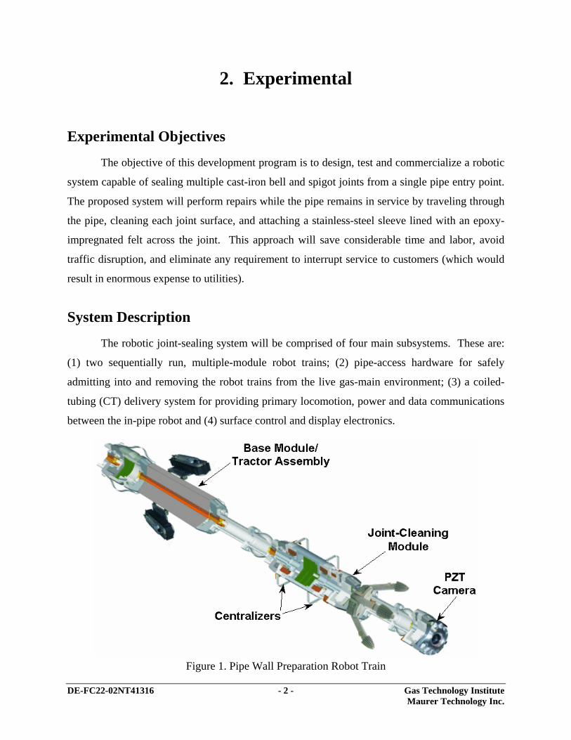
The robotic joint-sealing system will be comprised of four main subsystems. These are:
(1) two sequentially run, multiple-module robot trains; (2) pipe-access hardware for safely
admitting into and removing the robot trains from the live gas-main environment; (3) a coiled-
tubing (CT) delivery system for providing primary locomotion, power and data communications
between the in-pipe robot and (4) surface control and display electronics.
Figure 1. Pipe Wall Preparation Robot Train
DE-FC22-02NT41316 - 3 - Gas Technology Institute Maurer Technology Inc.
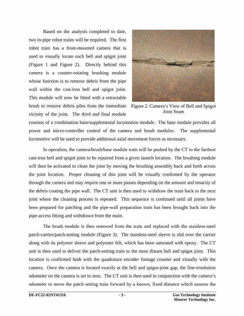
Based on the analysis completed to date,
two in-pipe robot trains will be required. The first
robot train has a front-mounted camera that is
used to visually locate each bell and spigot joint
(Figure 1 and Figure 2). Directly behind this
camera is a counter-rotating brushing module
whose function is to remove debris from the pipe
wall within the cast-iron bell and spigot joint.
This module will now be fitted with a retractable
brush to remove debris piles from the immediate
vicinity of the joint. The third and final module
consists of a combination base/supplemental locomotion module. The base module provides all
power and micro-controller control of the camera and brush modules. The supplemental
locomotive will be used to provide additional axial movement forces as necessary.
In operation, the camera/brush/base module train will be pushed by the CT to the farthest
cast-iron bell and spigot joint to be repaired from a given launch location. The brushing module
will then be activated to clean the joint by moving the brushing assembly back and forth across
the joint location. Proper cleaning of this joint will be visually confirmed by the operator
through the camera and may require one or more passes depending on the amount and tenacity of
the debris coating the pipe wall. The CT unit is then used to withdraw the train back to the next
joint where the cleaning process is repeated. This sequence is continued until all joints have
been prepared for patching and the pipe-wall preparation train has been brought back into the
pipe-access fitting and withdrawn from the main.
The brush module is then removed from the train and replaced with the stainless-steel
patch-carrier/patch-setting module (Figure 3). The stainless-steel sleeve is slid over the carrier
along with its polymer sleeve and polyester felt, which has been saturated with epoxy. The CT
unit is then used to deliver the patch-setting train to the most distant bell and spigot joint. This
location is confirmed both with the quadrature encoder footage counter and visually with the
camera. Once the camera is located exactly at the bell and spigot-joint gap, the fine-resolution
odometer on the camera is set to zero. The CT unit is then used in conjunction with the camera’s
odometer to move the patch setting train forward by a known, fixed distance which assures the
Figure 2. Camera’s View of Bell and Spigot
Joint Seam

DE-FC22-02NT41316 - 4 - Gas Technology Institute Maurer Technology Inc.
patch is properly aligned with the bell and spigot joint. A control command is then issued from
the surface unit to the base unit to release nitrogen from a stainless-steel pressure vessel on-board
the patch-setting module into its expandable rubber bladder. This causes the bladder to inflate
and locks the stainless-steel sleeve into position via its interlocking, ratcheting barbs. The epoxy
is allowed to cure and reaches full strength within 12 hours. During the interim, a gas-tight seal
is assured by the polymer sleeve which has been energized against the joint by the hoop stress of
the stainless-steel sleeve. (Note: The volume and rate at which the nitrogen is bled from the
inflation bladder results in no appreciable dilution of the BTU quality of the natural gas.)
Figure 3. Patch-Setting Robot Train
DE-FC22-02NT41316 - 5 - Gas Technology Institute Maurer Technology Inc.
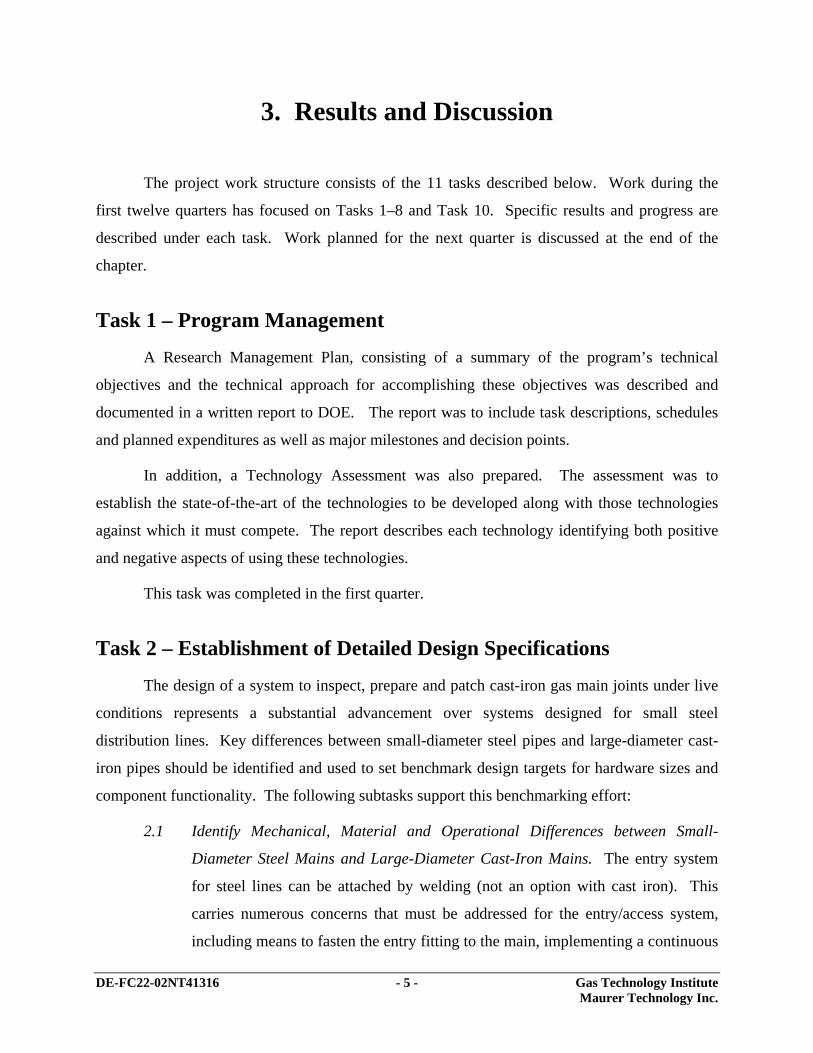
3. Results and Discussion
The project work structure consists of the 11 tasks described below. Work during the
first twelve quarters has focused on Tasks 1–8 and Task 10. Specific results and progress are
described under each task. Work planned for the next quarter is discussed at the end of the
chapter.
Task 1 – Program Management
A Research Management Plan, consisting of a summary of the program’s technical
objectives and the technical approach for accomplishing these objectives was described and
documented in a written report to DOE. The report was to include task descriptions, schedules
and planned expenditures as well as major milestones and decision points.
In addition, a Technology Assessment was also prepared. The assessment was to
establish the state-of-the-art of the technologies to be developed along with those technologies
against which it must compete. The report describes each technology identifying both positive
and negative aspects of using these technologies.
This task was completed in the first quarter.
Task 2 – Establishment of Detailed Design Specifications
The design of a system to inspect, prepare and patch cast-iron gas main joints under live
conditions represents a substantial advancement over systems designed for small steel
distribution lines. Key differences between small-diameter steel pipes and large-diameter cast-
iron pipes should be identified and used to set benchmark design targets for hardware sizes and
component functionality. The following subtasks support this benchmarking effort:
2.1 Identify Mechanical, Material and Operational Differences between Small-
Diameter Steel Mains and Large-Diameter Cast-Iron Mains. The entry system
for steel lines can be attached by welding (not an option with cast iron). This
carries numerous concerns that must be addressed for the entry/access system,
including means to fasten the entry fitting to the main, implementing a continuous

DE-FC22-02NT41316 - 6 - Gas Technology Institute Maurer Technology Inc.
seal with long-term reliability, and designing an entry system that can tolerate
settling of the joints over time and provide sufficient reinforcement of stiffness of
the main both during and after the repair.
2.2 Prototype Size Selection. Large-diameter cast-iron gas mains in the U.S. range in
size from 20 to 91 cm (8 to 36 in.) nominal diameter. Since there will obviously
be size-specific requirements to be addressed, a size must be selected for the
prototype system. This will be done through discussions with the GTI
Distribution Task Group (DTG) Advisors. It is expected that the selected size
will be either 20 cm (8 in.) or 30 cm (12 in.) since 30 cm and smaller sizes
combined represent 95.5% of cast-iron mains in the US.
2.3 Perform Pushing/Buckling Tradeoff Analyses. Based on candidate coiled-tubing
(CT) products, efforts will be aimed to define “sensitive” design targets points for
hardware that will be inserted into the cast-iron main. These will include drag
forces, weights of the components, bending requirements on the CT, and stiffness
concerns for flexible joints between the required hardware modules on the robot
train.
Deliverables for this task include a list of performance and size specifications that
provide the basis for follow-on detailed design activities.
Mechanical, material and operational differences between small-diameter steel mains and
large-diameter cast-iron mains have been defined. Primary challenges posed by large diameter
cast-iron mains involve larger variation in inside pipe dimensions (being addressed by use of a
ratcheting sleeve design that can effectively lock into placed over a range of pipe sizes); presence
of more debris (being addressed through the use of much more aggressive wall cleaning
equipment and the possible use of a plow to move debris away from the bell and spigot joint
area); and the fact that the entry fitting for cast iron must be a bolt-on design and entry hole size
should be minimized to prevent cracking of the brittle cast iron.
Discussions held with several utilities during the second quarter, including KeySpan
Energy, Consolidated Edison and Public Service Electric & Gas, showed that utilities prefer the
first prototype be sized for operations inside nominal 12-inch diameter cast-iron pipes. As a
result, design efforts are focused on producing detailed designs for the entry fitting, cleaning

DE-FC22-02NT41316 - 7 - Gas Technology Institute Maurer Technology Inc.
elements and repair sleeves for this size application. A prototype wall-cleaning device and a bolt-
on entry fitting for 12-inch cast-iron mains have been designed.
The CT pushing/buckling analysis was completed in the first quarter. It is expected that
this analysis will be briefly revisited after the final weights and drag loads on each robotic
element are finished.
Task 3 – Design/Fabricate Ratcheting Stainless-Steel Repair Sleeves
Existing repair sleeves are designed for application under “dead” main conditions (i.e.,
the mains are not in service and there is no internal pressure present). These sleeves cannot
tolerate internal pressure. With current designs, a pressure gradient would displace the sealing
epoxy prior to curing, thereby creating leak paths. In addition, repair sleeves for large cast-iron
mains must be tolerant of misalignments in the bell and spigot joints. Such misalignment can
prevent thorough sealing when using existing designs of repair sleeves.
The sleeve must conform tightly to the interior shape of the joint. A repair sleeve with
ratcheting features will make this possible. Designs will be tested on cast-iron pipe samples (as
available). Test sample joints will be specially fabricated with intentional misalignments to
further test as necessary. To address these critical requirements, work efforts will be directed to:
3.1 Determine Geometrical Spacing of Interlocking Barbs. This spacing design must
allow sufficient adjustment for misalignment of bell and spigot segments of the
joints. Samples will be obtained to perform testing with misalignment conditions
observed in the field.
3.2 Perform Sensitivity Analyses. Sealing design parameters must be evaluated with
respect to sleeve geometry and the amount of compression (“squeeze”) on the
patch during application. Patches must be able to lock into place while tolerating
misalignment as well as lock in such a fashion to provide ample sealing over all
required surfaces. Other aspects to be examined include the design thickness of
the felt and the impact of this thickness on sealing effectiveness.
There will be two iterations of the interlocking sleeve design. The first design will be
thoroughly tested and evaluated. After any augmentations are made to the first design, a second

DE-FC22-02NT41316 - 8 - Gas Technology Institute Maurer Technology Inc.
set will be fabricated and evaluated. The deliverables for this task will be the final design of the
ratcheting repair sleeves, complete with mechanical drawings and specifications for fabrication
and assembly. A sufficient number (about eight) will be built following the second design
iteration.
During the first quarter, the first design iteration for one type of the repair sleeves under
consideration was prepared. This design is based on modifying existing sealing products from a
commercial sleeve manufacturer (Link-Pipe Inc.) so that their sleeves can operate in pressurized
gas mains, provide a redundant seal, and minimize their overall diameter before they are
expansion-set across the bell and spigot joint. The current commercial sleeve design from the
manufacturer does not work in pressurized mains and has only one seal method. In addition, the
project approach is to minimize sleeve
diameter for simplifying launching of the
sleeve into the main and allowing it to ride
off the bottom of the main (invert) to
minimize its contamination with debris.
Figure 4 illustrates the critical
design features. A 28-gage, corrugated
stainless-steel sleeve (316 SS) is used as
the innermost member. Its function is to
provide a mechanical means for energizing
the urethane seal sleeve against the cast-iron wall to form the first leak seal and to allow the
epoxy-saturated polyester carrier to cure to form a second (redundant) leak seal. The sleeve gage
(28) is a reduction from the 24 gage normally used. Its use will enable the sleeve to be coiled in a
smaller diameter without yielding. Preliminary analysis indicates that the design can be rolled
into a diameter of about 55% of the pipe ID versus 75 % of the pipe ID for the 24-gage thickness
sleeves (Figure 5). Corrugations, consisting of folds spaced on 1-inch centers, improve the
structural stiffness of the device so it does not deform during setting.
The most obvious visual trait of the urethane seal sleeve is its grooves (ribs). This new
design compensates for the axial shortening that would otherwise occur if a non-ribbed sleeve
were allowed to radially expand significantly. The end elements feature increased thickness and
Figure 4. Ratcheting Repair Sleeve

DE-FC22-02NT41316 - 9 - Gas Technology Institute Maurer Technology Inc.
act as an O-ring once the seal is
expanded. Their thickness, coupled
with low durometer, should provide an
effective pressure seal across a range
of cast-iron surface conditions as well
as easily compensate for variation in
pipe ID. AutoCAD machine drawings
of the molds to produce these sleeves
in both 8- and 12-inch sizes were
prepared.
The final element of the design is a polyester jacket which will carry the epoxy resin. At
present, a thixotropic epoxy is being considered that provides about 1 hour of working time
before curing begins to create the final seal.
Work has progressed to the fabrication and testing of the second-generation 12-inch
repair sleeves featuring ratchets and polyurethane seal sleeves. Components of the most recent
sleeve design are shown in Figure 6. The sleeve measures 13 inches long x 7.75 inches diameter
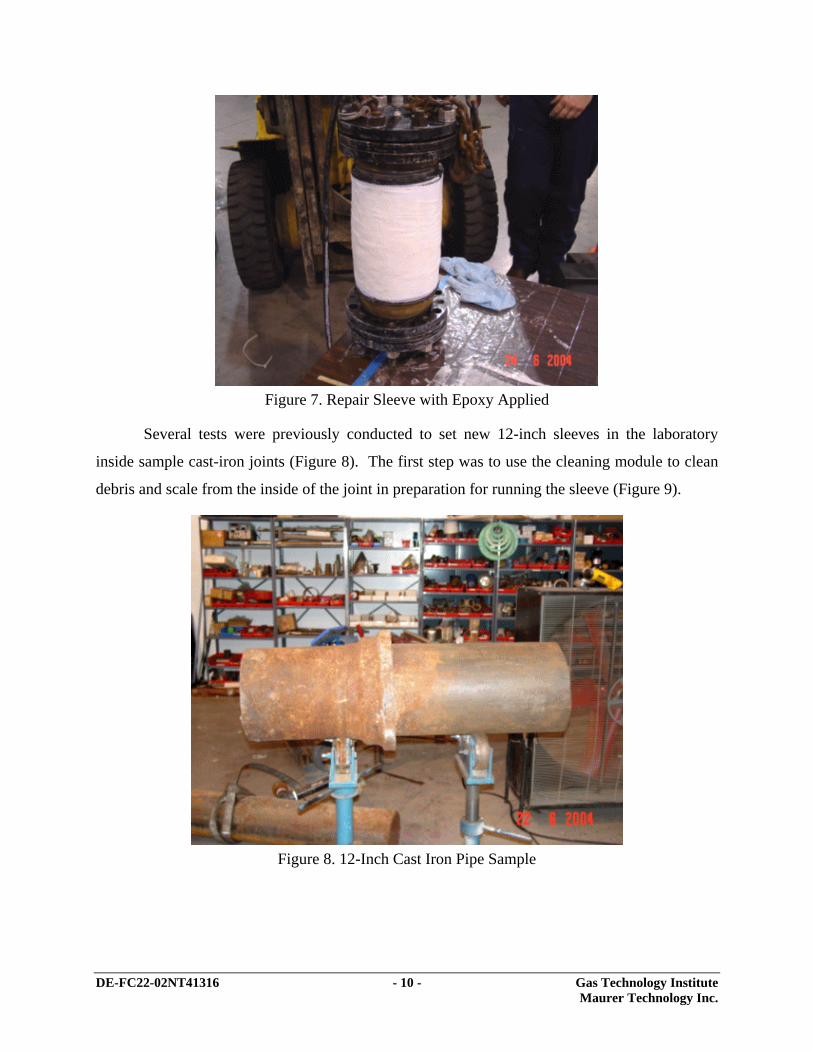
in its collapsed (unset) state. Figure 7 shows a sleeve with epoxy applied ready for insertion into
the gas main via the inflation module.
Figure 6. Repair Sleeve Components
Figure 5. Coiled Diameter Comparison for
28 and 24 Gage
DE-FC22-02NT41316 - 10 - Gas Technology Institute Maurer Technology Inc.
Figure 7. Repair Sleeve with Epoxy Applied
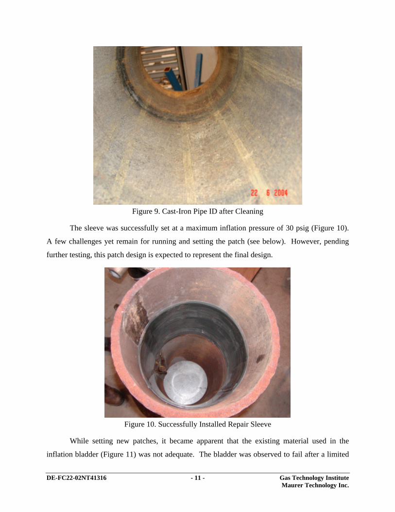
Several tests were previously conducted to set new 12-inch sleeves in the laboratory
inside sample cast-iron joints (Figure 8). The first step was to use the cleaning module to clean
debris and scale from the inside of the joint in preparation for running the sleeve (Figure 9).
Figure 8. 12-Inch Cast Iron Pipe Sample
DE-FC22-02NT41316 - 11 - Gas Technology Institute Maurer Technology Inc.
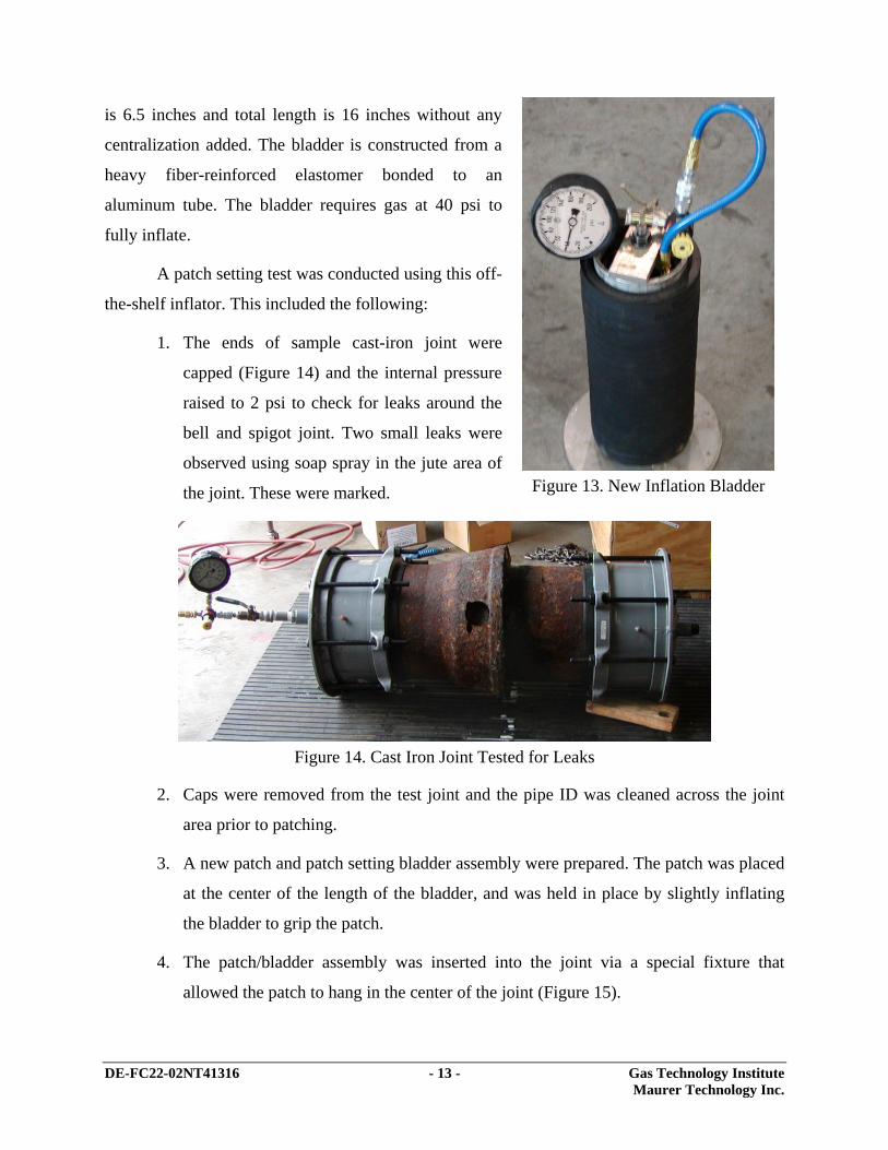
Figure 9. Cast-Iron Pipe ID after Cleaning
The sleeve was successfully set at a maximum inflation pressure of 30 psig (Figure 10).
A few challenges yet remain for running and setting the patch (see below). However, pending
further testing, this patch design is expected to represent the final design.
Figure 10. Successfully Installed Repair Sleeve
While setting new patches, it became apparent that the existing material used in the
inflation bladder (Figure 11) was not adequate. The bladder was observed to fail after a limited

DE-FC22-02NT41316 - 12 - Gas Technology Institute Maurer Technology Inc.
number of inflation cycles along the line where the end of the inner sleeve contacts the gum
rubber. Options for modifying the bladder include using another compound having a higher
tensile strength, or further increasing the thickness of the gum rubber. Figure 12 shows a failed
gum rubber sleeve. Alternatives for modifying the gum rubber sleeve were investigated.
Figure 11. Inflation Bladder
Figure 12. Ruptured Inflation Bladder
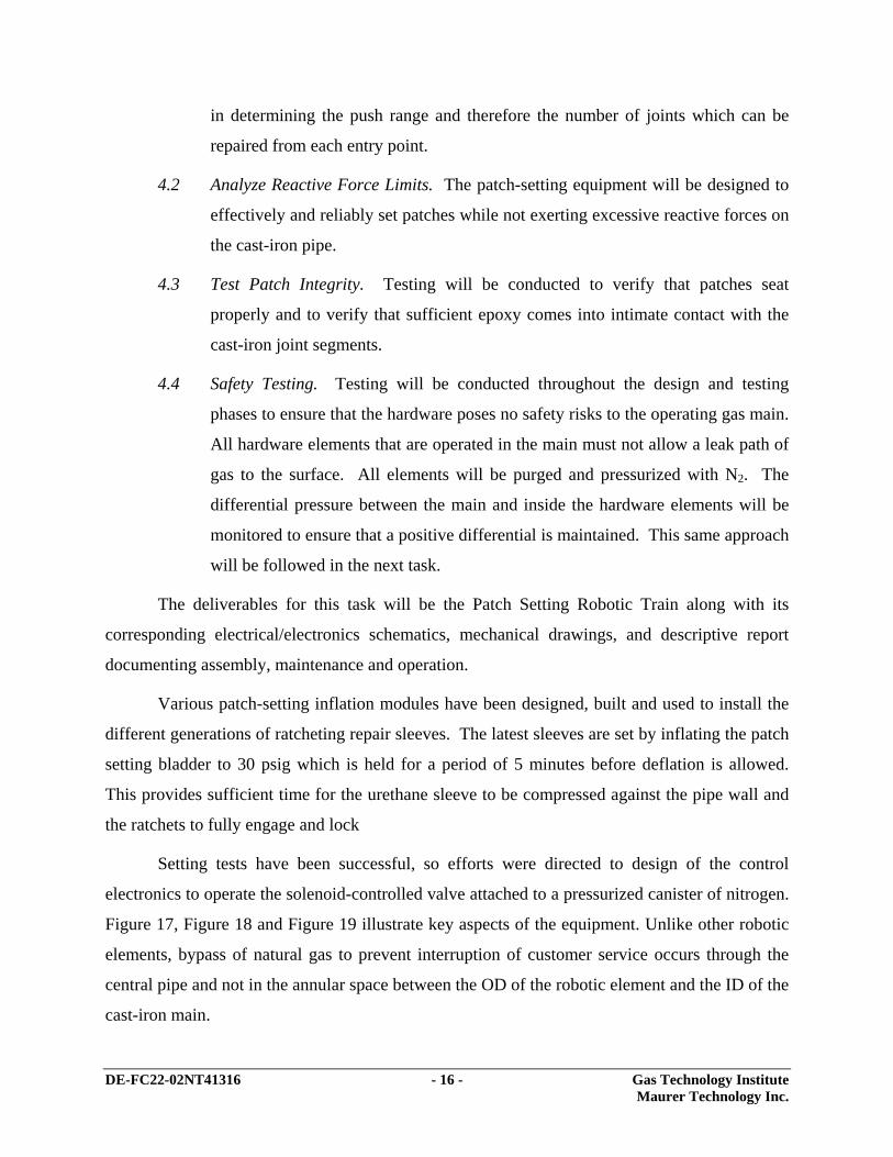
During the current quarter, the team acquired and tested a commercial inflation bladder
from the company that manufactures the patch assemblies (Figure 13). Initial OD of this system
DE-FC22-02NT41316 - 13 - Gas Technology Institute Maurer Technology Inc.
is 6.5 inches and total length is 16 inches without any
centralization added. The bladder is constructed from a
heavy fiber-reinforced elastomer bonded to an
aluminum tube. The bladder requires gas at 40 psi to
fully inflate.
A patch setting test was conducted using this off-
the-shelf inflator. This included the following:
1. The ends of sample cast-iron joint were
capped (Figure 14) and the internal pressure
raised to 2 psi to check for leaks around the
bell and spigot joint. Two small leaks were
observed using soap spray in the jute area of
the joint. These were marked.
Figure 14. Cast Iron Joint Tested for Leaks
2. Caps were removed from the test joint and the pipe ID was cleaned across the joint
area prior to patching.
3. A new patch and patch setting bladder assembly were prepared. The patch was placed
at the center of the length of the bladder, and was held in place by slightly inflating
the bladder to grip the patch.
4. The patch/bladder assembly was inserted into the joint via a special fixture that
allowed the patch to hang in the center of the joint (Figure 15).
Figure 13. New Inflation Bladder

DE-FC22-02NT41316 - 14 - Gas Technology Institute Maurer Technology Inc.
Figure 15. Bladder/Patch Assembly Hung in Joint
5. The bladder was inflated to 40 psi (maximum recommended pressure). The bladder
required over 10 minutes to completely inflate.
6. Distinct clicking noises were heard during inflation as the ratchets engaged deeper.
After inflation was complete, the inflator was left in place for an additional five
minutes.
7. Pressure was released on the inflator bladder. The inflation bladder was removed
from the cast-iron joint. The caps were again placed on the joint and the inside
volume was pressurized to 2 psi. Locations of previous leaks were inspected and
tested with soap spray. No leaks were detected.
After the tests were completed, a careful inspection of the set patch indicated that the two
outermost rows of ratchets did not engage as deeply as the two inner rows (Figure 16). It
appeared that the inflation bladder needs to be about two inches longer on each end to fully
engage the patch sleeve ratchets as currently configured.

DE-FC22-02NT41316 - 15 - Gas Technology Institute Maurer Technology Inc.
Figure 16. Ratchet Engagement After Patch Setting
Even though the patch set successfully and all leaks were sealed, it was desired to modify
the patch or bladder design to allow deeper ratcheting toward the outer edges of the patch. Since
use of a standard bladder design is preferred, changes to bladder design were avoided. Another
solution was conceived and pursued. The patch manufacturer was asked to stamp two additional
rows of ratchets into the sleeve midway between the existing rows. A prototype sleeve with this
modification (a total of six rows of ratchets) was ordered and will be tested soon.
The relatively long time required to inflate the bladder (10 minutes) is due to resistance
from the sleeve as it opens outward (i.e., unwinds). Dry lubrication may help to decrease this
time requirement.
Task 4 – Design, Fabricate and Test Patch-Setting Robotic Train
To set patches under live main conditions, the patching hardware must meet several key
criteria. It must be able to be inserted and removed from the gas mains without damage. It must
be able to be translated using coiled tubing (CT). Its physical form must not impede gas flow
through the main (thereby maintaining gas delivery to customers). Lastly, it must be able to set
patches with high reliability. To support the design, the following subtasks will be undertaken:
4.1 Analyze Weight and Drag. Hardware must be designed to perform required
patch-setting functions while minimizing weight and drag, as these are key drivers
DE-FC22-02NT41316 - 16 - Gas Technology Institute Maurer Technology Inc.
in determining the push range and therefore the number of joints which can be
repaired from each entry point.
4.2 Analyze Reactive Force Limits. The patch-setting equipment will be designed to
effectively and reliably set patches while not exerting excessive reactive forces on
the cast-iron pipe.
4.3 Test Patch Integrity. Testing will be conducted to verify that patches seat
properly and to verify that sufficient epoxy comes into intimate contact with the
cast-iron joint segments.
4.4 Safety Testing. Testing will be conducted throughout the design and testing
phases to ensure that the hardware poses no safety risks to the operating gas main.
All hardware elements that are operated in the main must not allow a leak path of
gas to the surface. All elements will be purged and pressurized with N2. The
differential pressure between the main and inside the hardware elements will be
monitored to ensure that a positive differential is maintained. This same approach
will be followed in the next task.
The deliverables for this task will be the Patch Setting Robotic Train along with its
corresponding electrical/electronics schematics, mechanical drawings, and descriptive report
documenting assembly, maintenance and operation.
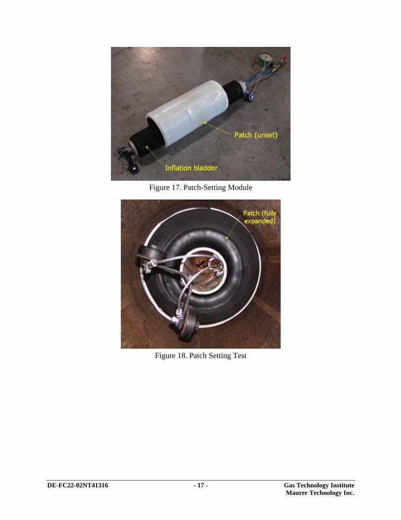
Various patch-setting inflation modules have been designed, built and used to install the
different generations of ratcheting repair sleeves. The latest sleeves are set by inflating the patch
setting bladder to 30 psig which is held for a period of 5 minutes before deflation is allowed.
This provides sufficient time for the urethane sleeve to be compressed against the pipe wall and
the ratchets to fully engage and lock
Setting tests have been successful, so efforts were directed to design of the control
electronics to operate the solenoid-controlled valve attached to a pressurized canister of nitrogen.
Figure 17, Figure 18 and Figure 19 illustrate key aspects of the equipment. Unlike other robotic
elements, bypass of natural gas to prevent interruption of customer service occurs through the
central pipe and not in the annular space between the OD of the robotic element and the ID of the
cast-iron main.
DE-FC22-02NT41316 - 17 - Gas Technology Institute Maurer Technology Inc.
Figure 17. Patch-Setting Module
Figure 18. Patch Setting Test

DE-FC22-02NT41316 - 18 - Gas Technology Institute Maurer Technology Inc.
Figure 19. Locking Ratchets on Patch
The patch-setting control system consists of a solenoid valve which allows the air
pressure to be admitted into the inflation bladder under computer control, a pressure chamber for
storing the nitrogen charge and pressure relief valves which allow adjustment of the charge
pressure to compensate for differences in the gas main operating pressure. Figure 20 summarizes
the pneumatic inflation circuit.
Figure 20. Pneumatic Inflation Circuit

DE-FC22-02NT41316 - 19 - Gas Technology Institute Maurer Technology Inc.
Task 5 – Design and Fabricate Pipe Wall Cleaning Robot Train with PZT Camera
Cast-iron gas mains operate at much lower pressure than their steel counterparts;
consequently, their interior conditions are often
quite different. Lower pressures in cast-iron
mains can allow moisture and debris to seep in
through leak points if sufficient hydrostatic head
(from the local water table) is present outside of
the main. In addition, the interior of cast iron is
generally not as smooth as steel, due to corrosion
and surface roughness from the original
manufacturing process. Other complications arise
due to deposits of tar residue in the bottom of the
main. The source of this residue dates back to
when mains carried “manufactured” gas. The
molecularly heavier tars and other impurities
settled out into the bottom of the mains and then
combined with particulate matter to form a hard
crust. This crust is porous and must therefore be
removed prior to applying a patch repair sleeve.
In addition, the pipe ID must be clean and smooth
to ensure that the epoxy adheres properly to the cast iron. To address these challenges, the
following subtasks are being completed in Task 5:
5.1 Analyze Deposits and Scales. The expected deposits in typical cast-iron mains
will be investigated and the most effective way(s) to remove them defined.
5.2 Design Equipment to Identify Deposit Types via Camera. Design/select camera
and lighting systems to provide sufficient performance to make positive
identification and then select the appropriate means to prepare the surface.
Figure 21. PZT Camera
Camera
Lights

DE-FC22-02NT41316 - 20 - Gas Technology Institute Maurer Technology Inc.
5.3 Design and Test Cleaning/Brushing Equipment. Equipment will be designed to
remove scales and deposits found inside cast-iron pipe. Tests will be conducted
on line pipe to ensure that appropriate cleaning is performed by the system.
The deliverables for this task will be the Prototype Pipe Wall Cleaning Robot Train with
Pan/Zoom/Tilt (PZT) Camera along with its corresponding electrical/electronics schematics,
mechanical drawings, and descriptive report documenting assembly, maintenance and operation.
The analysis of different PZT cameras was completed in the second quarter and a
preferred design selected. The camera (Figure 21) measures 4 inches OD x 10.5 inches overall
length. It features 270° of tilt, 340° of pan and a 72:1 zoom ratio. Its eight, high intensity argon
lights were found to provide excellent illumination in tests conducted inside sealed 12- and 24-
inch pipes. Specifications are summarized in Figure 22. In normal operations where the camera
tether is 100 feet or less, a 16-conductor bundle is used as defined in Table 1.
Table 1. Conventional Camera Wiring ITEM FUNCTION 75 ohm coax Video (+) core, Video (-) shield 18 awg, red Camera Power (+) 18 awg, black Camera Power (ground) 18 awg, yellow Pan (+) 18 awg, orange Pan (-) 18 awg, white Tilt (+) 18 awg, blue Tilt (-) 18 awg, pink and green Camera Lights (+) 18 awg, purple and clear Camera Lights (-) 22 awg, grey Camera Function/Focus (+) 22 awg, black Camera Function/ground 22 awg, tan AF indicator/Focus (-) 22 awg, purple 2.5”/4.0” Indictaor 18 awg, brown Camera Fade

DE-FC22-02NT41316 - 21 - Gas Technology Institute Maurer Technology Inc.
Figure 22. Camera Specifications
Pan/Zoom/Tilt (PZT) Camera
Camera in Pipe at
Joint
Camera Controller
Camera Controller
Camera in Pipe at Joint
Camera’s View of Joint Seam
Standard Camera Controller
SPECIFICATIONS
Pick-up Element: ¼” CCD Lens: 72:1 Zoom (18X Optical, 4X Digital) Resolution: > 460 TV Lines Illumination: 3 lux Horizontal FOV: 48° wide, 2.7° tele (in air)
Lights: 8 x 6 W Argon lights, variable intensity Pan Range: 340° Mechanical, (360° Visible) Tilt Range: > 270° Power Requirements: 110/220 VAC Pan/Tilt Control: Proportional

DE-FC22-02NT41316 - 22 - Gas Technology Institute Maurer Technology Inc.
Use of a 16-conductor bundle becomes inefficient inside 1000 ft of small-diameter CT.
A preferred approach is to power and operate the camera using seven wires. Two of these will
be large-diameter twisted pair to supply high-voltage DC, four smaller wires to transmit digital
control signals, and one to transmit video images. This change requires development of a
microcontroller-operated switching power supply inside the robot base module and a data-
acquisition system at the surface to convert the analog proportional joystick controls for pan,
zoom, tilt, light intensity, etc. to digital signals.
During a previous quarter, the robotic system’s pan/zoom/tilt camera control electronics
and operating software were developed and implemented in both the surface and downhole
modules. Camera surface hardware consists of a 95-Volt DC power supply capable of sourcing
up to 2.1 Amps for operating camera illumination, lenses and physical orientation within the
pressurized gas main, a personal computer having an RS-485 bidirectional communications port,
a 15-inch color monitor for displaying camera images and a rack-mounted video cassette
recorder. Downhole hardware consists of the camera head and the camera control electronics.
The latter is housed inside the robotics base module that is common for all robotic trains.
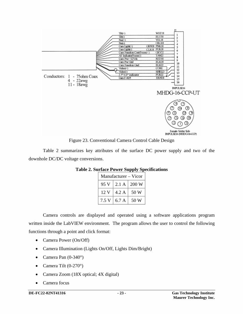
DC power is supplied to the downhole camera control electronics over an 18-gage
twisted pair of conductors. Use of a single high-voltage power source at the surface was chosen
over individually supplying all of the regulated voltages needed to operate the camera for two
important reasons: (1) it is a highly efficient means of transferring electrical power down the
long cables residing inside the steel coiled tubing and (2) it minimizes the total number of
conductors required for the umbilical. The current design employs a total of seven wires to
operate the camera. These include two wires for electrical power, four wires for the RS-485
digital communications link and one micro-coax for the video signal. This compares with a total
of 15 wires that would be needed to operate the camera using a conventional analog circuit
design such as shown in Figure 23.
DE-FC22-02NT41316 - 23 - Gas Technology Institute Maurer Technology Inc.
Figure 23. Conventional Camera Control Cable Design
Table 2 summarizes key attributes of the surface DC power supply and two of the
downhole DC/DC voltage conversions.
Table 2. Surface Power Supply Specifications Manufacturer – Vicor
95 V 2.1 A 200 W
12 V 4.2 A 50 W
7.5 V 6.7 A 50 W
Camera controls are displayed and operated using a software applications program
written inside the LabVIEW environment. The program allows the user to control the following
functions through a point and click format:
• Camera Power (On/Off)
• Camera Illumination (Lights On/Off, Lights Dim/Bright)
• Camera Pan (0-340°)
• Camera Tilt (0-270°)
• Camera Zoom (18X optical; 4X digital)
• Camera focus
DE-FC22-02NT41316 - 24 - Gas Technology Institute Maurer Technology Inc.
The LabVIEW platform features excellent visual appeal through its virtual instrument
displays, can be easily reconfigured and expanded to add new control capability as each new
robot module is brought on line, and has excellent digital and analog support libraries. The user-
selected commands are digitized and then communicated to the downhole camera control
electronics via the RS-485 communications link. The RS-485 design and protocols were
selected on the basis of their ease of implementation, low cost, and its demonstrated ability to
support reliable communications over conductors up to 4000 ft in length, well in excess of the
1000-ft span required for this effort. A 20-MHz PIC micro-controller receives the RS-485
messages and actuates the commands accordingly.
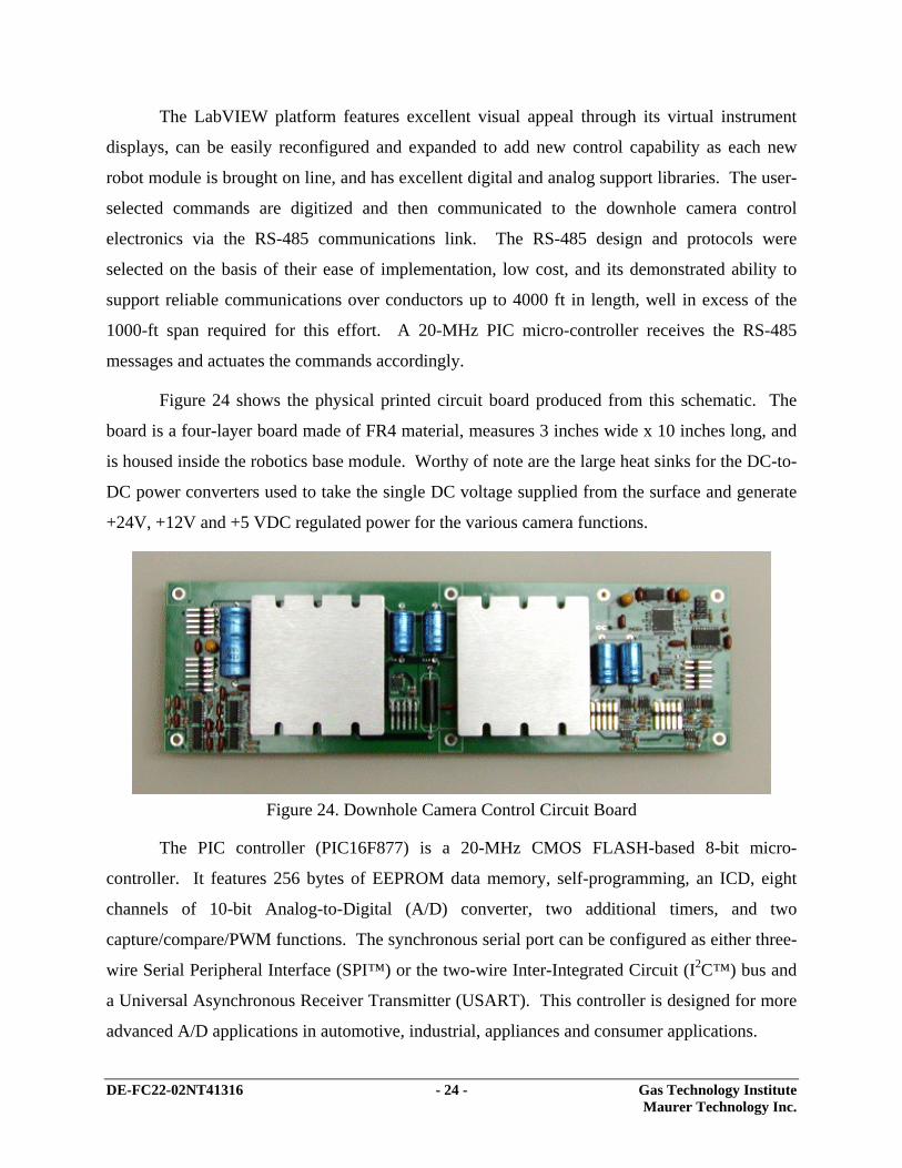
Figure 24 shows the physical printed circuit board produced from this schematic. The
board is a four-layer board made of FR4 material, measures 3 inches wide x 10 inches long, and
is housed inside the robotics base module. Worthy of note are the large heat sinks for the DC-to-
DC power converters used to take the single DC voltage supplied from the surface and generate
+24V, +12V and +5 VDC regulated power for the various camera functions.
Figure 24. Downhole Camera Control Circuit Board
The PIC controller (PIC16F877) is a 20-MHz CMOS FLASH-based 8-bit micro-
controller. It features 256 bytes of EEPROM data memory, self-programming, an ICD, eight
channels of 10-bit Analog-to-Digital (A/D) converter, two additional timers, and two
capture/compare/PWM functions. The synchronous serial port can be configured as either three-
wire Serial Peripheral Interface (SPI™) or the two-wire Inter-Integrated Circuit (I2C™) bus and
a Universal Asynchronous Receiver Transmitter (USART). This controller is designed for more
advanced A/D applications in automotive, industrial, appliances and consumer applications.
DE-FC22-02NT41316 - 25 - Gas Technology Institute Maurer Technology Inc.
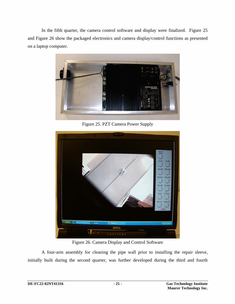
In the fifth quarter, the camera control software and display were finalized. Figure 25
and Figure 26 show the packaged electronics and camera display/control functions as presented
on a laptop computer.
Figure 25. PZT Camera Power Supply
Figure 26. Camera Display and Control Software
A four-arm assembly for cleaning the pipe wall prior to installing the repair sleeve,
initially built during the second quarter, was further developed during the third and fourth
DE-FC22-02NT41316 - 26 - Gas Technology Institute Maurer Technology Inc.
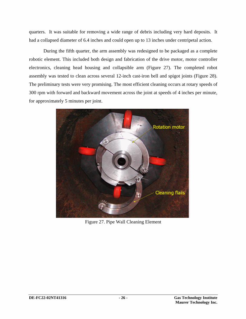
quarters. It was suitable for removing a wide range of debris including very hard deposits. It
had a collapsed diameter of 6.4 inches and could open up to 13 inches under centripetal action.
During the fifth quarter, the arm assembly was redesigned to be packaged as a complete
robotic element. This included both design and fabrication of the drive motor, motor controller
electronics, cleaning head housing and collapsible arm (Figure 27). The completed robot
assembly was tested to clean across several 12-inch cast-iron bell and spigot joints (Figure 28).
The preliminary tests were very promising. The most efficient cleaning occurs at rotary speeds of
300 rpm with forward and backward movement across the joint at speeds of 4 inches per minute,
for approximately 5 minutes per joint.
Figure 27. Pipe Wall Cleaning Element

DE-FC22-02NT41316 - 27 - Gas Technology Institute Maurer Technology Inc.
Figure 28. Pipe Wall Cleaning Test
During the tenth quarter, the small-diameter pipe repair robot was field tested for
inspecting and repairing 4-inch cast iron bell and spigot joints. Because much of the small
system’s design and performance closely tracks that used in the large diameter system described
herein, these field tests provide valuable experience and insight for design improvements for the
large-diameter cast iron pipe repair system.
Based on the field tests of the smaller system, several important recommendations were
developed. (These are summarized under “Lessons Learned/Recommendations for Large-
Diameter System” under Task 9 below.) The following recommendations regarding debris
collection and removal were suggested for the large-diameter system under development.
1. Cleaning flails were very effective. (No change is recommended for large system.)
2. Brush module should be added to move debris away from area surrounding the joint.
3. A magnetic coupon catcher should be added to remove existing coupons created by
service tee connections. In the large system, this catcher might mount to the camera
and employ the tilt function to capture the coupon.

DE-FC22-02NT41316 - 28 - Gas Technology Institute Maurer Technology Inc.
During the eleventh quarter, several designs were developed for improving debris
removal. Magnetic assemblies (Options 1 and 2 below) would be the most practical for removing
coupons and other large debris. Dirt is another challenge in low pressure mains that have been
invaded by ground water. Options 3 and 4 address concepts to sweep debris from the joint area.
In the large robotic system, these concepts for debris removal will most likely be applied in
combination to address all types of debris to be encountered in the main.
Option 1 (for Ferromagnetic Debris): Embed Magnets in Cleaning Arms
The first option for modifying the system to improve removal of ferromagnetic debris
consists of embedding magnets in the existing pipe cleaning arms (Figure 29). These magnets
would capture ferromagnetic debris as it is dislodged from the pipe wall. This design would not
require any additional tooling/attachments and would improve debris removal during the
cleaning run without requiring any changes to current operating procedures.
Swing Arm
CleaningRoller
EmbeddedMagnets
Figure 29. Embedded Magnets to Collect Debris
The disadvantage of this approach is a finite capacity for storing debris as it is collected.
If too much debris attaches to the swing arm, the swing arm may be prevented from returning to
the travel position (causing problems when removing the assembly from the main). Another
unknown is how much impact/shock the embedded magnets could withstand without becoming
dislodged or breaking. Due to the magnets’ limited storage capacity, it may be required that the
DE-FC22-02NT41316 - 29 - Gas Technology Institute Maurer Technology Inc.
cleaning assembly be retrieved after every few joints for removing debris from the magnets
before further in-pipe cleaning operations can resume.
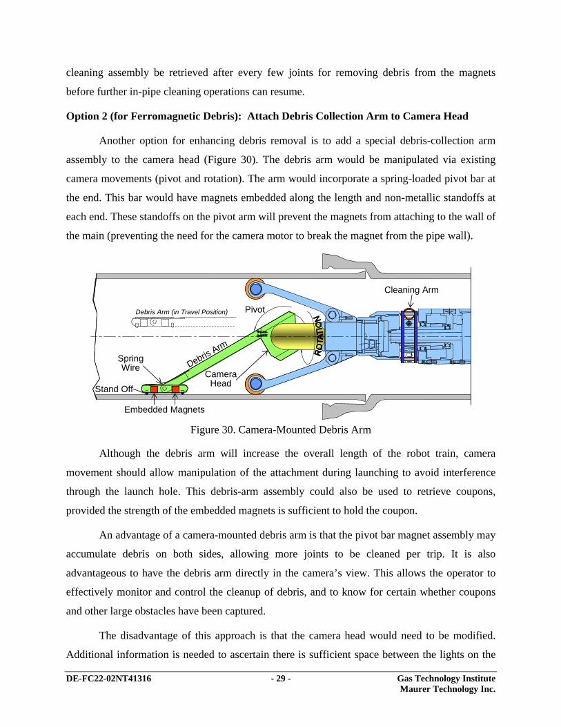
Option 2 (for Ferromagnetic Debris): Attach Debris Collection Arm to Camera Head
Another option for enhancing debris removal is to add a special debris-collection arm
assembly to the camera head (Figure 30). The debris arm would be manipulated via existing
camera movements (pivot and rotation). The arm would incorporate a spring-loaded pivot bar at
the end. This bar would have magnets embedded along the length and non-metallic standoffs at
each end. These standoffs on the pivot arm will prevent the magnets from attaching to the wall of
the main (preventing the need for the camera motor to break the magnet from the pipe wall).
Embedded Magnets
Stand Off
SpringWire
CameraHead
Pivot
Cleaning Arm
Debris Arm (in Travel Position)
Debris Arm
Figure 30. Camera-Mounted Debris Arm
Although the debris arm will increase the overall length of the robot train, camera
movement should allow manipulation of the attachment during launching to avoid interference
through the launch hole. This debris-arm assembly could also be used to retrieve coupons,
provided the strength of the embedded magnets is sufficient to hold the coupon.
An advantage of a camera-mounted debris arm is that the pivot bar magnet assembly may
accumulate debris on both sides, allowing more joints to be cleaned per trip. It is also
advantageous to have the debris arm directly in the camera’s view. This allows the operator to
effectively monitor and control the cleanup of debris, and to know for certain whether coupons
and other large obstacles have been captured.
The disadvantage of this approach is that the camera head would need to be modified.
Additional information is needed to ascertain there is sufficient space between the lights on the
DE-FC22-02NT41316 - 30 - Gas Technology Institute Maurer Technology Inc.
camera head to add mounting holes for the debris arm. Another potential disadvantage is that the
debris arm will be directly in front of the camera at all times and block part of the field of view.
However, since the camera can be rotated on its axis to view the entire ID of the main, this loss
of field can be compensated for.
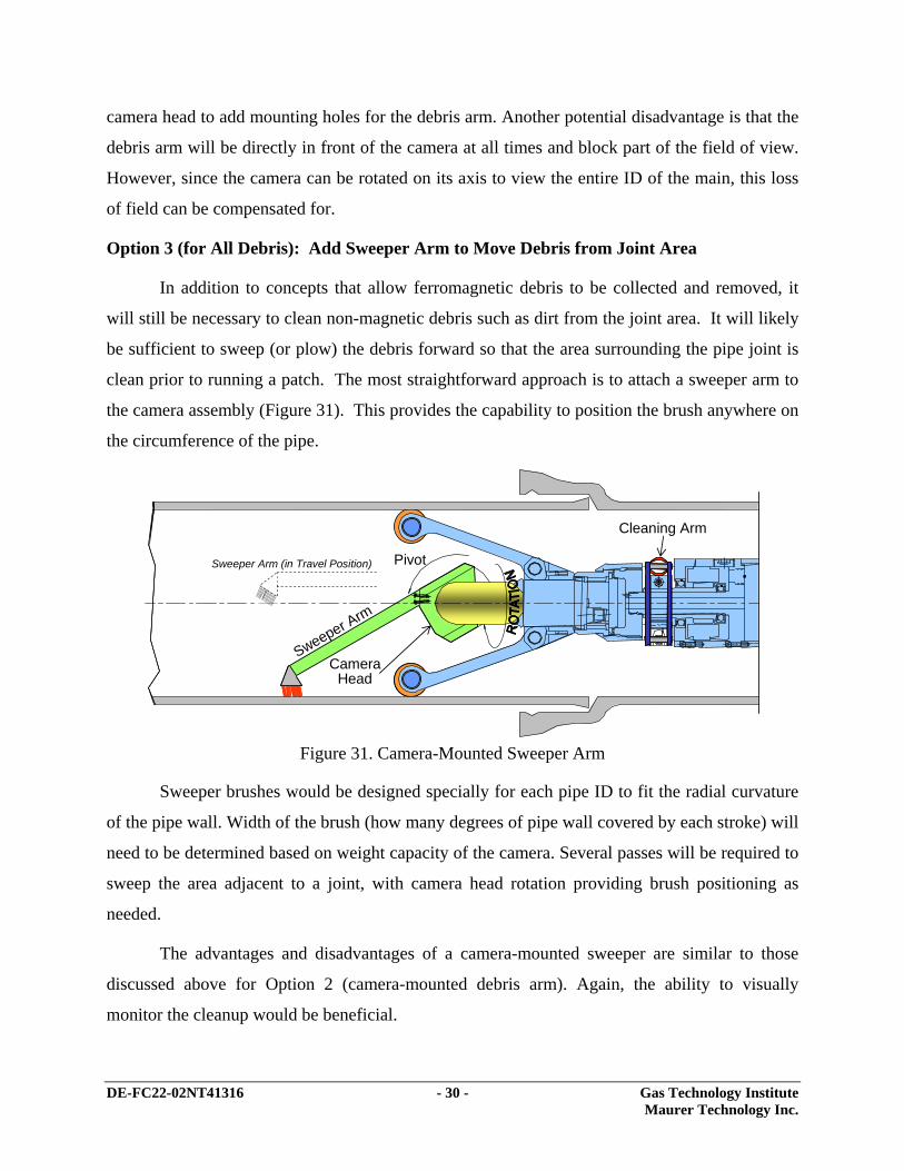
Option 3 (for All Debris): Add Sweeper Arm to Move Debris from Joint Area
In addition to concepts that allow ferromagnetic debris to be collected and removed, it
will still be necessary to clean non-magnetic debris such as dirt from the joint area. It will likely
be sufficient to sweep (or plow) the debris forward so that the area surrounding the pipe joint is
clean prior to running a patch. The most straightforward approach is to attach a sweeper arm to
the camera assembly (Figure 31). This provides the capability to position the brush anywhere on
the circumference of the pipe.
CameraHead
Pivot
Cleaning Arm
Sweeper Arm (in Travel Position)
Sweeper Arm
Figure 31. Camera-Mounted Sweeper Arm
Sweeper brushes would be designed specially for each pipe ID to fit the radial curvature
of the pipe wall. Width of the brush (how many degrees of pipe wall covered by each stroke) will
need to be determined based on weight capacity of the camera. Several passes will be required to
sweep the area adjacent to a joint, with camera head rotation providing brush positioning as
needed.
The advantages and disadvantages of a camera-mounted sweeper are similar to those
discussed above for Option 2 (camera-mounted debris arm). Again, the ability to visually
monitor the cleanup would be beneficial.

DE-FC22-02NT41316 - 31 - Gas Technology Institute Maurer Technology Inc.
Option 4 (for All Debris): Modify Cleaner Assembly to Sweep Debris Forward
Another concept would promote axial sweeping of the debris during the cleaning
operation (Figure 32). Here, the rotating cleaning arms would be redesigned with wire elements
instead of a serrated roller. Wire elements mounted at an angle (skewed) might promote debris
displacement axial away from the area being cleaned. This option would require the operator to
manipulate the robot train from the surface in the forward direction after the motor has
commenced rotation.
Wire CleanerElements
SwingArm Movement of Assembly
Cleaning Elements Skewed
Figure 32. Cleaning Elements Modified to Sweep Debris Forward
A disadvantage of this approach is that the debris is only moved slightly ahead of the
current joint. For best results and to avoid picking up debris with the patch as it is run in, each
joint would be cleaned, swept, and patched before moving to the next joint. Thus, this option
would require more trips and may be less desirable for that reason.
Task 6 – Design and Build Surface Control and Monitoring System
Surface control and monitoring electronics are being designed to operate inside the
LabVIEW platform operated on a high-end laptop computer. To this point, we have completed
the control software and visual display for the PZT camera and control software for operating the
pipe wall cleaning head. Work has continued onward with development of the control software
for setting the patch inside the pipe. Final packaging will be consistent with construction field-
ready practices.

DE-FC22-02NT41316 - 32 - Gas Technology Institute Maurer Technology Inc.
The deliverables for this task will be the Prototype Surface Control and Monitoring
System in addition to all corresponding electrical/electronic schematics, specifications, and parts
lists.
Task 7 – Design and Fabricate Large-Diameter Live Access System
Since the entry fitting system for cast-iron pipe cannot be welded directly onto the cast-
iron pipe body (as is possible with steel pipelines), some other means of attachment must be
used. One choice is to weld the longitudinal seams of the split entry fitting to itself and then to
provide an end seal against axial movement and a circumferential face seal by end bolting two
end pieces. The entry fitting will enable a port to be cut into the main for inserting all joint-
patching equipment. The entry fitting must provide sealing for conducting repair operations, as
well as maintain a safe seal over the life of the pipeline since the entry fitting will not be
removed from the main. Subtasks include:
7.1 Perform Stress Analysis. A certain portion of the main’s cross section will need
to be removed for access. The entry-fitting system must possess mechanical
properties that ensure that basic mechanical integrity of the main/joint is not
compromised. The design must take into account bending/flexure loading,
settling, reactive forces, and other environmental factors.
7.2 Design Seal that will be Maintained Under Loaded Conditions. The fitting and
seal design must be robust to accommodate any flexural loading conditions. Seals
must remain “energized” at all times during entry and inspection when the main is
exposed.
7.3 Perform Sealing Analysis. The appropriate material must be selected to meet
temperature, environmental, and lifetime requirements. An effective seal must be
maintained in the event of settling and varying ground conditions.
MTI and GTI previously met with a leading fitting manufacturer. Numerous designs were
subjected to an in-depth review with both the manufacturer and with several utilities who operate
significant lengths of large diameter cast-iron pipes. These efforts have produced a
recommended design satisfying the standards in-place at each of the utilities interviewed.
DE-FC22-02NT41316 - 33 - Gas Technology Institute Maurer Technology Inc.
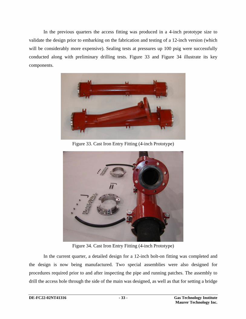
In the previous quarters the access fitting was produced in a 4-inch prototype size to
validate the design prior to embarking on the fabrication and testing of a 12-inch version (which
will be considerably more expensive). Sealing tests at pressures up 100 psig were successfully
conducted along with preliminary drilling tests. Figure 33 and Figure 34 illustrate its key
components.
Figure 33. Cast Iron Entry Fitting (4-inch Prototype)
Figure 34. Cast Iron Entry Fitting (4-inch Prototype)
In the current quarter, a detailed design for a 12-inch bolt-on fitting was completed and
the design is now being manufactured. Two special assemblies were also designed for
procedures required prior to and after inspecting the pipe and running patches. The assembly to
drill the access hole through the side of the main was designed, as well as that for setting a bridge
DE-FC22-02NT41316 - 34 - Gas Technology Institute Maurer Technology Inc.
plug within the fitting to allow removal of equipment and the gate valve prior to setting a blind
flange to permanently reseal the main. These assemblies are described in more detail below.
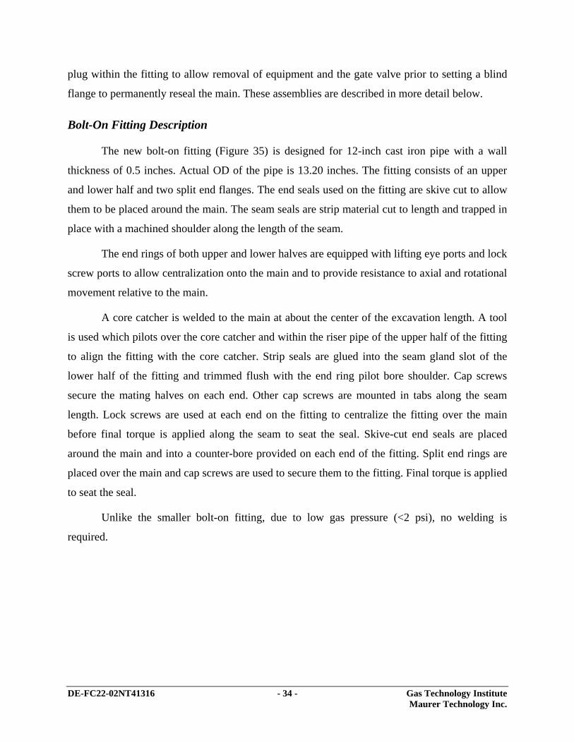
Bolt-On Fitting Description
The new bolt-on fitting (Figure 35) is designed for 12-inch cast iron pipe with a wall
thickness of 0.5 inches. Actual OD of the pipe is 13.20 inches. The fitting consists of an upper
and lower half and two split end flanges. The end seals used on the fitting are skive cut to allow
them to be placed around the main. The seam seals are strip material cut to length and trapped in
place with a machined shoulder along the length of the seam.
The end rings of both upper and lower halves are equipped with lifting eye ports and lock
screw ports to allow centralization onto the main and to provide resistance to axial and rotational
movement relative to the main.
A core catcher is welded to the main at about the center of the excavation length. A tool
is used which pilots over the core catcher and within the riser pipe of the upper half of the fitting
to align the fitting with the core catcher. Strip seals are glued into the seam gland slot of the
lower half of the fitting and trimmed flush with the end ring pilot bore shoulder. Cap screws
secure the mating halves on each end. Other cap screws are mounted in tabs along the seam
length. Lock screws are used at each end on the fitting to centralize the fitting over the main
before final torque is applied along the seam to seat the seal. Skive-cut end seals are placed
around the main and into a counter-bore provided on each end of the fitting. Split end rings are
placed over the main and cap screws are used to secure them to the fitting. Final torque is applied
to seat the seal.
Unlike the smaller bolt-on fitting, due to low gas pressure (<2 psi), no welding is
required.
DE-FC22-02NT41316 - 35 - Gas Technology Institute Maurer Technology Inc.
Figure 35. Bolt-On Fitting for Live Access into 12-in. Cast-Iron Mains
A ASe
ctio
n A
-A
Cla
mp
Bolt
Hol
es
Bol
t Tab
s
Stri
p G
aske
t
Lifti
ng E
ye P
ortC
ore
Cat
cher
Ris
er
Spl
it-En
d Fl
ange
Gas
Mai
n
Ski
ve-C
ut P
acki
ngLo
ck S
crew
Por
t

DE-FC22-02NT41316 - 36 - Gas Technology Institute Maurer Technology Inc.
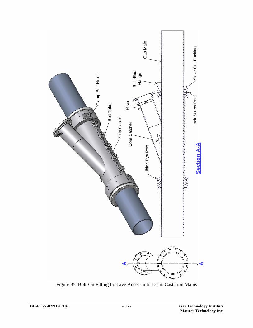
Drilling Assembly Description
After the bolt-on fitting is attached to the main and pressure tested, a control valve is
attached to the flange provided on the end of the riser. The valve is used to control gas flow as
the drilling assembly is removed after the entry hole is cut and as robot components are launched
and retrieved from the main. A cutter shroud is attached to the top of the control valve. The
shroud is used to house the cutter after the entry hole is cut and provides a gas seal until the
control valve is closed. This shroud remains attached after the drilling assembly is removed and
is used for launching and retrieving operations.
The drilling assembly (Figure 36) consists of a cutter attached to a drive shaft which is
attached to a drive motor. The motor is mounted to an adaptor which is threaded into the jack
screw translation shaft. A jack screw sleeve is mounted between the motor adaptor and the
translation shaft. As the jack screw sleeve is threaded into the shroud end cap, thrust force is
applied to the translation sleeve which forces the cutter toward the gas main. Rotational reaction
forces are carried through a hexagon drive provided on the extension portion of the jack screw
stationary shaft and the end of the bore of the translation shaft. The stationary shaft is locked to
the cutter shroud with a sealed lock pin which is removed when the cutter is retracted back into
the shroud after the entry hole is cut.
A cutter centralizer guides the cutter through the riser inside bore as it moves toward the
main. A wire spear mounted on the end of the drive shaft engages the core catcher as the cutter is
advanced. Once engaged and the entry hole is cut, the spear retains the coupon within the cutter
as the drilling assembly is retracted into the cutter shroud.
DE-FC22-02NT41316 - 37 - Gas Technology Institute Maurer Technology Inc.
Figure 36. Drilling Assembly for Cutting Access Hole in 12-in. Cast-Iron Mains
A ASe
ctio
n A
-A
Driv
e M
otor
Mot
or A
dapt
or
26.5
25.7
33.1
26.8
30.2
24.4
Jack
Sc
rew
Sle
eve
Hex
Loc
kEn
d C
apC
utte
r Shr
oud
Driv
e S
haft
Rot
ary
Seal
Cut
ter C
entra
lizer
Anti-
rota
tion
Seal
ed L
ock
Pin
Con
trol V
alve
(Slid
e G
ate)
7.84
” Cut
ter
DE-FC22-02NT41316 - 38 - Gas Technology Institute Maurer Technology Inc.
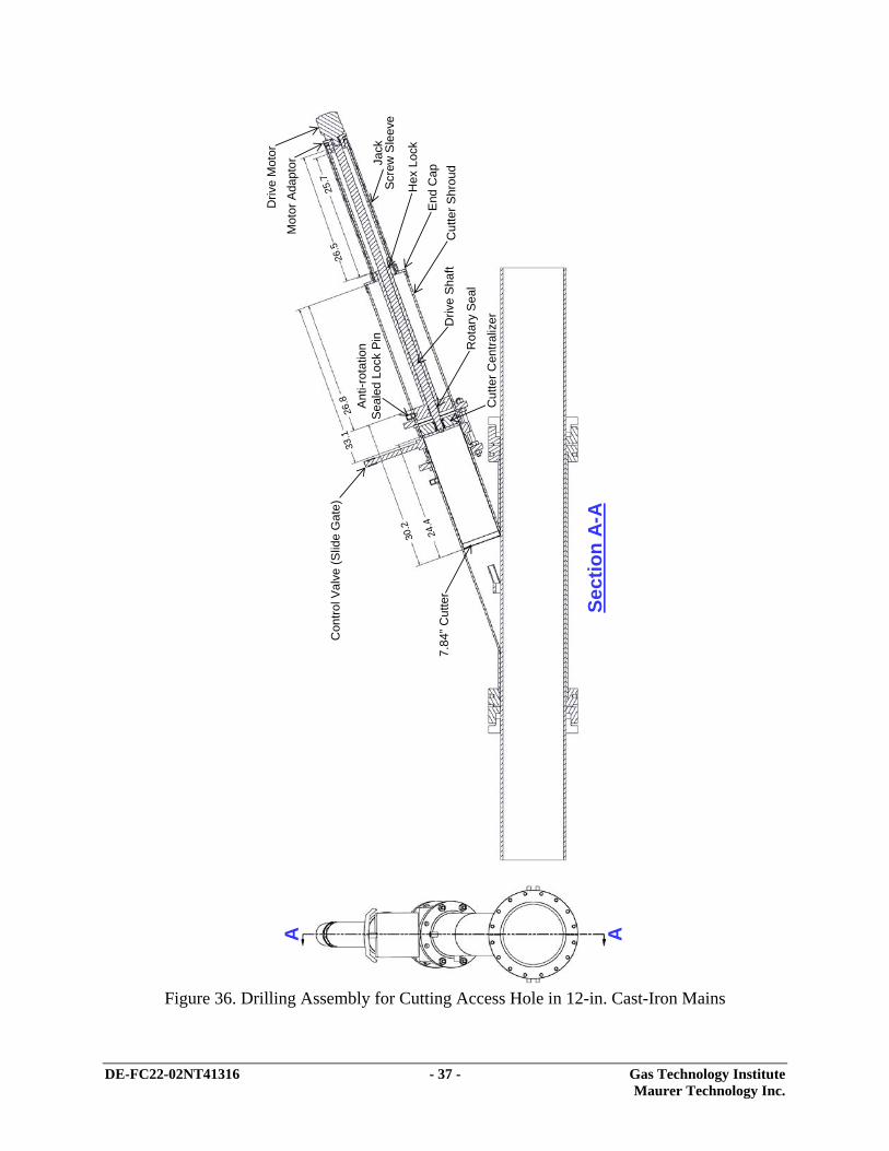
The project team sought to minimize the weight of each component. Several items are to
be manufactured from aluminum. In addition, a lightweight thermoplastic gate valve was
acquired for use with the assembly (Figure 37). This option reduces the valve weight and overall
drilling assembly length dramatically. Conventional ball valves for this size are about 18 inches
flange to flange and weigh about 400 lb. They are not manufactured commercially using
lightweight materials. The lightweight gate valve obtained is about 8 inches flange to flange and
weighs only 22 lb.
Figure 37. PVC Control Valve
A rotary shaft seal is provided to reduce the seal area and thus the forces produced by the
gas main internal pressure. Tooling (large wrench) is provided to allow the operator to
manipulate the jack screw sleeve by hand as to maintain operator feed back during drilling
operations.
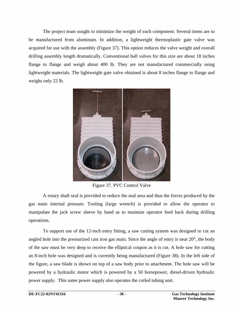
To support use of the 12-inch entry fitting, a saw cutting system was designed to cut an
angled hole into the pressurized cast iron gas main. Since the angle of entry is near 20°, the body
of the saw must be very deep to receive the elliptical coupon as it is cut. A hole saw for cutting
an 8-inch hole was designed and is currently being manufactured (Figure 38). In the left side of
the figure, a saw blade is shown on top of a saw body prior to attachment. The hole saw will be
powered by a hydraulic motor which is powered by a 50 horsepower, diesel-driven hydraulic
power supply. This same power supply also operates the coiled tubing unit.

DE-FC22-02NT41316 - 39 - Gas Technology Institute Maurer Technology Inc.
Figure 38. Hole Saw for Cutting Access Hole in Gas Main
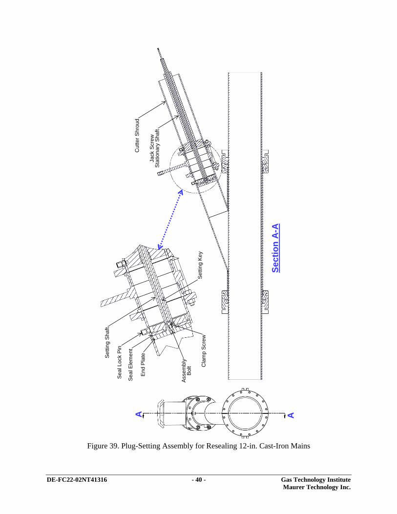
Plug-Setting Assembly Description
After patch-setting operations are complete, an expandable plug will be set into the fitting
to control gas flow as the control valve is removed from the bolt-on fitting. A special assembly
was designed for this procedure (Figure 39). A blind flange is placed on the riser flange to
complete the abandonment process. Because the expandable plug remains in place after the
fitting is sealed, the blind flange can later be removed to re-enter the main as necessary without
any flow of gas.
The expandable plug consists of an end plate, a body, a clamp screw and an assembly
screw. An elastomer element is placed between the end plate and body for sealing to the riser
inside diameter when compressed. The element is relaxed while lowering into the riser. The plug
assembly is attached to a setting shaft which is placed inside the jack screw stationary shaft.
Once in place a sealed lock pin is threaded through a side port provided on the riser. The lock pin
serves as an anti-rotation stop for the expandable plug body. A hex key is placed through the
setting shaft and engages the clamp screw. Rotating the clamp screw with the hex key causes the
end plate and the plug body to move together and compress the elastomer element. The element
expands until it contacts the wall. The setting shaft and setting key are removed from the plug by
retracting through the control valve and cutter shroud. After the shroud and control valve are
removed, a second lock pin may be installed through a second port provided on the riser of the
bolt-on fitting and a blind flange mounted to the riser flange.
DE-FC22-02NT41316 - 40 - Gas Technology Institute Maurer Technology Inc.
Figure 39. Plug-Setting Assembly for Resealing 12-in. Cast-Iron Mains
A A
Sect
ion
A-A
End
Plat
e
Seal
Ele
men
t
Seal
Loc
k Pi
n
Setti
ng S
haft
Setti
ng K
eyC
lam
p S
crew
Asse
mbl
y Bo
lt
Cut
ter S
hrou
d
Jack
Scr
ew
Stat
iona
ry S
haft

DE-FC22-02NT41316 - 41 - Gas Technology Institute Maurer Technology Inc.
Task 8 – System Integration and Laboratory Validation
While the previous tasks were aimed at addressing specific areas of the proposed work,
some aspects of performance will be difficult to assess until components are integrated. To
support the evaluation of system performance, a detailed Test Plan will be written. Many aspects
of the design cannot be accurately evaluated until an integrated test is performed. Some of these
items are listed below along with potential means of mitigating difficulties encountered. The test
plan will be written as the design progresses to ensure that all sensitive points will be examined
as part of an integrated test program.
8.1 The team will accumulate valuable experience with the equipment to assure
proficiency in the field, to verify that all elements work in concert, etc.
8.2 Actual push and pull loads will be measured, because these affect ultimate push
range of the integrated hardware assemblies and therefore the number of cast-iron
pipe joints which can be repaired from a single entry point
8.3 Measurement of actual end loads and reduction of these loads (if necessary) to
achieve targeted performance
8.4 Evaluation of “whip” (flexible) joint design for fatigue resistance and stiffness
under actual entry, translation and removal processes
The deliverable for this task will be the Integrated Test Plan. No activity occurred in this
task during the current quarter.
Task 9 – Field Testing and System Refinement
The first-generation system will be evaluated in a series of three field tests. These tests
will highlight improvements to “harden” the system for commercial viability. Iterative design
augmentations will be implemented and verified. Prior working relationships exist between the
project team and the following major U.S. gas utilities: KeySpan Energy (Brooklyn Union Gas
and Boston Gas), Consolidated Edison of New York, Public Service Electric & Gas of New
Jersey, and Baltimore Gas & Electric. These utilities operate the vast majority of large-diameter
cast-iron gas mains in the U.S. and are logical candidates for participating in field tests.

DE-FC22-02NT41316 - 42 - Gas Technology Institute Maurer Technology Inc.
During the tenth quarter, the small diameter pipe repair robot was field tested at Public
Service Electric & Gas. The field test consisted of the inspection and repair of 4-inch cast iron
bell and spigot joints. As much of this system’s design and performance closely tracks that used
in the large diameter system, these test results have a direct bearing on system design parameters.
As such, a summary of this field test is included below along with a list of design
recommendations to be implemented in the large diameter cast iron pipe repair system.
Summary of Field Tests of Small Robotic System
On August 24-26, 2004, MTI/GTI conducted field tests of the small robotic joint-repair
system in a gas main provided by Public Service Electric & Gas (Figure 40). The location was
in a residential neighborhood on Woodland Avenue in the town of Oradell, New Jersey.
Figure 40. Field Test Site
Over three days of field testing, a range of operations were performed representing a
typical joint-patching operation of bell and spigot joints on cast iron pipe. After the main was
uncovered and prepared for the tests, the coupon retention fitting was welded to the pipe. Next,
the 20° angled entry fitting was secured to the pipe (Figure 41) and then seam-welded to the
main.

DE-FC22-02NT41316 - 43 - Gas Technology Institute Maurer Technology Inc.
Figure 41. Attaching Entry Fitting to Pipe Prior to Welding
A hole saw assembly was then prepared for cutting through the wall of the main. The
access hole was successfully cut through the pipe and the hardware for admitting the repair
robots into the live gas main installed in a total time of 36 minutes.
The coupon was successfully retrieved. Next, a magnetic cleaning assembly (Figure 42)
was run into the pipe for three passes to remove the vast majority of metal filings created by the
sawing process.
Figure 42. Magnet Assembly for Removing Filings
The first train assembly consists of (1) a CCD camera to inspect the main, (2) a brush
module for cleaning the bell and spigot joints selected for repair, and (3) a base module which

DE-FC22-02NT41316 - 44 - Gas Technology Institute Maurer Technology Inc.
supplies electrical power, communication and control signals between the surface hardware and
the in-pipe robot elements. After the assembly was passed through the entry fitting (Figure 43),
the first run down the pipe was to inspect the environment and log the location of potential target
joints and other features.
Figure 43. Moving through Entry Fitting
Several locations at pipe joints were brushed (cleaned) to remove debris from the pipe.
Due to extremely low pressure and low gas velocity in the pipe, debris was not swept away from
the joint but tended to fall and accumulate across the joint.
Next, a total of six sleeve patches were run into the pipe. These included two successful
patches, two partially set patches, and two failed patches that were retrieved from the main. A
summary of patching operations is presented below.
• Two sleeves (at 128.8 ft and 93.7 ft) were run and set 100% successfully (Figure 44).

DE-FC22-02NT41316 - 45 - Gas Technology Institute Maurer Technology Inc.
Figure 44. Successfully Set Patch at 93.7 ft
• One sleeve (at 58.6 ft) failed in the first attempt to set it, was carried with the assembly
back to the entry point, and was then rerun and set successfully (although the ratchets did
not engage completely (Figure 45)).
Figure 45. Partially Engaged Patch at 58.6 ft
• One sleeve (at 6.1 ft) was partially set (ratchets did not engage properly).
• Two sleeves were run (to 42.0 ft and 24.1 ft) but were not able to engage the ratchets.
Potential causes for the failure of two patches to set are (1) pipe ID may have been
smaller than the first row of ratchets at these two bell and spigot locations, (2) the debris levels
may have been too high or 3) the bell and spigots were angularly misaligned. No problems were

DE-FC22-02NT41316 - 46 - Gas Technology Institute Maurer Technology Inc.
observed with the repair sleeve setting train either in the field or after its return to Houston.
Consequently, the team believes that the patch-setting failures were due to geometric issues.
After all in-pipe operations were complete, the equipment was removed from the pipe
and disassembled. A seal plug was then inserted into the 20° riser section of the entry fitting.
Once the seal plug is set, the gate valve was then removed from the main. A blind flange was
then attached to the 20° riser to create a second (redundant) gas seal and allow future re-entry
into the pipe is so desired. The sealed entry fitting ready for burial is shown in Figure 46.
Figure 46. Entry Fitting Ready for Burial
Lessons Learned/Recommendations for Large-Diameter System
Based on the field tests of the smaller robotic system in 4-in. cast-iron mains, several
valuable lessons were learned. The following recommendations are suggested for the large-
diameter system under development:
Entry Fitting
1. Develop a bolt-on version of the fitting
2. Coupon catcher design is finalized and successful.
3. Cuttings-removal magnet was very effective for small system and should be finalized
similarly for large-diameter system.
DE-FC22-02NT41316 - 47 - Gas Technology Institute Maurer Technology Inc.
4. Guide shoe design was very effective for small system, and should be finalized similarly
for large-diameter system.
Wall Cleaning
5. Cleaning flails were very effective. No change is recommended for large system.
6. Brush module should be added to move (plow) debris away from area surrounding joint.
7. A magnetic coupon catcher should be added to remove existing coupons created by
service tee connections. In the large system, this catcher might mount to the camera and
employ the tilt function to capture the coupon.
Patch Setting
8. Carry sufficient moles of gas with the patch assembly to support at least two patch-setting
procedures per run.
Task 10 – Benefits Analysis
Initial work on data collection for conducting benefits analysis was begun. (Note that the
majority of work in this task will be conducted after the completion of field tests and detailed
discussions with the utilities hosting the tests.) These discussions will address the end-to-end
process of implementing the proposed large-diameter cast-iron main repair system in a real-
world field environment. Only in this way can the true benefit of the new system be assessed.
All aspects of the job will be analyzed, particularly costs of labor (number of personnel and
time), traffic management, impact on future maintenance operations for the repaired main,
impact to customers, and acceptability of the repair technique. The deliverable of this task will
be a report detailing these benefits with a focus on cost and overall benefit to infrastructure
reliability using the proposed system.
Task 11 – Final Report
The project final report will document all aspects of design and operation of the system.
Final results of the project will be presented to the NETL COR in a meeting in Pittsburgh.
No activity occurred in this task during the current quarter.

DE-FC22-02NT41316 - 48 - Gas Technology Institute Maurer Technology Inc.
Work Planned for Next Period
Planned activities for the next quarter will encompass elements of Tasks 5–10. Specific
work items will include:
1. Continued testing of the pipe wall cleaning module in conjunction with the PZT
camera under increasingly more difficult and realistic conditions. These tests will
be conducted in the laboratory with larger in-pipe travel distances, introduction of
more debris, and full exercise of the control electronics and software.
2. Continued testing of the patch-setting module and its use in setting the latest
generation of 12-inch repair sleeves. Test results will be used to optimize design of
the patch assembly and the patch-setting robot train.
3. Fabrication and testing of 12-inch version of the cast-iron bolt-on entry fitting.
4. Fabrication and testing of the hole saw used to cut and angled access hole into
pressurized cast-iron pipes.
5. Continued implementation of software controls and system displays into the
LabVIEW user-interface/robotics-control environment.
6. Collection of additional information and data to conduct benefit analysis.
7. Prepare for field test demonstration tentatively scheduled for August 2005.

DE-FC22-02NT41316 - 49 - Gas Technology Institute Maurer Technology Inc.
4. Conclusions
Activities in this quarter focused on Tasks 4–8. Important accomplishments are described
in Section 3. For Task 4 (Design, Fabricate and Test Patch Setting Robotic Train), previous
problems encountered with bladder design and elastomeric material expansion in the large mains
were addressed. A new bladder based on a commercially available design was obtained and
tested with success. As a result of tests, minor improvements were highlighted to improve
sleeve/bladder expansion and are now being pursued. Task 7 (Design and Fabricate Large
Diameter Live Access System) progressed to completing the detailed design for a bolt-on entry
fitting for 12-inch diameter cast-iron pipe in the current quarter. Design concepts have previously
been tested in 4-in. prototype entry fittings. The drilling assembly for cutting an access hole
through the wall of the gas main was also designed, along with a plug assembly to allow
removing all tools from the live main and setting a blind flange on the entry fitting prior to
burial. These designs are described in detail in the report.
DE-FC22-02NT41316 - 50 - Gas Technology Institute Maurer Technology Inc.
5. References
(No references are cited in this Quarterly Report.)