Embed Size (px)
Citation preview
SEAKEEPING AND MANOEUVERING
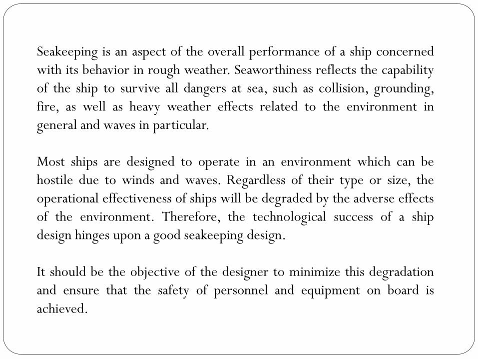
Seakeeping is an aspect of the overall performance of a ship concerned
with its behavior in rough weather. Seaworthiness reflects the capability
of the ship to survive all dangers at sea, such as collision, grounding,
fire, as well as heavy weather effects related to the environment in
general and waves in particular.
Most ships are designed to operate in an environment which can be
hostile due to winds and waves. Regardless of their type or size, the
operational effectiveness of ships will be degraded by the adverse effects
of the environment. Therefore, the technological success of a ship
design hinges upon a good seakeeping design.
It should be the objective of the designer to minimize this degradation
and ensure that the safety of personnel and equipment on board is
achieved.
Consequently, in today's competitive environment it is becoming
increasingly important for ship designers to demonstrate that their
proposed design has good seakeeping performance characteristics.
Today, it is widely accepted that seakeeping is a consideration that can
affect the final decision because it can affect the system’s cost (or profit)
through voluntary/involuntary speed reduction.
The way the various vessels meet and respond to those waves depends
strongly on their dimensions. The sea that is giving large motions to a
small tug boat or fishing vessel may go all but unnoticed by a passing
supertanker. Conversely, the structure of a Supertanker may be stressed
by a swell that, while awesome to view, may have little effect on the
operations of the smaller vessels.
In general the operability is increased by larger principal dimensions.
Obviously economic considerations impose limitations on the principal
dimensions, particularly length.
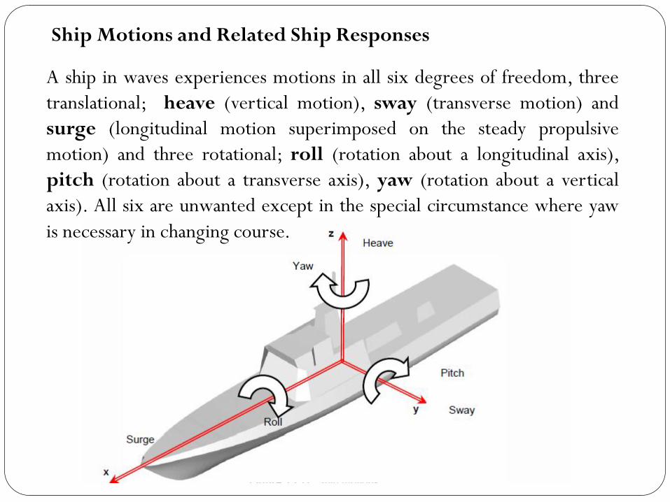
A ship in waves experiences motions in all six degrees of freedom, three
translational; heave (vertical motion), sway (transverse motion) and
surge (longitudinal motion superimposed on the steady propulsive
motion) and three rotational; roll (rotation about a longitudinal axis),
pitch (rotation about a transverse axis), yaw (rotation about a vertical
axis). All six are unwanted except in the special circumstance where yaw
is necessary in changing course.
Ship Motions and Related Ship Responses
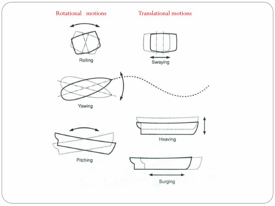
Rotational motions Translational motions
Heave, pitch and roll require particular mention because they are the
three motions with hydrostatic restoring forces (and moments), and
therefore possess natural response periods and the potential for
resonant behaviour. Heave tends, in almost all cases, to be well
damped, so resonant heave is usually not a problem. However, for a
surface effect ship (SES) natural heave oscillations can be excited due
to high encounter frequency between the vessel and waves. The
compressed air in the cushion causes heave resonance. Heave motion
is also important for offshore drilling vessels. Pitch likewise is usually
well damped. Pitch damping is maximized by full waterplane
development in the ends (high CWP) and relatively high beam-to-
draught ratios overall. Pitch motion is one of the main concerns in
head and bow seas. A strong pitch motion is usually followed by deck
wetness or bow slamming which are generally of greater importance.
Heave, Pitch and Roll
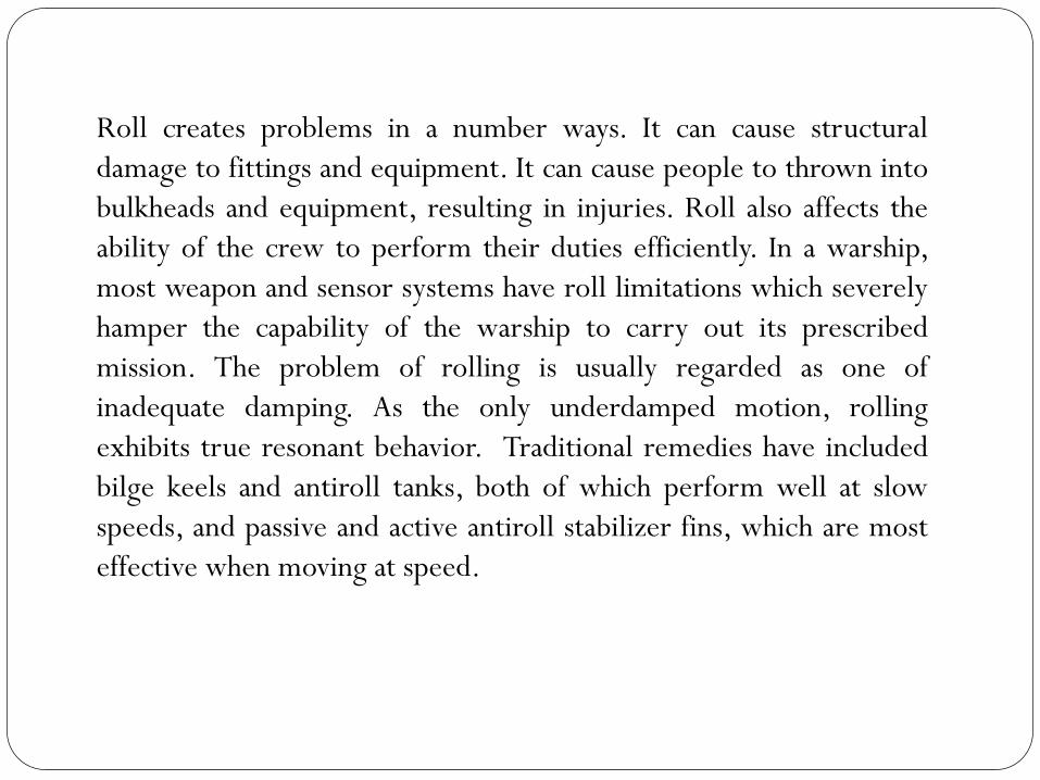
Roll creates problems in a number ways. It can cause structural
damage to fittings and equipment. It can cause people to thrown into
bulkheads and equipment, resulting in injuries. Roll also affects the
ability of the crew to perform their duties efficiently. In a warship,
most weapon and sensor systems have roll limitations which severely
hamper the capability of the warship to carry out its prescribed
mission. The problem of rolling is usually regarded as one of
inadequate damping. As the only underdamped motion, rolling
exhibits true resonant behavior. Traditional remedies have included
bilge keels and antiroll tanks, both of which perform well at slow
speeds, and passive and active antiroll stabilizer fins, which are most
effective when moving at speed.
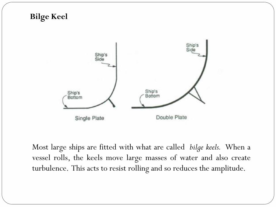
Most large ships are fitted with what are called bilge keels. When a
vessel rolls, the keels move large masses of water and also create
turbulence. This acts to resist rolling and so reduces the amplitude.
Bilge Keel
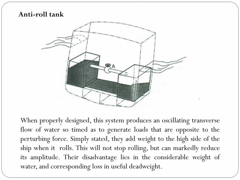
When properly designed, this system produces an oscillating transverse
flow of water so timed as to generate loads that are opposite to the
perturbing force. Simply stated, they add weight to the high side of the
ship when it rolls. This will not stop rolling, but can markedly reduce
its amplitude. Their disadvantage lies in the considerable weight of
water, and corresponding loss in useful deadweight.
Anti-roll tank
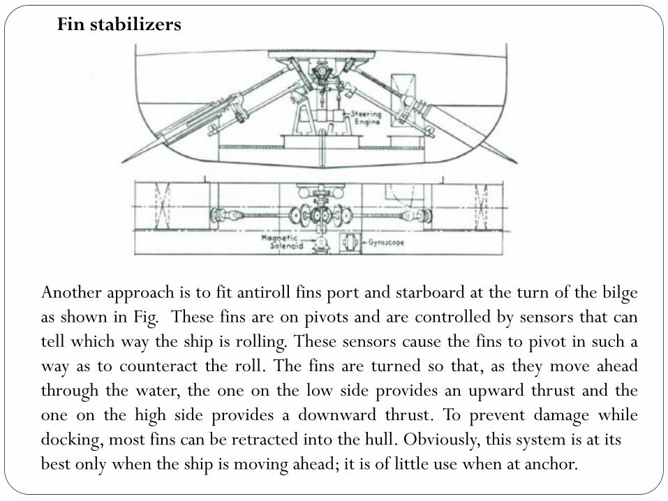
Another approach is to fit antiroll fins port and starboard at the turn of the bilge
as shown in Fig. These fins are on pivots and are controlled by sensors that can
tell which way the ship is rolling. These sensors cause the fins to pivot in such a
way as to counteract the roll. The fins are turned so that, as they move ahead
through the water, the one on the low side provides an upward thrust and the
one on the high side provides a downward thrust. To prevent damage while
docking, most fins can be retracted into the hull. Obviously, this system is at its
best only when the ship is moving ahead; it is of little use when at anchor.
Fin stabilizers
A boat's period of roll is directly proportional to its radius of gyration,
which is a measure of the boat's distribution of mass about its axis of
rotation. The greater the radius, the greater the resistance to change
in rotational motion. In practical terms this means that you can slow
your boat's rolling period by moving weights symmetrically
outboard, away from the center line.
A key factor affecting the ability of crew to properly function is the
level of vertical accelerations to which they are subjected. Also the
passenger comfort is closely related to the vertical acceleration
levels. It is known that vertical accelerations together with roll
motion are the main cause of seasickness.
Transverse accelerations on the ship, combined with sway and roll
motions can cause a shift of cargoes like ore or grain. Sea-fastenings
of containers at deck can collapse by too large accelerations and
vulnerable cargoes like fruits can be damaged.
Vertical and Transverse Accelerations
Deck Wetness
Deck wetness is defined as occurring when the bow of a vessel
plunges into a wave and the water rises above the edge of the deck at
the bow and washes aboard. Deck wetness is an important
seakeeping phenomenon, which frequently causes voluntary
reductions in ship speed, and threatens ship stability and structural
integrity. In extreme conditions, the frequent shipping of water may
lead to the capsize of the vessel; in more moderate conditions the loss
of the vessel is unlikely, but frequent deck wetness may still cause
damage to exposed fittings and deck cargo and make the upper deck
untendable for the crew.
When the forefoot of the ship emerges, an impact can occur at the
instant of re-entry. At certain level of intensity the hydrodynamic
impact of the forebottom can be noticed by the crew as a bang and a
deceleration in the foreship, followed by a shudder through the hull
girder. Slamming under the forebody has long been recognized as
imposing a limit on the performance of many classes of ships. Cases
are reported of ships experiencing bow structural damage due to
severe bottom slamming. Moreover, the psychological effect on a ship
operator of severe slamming is such as to demand a reduction of
speed or a change of course and this subjective reaction will differ
from individual to individual.
Slamming
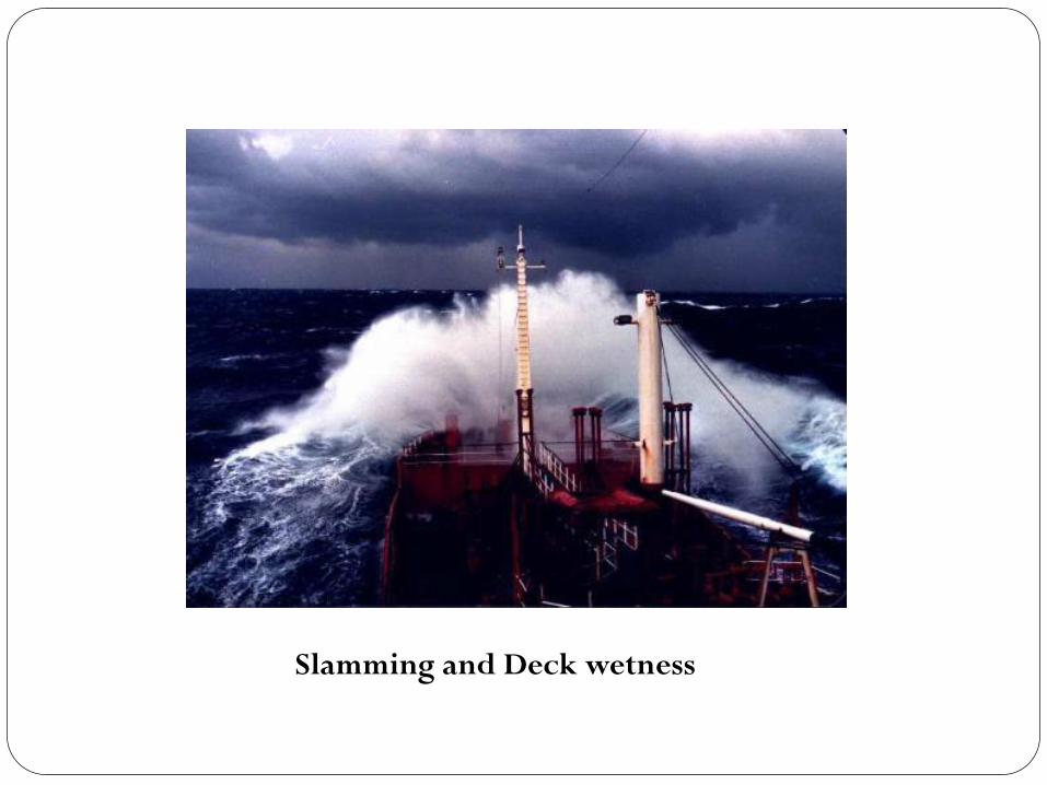
Slamming and Deck wetness
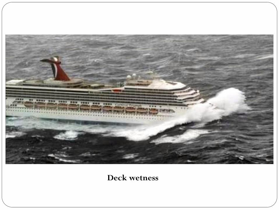
Deck wetness
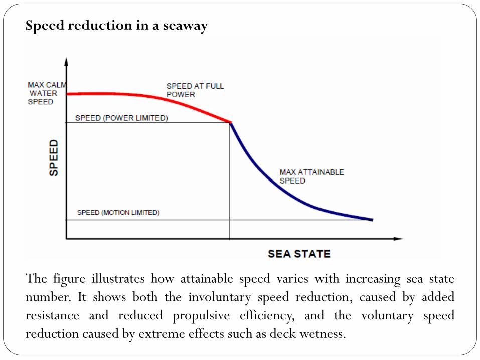
The figure illustrates how attainable speed varies with increasing sea state
number. It shows both the involuntary speed reduction, caused by added
resistance and reduced propulsive efficiency, and the voluntary speed
reduction caused by extreme effects such as deck wetness.
Speed reduction in a seaway
Manoeuvering Performance
All ships must be able to control their speed and follow an intended
course when in transit. Additionally, when entering congested waterways
or harbours, they must be able to position themselves accurately. To
achieve this, ships must have the means of producing ahead and astern
thrust, turning moments and lateral thrust. The last two are provided by
rudders of various types assisted, in some cases; by lateral thrust units at
the bow and/or stern. Ahead and astern thrust is usually provided by the
main propulsion system. Because rudders are usually sited close to the
propulsors there will exist an interaction between the two. Where more
than one shaft is fitted, a turning moment can be produced by going
ahead on one shaft and astern on the other.
The IMO Standards for ship manoeuvrability identify significant
qualities for the evaluation of ship manoeuvring characteristics:
Inherent dynamic stability: A ship is dynamically stable on a straight
course if it, after a small disturbance, soon will settle on a new
straight course without any corrective rudder. The resultant deviation
from the original heading will depend on the degree of inherent
stability and on the magnitude and duration of the disturbance.
Course-keeping ability: The course-keeping quality is a measure of the
ability of the steered ship to maintain a straight path in a
predetermined course direction without excessive oscillations of
rudder or heading. In most cases, reasonable course control is still
possible where there exists an inherent dynamic instability of limited
magnitude.
Initial turning/course-changing ability: The initial turning ability is
defined by the change-of-heading response to a moderate helm, in
terms of heading deviation per unit distance sailed (the P number) or
in terms of the distance covered before realizing a certain heading
deviation (such as the "time to second execute" demonstrated when
entering the zig-zag manoeuvre).
Yaw checking ability: The yaw checking ability of the ship is a measure
of the response to counter-rudder applied in a certain state of
turning, such as the heading overshoot reached before the yawing
tendency has been cancelled by the counter-rudder in a standard zig-
zag manoeuvre.
Turning ability: Turning ability is the measure of the ability to turn
the ship using hard-over rudder. The result being a minimum
"advance at 90° change of heading" and "tactical diameter"
defined by the "transfer at 180° change of heading". Analysis of
the final turning diameter is of additional interest.
Stopping ability: Stopping ability is measured by the "track reach"
and "time to dead in water" realized in a stop engine-full astern
manoeuvre performed after a steady approach at full test speed.
Lateral deviations are also of interest, but they are very sensitive to
initial conditions and wind disturbances.
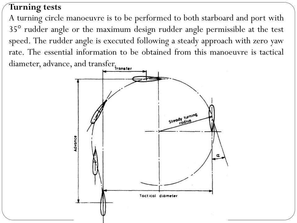
A turning circle manoeuvre is to be performed to both starboard and port with
35° rudder angle or the maximum design rudder angle permissible at the test
speed. The rudder angle is executed following a steady approach with zero yaw
rate. The essential information to be obtained from this manoeuvre is tactical
diameter, advance, and transfer.
Turning tests
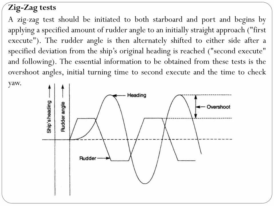
A zig-zag test should be initiated to both starboard and port and begins by
applying a specified amount of rudder angle to an initially straight approach ("first
execute"). The rudder angle is then alternately shifted to either side after a
specified deviation from the ship’s original heading is reached ("second execute"
and following). The essential information to be obtained from these tests is the
overshoot angles, initial turning time to second execute and the time to check
yaw.
Zig-Zag tests

This is a manoeuvre aimed at giving a feel for a ship's directional stability. From an initial
straight course and steady speed the rudder is put over say 15° to starboard. After a while the
ship settles to a steady rate of turn and this is noted. The rudder angle is then reduced to 10°
starboard and the new steady turn rate noted. This is repeated for angles of 5°S, 5°P, 10°P, 15T,
10T and so on. The resulting steady rates of turn are plotted against rudder angle.
The Spiral Manoeuvre
If the ship is stable there will be a unique rate of turn for each rudder angle. If the ship is unstable the plot
has two 'arms' for the smaller rudder angles, depending upon whether the rudder angle is approached from
above or below the value.
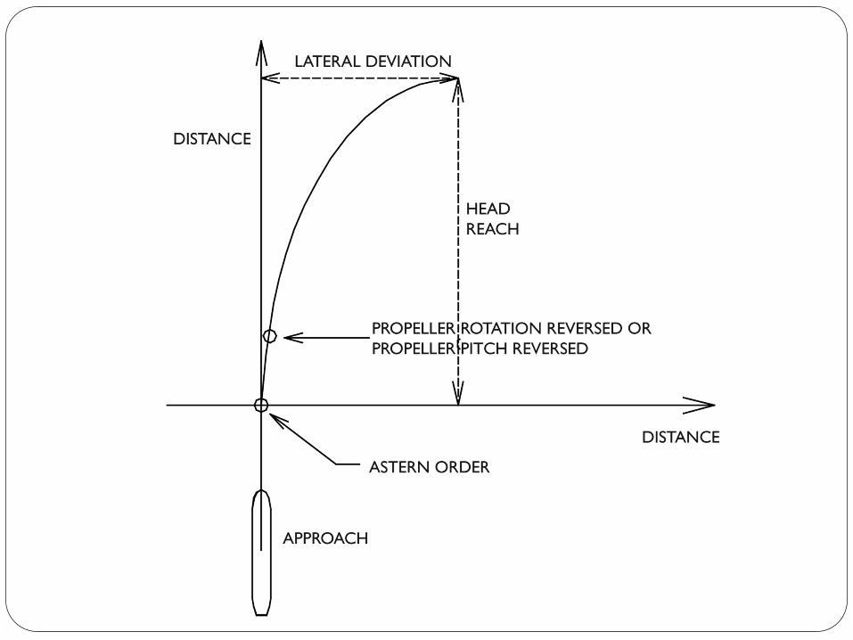
A full astern stopping test is used to determine the track reach of a ship
from the time an order for full astern is given until the ship is stopped
dead in the water. The "crash-stop" or "crash-astern" manoeuvre is mainly
a test of engine functioning and propeller reversal. The stopping distance
is essentially a function of the ratio of astern power to ship displacement.
A test for the stopping distance from full speed has been included in the
Standards in order to allow a comparison with hard-over turning results in
terms of initial speed drop and lateral deviations.
Stopping Tests
Modifying the Manoeuvering Performance
The effect of design changes on a ship's manoeuvring qualities can be expected that:
(1) Stern trim improves directional stability and increases turning diameter.
(2) A larger rudder can improve directional stability and give better turning.
(3) Decrease in draught can increase turning rate and improve directional stability. This
is perhaps due to the rudder becoming more dominant relative to the immersed hull.
(4) Higher length to beam ratios lead to a more stable ship and greater directional
stability.
(5) Quite marked changes in metacentric height, whilst affecting the heel during a turn,
have litde effect on turning rate or directional stability.
(6) For surface ships at a given rudder angle the turning circle increases in diameter with
increasing speed but rate of turn can increase. For submarines turning diameters are
little affected by speed.
(7) A large skeg aft will increase directional stability and turning circle diameter.
(8) Cutting away the below water profile forward can increase directional stability.
By and large the hull design of both a surface ship and a submarine is dictated by
considerations other than manoeuvring. If model tests show a need to change the
manoeuvring performance this would normally be achieved by modifying the areas and
positions of the control surfaces and skegs