Embed Size (px)
Citation preview

SE95004 Rev. 8
Operators ManualInstallation, Operation & Service
Electric Table Top Kettles
MODELS:Single Kettles
KET-3-T
KET-6-T
KET-12-T
KET-20-T*
Twin KettlesTKET-3-T
TKET-6-T
TKET-12-T
*Floor Type Leg Mount
1333 East 179th St., Cleveland, Ohio, U.S.A. 44110
Phone: (216) 481-4900 Fax: (216) 481-3782Visit our web site at www.clevelandrange.com
Cleveland™
Enodis

Shut off power at main fuse disconnect prior to servicing.
Ensure kettle is at room temperature and pressure gauge is showing zero or less prior to removing any fittings.
Inspect unit daily for proper operation.
0
Do not fill kettle above recommended level marked on outside of kettle.
Surfaces may be extremely hot! Use protective equipment.
Keep appliance and area free and clear of combustibles.
Stand clear of product discharge path when discharging hot product.
Wear protective equipment when discharging hot product.
Do not lean on or place objects on kettle lip.
Do not attempt to operate this appliance during a power failure.
Keep clear of pressure relief discharge.
Keep hands away from moving parts and pinch points.
SERVICING
IMPORTANT
CAUTION
DANGER
GAS APPLIANCES
For your safety

GENERAL Installation of the kettle must be accomplished byqualified electrical installation personnel workingto all applicable local and national codes.Improper installation of product could cause injuryor damage.
This equipment is built to comply with applicablestandards for manufacturers. Included amongthose approval agencies are: UL, NSF, ASME/Ntl.Bd., CSA, CGA, ETL, and others. Many localcodes exist, and it is the responsibility of theowner/installer to comply with these codes.
Note: Maximum voltage for LVD (low voltdirective for Europe) to be 440 volts for CEmarked appliances.
INSPECTIONBefore unpacking visually inspect the unit forevidence of damage during shipping.
If damage is noticed, do not unpack the unit, followShipping Damage Instructions shown below.
SHIPPING DAMAGE INSTRUCTIONSIf shipping damage to the unit is discovered orsuspected, observe the following guidelines inpreparing a shipping damage claim.
1. Write down a description of the damage or thereason for suspecting damage as soon as it isdiscovered. This will help in filling out the claimforms later.
2. As soon as damage is discovered orsuspected, notify the carrier that delivered theshipment.
3. Arrange for the carrier's representative toexamine the damage.
4. Fill out all carrier claims forms and have theexamining carrier sign and date each form.
INSTALLATIONThe first installation step is to refer to theSpecification Sheets or Specification Drawings fordetailed clearance requirements of the kettle.Next, carefully cut open the shipping carton foreasy removal of the kettle.
CLEARANCE REQUIREMENTS
* From back of mounting base.
POUR PATH
Kettle Size Min. Max.
3 Gallon 15 1/2” 32”
6 Gallon 17 1/4” 36”
12 Gallon 18” 38”
20 Gallon 22” 45”
Model # Back* Left Side Right Side
KET-3-T 2 1/4” 0 0
KET-6-T 2 3/4” 0 0
KET-12-T 5 1/2” 0 0
KET-20-T 8” 0 0
TKET-3-T 6 5/8” 0 0
TKET-6-T 7 1/8” 0 0
TKET-12-T 9 7/8” 0 0
INSTALLATION
Min.
Max.

ASSEMBLYTable-Top Models (3, 6 & 12 gallon)
Base Mounting Diagram
Table-top models (3, 6 & 12 gallon - single and twin)must be positioned on a firm, level stand, or existingcounter top, and bolted in place. These models aresupplied with four threaded mounting bushingswelded to the underside of the base. An optionalsupport stand with level adjustable legs is available.Once the kettle is secure, screw tilt handle into thethreaded hole provided at the right side of kettle.
Floor Type Leg Mount Models (20 gallon)
Base Mounting Diagram
Position on a firm, level surface, and bolt twoflange feet in place. Once the kettle is secure,screw tilt handle into the threaded hole providedat the right of kettle.
ELECTRICALENSURE THE ELECTRICAL SUPPLY MATCHESTHE KETTLE'S REQUIREMENTS AS STATEDON THE RATING LABEL.This kettle is built to comply with applicablestandards of manufacturers. Included amongthese approval agencies are UL, NSF, ASME/Ntl.Bd., CSA, ETL, and others. Many local codesexist, and it is the responsibility of the owner andinstaller to comply with these codes.
The electrical supply must match the powerrequirements specified on the kettle’s rating plate.The copper wiring must be adequate to carry therequired current at the rated voltage.
Note: Maximum voltage for LVD (low voltdirective for Europe) to be 440 volts for CEmarked appliances.
WIRE CONNECTIONIf unit does not have cord and plug option, removethe four screws securing the console cover andremove the cover. A wiring diagram is affixed tothe underside of the cover. Feed permanentcopper wiring through the cut-out in the rear orbottom of the console, and fasten to the threeconnection terminal block, which is mounted onthe top of the console’s control panel. Be sure toconnect the ground wire to the separate groundterminal connector (ground lug). Replace consolecover and secure it with the four screws.
The kettle is wired for 3-phase operation at thefactory. For single phase operation, rewire theterminal block to that shown in the above diagram.
WATER
14.5" 1.25"
12.5"
12.5"
18"
10"
10"
1.25"
1.25"
1.25 "
1.25"
A
B C1.25 "
KET-3-TKET-6-T
KET-12-T
TKET-3-TTKET-6-T
TKET-12-T
REDYELLOWBLACK
BLA
CK
BLU
E
RE
D
L1 L2 L3
THREEPHASE
REDYELLOWBLACK
BLA
CK
BLU
E
RE
D
L1 L2
SINGLEPHASE
Model # A B C
TKET-3-T 18" 2.25" 1.25"
TKET-6-T 24" 4.63" 4.63"
TKET-12-T 30" 7.75" 7.75"
28.5" 2.25"
14.5"
32"
12"
1.25"
1.25"
1.25"
KET-20-T
5/16" - 18 threaded bushings

The sealed jacket of the electric kettle isprecharged with the correct amount of a waterbased formula, and therefore, no water connectionis required to the kettle jacket. The kettle can beequipped with optional hot and/or cold waterfaucet, requiring 1/2" copper tubing as supplylines.
INSTALLATION CHECKSAlthough the kettle has been thoroughly testedbefore leaving the factory, the installer is responsiblefor ensuring the proper operation of kettle onceinstalled.
Visual Checks
1. Check Marine Lock. See Marine Lock TestingProcedure.
2. Check Tilting:
A/ Handle is in place and firmly tightened.
B/ Kettle tilts smoothly and freely.
3. Insure there are:
A/ Four screws securely holding the consolecover.
B/ The bottom cover is in place and held with anut.
Performance Checks
1. Supply power to the kettle by placing the fuseddisconnect switch to the "ON" position.
2. Before turning the kettle on, read the
Vacuum/Pressure Gauge (2). The gauge'sneedle should be in the green zone. If theneedle is in the "VENT AIR" zone, follow KettleVenting Instructions.
3. Turn the kettle's ON/OFF Switch/Solid StateTemperature Control (5) to "1" (Min.). The HeatIndicator Light (Green) (6) should remain lit,indicating the element is on, until the settemperature is reached (130°F/54°C). Then thegreen light will cycle on and off, indicating theelement is cycling on and off to maintaintemperature.
4. Tilt the kettle forward. After a few seconds theLow Water Indicator Light (Red) (4) should be litwhen the kettle is in a tilted position. This lightindicates that the element has automaticallybeen shut off by the kettle's safety circuit. This isa normal condition when the kettle is in a tiltedposition.
5. Raise the kettle to the upright position. The LowWater Indicator Light (Red) (4) should go outwhen the kettle is upright.
6. Turn the ON/OFF Switch/Solid State TemperatureControl (5) to "10" (Max.) and allow the kettle topreheat. The green light should remain on untilthe set temperature (260°F/127°C) is reached.Then the green light will cycle ON and OFF,indicating the element is cycling ON and OFF tomaintain temperature. Fill the kettle with coldwater to the steam jacket’s welded seam. Referto the Temperature Range Chart for the timerequired to bring the water to a boil.
7. When all testing is complete, empty the kettleand turn the ON/OFF Switch/Solid StateTemperature Control (5) to the “OFF” position.
CLEANINGAfter installation the kettle must be thoroughlycleaned and sanitized prior to cooking. SeeCleaning Instructions.
50
0
100150 200
250
300
350
400
40
50
60
0
10
20 30
psi kPa
VEN
TAI
R
MARINE LOCK
Your unit is equipped with amarine lock to preventaccidental tilting. The followingprocedure should be used to tiltthe kettle.
1. Grasp the tilt handle.
2. Hold the latch down to unlock tilting mechanism.
3. Pull the handle to tilt kettle.
4. To lock, return the kettle to its upright positionand push handle back.
NOTE: Inspect lock daily to ensure it is free
moving and does not bind or stick. Clean lock
if necessary (see Cleaning Instructions for
details).
LATCH

6
5
4
3
2
1
7
OPERATING INSTRUCTIONS
General Parts Drawing
ITEM # DESCRIPTION FUNCTION
1. Tilting Handle Used for tilting the kettle.
2. Vacuum/Pressure Gauge Indicate steam pressure in PSI inside steam jacket as well asvacuum in inches of mercury.
3. Pressure Relief Valve This valve is used to vent the kettle and in the unlikely event there is (not shown) an excess steam build-up in the jacket, this valve opens
automatically to relieve this pressure.
4. Low Water Indicator Light (Red) When lit, it indicates that the kettle is low on water and will not operate in this condition. This will also light when the kettle is tilted.
5. On-Off Switch/ Turns kettle ON/OFF and allows the operator to adjust the kettle Solid State Temperature temperature in increments from 1 (Min.) to 10 (Max.).Control (see Temperature Range Chart).
6. Heat Indicator Light (Green) When lit, indicates that the kettle's element is on. Cycles ON-OFF with element.
7. Marine Lock Prevents unit from accidental tilting.

OPERATING THE KETTLEDO NOT LEAN ON OR PLACE OBJECTS ONKETTLE LIP. SERIOUS INJURY COULD RESULTIF KETTLE TIPPED OVER, SPILLING HOTCONTENTS.
1. Before turning kettle on, read theVacuum/Pressure Gauge (2). The gaugesneedle should be in the green zone. Onceheated, the kettle's normal maximumoperating pressure is approximately 10-12 psi,while cooking a water base product.
2. Ensure that the electrical service to the kettleis turned on at the fused disconnect switch.
Temperature Range Chart
3. Preheat the kettle by turning the ON/OFFSwitch/Solid State Temperature Control (5) tothe desired temperature setting (see above"Temperature Range Chart"). The HeatIndicator Light (Green) (6) will remain lit,indicating the element is on, until thetemperature setting is reached. When thegreen light goes off, the elements are off, andpreheating is complete.
NOTE: When cooking egg and milk products, thekettle should not be preheated, as products of thisnature adhere to hot cooking surfaces. These types offood should be placed in the kettle before heating isbegun.
4. Place food product into the kettle. The HeatIndicator Light (Green) (6) will cycle on andoff indicating the elements are cycling on andoff to maintain the set temperature.
NOTE: Do not fill kettle aboverecommended level marked onoutside of kettle.
NOTE: The Low Water Indicator Light (Red) (4)should not be lit when kettle is in upright positionduring operation. This light indicates that theelements have been automatically shut off by thekettle's safety circuit. It is, however, normal for thered light to come on when the kettle is in a tiltedposition.
5. When cooking is completed turn ON/OFFSwitch/Solid State Temperature Control (5) tothe "OFF' position.
6. Pour the contents of the kettle into anappropriate container by tilting the kettleforward. Care should be taken to pour slowlyenough to avoid splashing off the product.
NOTE: As with cleaning food soil from anycookware, an important part of kettle cleaning is toprevent food from drying on. For this reason, cleaningshould be completed immediately after cooked foodsare removed.
APPROXIMATE BOILINGTIMESThe accompanying chart shows approximatetimes required for electric kettles of variouscapacities to boil water. The ON/OFF Switch/SolidState Temperature Control must be set at “10”(Max.) throughout the heat-up period. Water willboil about 1/3 faster if the kettle is filled only to theouter steam jacket’s welded seam resulting in akettle filled to 2/3 capacity.
Approximate Boiling Times
Kettle Capacity Minutes
3 gallon/11 litre 15
6 gallon/23 litre 20
12 gallon/45 litre 25
20 gallon/80 litre 40
Temperature ApproximateControl Product TemperatureSetting °F °C
1. (Min.) 130 54
2. 145 63
3. 160 71
4. 170 77
5. 185 85
6. 195 91
7. 210 99
8. 230 110
9. 245 118
10. (Max.) 260 127
NOTE: Certain combinations of ingredients willresult in temperature variations

6
CARE AND CLEANINGCooking equipment must be cleaned regularly tomaintain its fast, efficient cooking performance andto ensure its continued safe, reliable operation. Thebest time to clean is shortly after each use (allowunit to cool to a safe temperature).
WARNINGS➩ Do not use detergents or
cleansers that are chloridebased or contain quaternarysalt.
➩ Do not use a metal bristlebrush or scraper.
➩ Steel wool should never beused for cleaning the stainlesssteel.
➩ Unit should never be cleanedwith a high pressure sprayhose.
➩ Do not leave water sitting in unitwhen not in use.
StagnantWater
High Pressure Spray Hose
Chloride Cleaners
Steel Pads
Wire Brush &
CLEANING INSTRUCTIONSCAUTION
SURFACES MAY BE EXTREMELY HOT!
CLEANING INSTRUCTIONS1. Turn unit off.
2. Remove drain screen (if applicable). Thoroughlywash and rinse the screen either in a sink or adishwasher.
3. Prepare a warm water and mild detergent solution inthe unit.
4. Remove food soil using a nylon brush.
5. Loosen food which is stuck by allowing it to soak ata low temperature setting.
6. Drain unit.
7. Rinse interior thoroughly.
8. If the unit is equipped with a Tangent Draw-OffValve, clean as follows:
a) Disassemble the draw-off valve first by turningthe valve knob counter-clockwise, then turningthe large hex nut counter-clockwise until thevalve stem is free of the valve body.
b) In a sink, wash and rinse the inside of the valvebody using a nylon brush.
c) Use a nylon brush to clean tangent draw-off tube.
d) Rinse with fresh water.
e) Reassemble the draw-off valve by reversing theprocedure for disassembly. The valve's hex nutshould be hand tight only.
9. If the unit is equipped with a Butterfly Valve, cleanas follows:
a) Place valve in open position.
b) Wash using a warm water and mild detergentsolution.
c) Remove food deposits using a nylon brush.
d) Rinse with fresh water.
e) Leave valve open when unit is not in use.
10. Using mild soapy water and a damp sponge, washthe exterior, rinse, and dry.
NOTES
➩ For more difficult cleaning applications one of thefollowing can be used: alcohol, baking soda, vinegar,or a solution of ammonia in water.
➩ Leave the cover off when the kettle is not in use.
➩ For more detailed instructions refer to the NafemStainless Steel Equipment Care and Cleaning manual(supplied with unit).
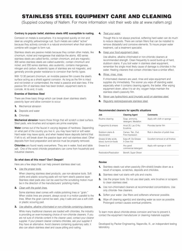
STAINLESS STEEL EQUIPMENT CARE AND CLEANING(Suppied courtesy of Nafem. For more information visit their web site at www.nafem.org)
Contrary to popular belief, stainless steels ARE susceptible to rusting.
Corrosion on metals is everywhere. It is recognized quickly on iron andsteel as unsightly yellow/orange rust. Such metals are called “active”because they actively corrode in a natural environment when their atomscombine with oxygen to form rust.
Stainless steels are passive metals because they contain other metals, likechromium, nickel and manganese that stabilize the atoms. 400 seriesstainless steels are called ferritic, contain chromium, and are magnetic;300 series stainless steels are called austenitic, contain chromium andnickel; and 200 series stainless, also austenitic, contains manganese,nitrogen and carbon. Austenitic types of stainless are not magnetic, andgenerally provide greater resistance to corrosion than ferritic types.
With 12-30 percent chromium, an invisible passive film covers the steel’ssurface acting as a shield against corrosion. As long as the film is intactand not broken or contaminated, the metal is passive and stain-less. If thepassive film of stainless steel has been broken, equipment starts tocorrode. At its end, it rusts.
Enemies of Stainless Steel
There are three basic things which can break down stainless steel’spassivity layer and allow corrosion to occur.
1. Mechanical abrasion
2. Deposits and water
3. Chlorides
Mechanical abrasion means those things that will scratch a steel surface.Steel pads, wire brushes and scrapers are prime examples.
Water comes out of the faucet in varying degrees of hardness. Dependingon what part of the country you live in, you may have hard or soft water.Hard water may leave spots, and when heated leave deposits behind thatif left to sit, will break down the passive layer and rust stainless steel. Otherdeposits from food preparation and service must be properly removed.
Chlorides are found nearly everywhere. They are in water, food and tablesalt. One of the worst chloride perpetrators can come from household andindustrial cleaners.
So what does all this mean? Don’t Despair!
Here are a few steps that can help prevent stainless steel rust.
1. Use the proper tools.
When cleaning stainless steel products, use non-abrasive tools. Softcloths and plastic scouring pads will not harm steel’s passive layer.Stainless steel pads also can be used but the scrubbing motion mustbe in the direction of the manufacturers’ polishing marks.
2. Clean with the polish lines.
Some stainless steel comes with visible polishing lines or “grain.”When visible lines are present, always scrub in a motion parallel to thelines. When the grain cannot be seen, play it safe and use a soft clothor plastic scouring pad.
3. Use alkaline, alkaline chlorinated or non-chloride containing cleaners.
While many traditional cleaners are loaded with chlorides, the industryis providing an ever-increasing choice of non-chloride cleaners. If youare not sure of chloride content in the cleaner used, contact your cleanersupplier. If your present cleaner contains chlorides, ask your supplier ifthey have an alternative. Avoid cleaners containing quaternary salts; italso can attack stainless steel and cause pitting and rusting.
4. Treat your water.
Though this is not always practical, softening hard water can do muchto reduce deposits. There are certain filters that can be installed toremove distasteful and corrosive elements. To insure proper watertreatment, call a treatment specialist.
5. Keep your food equipment clean.
Use alkaline, alkaline chlorinated or non-chloride cleaners atrecommended strength. Clean frequently to avoid build-up of hard,stubborn stains. If you boil water in stainless steel equipment,remember the single most likely cause of damage is chlorides in thewater. Heating cleaners that contain chlorides have a similar effect.
6. Rinse, rinse, rinse.
If chlorinated cleaners are used, rinse and wipe equipment andsupplies dry immediately. The sooner you wipe off standing water,especially when it contains cleaning agents, the better. After wipingequipment down, allow it to air dry; oxygen helps maintain thestainless steel’s passivity film.
7. Never use hydrochloric acid (muriatic acid) on stainless steel.
8. Regularly restore/passivate stainless steel.
Recommended cleaners for specific situations
Job Cleaning Agent Comments
Routine cleaning Soap, ammonia, Apply with cloth or spongedetergent, Medallion
Fingerprints & smears Arcal 20, Lac-O-Nu Provides barrier filmEcoshine
Stubborn stains & Cameo, Talc, Zud, Rub in direction of polish linesdiscoloration First Impression
Grease & fatty acids, Easy-off, De-Grease Excellent removal on all finishesblood, burnt-on-foods It Oven Aid
Grease & oil Any good Apply with sponge or clothcommercial detergent
Restoration/Passivation Benefit, Super Sheen
Review
1. Stainless steels rust when passivity (film-shield) breaks down as aresult of scrapes, scratches, deposits and chlorides.
2. Stainless steel rust starts with pits and cracks.
3. Use the proper tools. Do not use steel pads, wire brushes or scrapersto clean stainless steel.
4. Use non-chlorinated cleaners at recommended concentrations. Useonly chloride- free cleaners.
5. Soften your water. Use filters and softeners whenever possible.
6. Wipe off cleaning agent(s) and standing water as soon as possible.Prolonged contact causes eventual problems.
To learn more about chloride-stress corrosion and how to prevent it,contact the equipment manufacturer or cleaning materials supplier.
Developed by Packer Engineering, Naperville, Ill., an independent testinglaboratory.

Disassembly
1. Disconnect power from kettle.
2. Remove console cover from top of kettle'sconsole.
3. Remove locknut and lockwasher from insideconsole.
4. Remove shoulder bold from latch.
5. Clean all parts.
Re-Assembly
6. Apply locktight toshoulderbolt whereillustrated. Replaceshoulder bolt and latch and tighten firmly.
7. Replace lockwasher and locknut inside the console and tighten firmly.
8. Test Marine Lock. See Marine Lock TestingProcedure.
9. Replace console cover.
MARINE LOCKUse a small nylon bristle brush to remove foodand debris from pivot point. If lock is still stickinghave maintenance disassemble and clean piecesindividually and reassemble.
Latch
Shoulder Bolt
Carefully applylocktight to the
final two threads.Lockwasher
Locknut
MARINE LOCK TESTING PROCEDURE
1. Check that lock clears stop pin on side boxwithout rubbing when kettle is tilted (Figure A).
2. Check side to side play. Lock should remainfully over stop pin when pushed to it'smaximum side to side play (Figure B).
3. Check that the kettle when pushed fullyupright moves the lock to a closed position.To check this:
A/ Hold the latch firmly in the unlockedposition while tilting the kettle back to anupright position.
B/ The kettle sidebox will force the lock into anew position.
C/ Hold the lock in this position and try to tiltthe kettle forward. The latch should preventthe kettle from tilting.
Side Box
Lockwasher
Locknut
Shoulder Bolt ConsoleFigure B
(Top View)
Side to Side Play
Stop Pin onSidebox Marine Lock
(Latch)
Figure A(Side View)
4. Check shoulder bolt is firmly seated againstconsole body.
5. Check on inside of console box that shoulderbolt locknut is secure.

FAUCET ASSEMBLY
ITEM PART DESCRIPTION QTY.NO. NO.
1. KE50825-2 3/4" Spout (KET-3/6/12/20-T) . . . . . . . .1
KE50825-9 3/4" Spout (TKET-3/6/12-T) . . . . . . . . .1
2. FA95022 Retaining Ring . . . . . . . . . . . . . . . . . .1
3. FA05002-19 "O" Ring . . . . . . . . . . . . . . . . . . . . . . . .1
4. KE51736 Long Faucet Nut . . . . . . . . . . . . . . . . .1
5. SE50020 Hot Water Stem Assembly . . . . . . . . .1(Double Pantry only)
6. SE50021 Cold Water Stem Assembly . . . . . . . .1
7. KE51401 Single Pantry Body . . . . . . . . . . . . . . .1(c/w Item No. 6)
8. KE50335 Adapter Washer . . . . . . . . . . . . . . . . .1(Single Pantry only)
9. KE51403 Double Pantry Body . . . . . . . . . . . . . .1(c/w Item No. 5&6)
10. KE54159 Faucet Mounting Bracket . . . . . . . . . .1
11. FA11258 Hex Cap Screw . . . . . . . . . . . . . . . . . .2
12. FA30505 Washer . . . . . . . . . . . . . . . . . . . . . . . .2
13. FA21008 Hex Nut . . . . . . . . . . . . . . . . . . . . . . . .2
14. SE50447 Washer Horseshoe . . . . . . . . . . . . . . .1
1
1
2
2
3
3
4
4
5
9
10
10
13
8
1211
13
14
12
11
7
6
6
SERVICE PARTSWARRANTYOur Company supports a worldwide network of Maintenance and Repair Centers. Contact your nearestMaintenance and Repair Centre for replacement parts, service, or information regarding the propermaintenance and repair of your cooking equipment
In order to preserve the various agency safety certification (UL, NSF, ASME/Ntl. Bd., etc.), only factory-supplied replacement parts should be used. The use of other than factory supplied replacement parts willvoid warranty.

KETTLE BOTTOM & SIDE
ITEM NO. PART NO. DESCRIPTION QTY.
1. KE50556-1 Probe, Low Water . . . . . . . . . . . . . . . . . . . . . . . . . . . . . . . . . . . . . . . . . .1
2. KE54941-5 Safety Valve, 50 PSI, 1/2" (North America) . . . . . . . . . . . . . . . . . . . . . .1
KE54941-31 Safety Valve, 50 PSI, 1/2", (Europe) . . . . . . . . . . . . . . . . . . . . . . . . . . . .1
3. KE52455 Bottom Cover Gasket, 3 gallon kettle . . . . . . . . . . . . . . . . . . . . . . . . . .1
KE52456 Bottom Cover Gasket, 6 gallon kettle . . . . . . . . . . . . . . . . . . . . . . . . . .1
KE52457 Bottom Cover Gasket, 12 gallon kettle . . . . . . . . . . . . . . . . . . . . . . . . .1
KE52459 Bottom Cover Gasket, 20 gallon kettle . . . . . . . . . . . . . . . . . . . . . . . . .1
4. KE00515 Thermistor Assembly . . . . . . . . . . . . . . . . . . . . . . . . . . . . . . . . . . . . . . .1
5. KE55069-5 Safety Thermostat (140º C) . . . . . . . . . . . . . . . . . . . . . . . . . . . . . . . . . .1
6. FA11145 Screw . . . . . . . . . . . . . . . . . . . . . . . . . . . . . . . . . . . . . . . . . . . . . . . . . .2-12
7. FA21007 Nut . . . . . . . . . . . . . . . . . . . . . . . . . . . . . . . . . . . . . . . . . . . . . . . . . . . .2-12
8. Pressure Gauge
KE000714-4 For units built prior to February 2005 . . . . . . . . . . . . . . . . . . . . . . . . . . .1
KE50429-5 For units built after January 2005 . . . . . . . . . . . . . . . . . . . . . . . . . . . . . .1
6 7
1
4
ElementTerminals
3
5
2
8

2
3
4 5
1
CORD & PLUG OPTION
ITEM NO. PART NO. DESCRIPTION QTY.
FOR KET-6-T (SW) (200-240VAC, 3PH, 50/60Hz1. KE02113-1 Cord Plug Assembly . . . . . . . . . . . . . . . . . . . . . . . . . . . . . . . . . . . . . . . .1
2. KE54819-1 Plug (30A) . . . . . . . . . . . . . . . . . . . . . . . . . . . . . . . . . . . . . . . . . . . . . . . .1
3. KE54820-1 Receptacle (30A) . . . . . . . . . . . . . . . . . . . . . . . . . . . . . . . . . . . . . . . . . .1
4. KE54821-2 Electrical Cord (10/4) . . . . . . . . . . . . . . . . . . . . . . . . . . . . . . . . . . . . . . .1
5. KE54721-3 Cord Connector . . . . . . . . . . . . . . . . . . . . . . . . . . . . . . . . . . . . . . . . . . .1
FOR KET-6-T (HW), KET-12-T (SW), (200-240VAC, 3PH, 50/60Hz1. KE02113-2 Cord Plug Assembly . . . . . . . . . . . . . . . . . . . . . . . . . . . . . . . . . . . . . . . .1
2. KE54819-2 Plug (50A) . . . . . . . . . . . . . . . . . . . . . . . . . . . . . . . . . . . . . . . . . . . . . . . .1
3. KE54820-2 Receptacle (50A) . . . . . . . . . . . . . . . . . . . . . . . . . . . . . . . . . . . . . . . . . .1
4. KE54821-3 Electrical Cord (8/4) . . . . . . . . . . . . . . . . . . . . . . . . . . . . . . . . . . . . . . . .1
5. KE54721-4 Cord Connector . . . . . . . . . . . . . . . . . . . . . . . . . . . . . . . . . . . . . . . . . . .1
FOR KET-12-T (HW) (200-240VAC, 3PH, 50/60Hz1. KE02113-3 Cord Plug Assembly . . . . . . . . . . . . . . . . . . . . . . . . . . . . . . . . . . . . . . . .1
2. KE54819-2 Plug (50A) . . . . . . . . . . . . . . . . . . . . . . . . . . . . . . . . . . . . . . . . . . . . . . . .1
3. KE54820-2 Receptacle (50A) . . . . . . . . . . . . . . . . . . . . . . . . . . . . . . . . . . . . . . . . . .1
4. KE54821-4 Electrical Cord (6/4) . . . . . . . . . . . . . . . . . . . . . . . . . . . . . . . . . . . . . . . .1
5. KE54721-5 Cord Connector . . . . . . . . . . . . . . . . . . . . . . . . . . . . . . . . . . . . . . . . . . .1
Not available for KET-20-T or Twin Kettles

CONSOLE COMPONENTS & MARINE LOCK
6
4
6
7
109
8
11
13
25
23
5
2
3
1
14 15
16
18
19
20
21
17
24
22

CONSOLE COMPONENTS & MARINE LOCKITEM NO. PART NO. DESCRIPTION QTY.
Single / Twin
1. SE00113 Potentiometer with ON/OFF Switch, c/w Item #2 . . . . . . . . . . . . . . . . . . . . . . . 1 / 2
2. KE51005 Rubber Boot . . . . . . . . . . . . . . . . . . . . . . . . . . . . . . . . . . . . . . . . . . . . . . . . . . . 1 / 2
3. KE50569-1 Knob, Potentiometer . . . . . . . . . . . . . . . . . . . . . . . . . . . . . . . . . . . . . . . . . . . . . 1 / 2
4. SE003013-1 Red L.E.D Replacement Kit., (includes LED KE50567-1 & "O" Ring) . . . . . . . 1 / 2
5. SE003013-2 Green L.E.D Replacement Kit., (includes LED KE50568-1 & "O" Ring) . . . . . 1 / 2
6. FA05002-18 "O" Ring . . . . . . . . . . . . . . . . . . . . . . . . . . . . . . . . . . . . . . . . . . . . . . . . . . . . . . 2 / 4
7. KE55319 Bearing, Bronze Trunnion, 6 & 12 gallon . . . . . . . . . . . . . . . . . . . . . . . . . . . . . 1 / 2
KE54234 Bearing, Bronze Trunnion, 3 & 20 gallon . . . . . . . . . . . . . . . . . . . . . . . . . . . . . 1 / 2
8. FA05002-20 "O" Ring . . . . . . . . . . . . . . . . . . . . . . . . . . . . . . . . . . . . . . . . . . . . . . . . . . . . . . 1 / 2
9. FA19184 Allen Screw . . . . . . . . . . . . . . . . . . . . . . . . . . . . . . . . . . . . . . . . . . . . . . . . . . . . 2/ 4
10. SK50047 Collar, Trunnion Lock . . . . . . . . . . . . . . . . . . . . . . . . . . . . . . . . . . . . . . . . . . . . 1 / 2
11. FA21024 Hex Nut, 5/16-18 . . . . . . . . . . . . . . . . . . . . . . . . . . . . . . . . . . . . . . . . . . . . . . . 1 / 2
13. KE01834 Bearing Assembly . . . . . . . . . . . . . . . . . . . . . . . . . . . . . . . . . . . . . . . . . . . . . . 1 / 2
14. KE50473 Ground Lug . . . . . . . . . . . . . . . . . . . . . . . . . . . . . . . . . . . . . . . . . . . . . . . . . . . 1 / 2
15. FA95074 Nylon Anchor Nut . . . . . . . . . . . . . . . . . . . . . . . . . . . . . . . . . . . . . . . . . . . . . . . . 4
16. FA95031 Screw . . . . . . . . . . . . . . . . . . . . . . . . . . . . . . . . . . . . . . . . . . . . . . . . . . . . . . . . . 4
17. KE54218 Console Covers (KET-3-T, KET-6-T, KET-12-T, KET-20-T, TKET-3-T) . . . . . . .1
KE542181 (TKET-6-T, TKET-12-T) . . . . . . . . . . . . . . . . . . . . . . . . . . . .1
Marine Lock18. FA15019-1 Hex Socket Shoulder Bolt . . . . . . . . . . . . . . . . . . . . . . . . . . . . . . . . . . . . . . . . 1 / 2
19. FA31029 Split Lockwasher . . . . . . . . . . . . . . . . . . . . . . . . . . . . . . . . . . . . . . . . . . . . . . . 1 / 2
20. KE02078-1 Latch, Left Hand . . . . . . . . . . . . . . . . . . . . . . . . . . . . . . . . . . . . . . . . . . . . . . . . . 1
KE02078-2 Latch, Right Hand . . . . . . . . . . . . . . . . . . . . . . . . . . . . . . . . . . . . . . . . . . . . . . . 1
21. FA21008 Hex Nut, 1/4-20 . . . . . . . . . . . . . . . . . . . . . . . . . . . . . . . . . . . . . . . . . . . . . . . . 1 / 2
22. LabelsKE95555-1 (KET-3-T, KET-6-T, KET-12-T, KET-20-T) . . . . . . . . . . . . . . . . . . . . . . . . . . . . . . . .1
KE95555-3 (TKET-3-T) . . . . . . . . . . . . . . . . . . . . . . . . . . . . . . . . . . . . . . . . . . . . . . . .1
KE95555-4 (TKET-6-T, TKET-12-T) . . . . . . . . . . . . . . . . . . . . . . . . . . . . . . . . . . . . . . . . . . . . .1
23. TransformersKE53838-11 Transformer, 380 to 415v . . . . . . . . . . . . . . . . . . . . . . . . . . . . . . . . . . . . . . . . . . .1
KE53838-12 Transformer, 440 to 480v . . . . . . . . . . . . . . . . . . . . . . . . . . . . . . . . . . . . . . . . . . .1
KE53838-13 Transformer, 600v . . . . . . . . . . . . . . . . . . . . . . . . . . . . . . . . . . . . . . . . . . . . . . . .1
24. KE54846-1 Cover Gasket, KET- 3/6/12/20-T, TKET-3-T . . . . . . . . . . . . . . . . . . . . . . . . . . . . .1
KE54846-2 Cover Gasket, TKET-6/12-T . . . . . . . . . . . . . . . . . . . . . . . . . . . . . . . . . . . . . . . . .1
25. FA95073 Round Head Square Neck Bolt . . . . . . . . . . . . . . . . . . . . . . . . . . . . . . . . . . . . . .1

NOTE: Item #14 to be tack welded flush outside in the gearbox housing (item #1). Do not damage the outside edges of the gearbox housing when tack welding.
1
14
2
2
3
78
79
3
5
6
20
19
22
23
21
25
10
11
4
1213
1615
1224
18
17
TILTING GEARBOX ASSEMBLY(12 gallon kettle only, prior to January 2002)
ITEM NO. PART NO. DESCRIPTION QTY.
1.-16. KE02062-1 TILTING GEARBOX ASSEMBLY . . . . . . . . . . . . . . . . . . . . . . . . . . . . . . . . . . . . . . . . .11. KE02060 GEARBOX HOUSING . . . . . . . . . . . . . . . . . . . . . . . . . . . . . . . . . . . . . . . . . . . . . . . . .12. KE50198 BEARING, TRUNNION . . . . . . . . . . . . . . . . . . . . . . . . . . . . . . . . . . . . . . . . . . . . . . . .23. KE54739-2 BEARING, TILT SHAFT . . . . . . . . . . . . . . . . . . . . . . . . . . . . . . . . . . . . . . . . . . . . . . . .24. KE54737 END HOUSING SPACER, TILT SHAFT, BRONZE . . . . . . . . . . . . . . . . . . . . . . . . . . . .15. KE50306-2 WASHER . . . . . . . . . . . . . . . . . . . . . . . . . . . . . . . . . . . . . . . . . . . . . . . . . . . . . . . . . . .16. KE50306-1 TILT SHAFT . . . . . . . . . . . . . . . . . . . . . . . . . . . . . . . . . . . . . . . . . . . . . . . . . . . . . . . . .17. KE52192 BEARING WASHER . . . . . . . . . . . . . . . . . . . . . . . . . . . . . . . . . . . . . . . . . . . . . . . . . .28. KE52191 BEARING . . . . . . . . . . . . . . . . . . . . . . . . . . . . . . . . . . . . . . . . . . . . . . . . . . . . . . . . . .19. KE50426-3 SPACER, WORM GEAR . . . . . . . . . . . . . . . . . . . . . . . . . . . . . . . . . . . . . . . . . . . . . . .110. KE50315 WORM GEAR . . . . . . . . . . . . . . . . . . . . . . . . . . . . . . . . . . . . . . . . . . . . . . . . . . . . . . .111. FA95005 TENSION PIN . . . . . . . . . . . . . . . . . . . . . . . . . . . . . . . . . . . . . . . . . . . . . . . . . . . . . . .112. KE54738-1 WASHER . . . . . . . . . . . . . . . . . . . . . . . . . . . . . . . . . . . . . . . . . . . . . . . . . . . . . . . . . . .213. KE02059 SEGMENT GEAR AND SPACER ASSEMBLY . . . . . . . . . . . . . . . . . . . . . . . . . . . . . . .114. KE02061 TRUNNION BEARING HOUSING HOLDER ASSEMBLY C/W BEARING . . . . . . . . . .115. FA10485 HEX HEAD BOLT . . . . . . . . . . . . . . . . . . . . . . . . . . . . . . . . . . . . . . . . . . . . . . . . . . . .116. FA20008 HEX NUT . . . . . . . . . . . . . . . . . . . . . . . . . . . . . . . . . . . . . . . . . . . . . . . . . . . . . . . . . . .117. KE54729 GEAR BOX COVER . . . . . . . . . . . . . . . . . . . . . . . . . . . . . . . . . . . . . . . . . . . . . . . . . .118. FA11146 BINDING HEAD SCREW, 8-32 X 3/8" . . . . . . . . . . . . . . . . . . . . . . . . . . . . . . . . . . . . .419. KE54750-2 TILT BRACKET . . . . . . . . . . . . . . . . . . . . . . . . . . . . . . . . . . . . . . . . . . . . . . . . . . . . . .120. KE54732 HEX HEAD BOLT . . . . . . . . . . . . . . . . . . . . . . . . . . . . . . . . . . . . . . . . . . . . . . . . . . . .121. SCREW, #10-24 X 1 1/4” . . . . . . . . . . . . . . . . . . . . . . . . . . . . . . . . . . . . . . . . . . . . . .222. KE54656-4 SUPPORT BAR TOP - END . . . . . . . . . . . . . . . . . . . . . . . . . . . . . . . . . . . . . . . . . . . .123. KE02004-3 SUPPORT BAR . . . . . . . . . . . . . . . . . . . . . . . . . . . . . . . . . . . . . . . . . . . . . . . . . . . . . .124. KE54732 HEX HEAD BOLT . . . . . . . . . . . . . . . . . . . . . . . . . . . . . . . . . . . . . . . . . . . . . . . . . . . .125. SK50403-2 BRONZE BEARING . . . . . . . . . . . . . . . . . . . . . . . . . . . . . . . . . . . . . . . . . . . . . . . . . .1

TRUNNION SHOWNFOR CLARITY
F
3, 6
& 1
2 G
ALL
ON
20 G
ALL
ON
3
6
5
7
8
9
102021
4
5
8
7
131914
18
12
11
22A
1
APPLY RTV
SEALANT
2415B
15A
23
22B
216
17
TILTING GEARBOX ASSEMBLY(3, 6, 12 & 20 gallon kettles, after January 2002)
ITEM NO. PART NO. DESCRIPTION QTY.
1. KE54738-3 WASHER S.S. (SHAFT HOLE COVER) . . . . . . . . . . . . . . . . . . . . . . . . . . . . . . . . . . .12. KE51738 BEARING SLEEVE FOR GEAR BOX . . . . . . . . . . . . . . . . . . . . . . . . . . . . . . . . . . . . .13. KE50315 WORM GEAR . . . . . . . . . . . . . . . . . . . . . . . . . . . . . . . . . . . . . . . . . . . . . . . . . . . . . . .14. FA95005 TENSION PIN . . . . . . . . . . . . . . . . . . . . . . . . . . . . . . . . . . . . . . . . . . . . . . . . . . . . . . .15. KE51891 WASHER 1 1/2" O.D. X 13/16" I.D. . . . . . . . . . . . . . . . . . . . . . . . . . . . . . . . . . . . . . .26. KE52193-1 THRUST BEARING SPACER . . . . . . . . . . . . . . . . . . . . . . . . . . . . . . . . . . . . . . . . . . .27. KE52192 THRUST WASHER . . . . . . . . . . . . . . . . . . . . . . . . . . . . . . . . . . . . . . . . . . . . . . . . . . .48. KE52191 THRUST BEARING . . . . . . . . . . . . . . . . . . . . . . . . . . . . . . . . . . . . . . . . . . . . . . . . . .29. FA30088 TILT SHAFT WASHER . . . . . . . . . . . . . . . . . . . . . . . . . . . . . . . . . . . . . . . . . . . . . . . .110. FA95008 LOCK NUT 3/4-16 . . . . . . . . . . . . . . . . . . . . . . . . . . . . . . . . . . . . . . . . . . . . . . . . . . . .111. FA19177 SET SCREW 5/16-24 X 1" . . . . . . . . . . . . . . . . . . . . . . . . . . . . . . . . . . . . . . . . . . . . .112. FA20047 JAM HEX NUT 5/16-24 . . . . . . . . . . . . . . . . . . . . . . . . . . . . . . . . . . . . . . . . . . . . . . .113. KE54927 SUPPLY WIRE PROTECTION GUARD . . . . . . . . . . . . . . . . . . . . . . . . . . . . . . . . . . .114 . KE00151-2 SEGMENT GEAR . . . . . . . . . . . . . . . . . . . . . . . . . . . . . . . . . . . . . . . . . . . . . . . . . . . .115A. KE50306-2 TILT SHAFT (3, 6 & 12 GALLON) . . . . . . . . . . . . . . . . . . . . . . . . . . . . . . . . . . . . . . . .115B. KE50375 TILT SHAFT (20 GALLON) . . . . . . . . . . . . . . . . . . . . . . . . . . . . . . . . . . . . . . . . . . . . .116. KE02057-1 TILT SHAFT BEARING ASSEMBLY . . . . . . . . . . . . . . . . . . . . . . . . . . . . . . . . . . . . . .117. KE50245 BEARING FOR GEARBOXES . . . . . . . . . . . . . . . . . . . . . . . . . . . . . . . . . . . . . . . . . .118. FA95083 WOODRUFF KEY #808 . . . . . . . . . . . . . . . . . . . . . . . . . . . . . . . . . . . . . . . . . . . . . . .119. FA19500-4 SET SCREW, 1/4-28 X 3/4 . . . . . . . . . . . . . . . . . . . . . . . . . . . . . . . . . . . . . . . . . . . . .220. KE55431 NUT, SLOTTED . . . . . . . . . . . . . . . . . . . . . . . . . . . . . . . . . . . . . . . . . . . . . . . . . . . . .121. KE55432 COTTER PIN, 3/32 X 1 3/4 . . . . . . . . . . . . . . . . . . . . . . . . . . . . . . . . . . . . . . . . . . . .122A. KE55433-1 SPACER, SAFETY (3, 6 & 12 GALLON) . . . . . . . . . . . . . . . . . . . . . . . . . . . . . . . . . . .122B. KE55433-2 SPACER, SAFETY (20 GALLON) . . . . . . . . . . . . . . . . . . . . . . . . . . . . . . . . . . . . . . . .123. KE00508 HANDWEEL ASSEMBLY . . . . . . . . . . . . . . . . . . . . . . . . . . . . . . . . . . . . . . . . . . . . . .124 FA19505 SET SCREW 3/8-24 X 3/8 . . . . . . . . . . . . . . . . . . . . . . . . . . . . . . . . . . . . . . . . . . . . .1

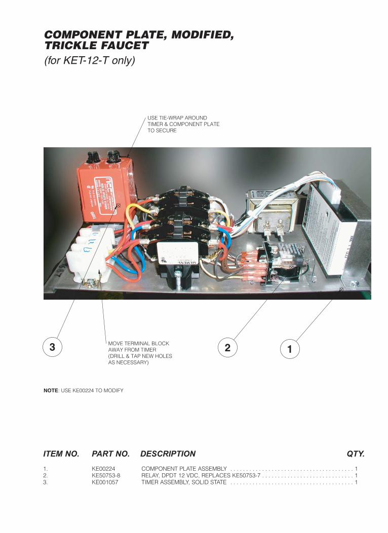
123 MOVE TERMINAL BLOCKAWAY FROM TIMER(DRILL & TAP NEW HOLESAS NECESSARY)
USE TIE-WRAP AROUNDTIMER & COMPONENT PLATETO SECURE
NOTE: USE KE00224 TO MODIFY
COMPONENT PLATE, MODIFIED,TRICKLE FAUCET(for KET-12-T only)
ITEM NO. PART NO. DESCRIPTION QTY.
1. KE00224 COMPONENT PLATE ASSEMBLY . . . . . . . . . . . . . . . . . . . . . . . . . . . . . . . . . . . . . . . 12. KE50753-8 RELAY, DPDT 12 VDC, REPLACES KE50753-7 . . . . . . . . . . . . . . . . . . . . . . . . . . . . . 13. KE001057 TIMER ASSEMBLY, SOLID STATE . . . . . . . . . . . . . . . . . . . . . . . . . . . . . . . . . . . . . . . 1

1
2
3
4
5
6
7
8
910
11
12
13
14
15
16
15
17
18
19 20
17 SOLDER WITH96.5 Sn-3.5 Ag3 mm LEAD-FREEWIRE & USE SOLDERING PASTE
NOTE: WRAP BALANCINGVALVE WITH A WET RAGWHILE SOLDERING TO AVOID BURNING OF INSIDE RUBBER LINING OF VALVE
SEE TYP.DETAIL 'A'
INSTALL VALVE WITH ARROW ON ITS LABEL TOWARDS SPOUT
DETAIL 'A'
PLUMBING, TRICKLE FAUCET(for KET-12-T only)
ITEM NO. PART NO. DESCRIPTION QTY.
1. KE601160 NIPPLE; 1/4 NPT X 7/8 BRASS . . . . . . . . . . . . . . . . . . . . . . . . . . . . . . . . . . . . . . . . . .12. KE601045 AUTO BALANCING VALVE . . . . . . . . . . . . . . . . . . . . . . . . . . . . . . . . . . . . . . . . . . . .13. FI05025 STREET ELBOW, 1/2" PLATED . . . . . . . . . . . . . . . . . . . . . . . . . . . . . . . . . . . . . . . . .14. KE601046 SWEAT FITTING, COPPER, 1/2 NPT MALE X 1/2 FEMALE . . . . . . . . . . . . . . . . . . . .25. KE601047 COPPER PIPE INSERT . . . . . . . . . . . . . . . . . . . . . . . . . . . . . . . . . . . . . . . . . . . . . . .26. KE54834-5 SOLENOID VALVE . . . . . . . . . . . . . . . . . . . . . . . . . . . . . . . . . . . . . . . . . . . . . . . . . . .17. KE54834-15 SOLENOID VALVE . . . . . . . . . . . . . . . . . . . . . . . . . . . . . . . . . . . . . . . . . . . . . . . . . . .18. FI00062 1/2 ELBOW, BRASS . . . . . . . . . . . . . . . . . . . . . . . . . . . . . . . . . . . . . . . . . . . . . . . . . .19. KE601049 ADAPTOR, 1/2 NPT M X 1/8 NPT F . . . . . . . . . . . . . . . . . . . . . . . . . . . . . . . . . . . . . .110. FI05199-6 COMPRESSION FITTING, 1/8 MPT X 1/4 TUBE . . . . . . . . . . . . . . . . . . . . . . . . . . . .111. FI05198-4 COMPRESSION ELBOW, 1/4 TUBE X 1/4 MPT . . . . . . . . . . . . . . . . . . . . . . . . . . . . .112. KE601050 COPPER TUBING . . . . . . . . . . . . . . . . . . . . . . . . . . . . . . . . . . . . . . . . . . . . . . . . . . .113. KE601052 ADAPTOR, 1/2 NPT M X 1/4 NPT F . . . . . . . . . . . . . . . . . . . . . . . . . . . . . . . . . . . . . .114. FI00178 BRASS TEE, 1/2 . . . . . . . . . . . . . . . . . . . . . . . . . . . . . . . . . . . . . . . . . . . . . . . . . . . . .115. FI00596 BRASS NIPPLE, 1/2 X 1 1/2 . . . . . . . . . . . . . . . . . . . . . . . . . . . . . . . . . . . . . . . . . . .216. KE54353 WASHER . . . . . . . . . . . . . . . . . . . . . . . . . . . . . . . . . . . . . . . . . . . . . . . . . . . . . . . . . .117. FI00356 REDUCER 3/4 X 1/2 . . . . . . . . . . . . . . . . . . . . . . . . . . . . . . . . . . . . . . . . . . . . . . . . .218. FI00629-36 BRASS NIPPLE, 3/4 X 1 1/2 LONG . . . . . . . . . . . . . . . . . . . . . . . . . . . . . . . . . . . . . .119. FI00179 BRASS TEE, 3/4 . . . . . . . . . . . . . . . . . . . . . . . . . . . . . . . . . . . . . . . . . . . . . . . . . . . . .120. SD50098 LOCKNUT, GALVANIZED, 3/4 . . . . . . . . . . . . . . . . . . . . . . . . . . . . . . . . . . . . . . . . . .1
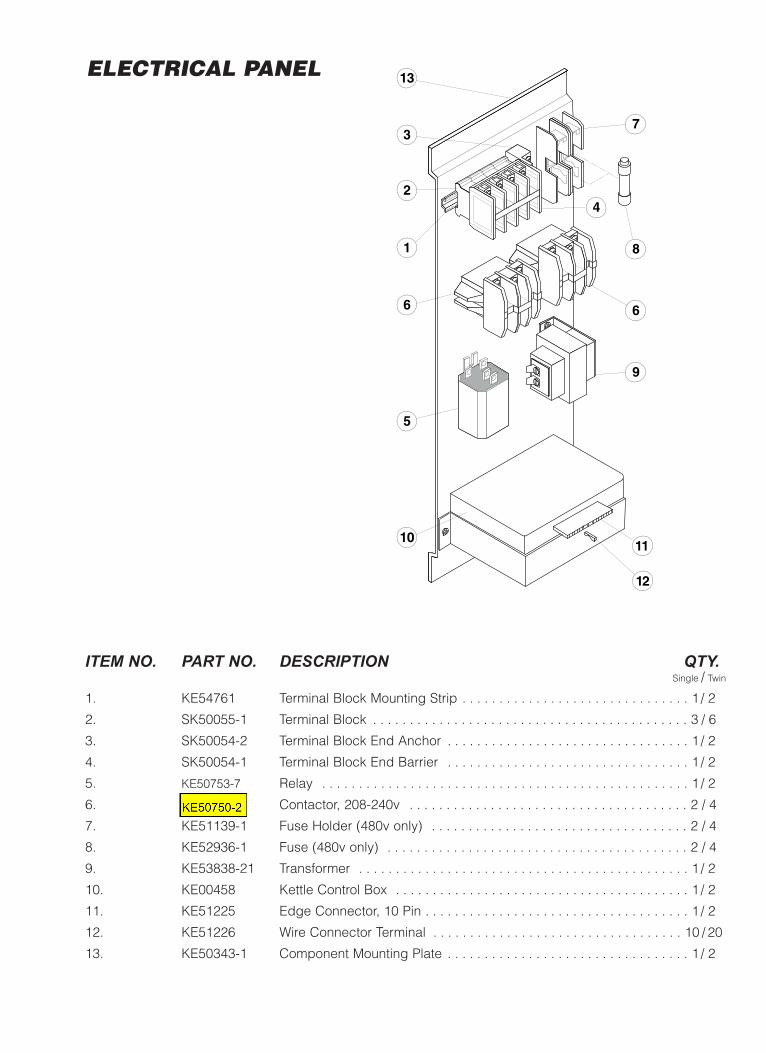
ELECTRICAL PANEL
ITEM NO. PART NO. DESCRIPTION QTY.Single / Twin
1. KE54761 Terminal Block Mounting Strip . . . . . . . . . . . . . . . . . . . . . . . . . . . . . . . 1 / 2
2. SK50055-1 Terminal Block . . . . . . . . . . . . . . . . . . . . . . . . . . . . . . . . . . . . . . . . . . . 3 / 6
3. SK50054-2 Terminal Block End Anchor . . . . . . . . . . . . . . . . . . . . . . . . . . . . . . . . . 1 / 2
4. SK50054-1 Terminal Block End Barrier . . . . . . . . . . . . . . . . . . . . . . . . . . . . . . . . . 1 / 2
5. KE50753-7 Relay . . . . . . . . . . . . . . . . . . . . . . . . . . . . . . . . . . . . . . . . . . . . . . . . . . 1 / 2
6. KE50749-2 Contactor, 208-240v . . . . . . . . . . . . . . . . . . . . . . . . . . . . . . . . . . . . . . 2 / 4
7. KE51139-1 Fuse Holder (480v only) . . . . . . . . . . . . . . . . . . . . . . . . . . . . . . . . . . . 2 / 4
8. KE52936-1 Fuse (480v only) . . . . . . . . . . . . . . . . . . . . . . . . . . . . . . . . . . . . . . . . . 2 / 4
9. KE53838-21 Transformer . . . . . . . . . . . . . . . . . . . . . . . . . . . . . . . . . . . . . . . . . . . . . 1 / 2
10. KE00458 Kettle Control Box . . . . . . . . . . . . . . . . . . . . . . . . . . . . . . . . . . . . . . . . 1 / 2
11. KE51225 Edge Connector, 10 Pin . . . . . . . . . . . . . . . . . . . . . . . . . . . . . . . . . . . . 1 / 2
12. KE51226 Wire Connector Terminal . . . . . . . . . . . . . . . . . . . . . . . . . . . . . . . . . . 10 / 20
13. KE50343-1 Component Mounting Plate . . . . . . . . . . . . . . . . . . . . . . . . . . . . . . . . . 1 / 2
1 8
6
11
12
9
7
42
6
5
10
3
13ELECTRICAL PANEL
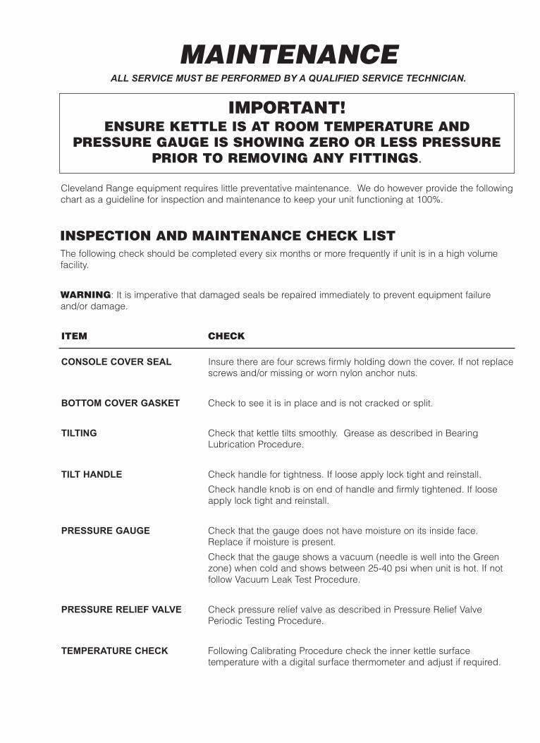
Cleveland Range equipment requires little preventative maintenance. We do however provide the followingchart as a guideline for inspection and maintenance to keep your unit functioning at 100%.
INSPECTION AND MAINTENANCE CHECK LISTThe following check should be completed every six months or more frequently if unit is in a high volumefacility.
WARNING: It is imperative that damaged seals be repaired immediately to prevent equipment failureand/or damage.
ITEM CHECK
CONSOLE COVER SEAL Insure there are four screws firmly holding down the cover. If not replacescrews and/or missing or worn nylon anchor nuts.
BOTTOM COVER GASKET Check to see it is in place and is not cracked or split.
TILTING Check that kettle tilts smoothly. Grease as described in BearingLubrication Procedure.
TILT HANDLE Check handle for tightness. If loose apply lock tight and reinstall.
Check handle knob is on end of handle and firmly tightened. If looseapply lock tight and reinstall.
PRESSURE GAUGE Check that the gauge does not have moisture on its inside face.Replace if moisture is present.
Check that the gauge shows a vacuum (needle is well into the Greenzone) when cold and shows between 25-40 psi when unit is hot. If notfollow Vacuum Leak Test Procedure.
PRESSURE RELIEF VALVE Check pressure relief valve as described in Pressure Relief ValvePeriodic Testing Procedure.
TEMPERATURE CHECK Following Calibrating Procedure check the inner kettle surfacetemperature with a digital surface thermometer and adjust if required.
MAINTENANCEALL SERVICE MUST BE PERFORMED BY A QUALIFIED SERVICE TECHNICIAN.
IMPORTANT! ENSURE KETTLE IS AT ROOM TEMPERATURE AND
PRESSURE GAUGE IS SHOWING ZERO OR LESS PRESSURE PRIOR TO REMOVING ANY FITTINGS.

BEARING LUBRICATINGPROCEDURE
1. Remove console cover.
2. Loosen two Allen screws on locking ring.
3. Pull locking ring to center of trunnion.
5. Clean newly exposed sections of trunnion.
6. Grease trunnion between kettle and console.
7. Repack outer needle bearing.
8. Push kettle back in place.
10. Reinstall trunnion and lock collar.
11. Replace console cover.
4. Pull kettle twoinches awayfrom consoleand rest onsupport block.

CALIBRATING PROCEDURE1. Insure the unit has a vacuum before you begin
calibrating procedures. If unit requires venting referto KETTLE VENTING INSTRUCTIONS.
2. Set On-Off Switch/Temperature Control to "10" (Max.).
3. Allow the unit to cycle twice.
4. Check temperature of the inner kettle surface witha digital surface thermometer.
5. Temperature should be between 260° F and 265° F.
6. Using a screw driver adjust temperature by turningthe potentiometer on the black box. Turn very little.Turn clockwise to INCREASES and counter-clockwise to DECREASE temperature.
7. Allow the unit to cycle twice.
8. Check temperature of the inner kettle surface witha digital surface thermometer.
9. Repeat steps 4. through 8. until unit is calibrated.
Pressure Relief Valve/Gauge Assembly Drawing
PRESSURE RELIEF VALVEPERIODIC TESTINGPROCEDUREMost insurance agencies require periodic testing of
pressure relief valves used on pressure vessels. Thisprocedure will allow you to safely and quickly test yourkettle's pressure relief valve. We recommend this test beperformed twice a year.
NOTE: The following instruction is intended for use byqualified service personnel.
WARNING: Kettle surface will be hot and steam will bereleased during testing. Take necessary precautionsincluding the use of gloves and eye protection toprevent personal injury.
1. With the kettle empty, set On-Off Switch/TemperatureControl to "10" (Max.). Allow the kettle to heat untilthe unit cycles off.
2. Switch On-Off Switch/Temperature Control to "0" (Off)and disconnect main power at fused disconnect switch.
3. Stand to the side of the pressure relief valvedischarge tube and pull valve open for amaximum of one second. Repeat test three tofour times. Each time the mechanism should movefreely and be accompanied by a rapid escape ofsteam.
If valve appears to be sticking replace pressure reliefvalve.
If foreign material is discharged then drain kettle andreplace pressure relief valve.
See KETTLE JACKET CLEANOUT AND PASSIVATIONPROCEDURES for full instructions on the correct methodfor refilling kettle jacket.
WARNING: Improper refilling of kettle jacket will resultin irreversible damage to unit.
NOTE: Rust inhibitor is purchased locally. Readdirections and do not exceed manufacturer'srecommendation (excessive rust inhibitor can alsocause solidification).
DANGER: PRESSURE RELIEFVALVE WILL EXHAUST HIGHTEMPERATURE STEAM. CONTACTWITH SKIN COULD RESULT INSERIOUS BURNS. KEEP FACE,
HANDS AND BODY CLEAR OF DISCHARGE.
DANGER: WORKING ON MACHINESWITH POWER COULD RESULT INSEVERE ELECTRICAL SHOCK.
WARNING: IMPROPER REFILLING OFKETTLE JACKET WILL RESULT INIRREVERSIBLE DAMAGE TO UNIT.
PressureGauge
PressureReliefValve

3. Pull Pressure Relief Valve (A) open to insure vesselis not pressurized.
4. Remove Pressure Relief Valve (A).
5. Replace Pressure Relief Valve (A) with Street Elbow (B).
6. Add distilled water (C) through the Street Elbow (B),using a funnel if necessary. Refer to Distilled WaterRequirements chart for the proper amount required.
7. Apply a thread sealant (i.e. Teflon tape) to thePressure Relief Valve's (A) thread and replace.
8. Restore power to unit at the fused disconnect switch.
9. The kettle must now be vented. (Refer to theKETTLE VENTING INSTRUCTIONS).
Pressure Relief Valve/Gauge Assembly Drawing
KETTLE VENTING INSTRUCTIONS
RESERVOIR FILLPROCEDURESThe kettle's water level must be maintained at the proper level tosubmerge the heater elements. Under normal operatingconditions, the sealed water reservoir should never require theaddition of water.
If the red "low water" light comes on during use (while the kettle isin an upright position), the water level has reached a critically lowlevel. The low water protection control has automatically shut offthe heater elements. The following procedure must be completedbefore further use:
NOTE: Have a qualified service technician repair the leakageproblem and add water to the unit. Ensure that the red "low water"light is on when the kettle is upright. On tilting kettles, it is normalfor the red light to come on when the kettle is in a tilted position, asthe elements are not submerged in water at this point.
DISTILLED WATER REQUIREMENTS
1. Ensure kettle is at roomtemperature and pressuregauge showing zero or lesspressure.
2. Shut off power to the kettle atthe fused disconnect switch.
When Red “Low WaterKettle Light” comes Capacity on, add Distilled Water
3 gallon 50 ounces
6 gallon 70 ounces
12 gallon 120 ounces
20 gallon 1 gallon
1. Set On-Off Switch/TemperatureControl to "10" (Max.). Heatthe empty kettle until unitcycles off.
2. Vent kettle by pulling safetyvalve ring 8-10 times in short2-3 second blasts with a 5second interval betweenpulls.
NOTE: If unit cycles ON, stopventing and wait for kettle tocycle OFF before continuing.
3. Turn kettle OFF. Add coldwater to kettle until its surfacetemperature is below 100°F.The pressure gauge needleshould be in the green zone,indicating a vacuum in thekettle’s jacket.
2
3
5 6
7
8
9
1
4
10
OFF
50
0
100150 200
250
300
350
400
40
50
60
0
10
20 30
psi kPa
VEN
TAI
R
50
0
100150 200
250
300
350
400
40
50
60
0
10
20 30
psi kPa
VEN
TAI
R
50
0
100150 200
250
300
350
400
40
50
60
0
10
20 30
psi kPa
VEN
TAI
R
PressureGauge
PressureReliefValve
The following venting procedure should be followed when theVacuum/Pressure Gauge needle is in the "VENT AIR" zone:
NOTE: Check for and eliminate leaks prior to venting(See REPAIRING LEAKS IN STEAM JACKETED KETTLEFITTINGS).
A.* RemovePressure
ReliefValve
B. Attach Street
Elbow
C. Fill unit via Street Elbow
*Important- Pull ring on Pressure Relief Valve prior to removal to insure vessel is not pressurized.

VACUUM LEAK TESTPROCEDUREIf the kettle will not hold vacuum, test for leaks at:
A. Water Level Probe (remove bottom cover).
B. Pressure Relief Valve.
C. Pressure Gauge.
LEAK TEST PROCEDURE:1. Heat kettle until unit cycles off.
2. Shut off power to the kettle at the fuseddisconnect switch.
3. Spread Bubble Type Leak Detector oversuspected areas and watch closely forbubbles.
4. Repair areas as required.
REPAIRING LEAKS IN STEAM JACKETED KETTLE FITTINGSIf unit will not hold a vacuum the most likely cause is a leak at one of the fittings.
Often, the easiest way to eliminate a leak is reseal the suspect areas.
1. Water Level Probe Remove, clean threads, apply teflon thread sealant and reinstall.
2. Pressure Relief Valve A/ Inspect for signs of leaks. Replace if required.
B/ Remove, clean threads, apply teflon thread sealant and reinstall.
3. Pressure Gauge A/ Inspect face of gauge. If it contains moisture on the inside of face replace.
B/ Remove, clean threads, apply teflon thread sealant and reinstall.
PRESSUREGAUGE
WATER LEVELPROBE
PRESSURERELIEFVALVE

KETTLE JACKET CLEANOUT AND PASSIVATION PROCEDURESThe following procedure should be preformed at least once every three years to prevent possible corrosionand ensure the optimum life of the kettle.
DESCRIPTION - Molyfilm 315 inhibits corrosion instainless steel and copper. A pH buffer is present toassist in maintaining the appropriate pH to assist incorrosion inhibition.
DISPOSAL - Follow all Federal, State and local codeswhen disposing of product.
SHELF LIFE - Molyfilm 315’s effectiveness willdiminish after three years.
REFILL QUANTITIES (ORDERING INFO: 1 LiterMolyfilm 315 Rust Inhibitor - Part# KE600340-1)
IMPORTANT: To ensure satisfactory mixing follow theMIXING / FILLING PROCEDURE described below.
Kettle Size Volume of Water Volume of Molyfilm 315U.S. Gal. Liters oz. cc (ml.)
3 U.S. Gal. 0.5 1.8 0.7 196 U.S. Gal. 1.3 4.9 1.8 5112 U.S. Gal. 2 7.6 2.8 8020 U.S. Gal. 3.8 14.2 5.1 150
MIXING / FILLING PROCEDURE1. Refer to chart to determine the required volumes of
water and Molyfilm 315.
2. In a separate container mix 1/2 gallon of the requiredvolume of water with the total required volume ofMolyfilm 315.
3. Pour mixture into kettle.
4. Pour the remaining required volume of water into kettle.
WARNING:IMPROPER REFILLING OF KETTLE JACKET WILL
RESULT IN IRREVERSIBLE DAMAGE TO UNIT.
DANGER:MOLYFILM 315 IS CORROSIVE, AVOID
CONTACT WITH SKIN AND EYES.
DANGER:AVOID INHALATION - VAPORS FROM
MOLYFILM 315 MAY BE HARMFUL OR FATAL.
REFILLING UNIT1. Apply a thread sealant (i.e. Teflon tape) to the low
water level probe threads and replace.2. Fill kettle jacket with a mixture of water and
Molyfilm 315 (see REFILL QUANTITIES chart).3. Remove street elbow. 4. Apply a thread sealant (i.e. Teflon tape) to the
pressure relief valve's thread and replace.5. Restore power to unit at the fused disconnect switch.6. Vent kettle. See Kettle Venting Instructions for
proper procedure.
RemovePressureReliefValve
AttachStreetElbow
Fill unit viaStreet Elbow
Important- Pull pressure relief valve ring open to insure vessel is not pressurized.
Low WaterLevel Probe
1. Ensure kettle is at room temperatureand pressure gauge showing zeroor less pressure.
2. Shut off power to the kettle at thefused disconnect switch.
3. Pull pressure relief valve ring opento insure vessel is not pressurized.
4. Pull pressure relief valve ring open to insure vesselis not pressurized.
5. Remove pressure relief valve.6. Replace pressure relief valve with street elbow. 7. Remove bottom cover from kettle.8. Remove low water level probe and allow water to drain.9. Add water through the street elbow and flush out as
much debris as possible with water.10. Apply a thread sealant (i.e. Teflon tape) to the low
water level probe threads and replace.11. Fill kettle jacket with a mixture of water and Molyfilm
315 (see REFILL QUANTITIES chart). 12. Remove street elbow. 13. Apply a thread sealant (i.e. Teflon tape) to the
pressure relief valve's thread and replace.14. Turn kettle on, vent and heat on high for 1/2 hour.15. Cool and drain kettle as per above procedure.
50
0
100150 200
250
300
350
400
40
50
60
0
10
20 30
psi kPa
VEN
TAI
R
FLUSHING PROCEDUREWARNING: The fused disconnect switch must be offbefore removing the kettles bottom cover.
DANGER:PRESSURE RELIEF VALVE WILL
EXHAUST HIGH TEMPERATURE STEAM.CONTACT WITH SKIN COULD RESULT INSERIOUS BURNS. KEEP FACE, HANDS
AND BODY CLEAR OF DISCHARGE.
DANGER:WORKING ON MACHINES WITH
POWER COULD RESULT IN SEVEREELECTRICAL SHOCK.
DANGER:EXTREMELY HOT SURFACES.
WORK ONLY ON COLD KETTLE.
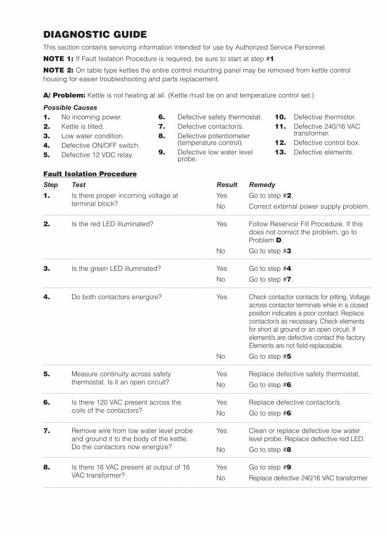
Fault Isolation Procedure
Step Test1. Is there proper incoming voltage at
terminal block?
2. Is the red LED illuminated?
3. Is the green LED illuminated?
4. Do both contactors energize?
5. Measure continuity across safetythermostat. Is it an open circuit?
6. Is there 120 VAC present across thecoils of the contactors?
7. Remove wire from low water level probeand ground it to the body of the kettle.Do the contactors now energize?
8. Is there 16 VAC present at output of 16VAC transformer?
Result RemedyYes Go to step #2.
No Correct external power supply problem.
Yes Follow Reservoir Fill Procedure. If thisdoes not correct the problem, go toProblem D.
No Go to step #3.
Yes Go to step #4.
No Go to step #7.
Yes Check contactor contacts for pitting. Voltageacross contactor terminals while in a closedposition indicates a poor contact. Replacecontactor/s as necessary. Check elementsfor short at ground or an open circuit. Ifelement/s are defective contact the factory.Elements are not field replaceable.
No Go to step #5.
Yes Replace defective safety thermostat.
No Go to step #6.
Yes Replace defective contactor/s.
No Go to step #6.
Yes Clean or replace defective low waterlevel probe. Replace defective red LED.
No Go to step #8.
Yes Go to step #9.
No Replace defective 240/16 VAC transformer.
Possible Causes1. No incoming power.2. Kettle is tilted.3. Low water condition.4. Defective ON/OFF switch.5. Defective 12 VDC relay.
6. Defective safety thermostat.7. Defective contactor/s.8. Defective potentiometer
(temperature control).9. Defective low water level
probe.
10. Defective thermistor.11. Defective 240/16 VAC
transformer.12. Defective control box.13. Defective elements.
DIAGNOSTIC GUIDE This section contains servicing information intended for use by Authorized Service Personnel.
NOTE 1: If Fault Isolation Procedure is required, be sure to start at step #1.
NOTE 2: On table type kettles the entire control mounting panel may be removed from kettle controlhousing for easier troubleshooting and parts replacement.
A/ Problem: Kettle is not heating at all. (Kettle must be on and temperature control set.)

Fault Isolation Procedure
Step Test1. In a cold state, does the pressure gauge
read in the green zone?
2. Do the contactors shut off too early?(before reaching normal maximumoperating pressure.)
3. Does the green LED remain illuminatedafter the contactors shut off?
4. Unplug control box and measure theresistance across potentiometer(temperature control). Is it approximately0 ohms at maximum and 50,000 ohms atminimum setting?
Result RemedyYes Go to step #2.
No There is air present in the jacket of thekettle. Follow Kettle Venting Procedure.If constant venting is required, there is aleak that should be corrected.
Yes Go to step #3.
No Check contactor contacts for pitting.Voltage across terminal of contactorwhile energized signifies a poorcontact. Replace contactor/s asnecessary. Check elements for short toground or open circuit. If elements aredefective, contact the factory. Elementsare not field replaceable.
Yes Replace defective safety thermostat.
No Go to step #4.
Yes Go to step #5.
No Replace defective thermistor.
Yes Go to step #6.
9. Measure continuity of ON/OFF switch/temperature control. Is it operatingproperly?
10. Unplug control box and measure theresistance across potentiometer. Is itapproximately 0 ohms at maximumsetting and 50,000 ohms at minimum?
11. Remove edge connector from controlbox. While kettle is cold or thermistor isremoved and allowed to cool, measurethe resistance between edge connector’spins #2 and #7. Is it approximately100,00 ohms?
Yes Go to step #10.
No Replace defective ON/OFF switch/temperature control.
Yes Go to step #11.
No Replace defective potentiometer(ON/OFF switch/temperature control)
Yes Spray contact cleaner on control boxterminals and edge connector. Try boxagain, if the problem still exists, replacedefective control box.
No Replace defective thermistor.
Possible Causes1. Air in jacket requires
venting.2. Defective safety thermostat.
3. Defective potentiometer(temperature control).
4. Defective thermistor.
5. Defective contactor/s.6. Defective control box.7. Defective elements/s.
B/ Problem: Kettle heats too slowly or not hot enough. (Note: normal max. operating pressure with anempty kettle is 30-35 psi.)
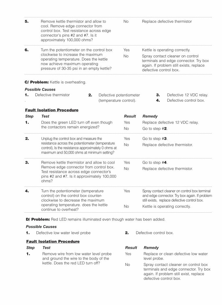
5. Remove kettle thermistor and allow tocool. Remove edge connector fromcontrol box. Test resistance across edgeconnector's pins #2 and #7. Is itapproximately 100,000 ohms?
6. Turn the potentiometer on the control boxclockwise to increase the maximumoperating temperature. Does the kettlenow achieve maximum operatingpressure of 30-35 psi in an empty kettle?
No Replace defective thermistor
Yes Kettle is operating correctly.
No Spray contact cleaner on controlterminals and edge connector. Try boxagain. If problem still exists, replacedefective control box.
Fault Isolation Procedure
Step Test1. Does the green LED turn off even though
the contactors remain energized?
2. Unplug the control box and measure theresistance across the potentiometer (temperaturecontrol), Is the resistance approximately 0 ohms atmaximum and 50,000 ohms at minimum setting?
3. Remove kettle thermistor and allow to coolRemove edge connector from control box.Test resistance across edge connector’spins #2 and #7. Is it approximately 100,000ohms?
4. Turn the potentiometer (temperaturecontrol) on the control box counter-clockwise to decrease the maximumoperating temperature. does the kettlecontinue to overheat?
Result RemedyYes Replace defective 12 VDC relay.
No Go to step #2.
Yes Go to step #3.
No Replace defective thermistor.
Yes Go to step #4.
No Replace defective thermistor.
Yes Spray contact cleaner on control box terminaland edge connector. Try box again. If problemstill exists, replace defective control box.
No Kettle is operating correctly.
Possible Causes1. Defective thermistor.
2. Defective potentiometer(temperature control).
3. Defective 12 VDC relay.4. Defective control box.
C/ Problem: Kettle is overheating.
Fault Isolation Procedure
Step Test1. Remove wire from low water level probe
and ground the wire to the body of thekettle. Does the red LED turn off?
Result RemedyYes Replace or clean defective low water
level probe.
No Spray contact cleaner on control boxterminals and edge connector. Try boxagain. If problem still exist, replacedefective control box.
Possible Causes1. Defective low water level probe 2. Defective control box.
D/ Problem: Red LED remains illuminated even though water has been added.

WIRING DIAGRAM3 Gallon Kettles200-240vSingle Phase Only
380-480vSingle Phase Only

WIRING DIAGRAM6-20 Gallon200-240v
380-600v