Embed Size (px)
Citation preview

1. General description
The SE95 is a temperature-to-digital converter using an on-chip band gap temperaturesensor and Sigma Delta analog-to-digital conversion technique. The device is also athermal detector providing an overtemperature detection output.
The SE95 contains a number of data registers accessed by a controller via the 2-wireserial I2C-bus interface:
• Configuration register (Conf) to store the device settings such as sampling rate,device operation mode, OS operation mode, OS polarity, and OS fault queue
• Temperature register (Temp) to store the digital Temp reading
• Set-point registers (Tos and Thyst) to store programmable overtemperature shutdownand hysteresis limits
• Identification register (ID) to store manufacturer numbers
The device includes an open-drain output (pin OS) which becomes active when thetemperature exceeds the programmed limits. There are three selectable logic addresspins (pins A2 to A0) so that eight devices can be connected on the same bus withoutaddress conflict.
The SE95 can be configured for different operation conditions. It can be set in normalmode to periodically monitor the ambient temperature, or in shutdown mode to minimizepower consumption. The OS output operates in either of two selectable modes: OScomparator mode and OS interrupt mode. Its active state can be selected as either HIGHor LOW. The fault queue that defines the number of consecutive faults in order to activatethe OS output is programmable as well as the set-point limits.
The temperature register always stores a 13-bit two’s complement data giving atemperature resolution of 0.03125 °C. This high temperature resolution is particularlyuseful in applications of measuring precisely the thermal drift or runaway. For normaloperation and compatibility with the LM75A, only the 11 MSBs are read, with a resolutionof 0.125 °C to provide the accuracies specified. To be compatible with the LM75, read onlythe 9 MSBs.
The device is powered-up in normal operation mode with the OS in comparator mode,temperature threshold of 80 °C and hysteresis of 75 °C, so that it can be used as astand-alone thermostat with those pre-defined temperature set points. The conversionrate is programmable, with a default of 10 conversions/s.
SE95Ultra high accuracy digital temperature sensor and thermalwatchdogRev. 07 — 2 September 2009 Product data sheet

NXP Semiconductors SE95Ultra high accuracy digital temperature sensor and thermal watchdog
2. Features
n Pin-for-pin replacement for industry standard LM75/LM75A
n Specification of a single part over supply voltage from 2.8 V to 5.5 V
n Small 8-pin package types: SO8 and TSSOP8 (MSOP8)
n I2C-bus interface to 400 kHz with up to 8 devices on the same bus
n Supply voltage from 2.8 V to 5.5 V
n Temperature range from −55 °C to +125 °Cn 13-bit ADC that offers a temperature resolution of 0.03125 °Cn Temperature accuracy of ± 1 °C from −25 °C to +100 °Cn Programmable temperature threshold and hysteresis set points
n Supply current of 7.0 µA in shutdown mode for power conservation
n Stand-alone operation as thermostat at power-up
n ESD protection exceeds 1000 V for Human Body Model (HBM) per JESD22-A114 and150 V for Machine Model (MM) per JESD22-A115
n Latch-up testing is done to JEDEC Standard JESD78 which exceeds 100 mA
3. Applications
n System thermal management
n Personal computers
n Electronics equipment
n Industrial controllers
4. Ordering information
Table 1. Ordering information
Typenumber
Package
Temperature range Name Description Version
SE95D −55 °C to +125 °C SO8 plastic small outline package; 8 leads; body width 3.9 mm SOT96-1
SE95DP −55 °C to +125 °C TSSOP8 plastic thin shrink small outline package; 8 leads;body width 3 mm
SOT505-1
SE95U −55 °C to +125 °C - wafer -
SE95_7 © NXP B.V. 2009. All rights reserved.
Product data sheet Rev. 07 — 2 September 2009 2 of 27

NXP Semiconductors SE95Ultra high accuracy digital temperature sensor and thermal watchdog
5. Block diagram
6. Pinning information
6.1 Pinning
6.2 Pin description
Fig 1. Block diagram of SE95
002aae892A2 A1 A0 SCL SDA GND
OS3
5 6 7 2 1 4
8VCC
SE95ADC CONTROL AND OTP CONTROL
I2C-BUS INTERFACE LOGIC
OTP
BIAS
SIGMA DELTAMODULATOR
INTERRUPTIONLOGIC
DECIMATIONFILTER
BAND GAP
OSCILLATOR
POR
bitstream
REGISTERBANK
Conf
Temp
Tos
Thyst
Fig 2. Pin configuration for SO8 Fig 3. Pin configuration for TSSOP8
SE95D
SDA VCC
SCL A0
OS A1
GND A2
002aac537
1
2
3
4
6
5
8
7
SE95DP
002aac536
1
2
3
4
6
5
8
7
SDA VCC
SCL A0
OS A1
GND A2
Table 2. Pin description
Symbol Pin Description
SDA 1 I2C-bus serial bidirectional data line digital I/O; open-drain
SCL 2 I2C-bus serial clock digital input
OS 3 overtemperature shutdown output; open-drain
GND 4 ground; to be connected to the system ground
A2 5 user-defined address bit 2 digital input
SE95_7 © NXP B.V. 2009. All rights reserved.
Product data sheet Rev. 07 — 2 September 2009 3 of 27
NXP Semiconductors SE95Ultra high accuracy digital temperature sensor and thermal watchdog
7. Functional description
7.1 General operationThe SE95 uses the on-chip band gap sensor to measure the device temperature with aresolution of 0.03125 °C and stores the 13-bit two’s complement digital data, resultingfrom 13-bit analog to digital conversion, into register Temp. Register Temp can be read atany time by a controller on the I2C-bus. Reading temperature data does not affect theconversion in progress during the read operation.
The device can be set to operate in either mode: normal or shutdown mode. In normaloperation mode, by default, the temperature-to-digital conversion is executed every100 ms and register Temp is updated at the end of each conversion. In shutdown mode,the device becomes idle, data conversion is disabled and register Temp holds the latestresult; however, the device I2C-bus interface is still active and register write/read operationcan be performed. The device operation mode is controlled by programming bitSHUTDOWN of register Conf. The temperature conversion is initiated when the device ispowered up or returned to normal mode from shutdown mode.
In addition, at the end of each conversion in normal mode, the temperature data (or Temp)in register Temp is automatically compared with the overtemperature shutdown thresholddata (or Tos) stored in register Tos, and the hysteresis data (or Thyst) stored in registerThyst, in order to set the state of the device OS output accordingly. The registers Tos andThyst are write/read capable, and both operate with 9-bit two’s complement digital data.To match with this 9-bit operation, register Temp uses only the 9 MSB bits of its 13-bit datafor the comparison.
The device temperature conversion rate is programmable and can be chosen to be one ofthe four values: 0.125, 1.0, 10, and 30 conversions/s. The default conversion rate is10 conversions/s. Furthermore, the conversion rate is selected by programming bitsRATEVAL[1:0] of register Conf as shown in Table 6. Note that the average supply currentas well as the device power consumption increase with the conversion rate.
The way that the OS output responds to the comparison operation depends upon the OSoperation mode selected by configuration bit OS_COMP_INT, and the user-defined faultqueue defined by configuration bits OS_F_QUE[1:0].
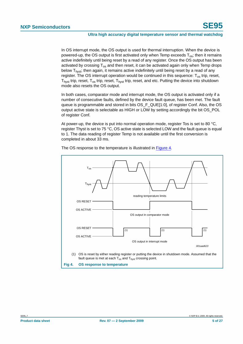
In OS comparator mode, the OS output behaves like a thermostat. It becomes activewhen the temperature exceeds Tos, and is reset when the temperature drops below Thyst.Reading the device registers or putting the device into shutdown mode does not changethe state of the OS output. The OS output in this case can be used to control cooling fansor thermal switches.
A1 6 user-defined address bit 1 digital input
A0 7 user-defined address bit 0 digital input
VCC 8 supply voltage
Table 2. Pin description …continued
Symbol Pin Description
SE95_7 © NXP B.V. 2009. All rights reserved.
Product data sheet Rev. 07 — 2 September 2009 4 of 27
NXP Semiconductors SE95Ultra high accuracy digital temperature sensor and thermal watchdog
In OS interrupt mode, the OS output is used for thermal interruption. When the device ispowered-up, the OS output is first activated only when Temp exceeds Tos; then it remainsactive indefinitely until being reset by a read of any register. Once the OS output has beenactivated by crossing Tos and then reset, it can be activated again only when Temp dropsbelow Thyst; then again, it remains active indefinitely until being reset by a read of anyregister. The OS interrupt operation would be continued in this sequence: Tos trip, reset,Thyst trip, reset, Tos trip, reset, Thyst trip, reset, and etc. Putting the device into shutdownmode also resets the OS output.
In both cases, comparator mode and interrupt mode, the OS output is activated only if anumber of consecutive faults, defined by the device fault queue, has been met. The faultqueue is programmable and stored in bits OS_F_QUE[1:0], of register Conf. Also, the OSoutput active state is selectable as HIGH or LOW by setting accordingly the bit OS_POLof register Conf.
At power-up, the device is put into normal operation mode, register Tos is set to 80 °C,register Thyst is set to 75 °C, OS active state is selected LOW and the fault queue is equalto 1. The data reading of register Temp is not available until the first conversion iscompleted in about 33 ms.
The OS response to the temperature is illustrated in Figure 4.
(1) OS is reset by either reading register or putting the device in shutdown mode. Assumed that thefault queue is met at each Tos and Thyst crossing point.
Fig 4. OS response to temperature
001aad623
(1) (1) (1)
Tos
Thyst
OS RESET
OS ACTIVE
OS RESET
OS ACTIVE
OS output in comparator mode
OS output in interrupt mode
reading temperature limits
SE95_7 © NXP B.V. 2009. All rights reserved.
Product data sheet Rev. 07 — 2 September 2009 5 of 27

NXP Semiconductors SE95Ultra high accuracy digital temperature sensor and thermal watchdog
7.2 OS output and polarityThe OS output is an open-drain output and its state represents results of the devicewatchdog operation as described in Section 7.1. In order to observe this output state, anexternal pull-up resistor is needed. The resistor should be as large as possible, up to200 kΩ, to minimize the Temp reading error due to internal heating by the high OS sinkingcurrent.
The OS output active state can be selected as HIGH or LOW by programming bitOS_POL of register Conf: setting bit OS_POL to logic 1 selects OS active HIGH andsetting to logic 0 sets OS active LOW. At power-up, bit OS_POL is equal to logic 0 and theOS active state is LOW.
7.3 OS comparator and interrupt modesAs described in Section 7.1, the OS output responds to the result of the comparisonbetween register Temp data and the programmed limits, in registers Tos and Thyst, indifferent ways depending on the selected OS mode: OS comparator or OS interrupt. TheOS mode is selected by programming bit OS_COMP_INT of register Conf: setting bitOS_COMP_INT to logic 1 selects the OS interrupt mode, and setting to logic 0 selects theOS comparator mode. At power-up, bit OS_COMP_INT is equal to logic 0 and the OScomparator is selected.
The main difference between the two modes is that in OS comparator mode, the OSoutput becomes active when Temp has exceeded Tos and reset when Temp has droppedbelow Thyst, reading a register or putting the device into shutdown mode does not changethe state of the OS output; while in OS interrupt mode, once it has been activated eitherby exceeding Tos or dropping below Thyst, the OS output will remain active indefinitely untilreading a register or putting the device into shutdown mode occurs, then the OS output isreset.
Temperature limits Tos and Thyst must be selected so that Tos > Thyst. Otherwise, the OSoutput state will be undefined.
7.4 OS fault queueFault queue is defined as the number of faults that must occur consecutively to activatethe OS output. It is provided to avoid false tripping due to noise. Because faults aredetermined at the end of data conversions, fault queue is also defined as the number ofconsecutive conversions returning a temperature trip. The value of fault queue isselectable by programming the two bits OS_F_QUE[1:0] in register Conf. Notice that theprogrammed data and the fault queue value are not the same. Table 3 shows theone-to-one relationship between them. At power-up, fault queue data = 00 and fault queuevalue = 1.
Table 3. Fault queue table
Fault queue data Fault queue value
OS_F_QUE[1] OS_F_QUE[0] Decimal
0 0 1
0 1 2
1 0 4
1 1 6
SE95_7 © NXP B.V. 2009. All rights reserved.
Product data sheet Rev. 07 — 2 September 2009 6 of 27

NXP Semiconductors SE95Ultra high accuracy digital temperature sensor and thermal watchdog
7.5 Shutdown modeThe device operation mode is selected by programming bit SHUTDOWN of register Conf.Setting bit SHUTDOWN to logic 1 will put the device into shutdown mode. Resetting bitSHUTDOWN to logic 0 will return the device to normal mode.
In shutdown mode, the device draws a small current of approximately 7.5 µA and thepower dissipation is minimized; the temperature conversion stops, but the I2C-businterface remains active and register write/read operation can be performed. If the OSoutput is in comparator mode, then it remains unchanged. In interrupt mode, the OSoutput is reset.
7.6 Power-up default and power-on resetThe SE95 always powers-up in its default state with:
• Normal operation mode
• OS comparator mode
• Tos = 80 °C
• Thyst = 75 °C
• OS output active state is LOW
• Pointer value is logic 0
When the power supply voltage is dropped below the device power-on reset level ofapproximately 1.9 V (POR) and then rises up again, the device will be reset to its defaultcondition as listed above.
8. I2C-bus serial interface
The SE95 can be connected to a compatible 2-wire serial interface I2C-bus as a slavedevice under the control of a controller or master device, using two device terminals, SCLand SDA. The controller must provide the SCL clock signal and write/read data to andfrom the device through the SDA terminal. Note that if the I2C-bus common pull-upresistors have not been installed as required for I2C-bus, then an external pull-up resistor,approximately 10 kΩ, is needed for each of these two terminals. The bus communicationprotocols are described in Section 8.7 “Protocols for writing and reading the registers”.
8.1 Slave addressThe SE95 slave address on the I2C-bus is partially defined by the logic applied to thedevice address pins A2, A1 and A0. Each pin is typically connected either to GND forlogic 0, or to VCC for logic 1. These pins represent the three LSB bits of the device 7-bitaddress. The other four MSB bits of the address data are preset to 1001 by hard wiringinside the SE95. Table 4 shows the device's complete address and indicates that up to8 devices can be connected to the same bus without address conflict. Because the inputpins SCL, SDA and A2 to A0, are not internally biased, it is important that they should notbe left floating in any application.
0Ch is a reserved address for SMBus Alert Response Address (ARA). This is an optionalcommand from the SMBus specification to allow SMBus devices to respond to an SMBusmaster with their slave device if they are generating an interrupt. The SE95 will send a
SE95_7 © NXP B.V. 2009. All rights reserved.
Product data sheet Rev. 07 — 2 September 2009 7 of 27
NXP Semiconductors SE95Ultra high accuracy digital temperature sensor and thermal watchdog
false alert if the address 0Ch is sent and cannot be active on the I2C-bus if this address isused. Consider using the SE98 since it supports SMBus ARA as well as time-out featuresand provides ±1 °C accuracy.
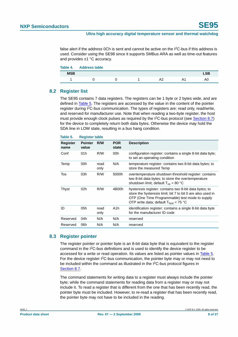
8.2 Register listThe SE95 contains 7 data registers. The registers can be 1 byte or 2 bytes wide, and aredefined in Table 5. The registers are accessed by the value in the content of the pointerregister during I2C-bus communication. The types of registers are: read only, read/write,and reserved for manufacturer use. Note that when reading a two-byte register, the hostmust provide enough clock pulses as required by the I2C-bus protocol (see Section 8.7)for the device to completely return both data bytes. Otherwise the device may hold theSDA line in LOW state, resulting in a bus hang condition.
8.3 Register pointerThe register pointer or pointer byte is an 8-bit data byte that is equivalent to the registercommand in the I2C-bus definitions and is used to identify the device register to beaccessed for a write or read operation. Its values are listed as pointer values in Table 5.For the device register I2C-bus communication, the pointer byte may or may not need tobe included within the command as illustrated in the I2C-bus protocol figures inSection 8.7.
The command statements for writing data to a register must always include the pointerbyte; while the command statements for reading data from a register may or may notinclude it. To read a register that is different from the one that has been recently read, thepointer byte must be included. However, to re-read a register that has been recently read,the pointer byte may not have to be included in the reading.
Table 4. Address table
MSB LSB
1 0 0 1 A2 A1 A0
Table 5. Register table
Registername
Pointervalue
R/W PORstate
Description
Conf 01h R/W 00h configuration register: contains a single 8-bit data byte;to set an operating condition
Temp 00h readonly
N/A temperature register: contains two 8-bit data bytes; tostore the measured Temp
Tos 03h R/W 5000h overtemperature shutdown threshold register: containstwo 8-bit data bytes; to store the overtemperatureshutdown limit; default Tos = 80 °C
Thyst 02h R/W 4B00h hysteresis register: contains two 8-bit data bytes; tostore the hysteresis limit; bit 7 to bit 0 are also used inOTP (One Time Programmable) test mode to supplyOTP write data; default Thyst = 75 °C
ID 05h readonly
A1h identification register: contains a single 8-bit data bytefor the manufacturer ID code
Reserved 04h N/A N/A reserved
Reserved 06h N/A N/A reserved
SE95_7 © NXP B.V. 2009. All rights reserved.
Product data sheet Rev. 07 — 2 September 2009 8 of 27

NXP Semiconductors SE95Ultra high accuracy digital temperature sensor and thermal watchdog
At power-up, the pointer value is preset to logic 0 for register Temp; users can then readthe temperature without specifying the pointer byte.
8.4 Configuration registerThe Configuration (Conf) register is a read/write register and contains an 8-bitnon-complement data byte that is used to configure the device for different operatingconditions. Table 6 shows the bit assignments of this register.
8.5 Temperature registerThe Temperature (Temp) register holds the digital result of temperature measurement ormonitor at the end of each analog to digital conversion. This register is read only andcontains two 8-bit data bytes consisting of one Most Significant Byte (MSByte) and oneLeast Significant Byte (LSByte). However, only 13 bits of those two bytes are used to storethe Temp data in two’s complement format with the resolution of 0.03125 °C. Table 7shows the bit arrangement of the Temp data in the data bytes.
Table 6. Conf registerLegend: * = default value.
Bit Symbol Access Value Description
7 reserved R/W 0* reserved for manufacturer’s use
6 and 5 RATEVAL[1:0] R/W sets the conversion rate
00* 10 conversion/s
01 0.125 conversion/s
10 1 conversion/s
11 30 conversion/s
4 and 3 OS_F_QUE[1:0] R/W OS fault queue programming
00* queue value = 1
01 queue value = 2
10 queue value = 4
11 queue value = 6
2 OS_POL R/W OS polarity selection
0* OS active LOW
1 OS active HIGH
1 OS_COMP_INT R/W OS operation mode selection
0* OS comparator
1 OS interrupt
0 SHUTDOWN R/W 0 operation mode
0* normal
1 shutdown
Table 7. Temp register
MSByte LSByte
7 6 5 4 3 2 1 0 7 6 5 4 3 2 1 0
D15 D14 D13 D12 D11 D10 D9 D8 D7 D6 D5 D4 D3 D2 D1 D0
SE95_7 © NXP B.V. 2009. All rights reserved.
Product data sheet Rev. 07 — 2 September 2009 9 of 27

NXP Semiconductors SE95Ultra high accuracy digital temperature sensor and thermal watchdog
When reading register Temp, all 16 bits of the two data bytes (MSByte and LSByte) mustbe collected and then the two’s complement data value according to the desired resolutionmust be selected for the temperature calculation. Table 8 shows the example for 11-bittwo’s complement data value, Table 9 shows the example for 13-bit two’s complementdata value.
When converting into the temperature the proper resolution must be used as listed inTable 10 using either one of these two formulae:
1. If the Temp data MSB = 0, then: Temp (°C) = +(Temp data) × value resolution
2. If the Temp data MSB = 1, then: Temp (°C) = −(two’s complement Temp data) × valueresolution
Table 11 shows some examples of the results for the 11-bit calculations.
Table 8. Example 11-bit two’s complement Temp register
MSByte LSByte
7 6 5 4 3 2 1 0 7 6 5 4 3 2 1 0
D10 D9 D8 D7 D6 D5 D4 D3 D2 D1 D0 X X X X X
Table 9. Example 13-bit two’s complement register
MSByte LSByte
7 6 5 4 3 2 1 0 7 6 5 4 3 2 1 0
D12 D11 D10 D9 D8 D7 D6 D5 D4 D3 D2 D1 D0 X X X
Table 10. Temp data and Temp value resolution
Data resolution Value resolution
8 bit 1.0 °C
9 bit 0.5 °C
10 bit 0.25 °C
11 bit 0.125 °C
12 bit 0.0625 °C
13 bit 0.03125 °C
Table 11. Temp register value
11-bit binary(two’s complement)
Hexadecimal value Decimal value Value
011 1111 1000 3F8 1016 +127.000 °C
011 1111 0111 3F7 1015 +126.875 °C
011 1111 0001 3F1 1009 +126.125 °C
011 1110 1000 3E8 1000 +125.000 °C
000 1100 1000 0C8 200 +25.000 °C
000 0000 0001 001 1 +0.125 °C
000 0000 0000 000 0 0.000 °C
111 1111 1111 7FF −1 −0.125 °C
111 0011 1000 738 −200 −25.000 °C
110 0100 1001 649 −439 −54.875 °C
110 0100 1000 648 −440 −55.000 °C
SE95_7 © NXP B.V. 2009. All rights reserved.
Product data sheet Rev. 07 — 2 September 2009 10 of 27

NXP Semiconductors SE95Ultra high accuracy digital temperature sensor and thermal watchdog
Obviously, for 9-bit Temp data application in replacing the industry standard LM75, justuse only 9 MSB bits of the two bytes and disregard 7 LSB of the LSByte. The 9-bit Tempdata with 0.5 °C resolution of the SE95 is defined exactly in the same way as for thestandard LM75 and it is here similar to the Tos and Thyst registers.
8.6 Overtemperature shutdown threshold and hysteresis registersThese two registers, are write/read registers, and also called set-point registers. They areused to store the user-defined temperature limits, called overtemperature shutdownthreshold (Tos) and hysteresis temperature (Thyst), for the device watchdog operation. Atthe end of each conversion the Temp data will be compared with the data stored in thesetwo registers in order to set the state of the device OS output; see Section 7.1.
Each of the set-point registers contains two 8-bit data bytes consisting of one MSByte andone LSByte the same as register Temp. However, only 9 bits of the two bytes are used tostore the set-point data in two’s complement format with the resolution of 0.5 °C. Table 12and Table 13 show the bit arrangement of the Tos data and Thyst data in the data bytes.
Notice that because only 9-bit data are used in the set-point registers, the device usesonly the 9 MSB of the Temp data for data comparison.
When a set-point register is read, all 16 bits are provided to the bus and must be collectedby the controller to complete the bus operation. However, only the 9 most significant bitsshould be used and the 7 LSB of the LSByte are equal to zero and should be ignored.
Table 14 shows examples of the limit data and value.
Table 12. Tos register
MSByte LSByte
7 6 5 4 3 2 1 0 7 6 5 4 3 2 1 0
D8 D7 D6 D5 D4 D3 D2 D1 D0 X X X X X X X
Table 13. Thyst register
MSByte LSByte
7 6 5 4 3 2 1 0 7 6 5 4 3 2 1 0
D8 D7 D6 D5 D4 D3 D2 D1 D0 X X X X X X X
Table 14. Tos and Thyst register
11-bit binary(two’s complement)
Hexadecimal value Decimal value Value
0 1111 1010 0FA 250 125.0 °C
0 0011 0010 032 50 25.0 °C
0 0000 0001 001 1 0.5 °C
0 0000 0000 000 0 0.0 °C
1 1111 1111 1FF −1 −0.5 °C
1 1100 1110 1CE −50 −25.0 °C
1 1001 0010 192 −110 −55.0 °C
SE95_7 © NXP B.V. 2009. All rights reserved.
Product data sheet Rev. 07 — 2 September 2009 11 of 27

NXP Semiconductors SE95Ultra high accuracy digital temperature sensor and thermal watchdog
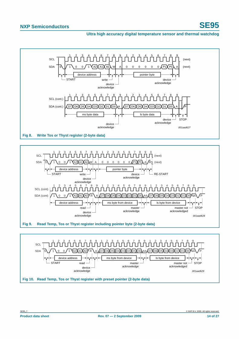
8.7 Protocols for writing and reading the registersThe communication between the host and the SE95 must follow the rules strictly asdefined by the I2C-bus management. The protocols for SE95 register read/writeoperations are illustrated in Figure 5 to Figure 10 together with the following definitions:
1. Before a communication, the I2C-bus must be free or not busy. It means that the SCLand SDA lines must both be released by all devices on the bus, and they becomeHIGH by the bus pull-up resistors.
2. The host must provide SCL clock pulses necessary for the communication. Data istransferred in a sequence of 9 SCL clock pulses for every 8-bit data byte followed by1-bit status of the acknowledgement.
3. During data transfer, except the START and STOP signals, the SDA signal must bestable while the SCL signal is HIGH. It means that the SDA signal can be changedonly during the LOW duration of the SCL line.
4. S: START signal, initiated by the host to start a communication, the SDA goes fromHIGH-to-LOW while the SCL is HIGH.
5. RS: RE-START signal, same as the START signal, to start a read command thatfollows a write command.
6. P: STOP signal, generated by the host to stop a communication, the SDA goes fromLOW-to-HIGH while the SCL is HIGH. The bus becomes free thereafter.
7. W: write bit, when the write/read bit is in a write command.
8. R: read bit, when the write/read bit is logic 1 in a read command.
9. A: device acknowledge bit, returned by the SE95. It is logic 0 if the device worksproperly and logic 1 if not. The host must release the SDA line during this period inorder to give the device the control on the SDA line.
10. A’: master acknowledge bit, not returned by the device, but set by the master or hostin reading 2-byte data. During this clock period, the host must set the SDA line toLOW in order to notify the device that the first byte has been read for the device toprovide the second byte onto the bus.
11. NA: not-acknowledge bit. During this clock period, both the device and host releasethe SDA line at the end of a data transfer, the host is then enabled to generate thestop signal.
12. In a write protocol, data is sent from the host to the device and the host controls theSDA line, except during the clock period when the device sends the deviceacknowledgement signal to the bus.
13. In a read protocol, data is sent to the bus by the device and the host must release theSDA line during the time that the device is providing data onto the bus and controllingthe SDA line, except during the clock period when the master sends the masteracknowledgement signal to the bus.
SE95_7 © NXP B.V. 2009. All rights reserved.
Product data sheet Rev. 07 — 2 September 2009 12 of 27

NXP Semiconductors SE95Ultra high accuracy digital temperature sensor and thermal watchdog
Fig 5. Write configuration register (1-byte data)
001aad624
1
1SSDA
SCL
0 0 1 A2 A1 A0 W A 0 0 0 0 0 0 0 1 A 0 0 0 D4 D3 D2 D1 D0 A P
2 3 4 5 6 7 8 9 1 2 3 4 5 6 7 8 9 1 2 3 4 5 6 7 8 9
START STOPwrite deviceacknowledge
deviceacknowledgedevice
acknowledge
device address pointer byte configuration data byte
Fig 6. Read configuration register including pointer byte (1-byte data)
001aad625
SCL
SDA
(next)
(next)
1 2 3 4 5 6 7 8 9 1 2 3 4 5 6 7 8 9
device address pointer byte
START RE-STARTwrite deviceacknowledgedevice
acknowledge
0 0 0 0 0 0 0 1 A RS1S 0 0 1 A2 A1 A0 W A
SCL (cont.)
SDA (cont.)
1 2 3 4 5 6 7 8 9 1 2 3 4 5 6 7 8 9
device address data byte from device
STOPread master notacknowledgeddevice
acknowledge
D7 D6 D5 D4 D3 D2 D1 D0 P1 0 0 1 A2 A1 A0 R A NA
Fig 7. Read configuration register with preset pointer (1-byte data)
001aad626
START
S
SCL
SDA
1 2 3 4 5 6 7 8 9 1 2 3 4 5 6 7 8 9
device address data byte from device
STOPread master notacknowledgeddevice
acknowledge
D7 D6 D5 D4 D3 D2 D1 D0 P1 0 0 1 A2 A1 A0 R A NA
SE95_7 © NXP B.V. 2009. All rights reserved.
Product data sheet Rev. 07 — 2 September 2009 13 of 27
NXP Semiconductors SE95Ultra high accuracy digital temperature sensor and thermal watchdog
Fig 8. Write Tos or Thyst register (2-byte data)
001aad627
1 2 3 4 5 6 7 8 9 1 2 3 4 5 6 7 8 9
D7SDA (cont.)
SCL (cont.)
D6 D5 D4 D3 D2 D1 D0 A D7 D6 D5 D4 D3 D2 D1 D0 A P
1SSDA
SCL
0 0 1 A2 A1 A0 W A 0 0 0 0 0 0 P1 P0 A (next)
(next)
1 2 3 4 5 6 7 8 9 1 2 3 4 5 6 7 8 9
device address pointer byte
ms byte data ls byte data
START write deviceacknowledgedevice
acknowledge
STOPdeviceacknowledgedevice
acknowledge
Fig 9. Read Temp, Tos or Thyst register including pointer byte (2-byte data)
1 2 3 4 5 6 7 8 9
1 2 3 4 5 6 7 8 9 1 2 3 4 5 6 7 8 9 1 2 3 4 5 6 7 8 9
1 0 0 1 A2 A1 A0 R A D7 D6 D5 D4 D3 D2 D1 D0 A4 D7 D6 D5 D4 D3 D2 D1 D0 NA P
1 2 3 4 5 6 7 8 9 0
1S 0 0 1 A2 A1 A0 W A 0 0 0 0 0 0 P1 P0 A (next)
(next)
SDA
SCL
SDA (cont)
SCL (cont)
RS
001aad628
device address pointer byte
device address ms byte from device ls byte from device
START RE-STARTwrite deviceacknowledgedevice
acknowledge
read masteracknowledge
master not acknowledgeddevice
acknowledge
STOP
Fig 10. Read Temp, Tos or Thyst register with preset pointer (2-byte data)
1 2 3 4 5 6 7 8 9 1 2 3 4 5 6 7 8 9 1 2 3 4 5 6 7 8 9
1S 0 0 1 A2 A1 A0 R A D7 D6 D5 D4 D3 D2 D1 D0 A4 D7 D6 D5 D4 D3 D2 D1 D0 NA PSDA
SCL
001aad629
device address ms byte from device ls byte from device
START read masteracknowledge
master notacknowledgeddevice
acknowledge
STOP
SE95_7 © NXP B.V. 2009. All rights reserved.
Product data sheet Rev. 07 — 2 September 2009 14 of 27

NXP Semiconductors SE95Ultra high accuracy digital temperature sensor and thermal watchdog
9. Limiting values
10. Recommended operating conditions
Table 15. Limiting valuesIn accordance with the Absolute Maximum Rating System (IEC 60134).
Symbol Parameter Conditions Min Max Unit
VCC supply voltage −0.3 +6.0 V
VI(SCL) input voltage on pin SCL −0.3 +6.0 V
VI(SDA) input voltage on pin SDA −0.3 +6.0 V
VI(A0) input voltage on pin A0 −3.0 VCC + 0.3 V
VI(A1) input voltage on pin A1 −3.0 VCC + 0.3 V
VI(A2) input voltage on pin A2 −3.0 VCC + 0.3 V
II(PIN) input current on input pins −5.0 +5.0 mA
IO(OS) output current on pin OS - 10.0 mA
VO(OS) output voltage on pin OS −0.3 +6.0 V
VESD electrostatic dischargevoltage
human body model - 1000 V
machine model - 150 V
Tstg storage temperature −65 +150 °C
Tj junction temperature - 150 °C
Table 16. Recommended operating characteristics
Symbol Parameter Conditions Min Typ Max Unit
VCC supply voltage 2.8 - 5.5 V
Tamb ambient temperature −55 - +125 °C
SE95_7 © NXP B.V. 2009. All rights reserved.
Product data sheet Rev. 07 — 2 September 2009 15 of 27

NXP Semiconductors SE95Ultra high accuracy digital temperature sensor and thermal watchdog
11. Static characteristics
[1] Typical values are at VCC = 3.3 V and Tamb = 25 °C.
[2] Assumes a minimum 11-bit temperature reading.
[3] The digital pins are pin SCL, SDA and A2 to A0.
[4] Device analog-to-digital conversion.
Table 17. Static characteristicsVCC = 2.8 V to 5.5 V, Tamb = −55 °C to +125 °C; unless otherwise specified.
Symbol Parameter Conditions Min Typ[1] Max Unit
Tacc temperature accuracy VCC = 2.8 V to 3.6 V [2]
Tamb = −25 °C to +100 °C −1.0 - +1.0 °C
Tamb = −55 °C to +125 °C −2.0 - +2.0 °C
VCC = 3.6 V to 5.5 V [2]
Tamb = −25 °C to +100 °C −2 - +2 °C
Tamb = −55 °C to +125 °C −3 - +3 °C
Tres temperature resolution 11-bit digital temperature data - 0.125 - °C
tconv(T) temperature conversion time normal mode - 33 - ms
ICC supply current normal mode: I2C-bus inactive - 150 - µA
normal mode: I2C-bus active - - 1.0 mA
shutdown mode - 7.5 - µA
VIH HIGH-level input voltage digital pins [3] 0.7VCC - VCC + 0.3 V
VIL LOW-level input voltage digital pins [3] −0.3 - +0.3VCC V
VI(hys) hysteresis of input voltage pins SCL and SDA - 300 - mV
pins A2 to A0 - 300 - mV
IIH HIGH-level input current digital pins; VIN = VCC[3] −1.0 - +1.0 µA
IIL LOW-level input current digital pins; VIN = 0 V [3] −1.0 - +1.0 µA
VOL LOW-level output voltage pins SDA and OS; IOL = 3 mA - - 0.4 V
IOL = 4 mA - - 0.8 V
ILO output leakage current pins SDA and OS; VOH = VCC - - 10 µA
VPOR power-on reset voltage VCC supply below which thelogic is reset
1.0 - 2.5 V
OSQ OS fault queue programmable [4] 1 - 6
Tos overtemperature shutdownthreshold
default value - 80 - °C
fsam sampling rate programmable 0.125 10 30 sample/s
Thyst hysteresis temperature default value - 75 - °C
Ci input capacitance digital pins - 20 - pF
SE95_7 © NXP B.V. 2009. All rights reserved.
Product data sheet Rev. 07 — 2 September 2009 16 of 27
NXP Semiconductors SE95Ultra high accuracy digital temperature sensor and thermal watchdog
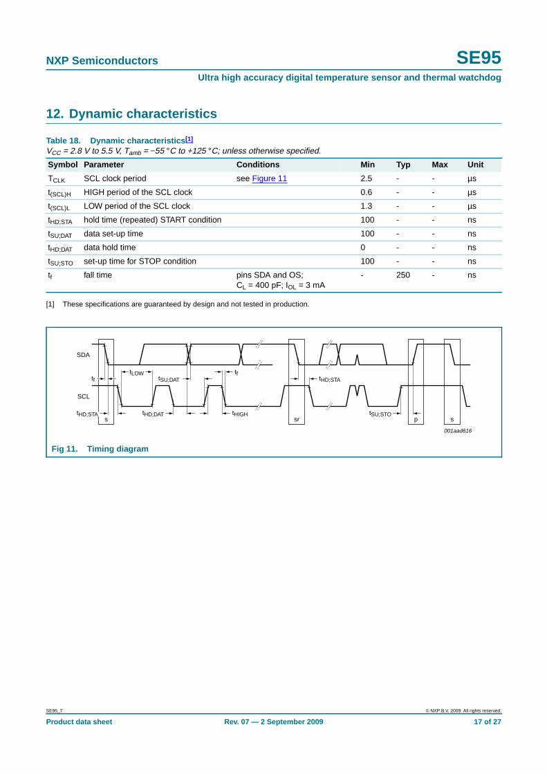
12. Dynamic characteristics
[1] These specifications are guaranteed by design and not tested in production.
Table 18. Dynamic characteristics [1]
VCC = 2.8 V to 5.5 V, Tamb = −55 °C to +125 °C; unless otherwise specified.
Symbol Parameter Conditions Min Typ Max Unit
TCLK SCL clock period see Figure 11 2.5 - - µs
t(SCL)H HIGH period of the SCL clock 0.6 - - µs
t(SCL)L LOW period of the SCL clock 1.3 - - µs
tHD;STA hold time (repeated) START condition 100 - - ns
tSU;DAT data set-up time 100 - - ns
tHD;DAT data hold time 0 - - ns
tSU;STO set-up time for STOP condition 100 - - ns
tf fall time pins SDA and OS;CL = 400 pF; IOL = 3 mA
- 250 - ns
Fig 11. Timing diagram
001aad616
SDA
SCL
tHIGH
tLOW
s sr p s
tftHD;STA
tHD;DAT
tf tSU;DAT
tSU;STOtHD;STA
SE95_7 © NXP B.V. 2009. All rights reserved.
Product data sheet Rev. 07 — 2 September 2009 17 of 27
NXP Semiconductors SE95Ultra high accuracy digital temperature sensor and thermal watchdog
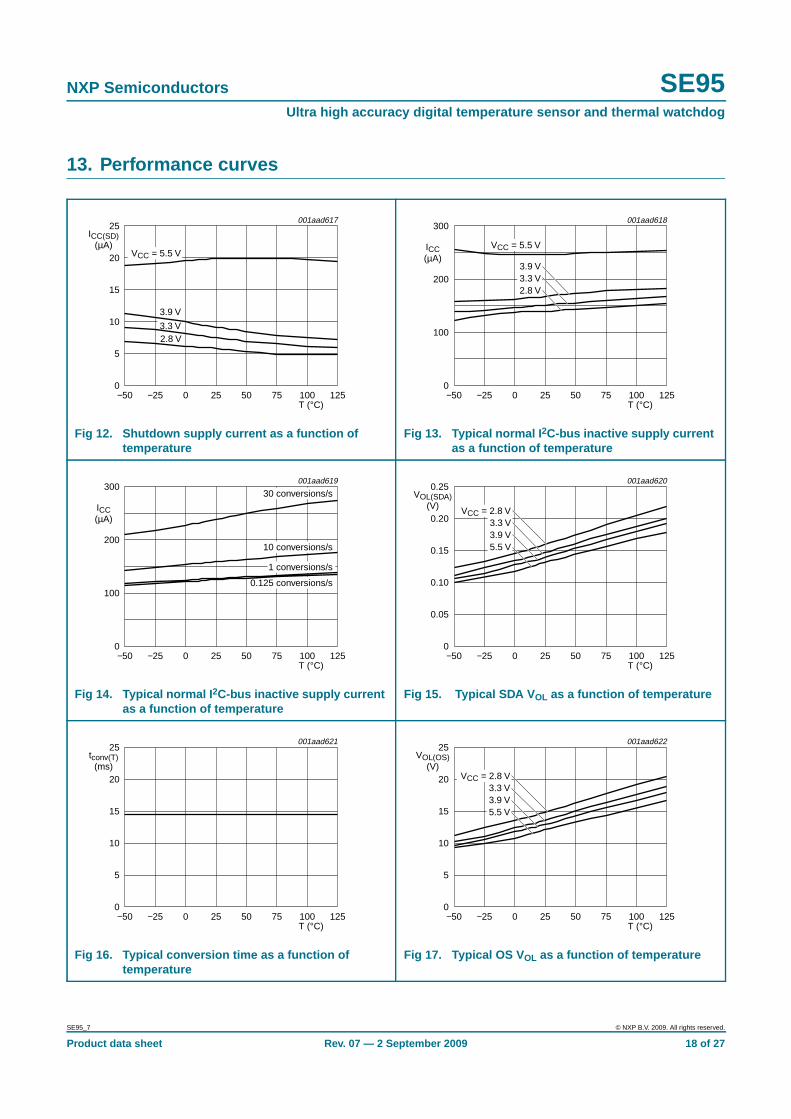
13. Performance curves
Fig 12. Shutdown supply current as a function oftemperature
Fig 13. Typical normal I 2C-bus inactive supply currentas a function of temperature
Fig 14. Typical normal I 2C-bus inactive supply currentas a function of temperature
Fig 15. Typical SDA V OL as a function of temperature
Fig 16. Typical conversion time as a function oftemperature
Fig 17. Typical OS V OL as a function of temperature
001aad617
5
15
25
20
10
ICC(SD)(µA)
0
T (°C)−50 1251000−25 25 7550
VCC = 5.5 V
3.3 V
3.9 V
2.8 V
001aad618
100
200
300
ICC(µA)
0
T (°C)−50 1251000−25 25 7550
VCC = 5.5 V
3.3 V3.9 V
2.8 V
001aad619
100
200
300
ICC(µA)
0
T (°C)−50 1251000−25 25 7550
30 conversions/s
10 conversions/s
1 conversions/s
0.125 conversions/s
001aad620
0.05
0.15
0.25
0.20
0.10
VOL(SDA)(V)
0
T (°C)−50 1251000−25 25 7550
VCC = 2.8 V3.3 V3.9 V5.5 V
001aad621
5
15
25
20
10
tconv(T)(ms)
0
T (°C)−50 1251000−25 25 7550
001aad622
5
15
25
20
10
VOL(OS)(V)
0
T (°C)−50 1251000−25 25 7550
VCC = 2.8 V3.3 V3.9 V5.5 V
SE95_7 © NXP B.V. 2009. All rights reserved.
Product data sheet Rev. 07 — 2 September 2009 18 of 27

NXP Semiconductors SE95Ultra high accuracy digital temperature sensor and thermal watchdog
14. Application information
The SE95 is sensitive to power supplies with ramp-up time ≤2 ms and could NACK orhang the I2C-bus. In most applications the SE95 will function properly since powersupplies have a >2 ms ramp-up time. If the power supply ramp-up time is ≤2 ms, use anRC network with R = 300 Ω and C = 10 µF, as shown in Figure 18, to add about 3 ms tothe ramp-up time. The 10 µF capacitor is the same as the bypass capacitor that istypically used to prevent fluctuations on the power supply. The 300 Ω resistor will reducethe supply voltage by about 45 mV since the SE95 supply current is about 150 µA. Ensurethe SE95 is the only device connected to the end of 300 Ω resistor since additionaldevices would draw more current and cause a larger voltage drop across the resistor.
Fig 18. Typical application circuit
002aae891
10 kΩ
SE95 detector or interrupt line
SCL
SDA
A2
A1
A0
OS
VCC
power supply
GND
digital logicor tie to
VCC or GND
I2C-bus
10 µF
300 Ωpower supply
SE95_7 © NXP B.V. 2009. All rights reserved.
Product data sheet Rev. 07 — 2 September 2009 19 of 27
NXP Semiconductors SE95Ultra high accuracy digital temperature sensor and thermal watchdog
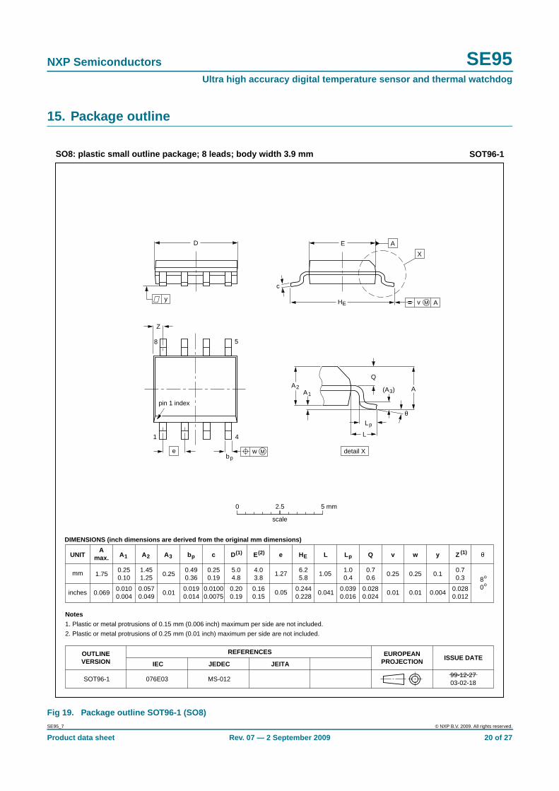
15. Package outline
Fig 19. Package outline SOT96-1 (SO8)
UNITA
max. A1 A2 A3 bp c D(1) E(2) (1)e HE L L p Q Zywv θ
REFERENCESOUTLINEVERSION
EUROPEANPROJECTION ISSUE DATE
IEC JEDEC JEITA
mm
inches
1.750.250.10
1.451.25
0.250.490.36
0.250.19
5.04.8
4.03.8
1.276.25.8
1.050.70.6
0.70.3 8
0
o
o
0.25 0.10.25
DIMENSIONS (inch dimensions are derived from the original mm dimensions)
Notes
1. Plastic or metal protrusions of 0.15 mm (0.006 inch) maximum per side are not included.
2. Plastic or metal protrusions of 0.25 mm (0.01 inch) maximum per side are not included.
1.00.4
SOT96-1
X
w M
θ
AA1
A2
bp
D
HE
Lp
Q
detail X
E
Z
e
c
L
v M A
(A )3
A
4
5
pin 1 index
1
8
y
076E03 MS-012
0.0690.0100.004
0.0570.049
0.010.0190.014
0.01000.0075
0.200.19
0.160.15
0.050.2440.228
0.0280.024
0.0280.012
0.010.010.041 0.0040.0390.016
0 2.5 5 mm
scale
SO8: plastic small outline package; 8 leads; body width 3.9 mm SOT96-1
99-12-2703-02-18
SE95_7 © NXP B.V. 2009. All rights reserved.
Product data sheet Rev. 07 — 2 September 2009 20 of 27

NXP Semiconductors SE95Ultra high accuracy digital temperature sensor and thermal watchdog
Fig 20. Package outline SOT505-1 (TSSOP8)
UNIT A1A
max.A2 A3 bp LHE Lp w yvc eD(1) E(2) Z(1) θ
REFERENCESOUTLINEVERSION
EUROPEANPROJECTION ISSUE DATE
IEC JEDEC JEITA
mm 0.150.05
0.950.80
0.450.25
0.280.15
3.12.9
3.12.9
0.655.14.7
0.700.35
6°0°
0.1 0.10.10.94
DIMENSIONS (mm are the original dimensions)
Notes
1. Plastic or metal protrusions of 0.15 mm maximum per side are not included.
2. Plastic or metal protrusions of 0.25 mm maximum per side are not included.
0.70.4
SOT505-1 99-04-0903-02-18
w Mbp
D
Z
e
0.25
1 4
8 5
θ
AA2A1
Lp
(A3)
detail X
L
HE
E
c
v M A
XA
y
2.5 5 mm0
scale
TSSOP8: plastic thin shrink small outline package; 8 leads; body width 3 mm SOT505-1
1.1
pin 1 index
SE95_7 © NXP B.V. 2009. All rights reserved.
Product data sheet Rev. 07 — 2 September 2009 21 of 27

NXP Semiconductors SE95Ultra high accuracy digital temperature sensor and thermal watchdog
16. Soldering of SMD packages
This text provides a very brief insight into a complex technology. A more in-depth accountof soldering ICs can be found in Application Note AN10365 “Surface mount reflowsoldering description”.
16.1 Introduction to solderingSoldering is one of the most common methods through which packages are attached toPrinted Circuit Boards (PCBs), to form electrical circuits. The soldered joint provides boththe mechanical and the electrical connection. There is no single soldering method that isideal for all IC packages. Wave soldering is often preferred when through-hole andSurface Mount Devices (SMDs) are mixed on one printed wiring board; however, it is notsuitable for fine pitch SMDs. Reflow soldering is ideal for the small pitches and highdensities that come with increased miniaturization.
16.2 Wave and reflow solderingWave soldering is a joining technology in which the joints are made by solder coming froma standing wave of liquid solder. The wave soldering process is suitable for the following:
• Through-hole components
• Leaded or leadless SMDs, which are glued to the surface of the printed circuit board
Not all SMDs can be wave soldered. Packages with solder balls, and some leadlesspackages which have solder lands underneath the body, cannot be wave soldered. Also,leaded SMDs with leads having a pitch smaller than ~0.6 mm cannot be wave soldered,due to an increased probability of bridging.
The reflow soldering process involves applying solder paste to a board, followed bycomponent placement and exposure to a temperature profile. Leaded packages,packages with solder balls, and leadless packages are all reflow solderable.
Key characteristics in both wave and reflow soldering are:
• Board specifications, including the board finish, solder masks and vias
• Package footprints, including solder thieves and orientation
• The moisture sensitivity level of the packages
• Package placement
• Inspection and repair
• Lead-free soldering versus SnPb soldering
16.3 Wave solderingKey characteristics in wave soldering are:
• Process issues, such as application of adhesive and flux, clinching of leads, boardtransport, the solder wave parameters, and the time during which components areexposed to the wave
• Solder bath specifications, including temperature and impurities
SE95_7 © NXP B.V. 2009. All rights reserved.
Product data sheet Rev. 07 — 2 September 2009 22 of 27

NXP Semiconductors SE95Ultra high accuracy digital temperature sensor and thermal watchdog
16.4 Reflow solderingKey characteristics in reflow soldering are:
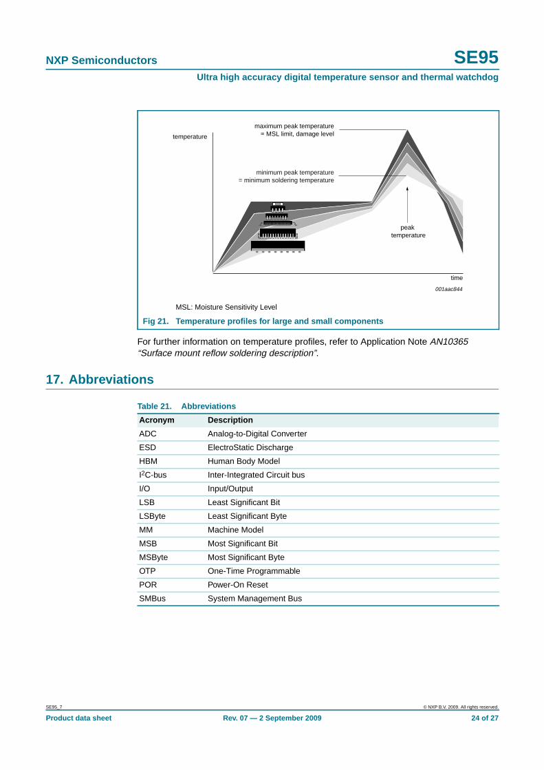
• Lead-free versus SnPb soldering; note that a lead-free reflow process usually leads tohigher minimum peak temperatures (see Figure 21) than a SnPb process, thusreducing the process window
• Solder paste printing issues including smearing, release, and adjusting the processwindow for a mix of large and small components on one board
• Reflow temperature profile; this profile includes preheat, reflow (in which the board isheated to the peak temperature) and cooling down. It is imperative that the peaktemperature is high enough for the solder to make reliable solder joints (a solder pastecharacteristic). In addition, the peak temperature must be low enough that thepackages and/or boards are not damaged. The peak temperature of the packagedepends on package thickness and volume and is classified in accordance withTable 19 and 20
Moisture sensitivity precautions, as indicated on the packing, must be respected at alltimes.
Studies have shown that small packages reach higher temperatures during reflowsoldering, see Figure 21.
Table 19. SnPb eutectic process (from J-STD-020C)
Package thickness (mm) Package reflow temperature ( °C)
Volume (mm 3)
< 350 ≥ 350
< 2.5 235 220
≥ 2.5 220 220
Table 20. Lead-free process (from J-STD-020C)
Package thickness (mm) Package reflow temperature ( °C)
Volume (mm 3)
< 350 350 to 2000 > 2000
< 1.6 260 260 260
1.6 to 2.5 260 250 245
> 2.5 250 245 245
SE95_7 © NXP B.V. 2009. All rights reserved.
Product data sheet Rev. 07 — 2 September 2009 23 of 27
NXP Semiconductors SE95Ultra high accuracy digital temperature sensor and thermal watchdog
For further information on temperature profiles, refer to Application Note AN10365“Surface mount reflow soldering description”.
17. Abbreviations
MSL: Moisture Sensitivity Level
Fig 21. Temperature profiles for large and small components
001aac844
temperature
time
minimum peak temperature= minimum soldering temperature
maximum peak temperature= MSL limit, damage level
peak temperature
Table 21. Abbreviations
Acronym Description
ADC Analog-to-Digital Converter
ESD ElectroStatic Discharge
HBM Human Body Model
I2C-bus Inter-Integrated Circuit bus
I/O Input/Output
LSB Least Significant Bit
LSByte Least Significant Byte
MM Machine Model
MSB Most Significant Bit
MSByte Most Significant Byte
OTP One-Time Programmable
POR Power-On Reset
SMBus System Management Bus
SE95_7 © NXP B.V. 2009. All rights reserved.
Product data sheet Rev. 07 — 2 September 2009 24 of 27

NXP Semiconductors SE95Ultra high accuracy digital temperature sensor and thermal watchdog
18. Revision history
Table 22. Revision history
Document ID Release date Data sheet status Change notice Supersedes
SE95_7 20090902 Product data sheet - SE95_6
Modifications: • Figure 1 “Block diagram of SE95”: changed from “AVD CONTOL” to “ADC CONTROL”
• Section 14 “Application information”:
– Added first paragraph
– Figure 18 “Typical application circuit” modified
• Added soldering information
• Added Section 17 “Abbreviations”
SE95_6 20090604 Product data sheet - SE95_5
SE95_5 20071213 Product data sheet - SE95_4
SE95_4 20070212 Product data sheet - SE95_3
SE95_3(9397 750 14388)
20051212 Product data sheet - SE95_2
SE95_2(9397 750 14163)
20041005 Objective specification - SE95_1
SE95_1(9397 750 10265)
20031003 Objective specification - -
SE95_7 © NXP B.V. 2009. All rights reserved.
Product data sheet Rev. 07 — 2 September 2009 25 of 27

NXP Semiconductors SE95Ultra high accuracy digital temperature sensor and thermal watchdog
19. Legal information
19.1 Data sheet status
[1] Please consult the most recently issued document before initiating or completing a design.
[2] The term ‘short data sheet’ is explained in section “Definitions”.
[3] The product status of device(s) described in this document may have changed since this document was published and may differ in case of multiple devices. The latest product statusinformation is available on the Internet at URL http://www.nxp.com.
19.2 Definitions
Draft — The document is a draft version only. The content is still underinternal review and subject to formal approval, which may result inmodifications or additions. NXP Semiconductors does not give anyrepresentations or warranties as to the accuracy or completeness ofinformation included herein and shall have no liability for the consequences ofuse of such information.
Short data sheet — A short data sheet is an extract from a full data sheetwith the same product type number(s) and title. A short data sheet is intendedfor quick reference only and should not be relied upon to contain detailed andfull information. For detailed and full information see the relevant full datasheet, which is available on request via the local NXP Semiconductors salesoffice. In case of any inconsistency or conflict with the short data sheet, thefull data sheet shall prevail.
19.3 Disclaimers
General — Information in this document is believed to be accurate andreliable. However, NXP Semiconductors does not give any representations orwarranties, expressed or implied, as to the accuracy or completeness of suchinformation and shall have no liability for the consequences of use of suchinformation.
Right to make changes — NXP Semiconductors reserves the right to makechanges to information published in this document, including withoutlimitation specifications and product descriptions, at any time and withoutnotice. This document supersedes and replaces all information supplied priorto the publication hereof.
Suitability for use — NXP Semiconductors products are not designed,authorized or warranted to be suitable for use in medical, military, aircraft,space or life support equipment, nor in applications where failure ormalfunction of an NXP Semiconductors product can reasonably be expectedto result in personal injury, death or severe property or environmental
damage. NXP Semiconductors accepts no liability for inclusion and/or use ofNXP Semiconductors products in such equipment or applications andtherefore such inclusion and/or use is at the customer’s own risk.
Applications — Applications that are described herein for any of theseproducts are for illustrative purposes only. NXP Semiconductors makes norepresentation or warranty that such applications will be suitable for thespecified use without further testing or modification.
Limiting values — Stress above one or more limiting values (as defined inthe Absolute Maximum Ratings System of IEC 60134) may cause permanentdamage to the device. Limiting values are stress ratings only and operation ofthe device at these or any other conditions above those given in theCharacteristics sections of this document is not implied. Exposure to limitingvalues for extended periods may affect device reliability.
Terms and conditions of sale — NXP Semiconductors products are soldsubject to the general terms and conditions of commercial sale, as publishedat http://www.nxp.com/profile/terms, including those pertaining to warranty,intellectual property rights infringement and limitation of liability, unlessexplicitly otherwise agreed to in writing by NXP Semiconductors. In case ofany inconsistency or conflict between information in this document and suchterms and conditions, the latter will prevail.
No offer to sell or license — Nothing in this document may be interpretedor construed as an offer to sell products that is open for acceptance or thegrant, conveyance or implication of any license under any copyrights, patentsor other industrial or intellectual property rights.
Export control — This document as well as the item(s) described hereinmay be subject to export control regulations. Export might require a priorauthorization from national authorities.
19.4 TrademarksNotice: All referenced brands, product names, service names and trademarksare the property of their respective owners.
I2C-bus — logo is a trademark of NXP B.V.
20. Contact information
For more information, please visit: http://www .nxp.com
For sales office addresses, please send an email to: salesad [email protected]
Document status [1] [2] Product status [3] Definition
Objective [short] data sheet Development This document contains data from the objective specification for product development.
Preliminary [short] data sheet Qualification This document contains data from the preliminary specification.
Product [short] data sheet Production This document contains the product specification.
SE95_7 © NXP B.V. 2009. All rights reserved.
Product data sheet Rev. 07 — 2 September 2009 26 of 27

NXP Semiconductors SE95Ultra high accuracy digital temperature sensor and thermal watchdog
21. Contents
1 General description . . . . . . . . . . . . . . . . . . . . . . 12 Features . . . . . . . . . . . . . . . . . . . . . . . . . . . . . . . 23 Applications . . . . . . . . . . . . . . . . . . . . . . . . . . . . 24 Ordering information . . . . . . . . . . . . . . . . . . . . . 25 Block diagram . . . . . . . . . . . . . . . . . . . . . . . . . . 36 Pinning information . . . . . . . . . . . . . . . . . . . . . . 36.1 Pinning . . . . . . . . . . . . . . . . . . . . . . . . . . . . . . . 36.2 Pin description . . . . . . . . . . . . . . . . . . . . . . . . . 37 Functional description . . . . . . . . . . . . . . . . . . . 47.1 General operation . . . . . . . . . . . . . . . . . . . . . . . 47.2 OS output and polarity . . . . . . . . . . . . . . . . . . . 67.3 OS comparator and interrupt modes . . . . . . . . 67.4 OS fault queue . . . . . . . . . . . . . . . . . . . . . . . . . 67.5 Shutdown mode . . . . . . . . . . . . . . . . . . . . . . . . 77.6 Power-up default and power-on reset . . . . . . . . 78 I2C-bus serial interface . . . . . . . . . . . . . . . . . . . 78.1 Slave address . . . . . . . . . . . . . . . . . . . . . . . . . . 78.2 Register list . . . . . . . . . . . . . . . . . . . . . . . . . . . . 88.3 Register pointer . . . . . . . . . . . . . . . . . . . . . . . . 88.4 Configuration register . . . . . . . . . . . . . . . . . . . . 98.5 Temperature register. . . . . . . . . . . . . . . . . . . . . 98.6 Overtemperature shutdown threshold
and hysteresis registers . . . . . . . . . . . . . . . . . 118.7 Protocols for writing and reading
the registers . . . . . . . . . . . . . . . . . . . . . . . . . . 129 Limiting values. . . . . . . . . . . . . . . . . . . . . . . . . 1510 Recommended operating conditions. . . . . . . 1511 Static characteristics. . . . . . . . . . . . . . . . . . . . 1612 Dynamic characteristics . . . . . . . . . . . . . . . . . 1713 Performance curves . . . . . . . . . . . . . . . . . . . . 1814 Application information. . . . . . . . . . . . . . . . . . 1915 Package outline . . . . . . . . . . . . . . . . . . . . . . . . 2016 Soldering of SMD packages . . . . . . . . . . . . . . 2216.1 Introduction to soldering . . . . . . . . . . . . . . . . . 2216.2 Wave and reflow soldering . . . . . . . . . . . . . . . 2216.3 Wave soldering . . . . . . . . . . . . . . . . . . . . . . . . 2216.4 Reflow soldering . . . . . . . . . . . . . . . . . . . . . . . 2317 Abbreviations . . . . . . . . . . . . . . . . . . . . . . . . . . 2418 Revision history . . . . . . . . . . . . . . . . . . . . . . . . 2519 Legal information. . . . . . . . . . . . . . . . . . . . . . . 2619.1 Data sheet status . . . . . . . . . . . . . . . . . . . . . . 2619.2 Definitions . . . . . . . . . . . . . . . . . . . . . . . . . . . . 2619.3 Disclaimers . . . . . . . . . . . . . . . . . . . . . . . . . . . 2619.4 Trademarks . . . . . . . . . . . . . . . . . . . . . . . . . . . 26
20 Contact information . . . . . . . . . . . . . . . . . . . . 2621 Contents. . . . . . . . . . . . . . . . . . . . . . . . . . . . . . 27
© NXP B.V. 2009. All rights reserved.For more information, please visit: http://www.nxp.comFor sales office addresses, please send an email to: [email protected]
Date of release: 2 September 2009
Document identifier: SE95_7
Please be aware that important notices concerning this document and the product(s)described herein, have been included in section ‘Legal information’.