Embed Size (px)
Citation preview
SE 1: Software RequirementsSpecification and AnalysisLecture 9: UML Class (Concept), Object,
Communication Diagrams
Nancy Day, Davor Svetinovic
http://www.student.cs.uwaterloo.ca/˜cs445/Winter2006
uw.cs.cs445
U Waterloo SE1 (Winter 2006) – p.1/54
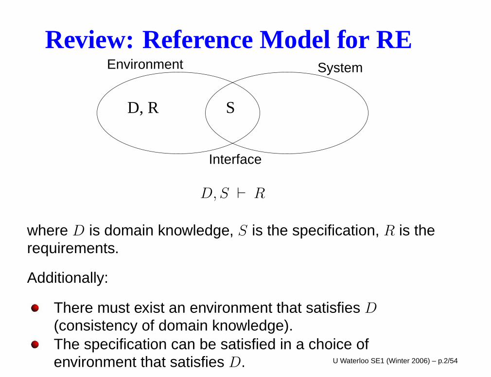
Review: Reference Model for REEnvironment
Interface
System
D, R S
D, S ` R
where D is domain knowledge, S is the specification, R is therequirements.
Additionally:
There must exist an environment that satisfies D
(consistency of domain knowledge).The specification can be satisfied in a choice ofenvironment that satisfies D. U Waterloo SE1 (Winter 2006) – p.2/54
Today’s AgendaClass (concept) diagrams (domain models)
ClassesAssociationsAttributesOperationsGeneralization, aggregation, compositionNavigabilityMultiplicityObject diagrams
Communication DiagramsPackage Diagrams
Example: Library System (next class we will continue with thestopwatch)
Readings: Arlow and Neustadt Ch. 6,7,8,9 (skip 9.5), 10,11,18.1-18.5
U Waterloo SE1 (Winter 2006) – p.3/54
SE1 ProcessUse case descriptionsUse case diagramSystem sequence diagram (one per use case)System state diagramNext: object-oriented decomposition
Divide the system into objects that are created,deleted, and can run concurrently.Classes are sets of objects with common behaviourA set of objects running concurrently accomplishes thebehaviour of the system as described in the systemstate diagram (and therefore use cases and systemsequence diagrams).Concept-level sequence (or communication diagrams)illustrate how a set of collaborating objects accomplisheach system sequence diagram.
U Waterloo SE1 (Winter 2006) – p.4/54
Objects
An object is “A discrete entity with a well-defined boundarythat encapsulates state and behavior.” [Rumbaugh]
Every object has:
an identity
state (attribute values and relationships with other objectsat a particular point in time)
behaviour (services offered) – invoking an operation maycause a change in state
An operation is the specification of a behaviour.
A method is the implementation of the behaviour.
U Waterloo SE1 (Winter 2006) – p.5/54
Objects
“Objects collaborate to perform the functions of the system.What this means is that objects form links to other objectsand send messages back and forth along those links.” [Arlowand Neustadt]
The messages are invocations of operations offered by theobject.
U Waterloo SE1 (Winter 2006) – p.6/54
ClassesA class is a collection of objects with a common set offeatures (attributes, operations, relationships). (think “type”)
Every object belongs to one class.
A class diagram depicts the kind of objects involved in theproblem and their static relationships. It is a form of ERD.
Elements of a class diagram:
Classes
NameAttributesOperations
Relationships:
AssociationsGeneralizations (is-a)Aggregations, Compositions (has-a/whole-part)
U Waterloo SE1 (Winter 2006) – p.7/54
Example
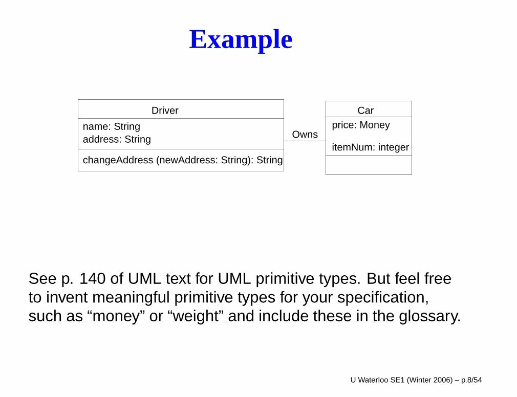
name: Stringaddress: String
changeAddress (newAddress: String): String
Driverprice: Money
itemNum: integer
Car
Owns
See p. 140 of UML text for UML primitive types. But feel freeto invent meaningful primitive types for your specification,such as “money” or “weight” and include these in the glossary.
U Waterloo SE1 (Winter 2006) – p.8/54
Class Diagrams: Perspectives
UML class diagrams can be used in three distinct waysdepending on the phase of system development:
According to Fowler and Cook&Daniels:
1. Conceptual (Domain Models)
requirements phase (elaboration phase)
the diagram represents the entities in theproblem/business domain
not necessarily a direct mapping to how these will beimplemented (although they may end up being classesin the software)
also called analysis classes
U Waterloo SE1 (Winter 2006) – p.9/54
Class Diagrams: Perspectives
2. Design
the diagram depicts only the interfaces of softwareclasses, but still avoids implementation details
information hiding
3. Implementation
the diagram depicts interfaces and implementations ofclasses
U Waterloo SE1 (Winter 2006) – p.10/54
Conceptual Diagrams
This course is about writing conceptual diagrams (domainmodels):
Diagrams that describe the system’s behaviour in termsof how it affects its environment
Describe real-world entities – the information the systemwill monitor, store, transform, analyze, display, etc;physical and conceptual
Larman refers to the concept (class) diagram for RE as a“visual dictionary”
U Waterloo SE1 (Winter 2006) – p.11/54
What is a class?
Classes are entities from the problem domain:
“crisp abstraction of the problem domain” [Arlow andNeustadt]
map to real-world concepts
any information that the system stores, analyzes,transforms, displays, etc.
transient objects (e.g., business transactions, phoneconversations)
actors that interact with system. (If so, show the boundaryof the system on your class diagram.)
Classes are named, usually, by short singular nouns.
Speak the customer’s language! U Waterloo SE1 (Winter 2006) – p.12/54
Attributes
An attribute is simple data associated with a class.
The data that is too simple to have a class of its own (e.g.,numbers, text).
Attributes can also be viewed as properties of a class,information that distinguishes one instance of the class fromanother instance. They are distinguishing characteristics ofthe objects.
Syntax: name : type = default value(default value is optional)
Again, these are just the attributes relevant at the RE level ofdescription.
U Waterloo SE1 (Winter 2006) – p.13/54
Operations
Operations are the responsibilities/services of an object in theclass.
query value of an object’s attributes
transform values of object’s attributes
may result in state changes
Syntax: name (parameters) : return-type {properties}
Together, a class’s attributes and operations document thepurpose of the class — what information it maintains, andhow can that information be manipulated.
U Waterloo SE1 (Winter 2006) – p.14/54
Operations
Properties can be used to specify an operation’s pre- andpost-conditions. They might not appear on the class diagram,but instead be defined in a section following the class diagram(as in your SRS).
You don’t need to show operations that query attributes onthe class diagram.
You do not need to show create and delete operations on theclass diagram.
U Waterloo SE1 (Winter 2006) – p.15/54
Associations
An association is a relationship between classes.
Relationships between objects, i.e., instances of associationsare called links.
A link allows messages to be sent from one object to another.These are operation invocations.
Associations are names, usually short verbs. Some peoplename every association. Others name associations onlywhen such names will improve understanding. e.g., avoidnames like “is related to”, and “has”.
It is possible to have two associations between the same twoclasses.
U Waterloo SE1 (Winter 2006) – p.16/54
Associations
We want to avoid having too many associations, whichcreates “visual noise”.
Larman distinguishes two types of associations:
needs-to-know – a relation between classes that needs tobe remembered
comprehension-only – information that helps us tounderstand the domain
Mostly we want to have “needs-to-know” associations.
U Waterloo SE1 (Winter 2006) – p.17/54
Common Associations List
Examples of common associations (Larman, p. 156):
A is owned by BA is a description for BA is a physical part of B (special type of association)A is a logical part of B (special type of association)etc.
Avoid making derivable information an association.
U Waterloo SE1 (Winter 2006) – p.18/54
Method
To build a conceptual model:
1. Identify candidate list of classes
2. Draw class diagram
3. Add associations
4. Add attributes
5. Add operations
U Waterloo SE1 (Winter 2006) – p.19/54
Finding Classes
There are a variety of methods:
Noun/Verb Analysis
Extract from System Sequence and State Diagrams (nextclass)
CRC (Class Responsibilities Collaborators) Analysis
brainstorm about all the entities that are relevant to thesystem and their relationships
use sticky notes and a whiteboard
You can use multiple approaches and then consolidate.
Expect this process to be iterative!
U Waterloo SE1 (Winter 2006) – p.20/54
Noun/Verb Analysis
Go through the use cases:
nouns or noun phrases –> classes or attributes orassociations
verbs or verb phrases –> operations
Watch out for ambiguities and redundant concepts(synonyms and homonyms)
Watch for hidden classes (useful abstractions that makethe diagram simpler)
Attributes are things that seem to be part of another thing.
U Waterloo SE1 (Winter 2006) – p.21/54
Common Types of Classesinterface/boundary classes – those that communicatewith external actors (user interfaces, system/deviceinterfaces)
controller/manager classes – coordinate systembehaviour; cut across multiple use cases
“entity” classes – simple behaviour – get and set values
“specification or description class”
If a description of an item is needed independent ofthe existence of the item
Often found for items that can be deleted
Example: may require a description of a serviceseparate from the actual sold services.
These common types of classes can be designated usingstereotypes. U Waterloo SE1 (Winter 2006) – p.22/54
Library Example
A library system has patrons who borrow publications using aloan.
The publications can be books or periodicals.
There are due dates and fines associated with loans.
The library tracks the accumulated fines of all patrons.
U Waterloo SE1 (Winter 2006) – p.23/54
Association Class
An association class allows you to add attributes, operations,and other features to an association.
Sometimes there is information that cannot be attributed tosolely one class or another, but is really information about theassociation.
Syntax: Class connected to association by dashed line.
There must be only 1 instance of association class betweenany two associated objects – i.e., the instance must beuniquely determined.
U Waterloo SE1 (Winter 2006) – p.24/54
Generalization
Generalization indicates a sub-class relation.
All instances of the subclass are instances of the superclass.
A subclass inherits all attributes, operations and associationsof the parent.
The common attributes and operations are placed in thesuperclass; subclasses extend the attributes, operations, andassociations as they need them.
Syntax: open triangle at the superclass end of the association
U Waterloo SE1 (Winter 2006) – p.25/54
Generalization
Each level in the generalization hierarchy should be at thesame level of abstraction.
In RE, generalization is not for the sake of code reuse!Explore inheritance if these abstractions help make the modelsimpler. Sometimes looking a the general case can result insimpler models.
U Waterloo SE1 (Winter 2006) – p.26/54
Generalization
Is property permanent for object or does it change at runtime?
If property is permanent for an object, then the property is thebasis for a subclass. Objects of differing subclasses can havedifferent components.
If property changes at run time for an object, then theproperty is an attribute to be set at run time.
The components of an object do not change at run time.
U Waterloo SE1 (Winter 2006) – p.27/54
Generalization
Generalization is often called the “is-a” relationship.
Often, we can use the “is-a” test to see if you have ageneralization relation between two classes:
Can you say that an instance of one class “is-a” an instanceof the other class?
Example: A student in this class is a student at the Universityof Waterloo.
U Waterloo SE1 (Winter 2006) – p.28/54
Warning!
The “is-a” test doesn’t always work!
From Fowler:
1. Shep is a Border Collie.
2. A Border Collie is a Dog.
3. Dogs are Animals
4. A Border Collie is a Breed.
5. Dog is a Species
U Waterloo SE1 (Winter 2006) – p.29/54
Whole-part Associations
aggregation
composition
Also called “has-a” relationships.
These associations can have multiplicities.
These whole-part associations cannot contain cycles (i.e., anobject can never directly or indirectly be part of itself).
They are transitive.
U Waterloo SE1 (Winter 2006) – p.30/54
Aggregation
Aggregation is the “part of” relation, in which one objectconsists of the associated objects.
If a complex entity is decomposed to reveal its pieces, e.g., aproject team is made up of its members, we want to depictthis type of relationship between compound class andcomponent classes.
Examples of aggregation:
computer and its peripherals
U Waterloo SE1 (Winter 2006) – p.31/54
Composition
Composition is a particular kind of aggregation in which onecomponent is physically part of another (single) component.The subcomponent dies if the whole component dies. Thesubcomponent can only be part of one aggregate at a time.
We would not want to use this notation for a team beingcomposed of its team members, because it would imply thatthe members die when the team dies.
Examples of composition:
a car is composed of an engine, wheels, a gear box, etc.
a periodical is composed of articles; the articles don’thave a life outside of the periodical.
a tree and its leaves U Waterloo SE1 (Winter 2006) – p.32/54
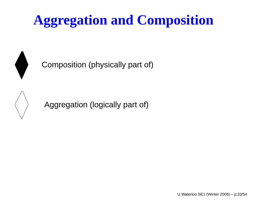
Aggregation and Composition
Composition (physically part of)
Aggregation (logically part of)
U Waterloo SE1 (Winter 2006) – p.33/54
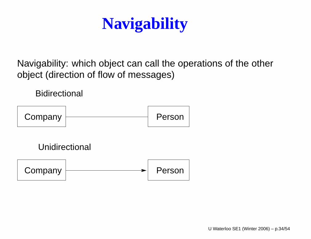
Navigability
Navigability: which object can call the operations of the otherobject (direction of flow of messages)
PersonCompany
PersonCompany
Bidirectional
Unidirectional
U Waterloo SE1 (Winter 2006) – p.34/54
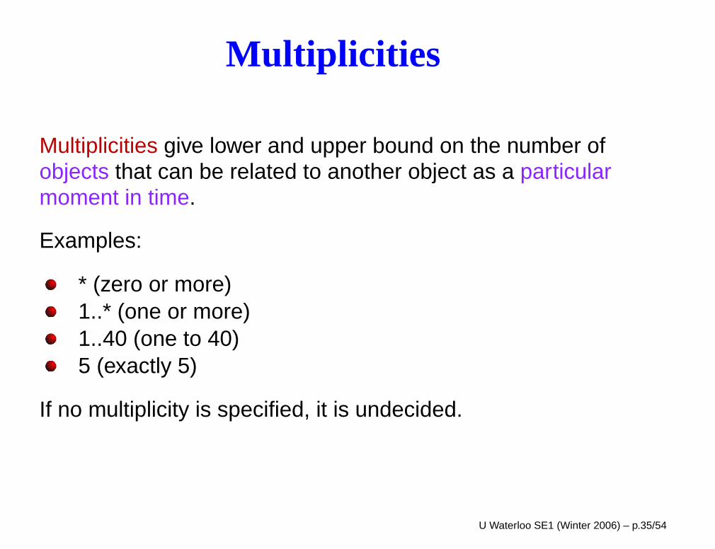
Multiplicities
Multiplicities give lower and upper bound on the number ofobjects that can be related to another object as a particularmoment in time.
Examples:
* (zero or more)1..* (one or more)1..40 (one to 40)5 (exactly 5)
If no multiplicity is specified, it is undecided.
U Waterloo SE1 (Winter 2006) – p.35/54
Object Diagrams
“An object diagram is snapshot of the of the objects of thesystem at a point in time.” (Fowler)
It shows objects (instances of classes) and links (instances ofassociation).
Object diagrams use the same syntax as UML classdiagrams, except that object names are underlined(instance_name: class).
Values for attributes can also be shown.
If there are multiple objects of the same class, use objectnames to distinguish them.
U Waterloo SE1 (Winter 2006) – p.36/54
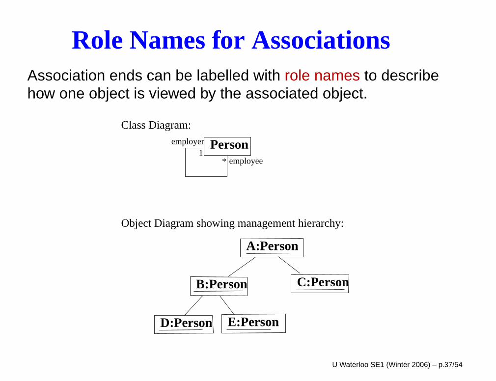
Role Names for AssociationsAssociation ends can be labelled with role names to describehow one object is viewed by the associated object.
Personemployee
employer1
*
B:Person C:Person
D:Person E:Person
A:Person
Class Diagram:
Object Diagram showing management hierarchy:
U Waterloo SE1 (Winter 2006) – p.37/54
Abstract Classes
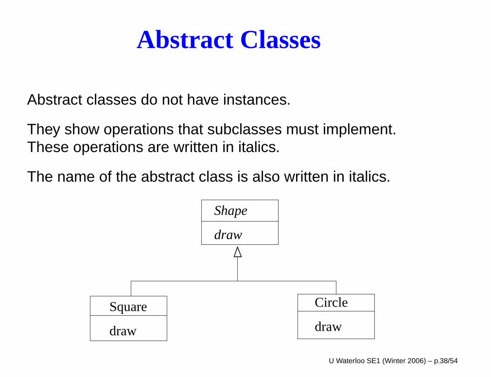
Abstract classes do not have instances.
They show operations that subclasses must implement.These operations are written in italics.
The name of the abstract class is also written in italics.
Shape
Circle
draw
Square
draw
draw
U Waterloo SE1 (Winter 2006) – p.38/54
Class Scope Attributes and Operations
Class scope attributes and operations are attributes andoperations that are applied to a class of objects, rather than toindividual objects.
Class scope attributes are used to model data values sharedby all objects of the class, as opposed to the usual situation ofeach object of the class having its own value for that attribute.
Class scope operations are class-related operations notoffered by instances of the class, e.g., create() and search()operations. (create is not usually shown on a conceptualmodel.)
Syntax: underlined attribute or operation
U Waterloo SE1 (Winter 2006) – p.39/54
Class Scope Attributes and OperationsHowever, class-scope attributes and operations are rarelyneeded at the RE level of description.
Many such operations are implicit at the RE level (e.g.,create/delete/find/count), so we don’t need to show them.They are given via associations.
An operation that is more involved than these simpleoperations, such as a “deleteUser” operation that has tocheck whether the user is involved in a call prior to deletionshould not be a class-scope operation. Rather these shouldbe operations of a “collection” (or controller) class that is in a1..* relationship with the user class.
The behaviour this method would then be specified in thestate diagram of this collection class, and during its behaviourit would call the "delete" method of the user account class.
U Waterloo SE1 (Winter 2006) – p.40/54
Qualified Association
A qualified association is an association key that identifies theobject at the other end of the association
A qualifier is a key or index used to identify one or fewerobjects from set of many objects.
Syntax: name in box at an end of an association
Often the qualifier is an attribute of the class at the other endof the association, an attribute that is recognized as uniquelyidentifying one or fewer objects of the class.
U Waterloo SE1 (Winter 2006) – p.41/54
Summary: Concept Diagrams
Classes
Associations
Attributes
Operations
Association classes
Generalization, aggregation, composition
Navigability
Multiplicity
U Waterloo SE1 (Winter 2006) – p.42/54
Good Analysis Classes
From Arlow and Neustadt:
Name reflects intentModels problem domain (in vocabulary of problemdomain)Small set of responsibilitiesHigh cohesion (responsibilities work towards same goal)Low coupling (few associations between classes)Keep it simple
U Waterloo SE1 (Winter 2006) – p.43/54
Rules of Thumb
From Arlow and Neustadt:
3-5 responsibilities per class
Every class has an association with at least one otherclass
Beware of too many or too few classes
Every class must have state! (Beware of “functoids”)
Avoid deep inheritance.
Avoid representing information that can be derived fromother classes as a class
U Waterloo SE1 (Winter 2006) – p.44/54
Project Concept Diagrams
The concept diagrams for your SRS should include:
attributes and their types
non-trivial operations and their types (set/get methods donot have to be listed)
multiplicities on all associations (note: there are NOdefault multiplicities in UML 2 – a multiplicity of 1 must beexplicitly stated)
navigability on all associations – use the convention givenin class or state otherwise
names for all non-trivial associations
U Waterloo SE1 (Winter 2006) – p.45/54
Project Concept Diagrams
In a section following the concept diagram, list anypreconditions and postconditions for the operations.
If the type information makes the diagram too large, this canbe shown only in the section following the concept diagramsor in the glossary.
You should not show whether methods are public/private – allmethods shown on a concept diagram should be public
We recommend that you show actors on your conceptdiagrams. Actors can be shown as stick figures or as classeswith the stereotype «actor» listed.
The value in showing actors is that it requires you to showmultiplicities between actors and classes, which can be avaluable requirements detail. U Waterloo SE1 (Winter 2006) – p.46/54
Validation
Follow the rules of thumb
Evaluate cohesion and coupling of classes
Include all responsibilities needed to implement systemstate diagram (more next class)
U Waterloo SE1 (Winter 2006) – p.47/54
Communication DiagramsForm of event traces over an object diagramDepicts a scenario involving multiple objectsOrder of messages can be seen by explicit sequencenumbers
A communication diagram is laid out on an object diagramand depicts specific objects and links between objects.
A communication is an annotation showing messages sentbetween objects, direction of messages, and sequencenumbers of messages.
Messages are annotated with sequence numbers to show theorder of events. The numbering can be simply 1, 2, 3, 4, ....However, to show decomposition of requests intosubrequests and subresponses, messages can be annotatedwith Dewey-Decimal like sequence numbers.
U Waterloo SE1 (Winter 2006) – p.48/54
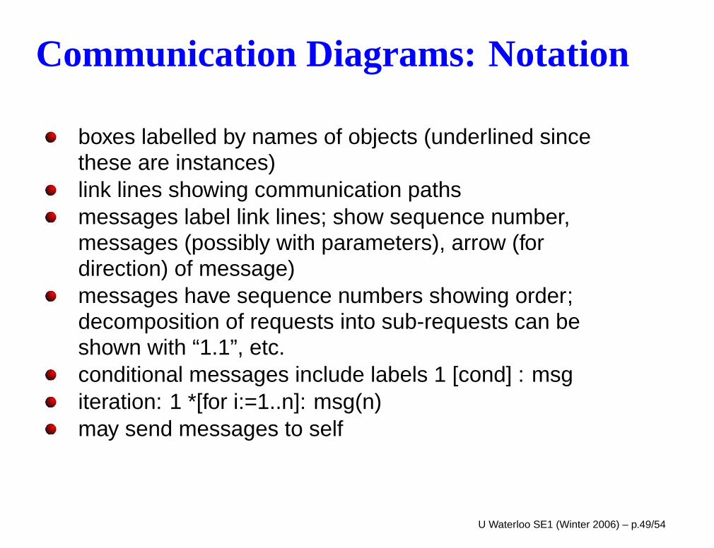
Communication Diagrams: Notation
boxes labelled by names of objects (underlined sincethese are instances)link lines showing communication pathsmessages label link lines; show sequence number,messages (possibly with parameters), arrow (fordirection) of message)messages have sequence numbers showing order;decomposition of requests into sub-requests can beshown with “1.1”, etc.conditional messages include labels 1 [cond] : msgiteration: 1 *[for i:=1..n]: msg(n)may send messages to self
U Waterloo SE1 (Winter 2006) – p.49/54
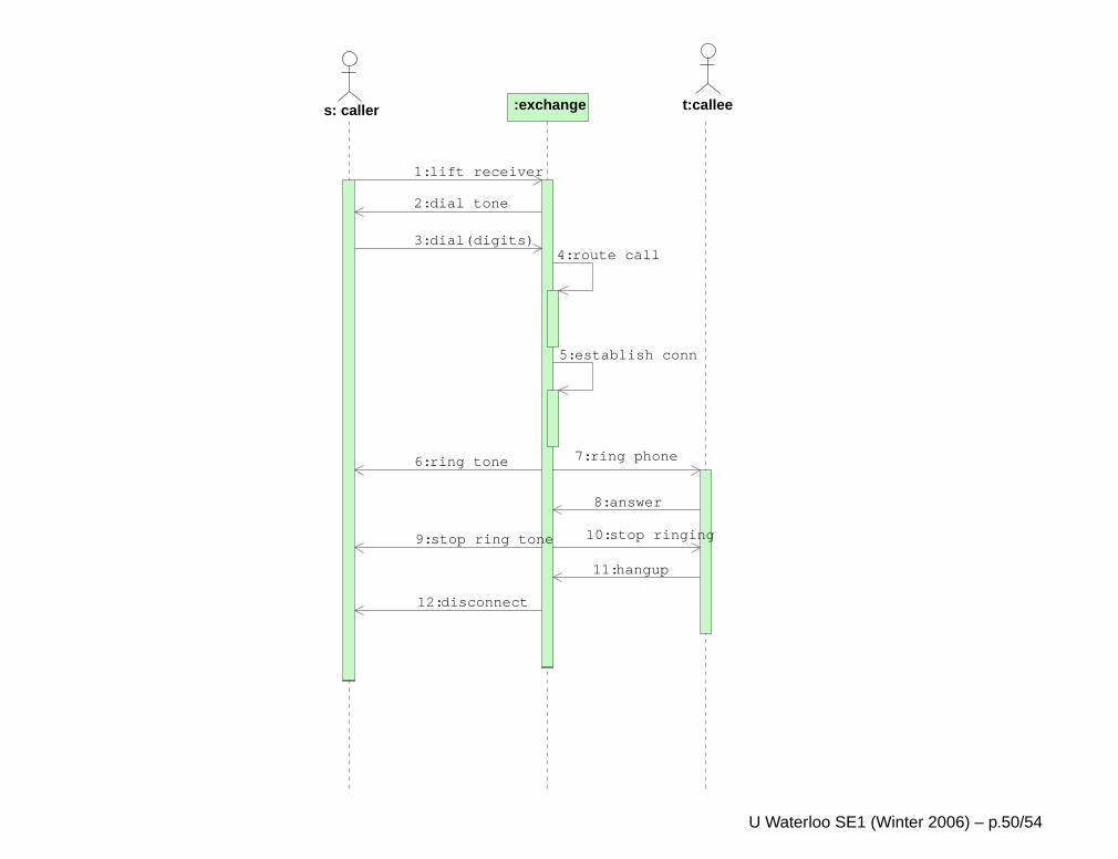
:exchanges: caller t:callee
dial(digits)3: route call4:
establish conn5:
ring phone7:
answer8:
hangup11:
lift receiver1:
dial tone2:
ring tone6:
stop ring tone9:
disconnect12:
stop ringing10:
U Waterloo SE1 (Winter 2006) – p.50/54
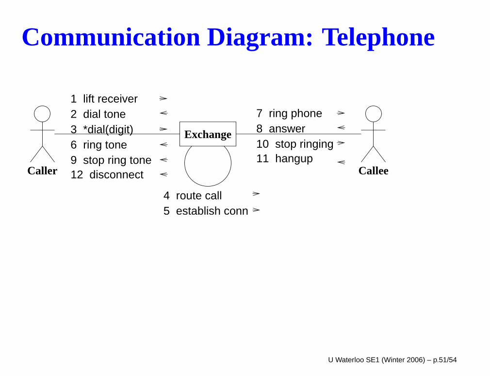
Communication Diagram: Telephone
Exchange
Caller Callee
1 lift receiver2 dial tone3 *dial(digit)6 ring tone9 stop ring tone
4 route call5 establish conn
7 ring phone8 answer10 stop ringing11 hangup
12 disconnect
U Waterloo SE1 (Winter 2006) – p.51/54
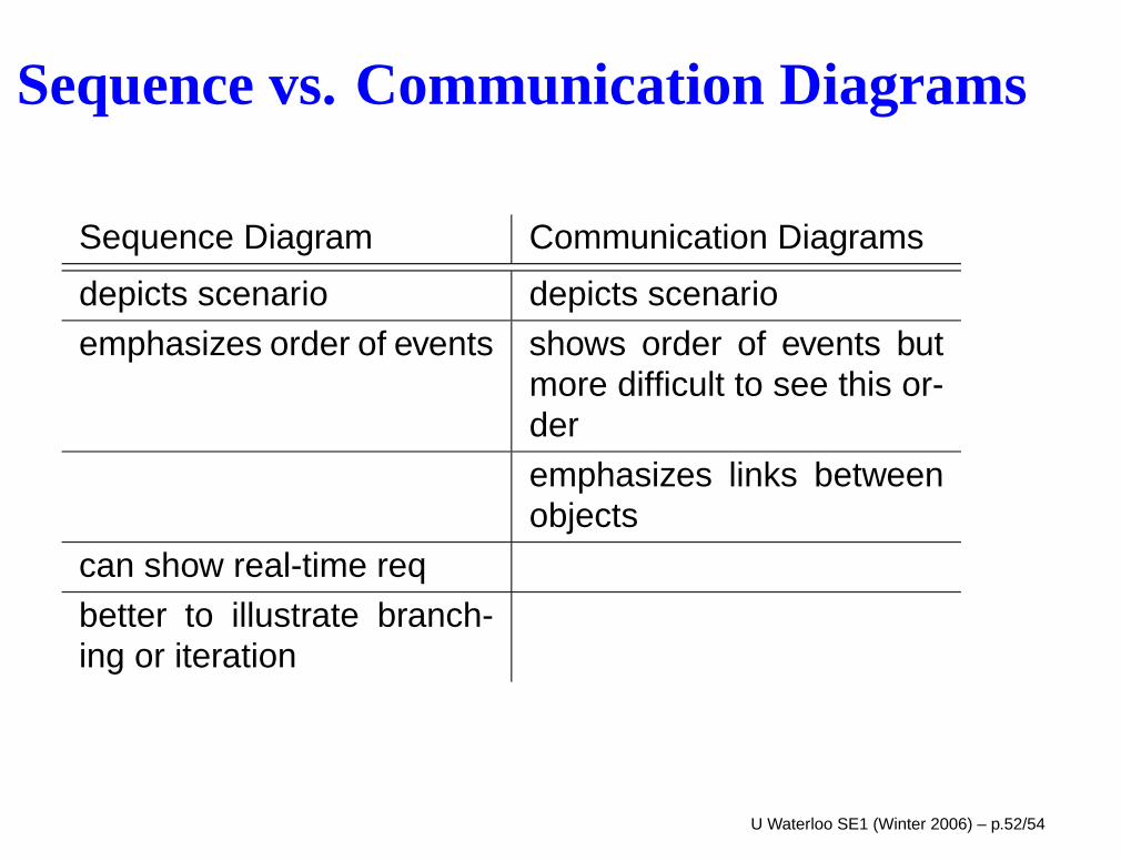
Sequence vs. Communication Diagrams
Sequence Diagram Communication Diagrams
depicts scenario depicts scenario
emphasizes order of events shows order of events butmore difficult to see this or-der
emphasizes links betweenobjects
can show real-time req
better to illustrate branch-ing or iteration
U Waterloo SE1 (Winter 2006) – p.52/54
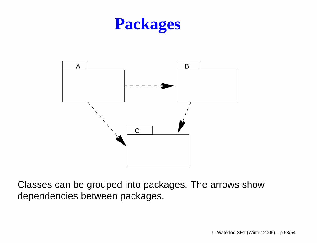
Packages
A
C
B
Classes can be grouped into packages. The arrows showdependencies between packages.
U Waterloo SE1 (Winter 2006) – p.53/54
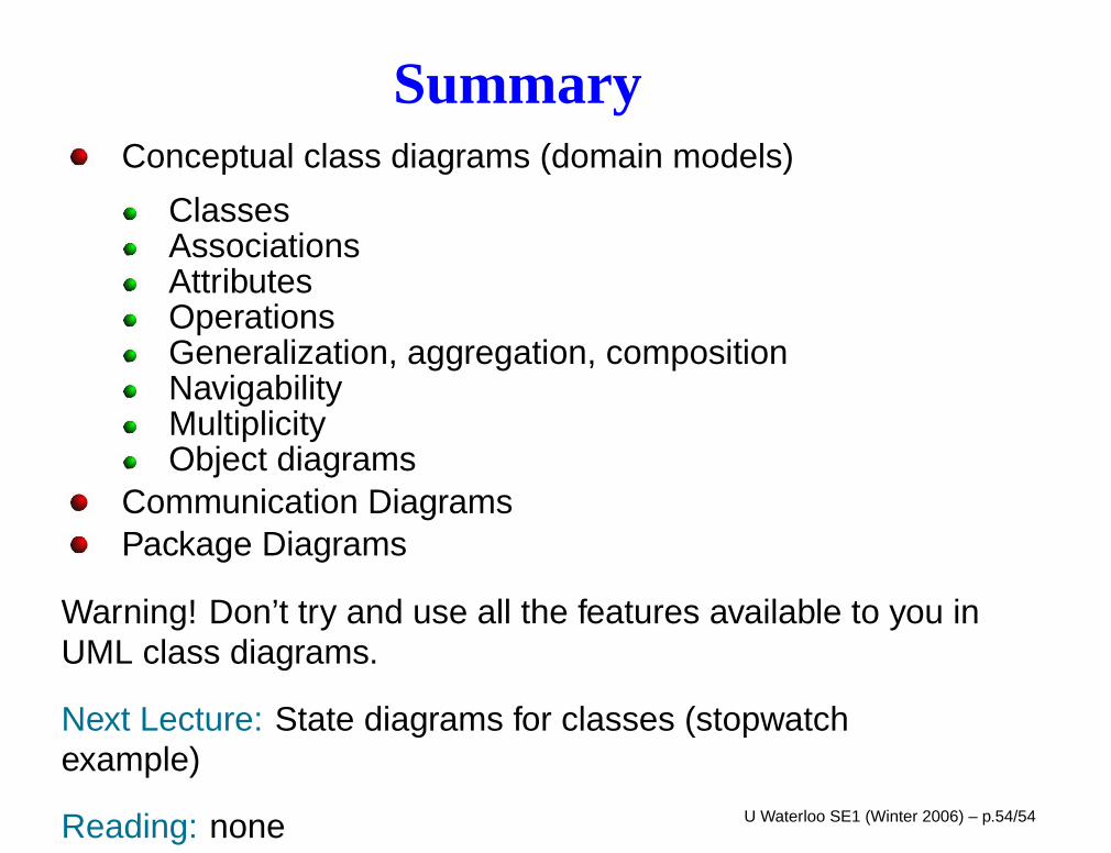
SummaryConceptual class diagrams (domain models)
ClassesAssociationsAttributesOperationsGeneralization, aggregation, compositionNavigabilityMultiplicityObject diagrams
Communication DiagramsPackage Diagrams
Warning! Don’t try and use all the features available to you inUML class diagrams.
Next Lecture: State diagrams for classes (stopwatchexample)
Reading: none U Waterloo SE1 (Winter 2006) – p.54/54