Embed Size (px)
Citation preview

1
DECREE OF THE MINISTER OF COMMUNICATION AND INFORMATION TECHNOLOGY OF THE REPUBLIC OF INDONESIA
NUMBER 34 YEAR 2015
ON
TECHNICAL REQUIREMENTS OF RADIO COMMUNICATION EQUIPMENT OF POINT-TO-POINT MICROWAVE LINK WITH DIGITAL HYBRID SYSTEM
BY THE GRACE OF GOD THE ALMIGHTY
MINISTER OF COMMUNICATION AND INFORMATION TECHNOLOGY OF THE REPUBLIC OF INDONESIA
Considering: a. that in accordance with the provision of Article 71 paragraph (1) of the Government Regulation of the Republic of Indonesia Number 52 Year 2000 on Telecommunication Provision, any telecommunication tool and equipment manufactured, assembled, imported for trade and / or used in the territory of the Republic of Indonesia shall fulfil the technical requirements;
` b. that based on consideration referred to in letter a, it is deemed necessary to issue a Decree of the Minister of Communication and Information Technology on Technical Requirements of Radio Communication Equipment of Point-to-Point Microwave Link Digital With Digital Hybrid System
Bearing in mind: 1. Law of the Republic of Indonesia Number 36 Year 1999 on
Telecommunication (State Gazette of the Republic of Indonesia Number 154 Year 1999, Supplement to the State Gazette of the Republic of Indonesia Number 3881);
2. Law of the Republic of Indonesia Number 39 Year 2008 on State Ministries of the Republic of Indonesia (State Gazette of the Republic of Indonesia Number 166 Year 2008, Supplement to the State Gazette of the Republic of Indonesia Number 4916);
In case the English translation gives rise to different interpretation, please refer to theoriginal version in Indonesian language

2
3. Law of the Republic of Indonesia Number 30 Year 2014 on Governmental Administration (State Gazette of the Republic of Indonesia Number 292 Year 2014, Supplement to the State Gazette of the Republic of Indonesia Number 5601);
4. Government Regulation of the Republic of Indonesia Number 52 Year 2000 on Provision of Telecommunication (State Gazette of the Republic of Indonesia Number 107 Year 2000, Supplement to the State Gazette of the Republic of Indonesia Number 3980);
5. Government Regulation of the Republic of Indonesia Number 53 Year 2000 on Use of Radio Frequency Spectrum and Satellite Orbit (State Gazette of the Republic of Indonesia Number 108 Year 2000, Supplement to the State Gazette of the Republic of Indonesia Number 3981);
6. Decree of the President of the Republic of Indonesia Number 54 Year 2015 on Ministry of Communication and Information Technology;
7.. Decree of the Minister of Communication and Information Technology Number 17/PER/M.KOMINFO/10/2010 on Organization and Work Method of the Ministry of Communication and Information Technology;;
8. Decree of the Minister of Communication and Information Technology Number 5 Year 2013 Group of Telelcommunication Tools and Equipment;
9. Decree of the Minister of Communication and Information Technology Number 18 Year 2014 on Certification of Telecommunication Tools and Equipment as amended by the Decree of the Minister of Communication and Information Technology Number 1 Year 2015 on Amendment to the Decree of the Minister of Communication and Information Technology Number 18 Year 2014 on Certification of Telecommunication Tools and Equipment;
10.Decree of the Minister of Communication and Information Technology Number 25 Year 2014 on Table of Allocation of Radio Frequency Spectrum;
11.Decree of the Minister of Communication and Information Technology Number 15 Year 2015 on Guideline for the
In case the English translation gives rise to different interpretation, please refer to theoriginal version in Indonesian language

3
Composition of Technical Requirements of Tele communication Tools and Equipment;
12.Decree of the Minister of Communication and Information Technology Number 33 Year 2015 on Planning of the Use of Radio Frequency Band of Point-to-Point Microwave Link. .
DECIDES :
To issue : DECREE OF THE MINISTER OF COMMUNICATION AND INFORMATION TECHNOLOGY ON TECHNICAL REQUIREMENTS OF RADIO COMMUNICATION EQUIPMENT OF POINT-TO-POINT MICROWAVE LINK WITH DIGITAL HYBRID SYSTEM
Article 1
Any Radio Communication equipment of Point-to-Point Digital Microwave Link With Digital Hybrid System manufactured, assembled, imported for trade and / or used in the Territory of the Republic of Indonesia shall fulfil the technical requirements as included in the Attachment which is an inseparable part of this Ministerial Decree.
Article 2
Evaluation of the conformance of h obligation of any Radio Communication equipment of Point-To-Point Microwave Link with Digital Hybrid System referred to in Article 1 is conducted in accordance with the provision of legal regulation.
Article 3
This Ministerial Decree shall come into force on the date of its promulgation.
In order to make known to every body, instruct the Promulgation of this Ministerial Decree by placing it in the State Announcement of the Republic of Indonesia. Done at: JAKARTA On : 31 December 2015 ______________________
In case the English translation gives rise to different interpretation, please refer to theoriginal version in Indonesian language

4
MINISTER OF COMMUNICATION AND INFORMATION TECHNOLOGY OF THE REPUBLIC OF INDONESIA,
Signed
RUDIANTARA
Promulgated at Jakartaon 31 December 2015
DIRECTOR GENERAL OF LEGAL AFFAIRSOF THE MINISTRY OF LAW AND HUMANRIGHTS OF THE REPUBLIC OF INDONESKIA
Signed
WIDODO EKATJAHJANA
STATE ANNOUNCEMENT OF THE PUBLIC OF INDONESIA YEAR 2015 NUMBER 2041……….For copy conform to the originalMinistry of Communication and Information Technology
Head of Bureau of Legal Affairs, Signed
Bertiana Sari
In case the English translation gives rise to different interpretation, please refer to theoriginal version in Indonesian language

5
ATTACHMENT
DECREE OF THE MINISTER OF COMMUNICATION AND INFORMATION TECHNOLOGY OF THE REPUBLIC OF INDONESIA NUMBER 34 YEAR 2015ONTECHNICAL REQUIREMENTS OF RADIO COMMUNICATION EQUIPMENT OF POINT-TO-POINT MICROWAVE LINK WITH DIGITAL HYBRID SYSTEM
TECHNICAL REQUIREMENTS OF RADIO COMMUNICATION EQUIPMENT OF POINT-TO-POINT MICROWAVE LINK WITH DIGITAL HYBRID SYSTEM
Technical requirements of Radio Communication equipment of Point-To-Point Microwave Link with Digital Hybrid System cover:
CHAPTER I : General Provisions;CHAPTER II : Technical Requirements;CHAPTER III : Testing.
CHAPTER IGENERAL PROVISIONS
A. Scope
Radio Communication Equipment of Point-To-Point Microwave Link with Digital Hybrid System in this Ministerial Decree covers the equipment of:
1. Microwave Link; and2. Studio to Transmitter Link for the purpose of providing broadcast television;with Digital Hybrid System.
B. Definition
In this Ministerial Decree what is meant by:
1. Radio Communication Equipment of Point-To-Point Microwave Link with Digital Hybrid System is radio communication equipment that has the function to transmit information from one station / point to station / other point (point to point), used at transmission link system to channel baseband signal in the
In case the English translation gives rise to different interpretation, please refer to theoriginal version in Indonesian language
6
form of Ethernet (IP) and Plesiochronous Digital Hierarchy (PDH), Synchronous Digital Hierarchy (SDH), or Asynchronous Transfer Mode (ATM).
2. Point-to-Point Radio Communication is communication provided by a link of a station /point to a station / other point.
3. Microwave Link is point-to-point radio communication system through micro wave which, among other things, is used at telecommunication backbone system, and transmission link, nd has the function of transmitting information from a station / pint to station / other point (point-to-point).
4. Telecommunication Backbone is terrestrial radio communication used for big capacity (SDH STM-1).
5. Transmission Link is terrestrial radio communication used for small and medium capacity.
6. Studio Transmitter Link is point-to-point communication that links broadcasting station (studio) fro a broadcasting institution to transmitter means and / or transmitter means to channel broadcast.
7. Spurious Emission is radio wave emission outside determined bandwidth.
8. Antenna is radio sub equipment that functions to transmit or receive a radio frequency signal.
9. Jitter is variation within a short period which is not a significant instant cumulative of a digital signal from its ideal position at a time scale.
C. Abbreviations
1. ATM : Asynchronous Transfer Mode2. BER : Bit Error Rate3. CBR : Constant Bit Rate4. CS : Channel Separation5. dB : Decibel6. dBm : Decibel milli7. EWS : Engineering Work Station8. GE : Gigabit Ethernet 9. GUI : Graphical User Interface10. HDB3 : High Density Bipolar 311. IDU : Indoor Unit
In case the English translation gives rise to different interpretation, please refer to theoriginal version in Indonesian language

7
12. IP : Internet Protocol13. ODU : Outdoor Unit14. PDH : Plesiochronous Digital Hierarchy15. PSK : Phase-Shift Keying16. QAM : Quadrature amplitude modulation 17. QPSK : Quadrature Phase-Shift Keying18. RIC : Radio Interface Capacities19. RSL : Receive Input Signal Level20. SDH : Synchronous Digital Hierarchy21. STM : Synchronous Transport Module22. TDM : Time-Division Multiplexing 23. UBR : Unspecified Bit Rate 24. VBR-rt : Variable Bit Rate - real time
CHAPTER IITECHNICAL REQUIREMENTS
A. CONFIGURATION
Figure 1. Simple Configuration of Point-To-Point Radio Communication Equipment Via Microwave with Digital Hybrid System
B. FUNCTION OF EQUIPMENT
Radio Communication Equipment of Point-To-Point Microwave Link with Digital Hybrid System must fulfil the operational function as follows:
In case the English translation gives rise to different interpretation, please refer to theoriginal version in Indonesian language

8
1. Adaptive Modulation or Static Modulation;
2. Selectable Channel Bandwidth;
3. Capacity upgradeable by using software;
4. Automatic protection switch for radio system (optional);
5. TDM/IP/ATM interface susceptible to configuration (TDM/IP/ATM interface that can be configurational); and
6. Automatic transmitter power control.
C. MAIN CHARACTERISTIC
1. Radio Frequency
Radio Communication Equipment of Point-to-Point Microwave Link with Digital Hybrid System can only be operated at radio frequency range defined in Table 1
.Explanation on Table 1 below:
a. Frequency Range refers to ITU-R recommendation of F series b. Allocation and frequency are defined in accordance with Table of Allocation
of Radio Frequency Spectrum of Indonesia;c. Channel Space / bandwidth refer to the provision of legal regulation concerning
Planning of the Use of Radio Frequency Band of Point-To-Point Microwave Link.
.:
-
In case the English translation gives rise to different interpretation, please refer to theoriginal version in Indonesian language

9
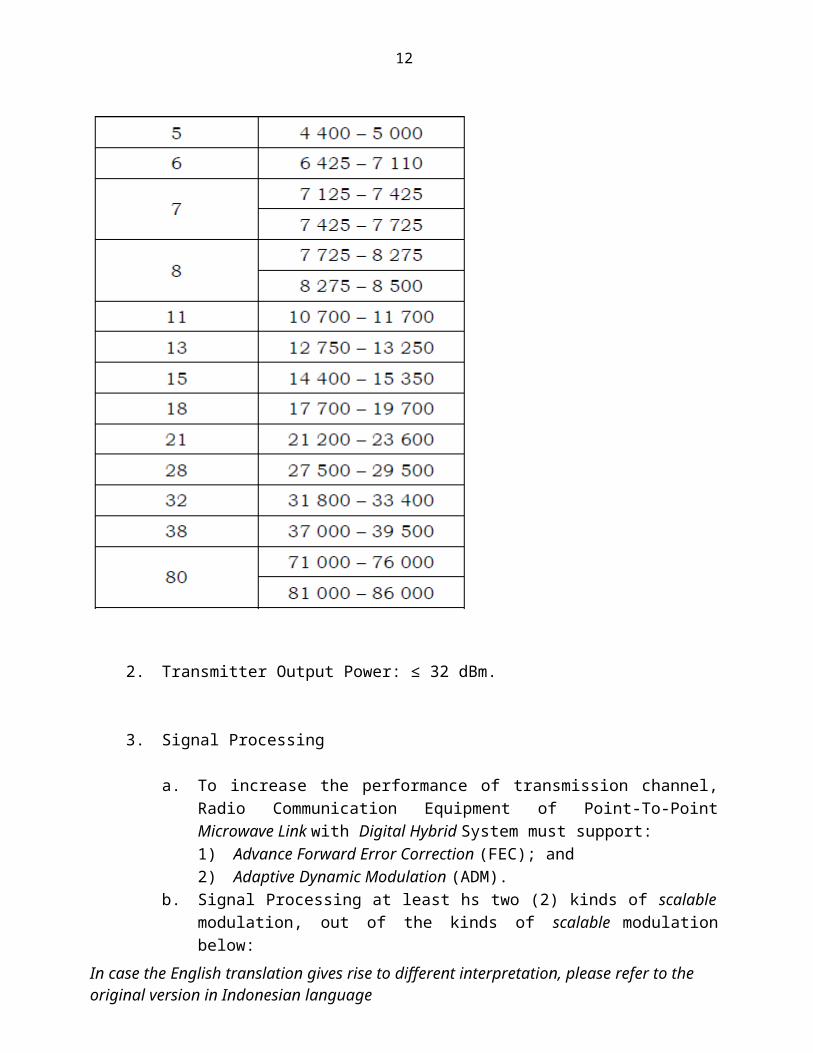
Table 1. Radio Frequency Range for using Radio Communication Equipment of Point-to-Point Microwave Link with Digital Hybrid System
Radio Frequency RangeBand (GHz) Frequency Span
(MHz)
2. Transmitter Output Power: ≤ 32 dBm.
3. Signal Processing
a. To increase the performance of transmission channel, Radio Communication Equipment of Point-To-Point Microwave Link with Digital Hybrid System must support:1) Advance Forward Error Correction (FEC); and2) Adaptive Dynamic Modulation (ADM).
In case the English translation gives rise to different interpretation, please refer to theoriginal version in Indonesian language

10
b. Signal Processing at least hs two (2) kinds of scalable modulation, out of the kinds of scalable modulation below:
1) QPSK;2) 8 PSK;3) 16 QAM;4) 32 QAM;5) 64 QAM;6) 128 QAM;7) 256 QAM;8) 1024 QAM; and / or9) 2048 QAM.
4. Radio Frequency Spectrum Mask
Radio frequency spectrum mask of Radio Communication Equipment of Point-To-Point Microwave Link with Digital Hybrid System refers to standard of ETSI 302 217-2-2, with spectral limitation in accordance with the respective bandwidths / channel space as explained in the following table and figure:
a. Table of Spectral Limitation 1) Spectrum mask of radio frequency for bandwidth / channel space of
1.75 MHz.
Table 2. Spectrum Mask of Radio Frequency for Bandwidth / channel space of 1.75 MHz
Spectral efficiencyClass
Min.RICRate(Mbit/s)
Referenceof MaskingForm
K1(dB)
f1(MHz)
K2(dB)
f2(MHz)
K3(dB)
f3(MHz)
K4(dB)
f4(MHz)
K5(dB)
f5(MHz)
K6(dB)
f6(MHz)
1 1
Figure2
1 0.85 -23 1.05 -23 1.7 -45 32 2
3 3
4L 4 Figure3 1 0.8 -28 1.1
-55(1)
3.5(1)
-5
0(2)
3.1(2)
-4
5(3)
2.6(3)
In case the English translation gives rise to different interpretation, please refer to theoriginal version in Indonesian language

11
(1) For equipment that has frequency range of 3 GHz - 17 GHz. Additionally, for equipment that has frequency range below 10 GHz, there exists other spectrum mask selection where its spectrum mask floor is added with - 60 dB.
(2) For equipment that has frequency range of 17 GHz - 30 GHz.(3) For equipment that has frequency range above 30 GHz.
Spectral efficiencyClass
Min.RICRate(Mbit/s)
Referenceof MaskingForm
Variation of Frequency Corner for - 60 dB floor
4L 4 Figure3
K3 / f3 = -60 dB / 4 MHz
2) Spectrum Mask of radio frequency for bandwidth / channel space of 3.5 MHz.
Table 3. Spectrum Mask of Radio Frequency for Bandwidth /Channel Space of 3.5 MHz
Spectral efficiencyClass
Min.RICRate(Mbit/s)
Referenceof MaskingForm
K1(dB)
f1(MHz)
K2(dB)
f2(MHz)
K3(dB)
f3(MHz)
K4(dB)
f4(MHz)
K5(dB)
f5(MHz)
K6(dB)
f6(MHz)
1 2
Figure2
1 1.7 -23 2.1 -23 3.4 -45 62 4
3 6
4L 8 Figure3 1 1.6 -28 2.2
-55(1) 7(1)
-50(2 6.2(2)
45(3 5.2(3)
(1) For equipment that has frequency range of 3 GHz - 17 GHz. Additionally, for equipment that has frequency range below 10 GHz, there exists other spectrum mask selection where its spectrum mask floor is added with - 60 dB.
(2) For equipment that has frequency range of 17 GHz - 30 GHz.(3) For equipment that has frequency range above 30 GHz.
Spectral efficiencyClass
Min.RICRate(Mbit/s)
Referenceof MaskingForm
Variation of Frequency Corner for - 60 dB floor
4L 8 Figure3
K3 / f3 = -60 dB / 8 MHz
In case the English translation gives rise to different interpretation, please refer to theoriginal version in Indonesian language
12
3) Spectrum Mask of radio frequency for bandwidth / channel space of 7 MHz.
Table 4. Spectrum Mask of Radio Frequency for Bandwidth /Channel Space of 7 MHz
Spectral efficiencyClass
Min.RICRate(Mbit/s)
Referenceof MaskingForm
K1(dB)
f1(MHz)
K2(dB)
f2(MHz)
K3(dB)
f3(MHz)
K4(dB)
f4(MHz)
K5(dB)
f5(MHz)
K6(dB)
f6(MHz)
1 4Figure
2 13.4
-23 4.2 -23 6.8 -45 122 83 12
4L 16 Figure3
1 3.2 -28 4.4 -55(1) 14(1)
-50(2)
12.4(2)
-45(3)
10.4(3)
4H 24 Figure4
1 3 -10 3.75 -33 4.2 -40 8.75
-55(1)
-50(2)
-45(3)13.75(1)
12.075(2)
10.425(3)
5L 29(ACCP)
Figure6
1 3 -10 3.625 -32 3.875 -36 4.25 -45 10 -55(1) 13.5(1)
5H 34(ACCP)
-50(2) 11.75(2)
6L 39(ACCP)
-45(3) 10(3)(4)
(1) For equipment that has frequency range of 3 GHz - 17 GHz. Additionally, for equipment that has frequency range below 10 GHz, there exists other spectrum mask selection where its spectrum mask floor is added with - 60 dB.
(2) For equipment that has frequency range of 17 GHz - 30 GHz.(3) For equipment that has frequency range above 30 GHz. (4) For equipment that has frequency range above 30 GHz. corner points 5 and 6Min.RICRate(Mbit/s)
Min.RICRate(Mbit/s)
Referenceof MaskingForm
Variation of Frequency Corner for - 60 dB floor
4L 16 Figure3
K3 / f3 = -60 dB / 16 MHz
4H 24 Figure4
K5 / f5 = -60 dB / 15.425 MHz
5L, 5H,6L
29, 34, and 39(ACCP)
Figure6 K6 / f6 = -60 dB / 15.25 MHz
In case the English translation gives rise to different interpretation, please refer to theoriginal version in Indonesian language

13
4) Spectrum Mask of Radio Frequency for Bandwidth / Channel Space of 13.75 MHz - 15 MHz (nominal 14 MHz).
Table 5. Spectrum Mask of Radio Frequency for Bandwidth /Channel Space of 13.75 MHz - 15 MHz (nominal 14 MHz)
Spectral efficiencyClass
Min.RICRate(Mbit/s)
Referenceof MaskingForm
K1(dB)
f1(MHz)
K2(dB)
f2(MHz)
K3(dB)
f3(MHz)
K4(dB)
f4(MHz)
K5(dB)
f5(MHz)
K6(dB)
f6(MHz)
1 8 Figure2 1 6.8 -23 8.4 -23 13.6 -45 24
2 16
3 24
4L 32 Figure3
1 1.6 -28 2.2 -55(1) 7(1)
-50(2)
6.2(2)
-45(3)
5.2(3)
4H 49 Figure4
1 6 -10 7.5 -33 8.4 -40 17.5 -55(1)
-50(2)
-45(3)
27.5(1)
24.15(2)
20.85(3)
5L 58(ACCP)
Figure6
1 6 -10 7.25 -32 7.75 -36 8.5 -45 20 -55(1)
-50(2)
-45(3)
27(1)
23.5(2))
20(3)(4)
5H 68(ACCP)
6L 78(ACCP)
6H 88(ACCP)
7 98(ACCP)
8 107(ACCP)
(1) For equipment that has frequency range of 3 GHz - 17 GHz. Additionally, for equipment that has frequency range below 10 GHz, there exists other spectrum mask selection where its spectrum mask floor is added with - 60 dB.
(2) For equipment that has frequency range of 17 GHz - 30 GHz and for 8B class from 17 GHz up to 43.5 GHz. .(3) For equipment that has frequency range above 30 GHz.
In case the English translation gives rise to different interpretation, please refer to theoriginal version in Indonesian language

14
(4) For equipment that has frequency range above 30 GHz. corner points 5 and 6Spectral efficiencyClass
Min.RICRate(Mbit/s)
Referenceof MaskingForm
Variation of Frequency Corner for - 60 dB floor
4L 32 Figure3
K3/f3 = -60 dB / 32 MHz
4H 49 Figure4
K5/f5 = -60 dB / 30.85 MHz
5L, 5H, 6L, 6H,
7, 8
58, 68, 78, 88, 98, and
107(ACCP
)
Figure6 K6/f6 = -60 dB / 30.5 MHz
5) Spectrum Mask of Radio Frequency for Bandwidth / Channel Space of 27.5 MHz - 30 MHz (nominal 28 MHz).
Table 6. Spectrum Mask of Radio Frequency for Bandwidth / Channel Space of 27.5 MHz - 30 MHz (nominal 28 MHz)
Spectral efficiencyClass
Min.RICRate(Mbit/s)
Referenceof MaskingForm
K1(dB)
f1(MHz)
K2(dB)
f2(MHz)
K3(dB)
f3(MHz)
K4(dB)
f4(MHz)
K5(dB)
f5(MHz)
K6(dB)
f6(MHz)
1 16 Figure2 2 12.8 -23 16.4 -23 25 -45 45
2 32
3 48
4L 64 Figure3
2 12.8 -27 27 -55(1) 56(1)
-50(2)
49(2)
-45(3)
42(3)
4H 98 Figure4
2 12 -10 15 -33 16.8 -40 35 -55(1)
-50(2)
-45(3)
55(1)
48.3(2)
41.7(3)
5LA 117(ACAP)
Figure 5
2 12.5 -10. 15 -32 17 -35 20 -45 40
5HA 137(ACAP)
6LA 156(ACAP)
In case the English translation gives rise to different interpretation, please refer to theoriginal version in Indonesian language

15
-55(1)
-50(2)
-45(3)
54(1)
47(2))
40(3)(4)
6HA 176(ACAP)
7A 196(ACAP)
8A 215(ACAP)
5LB 117
(ACCP)
Figure6
2 12 -10. 14.5 -32 15.5 -36 17 -45 40
5HB 137(ACCP)
6LB 156(ACCP)
6HB 176(ACCP)
7B 196(ACCP)
8B 215(ACCP)
(1) For equipment that has frequency range of 3 GHz - 17 GHz. Additionally, for equipment that has frequency range below 10 GHz, there exists other spectrum mask selection where its spectrum mask floor is added with - 60 dB.
(2) For equipment that has frequency range of 17 GHz - 30 GHz and for 8A class and 8B class from 17 GHz up to 43.5 GHz. .(3) For equipment that has frequency range above 30 GHz. (4) For equipment that has frequency range above 30 GHz. corner points 5 and 6Spectral efficiencyClass
Min.RICRate(Mbit/s)
Referenceof MaskingForm
Variation of Frequency Corner for - 60 dB floor
4L 64 Figure3
K3/f3 = -60 dB / 63 MHz
4H 98 Figure4
K5/f5 = -60 dB / 61.7 MHz
5LA,5HA,6LA,’6HA, 7A, 8A
117,137,156,176,196,215
(ACAP)
Figure5
K6/f6 = -60 dB / 61 MHz
5LB,5HB,6LB,
117,137,156,
Figure6
K6/f6 = -60 dB / 61 MHz
In case the English translation gives rise to different interpretation, please refer to theoriginal version in Indonesian language

16
6HB, 7B, 8B ,
176,196,215
(ACCP)
6) Spectrum Mask of Radio Frequency for Bandwidth / Channel Space of 40 MHz.
Table 7. Spectrum Mask of Radio Frequency for Bandwidth / Channel Space of 40 MHz
Spectral efficiencyClass
Min.RICRate(Mbit/s)
Referenceof MaskingForm
K1(dB)
f1(MHz)
K2(dB)
f2(MHz)
K3(dB)
f3(MHz)
K4(dB)
f4(MHz)
K5(dB)
f5(MHz)
K6(dB)
f6(MHz)
5LA 168(ACAP)
Figure 5
2 18 -10. 21.5 -32 24.5 -35 29 -45 57
-55(1)
-77(1)
5HA 196(ACAP)
6LA 224(ACAP)
6HA 252(ACAP)
7A 280(ACAP)
8A 308(ACAP)
5LB 168
(ACCP)
Figure6
2 17.2 -10. 20.8 -32 22.5 -36 24.5 -45 57
5HB 196(ACCP)
6LB 224(ACCP)
6HB 252(ACCP)
In case the English translation gives rise to different interpretation, please refer to theoriginal version in Indonesian language

17
7B
8B
280(ACCP)
308(ACCP)
(1) For all equipment of frequency range. Additionally, for equipment that has frequency range below 10 GHz, there exists other spectrum mask selection where its spectrum mask floor is added with - 60 dB.
Note: equipment using bandwidth or channel space of 40 MHz is generally high capacity connection. Hence at this table, spectral efficiency class starts from 5A class.Spectral efficiencyClass
Min.RICRate(Mbit/s)
Referenceof MaskingForm
Variation of Frequency Corner for - 60 dB floor
5LA, 5HA,6LA,’6HA, 7A, 8A
168,196,224,252,280,308
(ACAP)
Figure 5
K6/f6 = -60 dB / 87 MHz
5LB, 5HB, 6LB, 6HB, 7B, 8B
168,196,224,252,280,308
(ACCP)
Figure 6
K6/f6 = -60 dB / 87 MHz
7) Spectrum Mask of Radio Frequency for Bandwidth / Channel Space
of 55 MHz - 60 MHz (nominal 56 MHz)
.Table 8. Spectrum Mask of Radio Frequency for Bandwidth / Channel Space of 55 MHz - 60 MHz (nominal 56 MHz)
Spectral efficiencyClass
Min.RICRate(Mbit/s)
Referenceof MaskingForm
K1(dB)
f1(MHz)
K2(dB)
f2(MHz)
K3(dB)
f3(MHz)
K4(dB)
f4(MHz)
K5(dB)
f5(MHz)
K6(dB)
f6(MHz)
1 32 Figure2 2 25.6 -23 32.8 -23 50 -45 90
2 64
3 96
4L 128 Figure3
2 25.6 -27 34 -55(1) 112(1)
-50(2)
98(2)
-45(3) 84(3)
In case the English translation gives rise to different interpretation, please refer to theoriginal version in Indonesian language

18
4H 196 Figure4
2 24 -10 30 -33 33.6 -40 70 -55(1)
-50(2)
-45(3)
110(1)
96.6(2)
83.4(3)
5LA 235(ACAP)
Figure 5 2 25 -10. 30 -32 34 -35 40 -45 80
-55(1)
-50(2)
-45(3)
108(1)
94(2)
80(3)(4)
5HA 274(ACAP)
6LA 313(ACAP)
6HA 352(ACAP)
7A 392(ACAP)
8A 431(ACAP)
5LB 235
(ACCP)Figure
6 2 24 -10. 29 -32 31 -36 34 -45 805HB 274
(ACCP)
6LB 313(ACCP)
6HB 352(ACCP)
7B 392(ACCP)
8B 431(ACCP)
In case the English translation gives rise to different interpretation, please refer to theoriginal version in Indonesian language

19
(1) For equipment that has frequency range of 3 GHz - 17 GHz. Additionally, for equipment that has frequency range below 10 GHz, there exists other spectrum mask selection where its spectrum mask floor is added with - 60 dB.
(2) For equipment that has frequency range of 17 GHz - 30 GHz and for 8A class and 8B class from 17 GHz up to 43.5 GHz. .(3) For equipment that has frequency range above 30 GHz. (4) For equipment that has frequency range above 30 GHz. corner points 5 and 6Spectral efficiencyClass
Min.RICRate(Mbit/s)
Referenceof MaskingForm
Variation of Frequency Corner for - 60 dB floor
4L 128Figure
3
K3/f3 = -60 dB / 126.0 MHz
4H 196Figure
4 K5/f5 = -60 dB / 123.4 MHz
5LA, 5HA,6LA,’6HA, 7A, 8A
235,274,313,352,392,431
(ACAP)
Figure5 K6/f6 = -60 dB / 122 MHz
5LB, 5HB, 6LB, 6HB, 7B, 8B
235,274,313,352,392,431
(ACCP)
Figure6 K6/f6 = -60 dB / 122 MHz
8) Spectrum Mask of Radio Frequency for Bandwidth / Channel Space of 112 MHz.
Table 9. Spectrum Mask of Radio Frequency for Bandwidth / Channel Space of 112 MHz
Spectral efficiencyClass
Min.RICRate(Mbit/s)
Referenceof MaskingForm
K1(dB)
f1(MHz)
K2(dB)
f2(MHz)
K3(dB)
f3(MHz)
K4(dB)
f4f4
(MHz)
K5(dB)
f5(MHz)
K6(dB)
f6(MHz)
1 64
Figure2
2 51.2 -23 65.6 -23 100 -45 1802 128
3 191
4L 256 Figure3
2 51.2 -27 68-55(1)
196(1)
45(2))
-
168(2)
In case the English translation gives rise to different interpretation, please refer to theoriginal version in Indonesian language

20
4H 392 Figure4
2 48 -10 60 -33 67.2 -40 140 -55(1)
-45(3)193.2(1)
166.8(3)
5LA 470(ACAP)
Figure 5 2 50 -10. 60 -32 68 -35 80 -45 160
-55(1)
45(2)(3)188(1)
160(2)(3))
5HA 548(ACAP)
6LA 627(ACAP)
6HA 705(ACAP)
7A 784(ACAP)
8A 862(ACAP)
5LB 470
(ACCP)Figure
6 2 24 -10. 29 -32 31 -36 34 -45 805HB 548
(ACCP)
6LB 627(ACCP)
6HB 705(ACCP)
7B 784(ACCP)
8B
862(ACCP)
(1) For equipment that has frequency range of 17 GHz - 30 GHz and for 8A class and 8B class from 17 GHz up to 43.5 GHz
In case the English translation gives rise to different interpretation, please refer to theoriginal version in Indonesian language

21
(2) For equipment that has frequency range above 30 GHz. (3) For equipment that has frequency range above 30 GHz. corner points 5 and 6
9) Spectrum Mask of Radio Frequency for Bandwidth / Channel Space of 125 MHz.
Table 10. Spectrum Mask of Radio Frequency for Bandwidth / Channel Space of 125 MHz
Spectral efficiencyClass
Min.RICRate(Mbit/s)
Referenceof MaskingForm
K1(dB)
f1(MHz)
K2(dB)
f2(MHz)
K3(dB)
f3(MHz)
K4(dB)
f4 (MHz)
K5(dB)
f5(MHz)
171 Figure
73 57.3 -18
-70 -23 112 - 40 181.3 -40 31`2.5
2 1423 212
4L 284 Figure8 3 57.3 - 25 74.5 -40(2) 157 - 40
312.5
4H 438 Figure9 3 55 -10 67 -28 74.5 -43 174 -43 31`2.5
5LA 438Figure
103 55 -10 67
-3175.8 -45
174
-45
31`2.55HA 612 -3477
-45 -45
6LA 700 -37 78.2
-45 -45
5B 438Figure
113 53.5 -10 64.8
-3169
-45
174
-45
31`2.55HB 612 -34
69.5-45 -45
6LB 700 -37 70 -45 -45
10) Spectrum Mask of Radio Frequency for Bandwidth / Channel Space of N x 250 MHz.
.Table 11. Table 10. Spectrum Mask of Radio Frequency for Bandwidth / Channel Space of N x 250 MHz
In case the English translation gives rise to different interpretation, please refer to theoriginal version in Indonesian language

22
Spectral efficiencyClass
Min.RICRate(Mbit/s)
Referenceof MaskingForm
K1(dB)
f1(MHz)
K2(dB)
f2(MHz)
K3(dB)
f3(MHz)
K4(dB)
f4 (MHz)
K5(dB)
f5(MHz)
1 N X 142
Figure7
3 N X 114.5
-18 N X 140
-23 Nx 224
- 40(2)N x
362.5- 40(2)
31`2.5
2 N X 285(7)
3 N X 425(7)
4L N X 570(7) Figure8
3 N X 114.5
- 25 N X 149
-40(2) N x 314 - 40(2) (1)
4H N X 875 Figure9
3N X 110
-10 N X 134
-28 N x 149
-43(3)) Nx 348
-43(3)) (1)
5LA NX1050(7)
Figure10
3
N X 110
-10 N X 134
-31 N x 151
-45(4) Nx 348
-45(4) (1)
5HA N X 1225 -34 N x 154
-45(5)-45(5)
6LA N X 1400 -37 N x 156
-45(6) -45(6)
5LB NX1050(7)
Figure11
3
N X 107 -10
N X 129.5
-31 N x 138
-45(4) Nx 348
-45(4)
(1)
5HB N X 1225 -34N x 139 -45(5)
-45(5)
6LB N X 1400 -37Nx140 -45(6)
-45(6)
(1) For equipment that has bandwidth / channel space of ≤500 MHz, the value of CS x 2.5 bandwidth / channel space is ≥500 MHz, the value of CS x 1.5 + 500.(2) For equipment that has attenuation less than -40 + log (N) is not compulsory.(3) For equipment that has attenuation less than -43 + log (N) is not compulsory.(4) As for N ≥ 2, for equipment that has attenuation less than -46 log (N) is not compulsory.(5) As for N ≥ 3, for equipment that has attenuation less than -49 + log (N) is not compulsory.(6) As for N ≥ 6, for equipment that has attenuation less than -52 + log (N) is not compulsory.(7) For class 2 (N=4), class 3 (N=5), class 4 (N=2 and N=4), class 5LA and 5LB (N= 1, 2, 3), the minimum of RIC the
value of which approaches 1 Gbit / s is also considered valid.NOTE 1 : N may vary from 1 up to 8, vde annex Ea for more detail.NOTE 2 : 10 log (N) is meant for eliminating the first decimal value.
In case the English translation gives rise to different interpretation, please refer to theoriginal version in Indonesian language

23
b. Reference Figure of Spectrum Mask Form
The following Figure shows a typical curve form and format which represent the above table of Spectrum Mask.
For all spectrum masks, the upper limit of radio frequency spectrum is 2.5 x CS. Hereafter is the Figure of Radio frequency spectrum mask in conformance with the Segment.
1) Reference of Spectrum Mask Form for Spectral Efficiency Class 1, 2, and 3 (Radio Frequency Range below 57 GHz)..
Figure 2. Reference of Spectrum Mask Form for Spectral Efficiency Class 1, 2, and 3 (Radio Frequency Range below 57 GHz).
2) Reference of Spectrum Mask Form for Spectral Efficiency Class 4L (Radio Frequency Range below 57 GHz).
In case the English translation gives rise to different interpretation, please refer to theoriginal version in Indonesian language

24
.. Figure 3. Reference of Spectrum Mask Form for Spectral Efficiency Class 4L (Radio Frequency Range below 57 GHz).
3) Reference of Spectrum Mask Form for Spectral Efficiency Class 4H (Radio Frequency Range below 57 GHz).
Figure 4. Reference of Spectrum Mask Form for Spectral Efficiency Class 4H (Radio Frequency Range below 57 GHz).
4) Reference of Spectrum Mask Form for Spectral Efficiency Class 5LA, 5HA, 6LA, 6HA, 7A, 8A (Radio Frequency Range below 57 GHz).
In case the English translation gives rise to different interpretation, please refer to theoriginal version in Indonesian language

25
Figure 5. Reference of Spectrum Mask Form for Spectral Efficiency Class 5LA, 5HA, 6LA, 6 HA,7A, 8A (Radio Frequency Range below 57 GHz).
5) Reference of Spectrum Mask Form for Spectral Efficiency Class 5L, 5H, 6L,6H, 7, 8, 5LB, 5HB, 6LB, 6HB, 7B, 8B (Radio Frequency Range below 57 GHz).
In case the English translation gives rise to different interpretation, please refer to theoriginal version in Indonesian language

26
Figure 6. Reference of Spectrum Mask Form for Spectral Efficiency Class 5L, 5H, 6L, 6 H,7, 8, 5LB, 5HB, 6LB, 6HB, 7B, 8B (Radio Frequency Range below 57 GHz).
6) Reference of Spectrum Mask Form for Spectral Efficiency Class 1, 2 and 3 (Radio Frequency Range of 71 GHz - 76 GHz and 81 GHz - 86 GHz)
. Figure 7. Reference of Spectrum Mask Form for Spectral Efficiency Class 1, 2, and 3 (Radio Frequency Range of 71 GHz - 76 GHz and 81 GHz - 86 GHz)
7) Reference of Spectrum Mask Form for Spectral Efficiency Class 4L (Radio Frequency Range of 71 GHz - 76 GHz and 81 GHz - 86 GHz)
In case the English translation gives rise to different interpretation, please refer to theoriginal version in Indonesian language

27
Figure 8. Reference of Spectrum Mask Form for Spectral Efficiency Class 4L (Radio Frequency Range of 71 GHz - 76 GHz and 81 GHz - 86 GHz)
8) Reference of Spectrum Mask Form for Spectral Efficiency Class 4H (Radio Frequency Range of 71 GHz - 76 GHz and 81 GHz - 86 GHz)
Figure 9. Reference of Spectrum Mask Form for Spectral Efficiency Class 4H (Radio Frequency Range of 71 GHz - 76 GHz and 81 GHz - 86 GHz)
In case the English translation gives rise to different interpretation, please refer to theoriginal version in Indonesian language

28
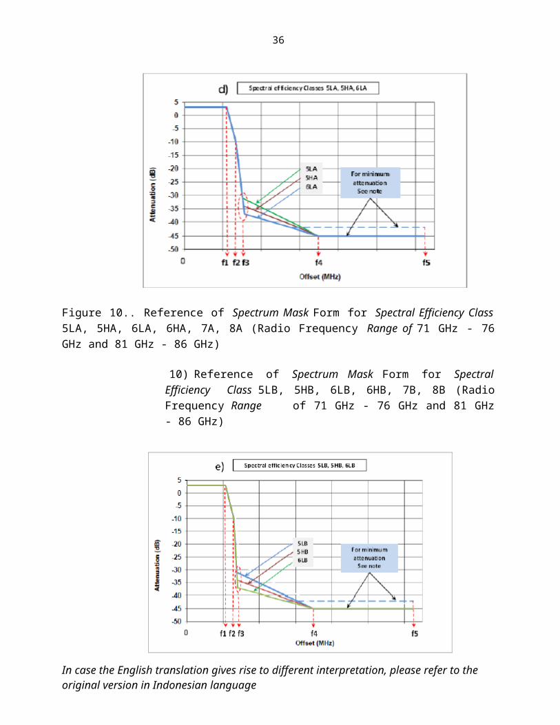
9) Reference of Spectrum Mask Form for Spectral Efficiency Class 5LA, 5HA, 6LA, 6HA, 7A, 8A (Radio Frequency Range of 71 GHz - 76 GHz and 81 GHz - 86 GHz)
Figure 10.. Reference of Spectrum Mask Form for Spectral Efficiency Class 5LA, 5HA, 6LA, 6HA, 7A, 8A (Radio Frequency Range of 71 GHz - 76 GHz and 81 GHz - 86 GHz)
10) Reference of Spectrum Mask Form for Spectral Efficiency
Class 5LB, 5HB, 6LB, 6HB, 7B, 8B (Radio Frequency Range of 71 GHz - 76 GHz and 81 GHz - 86 GHz)
In case the English translation gives rise to different interpretation, please refer to theoriginal version in Indonesian language

29
Figure 11.. Reference of Spectrum Mask Form for Spectral Efficiency Class 5LB, 5HB ,6LB, 6HB, 7B, 8B (Radio Frequency Range of 71 GHz - 76 GHz and 81 GHz - 86 GHz)
5. RSL
a. for Frequency Band of 5 GHz - 11 GHz (Bandwidth / Channel Space of 30 MHz and 56 / 60 MHz)
Table 12. BER as a function of RSL for Frequency Band of 5 GHz (4 400 - 5 000 MHz) - 11 GHz [10 700 - 11 700 MHz] [Bandwidth / Channel Space of 30 MHz and 56 / 60 MHz].
In case the English translation gives rise to different interpretation, please refer to theoriginal version in Indonesian language

30
NOTE: For channel space of 28 MHz 30 MHz or 56 MHz - 60 MHz, the class system of 5LB, 5HB, 6LB, 6HB, 7B and 8B, the above Limit is applicable when using equally good antenna port in even or odd number of channels, with channel space of 30 MHz or 60 MHz, where each of them is separated by the same polarization, arranged using external hybrid coupler of 3dB or using narrow band banching filters. in that condition the value of threshold BER is deducted by 1.5 dB.
b. for Frequency Band of 5 GHz 11 GHz (Bandwidth / Channel Space of
40 MHz).
Table 13. BER as a function of RSL for Frequency Band of 5 GHz (4 400 - 5 000 MHz) - 11 GHz [10 700 - 11 700 MHz) (Bandwidth / Channel Space of 40 MHz)
Note: The above limit is applicable when using equally good antenna port in even and odd number of channels, with channel space of 30 MHz or 60 MHz, where each of them is separated by the same polarization, arranged using external hybrid couple of 3 dB or using narrow band banching filters.In that condition, the value of threshold BER is deducted by 1.5 dB.
c. for Frequency Band of 13 GHz and 15 GHz.
In case the English translation gives rise to different interpretation, please refer to theoriginal version in Indonesian language

31
Table 14. BER as a function of RSL for Frequency Band of 13 GHz (12 750 - 13 250 MHz) and 15 GHz (14 400 -15 350 MHz)
Note: The above limit is applicable when using equally good antenna port in even and odd number of channels with channel space of 30 MHz or 60 MHz, where each of them is separated by the same polarization, arranged using external hybrid coupler of 3 dB or using narrow band banching filters .In that condition the value of threshold BER is deducted by 1.5 dB.
In case the English translation gives rise to different interpretation, please refer to theoriginal version in Indonesian language

32
d. for Frequency Band of 18 GHz
Table 15. BER as a function of RSL for Frequency Band of 18 GHz (17 700 - 19 700 MHz)
In case the English translation gives rise to different interpretation, please refer to theoriginal version in Indonesian language

33
Note: The above limit is applicable when using equally good antenna port in even and odd number of channels , with channel space of 30 MHz or 60 MHz, where each of them is separated by the same polarization, arranged using external hybrid coupler of 3 dB or using narrow band banching filters .In that condition the value of threshold BER is deducted by 1.5 dB.
e. for E System with system for RIC <100 Mbit / s
Table 16. BER as a function of RSL for E System [Radio Frequency of 21 GHz (21 200 - 23 600 MHz), and 26 GHz - 28 GHz (27 500 - 29 500 MHz) with a system for RIC < 100 Mbit / s.
In case the English translation gives rise to different interpretation, please refer to theoriginal version in Indonesian language

34
Table 17. BER as a function of RSL for E System [Radio Frequency of 32 GHz (31 800 - 33 400 MHz) and 38 GHz (37 000 - 39 500 MHz) with a system for RIC < 100 Mbit / s]
In case the English translation gives rise to different interpretation, please refer to theoriginal version in Indonesian language

35
In case the English translation gives rise to different interpretation, please refer to theoriginal version in Indonesian language
36
f. for E System with system for RIC ≥100 Mbit / s
Table 18. BER as a function of RSL for E System [Radio Frequency of 21 GHz (21 200 - 23 600 MHz) and 26 GHz - 28 GHz (27 500 - 29 500 MHz) with a system for RIC ≥ 100 Mbit / s]
In case the English translation gives rise to different interpretation, please refer to theoriginal version in Indonesian language

37
Table 19. BER as a function of RSL for E System [Radio Frequency of 32 GHz (31 800 - 33 400 MHz) and 38 GHz (37 000 - 39 500 MHz) with a system for RIC ≥ 100 Mbit / s]
In case the English translation gives rise to different interpretation, please refer to theoriginal version in Indonesian language

38
g. for Ea System
Table 20. BER as a function of RSL for Ea System [Radio Frequency of 71 GHz (71 000 - 76 000 MHz) up to 80 GHz (81 000 - 86 000 MHz)
In case the English translation gives rise to different interpretation, please refer to theoriginal version in Indonesian language

39
NOTE: RIC is rounded at the multiplication of 1 Gbit / s rate also considered as valid value.
6. Spurious Emission
a. Spurious Power Maximum : -65 dBm / 30 kHzb. Noise floor Maximum : -85 dBm / 30 kHz
7. Physical Interface
Radio Communication Equipment of Point-To-Point Microwave Link with Digital Hybrid System must have:
In case the English translation gives rise to different interpretation, please refer to theoriginal version in Indonesian language

40
a. port interface Ethernet; andb. at least one of the following physical interfaces:
1) Port Interface of 2048 kbps;2) Port Interface of SDH; or3) Port interface of ATM.
With the following technical provisions:
a. Port Interface Ethernet:
1) Capable of providing interface ethernet of 10 / 100 T Base and or 1000 T Base (GE) with the type of RJ45 or GE optical connector;
2) Characteristic of ethernet is in accordance with IEEE 802.3 recommendation;
3) Any data interface has the capability of full-duplex operation, automatic configuration and flow control;
4) Any data interface must be capable of providing service with equalizationminimum latency (less than 10 ms); and
5) Support jumbo frame minimum 1600 bytes (optional).. .
b. Port Interface of 2048 kbps
a. Bit rate : 2048 kbps ± 50 ppm (± 102.4 bps)
b. Code : HDB3
c. Line impedance : 120Ώ (balance)
d. Nominal peak voltage : 3 Vof a “mark”
e. Peak voltage of a “space” : 0 V ± 0.3 V
f. Pulse width : 244 ns ± 25 ns
g. Ratio of the amplitudes of : 0.95 ~ 1.05positive and negativepulses at the centre of thepulse interval
h. Ratio of the widths of : 0.95 ~ 1.05
In case the English translation gives rise to different interpretation, please refer to theoriginal version in Indonesian language

41
positive and negativepulses at the nominalhalf amplitude
i. Line attenuation : ≥ 6 dBequalization
j. Frame structure : 1 frame consists of 32 time slots. Time slot 16 is for signalling and multi frame a lignment word / signal , time slot 0 for alarm and frame alignment signal
k. BER Test : Maximum 1 x 10⁻⁹. Duration 15 minutes
l. Return Loss : In accordance with radio frequency range
. . .
\Table 20. Return Loss 2048 Kbps
Frequency range )kHz) Return Loss (dB)51 up to 102 12
102 up to 2048 182048 up to 3072 14
c. Port Interface of SDH
Interface of SDH using STM-1Electric, STM-1 Optical or STM-4, must fulfil the following requirements:
1) Port Interface 155520kbps (electrical)
2) Bit rate : 155520 kbps ± 20 ppm (± 3111 bps)
3) Code : CMI
4) Line impedance : 5 W resistive (unbalance)
5) Nominal peak-peak voltage : 1 ± 0.1 V
In case the English translation gives rise to different interpretation, please refer to theoriginal version in Indonesian language

42
6) Nominal Pulse width : 6.43 ns
7) The rising time of amplitude : ± 2ns between 10% and 90% measured from fixedamplitude
8) Transition timing tolerance : (refers to maon value 50% of amplitude point from negative transitions).
a) Negative transitions : ± 0.1 ns.
b) Positive transitions : ± 0.5 ns.at interval boundariesunit
c) Positive transitions : ± 0.35 ns.at mid intervalboundaries
9) Return loss at port output : > 15 dB at frequency of 8 MHz up tp 240 MHz.
10) Specifications at port input : Maximum attenuation of channel of 12.7 dB at
frequency of 78 MHz.
11) Return loss : > 15 dB at frequency of 8 MHz up to 240 MHz
d. Port Interface 155520 kbps (optical)
1) Bit rate: 155520 kbps ± 20 ppm (± 3111 bps)2) Maximum requirements for transfer jitter parameter is 0.1 dB.
e. Port Interface 622080 kbps (optical)
1) Bit rate: 622080 kbps ± 20 ppm (± 12442 bps)2) Maximum requirements for transfer jitter parameter is 0.1 dB.
f. Port Interface Optical G
In case the English translation gives rise to different interpretation, please refer to theoriginal version in Indonesian language

43
For usage of Gigabit Ethernet (GE) with optical interface, the characteristic of port must fulfil the requirements in the following table:
Table 21. GE Ethernet Port Interface Requirement
.
g. Port Interface of ATM
Equipment must support the following features:
1) Data encapsulation is compatible with RFC 1483 and RFC 1577..
2) Point to Point Protocol (PPP) is compatible with RFC 2364.3) Adaption layer of AAL2 and AAL5..4) UBR, CBR and VBR-rt.
When an equipment is connected to ATM network, it must have a compatible interface.
8. Control System
Radio Communication Equipment of Point-To-Point Microwave Link with Digital Hybrid System must have the following control and monitoring system:
a. it has local and central management capability planned to be user friendly in using GUI viewer or Web Based;
b. it has back up and restore capability of data configuration;
c. it covers the functions of network management system, at least as indicated hereunder:
In case the English translation gives rise to different interpretation, please refer to theoriginal version in Indonesian language

44
1) Fault alarm Management, alarm monitoring, fault detection and fault localization;
2) Configuration management, network configuration and inventory, configuration and service activation (provisioning);
3) Performance management, performance data, and performance measurement;
4) Security management and user and group access privileges management.
9. Power Supply
a. Capable of receiving volt : (220 ± 10%) Vac / (50 ± 6%) Hz; or
b. Capable of receiving volt : (-48 ± 10%) Vdc.
D. SUPPLEMENTARY CHARACTERISTIC
1 Raw Material
Radio Communication Equipment of Point-To-Point Microwave Link with Digital Hybrid System and its components must be made from strong, solid and high quality material , anti-corrosion anti-condensation.
2. Construction
a. The equipment components must:
1) be neatly and well arranged at Printed Circuit Board/PCB for each module; and
2) be perfect, well isolated, and no jumper is found using cable at Printed Circuit Board/PCB.
b Wiring and cabling requirements
1) wiring and cabling in equipment must be neat and good;
In case the English translation gives rise to different interpretation, please refer to theoriginal version in Indonesian language

45
2) in case integration between cards or modules need wiring and cabling, such wiring and cabling must use plug-in jack system and avoid soldering as far as possible;
3) power supply cable f negative and positive volt must be differentiated and connecting in the equipment must be good and srong.
c. EMC and safety: refer to SNI CISPR 22 and 24 standard.
3. Environmental Condition
Radio Communication Equipment of Point-To-Point Microwave Link with Digital Hybrid System must be able to operate constantly at the following environmental condition:
a. Temperature up to 55oC.
b. Density of 5 up to 95%.
CHAPTER IIITESTING REQUIREMENT
Testing of Radio Communication Equipment of Point-To-Point Microwave Link with Digital Hybrid System is done in accordance with the provision of legal regulation.
MINISTER OF COMMUNICATION AND INFORMATION TECHNOLOGY OF THE REPUBLIC OF INDONESIA
Signed
RUDIANTARA
In case the English translation gives rise to different interpretation, please refer to theoriginal version in Indonesian language


![Grace Theological Joumal12 - Gordon College Faculty · Web viewComposition of the Book of Daniel," VT 4 [1954J: 246-75; M. L. Delcor, Le Livre de Daniel [SB; Paris: Gabalda, 1971]](https://img.pdfslide.us/doc/110x75/5ae26ddc7f8b9a90138c4e10/grace-theological-joumal12-gordon-college-faculty-viewcomposition-of-the-book.jpg)