Embed Size (px)
Citation preview

SDN Controller Design for Dynamic Chaining of Virtual Network Functions.
Franco Callegati, Walter Cerroni, Chiara Contoli, Giuliano Santandrea
Dept. of Electrical, Electronic and Information Engineering University of Bologna – Italy
EWSDN 2015 – September 30, 2015 – Bilbao, Spain

Context
2
• Network programmability is becoming feasible owing to recently developed key technologies o SDN o NFV o hardware capable of supporting them
• NFV as a flexible solution for replacing vendor dependent middle-boxes
• Paradigm shift will take place mainly at the network edges

Core Network
Edge Network Data Center
Edge Network Data Center
Edge Network Data Center
VNF
VNF
VNF VNF VNF VNF
VNF VNF VNF
Data flow f1(t0)
Data flow f2(t0)
Data flow f2(t1)
NFV Chaining & dynamic traffic steering
Space chaining diversity
Time chaining diversity

Goal
• Suggest a design methodology for implementing SDN control plane capable of
o Dynamically steering traffic towards required VNF o Achieving fully adaptive service chaining
• Case study: o Layer 2 (L2) Edge network o OpenStack cloud platform
• What about SDN controller design?
o Mealy Machine abstraction as general approach to service chain reconfiguration
o example: dynamic enforcement of QoS in a multi-tenant scenario
4

SDN controller abstraction
5
• Finite State Machine (FSM) • Formal definitions:
o ƒ: traffic stream o s: set of state
o i: set of input
o A(ƒ,s,i): actions (SDN technology dependent) o T: state transition function
s ∈ {Init,C,E,N,D}
i ∈ {PKT _ IN,SLA_C,SLA_NC,CONG,NO_CONG}
(s, i)→ (s ',A( f , s, i))

States definition
• State definition: o Init: flow independent rules are installed in the network nodes o C: flow ƒ is analyzed and classified o E: flow ƒ is strictly subject to QoS enforcement o N: flow ƒ is not strictly subject to QoS enforcement o D: flow ƒ is subject to policing actions
• Additional parameters can be defined
6

Genaral parameters
• NT = {SW1, SW2, …, SWNSW} set of switch • SWj = {p1, p2, …,pNp,j} set of ports • U = {u1, u2,…, uNu} set of users • NF = {F1, F2, …,FNF} set of VNFs • Ch(f, s) = {Fl1, Fl2, …, Fln(f,s)} service chain of n(f,s) VNFs applied to ƒ
in state s • Getting topology information:
o (SWj,pm) = get_port(uk) o (SWj,pm) = get_in_port(Fl,d) o (SWj,pm) = get_out_port(Fl,d)
• SWj ∈ NT, pm ∈ SWj, uk ∈ U, Fl ∈ NF and d ∈ {inbound, outbound} • flow_mod(SWj, cmd, opts, match, fwdlist)
7

Case study topology: OpenStack platform

Case study definitions
• NT = {SW1, SW2} • U = {BU, RU, DEST} • NF = {DPI, TC, WANA1, WANA2, VR1, VR2} • Service chain definition:
o Ch(ƒBU,Init) = Ch(ƒBU,D) = nill o Ch(ƒBU,C) = {DPI & VR1} o Ch(ƒBU,E) = {WANA1,VR1} o Ch(ƒBU,N) = {VR1}
• What about actions during state transition?

Init state actions
10
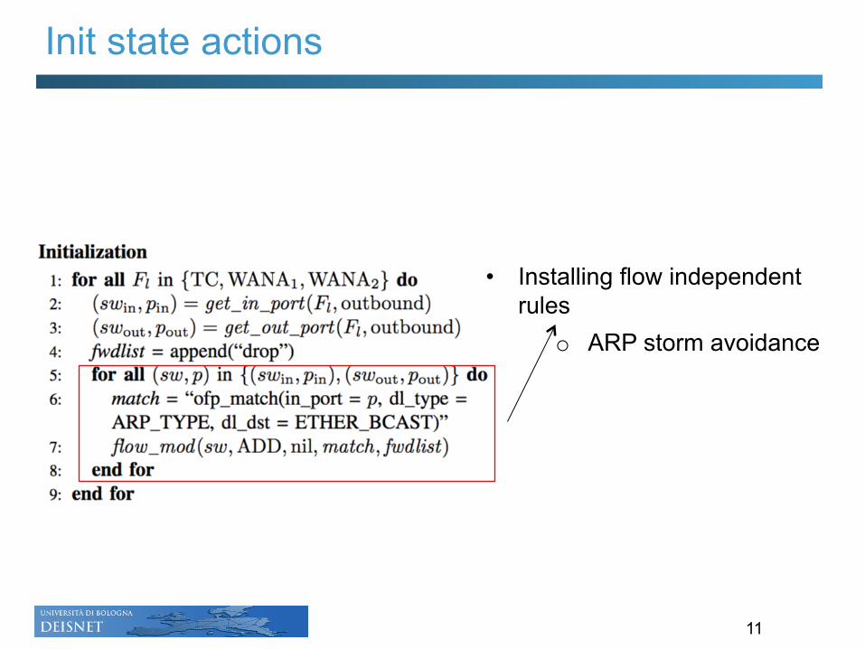
Init state actions
11
• Installing flow independent rules
o ARP storm avoidance

T(Init, PKT_IN) = (C, A(ƒBU,Init,PKT_IN))
12

T(Init, PKT_IN) = (C, A(ƒBU,Init,PKT_IN))
13
Getting topology information

T(Init, PKT_IN) = (C, A(ƒBU,Init,PKT_IN))
14
OpenFlow actions

T(Init, PKT_IN) = (C, A(ƒBU,Init,PKT_IN))
15
Installing rule on the switch

T(Init, PKT_IN) = (C, A(ƒBU,Init,PKT_IN))
16
Handling bidirectional flows
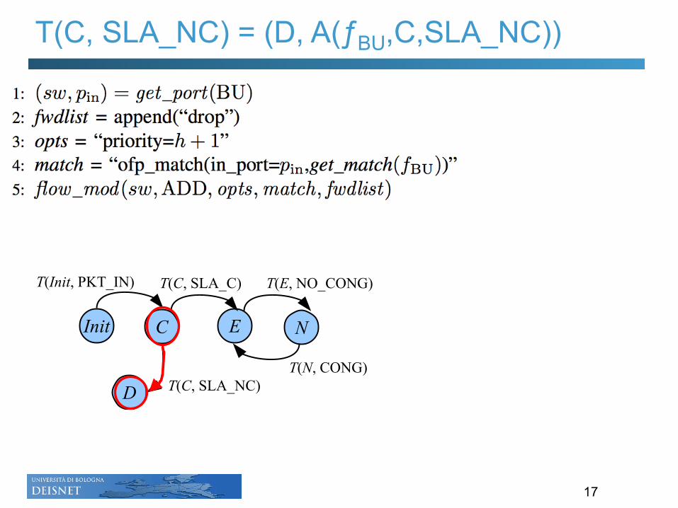
T(C, SLA_NC) = (D, A(ƒBU,C,SLA_NC))
17

T(C, SLA_NC) = (D, A(ƒBU,C,SLA_NC))
18
Dropping non compliant traffic

T(C, SLA_C) = (E, A(ƒBU,C,SLA_C))
19

T(C, SLA_C) = (E, A(ƒBU,C,SLA_C))
20
• Traffic steering: o First sent to WANA1 o Then to VR1
o Reverse order for inbound traffic case

T(C, SLA_C) = (E, A(ƒBU,C,SLA_C))
21
• Traffic steering: o First sent to WANA1 o Then to VR1
o Reverse order for inbound traffic case

T(C, SLA_C) = (E, A(ƒBU,C,SLA_C))
22
• Traffic steering: o First sent to WANA1 o Then to VR1
o Reverse order for inbound traffic case

State transitions: observations
• Others state transitions can be easily derived from previous cases:
o T(E, NO_CONG) = (N, A(ƒBU,E, NO_CONG)): steps similar to those of state transition from Init to C
o T(N, CONG) = (E, A(ƒBU,N, CONG)): steps similar to those of state transition from E to N (flow_mod command changed to DELETE)
• VNF chaining is driven by current network conditions • Steering actions can also be replicated for RU flows
23

Testbed setup
• Network topology created with OpenStack platform • POX SDN Controller • BU, RU, DPI (nDPIReader), WANA1 (TrafficSqueezer) and TC
implemented as VMs • Destination edge network outside OpenStack cluster
• Throughput measured at each VNF ports • DPI • WANA1 • TC • VR1
• Iperf traffic generator: 100 Mbit/s
24

Proof of concept: SDN controller design
25
Rules installed in SW1: • Traffic from to DEST is
forwarded both to VR1 and DPI • Similarly for inbound packets
Phase 1: classification

Proof of concept: SDN controller design
26
Rules installed in SW1: • Traffic from to DEST is
forwarded to VR1 via WANA1 • Similarly for inbound packets
Phase 2: SLA compliance

Proof of concept: SDN controller design
27
Rules installed in SW1: • Traffic from to DEST is
forwarded directly to VR1 • Similarly for inbound packets
Phase 3: no congestion à SLA not enforced

Proof of concept: SDN controller design
28
Rules installed in SW1: • Traffic from BU to DEST is
forwarded directly to VR1 • Traffic from RU to DEST is
forwarded both to VR1 and DPI • Similarly for inbound packets
Phase 4: classification

Proof of concept: SDN controller design
29
Rules installed in SW1: • Traffic from to DEST is
forwarded to VR1 via WANA1 • Traffic from RU to DEST is
forwarded to VR1 via TC • Similarly for inbound packets
Phase 5: SLA compliance & congestion à SLA enforced

Measurements
30
Indexes: • RTT and Jitter experienced by UDP
flows generated by RU • Average obtained from 20
experiments o VNFs placed on the same
server

Conclusion
• Design methodology for a SDN Controller capable of steering traffic flows in a dynamic NFV environment o QoS enforcement in a multi-tenant cloud scenario o Proof-of-concept on the OpenStack platform
• General approach adopted
o FSM able to capture sequence of operations that need to be execute on flows, regardless underlying network infrastructure
o It can be further extended • Towards a possible orchestration approach
o Mutual dependence of different flows o Network resource contention
31

Functional architecture
32

THANKS FOR YOUR ATTENTION!
QUESTIONS?
33


![Hash Table [Chaining]](https://img.pdfslide.us/doc/110x75/55cf91c6550346f57b908924/hash-table-chaining.jpg)