Embed Size (px)
Citation preview

Part Number MN/SDM2020M.IOM Revision 7
SDM-2020Satellite Modulator
Installation and Operation Manual


Copyright © Comtech EF Data, 2002. All rights reserved. Printed in the USA. Comtech EF Data, 2114 West 7th Street, Tempe, Arizona 85281 USA, 480.333.2200, FAX: 480.333.2161.
SDM-2020 Satellite Modulator
Installation and Operation Manual
Part Number MN/SDM2020M.IOM Revision 7
June 30, 2002
Comtech EF Data is an ISO 9001 Registered Company.

SDM-2020 Satellite Modulator Revision 7 Preface MN/SDM-2020M.IOM
ii
Customer Support
Contact the Comtech EFData Customer Support Department for:
• Product support or training • Information on upgrading or returning a product • Reporting comments or suggestions concerning manuals
A Customer Support representative may be reached at:
Comtech EFData Attention: Customer Support Department 2114 West 7th Street Tempe, Arizona 85281 USA 480.333.2200 (Main Comtech EFData Number) 480.333.4357 (Customer Support Desk) 480.333.2161 FAX
or, E-Mail can be sent to the Customer Support Department at:
[email protected] Contact us via the web at www.comtechefdata.com. To return a Comtech EF Data product (in-warranty and out-of-warranty) for repair or replacement:
1. Request a Return Material Authorization (RMA) number from the Comtech EFData Customer Support Department.
2. Be prepared to supply the Customer Support representative with the model
number, serial number, and a description of the problem.
3. To ensure that the product is not damaged during shipping, pack the product in its original shipping carton/packaging.
4. Ship the product back to Comtech EF Data. (Shipping charges should be
prepaid.) For more information regarding the warranty policies, see Warranty, p. xiv.

SDM-2020 Satellite Modulator Revision 7 Preface MN/SDM2020M.IOM
iii
Table of Contents
CHAPTER 1. INTRODUCTION .............................................................................................1–1
1.1 Overview ...................................................................................................................................... 1–1
1.2 Assemblies.................................................................................................................................... 1–4
CHAPTER 2. PRODUCT DATA SPECIFICATION ...............................................................2–1
2.1 Specifications ............................................................................................................................... 2–1
2.2 Dimensional Envelope ................................................................................................................ 2–6
CHAPTER 3. INSTALLATION ..............................................................................................3–1
3.1 Unpacking.................................................................................................................................... 3–1
3.2 Installation ................................................................................................................................... 3–4
CHAPTER 4. EXTERNAL CONNECTIONS..........................................................................4–1
4.1 External Connections.................................................................................................................. 4–1
4.2 Proper Operations for Emissions (CE) ..................................................................................... 4–5
CHAPTER 5. FRONT PANEL OPERATIONS ......................................................................5–1
5.1 Front Panel .................................................................................................................................. 5–1
5.2 LED Indications .......................................................................................................................... 5–2
5.3 Front Panel Keypad.................................................................................................................... 5–3
5.4 Menu System ............................................................................................................................... 5–4
5.5 Menu Tree.................................................................................................................................... 5–6
5.6 Openning Screen ......................................................................................................................... 5–7
5.7 Initial Default Setting ............................................................................................................... 5–49
5.8 Revision Emulation Operation ................................................................................................ 5–50

SDM-2020 Satellite Modulator Revision 7 Preface MN/SDM2020M.IOM
iv
CHAPTER 6. DATA INTERFACES.......................................................................................6–1
CHAPTER 7. RS-422 PARAELLEL/SERIAL INTERFACE ..................................................7–1
CHAPTER 8. LOW VOLTAGE DIFFERENTIAL SIGNAL (LVDS)........................................8–1
CHAPTER 9. ASI/RS-422 DATA INTERFACE .....................................................................9–1
CHAPTER 10. ECL/HSSI DATA INTERFACE......................................................................10–1
CHAPTER 11. G.703 DATA INTERFACE ............................................................................11–1
CHAPTER 12. SMPTE-310 DATA INTERFACE...................................................................12–1
CHAPTER 13. ASI/LVDS DATA INTERFACE......................................................................13–1
CHAPTER 14. FULLY ACCESSIBLE SYSTEM TOPOLOGY (FAST) OPTIONS................14–1
APPENDIX A. REMOTE CONTROL SPECIFICATIONS....................................................... A–1

SDM-2020 Satellite Modulator Revision 7 Preface MN/SDM2020M.IOM
v
Figures Figure 1-1. Modulator Block Diagram ................................................................................................ 1–1 Figure 2-1. Dimensional Envelope of Units Prior to September 1, 1999 ............................................ 2–6 Figure 2-2. Diemensional View for Units with Improved Chassis ...................................................... 2–7 Figure 3-1. Installation of the Optional Mounting Bracket, KT/6228-1.............................................. 3–3 Figure 3-2. Rear View of SDM-2020M Rack Installed ........................................................................ 3–4 Figure 3-3. Typical Data Interface Module.......................................................................................... 3–5 Figure 4-1. Rear Panel ......................................................................................................................... 4–1 Figure 5-1. Front Panel View............................................................................................................... 5–1 Figure 5-2. Keypad .............................................................................................................................. 5–3 Figure 5-3. SDM-2020 Modulator Menu Tree..................................................................................... 5–6 Figure 6-1. 204 Byte Parallel Format................................................................................................... 6–2 Figure 6-2. 204 Byte Serial Format ..................................................................................................... 6–2 Figure 7-1. RS-422 Interface Module PCB ......................................................................................... 7–3 Figure 8-1. LVDS Interface Module PCB ........................................................................................... 8–3 Figure 9-1. ASI/RS-422 Interface Block Diagram .............................................................................. 9–2 Figure 9-2. ASI Module Assembly ...................................................................................................... 9–2 Figure 10-1. 187 Byte (No framing) Serial Format ........................................................................... 10–4 Figure 10-2. 188 Byte Serial Format ................................................................................................. 10–4 Figure 10-3. 204 Byte Serial Format ................................................................................................. 10–4 Figure 10-4. 204 Byte DBS Serial Format..........................................................................................10-5 Figure 10-5. ECL/HSSI Connector, Pin Locator ............................................................................... 10–7 Figure 10-6. Nominal Interface Timing ........................................................................................... 10–10 Figure 10-7. Interface Timing .......................................................................................................... 10–10 Figure 11-1. G.703 Interface Block Diagram .................................................................................... 11–2 Figure 11-2. G.703 Interface Assembly (PCB).................................................................................. 11–3 Figure 11-3. Co-Located Modulator and Demodulator ..................................................................... 11–9 Figure 12-1. SMPTE-310M Interface Block Diagram ...................................................................... 12–2 Figure 12-2. Module Assembly, Part No. AS/6175-2........................................................................ 12–3 Figure 13-1. ASI/LVDS Interface Block Diagram ............................................................................ 13–2 Figure 13-2. ASI/LVDS Jumper Selection ........................................................................................ 13–5
SDM-2020 Satellite Modulator Revision 7 Preface MN/SDM2020M.IOM
vi
Tables Table 1-1. Minimum/Mximum Data and Symbol Rates...................................................................... 1–3 Table 1-2. Comtech EF Data Module Part Numbers ........................................................................... 1–4 Table 1-3. Comtech EF Data Part Numbers for Data Interface Modules ............................................ 1–5 Table 2-1. General Specifications........................................................................................................ 2–1 Table 2-2. Environmental and Physical Specifications........................................................................ 2–3 Table 2-3. Modulator Specifications.................................................................................................... 2–4 Table 4-1. Rear Panel Connectors........................................................................................................ 4–1 Table 4-2. Remote Control Connector Pinout (J1) .............................................................................. 4–2 Table 4-3. Faults Status Relays Connector Pinout (J2)........................................................................ 4–3 Table 5-1. LED Indicators ................................................................................................................... 5–2 Table 5-2. Revision Emulation .......................................................................................................... 5–50 Table 6-1. Minimum Software Requirements...................................................................................... 6–1 Table 6-2. 204 Data and Timing .......................................................................................................... 6–3 Table 7-1. RS-422 Interface Specifications ......................................................................................... 7–2 Table 7-2. DVB Interface Connector Pinout (J3) ................................................................................ 7–5 Table 7-3. EIA-530 Serial Interface Connector Pinout (J4) ................................................................ 7–6 Table 7-4. Auxiliary Connector Pinout (J5)......................................................................................... 7–7 Table 8-1. LVDS Specifications .......................................................................................................... 8–2 Table 8-2. DVB Interface Connector Pinout, J3 RX Out (Demodulator Only)................................... 8–5 Table 8-3. DVB Interface Connector Pinout, J4 TX IN ...................................................................... 8–6 Table 8-4. Auxiliary Connector Pinout................................................................................................ 8–7 Table 9-1. ASI/RS-422 Specifications................................................................................................. 9–3 Table 9-2. RS-422 Connector Pinout (Per EIA-530), J5 ..................................................................... 9–5 Table 10-1. Framing Format Summary...............................................................................................10-2 Table 10-2. Terrestrial Transport Protocols ........................................................................................ 10–3 Table 10-3. HSSI/EIA-613 Interface Connector Pinout (J3) ............................................................. 10–5 Table 10-4. Definition of Signals....................................................................................................... 10–8 Table 10-5. HSSI General Specifications .......................................................................................... 10–9 Table 10-6. Transmit Timing Parameters ........................................................................................ 10–11 Table 10-7. Receive Timing Parameters.......................................................................................... 10–11 Table 10-8. Signal Definition............................................................................................................10-12 Table 10-9. Fault Signal Definitions................................................................................................ 10–13 Table 11-1. G.703 Applicable Documents......................................................................................... 11–4 Table 11-2. Specifications Summary ................................................................................................. 11–5 Table 11-3. Auxiliary Connector, J5................................................................................................ 11–11 Table 12-1. Specification Summary................................................................................................... 12–1 Table 12-2. Auxiliary Interface Connector, J5................................................................................... 12–6 Table 13-1. ASI/LVDS Specifications............................................................................................... 13–3 Table 13-2. Modulator/Demodulator Jumper Selection..................................................................... 13–6 Table 13-3. LoopBack Connections....................................................................................................13-7 Table 13-4. Auxiliary Connector Pinout (J5)...................................................................................... 13–9

SDM-2020 Satellite Modulator Revision 7 Preface MN/SDM2020M.IOM
vii
About this Manual
This manual describes the operation and maintenance of the Comtech EF Data SDM-2020 Satellite Modulator. This is a technical document intended for earth station engineers, technicians, and operators responsible for the operation and maintenance of the Comtech EF Data SDM-2020 Satellite Modulator.
Related Documents
Comtech EF Data Specification, SP/5611 SDM-2020 Satellite Modulator
Conventions and References
Cautions and Warnings
CAUTION
CAUTION indicates a hazardous situation that, if not avoided, may result in minor or moderate injury. CAUTION may also be used to indicate other unsafe practices or risks of property damage.
WARNING
WARNING indicates a potentially hazardous situation that, if not avoided, could result in death or serious injury.
IMPORTANT
IMPORTANT indicates a statement that is associated with the task being performed. .
Metric Conversion
Metric conversion information is located on the inside back cover of this manual. This information is provided to assist the operator in cross-referencing English to Metric conversions.
Recommended Standard Designations
Recommended Standard (RS) Designations have been superseded by the new designation of the Electronic Industries Association (EIA). References to the old designations are shown only when depicting actual text displayed on the screen of the unit (RS-232, RS-485, etc.). All other references in the manual will be shown with the EIA designations (EIA-232, EIA-485, etc.) only.

SDM-2020 Satellite Modulator Revision 7 Preface MN/SDM2020M.IOM
viii
Trademarks
Product names mentioned in this manual may be trademarks or registered trademarks of their respective companies and are hereby acknowledged.
Reporting Comments or Suggestions Concerning this Manual
Comments and suggestions regarding the content and design of this manual will be appreciated. To submit comments, please contact the Comtech EF Data Technical Publications Department: [email protected]
Overview of Changes to Previous Edition
Changes made to Rev. 6 are as follows: Revised manual format to comply with the current Comtech EF Data standards. Chapter 5: Front Panel Operation – Revisied the chapter to include version 9.1.2. Revised Table 5-2 to include version 9.1.2, FW/5613-1AG. Chapter 14: FAST – Updated procedures to comply with customer support requirements. Appendix A – Updated remote control operation to include FW.5613-1AG and FW/5613-2AG.

SDM-2020 Satellite Modulator Revision 7 Preface MN/SDM2020M.IOM
ix
Electrical Safety
The SNM-1010L Modem has been shown to comply with the following safety standard:
• EN 60950: Safety of Information Technology Equipment, including electrical business machines
The equipment is rated for operation over the range 100 - 240 volts AC. It has a maximum power consumption of 40 watts, and draws a maximum of 400 mA. Observe the following instructions:
Fuses
The SNM-1010L is fitted with two fuses - one each for line and neutral connections. These are contained within the body of the IEC power inlet connector, behind a small plastic flap.
• For 230 volt AC operation, use T0.75A, 20mm fuses. • For 115 volt AC operation, use T1.25A fuses, 20mm fuses.
FOR CONTINUED OPERATOR SAFETY,
ALWAYS REPLACE THE FUSES WITH THE CORRECT TYPE AND RATING.
Environmental
The SDM-2020 Satellite Modulator must not be operated in an environment where the unit is exposed to extremes of temperature outside the ambient range 0 to 50°C (32 to 122°F), precipitation, condensation, or humid atmospheres above 95% RH, altitudes (un-pressurised) greater than 2000 metres, excessive dust or vibration, flammable gases, corrosive or explosive atmospheres. Operation in vehicles or other transportable installations that are equipped to provide a stable environment is permitted. If such vehicles do not provide a stable environment, safety of the equipment to EN60950 may not be guaranteed.
Installation
The installation and connection to the line supply must be made in compliance to local or national wiring codes and regulations. The SDM-2020 Satellite Modulator is designed for connection to a power system that has separate ground, line and neutral conductors. The equipment is not designed for connection to power system that has no direct connection to ground.

SDM-2020 Satellite Modulator Revision 7 Preface MN/SDM2020M.IOM
x
The SDM-2020 Satellite Modulator is shipped with a line inlet cable suitable for use in the country of operation. If it is necessary to replace this cable, ensure the replacement has an equivalent specification. Examples of acceptable ratings for the cable include HAR, BASEC and HOXXX-X. Examples of acceptable connector ratings include VDE, NF-USE, UL, CSA, OVE, CEBEC, NEMKO, DEMKO, BS1636A, BSI, SETI, IMQ, KEMA-KEUR and SEV. International Symbols:
Symbol Definition Symbol Definition
~ Alternating Current
Protective Earth
Fuse
Chassis Ground
Telecommunications Terminal Equipment Directive
In accordance with the Telecommunications Terminal Equipment Directive 91/263/EEC, this equipment should not be directly connected to the Public Telecommunications Network.
EMC (Electromagnetic Compatibility)
In accordance with European Directive 89/336/EEC, the SNM-1010L Modem has been shown, by independent testing, to comply with the following standards: Emissions: EN 55022 Class B - Limits and methods of measurement of radio
interference characteristics of Information Technology Equipment.
(Also tested to FCC Part 15 Class B) Immunity: EN 50082 Part 1 - Generic immunity standard, Part 1: Domestic,
commercial and light industrial environment.

SDM-2020 Satellite Modulator Revision 7 Preface MN/SDM2020M.IOM
xi
Additionally, the SDM-2020 Satellite Modulator has been shown to comply with the following standards:
EN 61000-3-2 Harmonic Currents Emission EN 61000-3-3 Voltage Fluctuations and Flicker EN 61000-4-2 ESD Immunity EN 61000-4-4 EFT Burst Immunity EN 61000-4-5 Surge Immunity EN 61000-4-6 RF Conducted Immunity EN 61000-4-8 Power frequency Magnetic Field Immunity EN 61000-4-9 Pulse Magnetic Field Immunity EN 61000-4-11 Voltage Dips, Interruptions, and Variations Immunity EN 61000-4-13 Immunity to Harmonics
IMPORTANT
In order that the Modem continues to comply with these standards, observe the following instructions:
• Connections to the transmit and receive IF ports (BNC female connectors) should
be made using a good quality coaxial cable - for example RG58/U (50 Ω or RG59/U (75 Ω).
• All 'D' type connectors attached to the rear panel must have back-shells that
provide continuous metallic shielding. Cable with a continuous outer shield (either foil or braid, or both) must be used, and the shield must be bonded to the back-shell.
• The equipment must be operated with its cover on at all times. If it becomes
necessary to remove the cover, the user should ensure that the cover is correctly re-fitted before normal operation commences

SDM-2020 Satellite Modulator Revision 7 Preface MN/SDM2020M.IOM
xii
European EMC Directive
In order to meet the European Electro-Magnetic Compatibility (EMC) Directive (EN55022, EN50082-1), properly shielded cables for DATA I/O are required. More specifically, these cables must be shielded from end-to-end, ensuring a continuous ground shield. The following information is applicable for the European Low Voltage Directive (EN60950):
<HAR> Type of power cord required for use in the European Community.
! CAUTION: Double-pole/Neutral Fusing ACHTUNG: Zweipolige bzw. Neutralleiter-Sicherung
International Symbols:
Alternating Current.
Fuse.
Safety Ground.
Chassis Ground.
Note: For additional symbols, refer to “Cautions and Warnings” listed earlier in this preface.

SDM-2020 Satellite Modulator Revision 7 Preface MN/SDM2020M.IOM
xiii
Warranty Policy
This Comtech EF Data product is warranted against defects in material and workmanship for a period of two year from the date of shipment. During the warranty period, Comtech EF Data will, at its option, repair or replace products that prove to be defective. For equipment under warranty, the customer is responsible for freight to Comtech EF Data and all related custom, taxes, tariffs, insurance, etc. Comtech EF Data is responsible for the freight charges only for return of the equipment from the factory to the customer. Comtech EF Data will return the equipment by the same method (i.e., Air, Express, Surface) as the equipment was sent to Comtech EF Data.
Limitations of Warranty
The foregoing warranty shall not apply to defects resulting from improper installation or maintenance, abuse, unauthorized modification, or operation outside of environmental specifications for the product, or, for damages that occur due to improper repackaging of equipment for return to Comtech EF Data. No other warranty is expressed or implied. Comtech EF Data specifically disclaims the implied warranties of merchantability and fitness for particular purpose.
Exclusive Remedies
The remedies provided herein are the buyer's sole and exclusive remedies. Comtech EF Data shall not be liable for any direct, indirect, special, incidental, or consequential damages, whether based on contract, tort, or any other legal theory.
Disclaimer Comtech EF Data has reviewed this manual thoroughly in order that it will be an easy-to-use guide to your equipment. All statements, technical information, and recommendations in this manual and in any guides or related documents are believed reliable, but the accuracy and completeness thereof are not guaranteed or warranted, and they are not intended to be, nor should they be understood to be, representations or warranties concerning the products described. Further, Comtech EF Data reserves the right to make changes in the specifications of the products described in this manual at any time without notice and without obligation to notify any person of such changes. If you have any questions regarding your equipment or the information in this manual, please contact the Comtech EF Data Network Customer Support Department.

SDM-2020 Satellite Modulator Revision 7 Preface MN/SDM2020M.IOM
xiv
This page is intentionally blank.

1-1
Chapter 1. INTRODUCTION
SDM-2020 Satellite
Modulator
1.1 OVERVIEW
The SDM-2020 is a programmable, variable-rate satellite modulator used for digital video and high-speed data applications. The modulator supports open network modes compliant with the ETSI EN 300 421/prEN 301 210 specification for Digital Video Broadcasting (DVB) by satellite.
A general block diagram for the modulator is shown in Figure 1-1.
USERINTERFACE
PLUG-IN
DATA
INTERFACE
SYNCHAND
RANDOMIZE
RS CODERAND
INTERLEAVER
VITERBI CODERAND
MAPPING
DATA FILTERAND
MODULATOR
SYNTHESIZERM&C
REMOTE PORTAND FAULTS
TO/FROMSYNCH AND RANDOMIZE
RS CODER AND INTERLEAVERVITERBI CODER AND MAPPINGDATA FILTER AND MODULATOR
SYNTHESIZER
TXIF
Figure 1-1. Modulator Block Diagram

SDM-2020 Satellite Modulator Revision 7 Introduction MN/SDM2020M.IOM
1-2
The modulator utilizes a plug-in data interface module installed in the rear of the chassis. The data interface module provides flexible adaptation to the various physical and electrical interfaces found in the communications industry.
The modulator utilizes Fully Accessible System Topology (FAST), Comtech EF Data’s new feature for immediate implementation of different options through the user interface keypad. FAST enable on-location upgrades of the operating feature set—in the rack—without removing a unit from the setup. This feature employs a unique access code to enable configuration of the available hardware. The access code can be purchased at any time from Comtech EF Data. Once obtained, the access code is entered into the unit through the front panel keypad or the rear remote port. When service requirements change, the modulator can be upgraded to meet the new requirements within minutes after confirmation by Comtech EF Data.
The data rate of the modulator is programmable from 1.5 to 100 Mbit/s depending upon the data interface and the maximum symbol rate is 37.5 Msym/s. The minimum symbol rate is limited by the minimum 1.5 Mbit/s data rate. Modulation formats include QPSK, 8PSK, and 16QAM. Operation is based upon the DVB/DBS standard for QPSK and 8PSK.
Table 1-1 lists the minimum and maximum data and symbol rates for each code rate. See the specifications section for the maximum data rate limits by framing types.

SDM-2020 Satellite Modulator Revision 7 Introduction MN/SDM2020M.IOM
1-3
Table 1-1. Minimum/Maximum Data and Symbol Rates
Code Rate
Framing
Type
Minimum Data Rate
(bps)
Maximum Data Rate
(bps)
Minimum Symbol Rate
(sym/s)
Maximum Symbol Rate
(sym/s) QPSK 1/2 188 1,500,000 34,558,823 1,627,659 37,500,000 QPSK 2/3 188 1,500,000 46,078,431 1,220,744 37,500,000 QPSK 3/4 188 1,500,000 51,838,235 1,085,106 37,500,000 QPSK 5/6 188 1,500,000 57,598,039 976,595 37,500,000 QPSK 7/8 188 1,500,000 60,477,941 930,091 37,500,000
8PSK 2/3 188 1,500,000 69,117,647 813,829 37,500,000 8PSK 5/6 188 1,500,000 86,397,059 651,063 37,500,000 8PSK 8/9 188 1,500,000 92,156,863 610,372 37,500,000
16QAM 3/4 188 1,500,000 92,156,863 542,553 33,333,333 16QAM 7/8 188 1,500,000 92,156,863 465,045 28,571,428
QPSK 1/2 204 1,500,000 37,500,000 1,500,000 37,500,000 QPSK 2/3 204 1,500,000 50,000,000 1,125,000 37,500,000 QPSK 3/4 204 1,500,000 56,250,000 1,000,000 37,500,000 QPSK 5/6 204 1,500,000 62,500,000 900,000 37,500,000 QPSK 7/8 204 1,500,000 65,625,000 857,142 37,500,000
8PSK 2/3 204 1,500,000 75,000,000 750,000 37,500,000 8PSK 5/6 204 1,500,000 93,750,000 600,000 37,500,000 8PSK 8/9 204 1,500,000 100,000,000 562,500 37,500,000
16QAM 3/4 204 1,500,000 100,000,000 500,000 33,333,333 16QAM 7/8 204 1,500,000 100,000,000 428,571 28,571,428
QPSK 1/2 None (187) 1,500,000 34,375,000 1,636,363 37,500,000 QPSK 2/3 None (187) 1,500,000 45,833,333 1,227,272 37,500,000 QPSK 3/4 None (187) 1,500,000 51,562,500 1,090,909 37,500,000 QPSK 5/6 None (187) 1,500,000 57,291,667 981,818 37,500,000 QPSK 7/8 None (187) 1,500,000 60,156,250 935,064 37,500,000
8PSK 2/3 None (187) 1,500,000 68,750,000 818,181 37,500,000 8PSK 5/6 None (187) 1,500,000 85,937,500 654,545 37,500,000 8PSK 8/9 None (187) 1,500,000 91,666,667 913,636 37,500,000
16QAM 3/4 None (187) 1,500,000 91,666,667 545,454 33,333,333 16QAM 7/8 None (187) 1,500,000 91,666,667 467,532 28,571,428

SDM-2020 Satellite Modulator Revision 7 Introduction MN/SDM2020M.IOM
1-4
The modulator incorporates concatenated error correction coding for improved signal quality. With concatenated coding, an outer Reed-Solomon Codec is used in tandem with an inner Viterbi or trellis-type Codec. The Reed-Solomon coding is DVB (based on 204, 188, t=8 type code), while the Viterbi and trellis codes are based upon a constraint length K = 7 convolutional coding. This combination significantly reduces the required operating power of the satellite system.
The modulator is a complete, self-contained unit in a standard, one-unit (1U) 19-inch (48.26 cm) rack-mountable enclosure. It includes a backlit LCD display and a standard Comtech EF Data 6-button keypad for user control.
A status and control port (available through a 9-pin D connector at the rear of the chassis) provides either serial EIA-232 or EIA-485 for remote control applications. A second rear-panel 9-pin D connector provides fault/alarm status.
The unit is designed to meet stringent safety and RF emissions standards, including CE Mark certification.
1.2 ASSEMBLIES
1.2.1 MODULATOR
The modulator consists of the assemblies listed in Table 1-2.
Table 1-2. Comtech EF Data Module Part Numbers
Part Number Description
PL/8200-1 SDM-2020 Top Assembly
PL/3995-39 IF Module, 75Ω
PL/5612 Modulator Assembly
PL/3995-40 IF Module, 50Ω
KT/8200 Chassis Assembly

SDM-2020 Satellite Modulator Revision 7 Introduction MN/SDM2020M.IOM
1-5
1.2.2 DATA INTERFACES
Data interface assemblies are listed in Table 1-3.
Table 1-3. Comtech EF Data Part Numbers for Data Interface Modules
Part Number Description
PL/5805 RS422 Data Serial/Parallel Data Interface
PL/5806-2 ECL/HSSI Serial Data Interface (For TX only)
PL/5807 ASI/RS422 (Asynchronous Serial Interface and Serial Data Interface)
PL/5814 LVDS-DVB Serial/Parallel Data Interface
PL/6168 G.703 Data Interface
PL/6175-2 SMPTE 310M Data Interface
PL/8160 ASI/LVDS Interface
The data interface is a plug-in module. As new interfaces are developed, the related information will be added to this manual. All data interfaces are safety rated to SELV (IEC 950, Paragraph 1.2.8.5).
For additional data interface availability, contact Comtech EF Data Customer Support.
1.2.3 FAST OPTIONS
Certain options are enabled using Comtech EF Data’s FAST feature. The software and other requirements for the FAST options are also listed in this appendix. Options include:
• 8PSK
• 16QAM
• Original Equipment Manufacture “Liquid Crystal Display” (OEM LCD)

SDM-2020 Satellite Modulator Revision 7 Introduction MN/SDM2020M.IOM
1-6
This page is intentionally left blank.

2-1
Chapter 2. SPECIFICATIONS
2.1 SPECIFICATIONS
2.1.1 GENERAL SPECIFICATION
Table 2-1. General Specifications
Parameter Specification
Transmission Format QPSK per EN 300 421 8PSK per prEN 301 210, optional 16QAM per prEN 301 210, optional
Data Rate/Symbol Rate 1.5 to 100 Mbit/s, in 1 bit/s steps, depending upon symbol rate and data interface. Refer to Chapter 1 for the appropriate Data Rate.
Equivalent Serial Data Rate at 96 pin DIN
Framing 187
188
204
Framing
Data Rate = SR x m x CRv x (187/204), ≤ 100 Mbit/s
Data Rate = SR x m x CRv x (188/204), ≤ 100 Mbit/s
Data Rate = SR x m x CRv x (204/204), ≤ 100 Mbit/s
m = 2 QPSK, 3 8PSK, 4 16QAM
CRv = Viterbi/trellis code rate
CRrs = Reed-Solomon code rate
Data Rate Tolerance Programmed rate ± 100 ppm
Modulation Type and Inner Code Rate
QPSK: 1/2, 2/3, 3/4, 5/6, 7/8 8PSK: 2/3, 5/6, 8/9 16QAM: 3/4, 7/8
Outer Code Rate (Reed-Solomon)
RS (204, 188, t = 8)
Interleaving Depth 12, per EN 300 421 and prEN 301 210
Spectral Shaping Square-root raised cosine, α = 0.35 per EN 300 421 and prEN 301 210

SDM-2020 Satellite Modulator Revision 7 Product Data Specification MN/SDM2020M.IOM
2-2
Table 2-1. General Specifications (Continued)
Parameter Specification
Energy Dispersal
EN 300 421 and prEN 301 210 , or None
Spectral Sense Normal or Inverted
Front Panel Interface
Keypad + LCD with back lighting
M&C Interface Programmable selection for EIA-232, 2-wire EIA-485 or 4-wire EIA-485, 9-pin D female connector, serial, ASYNC
Fault/Alarm Interface
Status Relays
Max. Current Voltage
Form C, 9-pin D, female connector
TX Fault, TX Alarm, Common Equipment
< 30 VAC, 42.4 Vpk-pk, or 60 VAC
Unit Cooling Exhaust fan located on the left of the unit when viewed from the rear.
Rated AC Power Input
100 to 240 VAC, 50 to 60 Hz; 1.0A at 100 VAC or 0.5A at 240 VAC. Connection universal type IEC 320.
40W typical, 65W maximum.
Note: This equipment is fitted with a wide-ranging power supply that will operate at +6% to –10% of the rated voltage range.
IEC 950, Paragraph 1.6.5.
Power Distribution System
Type TN only (EN 60950 Paragraph 1.2.12.1).
Note: The equipment shall not be used with single-phase three-wire and PE.
Connection to Supply
Pluggable equipment Type A (EN 60950, Paragraph 1.2.5).
Note: Equipment which is intended for connection to the building power supply wiring via a nonindustrial plug and socket outlet or a nonindustrial appliance coupler or both.
Power Supply Fuses
Double pole fused.
Fuse type 20mm 2A T-type HBC (T2A H250V)
(IEC 127, Sheet V, approved and UL recognized)
Class of Equipment
Class 1 Equipment (EN60950, Paragraph 1.2.4): electric shock protection by basic insulation and protective earth.
Power Supply Hold-up
16 ms minimum at 120 VAC
78 ms minimum at 240 VAC
DC Power Input optional
42 to 56 VDC. 40W typical, 65W maximum.
CE Compliance
Required

SDM-2020 Satellite Modulator Revision 7 Product Data Specification MN/SDM2020M.IOM
2-3
2.1.2 ENVIRONMENTAL AND PHYSICAL SPECIFICATION
Table 2-2. Environmental and Physical Specifications
Parameter Specification
Physical:
Size
Weight
1 U rack mount, IEC 297, DIN41494 Type.
19W x 1.75H x 14D inch
(48.26W x 4.44H x 35.56D cm)
< 15 lbs. (< 7.0 kg.)
Environmental:
Temperature
Humidity
0 to +50°C (32 to 122°F), Operating
-40 to +70°C (-40 to 158°F), Storage
< 95%, non-condensing
Note: Power supply has an operating range of 85 to 264 VAC, 47 to 63 Hz, universal type per manufacturer’s published data sheet.

SDM-2020 Satellite Modulator Revision 7 Product Data Specification MN/SDM2020M.IOM
2-4
2.1.3 MODULATOR SPECIFICATIONS
Table 2-3. Modulator Specifications
Modulator Characteristics
TX IF Output 50 to 90 and 100 to 180 MHz, 2.5 kHz steps -20 to +5 dBm in 0.1 dB steps (± 0.5 dB accuracy over operating temperature range)
TX IF Impedance 75Ω, 18 dB return loss minimum
Optional TX IF Impedance 50Ω, 18 dB return loss minimum
IF Output Connector BNC, female
TX Spurious:
Modulated Carrier
-55 dBc minimum in a 4 kHz bandwidth relative to unmodulated carrier power for all modulated carrier power levels. The measurement bandwidth is 5 to 500 MHz excluding ± 1.4 times the symbol rate about the carrier frequency.
TX Spurious:
Unmodulated Carrier
-55 dBc minimum in a 4 kHz bandwidth, TX power level is ≤ -5 dBm. The measurement bandwidth is 5 to 500 MHz.
TX Carrier Isolation -60 dBm maximum when TX carrier = OFF
AC Line Spurious -36 dBc maximum
IF and Data Frequency Stability ± 10 ppm
TX Carrier Phase Noise (Single Sideband)
Max dBc/Hz
Offset from Carrier Frequency
-66 100 Hz
-76 1 kHz
-86 10 kHz
-96 100 kHz
-96 1 MHz
Amplitude and Phase Imbalance ± 0.2 dB, maximum
± 2°, maximum
Carrier Null (Suppression) 30 dB, minimum
Sideband Suppression 30 dB minimum, when generating a single side band carrier (Offset Mode)
Group Delay 4 ns peak-to peak maximum to 18.75 MHz, within EN 300 421 and prEN 301 210
I/Q Delay Matching 0.5 ns difference maximum to 18.75 MHz.
Jitter Tolerance Main Card Meets ITU-T G.823 (3/93) and ITU-T G.824 (3/93) except T1 (1.544 Mbit/s) and E1 (2.048 Mbit/s), which requires a G.703 data interface.
Jitter Transfer < 0.5 dB peaking up to the cutoff frequency, -20 dB per decade beyond cutoff. Nominal 3 dB cutoff is 10 Hz except E3 (34.368 Mbit/s), which is 100 Hz.

SDM-2020 Satellite Modulator Revision 7 Product Data Specification MN/SDM2020M.IOM
2-5
Table 2-4. Modulator Specifications (Continued)
Monitor & Control Characteristics Asynchronous Serial Interface EIA-485 (2-/4-wire), or EIA-232
Baud Rate 300, 600, 1200, 2400, 4800, 9600, or 19200 bps
Serial Format ASCII
Data Bits 7 bits with odd/even parity 8 bits with no parity
Stop Bits 2
Parity Odd, Even, or None
Remote Port Addressing Range: 1 to 255
Controlled Items: Data
Data Rate Symbol Rate Energy Dispersal (Scrambler) On/Off (Test Mode) Differential Encoder (On/Off) Framing Type (None, 188, 204) Clock and Data Phase (Normal/Inverted)
Modulation, Coding Modulation Type: QPSK, 8PSK, 16QAM Code Rate (Viterbi/trellis) Spectral Mask, DVB
Carrier TX IF Frequency TX Output (On/Off) TX Output Power Level Spectral Inversion: Normal/Inverted
Test (Where Applicable) Pure Carrier Dual Carrier (Carrier Null) Offset Carrier (Single Sideband) Data Loopback (Where Applicable) LED Test Scrambler (On/Off) Reset 2047 Pattern (into payload) Data Loopback
General Date and Time Software/Firmware Version and Unit Identification Display Contrast
Status All other configuration items
Faults Loss of Clock, or Out of Tolerance Data Stable, all 1s (AIS), or all 0s Loss of Synchronization IF Synthesizers
Configuration Retention Non-volatile
Store Configurations 10 stored with recall.

SDM-2020 Satellite Modulator Revision 7 Product Data Specification MN/SDM2020M.IOM
2-6
2.2 DIMENSIONAL ENVELOPE
Refer to Figure 2-1 for modulator dimensional measurements. All dimensions are listed in inches, centimeters are shown in parentheses.
1.75(4.45)
19.0(48.26)
1.25(3.18)
14.0(35.56)
Table 2-5. Dimensional Envelope of Units Prior to September 1, 1999
SDM-2020 Satellite Modulator Revision 7 Product Data Specification MN/SDM2020M.IOM
2-7
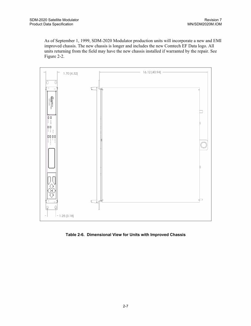
As of September 1, 1999, SDM-2020 Modulator production units will incorporate a new and EMI improved chassis. The new chassis is longer and includes the new Comtech EF Data logo. All units returning from the field may have the new chassis installed if warranted by the repair. See Figure 2-2.
Table 2-6. Dimensional View for Units with Improved Chassis
1.70 [4.32]
1.25 [3.18]
16.12 [40.94]
TRAN
SMIT
STOR
ED
RAN
SMIT
TRANSM
ITTERO
N
SYNC
TESTM
OD
E
POW
ERO
N
SDM
-2020

SDM-2020 Satellite Modulator Revision 7 Product Data Specification MN/SDM2020M.IOM
2-8
This page is intentionally left blank.

3-1
Chapter 3. INSTALLATION
CAUTION
The equipment contains parts and assemblies sensitive to damage by Electrostatic Discharge (ESD). Use ESD precautionary procedures when touching, removing, or inserting PCBs.
3.1 UNPACKING
The modulator and manual are packaged in pre-formed, reusable, cardboard cartons containing foam spacing for maximum shipping protection.
CAUTION
Do not use any cutting tool that will extend more than 1 inch (2.54 cm) into the container. This can cause damage to the modulator.
To remove the modulator:
1 Cut the tape at the top of the carton indicated by OPEN THIS END
2 Remove the cardboard/foam space covering the modulator
3 Remove the modulator, manual, and power cord from the carton
4 Save the packing material for storage or reshipment purposes
5 Inspect the equipment for any possible damage incurred during shipment
6 Check the equipment against the packing list to ensure the shipment is correct
7 Refer to Section 3.2 for installation instructions

SDM-2020 Satellite Modulator Revision 7 Installation MN/SDM2020M.IOM
3-2
3.2 INSTALLATION
A complete modulator consists of the SDM-2020 main unit and an optional plug-in data interface. The modulator is shipped with the data interface installed in the unit. Changing a data interface is easily accomplished in the field and does not require disassembly of the main unit.
Refer to applicable chapters for information on removing and installing data interface modules.
Install the modulator as follows:
1 Optional: Install the mounting bracket in equipment rack (Figure 3-1). Install and tighten the bracket bolts.
2 Loosen the screw with flat washer located on the left-side of modem chassis. Mount the modem chassis into the equipment rack and slide the screw with flat washer through the slot of the mounting bracket. Tighten the screw sufficiently to allow the modem chassis to slide in the bracket.
3 Connect the cables to the proper locations on the rear panel.
4 Observe the modulator. The modulator powers ON automatically when the primary power connection is made (plugged in). Before plugging in the modulator, become familiar with the front panel operation as described in Chapter 5.
Note: If there is any problem with the installation, contact Comtech EF Data’s Customer Support Department: [email protected]

SDM-2020 Satellite Modulator Revision 7 Installation MN/SDM2020M.IOM
3-3
EquipmentRack
MountingRail
#10 Socket headscrew
BRACKETBOLTS
SupportBracket
IDU* Note: Components of mounting kit KT/6228-1
*
*
*
Figure 3-1. Installation of the Optional Mounting Bracket, KT/6228-1

SDM-2020 Satellite Modulator Revision 7 Installation MN/SDM2020M.IOM
3-4
3.2.1 CABLING
IMPORTANT
The following cabling instructions are generic. Comtech EF Data realizes there are several different cabling applications for the SDM- 2020 Modulator, however, this manual cannot illustrate or described the various installation configurations.
Figure 3-2. Rear View of SDM-2020M Rack Installed
Item # Cable From To Comment
1 Prime Power Cord I.E.C Rack Power Source 3-Pong Power Cord 2 Remote J1 EXT PC Terminal 9-pin D 3 Fault J2 EXT PC Terminal 9-pin D 4 Data Interface,
Customer Select Interface
JX SERIAL JX PARALLEL JX AUX
Cissco router or equivalent
Refer to Chapter 6 Data Interfaces
5 IF Output CP1 Upconverter or RF Terminal
BNC
6 Ground #10-32 Stud Rack Equipment
Lengend Prime Power Cord Remote Ribbon Cable Fault Cable Data Interface IF Output Ground
J1 J2
TE TOMRE A
UL
F
J21J21
TROINMMO
RF 11.5A 50-60Hz100-240V~
T2A, 250V
ECL / HSSI INTERFACEJ3
Up Converter
Router
1
23
45
6
Back of Rack

SDM-2020 Satellite Modulator Revision 7 Installation MN/SDM2020M.IOM
3-5
3.2.2 DATA INTERFACES
The data interface is a removable, plug-in module that provides a terrestrial connection to the modulator. An interface consists of a Printed Circuit Board (PCB) attached to a faceplate. The faceplate contains connectors appropriate for the interface type, and two captive mounting screws.
Appendix C describe the various data interfaces. After a different interface type has been installed, the modulator recognizes the change upon power up, and defaults to valid parameters for the new interface.
CAUTION
To avoid damaging the modulator, always disconnect the power before removing or installing a data interface.
Figure 3-3 is an example of a typical data interface.
J3PA
RA
LLEL
J4SE
RIAL
J5AU
X
Figure 3-3. Typical Data Interface Module

SDM-2020 Satellite Modulator Revision 7 Installation MN/SDM2020M.IOM
3-6
3.2.2.1 DATA INTERFACE REMOVAL 1 Disconnect power from the modulator.
2 Use a Phillips screwdriver to loosen the two captive screws on the faceplate of the data interface.
3 Grasp the data interface by the faceplate handle.
4 Carefully pull the data interface out of the slot.
3.2.2.2 DATA INTERFACE INSTALLATION 1 Disconnect power from the modulator.
2 Grasp the data interface by the faceplate handle.
3 Locate the opening at the rear of the modulator.
4 Carefully align the data interface with the card guides inside the modulator and insert the data interface into the opening.
5 Push the data interface firmly into the slot, ensuring a good connection.
6 Align the captive screws located on the faceplate with the holes on the modulator rear panel.
7 Use a Phillips screwdriver to tighten the screws.
4- 1
Chapter 4. EXTERNAL CONNECTIONS
4.1 EXTERNAL CONNECTIONS
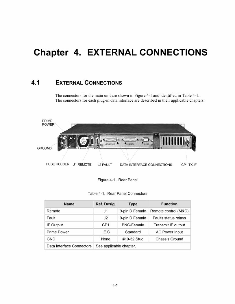
The connectors for the main unit are shown in Figure 4-1 and identified in Table 4-1. The connectors for each plug-in data interface are described in their applicable chapters.
PRIMEPOWER
GROUND
J1 REMOTEFUSE HOLDER J2 FAULT DATA INTERFACE CONNECTIONS CP1 TX-IF
Figure 4-1. Rear Panel
Table 4-1. Rear Panel Connectors
Name Ref. Desig. Type Function
Remote J1 9-pin D Female Remote control (M&C)
Fault J2 9-pin D Female Faults status relays
IF Output CP1 BNC-Female Transmit IF output
Prime Power I.E.C Standard AC Power Input
GND None #10-32 Stud Chassis Ground
Data Interface Connectors See applicable chapter.

SDM-2020 Satellite Modulator Revision 7 External Connections MN/SDM2020M.IOM
4-2
4.1.1 REMOTE CONNECTOR AND PINOUT (J1)
The remote control connection is a 9-pin female D connector located on the rear panel of the modulator. Screw locks are provided for mechanical security of the mating connector.
The remote connector provides a means for issuing commands and determining the unit status. This connector provides EIA-232, EIA-485 (2-wire), and EIA-485 (4-wire) operation. The communications protocol and the control and status commands are described in Appendix A.
Table 4-2. Remote Control Connector Pinout (J1)
Remote Control Connector (J1) Pinout EIA-232C EIA-485 (2) EIA-485 (4)
Signal Type Signal Type Signal Type Pin #s GND GND GND GND GND GND 1 RXD O N/A N/A N/A N/A 2 TXD I N/A N/A N/A N/A 3 N/A N/A +RX/+TX I/O +TX I 4 GND GND -RX/-TX I/O -TX I 5 DSR O N/A N/A N/A N/A 6 RTS I N/A N/A N/A N/A 7 CTS O +RX/+TX I/O +RX O 8 N/A N/A -RX/-TX I/O -RX O 9

SDM-2020 Satellite Modulator Revision 7 External Connections MN/SDM2020M.IOM
4-3
4.1.2 FAULT CONNECTOR (J2)
The fault interface connection is a 9-pin female D connector located on the rear panel of the modulator. Screw locks are provided for mechanical security on the mating connector.
The fault connector provides FORM-C contact closures for fault reporting. The two FORM-C summary fault contacts are Modulator and Common Equipment. To obtain a system summary fault, connect all of the FORM-C contacts in parallel.
Table 4-3. Faults Status Relays Connector Pinout (J2)
Pins Connected Signal
Function Name Pin # TypeFault/ Alarm OK
Power OFF
Common Equipment Fault CE_NO CE_COM CE_NC
1 2 3
FC FC FC
2-3
1-2
2-3
Modulator Fault MOD_NO MOD_COMMOD_NC
4 5 6
FC FC FC
5-6
4-5
5-6
Modulator Alarm ALM_NO ALM _COMALM _NC
7 8 9
FC FC FC
7-8
8-9
8-9
Note: A connection between the common (COM) and normally open (NO) contacts
indicates no fault.
4.1.3 TRANSMIT IF OUTPUT CONNECTOR (CP1)
CP1 is a BNC connector for the TX IF signal output. The output impedance is 75Ω (50Ω optional). The output is a modulated carrier between 50 and 180 MHz.
4.1.4 AC POWER
This unit shall be operated from the type of power source indicated on the marking label. If power source is unknown, contact the local power company. Damage to the unit may be the result.

SDM-2020 Satellite Modulator Revision 7 External Connections MN/SDM2020M.IOM
4-4
Type TN System Only (EN 60950, Paragraph 1.2.12.1) - Power Distribution System: Power distribution system having one point directed toward the earth, the exposed conductive parts of the installation being connected to that point by protective earth conductors. This equipment shall not be used with single-phase three-wire (PE, TT, or IT) type power distribution system.
The A/C power is supplied to the modulator by a standard, detachable, non-locking, 3-prong power cord. The cord connects to a fused IEC 320-type power receptacle.
Internal to the unit, color-coded wiring is used in the A/C mains as follows:
UK Europe USA
(BS 1363) (CEE 7/7) (NEMA 5-15P)
Live Brown Brown Black
Neutral Blue Blue White
Ground Green/Yellow Green/Yellow Green
Note: Since the equipment is not fitted with an ON/OFF switch, the A/C socket-outlet shall be installed near the equipment and shall be easily accessible (EN 60950 1.7.2).
IMPORTANT
Before replacing the fuses in the A/C input connector, disconnect the equipment from the power supply. Failure to do so may expose hazardous voltages. Unplug the equipment from the local power supply socket.
4.1.5 FUSE DATA
Fuse Type: Littlefuse 215002 5 x 20 mm
Fuse: T2A H250V
Time Delay, 2A, High Breaking Capacity
Double Pole
(Approved to IEC 127, Sheet V and Underwriters Laboratories)
Refer to input power requirements as specified in Chapter 2.
Replacing a fuse
1 Remove the fuseholder on the back of the IEC 320 style A/C input connector (Figure 4-1).
2 Replace fuse with same or equivalent rated part and/or model number.

SDM-2020 Satellite Modulator Revision 7 External Connections MN/SDM2020M.IOM
4-5
4.1.6 DC POWER (OPTIONAL)
DC power is an available option. Contact Comtech EFData’s Customer Support for further assistance.
4.1.7 GROUND (GND) OR EARTH
A #10-32 stud is available on the rear panel for the purpose of connecting a common chassis ground among all of the equipment.
Note: A safety ground is provided through the AC power connector.
4.1.8 LITHIUM BATTERY REPLACEMENT
CAUTION
Danger of explosion if battery is incorrectly replaced. Replace only with the same or equivalent type recommended by the manufacturer. Dispose of used batteries according to the manufacturer’s instructions.
4.2 PROPER OPERATIONS FOR EMISSIONS (CE)
To ensure compliance with the EMC Directive 89/336/EEC, properly shielded cables for Data I/O shall be used. These cables shall be doubled-shielded from end-to-end, ensuring a continuous ground shield.

SDM-2020 Satellite Modulator Revision 7 External Connections MN/SDM2020M.IOM
4-6
This page is intentionally left blank.

5-1
Chapter 5. FRONT PANEL OPERATIONS
5.1 FRONT PANEL The modem front panel (Figure 5-1) enables control of modem configuration parameters and displays the modem status.
POWER ONSYNC
TRANSMITTER ONTEST MODE
TRANSMITSTOREDTRANSMIT
ENTER
CLEARALARMS
Modulator
FAULTS
Figure 5-1. Front Panel View
The front panel features include:
• 32-character, 2-line LCD display
• 6-button keypad for local control • 7- LEDs to provide overall status at a glance
All functions are accessible at the front panel by entering one of six pre-defined Function Select categories or levels:
• Configuration
• Monitor
• Faults/Alarms
• Stored Faults/Alarms
• Utility

SDM-2020 Satellite Modulator Revision 7 Front Panel Operation MN/SDM2020M.IOM
5-2
5.2 LED INDICATORS
The seven LEDs on the front panel indicate:
• General modem summary faults
• Status
• Alarms The indicators are defined in Table 5-1 as follows:
Table 5-1. LED Indicators
Name LED Description Faults
Transmit Red A fault condition exists in the transmit chain. Stored Yellow A fault has been logged and stored.
The fault may or may not be active. Status
Power On Green Power is applied to the modem. SYNC Green The modulator is synchronized to the data in the selected framing
mode. The LED is continuously On when the DVB Framing Type is None.
Transmitter On Green Transmitter is currently On. This indicator reflects the actual condition of the transmitter, as opposed to be programmed condition.
Test Mode Yellow Flashes when the modem is in a test configuration. Alarms
Transmit Yellow A transmit function is in an alarm condition.

SDM-2020 Satellite Modulator Revision 7 Front Panel Operation MN/SDM2020M.IOM
5-3
5.3 FRONT PANEL KEYPAD
IMPORTANT
The keypad has an auto-repeat feature. If a key is held down for more than 1 second, the key action will repeat, automatically, at the rate of 15 keystrokes per second. This is particularly useful when editing numeric fields, with many digits, such as frequency or data rate.
The front panel keypad permits local operation of the modem. The keypad consists of six keys (Figure 5-2).
ENTER
CLEAR
Figure 5-2. Keypad
Each key provides one or more logical functions. These functions are defined in the following table.
ENTER This key is used to select a displayed function or to execute a
modem configuration change.
CLEAR This key is used to back out of a selection or to cancel a configuration change which has not been executed using [ENTER]. Pressing [CLEAR] generally returns the display to the previous selection.
Left and Right Diamond Keys
These keys are used to move to the next selection or to move the cursor for certain functions. Note: Throughout this chapter, [←] and [→] are used to indicate left and right diamond keys.
Top and Bottom Diamond Keys
These keys are used primarily to change configuration data (numbers). At times, they are also used to move from one section to another. Note: Throughout this chapter, [↑] and [↓] are used to indicate top and bottom diamond keys.

SDM-2020 Satellite Modulator Revision 7 Front Panel Operation MN/SDM2020M.IOM
5-4
The modem responds by beeping whenever a key is pressed:
• A single beep indicates a valid entry and the appropriate action was taken • A double beep indicates an invalid entry or a parameter is not available for
operation.
5.4 MENU SYSTEM Note: The menus show features and options that are not available. However, they are shown to preserve the menu structure and reserve the structure for the future. This does not imply an intent or obligation to add these features or options in the future.
Use the Main menu in Figure 5-3 as a quick reference for accessing the modem functions. When the modem power is applied, the base level of the menu system displays the sign-on message:
• Line 1 of the sign-on message is the modem model number and type.
• Line 2 is the version number of the firmware.
The main level of the menu system is Function Select. To access this level from the sign-on message, press the [←] or [→] keys. From the Function Select menu; select one of the functional categories:
• Configuration
• Monitor
• Faults/Alarms
• Stored Faults/Alarms
• Utility
Press [←] or [→] to move from one selection to another. When line 2 displays the desired function, select that level by pressing [ENTER]. After entering the appropriate functional level, press [←] or [→] to move to the desired function.

SDM-2020 Satellite Modulator Revision 7 Front Panel Operation MN/SDM2020M.IOM
5-5
To view or change the modem’s configuration, enter the Configuration level from the Function Select menu. Once in the Configuration menu, press [←] or [→] to scroll through the Configuration menu selection:
• Modulator
• Demodulator
• Interface
• Save
• Recall
Press [ENTER] to select the desired Configuration menu option. To view the options for the selected configuration parameters, press [←] or [→]. To change a configuration parameter, press [ENTER] to begin the change process. Press [↑] or [↓] to change the parameters. After the display represents the correct parameters, press [ENTER] to execute the change. This action initiates the necessary programming by the modem.
To undo a parameter change prior to execution, press [CLEAR]. Notes:
1. Figure 5-3 list the front panel menu window selections. 2. Comtech EF Data recommends that selection of the desired Modem Type be
made prior to making any other setting. This procedure is located in the Utility Modem Type menu.
3. Menus or commands that are specific to certain modem configurations are only accessible after selecting the appropriate modem configuration. This prevents incompatible parameters from accidentally being selected.
4. All of the windows are accessible in the Custom mode. Take caution not to select incompatible parameters, as the modem does not shut out incompatible command choices in the Custom mode.
SDM-2020 Satellite Modulator Revision 7 Front Panel Operation MN/SDM2020M.IOM
5-6
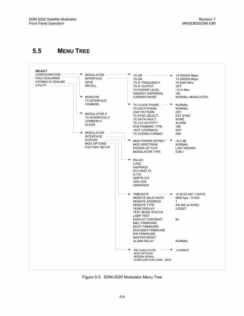
5.5 MENU TREE
SELECTCONFIGURATIONFAULTS/ALARMSSTORED FLTS/ALMSUTILITY
MODULATORINTERFACESAVERECALL
MONITORTX INTERFACECOMMON
MODULATOR XTX INTERFACE XCOMMON XCLEAR
MODULATORINTERFACESYSTEMMOD OPTIONSFACTORY SETUP
TX-DR 15.000000 MbpsTX-SR 15.000000 MbpsTX-IF FREQUENCY 70.0000 MHzTX-IF OUTPUT OFFTX POWER LEVEL -10.0 dBmENERGY DISPERSAL ONCARRIER MODE NORMAL-MODULATED
TX CLOCK PHASE NORMALTX DATA PHASE NORMAL2047 PATTERN OFFTX SYNC SELECT EXT SYNCTX DATA FAULT NONETX CLK ACTIVITY ALARMDVB FRAMING TYPE 188 INTF LOOPBACK OFFTX CODING FORMAT AMI
MOD POWER OFFSET +0.0 dBMOD SPECTRUM NORMALPOWER UP TX-IF LAST KNOWNMODULATOR TYPE DVB-1
RS-422LVDSASI/RS422ECL/HSSI TXG.703SMPTE-310ASI/LVDSUNKNOWN
TIME/DATE 12:00:00 AM / 7/04/76REMOTE BAUD RATE 9600 bps / EVENREMOTE ADDRESS 1REMOTE TYPE RS-485 (4-WIRE)YEAR DISPLAY 2-DIGITTEST MODE STATUSLAMP TESTDISPLAY CONTRAST 64M&C FIRMWAREBOOT FIRMWAREENCODER FIRMWARER/S FIRMWAREMASTER RESETALARM RELAY NORMAL
REV EMULATION CURRENTMOD OPTIONSMODEM SERIALCONFIURATION CODE - MOD
Figure 5-3. SDM-2020 Modulator Menu Tree

SDM-2020 Satellite Modulator Revision 7 Front Panel Operation MN/SDM2020M.IOM
5-7
5.6 OPENING SCREEN
This screen is displayed whenever power is first applied to the unit:
SDM-2020 MOD VER: 9.1.2
Press any key to go to the top level selection screen.
5.6.1 FUNCTION SELECT:CONFIGURATION
FUNCTION SELECT CONFIGURATION
The following choices are present:
Modulator This menu branch permits the user to fully configure the modulator.
Interface This branch permits the user to fully configure the transmit phase of the modulator.
Save The user can save up to 10 different modulator configurations in the non-volatile memory of the unit.
Recall The user can recall the 10 different modulator configurations from the non-volatile memory of the unit.
5.6.1.1 FUNCTION SELECT:CONFIGURATION:MODULATOR
CONFIGURATION MODULATOR
Use this menu to configure the unit in a step-by-step process using each successive menu.
Use the [↑ ] [↓ ] arrows to make the desired selection, then press <ENTER>.

SDM-2020 Satellite Modulator Revision 7 Front Panel Operation MN/SDM2020M.IOM
5-8
5.6.1.1.1 CONFIGURATION:MODULATOR:TX-DR
TX-DR QPSK 1/2 15.000000 Mbps
Selections include: QPSK 1/2, 3/4, 5/6, or 7/8
8PSK 2/3, 5/6, or 7/8
16QAM 3/4 or 7/8
Programming is done by either data rate or symbol rate. Data rate refers to the equivalent serial data rate at the data interface connector. Symbol rate refers to the modulation rate after framing, trellis (Viterbi) coding, and Reed-Solomon coding are applied.
The framing type selection affects the symbol rate (if programming from the data rate [TX-DR] menu), or the data rate (if programming from the symbol rate [TX-SR] menu). If data rate is programmed, the symbol rate menu is updated to reflect the code rate and framing selections. If symbol rate is programmed, the data rate display is similarly updated.
Programing the modulator data rate (DR) from 1.5 to 100 Mbit/s, in 1 bit/s steps is limited by code rate and data interface.
1 Press <ENTER> while the menu is displayed to turn OFF TX-IF Output.
2 Press <ENTER> a second time while the menu is displayed to turn ON TX-IF OUTPUT.
3 Observe the on/off status of the TRANSMITTER LED.
On entry, the current data rate is displayed with the flashing cursor on the first character.
1 Press [←] or [→] to move the flashing cursor.
2 Press [↑] or [↓] to increase or decrease the digit at the flashing cursor.
3 Press <ENTER> to execute the change.
When <ENTER> is pressed to change the data rate, the transmitter is automatically turned OFF to prevent the possible swamping of other channels.
Another menu is displayed that allows the operator to turn the transmitter ON again, simply by pressing <ENTER>.

SDM-2020 Satellite Modulator Revision 7 Front Panel Operation MN/SDM2020M.IOM
5-9
5.6.1.2 CONFIGURATION:MODULATOR:TX-SR
TX-SR QPSK 7/8 15.000000 Msps
Selections include: QPSK 1/2, 3/4, 5/6, or 7/8
8PSK 2/3, 5/6 or 7/8
16QAM 3/4 or 7/8
Use this menu to program the modulator symbol rate (SR) from 1 to 37.5, in 1 sym/s steps, limited by code rate and data interface.
Programming is done by either data rate or symbol rate. Data rate refers to the equivalent serial data rate at the data interface connector.
Symbol rate refers to the modulation rate after framing, trellis (Viterbi) coding, and Reed-Solomon coding are applied.
The framing type selection affects the symbol rate (if programming from the data rate [TX-DR] menu), or the data rate (if programming from the symbol rate [TX-SR] menu). If data rate is programmed, the symbol rate menu is updated to reflect the code rate and framing selections. If symbol rate is programmed, the data rate display is similarly updated.
1 Press <ENTER> while the menu is displayed to turn OFF TX-IF Output.
2 Press <ENTER> a second time while the menu is displayed to turn ON TX-IF OUTPUT.
3 Observe the on/off status of the TRANSMITTER LED.
On entry, the current symbol rate is displayed with the flashing cursor on the first character.
1 Press [←] or [→] to move the flashing cursor.
2 Press [↑] or [↓] to increase or decrease the digit at the flashing cursor.
3 Press [ENTER] to execute the change.

SDM-2020 Satellite Modulator Revision 7 Front Panel Operation MN/SDM2020M.IOM
5-10
5.6.1.3 CONFIGURATION:MODULATOR:TX-IF FREQUENCY
TX-IF FREQUENCY 70.0000 MHz
Use this menu to program the modulator transmit frequency.
Range available: 50 to 180 MHz, in 2.5 kHz steps.
1 Press [ENTER] while this menu is displayed to turn OFF TX-IF Output.
2 Press [ENTER] a second time while this menu is displayed to turn ON TX-IF OUTPUT.
3 Observe the on/off status of the TRANSMITTER LED.
On entry, the current transmitter frequency is displayed with the flashing cursor on the first character.
1 Press [←] or [→] to move the flashing cursor.
2 Press [↑] or [↓] to increase or decrease the digit at the flashing cursor.
3 Press [ENTER] to execute the change.
5.6.1.4 CONFIGURATION:MODULATOR:TX-IF OUTPUT
TX-IF OUTPUT OFF
Use this menu to program the modulator output to ON, OFF, or MORE.
On entry, the current status of the output is displayed.
1 Press [↑] or [↓] to select ON or OFF.
2 Press [ENTER] to execute the change. Additionally:
1 Press [ENTER] when MORE is displayed to show the menu for toggling TX-IF ON and OFF. In this mode, the carrier is turned ON [↑] or OFF [↓] without having to press [ENTER].
2 Press [ENTER a second time with this menu displayed to turn ON TX-IF OUTPUT.
3 Observe the on/off status of the TRANSMITTER LED.

SDM-2020 Satellite Modulator Revision 7 Front Panel Operation MN/SDM2020M.IOM
5-11
5.6.1.5 CONFIGURATION:MODULATOR:TX-IF POWER LEVEL
TX POWER LEVEL -10.0 dBm
Use this menu to program the modulator output power level.
Range available: +5 to -20 dBm, in 0.1 dBm steps.
On entry, the current transmitter power level is displayed with the flashing cursor on the first character.
1 Press [↑] or [↓] to increase or decrease the output power level in 0.1 dB steps.
2 Press <ENTER> to execute the change.
5.6.1.6 CONFIGURATION:MODULATOR:ENERGY DISPERSAL
ENERGY DISPERSAL (SCRAMBLER) ON
Use this menu to program the energy dispersal ON or OFF.
On entry, the current status of the DVB Energy Dispersal is displayed.
1 Press [↑] or [↓] to select ON or OFF.
2 Press <ENTER> to execute the change.

SDM-2020 Satellite Modulator Revision 7 Front Panel Operation MN/SDM2020M.IOM
5-12
5.6.1.7 CONFIGURATION:MODULATOR:CARRIER MODE
CARRIER MODE NORMAL-MODULATED
Use this menu to program the modulator for continuous wave mode. Four modes of operation are available:
NORMAL-MODULATED
Normal modulated data. The Carrier Mode is in the OFF position for data modulation.
DUAL-CW Mode A test mode that generates a dual side-band suppressed carrier signal. Side-bands are one-half the symbol rate from the carrier. This is used to check the channel balance and carrier null.
OFFSET-CW Mode
A test mode that generates a single upper side-band suppressed carrier signal. The upper side-band is one-quarter the symbol rate from the carrier. This is used to check the quadrature.
CENTER-CW Mode
A test mode that generates a carrier at the current modulator frequency. This can be used to measure the output frequency.
1 Press <ENTER> while in the NORMAL-MODULATED mode to turn OFF the TX-IF Output.
2 Press <ENTER> a second time to turn ON the TX-IF OUTPUT.

SDM-2020 Satellite Modulator Revision 7 Front Panel Operation MN/SDM2020M.IOM
5-13
5.6.2 FUNCTION SELECT:CONFIGURATION:INTERFACE
CONFIGURATION INTERFACE
Use this menu to configure the unit in a step-by-step process by using each successive menu.
Use the [↑ ] [↓ ] arrows to make the sesired selection, then press <ENTER>.
5.6.2.1 CONFIGURATION:INTERFACE:TX CLOCK PHASE
TX CLOCK PHASE NORMAL
Note: Not shown with G.703 data interface installed. Use this menu to program the TX Clock Phase to NORMAL or INVERT.
On entry, the current setting for the TX Clock Phase is displayed.
1 Press [↑] or [↓] to select NORMAL or INVERT.
2 Press [ENTER] to execute the change.
5.6.2.2 CONFIGURATION:INTERFACE:TX DATA PHASE
TX DATA PHASE NORMAL
Use this menu to program the TX Data Phase to NORMAL or INVERT.
On entry, the current setting for the TX Data Phase is displayed.
1 Press [↑] or [↓] to select NORMAL or INVERT.
2 Press [ENTER] to execute the change.

SDM-2020 Satellite Modulator Revision 7 Front Panel Operation MN/SDM2020M.IOM
5-14
5.6.2.3 CONFIGURATION:INTERFACE:2047 PATTERN
2047 PATTERN OFF
Use this menu to program the transmitter to ON or OFF to insert a 2047 pattern instead of the normal transmit data.
Upon entry, the current status is displayed.
1 Press [↑] or [↓] to make the selection.
2 Press [ENTER] to execute the change.
5.6.2.4 CONFIGURATION:INTERFACE:TX SYNC SELECT
TX SYNC SELECT EXT SYNC
Note: ASI/LVDS (ASI Mode) only can use CORR ON DAT.
Use this menu to program the transmitter for any one of the following methods of synchronization:
EXT SYNC Available only on interfaces with an external SYNC signal.
CORR ON DAT
The external sync line is ignored. Data spec is detected by correlating the data stream for the MPEG-2 sync pattern.
AUTO DETECT
Automatically selects the most reliable sync indicator. The external sync line is utilized, if available. Otherwise, the correlate on data method is used for sync. (Available only on interfaces with an external SYNC signal.)
Upon entry, the current TX Sync Select is displayed.
1 Press [↑] or [↓] to make the selection.
2 Press [ENTER] to execute the change.

SDM-2020 Satellite Modulator Revision 7 Front Panel Operation MN/SDM2020M.IOM
5-15
5.6.2.5 CONFIGURATION:INTERFACE:TX DATA FAULT
TX DATA FAULT NONE
Upon entry, the current TX Data Fault that is being monitored is displayed.
1 Press a directional key to select one of the following modes:
NONE The TX interface alarm DATA/ASI is not activated.
Alarm Indication Signal (ASI)
Sets TX interface alarm DATA/ASI to monitor an alarm condition of all 1s from customer data input to the modulator.
DATA STABLE Sets TX interface fault DATA/ASI to monitor an alarm condition of all 1s or 0s. This is referred to as a data-stable condition, which means that the data is not transitioning.
2 Press [↑] or [↓] to make the selection.
3 Press [ENTER] to execute the change.
Note: Detection of these conditions produces an alarm indication, not a fault.
5.6.2.6 CONFIGURATION:INTERFACE:TX CLK ACTIVITY
TX CLK ACTIVITY ALARM
This parameter sets the response of the modulator when either a loss of clock activity or a clock out-of-tolerance condition is detected. The response generates either an alarm or fault based on the following selections:
• Alarm (TX-IF Remains ON)
• Fault (Shuts TX-IF OFF)
Upon entry, the new response is indicated.
Press <ENTER> to execute the change. The alarm condition is indicated for the Alarm selection.
Note: When Fault is selected, an indication is produced that causes the redundancy switch-over.

SDM-2020 Satellite Modulator Revision 7 Front Panel Operation MN/SDM2020M.IOM
5-16
5.6.2.7 CONFIGURATION:INTERFACE:DVB FRAMING TYPE
DVB FRAMING TYPE 188
Note: Pressing <ENTER> in this menu turns off TX-IF Output.
Use this menu to program the DVB framing type for 188, 204, or NONE. The framing type describes the format of the data into the modulator. The equivalent serial data rate at the data interface connector is based upon the clock rate of the incoming data stream.
Upon entry, the current status of the DVB framing type is displayed.
1 Press [↑] or [↓] to make the selection.
2 Press <ENTER> to execute the change.
When <ENTER> is pressed to change the framing type, the transmitter is automatically turned off to prevent the possible swamping of other channels. Another menu is displayed that allows the operator to turn the transmitter on again by pressing <ENTER>.
5.6.2.8 CONFIGURATION:INTERFACE:INTF LOOPBACK
INTF LOOPBACK OFF
Note: Available with either ASI/RS422, G.703, or ASI/LVDS interface installed.
Test mode loops the input data back to the output of the terrestrial interface. Data continues into the modulator. The yellow TEST MODE LED is illuminated when Loopback is turned ON. (See Interface Loop Thru as specified under Utility Interface for additional description.)
Upon entry, the current status of the Interface Loopback is displayed.
1 Press [↑] or [↓] to make the selection.
2 Press <ENTER> to execute the change.

SDM-2020 Satellite Modulator Revision 7 Front Panel Operation MN/SDM2020M.IOM
5-17
5.6.2.9 CONFIGURATION:INTERFACE:TX CODING FORMAT
TX CODING FORMAT AMI
Note: Available with G.703 interface installed.
Use this menu to program the TX coding format for one of these choices:
• AMI
• B8ZS
• HDB3
• B3ZS
On entry, the current status is TX Coding Format displayed.
1 Press [↑] or [↓] to select ON or OFF.
2 Press <ENTER> to execute the change.
5.6.3 CONFIGURATION:SAVE
CONFIGURATION #X SAVE
Use the Configuration Save menu to program configuration parameters into memory on the M&C. There are 10 memory locations that may be used to store specific frequently used configuration setups.
1 Change the configuration parameters to the desired settings.
2 Enter the Configuration Save menu.
3 Press [↑] or [↓] to select a memory location (range = 1 through 10).
4 Press <ENTER> to execute the save.
5.6.4 CONFIGURATION:RECALL
CONFIGURATION #X RECALL
Use the Configuration Recall menu to recall a previously saved configuration setup.
1 Press [↑] or [↓] to select a memory location (range = 1 through 10).
2 Press <ENTER> to execute the recall.

SDM-2020 Satellite Modulator Revision 7 Front Panel Operation MN/SDM2020M.IOM
5-18
5.6.5 FUNCTION SELECT:FAULTS/ALARMS
Selections available: MODULATOR
TX INTERFACE
COMMON
1 Use the [←] [→] arrows to select an alarm type.
2 Press <ENTER>.

SDM-2020 Satellite Modulator Revision 7 Front Panel Operation MN/SDM2020M.IOM
5-19
5.6.5.1 FAULTS/ALARMS:MODULATOR
MODULATOR ------- -
Selections available include the following:
Fault/Alarm Possible Problem and Action IF SYNTHESIZER Modulator IF synthesizer is faulted. This is considered a major alarm and
will turn OFF the modulator output. Return the modulator for repair. DATA CLOCK SYN This alarm is considered a major alarm and will turn OFF the modulator IF output
TX data clock synthesizer fault. This fault is an indication that the internal clock VCO has not locked to the incoming data clock, or the internal clock synthesizer has not locked to the internal reference. Check to see that the proper data rate has been set up and selected. Verify that the incoming data rate matches what has been selected in the modulator. Verify the frequency of the input data clock to be within the lock range of 100 PPM. If the inputs to the modulator are all correct and the problem still exists, replace the modulator and return it for repair.
I CHANNEL This alarm is considered a major alarm and will turn OFF the modulator IF output.
Activity alarm for the I channel digital filter.An alarm in this position indicates either a fault in the scrambler, or if the scrambler is disabled, it indicates a loss of incoming data. If the fault is active with the scrambler turned OFF, check to see that there is input data at the DATA I/O connector. If data is present, the problem could be in the interface section. If the fault is active with the scrambler turned ON, the problem could be in the modulator section. Return the modulator for repair.
Q CHANNEL Activity alarm for the Q channel digital filter. Follow the same procedure as for the I channel.
AGC LEVEL Output power automatic gain control level fault. Indicates that the level at the modulator output is not the level that is programmed. Replace the modulator and return it for repair.
MODULE Modulator module fault. Typically indicates the modulator will not program.This could indicate a problem in the interface between the modulator and M&C due to modulator firmware being installed incorrectly, or a pin not making contact. Verify the modulator firmware is correctly installed. If the problem still exists, return the modulator for repair.
IF MODULE IF module fault. Typically indicates the IF module is not responding. CONFIGURATION Modulator configuration fault. Indicates the modulator cannot execute a
programmed configuration parameter.
1 Use the [←] [→] arrows to make a selection.
2 Press <ENTER>.

SDM-2020 Satellite Modulator Revision 7 Front Panel Operation MN/SDM2020M.IOM
5-20
5.6.5.2 FAULTS/ALARMS:TX INTERFACE
TX INTERFACE ------- -
Selections available include the following:
Fault/Alarm Possible Problem and Action FRAME SYNC Indicates that the modulator cannot synchronize to the data in the selected
framing mode. DATA STABLE/ASI Note: ASI is an alarm, not a switching fault.
Data or ASI. When data fault is selected in the Interface Configuration menu, the fault indicates a data stable condition. This indicates the data is all 1s or 0s (i.e., data is not transitioning). When ASI is selected, the alarm indicates the data is all 1s from customer data input to the modem. When None is selected in the Configuration Interface menu, the TX Data/ASI Fault/Alarm is not activated.
CLOCK PLL Transmitter phase-locked loop fault. Indicates the transmitter Phase-Locked Loop (PLL) is not locked.
CLOCK ACTIVITY Activity detector alarm of the selected interface TX clock. The interface will fall back to the internal clock when this alarm is active. Note: Refer to the Configuration Interface menu, TX CLK ACTIVITY. This menu permits selection of a fault or an alarm indication for clock activity.
FIFO This fault indicates a data under-run/over-run condition. INTERFACE MODULE Interface module fault. Indicates a problem in programming the interface. This
could indicate a problem in the M&C, or in the interface between the interface section and M&C. Return the modulator for repair.
DATA FORMAT This fault indicates a fault with the formatted data. VIDEO FRAME SYNC Video Frame SYNC fault. This fault indicates a loss of synchronization to
incoming video data.
1 Use the [←] [→] arrows to make a selection.
2 Press <ENTER>.

SDM-2020 Satellite Modulator Revision 7 Front Panel Operation MN/SDM2020M.IOM
5-21
5.6.5.3 FAULTS/ALARMS:COMMON
COMMON ------- -
Selections available include the following:
Fault/Alarm Possible Problem and Action BATTERY/CLOCK M&C battery voltage or clock fault. Indicates a low voltage in the memory battery.
Typically will be active when a modulator has been Hard Reset, or the firmware has been changed. When a Hard Reset has been executed or the firmware has been changed, this fault will typically be active when the modulator is first turned on. It should automatically clear as the battery charges up.
-12 VOLT SUPPLY
-12V power supply fault. Indicates a high or low voltage condition. Level is ± 5%. Check for a short on the -12V line from the power supply or on the board. Check TP2 on the M&C section to verify the proper -12V monitor voltage (1.06V). If this voltage is not correct, it will verify that the -12V supply is not at the proper level. This would indicate the power supply is faulted. Return modulator for repair.
+12 VOLT SUPPLY
+12V power supply fault. Use the same procedure as with -12V fault. To verify the +12V power supply voltage, check TP4 on the M&C. A voltage of 3.81V will be monitored when the +12V is at the proper level.
+5 VOLT SUPPLY +5V power supply fault. Use the same procedure as with -12V fault. To verify the +5V power supply voltage, check TP5 on the M&C section. A voltage of 2.5V will be monitored when the +5V is at the proper level.
CONTROLLER Controller fault. Indicates loss of power in the M&C card. Typically indicates the controller has gone through a power on-off cycle.
1 Use the [←] [→] arrows to make a selection.
2 Press <ENTER>.

SDM-2020 Satellite Modulator Revision 7 Front Panel Operation MN/SDM2020M.IOM
5-22
5.6.6 FUNCTION SELECT:STORED FLTS/ALMS Select MODULATOR, TX INTERFACE, or COMMON using the [←] [→] arrows, then press <ENTER>. The modulator stores the first 10 (Flt0 through Flt9) occurrences of fault status changes in each of the three major fault categories. Each fault status change is stored with the time and date of the occurrence. Stored faults may be viewed by entering the Stored Faults level from the Function Select menu. All stored faults may be cleared by executing the CLEAR Stored Faults? Command from the Stored Faults level. Stored faults are not maintained through a controller power-on reset cycle. However, the last known time is maintained in non-volatile RAM, and upon power-down, a common equipment fault is logged (Flt0) with that time and date. On power-up, an additional common equipment fault is also logged (Flt1) to indicate the power-up time and date. On power-up, the power-down and power-up times are logged as common equipment fault 0 and common equipment fault 1. Upon entering the Stored Faults level, press [←] or [→] to move between the fault groups and the CLEAR Stored Faults?? Selections. The time and date of the first stored fault status (Flt0) for the selected group will be displayed alternately on line 2 of the display. Press [↑] or [↓] to cycle through the selected group’s stored fault status (Flt0 through Flt9). To display the fault status associated with the displayed time and date, press [ENTER]. At this time, press [←] or [→] to move the flashing cursor to the fault to be identified. Note: Faults are stored in time sequence, with the oldest fault status change stored in
Flt0, and the most recent in Flt9. Only the first 10 fault status changes are stored, additional faults are ignored until the log is cleared. All stored faults, which have not been used, indicate No Fault on the display.

SDM-2020 Satellite Modulator Revision 7 Front Panel Operation MN/SDM2020M.IOM
5-23
5.6.6.1 STORED FLTS/ALMS:MODULATOR
MODULATOR X STORED TIME/DATE
Selections available include the following:
IF SYNTHESIZER AGC LEVEL
DATA CLOCK SYN MODULE
I CHANNEL IF MODULE
Q CHANNEL CONFIGURATION
1 Use the [←] [→] arrows to make a selection.
2 Press <ENTER>.
5.6.6.2 STORED FLTS/ALMS:TX INTERFACE
TX INTERFACE X STORED TIME/DATE
Selections available include the following:
FRAME SYNC FIFO
DATA STABLE/AIS INTERFACE MODULE
CLOCK PLL DATA FORMAT
CLOCK ACTIVITY VIDEO FRAME SYNC
1 Use the [←] [→] arrows to make a selection.
2 Press <ENTER>.

SDM-2020 Satellite Modulator Revision 7 Front Panel Operation MN/SDM2020M.IOM
5-24
5.6.6.3 STORED FLTS/ALMS:COMMON
COMMON X STORED TIME/DATE
Selections available include the following:
BATTERY/CLOCK
+12 VOLT SUPPLY
–12 VOLT SUPPLY
+5 VOLT SUPPLY,CONTROLLER
CONTROLLER
1 Use the [←] [→] arrows to make a selection.
2 Press <ENTER>.
5.6.6.4 STORED FLTS/ALMS:CLEAR ??
CLEAR ?? STORED TIME/DATE
1 To clear the stored faults currently logged, press <ENTER>
2 Once the CLEAR Stored Faults/YES?? selection is displayed, press <ENTER> again to clear.

SDM-2020 Satellite Modulator Revision 7 Front Panel Operation MN/SDM2020M.IOM
5-25
5.6.7 FUNCTION SELECT:UTILITY
CAUTION
The Utility Factory Setup menu is for Comtech EF Data service personnel only. Unauthorized access may cause the modulator to operate incorrectly. Changes in the Utility menu may cause changes in other front panel menus.
The Function Select Utility menu is divided into the following categories:
• Modulator
• Interface
• System
• Options
• Factory Setup - (Factory Use Only)
1 Press [←] or [→] to select the desired Utility menu.
2 Press [ENTER].
3 Press [←] or [→] to select the desired function.
5.6.7.1 UTILITY:MODULATOR:MOD POWER OFFSET
MOD POWER OFFSET + 0.0 dB
Use this menu to “offset” the modulator output power readout in the Configuration menu. This feature does not actually change the modulator power level. The function is to change the actual reading to display an offset value in the monitor.
The modulator Power Offset can be set from –40.0 to +40.0 dB, in 0.1 dB increments.
Any value except 0.0 dB causes (ADJ) to be displayed in the TX Power Level screen.
5.6.7.2 UTILITY:MODULATOR:MOD SPECTRUM
MOD SPECTRUM NORMAL
Use this menu to select NORMAL or INVERT for spectrum reversal of the I and Q baseband channels (programmable vector rotation).

SDM-2020 Satellite Modulator Revision 7 Front Panel Operation MN/SDM2020M.IOM
5-26
5.6.7.3 UTILITY:MODULATOR:POWER UP TX-IF
POWER UP TX-IF LAST KNOWN
Use this menu to select the state of the TX-IF Output at power up. Selections include OFF and LAST KNOWN (last known state). Upon entry, the current status of the TX-IF Output power up state is displayed.
1 Press [↑] or [↓] to make the selection.
2 Press <ENTER> to execute the change.
5.6.7.4 UTILITY:MODULATOR:MODULATOR TYPE
MODULATOR TYPE DVB-1
Use this menu to select a spectral mask type of DVB-1 or DVB-2:
DVB-1 This is the default mask and is the “best fit” to the ETS 300 421 mask.
DVB-2 This mask has a sharper cutoff in the transition region from 3 to 40 dB resulting in a narrower spectrum, than DVB-1, at the 35 dB down region.
1 While in this menu, press <ENTER> to turn OFF the TX-IF Output.
2 Press [ENTER] a second time to turn ON the TX-IF OUTPUT.

SDM-2020 Satellite Modulator Revision 7 Front Panel Operation MN/SDM2020M.IOM
5-27
5.6.8 FUNCTION SELECT:UTILITY:INTERFACE
INTERFACE TYPE XXXXXXXXXXX
Selections include:
RS-422 LVDS
ASI/RS422 ECL/HSSI TX
G.703 SMPTE 310
ASI/LVDS UNKNOWN
1 Use the [←] [→] arrows to make a selection.
2 Press <ENTER>.
Additional data interfaces will be added to the menu as they are introduced. If an interface is not recognized, then UNKNOWN is displayed. In this case, a later version of firmware may be required to operate with the data interface.
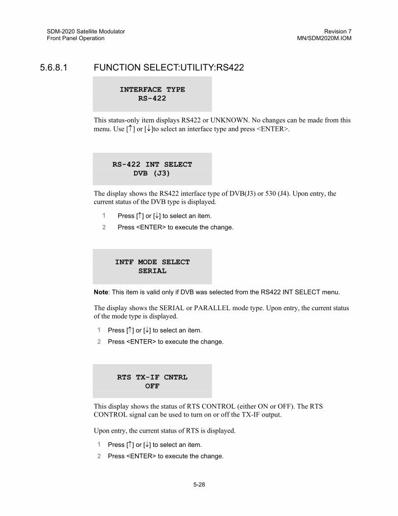
SDM-2020 Satellite Modulator Revision 7 Front Panel Operation MN/SDM2020M.IOM
5-28
5.6.8.1 FUNCTION SELECT:UTILITY:RS422
INTERFACE TYPE RS-422
This status-only item displays RS422 or UNKNOWN. No changes can be made from this menu. Use [↑] or [↓]to select an interface type and press <ENTER>.
RS-422 INT SELECT DVB (J3)
The display shows the RS422 interface type of DVB(J3) or 530 (J4). Upon entry, the current status of the DVB type is displayed.
1 Press [↑] or [↓] to select an item.
2 Press <ENTER> to execute the change.
INTF MODE SELECT
SERIAL
Note: This item is valid only if DVB was selected from the RS422 INT SELECT menu.
The display shows the SERIAL or PARALLEL mode type. Upon entry, the current status of the mode type is displayed.
1 Press [↑] or [↓] to select an item.
2 Press <ENTER> to execute the change.
RTS TX-IF CNTRL OFF
This display shows the status of RTS CONTROL (either ON or OFF). The RTS CONTROL signal can be used to turn on or off the TX-IF output.
Upon entry, the current status of RTS is displayed.
1 Press [↑] or [↓] to select an item.
2 Press <ENTER> to execute the change.

SDM-2020 Satellite Modulator Revision 7 Front Panel Operation MN/SDM2020M.IOM
5-29
RTS STATE NORMAL
This display shows the status of RTS STATE (either NORMAL or INVERT ).
Upon entry, the current status of RTS is displayed.
1 Press [↑] or [↓] to select an item.
2 Press <ENTER> to execute the change.
CTS STATE NORMAL
This display shows the status of CTS STATE (either NORMAL or INVERT).
Upon entry, the current status of CTS is displayed.
1 Press [↑] or [↓] to select an item.
2 Press <ENTER> to execute the change.
DM STATE NORMAL
This display shows the status of DM STATE (either NORMAL or INVERT).
Upon entry, the current status of DM STATE is displayed.
1 Press [↑] or [↓] to select an item.
2 Press <ENTER> to execute the change.

SDM-2020 Satellite Modulator Revision 7 Front Panel Operation MN/SDM2020M.IOM
5-30
5.6.8.2 FUNCTION SELECT:UTILITY:LVDS
INTERFACE TYPE LVDS
This status-only item displays LVDS or UNKNOWN. No changes can be made from this menu. Use [↑] or [↓]to select an interface type and press <ENTER>.
INTF MODE SELECT
SERIAL
This display shows the mode type SERIAL or PARALLEL. Upon entry, the current status of the mode type is displayed.
1 Press [↑] or [↓] to select an item.
2 Press <ENTER> to execute the change.
5.6.8.3 FUNCTION SELECT:UTILITY:ASI/RS422
INTERFACE TYPE ASI/RS422
This status-only item displays ASI/RS422 or UNKNOWN. No changes can be made from this menu. Use [↑] or [↓]to select an interface type and press <ENTER>.
INTERFACE SELECT
ASI
Displays the mode type ASI or RS422. Upon entry, the current status of the mode type is displayed.
1 Press [↑] or [↓] to select an item.
2 Press <ENTER> to execute the change.

SDM-2020 Satellite Modulator Revision 7 Front Panel Operation MN/SDM2020M.IOM
5-31
TX INTF FIRMWARE
FW/6220A
Press <ENTER]> to show the FW Release date.
TX INTF FIRMWARE
11/25/97
Press <CLEAR> to exit the data menu.
ASI LINK SELECT B-LINK (J3)
This display shows the A-LINK (J4) or B-LINK (J3). Upon entry, the current status of the mode type is displayed.
1 Press [↑] or [↓] to select an item.
2 Press <ENTER> to execute the change.
ASI LOOP BW
WIDE
Note: This is for ASI mode only.
This display shows the ASI Loop BW selection of either Wide or Narrow. Upon entry, the current status of the mode type is displayed.
1 Press [↑] or [↓] to select an item.
2 Press <ENTER> to execute the change.

SDM-2020 Satellite Modulator Revision 7 Front Panel Operation MN/SDM2020M.IOM
5-32
INTRFC LOOP THRU OFF
This display shows the Interface Loop thru selection of either ON or OFF. Upon entry, the current status of the mode type is displayed.
1 Press [↑] or [↓] to select an item.
2 Press <ENTER> to execute the change.
When ON is selected, input data is looped to the output of the terrestrial interface and data continues into the modulator. This mode is indential to Interface Loopback specified under the Configuration Interface menu; however, the yellow TEST MODE LED is not illuminated. Conceptually, the data output is operating as a monitor point.
RTS TX-IF CNTRL
OFF
This display shows the status of RTS CONTROL either ON or OFF type. The RTS CONTROL signal can be used to turn on or off the TX-IF output. Upon entry, the current status of the mode type is displayed.
1 Press [↑] or [↓] to select an item.
2 Press <ENTER> to execute the change.
RTS STATE NORMAL
This display shows the RTS selection of either NORMAL or INVERT. Upon entry, the current status of the mode type is displayed.
1 Press [↑] or [↓] to select an item.
2 Press <ENTER> to execute the change.

SDM-2020 Satellite Modulator Revision 7 Front Panel Operation MN/SDM2020M.IOM
5-33
CTS STATE NORMAL
This display shows the CTS selection of either NORMAL or INVERT. Upon entry, the current status of the mode type is displayed.
1 Press [↑] or [↓] to select an item.
2 Press <ENTER> to execute the change.
DM STATE NORMAL
Note: RS-422 Interface Select only.
This display shows the DM selection of either NORMAL or INVERT. Upon entry, the current status of the mode type is displayed.
1 Press [↑] or [↓] to select an item.
2 Press <ENTER> to execute the change.
ST STATE NORMAL
Note: RS-422 Interface Select only.
This display shows the ST selection of either NORMAL or INVERT. Upon entry, the current status of the mode type is displayed.
1 Press [↑] or [↓] to select an item.
2 Press <ENTER> to execute the change.
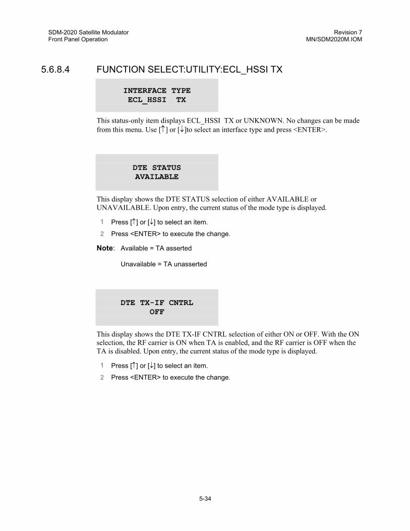
SDM-2020 Satellite Modulator Revision 7 Front Panel Operation MN/SDM2020M.IOM
5-34
5.6.8.4 FUNCTION SELECT:UTILITY:ECL_HSSI TX
INTERFACE TYPE ECL_HSSI TX
This status-only item displays ECL_HSSI TX or UNKNOWN. No changes can be made from this menu. Use [↑] or [↓]to select an interface type and press <ENTER>.
DTE STATUS AVAILABLE
This display shows the DTE STATUS selection of either AVAILABLE or UNAVAILABLE. Upon entry, the current status of the mode type is displayed.
1 Press [↑] or [↓] to select an item.
2 Press <ENTER> to execute the change.
Note: Available = TA asserted
Unavailable = TA unasserted
DTE TX-IF CNTRL OFF
This display shows the DTE TX-IF CNTRL selection of either ON or OFF. With the ON selection, the RF carrier is ON when TA is enabled, and the RF carrier is OFF when the TA is disabled. Upon entry, the current status of the mode type is displayed.
1 Press [↑] or [↓] to select an item.
2 Press <ENTER> to execute the change.
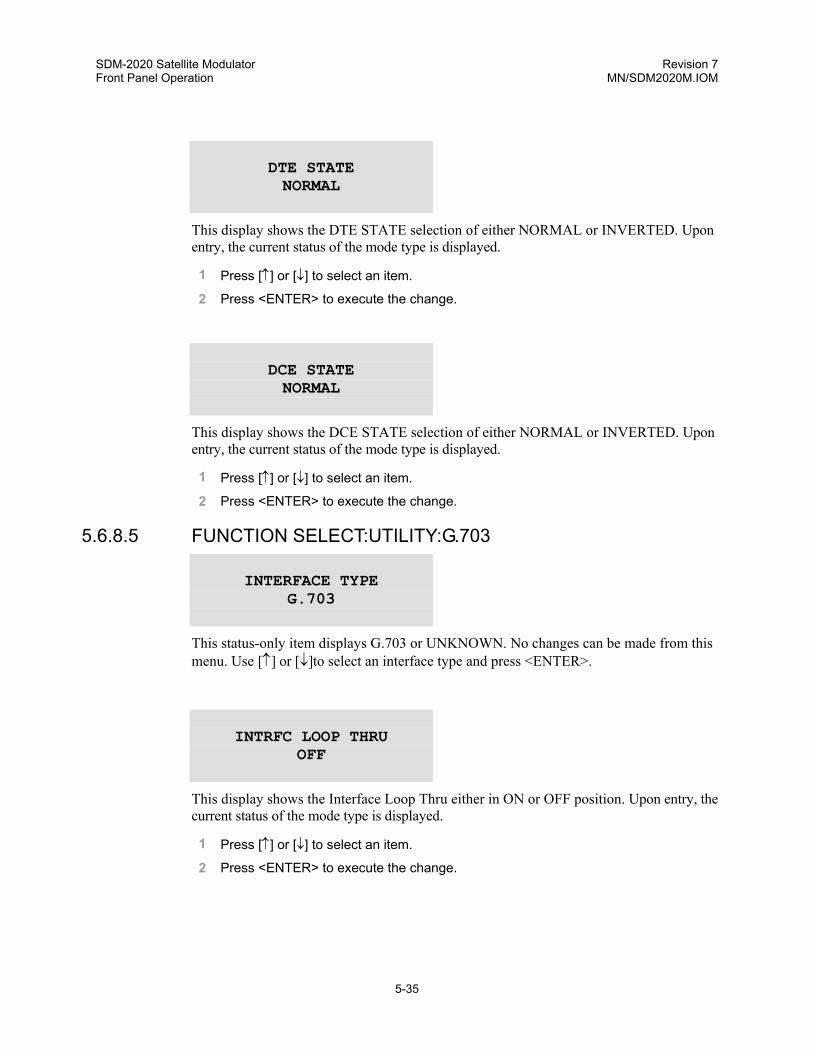
SDM-2020 Satellite Modulator Revision 7 Front Panel Operation MN/SDM2020M.IOM
5-35
DTE STATE NORMAL
This display shows the DTE STATE selection of either NORMAL or INVERTED. Upon entry, the current status of the mode type is displayed.
1 Press [↑] or [↓] to select an item.
2 Press <ENTER> to execute the change.
DCE STATE NORMAL
This display shows the DCE STATE selection of either NORMAL or INVERTED. Upon entry, the current status of the mode type is displayed.
1 Press [↑] or [↓] to select an item.
2 Press <ENTER> to execute the change.
5.6.8.5 FUNCTION SELECT:UTILITY:G.703
INTERFACE TYPE G.703
This status-only item displays G.703 or UNKNOWN. No changes can be made from this menu. Use [↑] or [↓]to select an interface type and press <ENTER>.
INTRFC LOOP THRU
OFF
This display shows the Interface Loop Thru either in ON or OFF position. Upon entry, the current status of the mode type is displayed.
1 Press [↑] or [↓] to select an item.
2 Press <ENTER> to execute the change.

SDM-2020 Satellite Modulator Revision 7 Front Panel Operation MN/SDM2020M.IOM
5-36
When ON is selected, input data is looped to the output of the terrestrial interface and data continues into the modulator. This mode is indential to Interface Loopback specified under the Configuration Interface menu; however, the yellow TEST MODE LED on the front panel is not illuminated. Conceptually, the data output is operating as a monitor point.
RTS TX-IF CNTRL OFF
This display shows the RTS TX-IF Control is either ON or OFF. Upon entry, the current status of the mode type is displayed.
1 Press [↑] or [↓] to select an item.
2 Press <ENTER> to execute the change.
RTS STATE NORMAL
This display shows the RTS State is either NORMAL or INVERT. Upon entry, the current status of the mode type is displayed.
1 Press [↑] or [↓] to select an item.
2 Press <ENTER> to execute the change.
TX INTF FIRMWARE
FW/6231–
Press <ENTER> to show the FW Release date.
TX INTF FIRMWARE
07/22/98
Press CLEAR to exit the data menu.

SDM-2020 Satellite Modulator Revision 7 Front Panel Operation MN/SDM2020M.IOM
5-37
5.6.8.6 FUNCTION SELECT:UTILITY:SMPTE 310M
INTERFACE TYPE SMPTE–310M
This status-only item displays SMPTE-310M or UNKNOWN. No changes can be made from this menu. Use [↑] or [↓]to select an interface type and press <ENTER>.
INTRFC LOOP THRU
OFF
This display shows the Interface Loop Thru either in ON or OFF position. Upon entry, the current status of the mode type is displayed.
1 Press [↑] or [↓] to select an item.
2 Press <ENTER> to execute the change.
When ON is selected, input data is looped to the output of the terrestrial interface and data continues into the modulator. This mode is indential to Interface Loopback specified under the Configuration Interface menu; however, the yellow TEST MODE LED on the front panel is not illuminated. Conceptually, the data output is operating as a monitor point.
RTS TX-IF CNTRL
OFF
This display shows the RTS TX-IF Control is either ON or OFF. Upon entry, the current status of the mode type is displayed.
1 Press [↑] or [↓] to select an item.
2 Press <ENTER> to execute the change.

SDM-2020 Satellite Modulator Revision 7 Front Panel Operation MN/SDM2020M.IOM
5-38
RTS STATE NORMAL
This display shows the RTS State is either NORMAL or INVERT. Upon entry, the current status of the mode type is displayed.
1 Press [↑] or [↓] to select an item.
2 Press <ENTER> to execute the change.
TX INTF FIRMWARE FW/nnnnnnrr
Press <ENTER> to show the FW Release date.
TX INTF FIRMWARE xx/xx/xx
Press CLEAR to exit the data menu.
RX INTF FIRMWARE
FW/nnnnnnrr
Press <ENTER> to show the FW Release date.
RX INTF FIRMWARE
xx/xx/xx
Press CLEAR to exit the data menu.

SDM-2020 Satellite Modulator Revision 7 Front Panel Operation MN/SDM2020M.IOM
5-39
5.6.8.7 FUNCTION SELECT:UTILITY:ASI/LVDS
INTERFACE TYPE ASI/LVDS
This status-only item displays ASI/LVDS or UNKNOWN. No changes can be made from this menu. Use [↑] or [↓]to select an interface type and press <ENTER>.
INTERFACE SELECT
ASI
Note: LVDS cannot be selected if jumper position is in RX_LVDS mode.
This display shows the mode type ASI or LVDS interface. Upon entry, the current status of the mode type is displayed.
1 Press [↑] or [↓] to select an item.
2 Press <ENTER> to execute the change.
TX INTF FIRMWARE
FW/XXXX
Press <ENTER> to show the FW Release date.
TX INTF FIRMWARE
MM/DD/YY
Press CLEAR to exit the data menu.
ASI LINK SELECT B-LINK (J3)
Note: This is for ASI mode only.
This display shows the A-LINK (J4) or B-LINK (J3). Upon entry, the current status of the mode type is displayed.
1 Press [↑] or [↓] to select an item.
2 Press <ENTER> to execute the change.

SDM-2020 Satellite Modulator Revision 7 Front Panel Operation MN/SDM2020M.IOM
5-40
ASI LINK MODE
MANUAL
Note: This is for ASI mode only.
This display shows the ASI Link Mode selection of either Manual or Auto. Upon entry, the current status of the mode type is displayed.
1 Press [↑] or [↓] to select an item.
2 Press <ENTER> to execute the change.
ASI LOOP BW WIDE
Note: This is for ASI mode only.
This display shows the ASI Loop BW selection of either Wide or Narrow. Upon entry, the current status of the mode type is displayed.
1 Press [↑] or [↓] to select an item.
2 Press <ENTER> to execute the change.
INTRFC LOOP THRU
OFF
Displays the Interface Loop thru selection of either ON or OFF. Upon entry, the current status of the mode type is displayed.
1 Press [↑] or [↓] to select an item.
2 Press <ENTER> to execute the change.
When ON is selected, input data is looped to the output of the terrestrial interface and data continues into the modulator. This mode is indential to Interface Loopback specified under the Configuration Interface menu; however, the yellow TEST MODE LED is not illuminated. Conceptually, the data output is operating as a monitor point.

SDM-2020 Satellite Modulator Revision 7 Front Panel Operation MN/SDM2020M.IOM
5-41
LVDS STATUS (J7)
RX LVDS
Note: Jumper setting dependent.
This display shows the status of either RX LVDS or TX LVDS. Upon entry, the current status of the mode type is displayed.
1 Press [↑] or [↓] to select an item.
2 Press <ENTER> to execute the change.
RTS TX-IF CNTRL
OFF
This display shows whether the RTS TX-IF Control is ON or OFF. Upon entry, the current status of the mode type is displayed.
1 Press [↑] or [↓] to select an item.
2 Press <ENTER> to execute the change.
RTS STATE NORMAL
This display shows the RTS selection of either NORMAL or INVERT. Upon entry, the current status of the mode type is displayed.
1 Press [↑] or [↓] to select an item.
2 Press <ENTER> to execute the change.

SDM-2020 Satellite Modulator Revision 7 Front Panel Operation MN/SDM2020M.IOM
5-42
5.6.8.8 FUNCTION SELECT:UTILITY:SYSTEM
TIME: 12:00:00AM DATE: 7/04/76
The current time and date in the modulator memory are displayed. To set the modulator time and/or date, proceed as follows:
1 Press <ENTER>
2 Press [←] or [→] to position the flashing cursor over the parameter to be changed
3 Press [↑] or [↓] to change the parameter to the desired value
4 Once the parameters are displayed as desired, press <ENTER> to set the time and date
REMOTE BAUD RATE 9600 BPS EVEN
The current baud rate and parity selection of the modulator are displayed. To set the modulator baud rate and/or parity, proceed as follows:
1 Press <ENTER>.
2 Press [←] or [→] to position the flashing cursor over the parameter to be changed.
3 Press [↑] or [↓] to change the parameter to the desired value.
4 Once the parameters are displayed as desired, press <ENTER> to set the baud rate and parity. The baud rate can be set from 300 to 19200. The parity can be set to EVEN, ODD, or NONE.
REMOTE ADDRESS 1
The current modulator address is displayed (1 to 255). To set the remote address, proceed as follows:
1 Press <ENTER>.
2 Press [↑] or [↓] to change the parameter to the desired value.
3 Press <ENTER> to execute the change.
Note: Address 0 is reserved as a global address.

SDM-2020 Satellite Modulator Revision 7 Front Panel Operation MN/SDM2020M.IOM
5-43
REMOTE TYPE
RS-485 (4-WIRE)
Use this display to select a remote interface type.
Choices include: RS-485 (4-wire)
RS-485 (2-wire)
RS-232
1 Press [↑] or [↓] to select an item.
2 Press <ENTER> to execute the change.
YEAR DISPLAY 2 – DIGIT
Use this menu to set the year display to 2 or 4 digits.
1 Press [↑] or [↓] to select an item.
2 Press <ENTER> to execute the change.
TEST MODE STATUS – +– – – – –
The following modulator test points are listed in this Test Mode Status window, and will display a “+” when a test mode is active:
• RF OUTPUT • CARRIER MODE
• MOD FAULTS • INTF FAULTS
• 2047 PATTERN • IMPULSE TEST
• INTERFACE LOOPBACK
To view the test modes,
1 Press <ENTER>.
2 Press [←] or [→] to move through the list of test modes.

SDM-2020 Satellite Modulator Revision 7 Front Panel Operation MN/SDM2020M.IOM
5-44
LAMP TEST ?? PRESS ENTER
Use the Lamp Test function to verify the front panel indicators.
Press <ENTER> to turn on all of the front panel indicators for 3 seconds.
DISPLAY CONTRAST
LEVEL: 64
Set the contrast level of the front panel display. Level 64 is the default.
1 Press <ENTER> to change the contrast of the front panel display.
2 Press [↑] or [↓] to increase or decrease the number at the flashing cursor from 0 to 100.
3 Press <ENTER> to execute the change.
M&C FIRMWARE FW/NNNN-DRR
This status-only window displays the M&C module firmware version. Press <ENTER> to display the release date of this firmware.
M&C FIRMWARE MM/DD/YYYY
Press <CLEAR> to exit the date window.
BOOT FIRMWARE FW/NNNN-DRR
This status-only window displays the BOOT Firmware number. Press <ENTER> to display the release date of this firmware. Press <ENTER> again to display the firmware version.

SDM-2020 Satellite Modulator Revision 7 Front Panel Operation MN/SDM2020M.IOM
5-45
BOOT FIRMWARE VER: X.X.X
Press <CLEAR> to exit the date window.
ENCODER FIRMWARE
FW/NNNN-DRR
This status-only window displays the ENCODER FIRMWARE number. Press <ENTER> to display the release date of this firmware. Press <ENTER> again to display the firmware version.
ENCODER FIRMWARE
MM/DD/YYYY
Press <CLEAR> to exit the date window.
R/S FIRMWARE FW/NNNN-DRR
This status only window displays the R/S FIRMWARE number. Press <ENTER> to display the release date of this firmware. Press <ENTER> again to display the firmware version.
R/S FIRMWARE MM/DD/YYYY
Press <CLEAR> to exit the date window.

SDM-2020 Satellite Modulator Revision 7 Front Panel Operation MN/SDM2020M.IOM
5-46
5.6.8.8.1 Master Reset Function
MASTER RESET HARD/SOFT
CAUTION
When a hard reset is initiated, the modulator hardware is reset, and all default configuration settings will be installed. When a soft reset is initialized, the modulator hardware will be reset, but the initial firmware configuration settings will be saved.
1 Press <ENTER> once to access SOFT.
2 Press [↑] or [↓] to alternate between HARD and SOFT until the desired type is visible.
3 Press <ENTER>. If SOFT has been selected,
4 Press <ENTER> again to reset the modulator. If HARD is selected, press [→] until the cursor is on YES.
5 Press <ENTER>.
5.6.8.8.2 Alarm Relay Function
ALARM RELAY NORMAL
This window displays the Alarm Relay selections of NORMAL or INVERT.

SDM-2020 Satellite Modulator Revision 7 Front Panel Operation MN/SDM2020M.IOM
5-47
5.6.9 FUNCTION SELECT:UTILITY:MOD OPTIONS
REV EMULATION CURRENT VERSION
Use this menu to select the emulation mode of a previous functional revision. Revision emulation allows the user interfaces (either front panel or remote) to emulate a previous version of software. Upon entry, the current version is displayed.
1 Press a arrow key to select the FUNCTIONAL versions.
2 Press [ENTER] to execute the change.
Note: The Utility menu numbers increase with each software version change.
MOD OPTIONS -++
This menu displays the modulator options listed below. If an option is not installed, the “-“ (minus) symbol is displayed to the right of the option. If the option is installed, the “+“ (plus) symbol is displayed to the right of the option.
• OEM LCD (- or +) • 16QAM (- or +) • 8PSK (- or +)
- = Not Installed
+ = Installed
MODEM SERIAL #
012345678
This is a status-only display of the modulator serial number.
CONFIGURATION CODE – MOD
Use this window to execute the Comtech EF Data-supplied “FAST” code. On entry, the current configuration code is displayed with the flashing cursor on the first character.

SDM-2020 Satellite Modulator Revision 7 Front Panel Operation MN/SDM2020M.IOM
5-48
AAAAAAAAAA AAAAAAAAAA
1 Press [←] or [→] to move the flashing cursor.
2 Press [↑] or [↓] to increase or decrease the digit at the flashing cursor.
3 Press <ENTER> to execute the change. Entering this code enables the corresponding modulator option.
IMPORTANT
To purchase an option, contact Comtech EF Data Customer Support for more information.
5.6.10 UTILITY:FACTORY SET-UP
UTILITY FACTORY SET-UP
CAUTION
This configuration is used for factory alignment and filter setup parameters. To avoid modulator failure, Factory Setup should not be changed by unauthorized persons.

SDM-2020 Satellite Modulator Revision 7 Front Panel Operation MN/SDM2020M.IOM
5-49
5.7 INITIAL DEFAULT SETTINGS
Parameter Setting Parameter Setting Configuration Modulator
Modulation/Code Rate QPSK 1/2 IF Output Off Data Rate 15.000,000 Mbps TX Power Level -10.0 dBm Symbol Rate 15.000000 Msps Scrambler On IF Frequency 70 MHz Carrier Mode Normal-Modulated
Configuration Interface TX Clock Phase Normal TX CLK Activity Alarm TX Data Phase Normal DVB Framing Type 188 2047 Pattern Off INTF Loopback Off TX SYNC Select EXT SYNC TX Coding Format AMI TX Data Fault None
Utility Modulator MOD Power Offset +0.0 dB Power UP TX-IF Last Known MOD Spectrum Normal Modulator Type DVB-1
Utility Interface RS422 Interface
RS422 Interface Select DVB (J3) RTS State Normal Interface Mode Select Serial CTS State Normal RTS TX-IF CNTRL Off DM State Normal
LVDS Interface Interface Mode Select Serial
ASI/RS422 Interface Inter face Select ASI RTS TX-IF Control Off TX Interface Firmware FW/6220A RTS State Normal ASI Link Select B-Link (J3) CTS State Normal ASI Loop BW Wide DM State Normal Interface Loop Thru Off ST State Normal
ECL/HSSI Interface DTE Status Available DTE State Normal DTE TX-IF Control Off DCE State Normal
G.703 Interface Interface Loop Thru Off RTS State Normal RTS TX-IF Control Off TX Interface FW FW/6231
SMPTE 310M INTF LOOP THRU Off RTS State Normal
ASI/LVDS Interface Select ASI LVDS Status RX LVDS (J7) ASI Link Select B-Link (J3) RTS TX-IF CNTRL Off Asi Loop BW Wide RTS State Normal Interface Loop Thru Off

SDM-2020 Satellite Modulator Revision 7 Front Panel Operation MN/SDM2020M.IOM
5-50
Utility System
Time and Date 12:00:00AM, 7/04/76 Remote Type RS485 (4-Wire) Remote Baud Rate 9600 bit/s Year Display 2-Digit Remote Address 1 Display Contrast 64
5.8 REVISION EMULATION OPERATION
Use the revision emulation feature in the Utlity Modem Type menu to program an emulation mode from Version 1.1.1 through the current version.
Table 5-2. SDM-2020 Modulator Revision Emulation
Software # Firmware # Firmware # Description of Change
1.1.1 FW/5613-1- Original Release
1.1.2 FW5613-1A Added data to RS422 interface mode selection menu.
2.1.1 FW/5613-1B Added LVDS interface data to Utility menu.
2.1.2 FW/5613-1C User interface changes.
3.1.1 FW/5613-1D User interface changes
4.1.1 FW/5613-1E Added ASI/RS422 interface data to Utility menu.
4.1.2 FW/5613-1F Added ASI interface changes.
4.1.3 FW/5613-1G Incorporated RS FIFO changes
4.1.4 FW/5613-1H Added alarm relay.
4.1.5 FW/5613-1J Correct spur problems.
5.1.1 FW/5613-1K Added ECL/HSSI interface data to Utitlity menu.
5.2.1 FW/5613-1L Added data clock spectrum lock detect fault.
5.2.2 FW/5613-1M Added OEM display for “ET_” command.
5.2.3 FW/5613-1N Added DCE signal on ECL interface.
5.3.1 FW/5613-1P Added G.703 interface data to Utility menu.
5.3.2 FW/5612-1R Added SMPTE 310M interface data to Utility menu.
6.1.1 FW/5613-1T User interface changes.
6.1.2 FW/5613-1U FW/5613-2U Introduced FW/5613-2.
7.1.1 FW/5613-1V FW/5613-2V Added 16QAM rate as a FAST option.
7.1.2 FW/5613-1W FW/5613-2W User interface changes.
8.1.1 FW/5613-1Y FW/5613-2Y User interface changes. Added data rates for G.703 T1 and E1.

SDM-2020 Satellite Modulator Revision 7 Front Panel Operation MN/SDM2020M.IOM
5-51
Table 5-2. SDM-2020 Modulator Revision Emulation (Continued)
Software # Firmware # Firmware # Description of Change
8.1.4 FW/5613-1AC FW/5613-2AC Added ASI/LVDS interface data to Utility menu.
8.1.5 FW/5613-1AD FW/5613-2AD User interface changes.
9.1.2 FW/5613-1AG FW/5613-2AG User interface changes.

SDM-2020 Satellite Modulator Revision 7 Front Panel Operation MN/SDM2020M.IOM
5-52
This page is intentionally left blank.

6-1
Chapter 6. DATA INTERFACES
6.1 DESCRIPTION
The data interface is a plug-in module that provides a specific terrestrial connection to the modulator unit. Where practical, both the TX (modulator) and RX (demodulator) paths are incorporated into the data interface.
Different interfaces are described in the following chapters. As additional interfaces are developed, a new chapter will be added to include the new interfaces. Contact Comtech EF Data Customer Support for the latest offering.
6.1.1 INTERFACE/M&C SOFTWARE REQUIREMENTS
As additional data interfaces are introduced, the software is revised to support the operation of each interface. Table 6-1 summarizes the minimum software version necessary to operate each interface type.
Table 6-1. Minimum Software Revisions
Data Interface Minimum Software Version
RS-422 1.1.1
LVDS 1.1.1 1ASI & RS-422 4.1.1
ECL/HSSI 5.1.1
G.703 5.3.1
G.703 (Adds T1and E1) 8.1.1
SMPTE 310M 5.3.2
ASI/LVDS 8.1.4
CAUTION
To avoid damaging the modulator, always disconnect the power before removing or installing a data interface.
1 ASI & RS-422 interface is being phase out for the ASI/LVDS interface. Contact Comtech EF Data Customer Support department if this action causes a configuration problem.

SDM-2020 Satellite Modulator Revision 7 Data Interfaces MN/SDM2020M.IOM
6-2
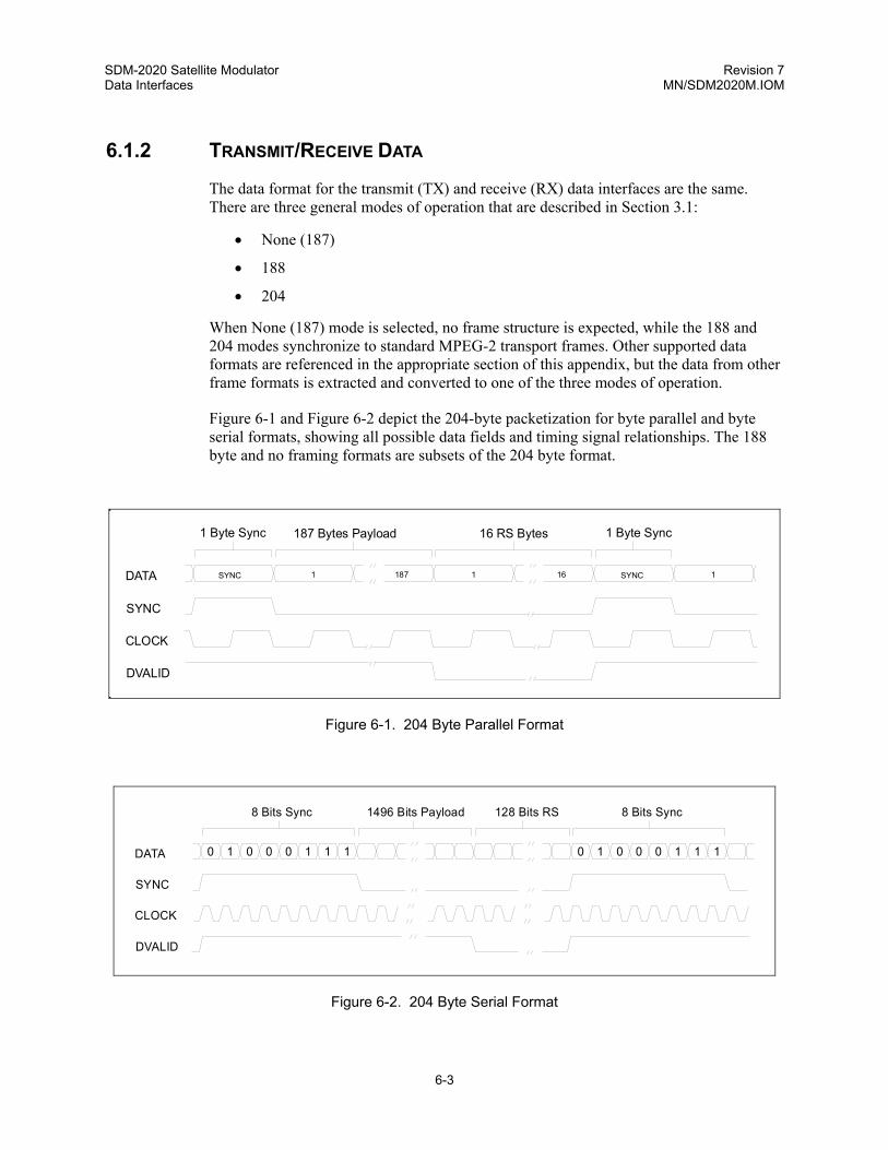
SDM-2020 Satellite Modulator Revision 7 Data Interfaces MN/SDM2020M.IOM
6-3
6.1.2 TRANSMIT/RECEIVE DATA
The data format for the transmit (TX) and receive (RX) data interfaces are the same. There are three general modes of operation that are described in Section 3.1:
• None (187)
• 188
• 204
When None (187) mode is selected, no frame structure is expected, while the 188 and 204 modes synchronize to standard MPEG-2 transport frames. Other supported data formats are referenced in the appropriate section of this appendix, but the data from other frame formats is extracted and converted to one of the three modes of operation.
Figure 6-1 and Figure 6-2 depict the 204-byte packetization for byte parallel and byte serial formats, showing all possible data fields and timing signal relationships. The 188 byte and no framing formats are subsets of the 204 byte format.
1 Byte Sync 1 Byte Sync187 Bytes Payload
SYNC
DATA
DVALID
CLOCK
SYNC 1 SYNC 1187 1 16
16 RS Bytes
Figure 6-1. 204 Byte Parallel Format
0 1 0 0 10 1 1
8 Bits Sync 1496 Bits Payload
SYNC
DATA
DVALID
CLOCK
0 1 0 0 10 1 1
8 Bits Sync128 Bits RS
Figure 6-2. 204 Byte Serial Format

SDM-2020 Satellite Modulator Revision 7 Data Interfaces MN/SDM2020M.IOM
6-4
Note: For proper operation, data and timing must be continuous, and meet the described criteria as
specified in Figure 6-1, Figure 6-2, and Table 6-2.
Table 6-2. 204 Data and Timing
DATA Payload data is byte parallel, where DATA 7 is the most significant bit; or byte serial, where data is applied to DATA 7 with the most significant bit preceding the least.
For 188 and 204 format, the payload is 187 bytes in length, preceded by a sync word. In the 204-byte mode, the payload is followed by 16 bytes of reed-Solomon data, or 16 filler bytes.
CLOCK The clock is at the bit or byte rate in accordance with serial or parallel mode. The rising edge of the clock is centered on the data.
SYNC SYNC timing depends upon the selection made for DVB FRAMING TYPE in the Configuration Interface menu
DVB Framing Type SYNC
188 or 204 The SYNC timing is derived from either the EXT SYNC or CORR ON DATA selection from the Configuration Interface menu. See the TX SYNC SELECT command, Appendix A.
None The SYNC signal is ignored.
For the 188 or 204 byte framing modes, either a SYNC pulse or SYNC byte of value 47h is required, dependent on the modulator configuration. Both may be applied, with only one having effect, dependent upon configuration. When used, the SYNC pulse is active high centered over the SYNC word. In parallel operation, it is one byte clock width. In serial operation, the modulator recognizes the SYNC pulse centered on the entire SYNC bit (8 clocks wide), or centered on the most significant bit of the byte (1 clock wide).
DVALID Although this signal is identified by both DVB and DBS formats, it is not used by the modulator.

SDM-2020 Satellite Modulator Revision 7 Data Interfaces MN/SDM2020M.IOM
6-5
This page is intentionally left blank.
7-1
Chapter 7. RS-422 PARALLEL/SERIAL INTERFACE
7.1 GENERAL
This interface operates at RS-422 signal levels. It accommodates a variety of MPEG-2 framing formats and EIA-530 serial data.
7.1.1 APPLICABLE DOCUMENTS
TM1449 Interfaces for CATV/SMATV Headends and Similar Professional Equipment
TIA/EIA-644 Telecommunications Industry Standard, Electrical Characteristics Of Low Voltage Differential Signaling (LVDS) Interface Circuits (originally Standards Proposal SP-3357)
RS-422 Electrical Characteristics of Balanced Voltage Digital Interface Circuits
EIA-530 High Speed 25-Position Interface for Data Circuit - Terminating Equipment
7.1.2 DESCRIPTION
The RS-422 interface has two data connectors and an auxiliary connector supporting various operating modes.
• J3 Parallel/Serial DVB Connector (25-pin D, female):
• Parallel mode – In this mode, the interface behaves like a DVB parallel synchronous interface, but with RS-422 levels. The input is at the byte rate.
• Serial mode – An alternate form of operation is possible, where the MSB is used for serial input at the bit rate.
• J4 Serial EIA-530 Connector (25-pin D, female):
• Serial mode only – RS-422 levels with pinout and operation per EIA-530 at a serial clock rate.

SDM-2020 Satellite Modulator Revision 7 RS-422 Data Interface MN/SDM2020M.IOM
7-2
• J5 Auxiliary Connector (9-pin D, female):
• Provides an additional ST Clock (output), plus open collector fault signals.
The appropriate interface control is automatically enabled when the interface module is installed in the modulator. The plug-in data interface is programmable for serial or parallel operation from either the front panel keypad or the remote port on the rear panel.
The following cables, or an equivalent computer grade cable incorporating twisted, shielded pairs, are recommended:
• Belden type LV Computer M9768
• Belden 8175
The Belden 8175 has a lower capacitance, however it has a larger diameter and requires the selection of an appropriate connector shell.
The typical cable length for the serial/parallel interfaces is ≤ 5 meters (16.405 feet).
The interface operates to the specifications described in Table 7-1.
Table 7-1. RS-422 Interface Specifications
General Specifications
Interface Type RS-422/EIA-530 Synchronous, Serial/Parallel.
Data Rate 1.5 to 18 Mbit/s, serial.
1.5 to 100 Mbit/s, parallel
Data Framing Formats
188, 204 byte packets per ETS 300 421, and None.
Connectors 25-pin, female D for serial data.
25-pin, female D for parallel data.
9-pin, female D for reference clock from unit (modulator only), plus fault.
Electrical Properties Per RS-422.
Parallel Signal Types
TX: TX Clock, TX Data, Data Valid, and Sync per TM1449.
The modulator does not require Sync or Data Valid with the 188 or 204 byte patterns.
Parallel: RX Clock, RX Data, Data Valid, and Sync per TM1449
Reference (ST equivalent).
Serial Signal Types Serial: SD, ST, TT, RS, CS, RD, RT, RR (CD).
Voltage Level 4 ± 2V differential into 100Ω.
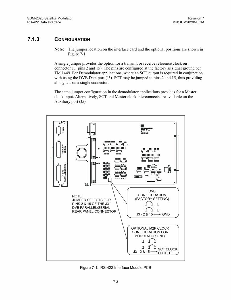
SDM-2020 Satellite Modulator Revision 7 RS-422 Data Interface MN/SDM2020M.IOM
7-3
7.1.3 CONFIGURATION
Note: The jumper location on the interface card and the optional positions are shown in Figure 7-1.
A single jumper provides the option for a transmit or receive reference clock on connector J3 (pins 2 and 15). The pins are configured at the factory as signal ground per TM 1449. For Demodulator applications, where an SCT output is required in conjunction with using the DVB Data port (J3). SCT may be jumped to pins 2 and 15, thus providing all signals on a single connector.
The same jumper configuration in the demodulator applications provides for a Master clock input. Alternatively, SCT and Master clock interconnects are available on the Auxiliary port (J5).
D
OPTIONAL M2P CLOCKCONFIGURATION FOR
MODULATOR ONLY
VBCONFIGURATION
(FACTORY SETTING)
J3 D
VB P
AR
ALL
EL/S
ERIA
LJ4
EIA
-530
SER
IAL
J5 A
UX
J
J
3
3
-
-
2
2
&
&
1
1
5
5
G
SCT CLOCKOUTPUT
ND
NOTE:JUMPER SELECTS FORPINS 2 & 15 OF THE J3DVB PARALLEL/SERIALREAR PANEL CONNECTOR
Figure 7-1. RS-422 Interface Module PCB

SDM-2020 Satellite Modulator Revision 7 RS-422 Data Interface MN/SDM2020M.IOM
7-4
7.1.4 USER INTERFACES
The following paragraphs describe the RS-422 user interfaces.
7.1.4.1 PARALLEL, J3, DB25 FEMALE (DVB PARALLEL/SERIAL DATA INTERFACE)
This data port supports DVB and DBS parallel and serial packetized data. There are three standard frame formats supported, as follows:
• None, no framing byte format: Continuous serial or parallel payload data with no framing information.
• 188 byte format:
• Serial or parallel data, (1 sync byte + 187 payload bytes).
• 204 byte format:
• Serial or parallel data, (1 sync byte + 187 payload bytes + 16 bytes for Reed-Solomon coding).
Figure 7-1 and Figure 7-2 depict the 204-byte packetization for byte parallel and byte serial formats, showing all possible data fields and timing signal relationships.
The 188 byte and no framing formats are subsets of the 204 byte format.
7.1.4.1.1 Connector Pinout, J3, Parallel/Serial DVB
The connector is a sub-miniature, 25-pin, female D connector, with threaded jack nuts (refer to Table 7-2 for pinout). All signals on this connector are inputs to the modulator, except the signal pair on pins 2 and 15 when the jumper is selected for SCT output.
When used as a serial data port, Data 7 (pins 3 and 16) are the active data pins. Signal assignments for pins 2 and 15 are jumper-selectable. They are defined as signal ground in the DVB definition of TM1449, but may be configured to provide SCT out.
Signal levels are as defined in RS-422. Per TM1449, the differential sense of all signal pairs is a logic “1” when “A” is positive with respect to “B.” This is the normal selection in the Configuration Interface menu.
The same jumper provides the option for a TX or RX reference clock on connector J3 (pins 2 and 15). The pins are configured at the factory as signal ground per TM 1449. For modulator applications where an SCT output is required in conjunction with using the DVB Data port (J3), SCT may be jumped to pins 2 and 15, thus providing all signals on a single connector.
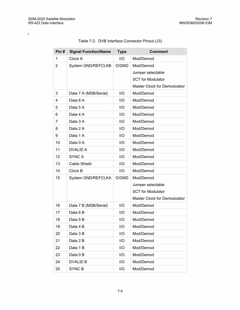
SDM-2020 Satellite Modulator Revision 7 RS-422 Data Interface MN/SDM2020M.IOM
7-5
Table 7-2. DVB Interface Connector Pinout (J3)
Pin # Signal Function/Name Type Comment
1 Clock A I/O Mod/Demod
2 System GND/REFCLKB
O/GND Mod/Demod
Jumper selectable
SCT for Modulator
Master Clock for Demodulator
3 Data 7 A (MSB/Serial) I/O Mod/Demod
4 Data 6 A I/O Mod/Demod
5 Data 5 A I/O Mod/Demod
6 Data 4 A I/O Mod/Demod
7 Data 3 A I/O Mod/Demod
8 Data 2 A I/O Mod/Demod
9 Data 1 A I/O Mod/Demod
10 Data 0 A I/O Mod/Demod
11 DVALID A I/O Mod/Demod
12 SYNC A I/O Mod/Demod
13 Cable Shield I/O Mod/Demod
14 Clock B I/O Mod/Demod
15 System GND/REFCLKA
O/GND Mod/Demod
Jumper selectable
SCT for Modulator
Master Clock for Demodulator
16 Data 7 B (MSB/Serial) I/O Mod/Demod
17 Data 6 B I/O Mod/Demod
18 Data 5 B I/O Mod/Demod
19 Data 4 B I/O Mod/Demod
20 Data 3 B I/O Mod/Demod
21 Data 2 B I/O Mod/Demod
22 Data 1 B I/O Mod/Demod
23 Data 0 B I/O Mod/Demod
24 DVALID B I/O Mod/Demod
25 SYNC B I/O Mod/Demod
CL OCKC ONFI GURA TIONMOD ULATO RDEMO DULA TORJ3 - 2 & 15 SCT C LOCK OUTJ3 - 2 & 15 M ASTE R CL OCK I
DV BCO NFIG URAT ION(FA CTOR Y SET TING)
J3 - 2 & 1 5 GNDJUM PER S ELEC TFOR J3 PI N 2 & 15RS-4 22
J3 PARALLELJ4 SERIAL
J5 AUX

SDM-2020 Satellite Modulator Revision 7 RS-422 Data Interface MN/SDM2020M.IOM
7-6
7.1.4.2 SERIAL, J4, DB25 FEMALE (EIA-530 SERIAL DATA INTERFACE)
This interface has no provision for SYNC or DVALID signals. If framing is desired, a sync byte (47 hex) is imbedded into the data stream every 188 or 204 bytes, as selected in the modulator configuration. The modulator detects the sync byte and formats the serial interface data into a standard, error-protected 204-byte packet.
7.1.4.2.1 Connector Pinouts, J4, EIA-530
The connector is a subminiature, 25-pin, female D connector, with threaded jack nuts. Signal functions are as defined in EIA-530.
The differential sense of all signals is logic “1” when “B” is positive with respect to “A” as defined in EIA-530. Only those pins indicated as “modulator” in the table are applicable.
Table 7-3. EIA-530 Serial Interface Connector Pinout (J4)
Pin # Signal Function Name Type Comment 1 530 Shield Shield Mod/Demod 2 Transmit Data (TD-A) BA-A I Modulator 3 Receive Data (RD-A) BB-A O Demodulator 4 Request To Send (EIA-A) CA-A I Modulator 5 Clear To Send (CS-A) CB-A O Modulator 6 DCE Ready (DM-A) CC-A O Demodulator 7 Signal Ground AB GND 8 Receive Line Signal Detect (RR-A) CF-A O Demodulator 9 Receive Timing (RT-B) DD-B O Demodulator 10 Receive Line Signal Detect (RR-B) CF-B O Demodulator 11 Terminal Timing (TT-B) DA-B I Modulator 12 Send Timing (ST-B) DB-B O Modulator 13 Clear To Send (CS-B) CB-B O Modulator 14 Transmit Data (TD-B) BA-B I Modulator 15 Send Timing (ST-A) DB-A O Modulator 16 Receive Data (RD-B) BB-B O Demodulator 17 Receive Timing (RT-A) DD-A O Demodulator 18 N/C 19 Request To Send (EIA-B) CA-B I Modulator 20 Master Clock (MC-A) N/A I Demodulator 21 Demodulator Fault (DF) N/A O Demodulator 22 DCE Ready (DM-B) CC-B O Demodulator 23 Master Clock (MC-B) N/A I Demodulator 24 Terminal Timing (TT-A) DA-A I Modulator 25 Modulator Fault (MF) N/A O Modulator

SDM-2020 Satellite Modulator Revision 7 RS-422 Data Interface MN/SDM2020M.IOM
7-7
7.1.4.3 AUXILIARY, J5
This port provides for other modem-specific signals not otherwise defined for either or both of the two data connectors.
7.1.4.3.1 Connector Pinout, J5
The connector is a sub-miniature, 9-pin, female D connector, with threaded jack nuts (refer to Table 7-4 for connector pinout). Differential pairs are RS-422 compatible.
Note: The sense of differential signal pairs is a logic “1” when “B” is positive with respect to “A”.
Single-ended signals (MF and DF fault signals) are open collector where:
Voh=12V max. and Vol=0.5V max. @ Iol=8 ma.
A pull-up resistor external to the equipment is required.
The fault signals, MF and DF, operate as follows: A fault is indicated by an “OFF” collector (high) and OK status is indicated by an “ON” collector (low).
Table 7-4. Auxiliary Connector Pinout (J5)
Pin # Signal Function Name Type Comment
1 GND Signal Ground
2 Demod Fault Indicator
DF I Demodulator Summary Fault
Redundancy switch application
3 Send Timing ST-A O Modulator
SCT for terrestrial synchronization
4 N/C
5 Master Clock MC-B I Demodulator
6 Mod Fault Indicator MF O Modulator Summary Fault
Redundancy switch application
7 Carrier Detect /CD O Demodulator
8 Send Timing ST-B O Modulator
SCT for terrestrial synchronization
9 Master Clock MC-A I Demodulator

SDM-2020 Satellite Modulator Revision 7 RS-422 Data Interface MN/SDM2020M.IOM
7-8
7.1.5 RS-422 INTERFACE FRONT PANEL MENUS
Refer to Chapter 5, Utility Interface Menu. If the RS-422 interface module is installed, the Utility Interface menu displays commands specific to that interface.
7.1.6 RS-422 INTERFACE REMOTE CONTROL COMMANDS
Refer to Appendix A.

8-1
Chapter 8. LOW VOLTAGE DIFFERENTIAL SIGNAL (LVDS)
8.1 GENERAL
The following paragraphs describe the LVDS interface. This plug-in module provides the physical and electrical interface between an SDM-2020 modulator or demodulator and DVB or DBS signal sources operating with LVDS electrical characteristics.
8.1.1 APPLICABLE DOCUMENTS
TM1449 Interfaces for CATV/SMATV Headends and Similar Profession
TIA/EIA-644 Telecommunications Industry Standard, Electrical CharacterisVoltage Differential Signaling (LVDS) Interface Circuits (originProposal SP-3357)
8.1.2 DESCRIPTION
The LVDS interface has dedicated transmit and receive connectors and an auxiliary connector. The Receive Out connector is used with the demodulator while the Transmit In connector is used with the modulator:
• J3 Receive Out connector (25-pin D, female). This connector supports the following data formats:
Parallel format: The interface is a DVB 8-bit parallel synchronous interface. Data and clock exit the connector and the output clock (Clock A and Clock B) is at the byte rate.
Serial format: MSB (Data7) is used for serial output data and the output clock (Clock A and Clock B) is at the bit rate.

SDM-2020 Satellite Modulator Revision 7 Low Voltage Differential Signal (LVDS) MN/SDM2020M.IOM
8-2
• J4 Transmit In connector (25-pin D, female):
Parallel format: The interface is a DVB 8-bit parallel synchronous interface. Data and clock are input to the connector and the input clock (Clock A and Clock B) is at the byte rate.
Serial format: MSB (Data7) is used for serial input data and the input clock (Clock A and Clock B) is at the bit rate.
• J5 Auxiliary connector (9-pin D, female):
Provides TX and RX clock references and open collector fault signals.
The TX In or RX Out interface is automatically enabled when the interface module is installed in the modulator or demodulator. The plug-in data interface is programmable for serial or parallel operation from either the front panel keypad or the remote port on the rear panel.
The following cables, or an equivalent computer grade cable incorporating twisted, shielded pairs, are recommended:
• Belden type LV Computer M9768
• Belden 8175
The Belden 8175 has a lower capacitance, however it has a larger diameter and requires the selection of an appropriate connector shell.
The typical cable length for the serial/parallel interfaces is ≤ 5 meters (16.405 feet). The interface operates to the specifications described in Table 8-1.
Table 8-1. LVDS Specifications
General Specifications
Interface Type LVDS/DVB Synchronous, Serial/Parallel.
Data Rate 1.5 to 32 Mbit/s, serial.
1.5 to 100 Mbit/s, parallel.
Data Framing Formats 188, 204 byte packets per ETS 300 421, and None.
Connectors 25-pin D female for TX data.
25-pin D female for RX data.
9-pin D female for reference clocks plus faults.
Electrical Properties Per TIA/EIA-644.

SDM-2020 Satellite Modulator Revision 7 Low Voltage Differential Signal (LVDS) MN/SDM2020M.IOM
8-3
Table 8-1. LVDS Specifications (Continued)
General Specifications
Signal Types TX: TX Clock, TX Data, Data Valid, and Sync per TM1449.
The modulator does not require Sync or Data Valid with the 188 or 204 b
Voltage Levels 290 ± 40 mV differential into 100Ω.
8.1.3 CONFIGURATION
The interface provides DVB compliant operation when pins 2 and 15 are grounded using the “DVB Configuration” jumper settings as described in the following paragraphs. A reference clock from the modulator is output from the connector (J4) when the jumpers are selected for SCT Output operation. See jumpers J1 and J6.
Note: SCT clock is always available on the Auxiliary Connector J5 and requires no jumper settings.
In a demodulator, the LVDS interface (J3) only has provision for DVB Configuration, and the Master Clock Input is not used. See jumpers J2 and J7.
J3 R
ECEI
VE O
UTJ4
TR
ANS
MIT
INJ5
AU
X
DEMODULATORDVB
CONFIGURATION(FACTORY SETTING)
3
2
1
3
2
1
J2 J7
MODULATOR
DVBCONFIGURATION
(FACTORY SETTING)
3
2
1
3
2
1
J1 J6
J4 - 2 & 15 SCT CLOCK OUTPUT
CLOCKCONFIGURATION
J1 J63
2
1
3
2
1
J1 J6
J2 J7
Figure 8-1. LVDS Interface Module PCB

SDM-2020 Satellite Modulator Revision 7 Low Voltage Differential Signal (LVDS) MN/SDM2020M.IOM
8-4
8.1.4 RECEIVE/TRANSMIT DATA, J3/J4, DB25 FEMALE
The receive transmit data interfaces have the same formats. There are three general modes of operation controlled via the front panel display/keypad or the remote port. The standard frame formats supported are as follows:
• 188 Mode: The unit seeks a DVB/MPEG2 frame consisting of 1 sync byte (047 hex) and 187 bytes of data. The frame structure is acquired, and 16 bytes of Reed-Solomon check bytes are added by the modulator to create a satellite frame of 204 bytes. The 16 bytes are removed by the demodulator and the 188-byte frame returned to the terrestrial circuit.
• 204 Mode: A 204-byte frame structure consisting of 1 sync byte (047 hex) plus 187 bytes of data and 16 bytes reserved for check bytes is expected. The modulator acquires the frame structure and fills the Reed-Solomon bytes into the 16 reserved bytes, again resulting in a 204-byte satellite frame. The demodulator returns the 204-byte frame to the terrestrial circuit.
• None: In this mode, no incoming frame structure is expected, and the modulator creates one. A sync byte (047 hex) is created, followed by 187 bytes of data plus 16 Reed-Solomon check bytes. The resulting satellite frame is 204 bytes. The demodulator removes the 16 Reed-Solomon bytes and the sync byte and returns the data to the terrestrial circuit.
Figure 6-1 and Figure 6-2 depict the 204-byte packetization for byte parallel and byte serial formats at J3 and J4, showing all possible data fields and timing signal relationships.
The 188-byte and no framing formats are subsets of the 204-byte format.
8.1.4.1 CONNECTOR PINOUTS J3
The connector is a 25-pin sub-miniature D female, with threaded jack nuts. All signals for this connector are outputs to the demodulator, except the signal pair on pins 2 and 15 (for an exception; see jumper settings). When used as a serial data port, Data 7 (pins 3 and 16) are the active data pins. For DVB parallel operation Data 7 through Data 8 are used.
Signal levels are as defined in TIA/EIA-644. Per TM1449, the differential sense of all signal pairs is a logic “1” when “A” is positive with respect to “B”. This is the normal selection in the Configuration Interface menu. For DBS applications, the polarity of signals may be inverted from the Configuration Interface menu.

SDM-2020 Satellite Modulator Revision 7 Low Voltage Differential Signal (LVDS) MN/SDM2020M.IOM
8-5
Table 8-2. DVB Interface Connector Pinout, J3 RX Out (Demodulator Only)
Pin # Signal Function/Name Type Comment
1 Clock A O Demod
2 System GND/REFCLKB I/GND Demod,
LVDS Interface - N/A, jumper on GND only
3 Data 7 A(MSB/Serial) O Demod
4 Data 6 A O Demod
5 Data 5 A O Demod
6 Data 4 A O Demod
7 Data 3 A O Demod
8 Data 2 A O Demod
9 Data 1 A O Demod
10 Data 0 A O Demod
11 DVALID A O Demod
12 SYNC A O Demod
13 Cable Shield O Demod
14 Clock B O Demod
15 System GND/REFCLKA
I/GND Demod,
LVDS Interface - N/A, jumper on GND only
16 Data 7 B (MSB/Serial) O Demod
17 Data 6 B O Demod
18 Data 5 B O Demod
19 Data 4 B O Demod
20 Data 3 B O Demod
21 Data 2 B O Demod
22 Data 1 B O Demod
23 Data 0 B O Demod
24 DVALID B O Demod
25 SYNC B O Demod

SDM-2020 Satellite Modulator Revision 7 Low Voltage Differential Signal (LVDS) MN/SDM2020M.IOM
8-6
8.1.4.2 CONNECTOR PINOUTS J4
The connector is a 25-pin sub-miniature D female, with threaded jack nuts for connector pinout). All signals for this connector are inputs to the modulator, except the signal pair on pins 2 and 15 (for an exception; see jumper settings). When used as a serial data port, Data 7 (pins 3 and 16) are the active data pins. For DVB parallel operation Data 7 through Data 8 are used.
Signal levels are as defined in TIA/EIA-644. Per TM1449, the differential sense of all signal pairs is a logic “1” when “A” is positive with respect to “B”. This is the normal selection in the Configuration Interface menu. For DBS applications, the polarity of signals may be inverted from the Configuration Interface menu.
Table 8-3. DVB Interface Connector Pinout, J4 TX IN
Pin # Signal Function/Name Type Comment 1 Clock A I Mod 2 System GND/REFCLKB O/GND Mod,
Jumper selectable SCT output for Modulator
3 Data 7 A (MSB/Serial) I Mod 4 Data 6 A I Mod 5 Data 5 A I Mod 6 Data 4 A I Mod 7 Data 3 A I Mod 8 Data 2 A I Mod 9 Data 1 A I Mod 10 Data 0 A I Mod 11 DVALID A I Mod, Modulator Ignores 12 SYNC A I Mod 13 Cable Shield I Mod 14 Clock B I Mod 15 System GND/REFCLKA
O/GND Mod/Demod
Jumper selectable SCT output for Modulator
16 Data 7 B (MSB/Serial) I Mod 17 Data 6 B I Mod 18 Data 5 B I Mod 19 Data 4 B I Mod 20 Data 3 B I Mod 21 Data 2 B I Mod 22 Data 1 B I Mod 23 Data 0 B I Mod 24 DVALID B I Mod 25 SYNC B I Mod

SDM-2020 Satellite Modulator Revision 7 Low Voltage Differential Signal (LVDS) MN/SDM2020M.IOM
8-7
8.1.5 AUXILIARY, J5
This port provides for other modem-specific signals not otherwise defined on the data connectors.
8.1.5.1 CONNECTOR PINOUT J5
The connector is a sub-miniature, 9-pin D female, with threaded jack nuts. Differential pairs are LVDS compatible.
Note: The sense of differential signal pairs is a logic “1” when “B” is positive with respect to “A.”
Single-ended signals are open collector where:
Voh=12V max. and Vol=0.5V max. @ Iol=8 ma.
A pull-up resistor external to the equipment is required. The fault signals, MF and DF, operate as follows: A fault is indicated by an “OFF” collector (high) and OK status is indicated by an “ON” collector (low).
Table 8-3. Auxiliary Connector Pinout
Pin # Signal Function Name Type Comment 1 GND Signal Ground 2 Demod Fault Indicator DF O Demodulator Summary Fault
Redundancy switch application 3 Send Timing ST-A O Modulator
SCT for terrestrial synchronization 4 N/C 5 Master Clock MC-B I Demodulator 6 Mod Fault Indicator MF O Modulator Summary Fault
Redundancy switch application 7 Carrier Detect /CD O Demodulator 8 Send Timing ST-B O Modulator
SCT for terrestrial synchronization 9 Master Clock MC-A I Demodulator
8.1.6 LVDS INTERFACE FRONT PANEL MENUS
Refer to Chapter 5, Utility Interface menu.
8.1.7 LVDS REMOTE INTERFACE COMMANDS
Refer to Appendix A.

SDM-2020 Satellite Modulator Revision 7 Low Voltage Differential Signal (LVDS) MN/SDM2020M.IOM
8-8
This page is intentionally left blank.

9-1
Chapter 9. ASI/RS-422 DATA INTERFACE
9.1 ASI/RS-422 (ASYNCHRONOUS SERIAL INTERFACE AND SERIAL DATA INTERFACE
The following paragraphs describe the ASI/RS-422 Data Interface.
9.1.1 APPLICABLE DOCUMENTS
Applicable specifications, as referenced herein, include:
TM1449 Interfaces for CATV/SMATV Headends and Similar
Professional Equipment
RS-422 Electrical Characteristics of Balanced Voltage Digital Interface Circuits
EIA-530 High Speed 25-Position Interface for Data Circuit - Terminating Equipment
ETS 300 421 Digital Broadcasting Systems For Television, Sound And Data Services; Framing Structure, Channels Coding And Modulation For 11/12 GHz Services
9.1.2 DESCRIPTION
This data interface is a plug-in module that inserts into the rear of the SDM-2020 Modulator or SDM-2020 Demodulator chassis. It provides physical and electrical connection between the external terrestrial circuit and the internal circuitry of the modulator or demodulator. The plug-in interface has full duplex capability, but is automatically configured for simplex-transmit or simplex-receive operation.
The ASI/RS-422 interface combines two electrical and physical interfaces into a single assembly. The ASI section provides DVB-compliant interface with BNC connectors, while the RS-422 section supports serial communications through a standard 25-pin D connector per EIA-530. Operation for either ASI or RS-422 is selected by programming the unit from the front panel keypad/LCD or from the remote port. Only one of the interface types is active at a time.

SDM-2020 Satellite Modulator Revision 7 ASI/RS-422 Data Interface MN/SDM2020M.IOM
9-2
Figure 9-1. ASI/RS-422 Interface Block Diagram
J3J4
J5J6
J7
ASI I
NPU
TS
EIA-
422/
530
ASI O
UTP
UTS
Figure 9-2. ASI Module Assembly
ASIRECOVERY
J3
J4
RECOVERY,
PROCESSING
AND
ASI/EIA
SELECTION
SD
TT
ST
RS
CS
RR
RD
RT
J6
J5
J7ASI
GENERATOR
LOOPBACK LEVELTRANSLATORS
M&C
MODULATOR/DEMODULATORINTERFACETERRESTRIAL
INTERFACE
TXASI
RXASI
BNC-F
BNC-F
DCPOWER
DM
EIA

SDM-2020 Satellite Modulator Revision 7 ASI/RS-422 Data Interface MN/SDM2020M.IOM
9-3
A 75Ω coaxial cable (Belden 8281 or equivalent) is recommended for all ASI connectors. Typical coaxial cable length is up to 140 meters (460 feet) with good quality coaxial cable. Typical attenuation of up to 18 dB at 270 MHz is permitted. The following cables, or an equivalent computer grade cable incorporating twisted, shielded pairs, are recommended for the RS-422 interface:
• Belden type LV Computer M9768
• Belden 8175
The Belden 8175 has a lower capacitance, however it has a larger diameter and requires the selection of an appropriate connector shell. The typical cable length for the serial/parallel interfaces is ≤ 5 meters (16.405 feet).
The interface operates to the specifications described in Table 9-1.
Table 9-1. ASI/RS-422 Specifications
General Specifications Data Framing Formats 188, 204 byte packets per ETS 300 421, and None. Hot Pluggable Not required. Unit power is turned off before removal or insertion of the
data interface. ASI Specifications
Data Rate 1.5 to 100 Mbit/s ASI. Clock Rate Uncertainty Programmed data rate ± 100 ppm. Transport Clock ASI The transport rate is 270 Mbit/s for all data rates. Impedance 75Ω. Return Loss 15 dB, frequencies, 5 to 270 MHz. Loop Functions (see Note 1)
Loopback Loop Thru
Connectors BNC female, 75Ω. Electrical Properties Per TM 1449. Packet Types Burst or distributed. Signal Types Serial data. Voltage Level 800 mV ± 10% into 75Ω. ASI Data Loop 3 dB Cutoff Frequency
2 Hz (see Note 2)
Jitter Tolerance Meets ITU-T G.823 (3/93) and ITU-T G.824 (3/93) Jitter Transfer ≤ 0.5 dB peaking up to cutoff frequency.
–20 dB per decade beyond cutoff. Cable Length, Typical
Rev. – Rev. A
RG59 50 m 100 m
Belden 8281 70 m 140 m
RS-422 Specifications Data Rate 1.5 to 18 Mbit/s, serial RS-422. Clock Rate Uncertainty Programmed data rate ± 100 ppm. Connectors 25-pin D female per EIA-530. Electrical Properties Per RS-422.

SDM-2020 Satellite Modulator Revision 7 ASI/RS-422 Data Interface MN/SDM2020M.IOM
9-4
Table 9-1. ASI/RS-422 Specifications (Continued)
RS-422 Specifications Signal Types
SD, TT, ST, RD, RT, RS, RR, CS, DM, and MC. Data synchronization is detected by correlating the data stream for the MPEG2 sync pattern per ETS 300 421.
Voltage Level
4 ± 2V differential into 100Ω.
Notes:
1. Loopback – The yellow TEST MODE LED is illuminated when Loopback is turned ON. During Loopback input data is looped back to the terrestrial data output connector(s) and data continues into the modulator. Loop Thru – Operation is nearly identical to Loopback, except the yellow LED is not illuminated. Conceptually, the data output is operating as a monitor point.
2. Rev. A or later assemblies include this capability. Rev dash (-) assemblies can be upgraded to this capability.
9.1.3 TRANSMIT INPUT CONNECTORS, J3/J4, BNC, FEMALE
These two connectors accept TX data from the terrestrial interface. By default, J3 is enabled and J4 is disabled. The active input is user programmable and maintained in non-volatile memory of the modulator or demodulator chassis. Both connectors are terminated into 75Ω whether selected or not selected.
9.1.4 RS-422 CONNECTOR, J5, 25-PIN D, FEMALE
This connector is compatible with EIA-530 operation and pinout. It is a serial interface with RS-422 signals plus the TTL-OC fault signals indicating the status of the modulator or demodulator.
9.1.4.1 CONNECTOR PINOUT J5
The connector is a 25-pin, female, D type, with threaded jack nuts.
Notes:
1. RS-422 signal levels are as defined in RS-422.
2. The differential sense of all signal pairs is a logic “1” when “A” is negative with respect to “B.”
Single-ended signals (MF and DF fault signals) are open collector where:

SDM-2020 Satellite Modulator Revision 7 ASI/RS-422 Data Interface MN/SDM2020M.IOM
9-5
Voh=12V max. and Vol=0.5V max. @ Iol=8 ma.
A pull-up resistor external to the equipment is required. The fault signals, MF and DF, operate as follows: A fault is indicated by an “OFF” collector (high) and OK status is indicated by an “ON” collector (low).
Table 9-2. RS-422 Connector Pinout (Per EIA-530), J5
Pin # Signal Function Name Type Comment
1 530 Shield Shield Mod/Demod
2 Transmit Data (TD-A) BA-A I Modulator
3 Receive Data (RD-A) BB-A O Demodulator
4 Request To Send (EIA-A) CA-A I Modulator
5 Clear To Send (CS-A) CB-A O Modulator
6 DCE Ready (DM-A) CC-A O Demodulator
7 Signal Ground AB GND
8 Receive Line Signal Detect (RR-A) CF-A O Demodulator
9 Receive Timing (RT-B) DD-B O Demodulator
10 Receive Line Signal Detect (RR-B) CF-B O Demodulator
11 Terminal Timing (TT-B) DA-B I Modulator
12 Send Timing (ST-B) DB-B O Modulator
13 Clear To Send (CS-B) CB-B O Modulator
14 Transmit Data (TD-B) BA-B I Modulator
15 Send Timing (ST-A) DB-A O Modulator
16 Receive Data (RD-B) BB-B O Demodulator
17 Receive Timing (RT-A) DD-A O Demodulator
18 N/C
19 Request To Send (EIA-B) CA-B I Modulator
20 DTE Ready (MC-A) CD-A I
21 Demodulator Fault (DF) DF O Demodulator
22 DCE Ready (DM-B) CC-B O Demodulator
23 DTE Ready (MC-B) CD-B I
24 Terminal Timing (TT-A) DA-A I Modulator
25 Modulator Fault (MF) MF O Modulator
SDM-2020 Satellite Modulator Revision 7 ASI/RS-422 Data Interface MN/SDM2020M.IOM
9-6
9.1.5 RECEIVE OUTPUT CONNECTORS, J6/J7, BNC, FEMALE
Duplicate signals exit both of these connectors on the demodulator to deliver receive data to the terrestrial interface. J6 and J7 are both active at all times, no selection is required.
9.1.6 ASI/RS-422 INTERFACE FRONT PANEL MENUS
Refer to Chapter 5, Utility Interface menu.
9.1.7 ASI/RS-422 REMOTE INTERFACE COMMANDS
Refer to Appendix A.

10-1
Chapter 10. ECL/HSSI DATA INTERFACE
10.1 GENERAL
The following paragraphs describe the ECL/HSSI interface. This plug-in module provides the physical and electrical interface between an SDM-2020 Modulator or Demodulator and a serial ECL signal source operating with TIA/EIA-612 electrical characteristics.
10.1.1 APPLICABLE DOCUMENTS
DBS-PS-007 DBS Development and Fabrication Project
ETS 300 421 Digital broadcasting systems for television, sound and data services
TM1449 Interfaces for CATV / SMATV Headends and Similar Professional Equipment, 10th Working Draft
TIA/EIA-612 Electrical Characteristics for an Interface at Data Signaling Rates up to 52 Mbit/s (HSSI)
TIA/EIA-613 High Speed Serial Interface for Data Terminal Equipment and Data Circuit-Terminating Equipment (HSSI)
Cisco HSSI spec HSSI High Speed Serial Interface Design Specification, Rev. 3.0
ISO/IEC DIS 13818-1 Coding of moving pictures and associated audio
10.1.2 DESCRIPTION
The ECL/HSSI data interface is a plug-in option that is field-installed from the rear of the SDM-2020 chassis, and provides the Modulator and Demodulator with an emitter coupled logic (ECL) serial data electrical interface.
This document defines the SDM-2020 Modem Interface along with the ECL/HSSI Interface as the DCE (Data Communications Equipment), and the Terrestrial (user data interface) as the DTE (Data Terminal Equipment). Transmit data enters the ECL/HSSI Interface and received data exits it.

SDM-2020 Satellite Modulator Revision 7 ECL/HSSI TX MN/SDM2020M.IOM
10-2
10.1.3 ECL/HSSI DATA INTERFACE SPECIFICATION SUMMARY Terrestrial (User) Data Interface:
Type
Data Rate
Signals Supported
Electrical Connector
Synchronous serial 1.5 to 70 Mbit/s RT, RD, ST, TT, SD, TA, CA, LA, LB, LC, TM, TPSYNC, TDVALID, CD, DF, MF, RPSYNC, RDVALIDPer EIA-612 (10KH ECL) 50-pin mini-D female per EIA-613 (HSSI)
Framing Format Compatibility
TM1449 (DVB) DBS (1.5 to 32 Mbit/s only) No Framing
10.1.4 TERRESTRIAL (USER) DATA INTERFACE
10.1.4.1 TERRESTRIAL TRANSPORT PROTOCOLS
The Demodulator/Modulator is compatible with TM1449 transfer of MPEG-2 data signals in the standardized transport layer format. The Demodulator/Modulator also supports DBS (DBS-PS-007) no framing (187 bytes) format modes (Table 10-1).
Table 10-1 summarizes the primary characteristics of each transport protocol. The SDM-2020 was designed to comply with these primary interface standards, however; custom interfaces can be supported as outlined in the data transfer modes definition section of this document.
Table 10-1. Framing Format Summary
Framing Format Summary
Transport Protocol
Transport Package Size (bytes)
Sync Byte
Sync Byte Strobe
Data Valid Strobe
Comments
TM1449 (DVB)
188, 204 yes yes yes SYNC active for byte time.
DBS 204 yes yes no SYNC active for bit time. Extend one bit time for error.
No Framing 187 no no no data stream.

SDM-2020 Satellite Modulator Revision 7 ECL/HSSI TX MN/SDM2020M.IOM
10-3
Table 10-2. Terrestrial Transport Protocols
Condition Description TX Data Valid Input For all TX framing modes, the data valid input “DVALID” is ignored. Packet structures and
validity of data are based on the programmed frame format. For all receive framing modes, the data valid output “DVALID” operates as defined in the frame mode definitions.
TX Interface Synchronization Modes
The TX interface supports two synchronization modes:
1. Sync Byte Data Correlation Mode - Frame synchronization is correlated from the packet input data, based on the embedded sync word (47 HEX). In this mode the “SYNC,” input is ignored. 2. External Sync Mode - Frame synchronization is based on the external “SYNC” input. In this mode the data which occupies the sync byte data position(s) is over written with a valid sync word (47 HEX) based on the occurrence of the “SYNC” input timing by the Modem.
The frame synchronization mode is not directly selectable by the user from the front panel interface. Synchronization mode is derived from the Modulator configuration interface sync mode selection programmable from the front panel.
Serial Data Formats The processing order always starts from the MSB (i.e. “0”) of the sync word-byte (i.e., 01000111).
187 Byte (no framing) Serial Format
The 187-byte format contains no framing information. Figure 10-1 shows the general packet arrangement from the receiver. There is no sync, so the “SYNC” signal is always logic “0”. Since data is always present, the data valid signal “DVALID” is always logic “1”. The SYNC and DVALID signals into the Transmitter are not utilized.
188 Byte Serial Format
The 188 byte serial format consists of 1 sync byte (8 bits, MSB first), followed by 187 payload bytes (1496 bits). Figure 10-2 shows the signal relationships for the 188 byte serial interface. The DVALID signal into the Transmitter is not utilized.
Serial Format The 204 byte serial format consists of 1 sync byte (8 bits, MSB first), 187 payload bytes (1496 bits), and 16 dummy bytes (128 bits for Reed-Solomon check-sum). Typically the 16 dummy bytes reserved for Reed-Solomon coding are set to zero (logic low), this is a requirement at the receive interface. Figure 10-3 shows the signal relationships for the 204 byte serial format. Note: Observe the “DVALID” signal is de-asserted during the last 16 bytes of the frame. The DVALID signal into the TX is not utilized.
204 Byte DBS Serial Format
A special case of the 204-byte format is the Digital Broadcast via Satellite (DBS) mode. The DBS mode is the same as the general 204-byte format except that the sync pulse is only asserted during the first bit of the sync byte. Figure 10-4 shows the signal relationships for the 204-byte DBS serial format. The DVALID signal into the Transmitter is not utilized.

SDM-2020 Satellite Modulator Revision 7 ECL/HSSI TX MN/SDM2020M.IOM
10-4
1496 Bits Payload
HighHigh
SYNC
DATA
DVALID
CLOCK
Low Low
Figure 10-1. 187 Byte (no framing) Serial Format
0 1 0 0 10 1 1 0 1 0 0 10 1 1
8 Bits Sync 8 Bits Sync1496 Bits Payload
HighHigh
SYNC
DATA
DVALID
CLOCK
Figure 10-2. 188 Byte Serial Format
0 1 0 0 10 1 1
8 Bits Sync 1496 Bits Payload
SYNC
DATA
DVALID
CLOCK
0 1 0 0 10 1 1
8 Bits Sync128 Bits RS
Figure 10-3. 204 Byte Serial Format

SDM-2020 Satellite Modulator Revision 7 ECL/HSSI TX MN/SDM2020M.IOM
10-5
0 1 0 0 10 1 1
8 Bits Sync 1496 Bits Payload
SYNC
DATA
DVALID
CLOCK
0 1 0 0 10 1 1
8 Bits Sync128 Bits RS
Figure 10-4. 204 Byte DBS Serial Format
10.1.4.2 TERRESTRIAL SIGNAL DEFINITION
HSSI (High Speed Serial Interface per Cisco Systems, Inc.) and EIA-613 (High Speed Serial Interface for Data Terminal Equipment and Data Circuit-Terminating Equipment) specifications define the high-speed serial port functionality. The serial port is referred to as the HSSI Interface. The HSSI Interface is compatible with EIA-613/EIA-612.
Additional non-standard signals will be included on reserved pins and are highlighted in the signal definition table.
Note: Standard EIA-613 defines the interconnection of data terminal equipment (DTE) and data circuit-termination equipment (DCE) utilizing high speed serial circuits. The SDM-2020 modulator/demodulator is defined as a DCE.
Refer to Table 10-3 for HSSI pinouts and Figure 10-5 for pinout locations.
Figure 10-6 shows the HSSI signal flow and naming convention for defined signals.
Table 10-3. HSSI/EIA-613 Interface Connector Pinout (J3)
Signal Function HSSI Signal
EIA-613 Circuit
Pin # (+, -) Circuit Direction
Comment
Signal Ground SG 102 1, 26 Mod/Demod Receive Timing RT 115 2, 27 from DCE Demodulator DCE Available CA 107 3, 28 from DCE Mod/Demod Receive Data RD 104 4, 29 from DCE Demodulator Loopback Circuit C LC undefined 5, 30 from DCE Mod/Demod Send Timing ST 114 6, 31 from DCE Modulator Signal Ground SG 102 7, 32 Mod/Demod DTE Available TA 108/2 8, 33 to DCE Mod/Demod Terminal Timing TT 113 9, 34 to DCE Modulator Loopback Circuit A LA 143 10, 35 to DCE Mod/Demod Send Data SD 103 11, 36 to DCE Modulator

SDM-2020 Satellite Modulator Revision 7 ECL/HSSI TX MN/SDM2020M.IOM
10-6
Table 10-3. HSSI/EIA-613 Interface Connector Pinout (J3)
Signal Function HSSI Signal
EIA-613 Circuit
Pin # (+, -) Circuit Direction
Comment
Loopback Circuit B LB 144 12, 37 to DCE Mod/Demod Signal Ground SG 102 13, 38 Mod/Demod TX PSYNC (See Note 1). TPSYNC undefined 14, 39 to DCE Modulator TX DVALID (See Note 1). TDVALID undefined 15, 40 to DCE Modulator Reserved (to DCE) 16, 41 unused Reserved (to DCE) 17, 42 unused Reserved (to DCE) 18, 43 unused Signal Ground SG 102 19, 44 Mod/Demod Carrier Detect (lock) (See Notes 1 and 2).
CD undefined 20 from DCE Demodulator
Demodulator Fault (See Notes 1 and 3).
DF undefined 45 from DCE Demodulator
Modulator Fault (See Notes 1 and 3).
MF undefined 21 from DCE Modulator
Reserved (to DTE) 46 unused RX PSYNC (See Note 1). RPSYNC undefined 22, 47 from DCE DemodulatorRX DVALID (See Note 1). RDVALID undefined 23, 48 from DCE DemodulatorTest Mode TM 142 24, 49 from DCE Mod/Demod Signal Ground SG 102 25, 50 Mod/Demod
Notes:
1. Bold signal function names are non-HSSI defined signals. On Cisco routers there is no connection to those pins. Refer to the Comtech EF Data web site for an Application Note describing the use of the SDM-2020 with Cisco routers.
2. TTL - output.
3. TTL – open collector output.

SDM-2020 Satellite Modulator Revision 7 ECL/HSSI TX MN/SDM2020M.IOM
10-7
PIN 1PIN 25
PIN 26PIN 50
PIN 1 PIN 25
PIN 26 PIN 50
Figure 10-5. ECL/HSSI Connector, Pin Location
Figure 10-6. HSSI Signal Flow
Terminal A “+” of the generator is positive with respect to Terminal B “-“ for a binary 1 or ON state. The B terminal of the generator is positive with respect to the A terminal for a binary 0 or OFF state.

SDM-2020 Satellite Modulator Revision 7 ECL/HSSI TX MN/SDM2020M.IOM
10-8
10.1.4.3 TERRESTRIAL EXTENDED SIGNAL DEFINITION
The HSSI specification has no provision for SYNC or DVALID signals. If terrestrial data framing is desired, a sync byte (47 hex) is embedded into the data stream every 188 or 204 bytes, as selected in the modulator configuration. The modulator detects the sync byte and formats the serial interface into a standard, error-protected 204-byte packet. In order to support TM1449, PSYNC and DVALID are routed to RESERVED (from DCE) HSSI pins. Refer to Table 10-4 for definition of signals.
Table 10-4. Definition of Signals
Signal Definition
Transmitter Synchronization (TX PSYNC)
Indicates the beginning of a transport packet by signaling the SYNC byte. Active per defined format timing.
Transmitter Data Valid (TX DVALID)
Indicates valid data at the interface. Active per defined format timing.
Carrier Detect (CD)
Indicates Demodulator carrier-tracking loop locked. Status output. TTL output. Active High (programmable).
Demodulator Fault (DF)
Open collector TTL signal indicating Demodulator Fault. Active High. External pull-up required.
Modulator Fault (MF)
Open collector TTL signal indicating Modulator Fault. Active High. External pull-up required.
Receiver Synchronization (RX PSYNC)
Indicates the beginning of a transport packet by signaling the SYNC byte. Active per defined format timing.
Receiver Data Valid (RX DVALID)
Indicates valid data at the interface. Active per defined format timing.

SDM-2020 Satellite Modulator Revision 7 ECL/HSSI TX MN/SDM2020M.IOM
10-9
10.1.4.4 TERRESTRIAL DATA RATE
The terrestrial interface supports synchronous data transfer rates from 1.5 to 70 Mbps.
EIA-612 (Electrical Characteristics for an Interface at Data Signaling Rates up to 52 Mbps) defines the electrical characteristics required for data transfers up to 52 Mbps using ECL driver/receiver technology.
The HSSI port complies with EIA-612 for transfers less than 52 Mbps.
For short distances, a SCSI-2 cable is satisfactory, although the impedance is in error.
The recommended cable is a computer-grade SCSI-2 cable incorporating twisted, shielded pairs. The maximum cable length should be ≤ 3 ft (7.62 cm) for the 70 Mbps transfer rates.
10.1.4.5 TERRESTRIAL ELECTRICAL CHARACTERISTICS
All signals are balanced, differentially-driven, and received at standard 10K/100K ECL levels. Table 10-5 summarizes the electrical properties of the HSSI interface.
Table 10-5. HSSI General Specifications
General Specifications
Connectors 50-pin mini-D female for EIA-613 (HSSI) data.
Electrical Properties Per EIA-612 (10KH ECL). TTL / TTL open-collector.
Typical Voltages Levels Differential voltage: ≥ 590 mV, 110Ω load Input voltage range: -0.5 to -2.0V Referenced to receiver common.
10.1.4.6 TERRESTRIAL TIMING
Refer to Figure 10-7 and Figure 10-8. The nominal interface timing is as follows:
• Clock is 50% duty cycle
• Data/control signals transition on the rising (low to high) edge of the clock
• Data/control signals are stable on the falling (high to low) edge of the clock
Terminal A “+” of the generator is positive with respect to Terminal B “-“ for a binary 1 or ON state. The B terminal of the generator is positive with respect to the A terminal for a binary 0 or OFF state.

SDM-2020 Satellite Modulator Revision 7 ECL/HSSI TX MN/SDM2020M.IOM
10-10
CLOCK
DATA
SYNC
DVALID
Figure 10-7. Nominal Interface Timing
Use the timing diagram shown in Figure 10-8 for the worst-case interface timing specifications.
CLOCK
DATA
tsu th twT
SYNC
DVALID
Figure 10-8. Interface Timing

SDM-2020 Satellite Modulator Revision 7 ECL/HSSI TX MN/SDM2020M.IOM
10-11
The timing parameters for the serial data transmit interface are listed in Table 10-6, and the timing parameters for the serial data receive interface are listed in Table 10-7.
Table 10-6. Transmit Timing Parameters
Parameter Description Min Max Units
f Operating frequency (1/T) 1.5 100 MHz
T Clock period (1/f) 10 666 nsec
tw Clock pulse width 4 - nsec
tsu Setup time, DATA or SYNC to CLOCK 3 - nsec
th Hold time, CLOCK to DATA or SYNC invalid
3 - nsec
Table 10-7. Receive Timing Parameters
Parameter Description Min Max Units
f Operating frequency (1/T) 1.5 100 MHz
T Clock period (T) 10 666 nsec
tw Clock pulse width 4 - nsec
tsu Setup time, DATA, DVALID, or SYNC to CLOCK 3 - nsec
th Hold time, CLOCK to DATA, DVALID or SYNC invalid 3 - nsec
10.1.4.7 TERRESTRIAL TX CLOCK PHASE
The ECL/HSSI interface supports TX clock phase inversion. Terrestrial data is sampled on the falling edge of TT clock in normal phase selection. In inverted phase selection, the terrestrial data is sampled on the rising edge of TT clock.
10.1.4.8 TERRESTRIAL RX CLOCK PHASE
The ECL/HSSI interface supports RX clock phase inversion. Terrestrial data (SD) is synchronous to RT. In normal mode, the falling edge of the RT clock is centered on the SD signal. In inverted phase selection, the rising edge of RT clock is centered on the SD signal.

SDM-2020 Satellite Modulator Revision 7 ECL/HSSI TX MN/SDM2020M.IOM
10-12
10.1.5 MONITOR AND CONTROL FUNCTIONS
10.1.5.1 SYSTEM IMPLEMENTATION
Table 10-8. Signal Definition
Signal Definition
TA (Data Terminal
Equipment Available)
LA (Loopback Circuit A)
LB (Loopback Circuit A)
These signals are inputs from the HSSI interface. The state of these inputs is read by the M&C from the ECL/HSSI interface status register.
CA (Data
Communication Equipment Available)
LC (Loopback Circuit C)
TM (Test Mode)
These signals are outputs from the HSSI interface. The state of these outputs is controlled by the M&C writing the ECL/HSSI interface control registers.
TA This signal indicates the DTE is available for data transfers. When the DTE is not available, the DTE status menu reflects DTE unavailable. (Refer to Function Select Utility Interface menu.) If the DTE TX-IF CNTRL is set to On (refer to Utility Interface menu for ECL/HSSI), the RF carrier is On when TA is enabled, and the RF carrier is Off when TA is disabled. The normal DTE-TX CNTRL setting is Off for most applications.
LA and LB loopback input control signals
These signals are available to the M&C, but no functional support is required.
Upon power-up, the CA output is set to UNAVAILABLE until all modem initialization has been completed and no faults are detected. After completion of initialization the CA line is set to AVAILABLE. Any detectable faults that cause the modem to be placed in a non-operational mode will set CA to UNAVAILABLE.
TM output is set to ACTIVE if the ECL/HSSI interface is commanded into Loopback mode. TM is INACTIVE for all other modes. LC output is not supported, and is set to INACTIVE for all modes.

SDM-2020 Satellite Modulator Revision 7 ECL/HSSI TX MN/SDM2020M.IOM
10-13
10.1.6 FAULTS
Refer to Table 10-9 for ECL/HSSI fault indicators to the HSSI connector (Reserved DCE pins) from the modem interface.
Table 10-9. Fault Signal Definitions
Signal Definition
Carrier Detect (CD)
Indicates Demodulator carrier-tracking loop locked. Status output. TTL output. Active High (programmable).
Modulator Fault (DF)
Open collector TTL signal indicating Demodulator fault. Active High. An external pull-up resistor is required.
Modulator Fault (MF)
Open collector TTL signal indicating Modulator fault. Active High. An external pull-up resistor is required.
10.1.7 ECL/HSSI INTERFACE FRONT PANEL MENUS
Refer to Chapter 5, Utility Interface menu.
10.1.8 ECL/HSSI INTERFACE REMOTE CONTROL COMMANDS
Refer to Appendix B.

SDM-2020 Satellite Modulator Revision 7 ECL/HSSI TX MN/SDM2020M.IOM
10-14
This page is intentionally left blank.

11-1
Chapter 11. G.703 DATA INTERFACE
11.1 GENERAL
The following paragraphs describe the G.703 data interface. This plug-in module provides the physical and electrical interface between external terrestrial data equipment and the modulator and demodulator.
11.1.1 DESCRIPTION
The G.703 data interface is a plug-in module that inserts into the rear of the modulator chassis. This interface is designed for full duplex capability and is automatically configured for simplex TX operation installed in a modulator chassis. The data interface operates at the digital hierarchy bit rates as defined by ITU-T G.703, except as noted:
• 1.544 Mbps (T1 or E1) • 2.048 Mbps (T1 or E1
• 6.312 Mbps • 8.448 Mbps
• 32.064 Mbps • 34.368 Mbps
• 44.736 Mbps • 51.840 Mbps (as defined by SONET STS-1)
Figure 11-1 is a block diagram of the G.703 data interface.
Connection to external terrestrial data equipment is facilitated by three BNC connectors and a 9-pin auxiliary connector. The three BNC connectors are Send Data (SD), RX Data (RD), and External Clock (EXT CLK).
• The Send Data (SD) input provides TX data to the modulator.
• The RX Data (RD) output provides RX data from the demodulator.
• The External Clock (EXT CLK) input provides an external reference for clocking RX data out of the integrated plesiochronous/Doppler buffer.
The auxiliary connector provides for control and status monitoring when used with external equipment such as a redundancy switch or monitor/control system.

SDM-2020 Satellite Modulator Revision 7 Data Interfaces MN/SDM2020M.IOM
11-2
J5RSMF
RR (CD)
AUXILIARY
DF
SD ING.70375Ω
J3G.703
RECOVERYCLK AND DATA
PROCESSINGAND
CONTROL
EXT CLK75Ω
J6
RD OUTG.70375Ω
J4G.703
DRIVERCLK AND DATA
DCPOWER
MODULATOR/DEMODULATORINTERFACE
M&C
LOOPBACK
Figure 11-1. G.703 Interface Block Diagram
The 96-pin DIN connector facilitates the interface to the internal circuitry of the modulator/demodulator. This connector provides for data flow, control, status, and power between the modulator/demodulator, and the G.703 data interface module (Figure 11-2). Operation of the Local Front Panel or Remote Control Port (EIA-232/EIA-485) provides status monitoring of the G.703 data interface.

SDM-2020 Satellite Modulator Revision 7 Data Interfaces MN/SDM2020M.IOM
11-3
J6J5
J4J3
EXT
CLK
IN
AUX
G.7
03 IN
TER
FAC
EG
.703
OU
TG
.703
IN
Figure 11-2. G.703 Interface Assembly (PCB)

SDM-2020 Satellite Modulator Revision 7 Data Interfaces MN/SDM2020M.IOM
11-4
11.1.2 APPLICABLE DOCUMENTS
Refer to Table 11-1 for applicable documents:
Table 11-1. G.703 Applicable Documents
Document # Document Title
ITU-T G.703 Physical/Electrical Characteristics of Hierarchical Digital Interfaces.
ITU-T G.704 Synchronous Frame Structures Used at Primary and Secondary Hierarchical Levels.
ITU-T G.742 General Considerations on Second Order Multiplex Equipment.
ITU-T G.743 Second Order Digital Multiplex Equipment Operating at 6312 kbit/s and using Positive Justification.
ITU-T G.745 Second Order Digital Multiplex Equipment Operating at 8448 kbit/s and using Positive/Zero/Negative Justification.
ITU-T G.747 Second Order Digital Multiplex Equipment Operating at 6312 kbit/s and Multiplexing three Tributaries at 2048 kbit/s.
ITU-T G.751 Digital Multiplex Equipment Operating at the Third Order Bit Rate of 34,368 kbit/s and the Fourth Order Bit Rate of 139,264 kbit/s and using Positive Justification.
ITU-T G.752 Characteristics of Digital Multiplex Equipment Based on a Second Order Bit Rate of 6312 kbit/s and using Positive Justification.
ITU-T G.753 Third Order Digital Multiplex Equipment Operating at 34,368 kbit/s and using Positive/Zero/Negative Justification.
ITU-T G.823 The Control of Jitter and Wander within Digital Networks which are Based on the 2048 kbit/s Hierarchy.
ITU-T G.824 The Control of Jitter and Wander within Digital Networks which are Based on the 1544 kbit/s Hierarchy.
Bellcore SONET STS-1.
SP/6065 Comtech EF Data Specification, Video Modem Framing Modes and Interface.

SDM-2020 Satellite Modulator Revision 7 Data Interfaces MN/SDM2020M.IOM
11-5
11.1.3 SPECIFICATION SUMMARY Table 11-2. Specification Summary
General: Per ITU-T G.703 where applicable unless otherwise specified
Data Rates (programmable)
1.544, 2/048 6.312, 8.448, 32.064, 34.368, 44.736, or 51.840 Mbps (per Bellcore SONET STS-1)
Internal Clock Accuracy 10 ppm
Line Coding AMI (none), HDB3, B8ZS, or B3ZS
Interface Loopback ON/OFF
Interface Loop-Through ON/OFF
Jitter Characteristics Per ITU-T G.823 and ITU-T G.824 where applicable
TX 2047 Pattern Generator
ON/OFF (programmable test mode)
TX Data Interface:
Input Signal Characteristics
Per ITU-T G.703
Input Impedance 75Ω
Connector Type BNC (female)
Auxiliary Functions Port:
Signals MF (modulator fault, open collector TTL output)
RS (modulator output control, TTL input)
Connector Type 9 pin sub-D (female)
Controlled Functions: TX Data Rate
TX Terrestrial Line Coding
Interface Loop-Through
Interface Loopback
Buffer Size
Buffer Clock Source
Buffer Frame Structure
Buffer Center
External Reference Frequency
TX Data Fault
TX 2047 Pattern
Monitor Functions:
TX Interface Faults Clock activity, data/AIS, TX PLL, FPGA program

SDM-2020 Satellite Modulator Revision 7 Data Interfaces MN/SDM2020M.IOM
11-6
11.1.3.1 TRANSMIT SPECIFICATIONS
• TX Data Rate 1.544 Mbps • TX Data Rate 2.048 Mbps
• TX Data Rate 6.312 Mbps • TX Data Rate 8.448 Mbps
• TX Data Rate 32.064 Mbps • TX Data Rate 34.368 Mbps
• TX Data Rate 44.736 Mbps • TX Data Rate 51.840 Mbps
11.1.3.2 TRANSMIT DATA RATE 6.312 MBPS Parameter Requirements
Data Rate The input bit rate is 6.312 Mbps ± 30 ppm.
Line Coding The line code can be selected between B8ZS and AMI for data rate 6.312 Mbps.
Pulse Shape Nominal pulse shape is rectangular and must meet the pulse mask per ITU-T-G.703, Figure 12/G.703.
Jitter Characteristics Input Jitter: The unit tolerates input jitter levels specified in ITU-T-G.824, Figure 3/G.824, and Table 2/G.824.
11.1.3.3 TRANSMIT DATA RATE 8.448 MBPS Parameter Requirements
Data Rate The input bit rate is 8.448 Mbps ± 30 ppm.
Line Coding The line code can be selected between HDB3 and AMI for data rate 8.448 Mbps.
Pulse Shape Nominal pulse shape is rectangular with a pulse rate of 59 ns. All marks of valid signal level must meet the pulse mask per ITU-T-G.703, Figure 16.703.
Jitter Characteristics Input Jitter: The unit tolerates input jitter levels specified in ITU-T-G.824, Figure 3/G.823, and Table 2/G.823.
11.1.3.4 TRANSMIT DATA RATE 32.064 MBPS Parameter Requirements
Data Rate The input bit rate is 32.064 Mbps ± 10 ppm.
Line Coding The line code can be selected between HDB3 and AMI for data rate 32.064 Mbps.
Pulse Shape The pulse shape falls within the mask of ITU-T_G.703, Figure 13/G.703.
Jitter Characteristics Input Jitter: The unit tolerates input jitter levels specified in ITU-T-G.824, Figure 3/G.824, and Table 2/G.824.
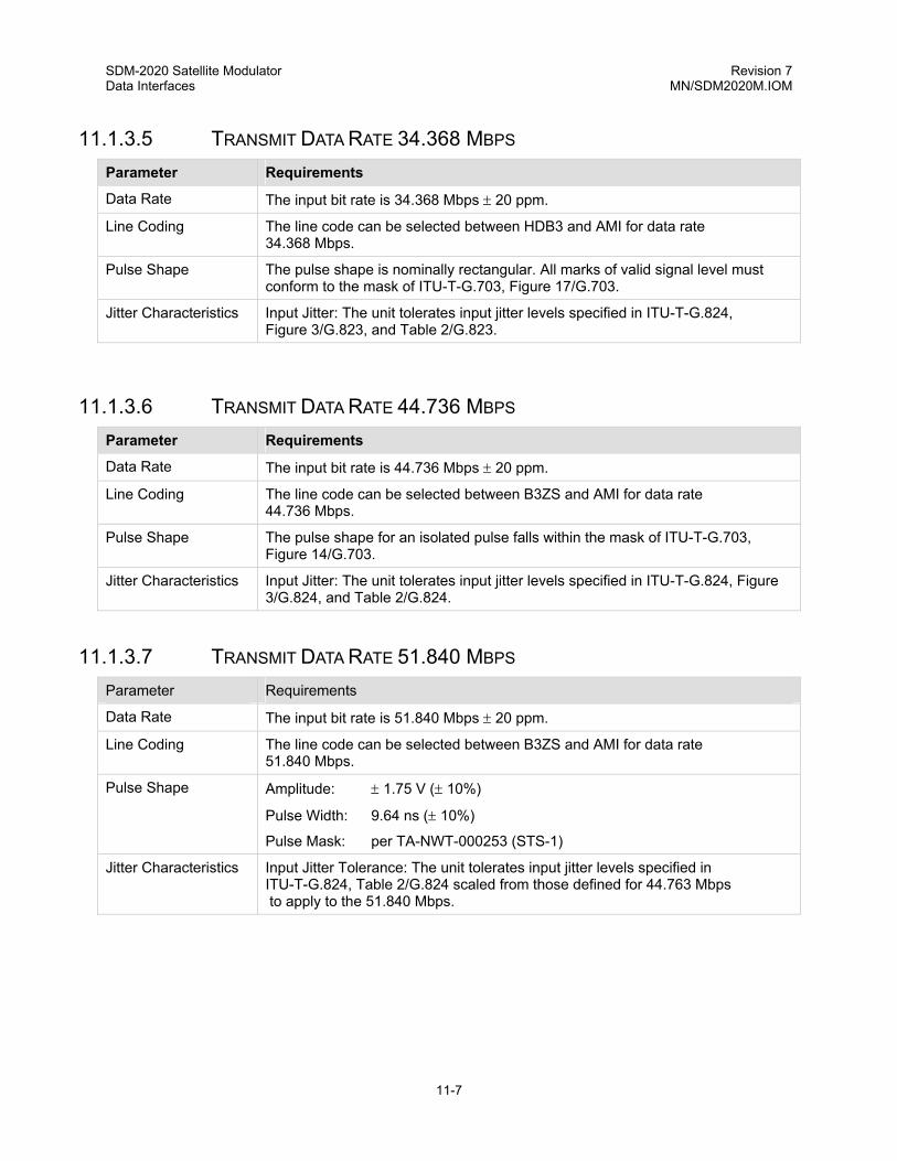
SDM-2020 Satellite Modulator Revision 7 Data Interfaces MN/SDM2020M.IOM
11-7
11.1.3.5 TRANSMIT DATA RATE 34.368 MBPS Parameter Requirements
Data Rate The input bit rate is 34.368 Mbps ± 20 ppm.
Line Coding The line code can be selected between HDB3 and AMI for data rate 34.368 Mbps.
Pulse Shape The pulse shape is nominally rectangular. All marks of valid signal level must conform to the mask of ITU-T-G.703, Figure 17/G.703.
Jitter Characteristics Input Jitter: The unit tolerates input jitter levels specified in ITU-T-G.824, Figure 3/G.823, and Table 2/G.823.
11.1.3.6 TRANSMIT DATA RATE 44.736 MBPS Parameter Requirements
Data Rate The input bit rate is 44.736 Mbps ± 20 ppm.
Line Coding The line code can be selected between B3ZS and AMI for data rate 44.736 Mbps.
Pulse Shape The pulse shape for an isolated pulse falls within the mask of ITU-T-G.703, Figure 14/G.703.
Jitter Characteristics Input Jitter: The unit tolerates input jitter levels specified in ITU-T-G.824, Figure 3/G.824, and Table 2/G.824.
11.1.3.7 TRANSMIT DATA RATE 51.840 MBPS Parameter Requirements
Data Rate The input bit rate is 51.840 Mbps ± 20 ppm.
Line Coding The line code can be selected between B3ZS and AMI for data rate 51.840 Mbps.
Pulse Shape Amplitude: ± 1.75 V (± 10%)
Pulse Width: 9.64 ns (± 10%)
Pulse Mask: per TA-NWT-000253 (STS-1)
Jitter Characteristics Input Jitter Tolerance: The unit tolerates input jitter levels specified in ITU-T-G.824, Table 2/G.824 scaled from those defined for 44.763 Mbps to apply to the 51.840 Mbps.

SDM-2020 Satellite Modulator Revision 7 Data Interfaces MN/SDM2020M.IOM
11-8
11.1.4 GENERAL TRANSMIT SPECIFICATIONS
11.1.4.1 TRANSMIT 2047 PATTERN GENERATION
The unit supplies a 2047 test pattern substitution into the TX data path when commanded by the host unit.
11.1.4.2 INPUT PORT RETURN LOSS Frequency Range
(kHz) Return Loss
(dB)
Data Rate/40 to Data Rate/20
Data Rate/20 to Data Rate
Data Rate to 1.5 x Data Rate
12
18
14
11.1.4.3 TRANSMIT SPECIFICATIONS Parameter Specification
AIS/Data Fault Detection The unit provides AIS/Data fault detection on the incoming TX data stream.
TX AIS Assertion The unit provides AIS substitution into the TX data path when commanded by the host unit.
RX Output Stable The unit provides data stable into the RX data path when installed in the modulator. Either RX data stable is removed when interface loop-back or interface loop through is turned ON.
Clock Activity Detection When installed in a modulator the unit provides activity detection for TX Terrestrial Clock. TX clock activity faults are communicated to the host unit and the fallback is SCT.
TX PLL Fault Detection The unit provides TX PLL fault detection. A fault is indicated upon the failure of either the G.703 clock recovery circuit or the TX clock dejitter circuit. When fault detection occurs the SCT is selected.
FPGA Program Error Detection/Reporting
The unit detects TX and RX FPGA programming errors and report errors to the host unit.

SDM-2020 Satellite Modulator Revision 7 Data Interfaces MN/SDM2020M.IOM
11-9
11.1.5 INTERFACE LOOP - THROUGH
The interface provides a “loop-through” mode of operation. The loop-through mode is intended to allow synchronization of RX data (RD) to Send Data (SD) when a demodulator/modulator are co-located. Loop-through mode is selectable only when the G.703 interface is installed in a modulator.
11.1.5.1 INTERFACE OPERATION WITHIN THE MODULATOR:
When loop-through mode is executed (turned ON) Send Data (SD), at the input to the interface, is routed to both the interface RX Data (RD) output and the host modulator data input. This mode of operation does not interfere with transmission of data over the satellite link. Transparent to the user, the following actions occur on the interface:
• Recovered clock and data from the Send Data (SD) input is looped to the interface receive data path.
• Interface receive data rate and line coding are set the same as TX.
• The RX Doppler/plesiochronous buffer is set for minimum depth and buffer reference clock is set to TX Terrestrial.
11.1.5.2 INTERFACE OPERATION WITHIN DEMODULATOR
Although loop-through mode is not selectable when the G.703 interface is installed in a demodulator, the following items must be considered when setting up the demodulator.
• Connect RX Data (RD) output of the co-located modulator to the Send Data (SD) of the co-located demodulator.
• Set the interface TX data rate and line coding the same as the co-located modulator.
• Set the G.703 interface buffer clock reference to TX Terrestrial.
ModulatorSD
RD
DemodulatorSD
RD
Tx IF
Rx IF
Figure 11-3. Co-Located Modulator and Demodulator

SDM-2020 Satellite Modulator Revision 7 Data Interfaces MN/SDM2020M.IOM
11-10
11.1.6 TEST MODES
11.1.6.1 INTERFACE LOOPBACK
The modulator/demodulator provides an “interface loopback” test mode of operation. When loopback mode is executed (turned ON), Send Data (SD) at the input to the interface is routed to both the interface RX Data (RD) output and the host modulator data input. Send Data (SD) is routed through as much of the interface circuitry as possible before being returned to the RX Data (RD) output. This mode of operation does not disrupt transmission of data over the satellite link when installed in a modulator.
• In a modulator application, the RX Data rate and line coding is automatically set to be compatible with the TX settings.
• In a demodulator application, TX data rate and line coding is automatically set to be compatible with RX settings and the buffer reference clock is set to TX terrestrial.
11.1.7 TERRESTRIAL INTERFACE TYPES
11.1.7.1 SEND DATA (SD), RECEIVE DATA (RD), AND EXTERNAL CLOCK CONNECTORS J3, J4, AND J6
The Send Data (SD) (J3), RX Data (RD) (J4), and EXT CLK (J6) connectors are all BNC type connectors and are terminated into 75Ω.
11.1.7.2 AUXILIARY FUNCTIONS CONNECTOR, J5
The connector is a 9-pin sub-miniature D female, with threaded jack nuts.
Modulator Fault (MF) and Demodulator Fault (DF) are single-ended open collector signals, where:
Voh=12V max. and Vol=0.5V max. @ Iol=8 ma.
A pull-up resistor external to the equipment is required.
For (MF) and (DF) a fault is indicated by an OFF (Vout = Hi) open collector transistor and the normal OK state is indicated by an ON transistor (Vout = Lo).
The Carrier Detect (CD) signal is a TTL output. When CD is high, it indicates the demodulator is locked.
TX IF ON/OFF: It is possible to use RTS signal on the auxiliary connector for turning the transmit carrier ON or OFF. The RS signal is enabled for this mode of operation and the polarity of the RS signal is programmed by the user.

SDM-2020 Satellite Modulator Revision 7 Data Interfaces MN/SDM2020M.IOM
11-11
Table 11-3. Auxiliary Connector, J5
Signal Function Name Pin # Type Comment
1 GND Signal Ground
Demodulator Fault Indicator
DF 2 O Demodulator Summary Fault
Redundancy switch application, TTL open collector output
Not Used N/A 3,5,8,9 N/A Wire to spare pad
RTS, TX OFF 4 I Modulator, TTL input
Modulator Fault Indicator MF 6 O Modulator Summary Fault
Redundancy switch application, TTL open collector output
Carrier Detect CD 7 O Demodulator, TTL output
11.1.8 MODULATOR INTERFACE
The physical interface to the modulator is a 96-pin DIN connector. The interface data transfer format is 187 byte (No Framing) Parallel Format.
11.1.9 POWER REQUIREMENTS
The G.703 interface requires +5 VDC (± 0.25V), +12 VDC (± 0.50V) and -12 VDC (± 0.50V) supplied from the base modulator. The power is supplied through the 96-pin (DIN) connector. During normal operation, the unit requires a maximum of 1A at +5 VDC, 100mA at +12V, and 50mA at -12V.
11.1.10 G.703 INTERFACE FRONT PANEL MENUS
The applicable menus are dependent on the G.703 interface application. Refer to Chapter 5.
11.1.11 G.703 REMOTE INTERFACE COMMANDS
The applicable remote commands are dependent on the G.703 interface application. Refer to Appendix A.

SDM-2020 Satellite Modulator Revision 7 Data Interfaces MN/SDM2020M.IOM
11-12
This page is intentionally left blank.

12-1
Chapter 12. SMPTE-310 DATA INTERFACE
12.1 GENERAL
This plug-in module provides the physical and electrical interface between external terrestrial data equipment and the modulator. The SMPTE-310 data interface is based on the DVB’s Synchronous Serial Interface (SSI) used with the SDM-2020 Modulator developed for video and high-speed data applications. The data is input/output on a BNC female connector as an 800-mV signal with biphase mark encoding. A separate auxiliary connector provides fault status.
12.1.1 APPLICABLE DOCUMENTS • Comtech EF Data SDM-2020 Modulator Specification, SP/5611
• SMPTE 310M Synchronous Serial Interface for MPEG-2 Digital Transport Stream
• TM 1449, Interfaces for CATV/SMATV Headends and Similar Professional Equipment
12.1.2 DESCRIPTION
The SMPTE-310 data interface is a plug-in module that inserts into the rear panel of the chassis. The data interface provides a physical and electrical connection between the external terrestrial circuit and the internal circuitry of the unit. By convention, a modem is Data Communications Equipment (DCE) where transmit data enters the data interface and receive data exits. The data interface has full-duplex capability but is automatically configured for simplex-transmit or simplex-receive operation, depending upon whether it is plugged into a modulator or demodulator chassis.
Figure 12-1 shows the SMPTE 310 data interface block diagram. At a functional level, the data interface has four I/O ports. Transmitted data by the modulator enters the SMPTE-310 data interface at the TX input as a synchronous serial bit stream, while data received by a demodulator is sent by the data interface at the RX outputs as a synchronous serial bit stream. The TX and RX serial data is biphase-mark encoded. The modem interface is byte-oriented interface with clock, data, and synchronous signals. Finally, the auxiliary function port provides status outputs for modulator and demodulator faults as well as input for control and transmission.

SDM-2020 Satellite Modulator Revision 7 Data Interfaces MN/SDM2020M.IOM
12-2
SMPTE 310Recovery
J6
Signal
Processing
Auxi
liary
MF
DF
/CD
J4
J3SMPTE 310Generator
Loopback LevelTranslators
M&C
Modulator /DemodulatorInterfaceTerrestrial
Interface
TxData75 OhmBNC-F
RxData75 OhmBNC-F
DCPower
J5
RTS
96 PinDIN
Figure 12-1. SMPTE-310M Interface Block Diagram

SDM-2020 Satellite Modulator Revision 7 Data Interfaces MN/SDM2020M.IOM
12-3
Figure 12-2 illustrates the SMPTE 310M module assembly.
.
J6
J5
J4J3
Figure 12-2. Module Assembly, Part NO. AS/6175-2.
12.1.3 SMPTE-310M DATA INTERFACE SPECIFICATIONS
Table 12-1. Specification Summary
Video Interface (Terrestrial)
Signal Type Biphase mark coded synchronous serial data per SMPTE-310M and TM 1449.
Connector Type 75Ω BNC.
Interface and Connector Impedance
Resistive 75Ω unbalanced, per SMPTE-310M.
TX and RX Signal Level
800 mV ± 10% per SPMTE-310M.
DC Offset 0.0 V ± 0.5 V.
Rise And Fall Times The rise and fall times, determined between the 20 and 80% amplitude points shall be within 0.4 ns and 5.0 ns and shall not differ by more than 1.6 ns, per SMPTE-310M.
Overshoot 10% maximum (on both rising and falling edges) per SPMTE-310M.
Receiver Sensitivity The receiver shall operate with up to 3 dB amplitude loss at 1/2 the interface clock.
Return Loss 30 dB minimum, 100 kHz to the interface clock frequency per SMPTE-310M.
ATSC Data Rate 8VSB: 19.392 658 46 Mbit/s = (4.5 E6) x (684/286) x (564/313)

SDM-2020 Satellite Modulator Revision 7 Data Interfaces MN/SDM2020M.IOM
12-4
Table 12-2. Specification Summary (Continued)
Video Interface (Terrestrial)
Clock Accuracy
Programmed data rate ± 100 ppm.
Clock Jitter, Drift And Wander
The interface clock frequency error (drift limit) shall not exceed ± 2.8 ppm.
The rate of frequency change (drift rate) shall not exceed 0.028 ppm/s.
The jitter in the timing of the interface signal transitions shall not exceed 2 ns p-p, measured over a bandwidth of 1 Hz to 1/100 of the interface clock frequency.
Cable Length, Typical
RG59 180 meters (591 feet)
Belden 8281 250 meters (820 feet)
Auxiliary Function Port
Signals DF (Demodulator Fault, open-collector output).
CD (Demodulator Carrier Detect, TTL output).
Connector 9 Pin D, female.
Monitor and Control
Monitored Functions
TX – PLL Lock (monitors presence of input data)
TX – State of RTS input on auxiliary function port
TX - FPGA load failure.
RX - FIFO Underflow/overflow.
RX - PLL lock.
RX - FPGA load failure.
Controlled Functions
Interface Loopback.
Interface Loop-through
General
Framing Formats
(to be provided by the demodulator, not this interface)
187 (no framing, pass-through mode).
188 (DVB/MPEG2 frame consisting of a sync. byte and 187 data bytes).
204 (frame consisting of sync. byte , 187 data bytes and 16 Reed-Solomon check bytes).
Environmental
Operating Temperature
Storage Temperature
Humidity
0 to + 50°C (32 to + 122°F)
-40 to + 70°C (-40 to +158°F)
Up to 95% non-condensing.

SDM-2020 Satellite Modulator Revision 7 Data Interfaces MN/SDM2020M.IOM
12-5
Table 12-3. Specification Summary (Continued)
Physical
Size SDM-2020 plug-in module compatible.
Hot Pluggable Not required. Unit power is turned off prior to removal or insertion of the data interface.
12.1.3.1 INTERFACE LOOPBACK MODE
In loopback mode, data entering the TX connector is returned after passing through the interface. The data entering the interface at the TX input is routed all the way through the TX path and out to the modulator at J1. All TX signals going to the modulator (TTL level before the TTL to LVDS translator) also are outed back to the RX path in place of the normal signals which would be coming from the demodulator.
• In a Modulator, TX data continues to enter the modulator and is TX during loopback.
• In a Demodulator, satellite data is not routed through the SMPTE-310M Data Interface.
12.1.3.2 INTERFACE LOOP-THROUGH MODE
In loop-through mode, operation is the same as in loopback mode, however, the test mode indications are not activated.
12.1.3.3 TX AND RX TERRESTRIAL DATA INTERFACE CONNECTOR (J3, J4, AND J6)
J3, J4 SMPTE-310M RX Data Outputs, BNC female. Both outputs are active simultaneously.
J6 SMPTE-310M TX Data Input, BNC female.
12.1.3.4 AUXILIARY FUNCTION PORT
The following paragraphs describe the electrical and physcial properties of the auxiliary function port.
12.1.3.4.1 Auxiliary Interface Electrical Specification
This port provides input/output of modem-specific signals.

SDM-2020 Satellite Modulator Revision 7 Data Interfaces MN/SDM2020M.IOM
12-6
Single ended open collector outputs (external pull-up resistor required) provide indicated Modulator Faults (MF) and Demodulator Faults (DF). For MF and DF, a fault is indicated by an OFF (Vout = Hi) open collector transistor and the normal OK state indicates an ON transistor (Vout = Lo). MF and DF are routed directly from the modulator or demodulator respectively. The characteristics of these outputs are:
Voh = 12V maximum
Vol = 0.5V maximum at Io1 = 8 mA
A carrier detect (CD) output signal provides an indication that the demodulator is locked. The output is TTL compatible. CD is routed directly from the demodulator. The default state of the CD is high when the unit is locked, but the sense will be programmable (function provided at the system level).
A Request to Send (RTS) input is provided to allow for remote control of the modulator transmission carrier. The ability to enable/disable control of the modulator via this signal, as well as the signal polarity, is programmed by the user (function provided at the system level).
12.1.3.4.2 Auxiliary Interface Connector –J5
This port provides input/output of the modem-specific signals. The connector is 9-pin subminiature D female, with threaded jack nuts.
Table 12-4. Auxiliary Interface Connector –J5
Signal Function Name Pin # Type Comment
1 GND Signal Ground
Demodualtor Fault Indicator
DF 2 O Demodulator Summary Fault. Open Collector
Redundancy switch appplication
3 N/C
Request to Send RTS 4 I Modulator Request to send. TX control. TTL
5 N/C
Modulator Fault Indication
MF 6 O Modulator Summary Fault. Open collector. Redundancy switch application.
Carrier Detect CD 7 O Demodulator. Carriewr detect. TTL
Legend: O = Output I = Input N/C = No Connection
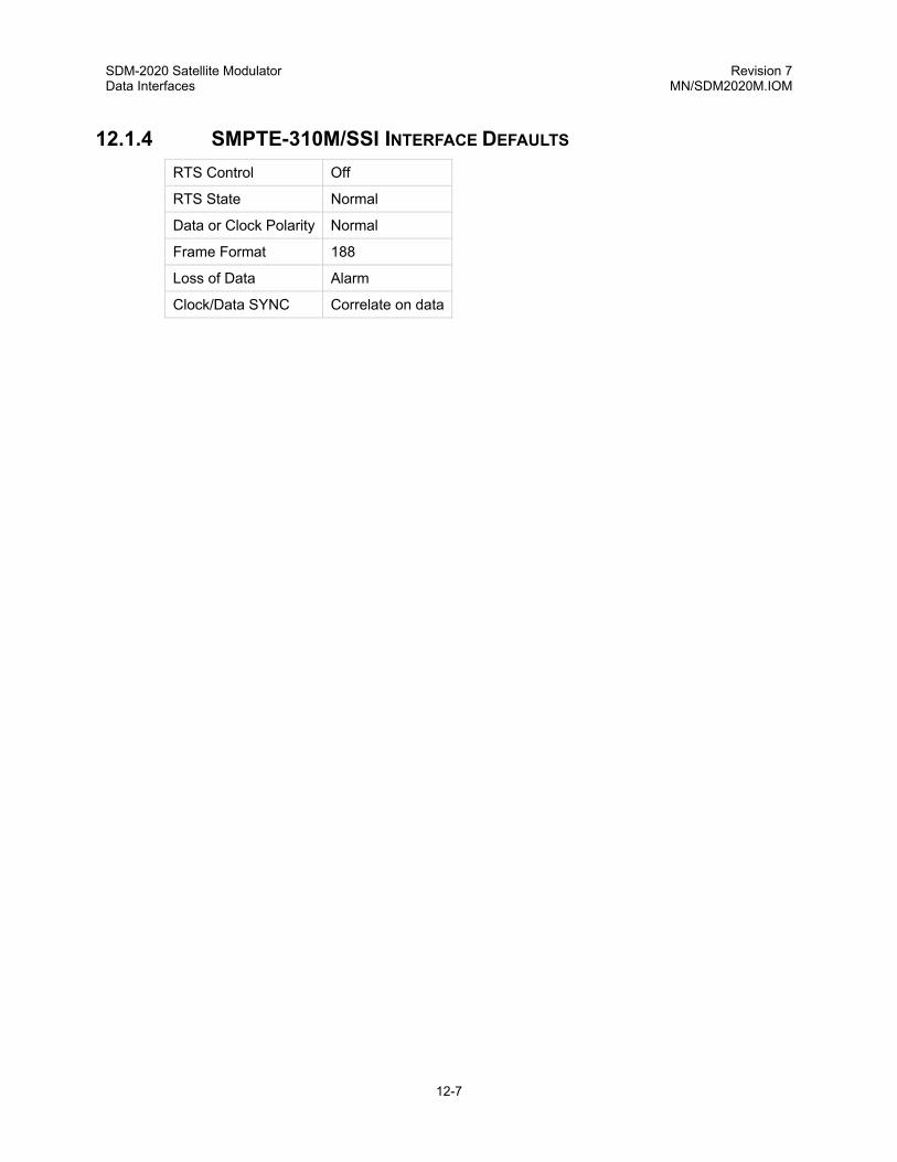
SDM-2020 Satellite Modulator Revision 7 Data Interfaces MN/SDM2020M.IOM
12-7
12.1.4 SMPTE-310M/SSI INTERFACE DEFAULTS RTS Control Off
RTS State Normal
Data or Clock Polarity Normal
Frame Format 188
Loss of Data Alarm
Clock/Data SYNC Correlate on data

SDM-2020 Satellite Modulator Revision 7 Data Interfaces MN/SDM2020M.IOM
12-8
12.1.5 SMPTE-310M/SSI INTERFACE FRONT PANEL MENUS
Refer to Chapter 5, Utility Interface menu.
12.1.6 SMPTE-310M/SSI REMOTE INTERFACE COMMANDS
Refer to Appendix A.

SDM-2020 Satellite Modulator Revision 7 Data Interfaces MN/SDM2020M.IOM
12-9
This page is intentionally left blank.

13-1
Chapter 13. ASI/LVDS DATA INTERFACE
13.1 ASI/LVDS INTERFACE
This plug-in module provides the physical and electrical interface between external terrestrial data equipment and the modulator. The ASI/LVDS implements the two most popular DVB data interfaces. The data is input/output on a BNC female connector as an 800 mV signal with biphase mark encoding. A separate auxiliary connector provides fault status.
13.1.1 APPLICABLE DOCUMENTS EN 50083-9, Interfaces for CATV/SMATV Headends and Similar Professional Equipment
13.1.2 DESCRIPTION
The ASI/LVDS data interface is a plug-in module that inserts into the rear panel of the chassis. The data interface provides a physical and electrical connection between the external terrestrial circuit and the internal circuitry of the unit. By convention, a modem is Data Communications Equipment (DCE) where transmit data enters the data interface and receive data exits. The data interface has full-duplex capability but is automatically configured for simplex-transmit or simplex-receive operation, depending upon whether it is plugged into a modulator or demodulator chassis.
Figure 13-1 shows the ASI/LVDS data interface block diagram. At a functional level, the data interface has three ASI I/O ports. One port is LVDS interface and an auxiliary connector. Transmitted data into the modulator enters the ASI/LVDS data interface at the TX input as a synchronous serial data stream, while data received by a demodulator is sent by the data interface at the RX outputs as a synchronous serial data stream. The ASI data stream is a serial, high-speed 8B/10 encoded signal, while the outputs for modulator and demodulator faults as well as input for control and transmission. Figure C-21 illustrates the ASI/LVDS module assembly.

SDM-2020 Satellite Modulator Revision 7 ASI/LVDS Data Interfaces MN/SDM2020M.IOM
13-2
ASIRecovery
J3-B
J4-A
LVD
S
Clk
D0-D7
DValid
Sync
J7 ASIGenerator
Loop
back
96Pi
nD
IN
M&CInterface
Modulator /DemodulatorInterfaceTerrestrial
Interface
TxASI
RxASI
BNC-F
BNC-F
DCPower
MF
DF
Tx On / Off
Ext Clk
Tx LVDS
Rx LVDS
Aux I / O
Tx ASI
Rx ASI
Recovery,ProcessingAnd ASI/ LVDSSelection
J6
J5
TxTe
rmin
atio
nJu
mpe
r
Leve
lTr
ansl
ator
s
Figure 13-1. ASI / LVDS Interface Block Diagram
Note: Manufacturer has discovered that PCBs were manufactured with J3-B and J4-A incorrectly identified. Connector J3 is ‘B’ and J4 is ‘A’. If any problem or concern is evident, do not hesitate to contact Comtech EF Data, Customer Support department.
13.1.3 ASI/LVDS INTERFACE SPECIFICATIONS
A 75Ω coaxial cable (Belden 8281 or equivalent) is recommended for all ASI connectors. Typical coaxial cable length is up to 70 meters (230 feet) with good quality coaxial cable. Typical attenuation of up to 8 dB at 270 MHz is permitted. The following cables, or an equivalent computer grade cable incorporating twisted, shielded pairs, are recommended for the LVDS interface:
• Belden type LV Computer M9768
• Belden 8175
The Belden 8175 has a lower capacitance, however it has a larger diameter and requires the selection of an appropriate connector shell. The typical cable length for the serial/parallel interfaces is ≤ 5 meters (16.405 feet).

SDM-2020 Satellite Modulator Revision 7 ASI/LVDS Data Interfaces MN/SDM2020M.IOM
13-3
Table 13-1. ASI/LVDS Specifications
General Specifications
Data Framing Formats 188, 204 byte packets per ETS 300 421, and None.
Hot Pluggable Not required. Unit power is turned off before removal or insertion of the data interface.
ASI Specifications
Data Rate 1.5 to 100 Mbit/s ASI.
Clock Rate Uncertainty Programmed data rate ± 100 ppm.
Transport Clock ASI The transport rate is 270 Mbit/s for all data rates.
Impedance 75Ω.
Return Loss 15 dB, frequencies, 5 to 270 MHz.
Loop Functions Loopback and Loop Thru
Connectors BNC female, 75Ω.
Electrical Properties Per EN 80053-9.
Packet Types Burst or distributed.
Signal Types Serial data.
Voltage Level 800 mV ± 10% into 75Ω.
ASI Data Loop 3 dB Frequency, TX Only
Wide: 2 Hz
Narrow: 0.3 Hz
Jitter Tolerance Meets ITU-T G.823 (3/93) and ITU-T G.824 (3/93)
Jitter Transfer ≤ 0.5 dB peaking up to cutoff frequency. -20 dB per decade beyond cutoff.
Cable Length, Typical 50 meters (165 feet), RG59
70 meters (230 feet), Belden 8281
Delay Variation Of Interface And Modulator
8 bits maximum, QPSK all data rates,
8PSK 2/3 and 5/6 all data rates. 8PSK 8/9 less than 80 Mbit/s
LVDS Specifications
Data Rate 1.5 to 100 Mbit/s, parallel LVDS
Clock Rate Uncertainty Programmed data rate + 100 ppm
Connectors 25-Pin D female per EN 80053-9.
Same connector is either TX or RX data (See Loopback / Loop Thru)
Electrical Properties per EN 80053-9
Signal Types D0 – D7, Sync, Dvalid and Clock per EN 80053-9
Data synchronization is detected by correlating the data stream for the MPEG2 sync pattern per ETS 300 421.

SDM-2020 Satellite Modulator Revision 7 ASI/LVDS Data Interfaces MN/SDM2020M.IOM
13-4
Table 13-1. ASI/LVDS Specifications (Continued)
Auxiliary Specifications
Fault Signal MF (modulator fault) and DF (demodulator fault). OC-TTL fault outputs.
TX ON / OFF TTL input, when enabled this signal turns the TX carrier ON / OFF.
Ext Clock Pin(s) reserved, but not defined
Monitor & Control
Interface Select ASI or LVDS
Auxiliary Functions Transmitter Control: TX IF Control ON / OFF
Polarity select Normal or Inverted
Controlled Functions
Interface Select: ASI or LVDS
Interface Loopback
Interface Loop Thru
Data Rate
TX ASI Data Input J3 / J4 Select
Loss of data. Programmable as Fault or Alarm
Clock, Normal or Inverted
Data, Normal or Inverted
Monitored Functions
Loss of TX Data (Data Connector Removed): The modulator indicates a loss of sync (framed modes) and transmits all 1s in the data portion of the frame.
The demodulator detects the presence of all ones and reports it to the display and remote port.
TX clock PLL program error
Data violations (TX)
FIFO Faults
ASI Data Loop BW Selection
Wide and Narrow
Additional M&C
Monitored Functions
Loss of TX Data or Clock (Data Connector Removed): The modulator indicates a loss of sync (frame and mode) and transmits all 1s in the data portion of the frame.
The demodulator detects the presence of all ones and reports it to the display and remote port.
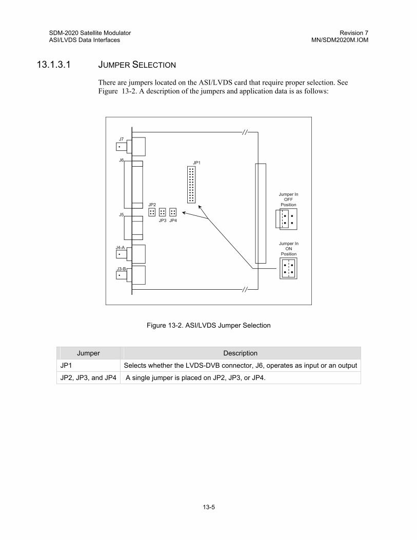
SDM-2020 Satellite Modulator Revision 7 ASI/LVDS Data Interfaces MN/SDM2020M.IOM
13-5
13.1.3.1 JUMPER SELECTION
There are jumpers located on the ASI/LVDS card that require proper selection. See Figure 13-2. A description of the jumpers and application data is as follows:
•
•
•
• • • • • • • • • • • • • • • • • • • • • • • • • •
• • • • • • • • • • • •
JP1
JP2
JP3 JP4
• • • •
Jumper InON
Position
J6
J7
J3-B
J4-A
J5 • • • •
Jumper InOFF
Position
Figure 13-2. ASI/LVDS Jumper Selection
Jumper Description
JP1 Selects whether the LVDS-DVB connector, J6, operates as input or an output
JP2, JP3, and JP4 A single jumper is placed on JP2, JP3, or JP4.

SDM-2020 Satellite Modulator Revision 7 ASI/LVDS Data Interfaces MN/SDM2020M.IOM
13-6
13.1.3.2 APPLICABLE JUMPER DATA
When the ASI portion of the interface is used JP1 is normally positioned Off so that the pins are not connected. Also, JP2 is normally set to On. This allows installation of the interface in either the modulator or demodulator without moving any jumpers. Refer to Table 13-2 for Modulator/Demodulator Jumper Selection.
Table 13-2. Modulator /Demodulator Jumper Selection
Modulator Jumper Selection
Jumper ON/OFF Description
JP1 ON Selects J6, the LVDS-DVB connector as an input.
JP1 OFF Normal Setting. Selects J6 as an output for Loopback or Loop Thru operation in conjunction with the ASI signals.
JP2 ON Normal Setting. Selects pins 2 and 15 of J6 as GND.
JP3 Not Used
For future use.
JP4 ON Selects pins 2 and 15 as REFCLKB and REFCLKA outputs from J6. This is used as a byte clock reference by other equipment.
JP4 OFF Normal Setting.
Demodulator Jumper Selection
Jumper ON/OFF Description
JP1 ON Selects J6 as an input for loopback operation.
JP1 OFF Normal Setting. Selects J6, LVDS-DVB connector, as an output for RX data. Also, it is used for loopback operation in conjunction with the ASI signals.
JP2 ON Normal Setting. Selects pins 2 and 15 of J6 as GND.
JP3 Not Used
For future use.
JP4 Not Used
Jumper belongs on J2.
13.1.4 LOOPBACK
In Loopback the TX input from the terrestrial circuit is routed through the interface to the terrestrial RX output. In a modulator chassis, TX data continues to enter the modulator and the TX IF is transmitted during Loopback.
In the demodulator, satellite data is interrupted during Loopback and the data entering the TX connector is returned to the RX connector. Demodulator data from the satellite is not routed to the modulator by the data interface. This is a test mode and illuminates the TEST LED.

SDM-2020 Satellite Modulator Revision 7 ASI/LVDS Data Interfaces MN/SDM2020M.IOM
13-7
13.1.4.1 LOOPBACK CONNECTION
Refer to Table 13-3 for additional requirements for Loopback.
Table 13-3. Loopback Connections
ASI Interface is active in Modulator
Loops ASI input, J3 (or J4), to ASI output, J7. If JP1 is Off, then J3 (J4) also loops to J6, the LVDS-DVB parallel output The LVDS signal contains D0-D7, Sync, Dvalid, and Clock
LVDS Interface is active in Modulator
If J1 is On, then J6 (LVDS-DVB input) is looped to the ASI output J7.
ASI Interface is active in Demodulator
JP1 is Off (Normal): When Loopback is engaged the TX ASI (J3) input connects simultaneously to the RX ASI (J7) and to the RX LVDS connector (J6). The LVDS signal contains D0-D7, Sync, Dvalid, and Clock JP1 is On: When Loopback is engaged the TX LVDS (J6) input connects to the RX ASI (J7) connector.
LVDS Interface is active (output) in Demodulator
JP1 is ON: When Loopback is engaged the TX LVDS (J6) input connects to the RX ASI connector (J7). The LVDS signal contains D0-D7, Sync, Dvalid, and Clock. JP1 is OFF (Normal): When Loopback is engaged the TX ASI input connects to the RX ASI connector and to the RX LVDS connector. The LVDS signal contains D0-D7, Sync, Dvalid, and Clock.
13.1.4.2 LOOP THROUGH
The operation of Loop Thru is the same as Loopback except the normal operating mode not a test mode, and the TEST LED does not illuminate.
13.1.5 ASI CONNECTOR PINOUT
J3, J4 Transmit Data Input, BNC female
J7 Receive Data Output, BNC female

SDM-2020 Satellite Modulator Revision 7 ASI/LVDS Data Interfaces MN/SDM2020M.IOM
13-8
13.1.6 LVDS CONNECTOR PINOUT (J6)
The LVDS connector is a 25-Pin D female type, with threaded jack nuts.
LVDS signal levels are as defined in EN50083-9. The differential sense of all signal pairs is a logic “1” when “A” is positive with respect to “B.” Some DBS applications require an inverted data or clock polarity and control of the signal polarity (normal or inverted) is provided. Input/Output (I/O) of the interface is determined by:
• Whether it is plugged into a modulator or demodulator
• Loopback or Loop Thru programming.
Signal Function/Name Pin # Type Comment Clock A 1 I / O Mod / Demod System Gnd / REFCLKB 2 O / Gnd Mod / Demod
Demod – GND only, no clock available Data 7 A(MSB/Serial) 3 I / O Mod / Demod Data 6 A 4 I / O Mod / Demod Data 5 A 5 I / O Mod / Demod Data 4 A 6 I / O Mod / Demod Data 3 A 7 I / O Mod / Demod Data 2 A 8 I / O Mod / Demod Data 1 A 9 I / O Mod / Demod Data 0 A 10 I / O Mod / Demod DVALID A 11 I / O Mod / Demod SYNC A 12 I / O Mod / Demod Cable Shield 13 I / O Mod / Demod Clock B 14 I / O Mod / Demod System Gnd / REFCLKA
15 O / Gnd Mod / Demod Demod – GND 0nly, no clock available
Data 7 B 16 I / O Mod / Demod Data 6 B 17 I / O Mod / Demod Data 5 B 18 I / O Mod / Demod Data 4 B 19 I / O Mod / Demod Data 3 B 20 I / O Mod / Demod Data 2 B 21 I / O Mod / Demod Data 1 B 22 I / O Mod / Demod Data 0 B 23 I / O Mod / Demod DVALID B 24 I / O Mod / Demod SYNC B 25 I / O Mod / Demod

SDM-2020 Satellite Modulator Revision 7 ASI/LVDS Data Interfaces MN/SDM2020M.IOM
13-9
13.1.7 AUXILIARY CONNECTOR PINOUT (J5)
The auxiliary connector is a 9-Pin D female connector.
Single-ended signals, such as the faults MF and DF, are open collector where:
Voh=12V max. and Vol=0.5V max. @ Iol=8 ma.
A pull-up resistor external to the equipment is required. A fault is indicated in the modulator or demodulator when the open collector is OFF. An ON collector indicates an OK status.
Ext Clk is an LVDS input.
Carrier Detect is a TTL output. TX IF ON / OFF is a single ended TTL input.
Refer to Table 13-4 for the 9-Pin D female connector.
Table 13-4. Auxiliary Connector Pinout (J5)
Signal Function Name Pin # Type Comment
1 GND Signal Ground
Demod Fault Indicator DF 2 O Demodulator Summary Fault
Redundancy switch application
SCT-A SCT-A 3 O LVDS Clock (A) From Modulator
TX IF ON / OFF TXOn-Off 4 I TTL
EXT Clk-B MC-B 5 I Demodulator, LVDS (TDB)
Mod Fault Indicator MF 6 O Modulator Summary Fault
Redundancy switch application
Carrier Detect CD 7 O Demodulator
SCT-B SCT-B 8 O LVDS Clock (B) From Modulator
EXT Clk-A MC-A 9 I Demodulator, LVDS (TBD)
Note: Ext Clk is not available.

SDM-2020 Satellite Modulator Revision 7 ASI/LVDS Data Interfaces MN/SDM2020M.IOM
13-10
13.1.8 ASI/LVDS INTERFACE DEFAULTS
Interface Select ASI
TX-IF Control Off
Data or Clock Normal
Frame Format 188
Loss of Data Alarm
Clock/Data Sync Correlate on data
Loopback / Loop Thru OFF
Loop Bandwidth Wide
ASI Link Select J3

14-1
Chapter 14. FULLY ACCESSIBLE SYSTEM TOPOLOGY
(FAST) OPTIONS
Comtech EF Data’s FAST system allows immediate implementation of different options through the user interface keypad. Some FAST options are available through the basic platform unit, while others require that the unit be equipped with optional hardware or that the hardware be installed in the field.
The options available through the FAST architecture include:
Option Minimum Software Version
16QAM-DVB 7.1.2 *
8PSK-DVB 5.3.1 *
OEM LCD 2.1.2
* Note: Units that shipped prior to July 1998 requirea factory-installed hardware upgrade to operate with 8PSK-DVB modulation.
14.1 FAST SYSTEM THEORY
FAST is an enhancement feature available only in Comtech EF Data products, enabling on-location upgrade of the operating feature set—in the rack—without removing a modulator from the setup. When service requirements change, the operator can upgrade the topology of the modulator to meet those requirements within minutes after confirmation by Comtech EF Data. This accelerated upgrade can be accomplished only because of FAST’s extensive use of programmable devices incorporating Comtech EF Data-proprietary signal processing techniques. These techniques allow the use of a unique access code to enable configuration of the available hardware. The access code can be purchased at any time from Comtech EF Data. Once obtained, the access code is loaded into the unit through the front panel keyboard or the rear remote port.
With the exclusive FAST technology, operators have maximum flexibility for enabling functions as they are required. FAST allows an operator to order a modulator precisely tailored for the initial application, reducing risk and cost overruns during the application integration process.

SDM-2020 Satellite Modulator Revision 7 FAST Options MN/SDM2020M.IOM
14-2
14.2 IMPLEMENTATION
FAST is factory-implemented in the modulator at the time of order. Hardware options for basic modulators can be ordered and installed either at the factory or in the field. The operator can select options that can be activated easily in the field, depending on the current hardware configuration of the modulator.
14.2.1 ACTIVATION PROCEDURE Obtain Modulator serial number as follows:
Press [CLEAR] to return to the Main menu.
Use [←] and [→] to select Function Select menu.
Press [ENTER].
Use [←] and [→] to select Utility Modulator Type menu.
Press [ENTER].
Use [←] and [→] to select Modulator Serial # menu.
Record serial number: ________________________
Select desired features as follows:
Use [←] and [→] to select MOD Options menu.
Press [ENTER].
Scroll [→] and select MOD Options.
Press [ENTER].
Scroll through the MOD Options and check off all features that display a “+” sign as follows:
16QAM [ ]
8PSK [ ]
OEM LCD [ ]
Notes:
If the menu displays a “0”, the unit will need to be returned to the manufacturer for the desired hardware upgrade.
If the unit displays an “X”, the unit can be upgraded in the field.
If the unit displays a “+”, the feature is installed.
If the unit displays a “-”, the feature is FAST accessible.
Press [CLEAR].
Contact Comtech EF Data Customer Support to order features.

SDM-2020 Satellite Modulator Revision 7 FAST Options MN/SDM2020M.IOM
14-3
Comtech EF Data Customer Support personnel will verify the order and provide an invoice and instructions.
Enter access codes as follows:
Press [CLEAR] to return to the Main menu.
Use [←] and [→] to select Function Select:Utility menu.
Press [ENTER].
Use [←] and [→] to select Utility:MOD Options menu.
Press [ENTER].
Use [←] and [→] to select Configuration Code-MOD menu
Press [ENTER].
Menu appears as follows: AAAAAAAAAA AAAAAAAAAA
Enter the access code. Observe the following:
1. To enter the code, press [ENTER] and use the [↑ ] [↓ ] keys to select an alpha numeric character.
2. Use [→ ] to move to the next character or to move to the next line. 3. Repeat the procedure until all the required characters of the code have been
entered. 4. After completing entry of the code, press [ENTER]. The unit should display
Modem Initialization and will reboot to the factory default settings with the new option available.
5. If a wrong or invalid code is entered, the unit will display Wrong Code Entered! and no changes will occur. Retry the code, verify that the code is correct, or request assistance from Comtech EF Data Customer Support department.

SDM-2020 Satellite Modulator Revision 7 FAST Options MN/SDM2020M.IOM
14-4
Entering Access Codes from the Remote Control Port, as follows:
1. Establish remote communication with the unit. Display will show REMOTE MODE (if applicable).
2. Enter the following commands as needed to enable the option related to each board:
Main Board <x/CCMD_code Overhead Board <x/CCOD_code MUX/DEMUX Board <x/CCMX_code TX Reed-Solomon <x/CCTR_code RX Reed Solomon <x/CCRR_code
X = address
Code =20 digit configuration code
3. The modem should re-initialize and boot up to the factory default setting.
Note: If the unit is an SDR-54/54A, the power should be cycled to re- initialize the unit and enable the option(s).
Verify the upgrade, as follows:
1. Press [CLEAR] to return to the Main menu.
2. Use [ ← ] and [ → ] to select Function Select:Utility menu.
3. Press [ENTER].
4. Use [ ← ] and [ → ] to select Utility:MOD Options menu.
5. Press [ENTER].
6. Use [ ← ] and [→ ] to scroll through the features. Visually check selected features for a “+” sign. If a “+” sign is evident, the upgrade is completed.
If upgrade is incorrect, the menu display will exhibit, “WRONG CODE ENTERED!.” Repeat procedures. If the error message remains, contact Comtech EF Data Customer Support personnel for further instructions.

A-1
Appendix A. REMOTE CONTROL OPERATION
This appendix describes the remote control operation of the SDM-2020 Modulator.
• Firmware number: FW/5613-1AG
FW/5613-2AG • Software version: 9.1.2
Remote controls and status information are transferred via an EIA-485 (optional EIA-232) serial communications link. Commands and data are transferred on the remote control communications link as US ASCII-encoded character strings. The remote communications link is operated in a half-duplex mode.
A remote controller or terminal initiates communications on the remote link. The modem never transmits data on the link unless it is commanded to do so.
Some commands and status information are interface-type dependent.
A.1 MESSAGE STRUCTURE
The ASCII character format used requires 11 bits/character:
• 1 start bit
• 1 parity bit (Not applicable to 8 information bit setup)
• 2 stop bits
• 7 information bits or 8 information bits
Messages on the remote link fall into the categories of commands and responses. Commands are messages, which are transmitted to a satellite modem, while responses are messages returned by a satellite modem in response to a command.
SDM-2020 Satellite Modulator Revision 7 Remote Control Operation MN/SDM2020M.IOM
A-2
The general message structure is as follows:
• Start Character • Device Address ‘add’
• Command/Response
• End of Message Character
If a command is issued remotely with the intent to change a modulator configurable parameter, the ‘REM_’ command must be issued first. This is to avoid data collision if one was to be changing data from the front panel while another was sending a remote command at the same time.
The first exception to the rule is if a command was issued to check a parameter status. The ‘REM_’ command would not be required first and a status would be returned normally.
The second exception to this rule is if the ‘MCP_’ command is issued for program configuration changes or a status request. When this particular command is issued with a command string attached, the Modulator will automatically engage remote mode, followed by the execution of the ‘MCP_’ command. While this command is being processed, any key presses from the front panel are stored in a keyboard buffer and executed after the MCP command is completed.
A.1.1 START CHARACTER
A single character precedes all messages transmitted on the remote link. This character flags the start of a message. This character is:
• “<” for commands
• “>” for responses
A.1.2 DEVICE ADDRESS
The device address is the address of the one satellite modulator which is designated to receive a transmitted command, or which is responding to a command.
Note: Address 0 is reserved as a global address which simultaneously addresses all devices on a given communications link.
Valid device addresses are 1 to 3 characters long, and in the range of 1 to 255. Devices do not acknowledge global commands.
Each satellite modulator, which is connected to a common remote communications link, must be assigned its own unique address. Addresses are software selectable at the modulator, and must be in the range of 1 to 255.

SDM-2020 Satellite Modulator Revision 7 Remote Control Operation MN/SDM2020M.IOM
A-3
A.1.3 COMMAND/RESPONSE
The command/response portion of the message contains a variable-length character sequence, which conveys command and response data.
If a satellite modulator receives a message addressed to it, which does not match the established protocol or cannot be implemented, a negative acknowledgment message is sent in response. These acknowledgment messages are:
>add/?ER1_PARITY ERROR'cr''lf']
(Error message for received parity errors.)
>add/?ER2_INVALID PARAMETER'cr''lf']
(Error message for a recognized command which cannot be implemented or has parameters which are out of range.)
>add/?ER3_UNRECOGNIZABLE COMMAND'cr''lf']
(Error message for unrecognizable command or bad
command syntax.)
>add/?ER4_MODEM IN LOCAL MODE'cr''lf']
(Modem in local error; send the REM command to go to
remote mode.)
>add/?ER5_HARD CODED PARAMETER'cr''lf']
(Error message indicating that the parameter is hardware
dependent and may not be changed remotely.)
Note: “add” is used to indicate a valid 1 to 3 character device address in the range between 1 and 255.

SDM-2020 Satellite Modulator Revision 7 Remote Control Operation MN/SDM2020M.IOM
A-4
A.1.4 END CHARACTER
A single character signals the end of each message:
• “cr” Carriage return character for commands
• “lf” Line feed
• “]” End bracket for responses

SDM-2020 Satellite Modulator Revision 7 Remote Control Operation MN/SDM2020M.IOM
A-5
A.2 CONFIGURATION COMMANDS/RESPONSES
A.2.1 MODULATOR CONFIGURATION COMMANDS
Parameter Type
Command/Status/ Response Description of Arguments Comments
Modulator Frequency
Command: Response: Status: Response:
<add/MF_nnn.nnnn'cr' >add/MF_nnn.nnnn'cr' RF_OFF'cr''lf'] <add/MF_'cr' >add/MF_nnn.nnnn'cr''lf']
Where: nnn.nnnn = Frequency in MHz, 50.0000 to 180.0000 in 2.5 kHz steps. Note: When the modulator frequency is programmed, the RF output is switched off.
RF Output (IF Output)
Command: Response: Status: Response:
<add/RF_xxx'cr' >add/RF_xxx'cr'lf'] <add/RF_'cr' >add/RF_xxx'cr''lf']
Where: xxx = ON or OFF.
Modulator Rate Assignment
Command: Response: Status: Response:
<add/AMRV_nnnnn_mmm.mmmmmm'cr' >add/AMRV_nnnnn_mmm.mmmmmm'cr''lf'] <add/AMRV_'cr' >add/AMRV_nnnnn_mmm.mmmmmm'cr''lf']
Where: nnnnn = 1/2 (QPSK 1/2) [Coder rate], 3/4 (QPSK 3/4), 7/8 (QPSK 7/8), 5/6 (QPSK 5/6), 2/3 (QPSK 2/3), 8P23 (8PSK 2/3), 8P56 (8PSK 5/6), 8P89 (8PSK 8/9), 16Q34 (16QAM 3/4), 16Q78 (16QAM 7/8). mmm.mmmmmm = Data rate in MHz. Note: When using a SMPTE 310M interface, the data rate is fixed at 19.392658 MHz. While the code rate can be changed as applicable, an invalid parameter message will be generated if any other data rate is input for change.

SDM-2020 Satellite Modulator Revision 7 Remote Control Operation MN/SDM2020M.IOM
A-6
Parameter Type
Command/Status/ Response Description of Arguments Comments
Symbol Rate Assignment
Command: Response: Status: Response:
<add/ASR_nnnnn_mm.mmmmmm'cr' >add/ASR_nnnnn_mm.mmmmmm'cr''lf'] <add/ASR_'cr' >add/ASR_nnnnn_mm.mmmmmm'cr''lf']
Where: nnnnn = 1/2 (QPSK 1/2) [Code rate], 3/4 (QPSK 3/4), 7/8 (QPSK 7/8), 5/6 (QPSK 5/6), 2/3 (QPSK 2/3), 8P23 (8PSK 2/3), 8P56 (8PSK 5/6), 8P89 (8PSK 8/9), 16Q34 (16QAM 3/4), 16Q78 (16QAM 7/8). mm.mmmmmm = Symbol rate in MHz. Note: When using a SMPTE 310M interface, the data rate is fixed at 19.392658 MHz. While the code rate can be changed as applicable, an invalid parameter message will be generated if any other data rate is input for change.
Set Modulator Output Power Level
Command: Response: Status: Response:
<add/MOP_snn.n'cr' >add/MOP_snn.n'cr''lf'] <add/MOP_'cr' >add/MOP_snn.n'cr''lf']
Where: snn.n = -20.0 to +5.0 in 0.1 steps (nominal range in dBm).
Scrambler Enable (Energy Dispersal)
Command: Response: Status: Response:
<add/SE_xxx'cr' >add/SE_xxx'cr''lf'] <add/SE_'cr' >add/SE_xxx'cr''lf']
Where: xxx = ON or OFF.
Modulator Spectrum Rotation
Command: Response: Status: Response:
<add/MSR_xxx'cr' >add/MSR_xxx'cr''lf'] <add/MSR_'cr' >add/MSR_xxx'cr''lf']
Where: xxx = NRM (normal spectrum) or INV (inverted spectrum).
Carrier Only Mode
Command: Response: Status: Response:
<add/COM_xxxxxx'cr' >add/COM_xxxxxx'cr''lf'] <add/COM_xxxxxx'cr' >add/COM_xxxxxx'cr''lf']
Where: xxxxxx = OFF, DUAL, OFFSET, or CENTER.
Transmit IF Output Power-up Condition
Command: Response: Status: Response:
<add/TXPU_xxxx'cr' >add/TXPU_xxxx'cr''lf'] <add/TXPU_xxxx'cr' >add/TXPU_xxxx'cr''lf']
Where: xxxx = LAST (last known state) or OFF (OFF). This command selects the state that the TX-IF Output will be at power up.
Set Modulator Power Offset
Command: Response: Status: Response:
<add/MPO_snn.n'cr' >add/MPO_snn.n'cr''lf'] <add/MPO_'cr' >add/MPO_snn.n'cr''lf']
Where: snn.n = +40.0 to -40.0 in 0.1 dB increments. Note: The modulator power offset is added to the nominal power level.

SDM-2020 Satellite Modulator Revision 7 Remote Control Operation MN/SDM2020M.IOM
A-7
Parameter Type
Command/Status/ Response Description of Arguments Comments
Modulator Type
Command: Response: Status: Response:
<add/MT_xxxx'cr' >add/MT_xxxx'cr'lf'] <add/MT_xxxx'cr' >add/MT_xxxx'cr'lf']
Where: xxxx = DVB1 or DVB2.
A.2.2 BULK MODULATOR CONFIGURATION
Parameter Type
Command/Status/
Response Description of Arguments Comments Bulk Modulator Config
Command: Response: Status: Response:
<add/BMC_p1,p2,p3,…..pn'cr' >add/BCM_p1,p2,p3, . . . pn'cr''lf'] <add/BMC_'cr' <add/BMC_p1,p2,p3,…..pn'cr''lf']
This command causes the modulator to be programmed with supplied parameters. All parameters are separated by a ',' except for the last parameter which has the standard command termination character ('cr'). Parameters that do not need to be changed can be nulled (no data between commas). Note: This is the only command that may be issued without first invoking the remote command ("<add/REM_"). The remote command is part of the initialization of this BMC_command. Status requests to not require that the remote command be issued at all. Where'pn' is the last parameter returned.

SDM-2020 Satellite Modulator Revision 7 Remote Control Operation MN/SDM2020M.IOM
A-8
BMC Parameters 1 to 33
Parameter Number 1 2 3 4 5 6 7 8 9 10 11 12 13 14 15 16 17 18 through 22 23 through 40
Parameter Name (Command Reference) Modulator Rate Assignment (ref."AMRV_"command) Modulator IF Frequency (ref. 'MF_' command). Modulator RF Output (ref. 'RF_' command). Modulator Output Power Level (ref. 'MOP_' command). Modulator Power Offset (ref. 'MPO_' command). Carrier Only Mode (ref. 'COM_' command). Modulator Spectrum Rotation (ref. 'MSR_' command). TX Output Power-up Configuration (ref. 'TXPU_' command). Modulator Type (ref. 'MT_' command). Scrambler Enable (ref. 'SE_' command). Transit Clock Phase (ref. 'TCP_' command). Transmit Data Phase (ref. 'TDP_' command). Transmit 2047 pattern generator (ref. 'ISP_' command). Transmit Sync Select (ref. 'SYNC_' command). Transit Data Fault Mode (ref. ‘ TDF_’command) Transmit Clock Activity Action (ref. 'TCAA_' command). DVB Framing Type (ref. 'TDVB_' command). Reserved Interface Specific
Description p1 = nnnnn-mmm.mmmmmm, code rate/date rate in Mbps p2 = nnn.nnnn, IF frequency in MHz p3 = n, where n is 0 or 1 (0 = Off, 1 = On). p4 = snn.n, transmitter output power level in dBm. p5 = snn.n, transmitter power offset level in dBm. p6 = n, where n is 0, 1, 2, 3 (0 = Off, 1 = Dual, 2 = Offset, 3 = Center) p7 = n, where n is 0 or 1 (0 = NRM, 1 =INV) p8 = n, where 'n' is '0' or ‘1’ (0 = Off, 1 = Last) p9 = n, where 'n' is '0' or ‘1’ (0 = DVB-1, 1 = DVB-2) p10 = n, where 'n' is ’0’ or ‘1’ (0 = Off , 1 = On) p11 = n, where 'n' = ‘0’ or ‘1’ (0 = NRM, 1 = INV) p12 = n, where 'n' = ‘0’ or ‘1’ (0 = NRM, 1 = INV) p13 = n, where ‘n’ is ‘0’ or ‘1’ (0 = Off, 1 = On) p14 = n, where ‘n’ is ‘0’, ‘1’, ‘2’ (0 = EXT, 1 = Data, 2 = Auto) p15 = n, where ‘n’ is ‘0’, ‘1’, ‘2’ (0 = None, 1 = Data Stable, 2 = AIS) p16 = n, where 'n' is '0' or ‘1’ (0 = Fault, 1 = Alarm) p17 = n, where n = '1' , ‘2’, ‘3’ (1 = 188, 2 = None, 3 = 204)

SDM-2020 Satellite Modulator Revision 7 Remote Control Operation MN/SDM2020M.IOM
A-9
A.2.2.1 RS-422 INTERFACE
Parameter Type
Command/Status/
Response Description of Arguments Comments BMC Parameters 23 to 40
23 24 25 26 27 28 29 thru 40
Interface Select Mode (ref. 'ISEL_' command). Interface Clock Mode (ref. ‘ICLK_' command). RTS TX-IF Control Mode (ref ‘RTSM_' command). RTS State Control (ref 'RTSS_' command). CTS State Control (ref ‘CTSS_' command). DM State Control (ref. ‘DM_’command). Reserved
p23 = n, where n = '0' (DVB, 1 =530) p24 = n, where n = '0' (Serial), '1' (Parallel). p25 = n, where n = '0' (Off), '1' (On). p26 = n, where n = '0' (Normal), '1' (Invert). p27 = n, where n = '0' (Normal), '1' (Invert). P28 = n, where n = ‘0’(Normal), ‘1’ (Invert)
A.2.2.2 LVDS INTERFACE
Parameter Type
Command/Status/
Response Description of Arguments Comments BMC Parameters 23 to 40
23 24 thru 40
Interface Clock Mode (ref. ‘ICLK_' command). Reserved
p23 = n, where n = '0' (Serial), '1' (Parallel).

SDM-2020 Satellite Modulator Revision 7 Remote Control Operation MN/SDM2020M.IOM
A-10
A.2.2.3 ASI/RS-422 INTERFACE
Parameter Type
Command/Status/
Response Description of Arguments Comments BCS Parameters 23 to 40
23 24 25 26 27 28 29 30 31 32 33 to 40
Interface Select Mode (ref. 'ISEL_' command). RTS TX-IF Control Mode (ref. 'RTSM_' command). RTS State Control (ref 'RTSS_' command). CTS State Control (ref 'CTSS_' command). DM State Control (ref 'DMS_' command). ST State Control (ref 'ST_' command). ASI Input Control (ref 'ASI_' command). ASI Loop Bandwith Control (ref ‘ASLB_’command). Interface Loopback (ref. ‘ILB_”command). Interface Loop Thru Control (ref. ‘ILM_”command). Reserved
p23 = n, where n = '0' (ASI), '1' (RS422). p24 = n, where n = '0' (Off), '1' (On). p25 = n, where n = '0' (Normal), '1' (Invert). p26 = n, where n = '0' (Normal), '1' (Invert). p27 = n, where n = '0' (Normal), '1' (Invert). p28 = n, where n = '0' (Normal), '1' (Invert). p29 = n, where n = 'A' (A-Input), 'B' (B-Input). p30 = n, where n = '0' (Wide), '1' (Narrow). p31 = n, where n = ‘0’ (Off), ‘1’ (On). p32 = n, where n = ‘0’ (Off), ‘1’ (On).

SDM-2020 Satellite Modulator Revision 7 Remote Control Operation MN/SDM2020M.IOM
A-11
A.2.2.4 ASI/LVDS INTERFACE
Parameter Type
Command/Status/
Response Description of Arguments Comments BCS Parameters 23 to 40
23 24 25 26 27 28 29 30 31 and 40
Interface Select Mode (ref. 'ISEL_' command). RTS TX-IF Control Mode (ref. 'RTSM_' command). RTS State Control (ref 'RTSS_' command). ASI Input Control (ref 'ASI_' command). ASI Loop Bandwidth Control (ref 'ASLB_' command). Interface Loopback (ref ‘ILB_’command). Interface Loop Thru Control (ref ‘ILM_’command) ASI Link Mode Control (ref ‘ASIA_’command) Reserved.
p23 = n, where n = '0' (ASI), '1' (LVDS). p24 = n, where n = '0' (Off), '1' (On). p25 = n, where n = '0' (Normal), '1' (Invert). p26 = n, where n = '0' (A-Input), '1' (B-Input). p27 = n, where n = '0' (Wide), '1' (Narrow). p28 = n, where n = '0' (Off), '1' (On). P29 = n, where n = '0' (Off), '1' (On). P30 = n, where n = ‘0’ (Manual), ‘1’ (Auto)
A.2.2.5 SMPTE-310 INTERFACE
Parameter Type
Command/Status/
Response Description of Arguments Comments BCS Parameters 23 to 40
23 24 25 26 27 to 40
RTS TX-IF Control Mode (ref ‘RTSM_’command) Interface Loopback (ref ‘RTSS_’command) Interface Loopback (ref: 'ILB_' command). RTS State Control (ref “ILM_”command) Reserved.
p23 = n, where n = ‘0’ (OFF) or ‘1’ (ON) p24 = n, where n = ‘0’ (Normal) or ‘1’ (Invert). p25 = n, where n = ‘0’ (OFF) or ‘1’ (ON). P26 = n where n = ‘0’ (OFF) or ‘1’ (ON)

SDM-2020 Satellite Modulator Revision 7 Remote Control Operation MN/SDM2020M.IOM
A-12
A.2.2.6 G.703 INTERFACE
Parameter Type
Command/Status/
Response Description of Arguments Comments BCS Parameters 23 to 40
23 24 25 26 27 28 to 40
TX Interface Coding Format (ref ‘ICFT_’command) RTS TX-IF Control Mode (ref ‘RTSM_’command) RTS State Control (ref: 'RTSS_' command). Interface Loopback (ref “ILB_”command) Interface Loop Thru Control (ref ‘ILM_’command) Reserved
p23 = n, where n = ‘0’ (AMI), ‘1’ (B3ZS), ‘2’ (HDB3), ‘3’ (B8ZS). p24 = n, where n = ‘0’ (Off) or ‘1’ (On). p25 = n, where n = ‘0’ (Normal) or ‘1’ (Invert). p26 = n where n = ‘0’ (OFF) or ‘1’ (ON). p27 = n where n = ‘0’ (OFF) or ‘1’ (ON).
A.2.2.7 ECL/HSSI INTERFACE
Parameter Type
Command/Status/
Response Description of Arguments Comments BCS Parameters 23 to 40
23 24 25 26 to 40
DTE TX-IF Control Mode (ref. 'DTEM_' command). DTE State Control (ref “DTES_”command). DCE State Control (ref “DCES_”command). Reserved.
p23 = n, where n = '0' (Off), '1' (On). P24 = n, where n ='0' (Normal), '1' (Invert). P25 = n, where n = '0' (zNormal), '1' (Invert).
A.2.3 BULK MODULATOR CONFIGURATION CHANGE STATUS
Parameter Type
Command/Status/ Response
Description of Arguments Comments
Bulk Modulator Config Change Status
Status: Response:
<add/BMCS_'cr' >add/BMCS_x'cr''lf']
The ‘x’ character is defined as follows: ‘@’ = No change since last BMC_ poll. ‘A’ = BMC_ response has changed since last BMC_ poll. This command indicates that a change has or has not occurred on the BMC_ response since the last BMC_poll.

SDM-2020 Satellite Modulator Revision 7 Remote Control Operation MN/SDM2020M.IOM
A-13
A.2.4 BULK MODULATOR CONFIGURATION ERRORS
Parameter Type
Command/ Status/
Response Description of Arguments Comments Bulk Modulator Config Errors
Command: Response:
<add/BMCE_'cr' >add/BCM_p1,p2,p3, . . . pn40'cr''lf']
When the BCME_command is executed, the host M&C will inspect all of the supplied parameters of the Bulk Modulator Command (BMC_) for failure. If any particular parameter or any combination of parameters is invalid or out of range, the resulting output error listing will allow the user to evaluate which parameters caused the error. The output error listing is a series of 40 characters, which are either a 1 or a 0, commas delimited. A listing of all 0 would indicate that there were no errors. A 1 in position 1 and position 17 might indicate that the symbol range of the modulator was exceeded (Data and Code Rate are programmed in position 1 and framing type which affects symbol rate would be position 17). This command is a status request only, and is cleared after another BMC_ command is issued. The BMCE_command will alaways report the status of all 40 parameters, whether these parameters are used or reserved. Note: Parameters 23 through 40 are interface dependent. Ensure to refer to the BMC_command for the particular type of interface that is installed in the modulator. Where'pn40' is the last parameter returned.

SDM-2020 Satellite Modulator Revision 7 Remote Control Operation MN/SDM2020M.IOM
A-14
A.2.5 INTERFACE CONFIGURATION COMMANDS
Parameter Type
Command/ Status/
Response Description of Arguments Comments Transmit Clock Phase
Command: Response: Status: Response:
<add/TCP_xxx'cr' >add/TCP_xxx'cr''lf'] <add/TCP_'cr' >add/TCP_xxx'cr''lf']
Where: xxx = NRM (normal clock phasing) or INV (inverted clock phasing).
Transmit Data Phase
Command: Response: Status: Response:
<add/TDP_xxx'cr' >add/TDP_xxx'cr''lf'] <add/TDP_'cr' >add/TDP_xxx'cr''lf']
Where: xxx = NRM (normal data phasing) or INV (inverted data phasing).
Interface Substitution Pattern
Command: Response: Status: Response:
<add/ISP_xxx'cr' >add/ISP_xxx'cr''lf'] <add/ISP_'cr' >add/ISP_xxx'cr''lf']
Where: xxx = On or Off. Note: Transmit 2047 Pattern.
DVB Sync Selection
Command: Response: Status: Response:
<add/SYNC_xxxx'cr' >add/SYNC_xxxx'cr''lf'] <add/SYNC_'cr' >add/SYNC_xxxx'cr''lf']
Where: xxxx = EXT (sync pulse), DATA (data sync byte), AUTO. Note: Data is only allowed with the ASI/LVDS interface operating in ASI mode.
Transmit Data Fault
Command: Response: Status: Response:
<add/TDF_xxxx'cr' >add/TDF_xxxx'cr''lf'] <add/TDF_'cr' >add/TDF_xxxx'cr''lf']
Where: xxxx = NONE, DATA, AIS.
DVB Framing Type
Command: Response: Status: Response:
<add/TDVB_xxxx'cr' >add/TDVB_xxxx'cr''lf'] <add/TDVB_'cr' >add/TDVB_xxxx'cr''lf']
Where: xxxx = 188, 204, NONE.
Interface Identification
Status: Response:
<add/INID_'cr' >add/INID_xxxxxxx'cr''lf']
Where: xxxxxxxxx = RS422, LVDS, ASI_RS422, ECL_TX, G.703, SMPTE 310M, ASI/LVDS, or UNKNOWN.
Interface Mode Config.
Command: Response: Status: Response:
<add/ICLK_xxx'cr' >add/ICLK_xxx'cr''lf'] <add/ICLK_'cr' >add/ICLK_xxx'cr''lf']
Where: xxx = SER (Serial mode, CLK = Data rate) or PAR (Parallel mode CLK = Data rate/8).

SDM-2020 Satellite Modulator Revision 7 Remote Control Operation MN/SDM2020M.IOM
A-15
Parameter Type
Command/ Status/
Response Description of Arguments Comments TX Clock Activity Action
Command: Response: Status: Response:
<add/TCAA_xxxxx'cr' >add/TCAA_xxxxx'cr''lf'] <add/TCAA_'cr' >add/TCAA_xxxxx'cr''lf']
Where: xxxxx = ALARM or FAULT.
A.2.6 SYSTEM CONFIGURATION COMMANDS
Parameter
Type Command/Status/
Response Description of Arguments Comments Time Of Day Command:
Response: Status: Response:
<add/TIME_hh:mmxx'cr' >add/TIME_hh:mmxx'cr''lf'] <add/TIME_'cr' >add/TIME_hh:mmxx'cr''lf']
Where: hh = 1 to 12 (hours). mm = 00 to 59 (minutes). xx = AM or PM.
Date Command: Response: Status: Response:
<add/DATE_mm/dd/yyyy'cr' >add/DATE_mm/dd/yyyy'cr''lf'] <add/DATE_'cr' >add/DATE_mm/dd/yyyy'cr''lf']
Where: mm = 1 to 12 (month). dd = 1 to 31 (day). yy = 00 to 99 (year) in 2-digit year mode. yyyy = 1975 to 1999, and 2000 to 2075 in 4-digit mode.
Remote Command: Response:
<add/REM_'cr' >add/REM_'cr''lf']
Configures the Modem for remote operation. The modulator will respond to any status request at any time. However, the modulator must be in 'Remote Mode' to change configuration parameters.
Clear Stored Faults
Command: Response:
<add/CLSF_'cr' >add/CLSF_'cr''lf']
This command is used to clear all stored faults logged by the modulator.
Save Mod Config.
Command: Response:
<add/SMC_nn'cr' >add/SMC_nn'cr''lf']
Where: n = 1, 2, 3, ..., 10 (stored configuration number). This command saves the current mod configuration for recall at a later time using the 'RMC_' command. Up to ten different mod configurations can be saved.
Recall Mod Config.
Command: Response:
<add/RMC_nn'cr' >add/RMC_nn'cr''lf']
Where: n = 1, 2, 3, ..., 10 (stored configuration number). This command causes the mod to be reprogrammed with configuration parameters previously saved using the 'SMC_' command. One of 10 saved configurations can be specified.

SDM-2020 Satellite Modulator Revision 7 Remote Control Operation MN/SDM2020M.IOM
A-16
Parameter Type
Command/Status/ Response Description of Arguments Comments
Alarm Relay State
Command: Response: Status: Response:
<add/ARLY_xxx'cr' >add/ARLY_xxx'cr''lf'] <add/ARLY_'cr' >add/ARLY_xxx'cr''lf']
Where: xxx = NRM (normal sense) or INV (inverted sense). This command controls the logic sense of the Mod alarm relay (NC and NO contacts).
A.3 STATUS COMMANDS/RESPONSES
A.3.1 CONFIGURATION STATUS
Parameter
Type Command/Status/
Response Description of Arguments Comments Modulator Rate
Command: Response:
<add/MR_'cr' >add/MR_nnnnn_mmm.mmmmmm'cr''lf']
Where: nnnnn = 1/2 (QPSK 1/2) [Coder rate], 3/4 (QPSK 3/4) 7/8 (QPSK 7/8), 5/6 (QPSK 5/6), 2/3 (QPSK 2/3), 8P23 (8PSK 2/3), 8P56 (8PSK 5/6), 8P89 (8PSK 8/9), 16Q34 (16QAM 3/4), 16Q78 (16QAM 7/8). mmm.mmmmmm = Data rate in MHz. Note: When using a SMPTE 310M interface, the data rate is fixed at 19.392658 MHz. While the code rate can be changed as applicable, an invalid parameter message will be generated if any other data rate is input for change.

SDM-2020 Satellite Modulator Revision 7 Remote Control Operation MN/SDM2020M.IOM
A-17
Parameter Type
Command/Status/ Response Description of Arguments Comments
Modulator Config. Status
Command: Response:
<add/MCS_'cr' >add/MCS_'cr' RF_xxx'cr' MF_nnn.nnnn'cr' MR_nnnn_mmm.mmmmmm'cr' AMRA_nnnn_mmm.mmmmmm'cr' AMRV_nnnn_mmm.mmmmmm'cr' MPO_snn.n'cr' MOP_snn.n'cr' SE_xxx'cr' COM_xxxxxx'cr' MSR_xxx'cr' MT_xxxx'cr' TXPU_xxxxx'cr''lf']
RF Output (ON/OFF) Modulator Frequency Modulator Rate Modulator Rate Modulator Rate Modulator Power Offset Modulator Output Power Scrambler Enable (ON/OFF) Carrier Only Mode Modulator Spectrum Rotation Modulator Type Transmit IF Output Power-up Configuration The Modulator configuration status command causes a block of data to be returned by the addressed mod. The block of data reflects the current configuration status of the modulator module. Additional configuration status of new options and features will always be appended to the end.
Modulator/ Coder Config. Program Status
Note: This command is used by Comtech EFData M:N protection switch to collect information that is necessary to configure back-up modulators. Because this command (content and/or order) can be changed at any time by Comtech EFData, it is advisable that other commands (“MCS_”, “ICS_”, or “BCS_”) be used for M&C systems. This command varies depending on the installed interface. The command is located in the interface sections.
Interface Config. Status
Note: The interface configuration status command causes a block of data to be returned by the addressed MODEM. The block reflects the current configuration of the interface. Additional configuration status of new options and features will always be appended to the end. This command varies depending on the installed interface. This command is located in the interface sections.
Modem Faults Status (Summary)
Command: Response:
<add/MFS_'cr' >add/MFS_'cr' MOD_xxx'cr' ITX_xxx'cr' CEQ_xxx'cr''lf']
Modulator (FLT/OK) Interface Transmit Side (FLT/OK) Common Equipment (FLT/OK)
Modulator Status
Command: Response:
<add/MS_'cr' >add/MS_'cr' RF_xxx'cr' MOD_xxx'cr' SYN_xxx'cr' DCS_xxx'cr' ICH_xxx'cr' QCH_xxx'cr' AGC_xxx'cr' IF_xxx'cr' CONF_xxx'cr' SFLT_xx'cr''lf']
RF Output (ON/OFF) Actual status not config. Module (OK/FLT) IF Synthesizer (OK/FLT) Data Clock Synthesizer (OK/FLT) I Channel (OK/FLT) Q Channel (OK/FLT) AGC Level (OK/FLT) IF Module Fault (OK/FLT) Configuration Fault (OK/FLT) Number of Stored Faults Logged (0 to 10)

SDM-2020 Satellite Modulator Revision 7 Remote Control Operation MN/SDM2020M.IOM
A-18
Parameter Type
Command/Status/ Response Description of Arguments Comments
Interface Status
Command: Response:
<add/ITXS_'cr' >add/ITXS_'cr' FSYN_xxx'cr' TXD_xxx'cr' PLL_xxx'cr' CLK_xxx'cr' FIFO_xxx'cr' INT_xxx'cr' DF_xxx'cr' VSYN_xxx'cr' SFLT_xx'cr''lf']
Frame Sync Lock (OK/FLT) Transmit Data (OK/FLT) Transmit Synthesizer PLL Lock (OK/FLT) Transmit Clock Activity (OK/FL) Transmit FIFO (OK/FLT) Interface Module (OK/FLT) Data Format (OK/FLT) Video Frame Sync (OK/FLT) Number of Stored Faults Logged (0 to 10)
A.4 COMMON EQUIPMENT STATUS
This common equipment status command causes a block of data to be returned which indicates the status of the common equipment .
Parameter Type Command/Status/
Response Description of
Arguments Comments Common Equipment Status
Command: Response:
<add/CES_’’ cr’ >add/CES_’cr’ M&C_xxx'cr' BAT_xxx'cr' +5_xxx'cr' +12_xxx'cr' -12_xxx'cr' MODE_xxxxxx'cr' SFLT_xx'cr'’If”]
Monitor & Control Module (OK/FLT) Battery/Clock (OK/FLT) +5 volt power supply (OK/FLT) +12 volt power supply (OK/FLT) -12 volt power supply (OK/FLT) Mode (LOCAL or REMMOTE) Number of stored faults logged (0 to 10)
A.5 STORED FAULTS STATUS
Information on stored faults is returned when requested. If no stored fault exists for a given fault number, the words “NO Fault” will be returned instead of the normal time/date status information. The following symbols are commonly used to define the stored faults status commands:
# Fault number (0 to 9). “0” is the first fault stored. hh Hours in 24-hr. format. mm Minutes. ss Seconds. MM Month. DD Day. YY or YYYY Year (2- or 4-digits)

SDM-2020 Satellite Modulator Revision 7 Remote Control Operation MN/SDM2020M.IOM
A-19
Parameter Type Command/Status/
Response Description of Arguments Comments Modulator Stored Faults Command:
Response: <add/MSF_#'cr' >add/MSF_# hh:mm:ss MM/DD/YYYY'cr' MOD_xxx'cr' SYN_xxx'cr' DCS_xxx'cr' ICH_xxx'cr' QCH_xxx'cr' AGC_xxx'cr' IF_xxx'cr' CONF_xxx'cr''lf']
Module (OK/FLT) IF Synthesizer (OK/FLT) Data Clock Synthesizer (OK/FLT) I Channel (OK/FLT) Q Channel (OK/FLT) AGC Level (OK/FLT) IF Module Fault (OK/FLT) Configuration (OK/FLT)
Interface Transmit Side Stored Faults
Command: Response:
<add/ITSF_#'cr' >add/ITSF_# hh:mm:ss MM/DD/YYYY'cr' FSYN_xxx'cr' TXD_xxx'cr' PLL_xxx'cr' CLK_xxx'cr' FIFO_xxx'cr' INT_xxx'cr' DF_xxx'cr''lf'] VSYN_xxx'cr''lf']
Frame Sync Lock (OK/FLT) Transmit Data (OK/FLT) Transmit Synthesizer PLL Lock (OK/FLT) Transmit Clock Activity (OK/FL) Transmit FIFO (OK/FLT) Interface Module (OK/FLT) Data Format (OK/FLT) Video Sync (OK/FLT)
Common Equipment Stored Faults
Command: Response:
<add/CSF_#'cr' >add/CSF_# hh:mm:ss MM/DD/YYYY'cr' M&C_xxx'cr' BAT_xxx'cr' +5_xxx'cr' +12_xxx'cr' -12_xxx'cr''lf']
Monitor & Control Module (OK/FLT) Battery/Clock (OK/FLT) +5V Power Supply (OK/FLT) +12V Power Supply (OK/FLT) -12V Power Supply (OK/FLT)

SDM-2020 Satellite Modulator Revision 7 Remote Control Operation MN/SDM2020M.IOM
A-20
A.5.1 BULK CONSOLIDATED STATUS
Parameter
Type Command/Status/
Response Description of Arguments Comments
Bulk Consol. Status
Command: Response:
<add/BCS_'cr' >add/BCS_p1,p2,p3, . . . pn'cr''lf']
This command causes bulk mod status to be returned. To reduce the length of the response, message parameter data are returned without identifiers. However, parameter identification can be determined by order of return. Each status parameter is terminated with a ',' (comma) except for the last parameter which has the standard message termination sequence ('cr''lf']). Most of the data returned is formatted the same way as the single command status request (refer to the appropriate portions of this document in preceding sections). Additional configuration status of new options and features will always be appended to the end.

SDM-2020 Satellite Modulator Revision 7 Remote Control Operation MN/SDM2020M.IOM
A-21
Parameter
Number Parameter Name
(Command Reference) Description BCS Parameters 1 to 33
1 2 3 4 5 6 7 8 9 10 11 12 13 14 15 16 17 18
Modem Remote/Local mode Modulator RF Output (ref. 'RF_' command). Modulator IF Frequency (ref. 'MF_' command). Modulator Rate (ref. 'MR_' command). Modulator Rate (ref. 'ASR_' command). Modulator Power Offset (ref. 'MPO_' command). Modulator Output Power Level (ref. 'MOP_' command). Scrambler Enable (ref. 'SE_' command). TX Output Power-up Configuration (ref. 'TXPU_' command). Carrier Only Mode (ref. 'COM_' command). Modulator Type (ref. 'MT_' command). Transmit Clock Phase (ref. 'TCP_' command). Transmit Data Phase (ref. 'TDP_' command). Transmit Data Phase (ref. 'TDF_' command). Transmit 2047 Pattern Generator (ref. 'ISP_' command). Transmit Clock Phase (ref. 'SYNC_' command). DVB Framing Type (ref. 'TDVB_' command). Modulator Spectrum Rotation (ref. 'MSR_' command).
p1 = n, where 'n' is '0' (LOCAL) or '1' (REMOTE). p2 = n, where 'n' is '0' (Off) or '1' (On). p3 = nnn.nnnn, IF frequency in MHz. p4 = nnnn_mmm.mmmmmm, code rate/data rate in Mbps. p5 = nnnn_mm.mmmmmm, code rate/symbol rate in Msps. p6 = snn.n, transmitter power offset level in dBm. p7 = snn.n, transmitter output power in dBm. p8 = n, where 'n' is '0' (off) or '1' (on). p9 = n, where 'n' is '0' (off) or '1' (last). p10 = n, where 'n' is '0' (Off), '1' (Dual),' 2' (Offset), or '3' (Center). p11 = n, where 'n' = '0' (DVB-1) or '1' (DVB-2). p12 = n, where 'n' is '0' (NRM), '1' (INV), or '2'. p13 = n, where 'n' is '0' (NRM) or '1' (INV). p14 = n, where 'n' is '0' (None), '1' (Data stable), or '2' (AIS). p15 = n, where 'n' is '0' (off) or '1' (on). p16 = n, where 'n' is '0' (EXT), '1' (DATA), or '2' (AUTO). p17 = n, where n = '1' (188), '2' (NONE), or '3' (204). p18 = n, where 'n' is '0' (NRM) or '1' (INV).

SDM-2020 Satellite Modulator Revision 7 Remote Control Operation MN/SDM2020M.IOM
A-22
Parameter
Number Parameter Name
(Command Reference) Description
19 and 20 21 22 23 to 32 33
Reserved. Interface ID (ref. 'INID_' command). Interface clock Mode (ref. 'ICLK_' command). Interface specific. TX Clock Activity Action (ref. 'TCAA' command).
p21 = 'xxxxxxx', where xxxxxxx = Interface type. p22 = n, where n = '0' (Serial) or '1' (Parallel). p33 = n, where n = '0' (Fault), '1' (Alarm).
A.5.2 BULK CONSOLIDATED STATUS FAULTS
Parameter Type
Command/ Status/
Response Description of Arguments Comments Bulk Consol. Status Faults
Command: Response:
<add/BCSF_'cr' >add/BCSF_abcdefghijklmnop'cr''lf']
This command causes all mod fault status to be returned. To reduce the length of the response, fault status is embedded into the bit structure of the characters that are returned. Faults are indicated by a binary 1 in the designated bit position. Additional fault status of new options and features will be appended to the end or use existing reserved bits. Character 'a': Modulator fault status character 1.
Bit 6 = 1 always. Bit 5 = Modulator module fault. Bit 4 = RF output status, actual not programmed status (1 = on, 0 = off). Bit 3 through Bit 0 = Binary representation (0 to 10) of the number of modulator stored faults.
Character 'b': Modulator fault status character 2.
Bit 6 = 1 always. Bit 5 = IF Synthesizer. Bit 4 = Data Clock Synthesizer. Bit 3 = I Channel. Bit 2 = Q Channel. Bit 1 = AGC Level. Bit 0 = Configuration.
Character 'c': Modulator fault status character 3.
Bit 6 = 1 always. Bit 5 = IF module. Bit 4 through Bit 0 reserved.

SDM-2020 Satellite Modulator Revision 7 Remote Control Operation MN/SDM2020M.IOM
A-23
Parameter Type
Command/ Status/
Response Description of Arguments Comments Character 'd': Interface transmit side faults character 1.
Bit 6 = 1 always. Bit 5 = Data Format Fault Bit 4 = reserved. Bit 3 through Bit 0 = Binary representation (0 to 10) of the number of interface transmit side stored faults.
Character 'e': Interface transmit side faults character 2.
Bit 6 = 1 always. Bit 5 = Frame Sync Lock. Bit 4 = Transmit Data Valid. Bit 3 = Transmit Clock Activity. Bit 2 = Transmit Synthesizer PLL Lock. Bit 1 = Transmit FIFO. Bit 0 = Interface module fault
Character 'f': Interface transmit side faults character 3.
Bit 6 = 1 always. Bit 5 through Bit 0 reserved.
Character 'g': Common equipment fault status character 1.
Bit 6 = 1 always. Bit 5 = reserved. Bit 4 through Bit 0 = Binary representation (0 to 10) of the number of common equipment stored faults.
Character 'h': Common equipment fault status character 2.
Bit 6 = 1 always. Bit 5 = Battery/Clock. Bit 4 = +5V power supply. Bit 3 = +12V power supply. Bit 2 = -12V power supply. Bit 1 = Monitor & Control Module. Bit 0 = reserved.

SDM-2020 Satellite Modulator Revision 7 Remote Control Operation MN/SDM2020M.IOM
A-24
A.5.3 CHANGE STATUS
Parameter Type
Command/ Status/
Response Description of
Arguments Comments Change Status
Command: Response:
<add/CS_'cr' >add/CS_x'cr''lf']
Where 'x' = '@' = NO change since last BCS_ and BCSF_ polls. 'A' = BCS_ response has changed since last BCS_ poll. 'B' = BCSF_ response has changed since last BCSF_ poll. 'C' = Both responses have changed since last BCS_ and BCSF_ polls. This command indicates that a change has or has not occurred on either the BCS_ or the BCSF_ response since the last BCS_ or BCSF_ poll.
A.5.4 UTILITY SYSTEM STATUS
Parameter Type
Command/ Status/
Response
Description of Arguments
Comments Equipment Type Command:
Response: <add/ET_'cr' >add/ET_tttttttt_xxx.yyy.zzz'cr''lf']
Where: tttttttt = Equipment type. xxx.yyy.zzz = Software version. This command returns the equipment type and the software version of the addressed device.
Monitor & Control Firmware Information
Command: Response:
<add/MCFI_'cr' >add/MCFI_'cr' VER_xxx.yyy.zzz'cr' FW/nnnnnn-ddrr'cr' mm/dd/yyyy'cr''lf']
Where: xxx.yyy.zzz = Software version number (0.0.0 to 999.999.999). nnnnnn = Firmware number (0 to 999999). dd = Firmware dash number (0 to 99). rr = Firmware revision (-, or A to ZZ).

SDM-2020 Satellite Modulator Revision 7 Remote Control Operation MN/SDM2020M.IOM
A-25
Parameter
Type
Command/ Status/
Response
Description of Arguments
Comments Boot Firmware Information
Command: Response:
<add/BFI_'cr' >add/BFI_'cr' Ver:_xxx_yyy.zzz'cr' FW/nnnnnn-ddrr’cr' mm/dd/yyyy'cr''lf']
Where: xxx.yyy.zzz = Software version number (0.0.0 to 999.999.999). nnnnnn = Firmware number (0 to 999999). dd = Firmware dash number (0 to 99). rr = Firmware revision (-, or A to ZZ).
Encoder Firmware Information (EFI)
Command: Response:
<add/EFI_'cr' >add/EFI_'cr' FW/nnnnn-ddrr'cr' Mm/dd/yyyy'cr''lf']
Where: nnnnn = Firmware number (0 to 65535). dd = Firmware dash number (0 to 99). rr = Firmware revision (-, or A to ZZ).
Reed-Solomon Firmware Information (RSFI)
Command: Response:
<add/RSFI_'cr' >add/RSFI_'cr' FW/nnnnn-ddrr'cr' Mm/dd/yyyy'cr''lf']
Where: nnnnn = Firmware number (0 to 65535). dd = Firmware dash number (0 to 99). rr = Firmware revision (-, or A to ZZ).
Interface Firmware Information (As Required)
Command: Response:
<add/IFI_'cr' >add/IFI_'cr' FW/nnnnn-ddrr'cr' mm/dd/yyyy'cr''lf']
Where: nnnnn = Firmware number (0 to 65535). dd= Firmware dash number (0 to 99). rr = Firmware revision (-, or A to ZZ).
Modem Options/ Misc. Information
Command: Response:
<add/MOI_'cr' >add/MOI_'cr' s,OEM_LCD'cr' s,16QAM'cr' s,8PSK'cr''lf']
Where: s = 0 (Not Installed, Not Upgradable) - = (Not Installed, FAST Upgradable) + = (Installed) (- or +) OEM LCD option (- or +) 16QAM Code Rate option (- or +) 8PSK Code Rate option
State of Product Command: Response:
<add/SOP_’cr’ >add/SOP_’cr’ Product address: abc’cr’ Baud format: abc’cr’ Baud rate: rrrrr bps’cr’ Comm type: <var-string1>’cr’ <varstring2>’cr’’lf’]
Where: a = Number of data bits (7) b = Parity type (O,E,N) c = Number of stop bits (1) rrrrr = baud rate (150, 300, 600, 1200, 2400, 4800, 9600, 14.4K, 19.2K) <var_string1> = Variable length strings explaining communication hardware type: RS-485, 2 wire RS-485, 4 wire RS-232 <var_string2> = Variable length strings explaining the intention of the product: “Under normal system operation” “REFLASH of BULK firmware required” “REFLASH of M&C firmware required”

SDM-2020 Satellite Modulator Revision 7 Remote Control Operation MN/SDM2020M.IOM
A-26
A.6 RS-422 INTERFACE COMMANDS
Parameter Type
Command/ Status/
Response Description
of Arguments Comments Interface Select Command
Command: Response: Status: Response:
<add/ISEL_xxxxxx'cr' >add/ISEL_xxxxxx'cr''lf'] <add/ISEL_'cr' >add/ISEL_xxxxxx'cr''lf']
This command is used for multiple interfaces: Where: Interface RS-422 xxxxxx = DVB or 530 Interface ASI/RS-422 xxxxxx = DVB or RS-422 Interfae ASI/LVDS xxxxxx = DVB or LVDS This command selects which interface connector will be used for data.
RTS TX-IF Control Mode
Command: Response: Status: Response:
<add/RTSM_xxx'cr' >add/RTSM_xxx'cr''lf'] <add/RTSM_'cr' >add/RTSM_xxx'cr''lf']
Where xxx = On or Off. This command configures the modem for the RTS TX-IF control mode. If ON is selected, the TX-IF output will only be turned On if the incoming RTS signal is asserted (also the TX-IF output has to be programmed ON and no major modulator faults are present). If OFF is selected, the TX-IF output will operate normal ignoring the RTS signal.
RTS State Control
Command: Response: Status: Response:
<add/RTSS_xxx'cr' >add/RTSS_xxx'cr''lf'] <add/RTSS_'cr' >add/RTSS_xxx'cr''lf']
Where xxx = NRM (Normal) or INV (Invert). This command controls the logic sense of the RTS signal.
CTS State Command: Response: Status: Response:
<add/CTSS_xxx'cr' >add/CTSS_xxx'cr''lf'] <add/CTSS_'cr' >add/CTSS_xxx'cr''lf']
Where xxx = NRM (Normal) or INV (Invert). This command control the logic sense of the CTS signal.
DM State Command: Response: Status: Response:
<add/DMS_xxx'cr' >add/DMS_xxx'cr''lf'] <add/DMS_'cr' >add/DMS_xxx'cr''lf']
Where xxx = NRM (Normal) or INV (Invert). This command controls the logic sense of the DM (DCS-ready) signal.

SDM-2020 Satellite Modulator Revision 7 Remote Control Operation MN/SDM2020M.IOM
A-27
Parameter Type
Command/ Status/
Response Description
of Arguments Comments MCP Command Config.
Command: Response:
<add/MCP_'cr' >add/MCP_'cr' ISEL_xxxxxx'cr' ICLK_xxx'cr' TDVB_xxxx'cr' MF_nnn.nnnn'cr' MR_nnnn_mmm.mmmmmm'cr' MPO_snn.n'cr' MOP_snn.n'cr' SE_xxx'cr' TCP_xxx'cr' TDP_xxxx'cr' TDF_xxxx'cr' ISP_xxx'cr' SYNC_xxxx'cr' MSR_xxx'cr' MT_xxxx'cr' TXPU_xxxxx'cr' COM_xxxxxx'cr' RTSM_xxx'cr' RTSS_xxx'cr' CTSS_xxx'cr' DMS_xxx'cr' TCAA_xxxx'cr' RF_xxx'cr''lf']
Interface Select Interface Mode DVB Framing Type Modulator Frequency Modulator Rate Modulator Power Offset Modulator Output Power Scrambler Enable (ON/OFF) Transmit Clock Phase Transmit Data Phase Transmit Data Fault Transmit 2047 Pattern Generator Transmit Sync Select Modulator Spectrum Rotation Modulator Type Transmit IF Output Power-up Configuration Carrier Only Mode RTS Mode Control RTS State Control CTS State Control DMS State Control TX Clock Activity Action RF Output (ON/OFF)
ICS Command Config.
Command: Response:
<add/ICS_'cr' >add/ICS_'cr' TCP_xxx'cr' TDP_xxxx'cr' ISP_xxx'cr' SYNC_xxxx'cr' TDF_xxxx'cr' TDVB_xxxx'cr' INID_xxxxxxxxx'cr' ISEL_xxxxxx'cr' ICLK_xxx'cr' RTSM_xxx'cr' RTSS_xxx'cr' CTSS_xxx'cr' DMS_xxx'cr' TCAA_xxxxx'cr''lf']
Transmit Clock Phase Transmit Data Phase Transmit 2047 Pattern Generator Transmit Sync Select Transmit Data Fault DVB Framing Type Interface Identification Interface Select Interface Mode RTS Mode Control RTS State Control CTS State Control DM State Control TX Clock Activity Action
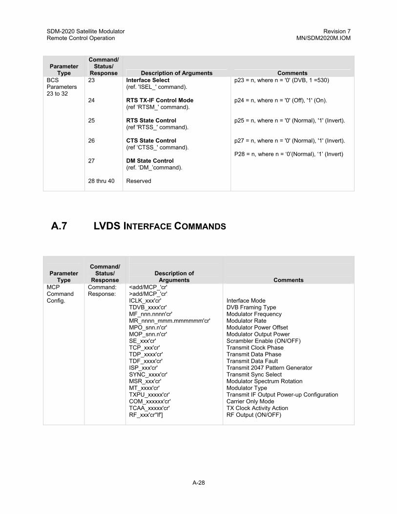
SDM-2020 Satellite Modulator Revision 7 Remote Control Operation MN/SDM2020M.IOM
A-28
Parameter Type
Command/Status/
Response Description of Arguments Comments BCS Parameters 23 to 32
23 24 25 26 27 28 thru 40
Interface Select (ref. 'ISEL_' command). RTS TX-IF Control Mode (ref ‘RTSM_' command). RTS State Control (ref 'RTSS_' command). CTS State Control (ref ‘CTSS_' command). DM State Control (ref. ‘DM_’command). Reserved
p23 = n, where n = '0' (DVB, 1 =530) p24 = n, where n = '0' (Off), '1' (On). p25 = n, where n = '0' (Normal), '1' (Invert). p27 = n, where n = '0' (Normal), '1' (Invert). P28 = n, where n = ‘0’(Normal), ‘1’ (Invert)
A.7 LVDS INTERFACE COMMANDS
Parameter
Type
Command/ Status/
Response
Description of Arguments
Comments MCP Command Config.
Command: Response:
<add/MCP_'cr' >add/MCP_'cr' ICLK_xxx'cr' TDVB_xxxx'cr' MF_nnn.nnnn'cr' MR_nnnn_mmm.mmmmmm'cr' MPO_snn.n'cr' MOP_snn.n'cr' SE_xxx'cr' TCP_xxx'cr' TDP_xxxx'cr' TDF_xxxx'cr' ISP_xxx'cr' SYNC_xxxx'cr' MSR_xxx'cr' MT_xxxx'cr' TXPU_xxxxx'cr' COM_xxxxxx'cr' TCAA_xxxxx'cr' RF_xxx'cr''lf']
Interface Mode DVB Framing Type Modulator Frequency Modulator Rate Modulator Power Offset Modulator Output Power Scrambler Enable (ON/OFF) Transmit Clock Phase Transmit Data Phase Transmit Data Fault Transmit 2047 Pattern Generator Transmit Sync Select Modulator Spectrum Rotation Modulator Type Transmit IF Output Power-up Configuration Carrier Only Mode TX Clock Activity Action RF Output (ON/OFF)

SDM-2020 Satellite Modulator Revision 7 Remote Control Operation MN/SDM2020M.IOM
A-29
Parameter
Type
Command/ Status/
Response
Description of Arguments
Comments ICS Command Config.
Command: Response:
<add/ICS_'cr' >add/ICS_'cr' TCP_xxx'cr' TDP_xxxx'cr' ISP_xxx'cr' SYNC_xxxx'cr' TDF_xxxx'cr' TDVB_xxxx'cr' INID_xxxxxxxxx'cr' ICLK_xxx'cr' TCAA_xxxxx'cr''lf']
Transmit Clock Phase Transmit Data Phase Transmit 2047 Pattern Generator Transmit Sync Select Transmit Data Fault DVB Framing Type Interface Identification Interface Mode TX Clock Activity Action
BCS Parameters 23 to 32
23 thru 32
Reserved.
A.8 ASI/RS-422 INTERFACE COMMANDS
Parameter Type
Command/ Status/
Response Description of Arguments Comments Interface Select Command
Command: Response: Status: Response:
<add/ISEL_xxxxx'cr' >add/ISEL_xxxxx'cr''lf'] <add/ISEL_'cr' >add/ISEL_xxxxx'cr''lf']
Where: xxxxx = ASI or RS422. This command selects which interface connector will be used for data.
ASI Link (Input) Select Command
Command: Response: Status: Response:
<add/ASI_x'cr' >add/ASI_x'cr''lf'] <add/ASI_'cr' >add/ASI_x'cr''lf']
Where: x = 'A' (For A-Input) or 'B' (For B-Input).
ASI Loop Bandwith Select Command
Command: Response: Status: Response:
<add/ASLB_xxxxxx'cr' >add/ASI_xxxxxx'cr''lf'] <add/ASLB_'cr' >add/ASI_xxxxxx'cr''lf']
Where xxxxxx = WIDE or NARROW
RTS TX-IF Control Mode
Command: Response: Status: Response:
<add/RTSM_xxx'cr' >add/RTSM_xxx'cr''lf'] <add/RTSM_'cr' >add/RTSM_xxx'cr''lf']
Where: xxx = ON or OFF. This command configures the modem for the RTS TX-IF control mode. If 'ON' is selected, the TX-IF output will only be turned on if the incoming RTS signal is asserted (also the TX-IF output has to be programmed ON and no major modulator faults are present). If 'OFF' is selected, the TX-IF output will operate normal ignoring the RTS signal.

SDM-2020 Satellite Modulator Revision 7 Remote Control Operation MN/SDM2020M.IOM
A-30
Parameter
Type
Command/ Status/
Response Description of Arguments Comments RTS State Control
Command: Response: Status: Response:
<add/RTSS_xxx'cr' >add/RTSS_xxx'cr''lf'] <add/RTSS_'cr' >add/RTSS_xxx'cr''lf']
Where: xxx = NRM (normal sense) or INV (inverted sense). This command controls the logic sense of the RTS signal.
CTS State Control
Command: Response: Status: Response:
<add/CTSS_xxx'cr' >add/CTSS_xxx'cr''lf'] <add/CTSS_'cr' >add/CTSS_xxx'cr''lf']
Where: xxx = NRM (normal sense) or INV (inverted sense). This command controls the logic sense of the CTS signal.
DM State Control
Command: Response: Status: Response:
<add/DMS_xxx'cr' >add/DMS_xxx'cr''lf'] <add/DMS_'cr' >add/DMS_xxx'cr''lf']
Where: xxx = NRM (normal sense) or INV (inverted sense). This command controls the logic sense of the DM (DCE-ready) signal.
ST State Control
Command: Response: Status: Response:
<add/ST_xxx'cr' >add/ST_xxx'cr''lf'] <add/ST_'cr' >add/ST_xxx'cr''lf']
Where: xxx = NRM (normal sense) or INV (inverted sense). This command controls the logic sense of the ST signal.
Interface Firmware Information
Command: Response:
<add/IFI_'cr' >add/IFI_'cr' FW/nnnnn-drr'cr' Mm/dd/yyyy'cr''If']
Where: nnnnn = Firmware number (0 to 65535). d = Firmware dash number (0 to 99). rr = Firmware revision (-, or A through ZZ).

SDM-2020 Satellite Modulator Revision 7 Remote Control Operation MN/SDM2020M.IOM
A-31
Parameter
Type
Command/ Status/
Response Description of Arguments Comments MCP Command Config.
Command: Response:
<add/MCP_'cr' >add/MCP_'cr' ISEL_xxxxxx'cr' ICLK_xxx'cr' TDVB_xxxx'cr' MF_nnn.nnnn'cr' MR_nnnn_mmm.mmmmmm'cr' MPO_snn.n'cr' MOP_snn.n'cr' SE_xxx'cr' TCP_xxx'cr' TDP_xxxx'cr' TDF_xxxx'cr' ISP_xxx'cr' SYNC_xxxx'cr' MSR_xxx'cr' MT_xxxx'cr' TXPU_xxxxx'cr' COM_xxxxxx'cr' ASI_x'cr' RTSM_xxxx'cr' RTSS_xxxx'cr' CTSS_xxxx'cr' DMS_xxxx'cr' ST_xxxx'cr' TCAA_xxxxx'cr' RF_xxx'cr' ASLB_xxxxxx’cr’’lf’]
Interface Select Interface Mode DVB Framing Type Modulator Frequency Modulator Rate Modulator Power Offset Modulator Output Power Scrambler Enable (ON/OFF) Transmit Clock Phase Transmit Data Phase Transmit Data Fault Transmit 2047 Pattern Generator Transmit Sync Select Modulator Spectrum Rotation Modulator Type Transmit IF Output Power-up Configuration Carrier Only Mode ASI Input RTS Mode Control RTS State Control CTS State Control DM State Control ST State Control TX Clock Activity Action RF Output (ON/OFF) ASI Loop BW (Wide/Narrow)
ICS Command Config.
Command: Response:
<add/ICS_'cr' >add/ICS_'cr' TCP_xxx'cr' TDP_xxxx'cr' ISP_xxx'cr' SYNC_xxxx'cr' TDF_xxxx'cr' TDVB_xxxx'cr' INID_xxxxxxxxx'cr' ISEL_xxxxxx'cr' ICLK_xxx'cr' ASI_x'cr' RTSM_xxx'cr' RTSS_xxx'cr' CTSS_xxx'cr' DMS_xxx'cr' ST_xxx'cr' TCAA_xxxxx'cr’ ASLB_xxxxxx’cr’’lf’]
Transmit Clock Phase Transmit Data Phase Transmit 2047 Pattern Generator Transmit Sync Select Transmit Data Fault DVB Framing Type Interface Identification Interface Select Interface Mode ASI Input RTS Mode Control RTS State Control CTS State Control DM State Control ST State Control TX Clock Activity Action ASI Loop Bandwidth

SDM-2020 Satellite Modulator Revision 7 Remote Control Operation MN/SDM2020M.IOM
A-32
Parameter
Number Parameter Name
(Command Reference)
Description BCS Parameters 23 to 32
23 24 25 26 27 28 29 30 31-32
Interface Select (ref. 'ISEL_' command). RTS TX-IF Control Mode (ref. 'RTSM_' command). RTS State Control (ref 'RTSS_' command). CTS State Control (ref 'CTSS_' command). DM State Control (ref 'DMS_' command). ST State Control (ref 'ST_' command). ASI Input Control (ref 'ASI_' command). ASI Loop Bandwith Control (ref ‘ASLB_’command) Reserved
p23 = n, where n = '0' (ASI), '1' (RS422). p24 = n, where n = '0' (Off), '1' (On). p25 = n, where n = '0' (Normal), '1' (Invert). p26 = n, where n = '0' (Normal), '1' (Invert). p27 = n, where n = '0' (Normal), '1' (Invert). p28 = n, where n = '0' (Normal), '1' (Invert). p29 = n, where n = 'A' (A-Input), 'B' (B-Input). p30 = n, where n = '0' (Wide), '1' (Narrow).
A.9 ECL/HSSI TX INTERFACE COMMANDS
Parameter Type
Command/ Status/
Response
Description of Arguments
Comments DTE TX-IF Control Mode
Command: Response: Status: Response:
<add/DTEM_xxx'cr' >add/DTEM_xxx'cr''lf'] <add/DTEM_'cr' >add/DTEM_xxx'cr''lf']
Where: xxx = ON or OFF. This command configures the modem for the DTE TX-IF control mode. If 'ON' is selected, the TX-IF output will only be turned on if the incoming DTE signal is asserted (also the TX-IF output has to be programmed ON and no major modulator faults are present). If 'OFF' is selected, the TX-IF output will operate normal ignoring the DTE signal.
DTE Status Command
Status: Response:
<add/EDTE_'cr' >add/EDTE_xxx'cr''lf']
Where: xxx = AVA (available) or UNA (unavailable).
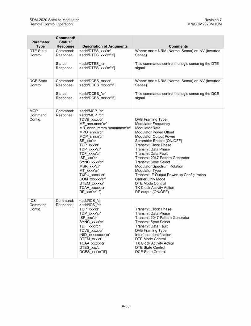
SDM-2020 Satellite Modulator Revision 7 Remote Control Operation MN/SDM2020M.IOM
A-33
Parameter
Type
Command/ Status/
Response
Description of Arguments
Comments DTE State Control
Command: Response: Status: Response:
<add/DTES_xxx'cr' >add/DTES_xxx'cr''lf'] <add/DTES_'cr' >add/DTES_xxx'cr''lf']
Where: xxx = NRM (Normal Sense) or INV (Inverted Sense) This commands control the logic sense og the DTE signal.
DCE State Control
Command: Response: Status: Response:
<add/DCES_xxx'cr' >add/DCES_xxx'cr''lf'] <add/DCES_'cr' >add/DCES_xxx'cr''lf']
Where: xxx = NRM (Normal Sense) or INV (Inverted Sense) This commands control the logic sense og the DCE signal.
MCP Command Config.
Command: Response:
<add/MCP_'cr' >add/MCP_'cr' TDVB_xxxx'cr' MF_nnn.nnnn'cr' MR_nnnn_mmm.mmmmmm'cr' MPO_snn.n'cr' MOP_snn.n'cr' SE_xxx'cr' TCP_xxx'cr' TDP_xxxx'cr' TDF_xxxx'cr' ISP_xxx'cr' SYNC_xxxx'cr' MSR_xxx'cr' MT_xxxx'cr' TXPU_xxxxx'cr' COM_xxxxxx'cr' DTEM_xxxx’cr’ TCAA_xxxxx’cr’ RF_xxx’cr’’If’]
DVB Framing Type Modulator Frequency Modulator Rate Modulator Power Offset Modulator Output Power Scrambler Enable (ON/OFF) Transmit Clock Phase Transmit Data Phase Transmit Data Fault Transmit 2047 Pattern Generator Transmit Sync Select Modulator Spectrum Rotation Modulator Type Transmit IF Output Power-up Configuration Carrier Only Mode DTE Mode Control TX Clock Activity Action RF output (ON/OFF)
ICS Command Config.
Command: Response:
<add/ICS_'cr' >add/ICS_'cr' TCP_xxx'cr' TDP_xxxx'cr' ISP_xxx'cr' SYNC_xxxx'cr' TDF_xxxx'cr' TDVB_xxxx'cr' INID_xxxxxxxxx'cr' DTEM_xxx’cr’ TCAA_xxxxx’cr’ DTES_xxx’cr’ DCES_xxx’cr’’If’]
Transmit Clock Phase Transmit Data Phase Transmit 2047 Pattern Generator Transmit Sync Select Transmit Data Fault DVB Framing Type Interface Identification DTE Mode Control TX Clock Activity Action DTE State Control DCE State Control

SDM-2020 Satellite Modulator Revision 7 Remote Control Operation MN/SDM2020M.IOM
A-34
Parameter
Type
Command/ Status/
Response
Description of Arguments
Comments BCS Parameters 23 to 32
23 24 25 26-32
DTE TX-IF Control Mode (ref. 'DTEM_' command). DTE State Control (ref “DTES_”command). DCE State Control (ref “DCES_”command). Reserved.
p23 = n, where n = '0' (Off), '1' (On). P24 = n, where n ='0' (Off), '1' (On). P25 = n, where n = '0' (Off), '1' (On).
A.10 G.703 COMMANDS
Parameter Type
Command/ Status/
Response
Description of Arguments
Comments Interface Loop-back
Command: Response: Status: Response:
<add/ILB_xxx'cr' >add/ILB_xxx'cr''lf'] <add/ILB_'cr' >add/ILB_xxx'cr''lf']
Where: xxx = On or Off.
Interface Loop Thru Mode
Command: Response: Status: Response:
<add/ILM_xxx'cr' >add/ILM_xxx'cr''lf'] <add/ILM_'cr' >add/ILM_xxx'cr''lf']
Where: xxx = On or Off.
Interface Coding Format Transmit
Command: Response: Status: Response:
<add/ICFT_xxxx'cr' >add/ICFT_xxxx'cr''lf'] <add/ICFT_'cr' >add/ICFT_xxxx'cr''lf']
Where: xxxx = AMI, HDB3, B8ZS, or B3ZS.
RTS TX-IF Control Mode
Command: Response: Status: Response:
<add/RTSM_xxx'cr' >add/RTSM_xxx'cr''lf'] <add/RTSM_'cr' >add/RTSM_xxx'cr''lf']
Where: xxx = ON or OFF. This command configures the modem for the RTS TX-IF control mode. If 'ON' is selected, the TX-IF output will only be turned on if the incoming RTS signal is asserted (also the TX-IF output has to be programmed ON and no major modulator faults are preset). If 'OFF' is selected, the TX-IF output will operate normal ignoring the RTS signal.
RTS State Control
Command: Response: Status: Response:
<add/RTSS_xxx'cr' >add/RTSS_xxx'cr''lf'] <add/RTSS_'cr' >add/RTSS_xxx'cr''lf']
Where: xxx = ON or OFF. This command controls the logic of the RTS signal.

SDM-2020 Satellite Modulator Revision 7 Remote Control Operation MN/SDM2020M.IOM
A-35
Parameter
Type
Command/ Status/
Response
Description of Arguments
Comments Interface Firmware Information
Command: Response:
<add/IFI_'cr' >add/IFI_xxx'cr' FW/nnnnn-drr'cr' mm/dd/yyyy'cr''lf'']
Where: nnnnn = Firmware number (0 to 65535). d = firmware dash number (0 to 99). rr = Firmware revision (-, or A to ZZ).
MCP Command Configuration
Command: Response:
<add/MCP_'cr' >add/MCP_'cr' ICLK_xxx'cr' TDVB_xxxx'cr' MF_nnn.nnnn'cr' MR_nnnn_mmm.mmmmmm'cr' MPO_snn.n'cr' MOP_snn.n'cr' SE_xxx'cr' TCP_xxx'cr' TDP_xxxx'cr' TDF_xxxx'cr' ISP_xxx'cr' SYNC_xxxx'cr' MSR_xxx'cr' MT_xxxx'cr' TXPU_xxxxx'cr' COM_xxxxxx'cr' ILB_xxx'cr' ILM_xxx'cr' ICFT_xxxx'cr' RTSM_xxx'cr' RTSS_xxx'cr' TCAA_xxxxx'cr' RF_xxx'cr''lf']
Interface Mode DVB Framing Type Modulator Frequency Modulator Rate Modulator Power Offset Modulator Output Power Scrambler Enable (ON/OFF) Transmit Clock Phase Transmit Data Phase Transmit Data Fault Transmit 2047 Pattern Generator Transmit Sync Select Modulator Spectrum Rotation Modulator Type Transmit IF Output Power-up Configuration Carrier Only Mode Interface Loop Back Interface Loop-thru Mode Interface Coding Format Transmit RTS Mode Control RTS State Control TX Clock Activity Action RF Output (ON/OFF)
ICS Command Configuration
Command: Response:
<add/ICS_'cr' >add/ICS_'cr' TCP_xxx'cr'' TDP_xxxx'cr' ISP_xxx'cr' SYNC_xxxx'cr' TDF_xxxx'cr' TDVB_xxxx'cr' INID_xxxxxxxxx'cr' ICLK_xxx'cr' ILB_xxx'cr' ILM_xxx'cr' ICFT_xxxx'cr' RTSM_xxx'cr' RTSS_xxx'cr' TCAA_xxxxx'cr''lf']
Transmit Clock Phase Transmit Data Phase Transmit 2047 Pattern Generator Transmit Sync Select Transmit Data Fault DVB Framing Type Interface Identification Interface Mode Interface Loop Back Interface Loop-Thru Mode Interface Coding Format Transmit RTS Mode Control RTS State Control TX Clock Activity Action

SDM-2020 Satellite Modulator Revision 7 Remote Control Operation MN/SDM2020M.IOM
A-36
Para
Number Parameter Name
(Command Reference)
Description BCS Parameters 23 to 32
23 24 25 26 thru 32
TX Interface Coding Format (ref: 'ICFT_' commands). Interface Loopback (ref: 'ILB_' command). Interface Loop Thru (ref: 'ILM_' command). Reserved.
p23 = n, where n is 0 (AMI), 1, (B3ZS), 2 (HDB3), or 3 (B8ZS). p24 = n, where n = 0 (OFF) or 1 (ON). p25 = n, where n = 0 (OFF) or 1 (ON).
A.11 SMPTE 310M COMMANDS
Parameter Type
Command/ Status/
Response
Description of Arguments
Comments Interface Loop-back
Command: Response: Status: Response:
<add/ILB_xxx'cr' >add/ILB_xxx'cr''lf'] <add/ILB_'cr' >add/ILB_xxx'cr''lf']
Where: xxx = On or Off.
Interface Loop Thru Mode
Command: Response: Status: Response:
<add/ILM_xxx'cr' >add/ILM_xxx'cr''lf'] <add/ILM_'cr' >add/ILM_xxx'cr''lf']
Where: xxx = On or Off.
RTS TX-IF Control Mode
Command: Response: Status: Response:
<add/RTSM_xxx'cr' >add/RTSM_xxx'cr''lf'] <add/RTSM_'cr' >add/RTSM_xxx'cr''lf']
Where: xxx = ON or OFF. This command configures the modem for the RTS TX-IF control mode. If 'ON' is selected, the TX-IF output will only be turned on if the incoming RTS signal is asserted (also the TX-IF output has to be programmed ON and no major modulator faults are preset). If 'OFF' is selected, the TX-IF output will operate normal ignoring the RTS signal.
RTS State Control
Command: Response: Status: Response:
<add/RTSS_xxx'cr' >add/RTSS_xxx'cr''lf'] <add/RTSS_'cr' >add/RTSS_xxx'cr''lf']
Where: xxx = ON or OFF. This command controls the logic of the RTS signal.
Interface Firmware Information
Command: Response:
<add/IFI_'cr' >add/IFI_xxx'cr' FW/nnnnn-drr'cr' mm/dd/yyyy'cr''lf'']
Where: nnnnn = Firmware number (0 to 65535). d = firmware dash number (0 to 99). rr = Firmware revision (-, or A to ZZ).

SDM-2020 Satellite Modulator Revision 7 Remote Control Operation MN/SDM2020M.IOM
A-37
Parameter
Type
Command/ Status/
Response
Description of Arguments
Comments MCP Command Configuration
Command: Response:
<add/MCP_'cr' >add/MCP_'cr' ICLK_xxx'cr' TDVB_xxxx'cr' MF_nnn.nnnn'cr' MR_nnnn_mmm.mmmmmm'cr' MPO_snn.n'cr' MOP_snn.n'cr' SE_xxx'cr' TCP_xxx'cr' TDP_xxxx'cr' TDF_xxxx'cr' ISP_xxx'cr' SYNC_xxxx'cr' MSR_xxx'cr' MT_xxxx'cr' TXPU_xxxxx'cr' COM_xxxxxx'cr' ILB_xxx'cr' ILM_xxx'cr' ICFT_xxxx'cr' RTSM_xxx'cr' RTSS_xxx'cr' TCAA_xxxxx'cr' RF_xxx'cr''lf']
Interface Mode DVB Framing Type Modulator Frequency Modulator Rate Modulator Power Offset Modulator Output Power Scrambler Enable (ON/OFF) Transmit Clock Phase Transmit Data Phase Transmit Data Fault Transmit 2047 Pattern Generator Transmit Sync Select Modulator Spectrum Rotation Modulator Type Transmit IF Output Power-up Configuration Carrier Only Mode Interface Loop Back Interface Loop-thru Mode Interface Coding Format Transmit RTS Mode Control RTS State Control TX Clock Activity Action RF Output (ON/OFF)
ICS Command Configuration
Command: Response:
<add/ICS_'cr' >add/ICS_'cr' TCP_xxx'cr'' TDP_xxxx'cr' ISP_xxx'cr' SYNC_xxxx'cr' TDF_xxxx'cr' TDVB_xxxx'cr' INID_xxxxxxxxx'cr' ICLK_xxx'cr' ILB_xxx'cr' ILM_xxx'cr' ICFT_xxxx'cr' RTSM_xxx'cr' RTSS_xxx'cr' TCAA_xxxxx'cr''lf']
Transmit Clock Phase Transmit Data Phase Transmit 2047 Pattern Generator Transmit Sync Select Transmit Data Fault DVB Framing Type Interface Identification Interface Mode Interface Loop Back Interface Loop-Thru Mode Interface Coding Format Transmit RTS Mode Control RTS State Control TX Clock Activity Action

SDM-2020 Satellite Modulator Revision 7 Remote Control Operation MN/SDM2020M.IOM
A-38
Para
Number Parameter Name (Command Reference)
Description
BCS Parameters 23 to 32
23 24 25 26 27 to 32
Interface Loopback Interface Loopback RX TX-IF Control Mode (ref: 'RTSM_' command). RTS State Control (ref “RTSS_”command) Reserved.
p23 = n, where n = 0 (OFF) or 1 (ON) p24 = n, where n = 0 (OFF) or 1 (ON). p25 = n, where n = 0 (OFF) or 1 (ON). P26 = n where n = 0 (Normal) or 1 (Invert)
A.12 ASI/LVDS INTERFACE COMMANDS
Parameter Type
Command/ Status/
Response Description of Arguments Comments Interface Loopback
Command: Response: Status: Response:
<add/ILB_xxx'cr' >add/ILB_xxx'cr''lf'] <add/ILB_'cr' >add/ILB_xxx'cr''lf']
Where: xxx = On or Off.
Interface Loop-Thru Mode
Command: Response: Status: Response:
<add/ILM_xxx'cr' >add/ILM_xxx'cr''lf'] <add/ILM_'cr' >add/ILM_xxx'cr''lf']
Where: x = On or Off.
Interface Select Command
Command: Response: Status: Response:
<add/ISEL_xxxxx'cr' >add/ISEL_xxxxx'cr''lf'] <add/ISEL_'cr' >add/ISEL_xxxxx'cr''lf']
Where xxxxx = ASI or LVDS This command selects which interface connector will be used for data.
ASI Link (Input) Select Command
Command: Response: Status: Response:
<add/ASI_x'cr' >add/ASI_x'cr''lf'] <add/ASI_'cr' >add/ASI_x'cr''lf']
Where: x= A-Input or B-Input
ASI Link Mode Select Command
Command: Response: Status: Response:
<add/ASLA_xxxx’cr' >add/ASLA_xxxx'cr''lf'] <add/ASLA_'cr' >add/ASLA_xxxx'cr''lf']
Where: xxxx = ‘MAN” (For Manual Input Select) or ‘Auto’ (For Auto Input Select)

SDM-2020 Satellite Modulator Revision 7 Remote Control Operation MN/SDM2020M.IOM
A-39
ASI Loop Bandwidth Select Command
Command: Response: Status: Response:
<add/ASLB_xxxxxx'cr' >add/ASLB_xxxxxx'cr''lf'] <add/ASLB_'cr' >add/ASLB_xxxxxx'cr''lf']
Where: xxxxxx = Wide or Narrow.
RTS TX-IF Control Mode
Command: Response: Status: Response:
<add/RTSM_xxx'cr' >add/RTSM_xxx'cr''lf'] <add/RTSM_'cr' >add/RTSM_xxx'cr''lf']
Where: xxx = On or Off. This command configures the modem for the RTS TX-IF control mode. If ‘ON’ is selected, the TX-IF output will only be tuned on if the incoming RTS signal is asserted (also the TX-IF output has to be programmed On and No Major modulator faults are presented. If ‘Off” is s elected, the TX-IF output will operate normal ignoring the RTS signal.
RTS State Control
Command: Response: Status: Response:
<add/RTSS_xxx'cr' >add/RTSS_xxx'cr''lf'] <add/RTSS_'cr' >add/RTSS_xxx'cr''lf']
Where: xxx = NRM (normal Sense) ot INV (inverted Sense) This command controls the logic sense of the RTS signal.
Interface Firmware Information
Command: Response:
<add/IFI_'cr' >add/IFI_'cr' FW/nnnnn-drr’cr’ mm/dd/yyyy’cr’’lf’]
Where: nnnnn = Firmware number (0 to 65535) d = Firmware dash number (0 to 99) rr = Firmware revision (-, or A to ZZ)
IJ1 Interface Jumper #1 Setting
Command: Response:
<add/IJ1_'cr' >add/IJ1_xx'cr'’lf’]
Where xx = TX or RX (LVDS)
MCP Command Config.
Command: Response:
<add/MCP_'cr' >add/MCP_'cr' ISEL_xxxxxx'cr' ICLK_xxx'cr' TDVB_xxxx'cr' MF_nnn.nnnn'cr' MR_nnnn_mmm.mmmmmm'cr' MPO_snn.n'cr' MOP_snn.n'cr' SE_xxx'cr' TCP_xxx'cr' TDP_xxxx'cr' TDF_xxxx'cr' ISP_xxx'cr' SYNC_xxxx'cr' MSR_xxx'cr' MT_xxxx'cr' TXPU_xxxxx'cr' COM_xxxxxx'cr' ASI_x'cr' RTSM_xxxx'cr' RTSS_xxxx'cr' TCAA_xxxxx'cr' RF_xxx'cr' ASLB_xxxxxx’cr’ ASIA_xxxx’cr’’lf]
Interface Select Interface Mode DVB Framing Type Modulator Frequency Modulator Rate Modulator Power Offset Modulator Output Power Scrambler Enable (ON/OFF) Transmit Clock Phase Transmit Data Phase Transmit Data Fault Transmit 2047 Pattern Generator Transmit Sync Select Modulator Spectrum Rotation Modulator Type Transmit IF Output Power-up Configuration Carrier Only Mode ASI Input RTS Mode Control RTS State Control TX Clock Activity Action RF Output (ON/OFF) ASI Loop BW (Wide/Narrow) ASI Link Mode (MAN/AUTO)

SDM-2020 Satellite Modulator Revision 7 Remote Control Operation MN/SDM2020M.IOM
A-40
ICS Command Config.
Command: Response:
<add/ICS_'cr' >add/ICS_'cr' TCP_xxx'cr' TDP_xxxx'cr' ISP_xxx'cr' SYNC_xxxx'cr' TDF_xxxx'cr' TDVB_xxxx'cr' INID_xxxxxxxxx'cr' ISEL_xxxxxx'cr' ICLK_xxx'cr' ASI_x'cr' RTSM_xxx'cr' RTSS_xxx'cr' TCAA_xxxxx'cr’ ASLB_xxxxxx’cr’ IJ1_xx’cr’ ASIA_xxxx’’lf’]
Transmit Clock Phase Transmit Data Phase Transmit 2047 Pattern Generator Transmit Sync Select Transmit Data Fault DVB Framing Type Interface Identification Interface Select Interface Mode ASI Input RTS Mode Control RTS State Control TX Clock Activity Action ASI Loop Bandwidth Interface Jumper Position #1 ASI Link Mode (MAN/AUTO)
Para
Number Parameter Name
(Command Reference)
Description BCS Parameters 23 to 32
23 24 25 26 27 28 29 30 31 32
Interface Select (ref. 'ISEL_' command). RTS TX-IF Control Mode (ref. 'RTSM_' command). RTS State Control (ref 'RTSS_' command). ASI Input Control (ref 'ASI_' command). ASI Loop Bandwidth Control (ref 'ASLB_' command). Interface Loopback Interface Loop Thru Interface Jumper #1 ASI Link Mode (ref ‘ASIA_’command) Reserved.
p23 = n, where n = '0' (ASI), '1' (LVDS). p24 = n, where n = '0' (Off), '1' (On). p25 = n, where n = '0' (Normal), '1' (Invert). p26 = n, where n = '0' (A-Input), '1' (B-Input). p27 = n, where n = '0' (Wide), '1' (Narrow). p28 = n, where n = '0' (Off), '1' (On). p29 = n, where n = '0' (Off), '1' (On). p30 = n, where n = ‘0’ RX LVDS), ‘1’ (TX LVDS ) p31 = n, where n = ‘0’ (Manual), ‘1’ (Auto)

SDM-2020 Satellite Modulator Revision 7 Remote Control Operation MN/SDM2020M.IOM
A-41
A.13 ORIGINAL EQUIPMENT MANUFACTURER LIQUID CRYSTAL DISPLAY OPTION
The OEM LCD option permits the user to specify three pieces of information in the equipment.
Lines 1 and 2 of the LCD display.
The identification of the unit when the remote port is interrogated for “equipment type.”
If the manufacturer is to program this data into the equipment prior to delivery, the user must specify the three strings. The manufacturer requires the string information ( as specified in Column 4). The instructions for programming of the data via the equipment's remote port is as follows:
Parameter Command/ Response
Remote Specification
String Information
Program OEM String 1 (Note 1)
Command: Response: Status: Response:
<add/OES1_xxxxxxxxxxxxxxxx'cr' >add/OES1_xxxxxxxxxxxxxxxx'cr''If'] <add/OES1_'cr' >add/OES1_xxxxxxxxxxxxxxxx'cr''If']
Where : xxxxxxxxxxxxxxxx = 16-character string to be displayed on Line 1 of the modem LCD.
Program OEM String 2 (Notes 1 and 2)
Command: Response: Status: Response:
<add/OES2_xxxxxxxxxxxxxxxx'cr' >add/OES2_xxxxxxxxxxxxxxxx'cr''If'] <add/OES2_'cr' >add/OES2_xxxxxxxxxxxxxxxx'cr''If']
Where : xxxxxxxxxxxxxxxx = 16-character string to be displayed on Line 2 of the modem LCD.
Program OEM String 3 (Note 3)
Command: Response: Status: Response:
<add/OES3_xxxxxxxxxxxxxxxxxxxxxxxxxxxxxxxx'cr' >add/OES3_xxxxxxxxxxxxxxxxxxxxxxxxxxxxxxxx'cr''lf'] <add/OES3_'cr' >add/OES3_xxxxxxxxxxxxxxxxxxxxxxxxxxxxxxxx'cr''If']
Where : xxxxxxxxxxxxxxxxxxxxxxxxxxxxxxx = 32-character string returned when the ET_ (equipment type) command is executed via the remote port.
Notes:
1. A space in the display is created by the exponent character (^) in the string. 2. If a single question mark (?) is used as the OEM string 2, then the current version of the
M&C firmware is displayed. This is the usual entry. 3. Spaces are not allowed in OEM string 3. Use an underscore ( _ ) as a separator between
characters, see example: Incorrect: xxxx yyyy Correct: xxxx_yyyy
4. FAST Upgrade Required 5. The <add/REM_ command shall be issued.

SDM-2020 Satellite Modulator Revision 7 Remote Control Operation MN/SDM2020M.IOM
A-42
This page is intentionally left blank.

Errata A Comtech EF Data Documentation Update
Subject: Changes to Table 2-1. General Specification Date: July 9, 2003 Document: SDM-2020 Satellite Modulator Installation and Operation Manual,
Rev. 7, dated June 30, 2002 Part Number: MN/SDM2020.EA7 Collating Instructions: Attach this page to page 2-1 Comments:
The following changes provide updated information for Table 2-1. This information will be incorporated into the next revision.
Change Specifics:
Table 2-1. General Specifications
Parameter Specification Spectral Shaping DVB-1, square-root raised cosine, α = 0.35 per EN 300 421
and prEN 301 210 DVB-2, narrower than DVB-1. Substantically meets DVB 25% rolloff but not fully compliant. 99% BW, 99% of the transmitted energy is contained within a bandwidth ≤ 1.2 x (Symbol Rate).
s:\tpubs\manuals\released_word\modems\sdm2020m_rev7\errata a.doc 1

Errata D Comtech EF Data Documentation Update
Subject: Changes to BMC Remote Commands Date: July 9, 2003 Document: SDM-2020 Satellite Modulator Installation and Operation Manual,
Rev. 7, dated June 30, 2002 Part Number: MN/SDM2020.ED7 Collating Instructions: Attach this page to page A-8 Comments:
The following changes provide updated information for BMC Parameters. This information will be incorporated into the next revision.
Change Specifics: BMC Parameters 1 to 33
Parameter Number
Parameter Name (Command Reference)
Description
9 Modulator Type (ref. ‘MT_’command)
p9 = n, where ‘n’ is ‘0’, ‘1’, or ‘2’ (0=DVB-1, 1=DVB-2, or 2=DVB-99)
s:\tpubs\manuals\released_word\modems\sdm2020m_rev7\errata d.doc 1

Errata C Comtech EF Data Documentation Update
Subject: Changes to 5.6.7.4 Utility: Modulator: Modulator Type Date: July 9, 2003 Document: SDM-2020 Satellite Modulator Installation and Operation Manual,
Rev. 7, dated June 30, 2002 Part Number: MN/SDM2020.EC7 Collating Instructions: Attach this page to page 5-26 Comments:
The following changes provide updated information for Paragraph 5.6.7.4. This information will be incorporated into the next revision.
Change Specifics: 5.6.7.4. UTILITY: MODULATOR: MODULATOR TYPE
MODULATOR TYPE
DVB-1
Use this menu to select a spectral mask type of DVB-1, DVB-2, or DVB-99:
DVB-1 This is the default mask and is the “Best Fit” to the ETS 300 421 mask. DVB-2 This mask has a sharper cutoff in the transition region from 3 to 40 dB
resulting in a narrower spectral, than DVB-1, at the 35 dB down region. 99% BW 99% of the transmitted energy is contained within a bandwidth ≤ 1.2 x
(Symbol Rate).
1. While in this menu, press <ENTER> to turn OFF the TX-IF Output. 2. Press <ENTER> a second time to turn ON the TX-IF OUTPUT.
s:\tpubs\manuals\released_word\modems\sdm2020m_rev7\errata c.doc 1

Errata B Comtech EF Data Documentation Update
Subject: Changes to Table 2-4. Modulator Specifications Date: July 9, 2003 Document: SDM-2020 Satellite Modulator Installation and Operation Manual,
Rev. 7, dated June 30, 2002 Part Number: MN/SDM2020.EB7 Collating Instructions: Attach this page to page 2-5 Comments:
The following changes provide updated information for Table 2-4. This information will be incorporated into the next revision.
Change Specifics:
Table 2-4. Modulator Specifications (Continued)
Moniotr & Control Characteristics Modulation, Coding Modulation Type: QPSK, 8PSK, 16QAM
Code Rate (Viterbi/Trellis) Spectral Inversion, DVB-1, DVB-2, 99% BW
s:\tpubs\manuals\released_word\modems\sdm2020m_rev7\errata b.doc 1

Errata E Comtech EF Data Documentation Update
Subject: Changes to BCS Remote Commands Date: July 9, 2003 Document: SDM-2020 Satellite Modulator Installation and Operation Manual,
Rev. 7, dated June 30, 2002 Part Number: MN/SDM2020.EE7 Collating Instructions: Attach this page to page A-21 Comments:
The following changes provide updated information for BCS Parameters. This information will be incorporated into the next revision.
Change Specifics: BCS Parameters 1 to 33
Parameter Number
Parameter Name (Command Reference)
Description
11 Modulator Type (ref. ‘MT_’command)
p11 = n, where ‘n’ is ‘0’, ‘1’, or ‘2’ (0=DVB-1, 1=DVB-2, or 2=DVB-99)
s:\tpubs\manuals\released_word\modems\sdm2020m_rev7\errata e.doc 1

Appendix A. REMOTE CONTROL OPERATION
This appendix describes the remote control operation of the SDM-2020 Modulator.
• Firmware number: FW/5613-1AG
FW/5613-2AG • Software version: 9.1.2
Remote controls and status information are transferred via an EIA-485 (optional EIA-232) serial communications link. Commands and data are transferred on the remote control communications link as US ASCII-encoded character strings. The remote communications link is operated in a half-duplex mode.
A remote controller or terminal initiates communications on the remote link. The modem never transmits data on the link unless it is commanded to do so.
Some commands and status information are interface-type dependent.
A.1 MESSAGE STRUCTURE
The ASCII character format used requires 11 bits/character:
• 1 start bit
• 1 parity bit (Not applicable to 8 information bit setup)
• 2 stop bits
• 7 information bits or 8 information bits
Messages on the remote link fall into the categories of commands and responses. Commands are messages, which are transmitted to a satellite modem, while responses are messages returned by a satellite modem in response to a command.
A-1

SDM-2020 Satellite Modulator Revision 7 Remote Control Operation MN/SDM2020M.IOM
The general message structure is as follows:
• Start Character • Device Address ‘add’
• Command/Response
• End of Message Character
If a command is issued remotely with the intent to change a modulator configurable parameter, the ‘REM_’ command must be issued first. This is to avoid data collision if one was to be changing data from the front panel while another was sending a remote command at the same time.
The first exception to the rule is if a command was issued to check a parameter status. The ‘REM_’ command would not be required first and a status would be returned normally.
The second exception to this rule is if the ‘MCP_’ command is issued for program configuration changes or a status request. When this particular command is issued with a command string attached, the Modulator will automatically engage remote mode, followed by the execution of the ‘MCP_’ command. While this command is being processed, any key presses from the front panel are stored in a keyboard buffer and executed after the MCP command is completed.
A.1.1 START CHARACTER
A single character precedes all messages transmitted on the remote link. This character flags the start of a message. This character is:
• “<” for commands
• “>” for responses
A.1.2 DEVICE ADDRESS
The device address is the address of the one satellite modulator which is designated to receive a transmitted command, or which is responding to a command.
Note: Address 0 is reserved as a global address which simultaneously addresses all devices on a given communications link.
Valid device addresses are 1 to 3 characters long, and in the range of 1 to 255. Devices do not acknowledge global commands.
Each satellite modulator, which is connected to a common remote communications link, must be assigned its own unique address. Addresses are software selectable at the modulator, and must be in the range of 1 to 255.
A-2

SDM-2020 Satellite Modulator Revision 7 Remote Control Operation MN/SDM2020M.IOM
A.1.3 COMMAND/RESPONSE
The command/response portion of the message contains a variable-length character sequence, which conveys command and response data.
If a satellite modulator receives a message addressed to it, which does not match the established protocol or cannot be implemented, a negative acknowledgment message is sent in response. These acknowledgment messages are:
>add/?ER1_PARITY ERROR'cr''lf']
(Error message for received parity errors.)
>add/?ER2_INVALID PARAMETER'cr''lf']
(Error message for a recognized command which cannot be implemented or has parameters which are out of range.)
>add/?ER3_UNRECOGNIZABLE COMMAND'cr''lf']
(Error message for unrecognizable command or bad
command syntax.)
>add/?ER4_MODEM IN LOCAL MODE'cr''lf']
(Modem in local error; send the REM command to go to
remote mode.)
>add/?ER5_HARD CODED PARAMETER'cr''lf']
(Error message indicating that the parameter is hardware
dependent and may not be changed remotely.)
Note: “add” is used to indicate a valid 1 to 3 character device address in the range between 1 and 255.
A-3

SDM-2020 Satellite Modulator Revision 7 Remote Control Operation MN/SDM2020M.IOM
A.1.4 END CHARACTER
A single character signals the end of each message:
• “cr” Carriage return character for commands
• “lf” Line feed
• “]” End bracket for responses
A-4

SDM-2020 Satellite Modulator Revision 7 Remote Control Operation MN/SDM2020M.IOM
A.2 CONFIGURATION COMMANDS/RESPONSES
A.2.1 MODULATOR CONFIGURATION COMMANDS
Parameter Type
Command/Status/ Response Description of Arguments Comments
Modulator Frequency
Command: Response: Status: Response:
<add/MF_nnn.nnnn'cr' >add/MF_nnn.nnnn'cr' RF_OFF'cr''lf'] <add/MF_'cr' >add/MF_nnn.nnnn'cr''lf']
Where: nnn.nnnn = Frequency in MHz, 50.0000 to 180.0000 in 2.5 kHz steps. Note: When the modulator frequency is programmed, the RF output is switched off.
RF Output (IF Output)
Command: Response: Status: Response:
<add/RF_xxx'cr' >add/RF_xxx'cr'lf'] <add/RF_'cr' >add/RF_xxx'cr''lf']
Where: xxx = ON or OFF.
Modulator Rate Assignment
Command: Response: Status: Response:
<add/AMRV_nnnnn_mmm.mmmmmm'cr' >add/AMRV_nnnnn_mmm.mmmmmm'cr''lf'] <add/AMRV_'cr' >add/AMRV_nnnnn_mmm.mmmmmm'cr''lf']
Where: nnnnn = 1/2 (QPSK 1/2) [Coder rate], 3/4 (QPSK 3/4), 7/8 (QPSK 7/8), 5/6 (QPSK 5/6), 2/3 (QPSK 2/3), 8P23 (8PSK 2/3), 8P56 (8PSK 5/6), 8P89 (8PSK 8/9), 16Q34 (16QAM 3/4), 16Q78 (16QAM 7/8). mmm.mmmmmm = Data rate in MHz. Note: When using a SMPTE 310M interface, the data rate is fixed at 19.392658 MHz. While the code rate can be changed as applicable, an invalid parameter message will be generated if any other data rate is input for change.
A-5
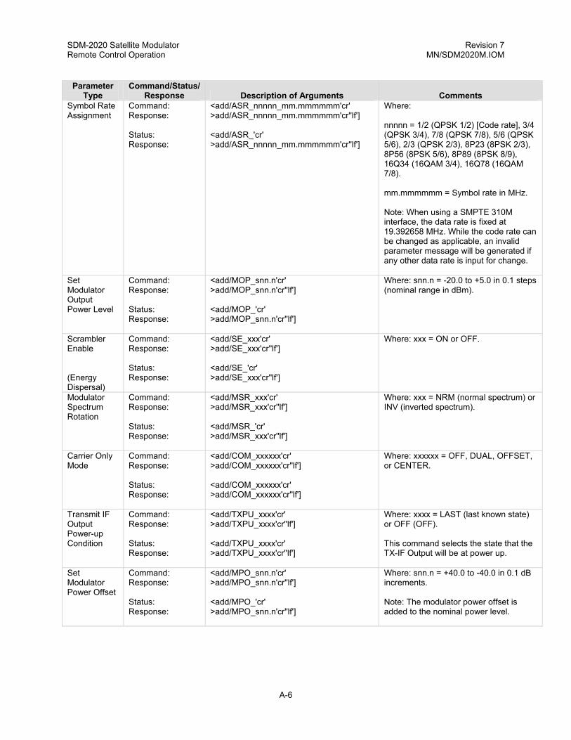
SDM-2020 Satellite Modulator Revision 7 Remote Control Operation MN/SDM2020M.IOM
Parameter Command/Status/ Type Response Description of Arguments Comments
Symbol Rate Assignment
Command: Response: Status: Response:
<add/ASR_nnnnn_mm.mmmmmm'cr' >add/ASR_nnnnn_mm.mmmmmm'cr''lf'] <add/ASR_'cr' >add/ASR_nnnnn_mm.mmmmmm'cr''lf']
Where: nnnnn = 1/2 (QPSK 1/2) [Code rate], 3/4 (QPSK 3/4), 7/8 (QPSK 7/8), 5/6 (QPSK 5/6), 2/3 (QPSK 2/3), 8P23 (8PSK 2/3), 8P56 (8PSK 5/6), 8P89 (8PSK 8/9), 16Q34 (16QAM 3/4), 16Q78 (16QAM 7/8). mm.mmmmmm = Symbol rate in MHz. Note: When using a SMPTE 310M interface, the data rate is fixed at 19.392658 MHz. While the code rate can be changed as applicable, an invalid parameter message will be generated if any other data rate is input for change.
Set Modulator Output Power Level
Command: Response: Status: Response:
<add/MOP_snn.n'cr' >add/MOP_snn.n'cr''lf'] <add/MOP_'cr' >add/MOP_snn.n'cr''lf']
Where: snn.n = -20.0 to +5.0 in 0.1 steps (nominal range in dBm).
Scrambler Enable (Energy Dispersal)
Command: Response: Status: Response:
<add/SE_xxx'cr' >add/SE_xxx'cr''lf'] <add/SE_'cr' >add/SE_xxx'cr''lf']
Where: xxx = ON or OFF.
Modulator Spectrum Rotation
Command: Response: Status: Response:
<add/MSR_xxx'cr' >add/MSR_xxx'cr''lf'] <add/MSR_'cr' >add/MSR_xxx'cr''lf']
Where: xxx = NRM (normal spectrum) or INV (inverted spectrum).
Carrier Only Mode
Command: Response: Status: Response:
<add/COM_xxxxxx'cr' >add/COM_xxxxxx'cr''lf'] <add/COM_xxxxxx'cr' >add/COM_xxxxxx'cr''lf']
Where: xxxxxx = OFF, DUAL, OFFSET, or CENTER.
Transmit IF Output Power-up Condition
Command: Response: Status: Response:
<add/TXPU_xxxx'cr' >add/TXPU_xxxx'cr''lf'] <add/TXPU_xxxx'cr' >add/TXPU_xxxx'cr''lf']
Where: xxxx = LAST (last known state) or OFF (OFF). This command selects the state that the TX-IF Output will be at power up.
Set Modulator Power Offset
Command: Response: Status: Response:
<add/MPO_snn.n'cr' >add/MPO_snn.n'cr''lf'] <add/MPO_'cr' >add/MPO_snn.n'cr''lf']
Where: snn.n = +40.0 to -40.0 in 0.1 dB increments. Note: The modulator power offset is added to the nominal power level.
A-6

SDM-2020 Satellite Modulator Revision 7 Remote Control Operation MN/SDM2020M.IOM
Parameter Command/Status/ Type Response Description of Arguments Comments
Modulator Type
Command: Response: Status: Response:
<add/MT_xxxx'cr' >add/MT_xxxx'cr'lf'] <add/MT_xxxx'cr' >add/MT_xxxx'cr'lf']
Where: xxxx = DVB1 or DVB2.
A.2.2 BULK MODULATOR CONFIGURATION
Parameter Type
Command/Status/
Response Description of Arguments Comments Bulk Modulator Config
Command: Response: Status: Response:
<add/BMC_p1,p2,p3,…..pn'cr' >add/BCM_p1,p2,p3, . . . pn'cr''lf'] <add/BMC_'cr' <add/BMC_p1,p2,p3,…..pn'cr''lf']
This command causes the modulator to be programmed with supplied parameters. All parameters are separated by a ',' except for the last parameter which has the standard command termination character ('cr'). Parameters that do not need to be changed can be nulled (no data between commas). Note: This is the only command that may be issued without first invoking the remote command ("<add/REM_"). The remote command is part of the initialization of this BMC_command. Status requests to not require that the remote command be issued at all. Where'pn' is the last parameter returned.
A-7

SDM-2020 Satellite Modulator Revision 7 Remote Control Operation MN/SDM2020M.IOM
A-8
BMC Parameters 1 to 33
Parameter Number 1 2 3 4 5 6 7 8 9 10 11 12 13 14 15 16 17 18 through 22 23 through 40
Parameter Name (Command Reference) Modulator Rate Assignment (ref."AMRV_"command) Modulator IF Frequency (ref. 'MF_' command). Modulator RF Output (ref. 'RF_' command). Modulator Output Power Level (ref. 'MOP_' command). Modulator Power Offset (ref. 'MPO_' command). Carrier Only Mode (ref. 'COM_' command). Modulator Spectrum Rotation (ref. 'MSR_' command). TX Output Power-up Configuration (ref. 'TXPU_' command). Modulator Type (ref. 'MT_' command). Scrambler Enable (ref. 'SE_' command). Transit Clock Phase (ref. 'TCP_' command). Transmit Data Phase (ref. 'TDP_' command). Transmit 2047 pattern generator (ref. 'ISP_' command). Transmit Sync Select (ref. 'SYNC_' command). Transit Data Fault Mode (ref. ‘ TDF_’command) Transmit Clock Activity Action (ref. 'TCAA_' command). DVB Framing Type (ref. 'TDVB_' command). Reserved Interface Specific
Description p1 = nnnnn-mmm.mmmmmm, code rate/date rate in Mbps p2 = nnn.nnnn, IF frequency in MHz p3 = n, where n is 0 or 1 (0 = Off, 1 = On). p4 = snn.n, transmitter output power level in dBm. p5 = snn.n, transmitter power offset level in dBm. p6 = n, where n is 0, 1, 2, 3 (0 = Off, 1 = Dual, 2 = Offset, 3 = Center) p7 = n, where n is 0 or 1 (0 = NRM, 1 =INV) p8 = n, where 'n' is '0' or ‘1’ (0 = Off, 1 = Last) p9 = n, where 'n' is '0' or ‘1’ (0 = DVB-1, 1 = DVB-2) p10 = n, where 'n' is ’0’ or ‘1’ (0 = Off , 1 = On) p11 = n, where 'n' = ‘0’ or ‘1’ (0 = NRM, 1 = INV) p12 = n, where 'n' = ‘0’ or ‘1’ (0 = NRM, 1 = INV) p13 = n, where ‘n’ is ‘0’ or ‘1’ (0 = Off, 1 = On) p14 = n, where ‘n’ is ‘0’, ‘1’, ‘2’ (0 = EXT, 1 = Data, 2 = Auto) p15 = n, where ‘n’ is ‘0’, ‘1’, ‘2’ (0 = None, 1 = Data Stable, 2 = AIS) p16 = n, where 'n' is '0' or ‘1’ (0 = Fault, 1 = Alarm) p17 = n, where n = '1' , ‘2’, ‘3’ (1 = 188, 2 = None, 3 = 204)

SDM-2020 Satellite Modulator Revision 7 Remote Control Operation MN/SDM2020M.IOM
A.2.2.1 RS-422 INTERFACE
Parameter Type
Command/Status/
Response Description of Arguments Comments BMC Parameters 23 to 40
23 24 25 26 27 28 29 thru 40
Interface Select Mode (ref. 'ISEL_' command). Interface Clock Mode (ref. ‘ICLK_' command). RTS TX-IF Control Mode (ref ‘RTSM_' command). RTS State Control (ref 'RTSS_' command). CTS State Control (ref ‘CTSS_' command). DM State Control (ref. ‘DM_’command). Reserved
p23 = n, where n = '0' (DVB, 1 =530) p24 = n, where n = '0' (Serial), '1' (Parallel). p25 = n, where n = '0' (Off), '1' (On). p26 = n, where n = '0' (Normal), '1' (Invert). p27 = n, where n = '0' (Normal), '1' (Invert). P28 = n, where n = ‘0’(Normal), ‘1’ (Invert)
A.2.2.2 LVDS INTERFACE
Parameter Type
Command/Status/
Response Description of Arguments Comments BMC Parameters 23 to 40
23 24 thru 40
Interface Clock Mode (ref. ‘ICLK_' command). Reserved
p23 = n, where n = '0' (Serial), '1' (Parallel).
A-9

SDM-2020 Satellite Modulator Revision 7 Remote Control Operation MN/SDM2020M.IOM
A.2.2.3 ASI/RS-422 INTERFACE
Parameter Type
Command/Status/
Response Description of Arguments Comments BCS Parameters 23 to 40
23 24 25 26 27 28 29 30 31 32 33 to 40
Interface Select Mode (ref. 'ISEL_' command). RTS TX-IF Control Mode (ref. 'RTSM_' command). RTS State Control (ref 'RTSS_' command). CTS State Control (ref 'CTSS_' command). DM State Control (ref 'DMS_' command). ST State Control (ref 'ST_' command). ASI Input Control (ref 'ASI_' command). ASI Loop Bandwith Control (ref ‘ASLB_’command). Interface Loopback (ref. ‘ILB_”command). Interface Loop Thru Control (ref. ‘ILM_”command). Reserved
p23 = n, where n = '0' (ASI), '1' (RS422). p24 = n, where n = '0' (Off), '1' (On). p25 = n, where n = '0' (Normal), '1' (Invert). p26 = n, where n = '0' (Normal), '1' (Invert). p27 = n, where n = '0' (Normal), '1' (Invert). p28 = n, where n = '0' (Normal), '1' (Invert). p29 = n, where n = 'A' (A-Input), 'B' (B-Input). p30 = n, where n = '0' (Wide), '1' (Narrow). p31 = n, where n = ‘0’ (Off), ‘1’ (On). p32 = n, where n = ‘0’ (Off), ‘1’ (On).
A-10

SDM-2020 Satellite Modulator Revision 7 Remote Control Operation MN/SDM2020M.IOM
A.2.2.4 ASI/LVDS INTERFACE
Parameter Type
Command/Status/
Response Description of Arguments Comments BCS Parameters 23 to 40
23 24 25 26 27 28 29 30 31 and 40
Interface Select Mode (ref. 'ISEL_' command). RTS TX-IF Control Mode (ref. 'RTSM_' command). RTS State Control (ref 'RTSS_' command). ASI Input Control (ref 'ASI_' command). ASI Loop Bandwidth Control (ref 'ASLB_' command). Interface Loopback (ref ‘ILB_’command). Interface Loop Thru Control (ref ‘ILM_’command) ASI Link Mode Control (ref ‘ASIA_’command) Reserved.
p23 = n, where n = '0' (ASI), '1' (LVDS). p24 = n, where n = '0' (Off), '1' (On). p25 = n, where n = '0' (Normal), '1' (Invert). p26 = n, where n = '0' (A-Input), '1' (B-Input). p27 = n, where n = '0' (Wide), '1' (Narrow). p28 = n, where n = '0' (Off), '1' (On). P29 = n, where n = '0' (Off), '1' (On). P30 = n, where n = ‘0’ (Manual), ‘1’ (Auto)
A.2.2.5 SMPTE-310 INTERFACE
Parameter Type
Command/Status/
Response Description of Arguments Comments BCS Parameters 23 to 40
23 24 25 26 27 to 40
RTS TX-IF Control Mode (ref ‘RTSM_’command) Interface Loopback (ref ‘RTSS_’command) Interface Loopback (ref: 'ILB_' command). RTS State Control (ref “ILM_”command) Reserved.
p23 = n, where n = ‘0’ (OFF) or ‘1’ (ON) p24 = n, where n = ‘0’ (Normal) or ‘1’ (Invert). p25 = n, where n = ‘0’ (OFF) or ‘1’ (ON). P26 = n where n = ‘0’ (OFF) or ‘1’ (ON)
A-11

SDM-2020 Satellite Modulator Revision 7 Remote Control Operation MN/SDM2020M.IOM
A.2.2.6 G.703 INTERFACE
Parameter Type
Command/Status/
Response Description of Arguments Comments BCS Parameters 23 to 40
23 24 25 26 27 28 to 40
TX Interface Coding Format (ref ‘ICFT_’command) RTS TX-IF Control Mode (ref ‘RTSM_’command) RTS State Control (ref: 'RTSS_' command). Interface Loopback (ref “ILB_”command) Interface Loop Thru Control (ref ‘ILM_’command) Reserved
p23 = n, where n = ‘0’ (AMI), ‘1’ (B3ZS), ‘2’ (HDB3), ‘3’ (B8ZS). p24 = n, where n = ‘0’ (Off) or ‘1’ (On). p25 = n, where n = ‘0’ (Normal) or ‘1’ (Invert). p26 = n where n = ‘0’ (OFF) or ‘1’ (ON). p27 = n where n = ‘0’ (OFF) or ‘1’ (ON).
A.2.2.7 ECL/HSSI INTERFACE
Parameter Type
Command/Status/
Response Description of Arguments Comments BCS Parameters 23 to 40
23 24 25 26 to 40
DTE TX-IF Control Mode (ref. 'DTEM_' command). DTE State Control (ref “DTES_”command). DCE State Control (ref “DCES_”command). Reserved.
p23 = n, where n = '0' (Off), '1' (On). P24 = n, where n ='0' (Normal), '1' (Invert). P25 = n, where n = '0' (zNormal), '1' (Invert).
A.2.3 BULK MODULATOR CONFIGURATION CHANGE STATUS
Parameter Type
Command/Status/ Response
Description of Arguments Comments
Bulk Modulator Config Change Status
Status: Response:
<add/BMCS_'cr' >add/BMCS_x'cr''lf']
The ‘x’ character is defined as follows: ‘@’ = No change since last BMC_ poll. ‘A’ = BMC_ response has changed since last BMC_ poll. This command indicates that a change has or has not occurred on the BMC_ response since the last BMC_poll.
A-12

SDM-2020 Satellite Modulator Revision 7 Remote Control Operation MN/SDM2020M.IOM
A.2.4 BULK MODULATOR CONFIGURATION ERRORS
Parameter Type
Command/ Status/
Response Description of Arguments Comments Bulk Modulator Config Errors
Command: Response:
<add/BMCE_'cr' >add/BCM_p1,p2,p3, . . . pn40'cr''lf']
When the BCME_command is executed, the host M&C will inspect all of the supplied parameters of the Bulk Modulator Command (BMC_) for failure. If any particular parameter or any combination of parameters is invalid or out of range, the resulting output error listing will allow the user to evaluate which parameters caused the error. The output error listing is a series of 40 characters, which are either a 1 or a 0, commas delimited. A listing of all 0 would indicate that there were no errors. A 1 in position 1 and position 17 might indicate that the symbol range of the modulator was exceeded (Data and Code Rate are programmed in position 1 and framing type which affects symbol rate would be position 17). This command is a status request only, and is cleared after another BMC_ command is issued. The BMCE_command will alaways report the status of all 40 parameters, whether these parameters are used or reserved. Note: Parameters 23 through 40 are interface dependent. Ensure to refer to the BMC_command for the particular type of interface that is installed in the modulator. Where'pn40' is the last parameter returned.
A-13

SDM-2020 Satellite Modulator Revision 7 Remote Control Operation MN/SDM2020M.IOM
A.2.5 INTERFACE CONFIGURATION COMMANDS
Parameter Type
Command/ Status/
Response Description of Arguments Comments Transmit Clock Phase
Command: Response: Status: Response:
<add/TCP_xxx'cr' >add/TCP_xxx'cr''lf'] <add/TCP_'cr' >add/TCP_xxx'cr''lf']
Where: xxx = NRM (normal clock phasing) or INV (inverted clock phasing).
Transmit Data Phase
Command: Response: Status: Response:
<add/TDP_xxx'cr' >add/TDP_xxx'cr''lf'] <add/TDP_'cr' >add/TDP_xxx'cr''lf']
Where: xxx = NRM (normal data phasing) or INV (inverted data phasing).
Interface Substitution Pattern
Command: Response: Status: Response:
<add/ISP_xxx'cr' >add/ISP_xxx'cr''lf'] <add/ISP_'cr' >add/ISP_xxx'cr''lf']
Where: xxx = On or Off. Note: Transmit 2047 Pattern.
DVB Sync Selection
Command: Response: Status: Response:
<add/SYNC_xxxx'cr' >add/SYNC_xxxx'cr''lf'] <add/SYNC_'cr' >add/SYNC_xxxx'cr''lf']
Where: xxxx = EXT (sync pulse), DATA (data sync byte), AUTO. Note: Data is only allowed with the ASI/LVDS interface operating in ASI mode.
Transmit Data Fault
Command: Response: Status: Response:
<add/TDF_xxxx'cr' >add/TDF_xxxx'cr''lf'] <add/TDF_'cr' >add/TDF_xxxx'cr''lf']
Where: xxxx = NONE, DATA, AIS.
DVB Framing Type
Command: Response: Status: Response:
<add/TDVB_xxxx'cr' >add/TDVB_xxxx'cr''lf'] <add/TDVB_'cr' >add/TDVB_xxxx'cr''lf']
Where: xxxx = 188, 204, NONE.
Interface Identification
Status: Response:
<add/INID_'cr' >add/INID_xxxxxxx'cr''lf']
Where: xxxxxxxxx = RS422, LVDS, ASI_RS422, ECL_TX, G.703, SMPTE 310M, ASI/LVDS, or UNKNOWN.
Interface Mode Config.
Command: Response: Status: Response:
<add/ICLK_xxx'cr' >add/ICLK_xxx'cr''lf'] <add/ICLK_'cr' >add/ICLK_xxx'cr''lf']
Where: xxx = SER (Serial mode, CLK = Data rate) or PAR (Parallel mode CLK = Data rate/8).
A-14
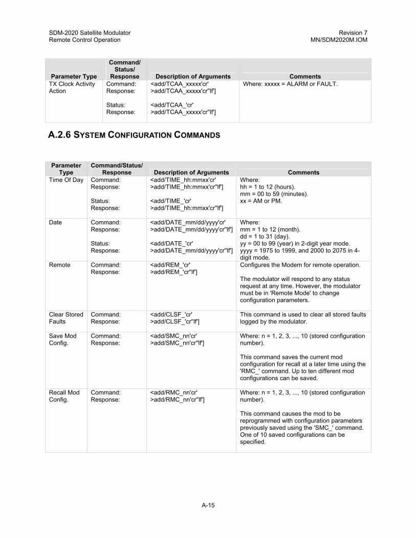
SDM-2020 Satellite Modulator Revision 7 Remote Control Operation MN/SDM2020M.IOM
Command/ Status/
Parameter Type Response Description of Arguments Comments TX Clock Activity Action
Command: Response: Status: Response:
<add/TCAA_xxxxx'cr' >add/TCAA_xxxxx'cr''lf'] <add/TCAA_'cr' >add/TCAA_xxxxx'cr''lf']
Where: xxxxx = ALARM or FAULT.
A.2.6 SYSTEM CONFIGURATION COMMANDS
Parameter
Type Command/Status/
Response Description of Arguments Comments Time Of Day Command:
Response: Status: Response:
<add/TIME_hh:mmxx'cr' >add/TIME_hh:mmxx'cr''lf'] <add/TIME_'cr' >add/TIME_hh:mmxx'cr''lf']
Where: hh = 1 to 12 (hours). mm = 00 to 59 (minutes). xx = AM or PM.
Date Command: Response: Status: Response:
<add/DATE_mm/dd/yyyy'cr' >add/DATE_mm/dd/yyyy'cr''lf'] <add/DATE_'cr' >add/DATE_mm/dd/yyyy'cr''lf']
Where: mm = 1 to 12 (month). dd = 1 to 31 (day). yy = 00 to 99 (year) in 2-digit year mode. yyyy = 1975 to 1999, and 2000 to 2075 in 4-digit mode.
Remote Command: Response:
<add/REM_'cr' >add/REM_'cr''lf']
Configures the Modem for remote operation. The modulator will respond to any status request at any time. However, the modulator must be in 'Remote Mode' to change configuration parameters.
Clear Stored Faults
Command: Response:
<add/CLSF_'cr' >add/CLSF_'cr''lf']
This command is used to clear all stored faults logged by the modulator.
Save Mod Config.
Command: Response:
<add/SMC_nn'cr' >add/SMC_nn'cr''lf']
Where: n = 1, 2, 3, ..., 10 (stored configuration number). This command saves the current mod configuration for recall at a later time using the 'RMC_' command. Up to ten different mod configurations can be saved.
Recall Mod Config.
Command: Response:
<add/RMC_nn'cr' >add/RMC_nn'cr''lf']
Where: n = 1, 2, 3, ..., 10 (stored configuration number). This command causes the mod to be reprogrammed with configuration parameters previously saved using the 'SMC_' command. One of 10 saved configurations can be specified.
A-15

SDM-2020 Satellite Modulator Revision 7 Remote Control Operation MN/SDM2020M.IOM
Parameter Command/Status/ Type Response Description of Arguments Comments
Alarm Relay State
Command: Response: Status: Response:
<add/ARLY_xxx'cr' >add/ARLY_xxx'cr''lf'] <add/ARLY_'cr' >add/ARLY_xxx'cr''lf']
Where: xxx = NRM (normal sense) or INV (inverted sense). This command controls the logic sense of the Mod alarm relay (NC and NO contacts).
A.3 STATUS COMMANDS/RESPONSES
A.3.1 CONFIGURATION STATUS
Parameter
Type Command/Status/
Response Description of Arguments Comments Modulator Rate
Command: Response:
<add/MR_'cr' >add/MR_nnnnn_mmm.mmmmmm'cr''lf']
Where: nnnnn = 1/2 (QPSK 1/2) [Coder rate], 3/4 (QPSK 3/4) 7/8 (QPSK 7/8), 5/6 (QPSK 5/6), 2/3 (QPSK 2/3), 8P23 (8PSK 2/3), 8P56 (8PSK 5/6), 8P89 (8PSK 8/9), 16Q34 (16QAM 3/4), 16Q78 (16QAM 7/8). mmm.mmmmmm = Data rate in MHz. Note: When using a SMPTE 310M interface, the data rate is fixed at 19.392658 MHz. While the code rate can be changed as applicable, an invalid parameter message will be generated if any other data rate is input for change.
A-16

SDM-2020 Satellite Modulator Revision 7 Remote Control Operation MN/SDM2020M.IOM
Parameter Command/Status/ Type Response Description of Arguments Comments
Modulator Config. Status
Command: Response:
<add/MCS_'cr' >add/MCS_'cr' RF_xxx'cr' MF_nnn.nnnn'cr' MR_nnnn_mmm.mmmmmm'cr' AMRA_nnnn_mmm.mmmmmm'cr' AMRV_nnnn_mmm.mmmmmm'cr' MPO_snn.n'cr' MOP_snn.n'cr' SE_xxx'cr' COM_xxxxxx'cr' MSR_xxx'cr' MT_xxxx'cr' TXPU_xxxxx'cr''lf']
RF Output (ON/OFF) Modulator Frequency Modulator Rate Modulator Rate Modulator Rate Modulator Power Offset Modulator Output Power Scrambler Enable (ON/OFF) Carrier Only Mode Modulator Spectrum Rotation Modulator Type Transmit IF Output Power-up Configuration The Modulator configuration status command causes a block of data to be returned by the addressed mod. The block of data reflects the current configuration status of the modulator module. Additional configuration status of new options and features will always be appended to the end.
Modulator/ Coder Config. Program Status
Note: This command is used by Comtech EFData M:N protection switch to collect information that is necessary to configure back-up modulators. Because this command (content and/or order) can be changed at any time by Comtech EFData, it is advisable that other commands (“MCS_”, “ICS_”, or “BCS_”) be used for M&C systems. This command varies depending on the installed interface. The command is located in the interface sections.
Interface Config. Status
Note: The interface configuration status command causes a block of data to be returned by the addressed MODEM. The block reflects the current configuration of the interface. Additional configuration status of new options and features will always be appended to the end. This command varies depending on the installed interface. This command is located in the interface sections.
Modem Faults Status (Summary)
Command: Response:
<add/MFS_'cr' >add/MFS_'cr' MOD_xxx'cr' ITX_xxx'cr' CEQ_xxx'cr''lf']
Modulator (FLT/OK) Interface Transmit Side (FLT/OK) Common Equipment (FLT/OK)
Modulator Status
Command: Response:
<add/MS_'cr' >add/MS_'cr' RF_xxx'cr' MOD_xxx'cr' SYN_xxx'cr' DCS_xxx'cr' ICH_xxx'cr' QCH_xxx'cr' AGC_xxx'cr' IF_xxx'cr' CONF_xxx'cr' SFLT_xx'cr''lf']
RF Output (ON/OFF) Actual status not config. Module (OK/FLT) IF Synthesizer (OK/FLT) Data Clock Synthesizer (OK/FLT) I Channel (OK/FLT) Q Channel (OK/FLT) AGC Level (OK/FLT) IF Module Fault (OK/FLT) Configuration Fault (OK/FLT) Number of Stored Faults Logged (0 to 10)
A-17

SDM-2020 Satellite Modulator Revision 7 Remote Control Operation MN/SDM2020M.IOM
Parameter Command/Status/ Type Response Description of Arguments Comments
Interface Status
Command: Response:
<add/ITXS_'cr' >add/ITXS_'cr' FSYN_xxx'cr' TXD_xxx'cr' PLL_xxx'cr' CLK_xxx'cr' FIFO_xxx'cr' INT_xxx'cr' DF_xxx'cr' VSYN_xxx'cr' SFLT_xx'cr''lf']
Frame Sync Lock (OK/FLT) Transmit Data (OK/FLT) Transmit Synthesizer PLL Lock (OK/FLT) Transmit Clock Activity (OK/FL) Transmit FIFO (OK/FLT) Interface Module (OK/FLT) Data Format (OK/FLT) Video Frame Sync (OK/FLT) Number of Stored Faults Logged (0 to 10)
A.4 COMMON EQUIPMENT STATUS
This common equipment status command causes a block of data to be returned which indicates the status of the common equipment .
Parameter Type Command/Status/
Response Description of
Arguments Comments Common Equipment Status
Command: Response:
<add/CES_’’ cr’ >add/CES_’cr’ M&C_xxx'cr' BAT_xxx'cr' +5_xxx'cr' +12_xxx'cr' -12_xxx'cr' MODE_xxxxxx'cr' SFLT_xx'cr'’If”]
Monitor & Control Module (OK/FLT) Battery/Clock (OK/FLT) +5 volt power supply (OK/FLT) +12 volt power supply (OK/FLT) -12 volt power supply (OK/FLT) Mode (LOCAL or REMMOTE) Number of stored faults logged (0 to 10)
A.5 STORED FAULTS STATUS
Information on stored faults is returned when requested. If no stored fault exists for a given fault number, the words “NO Fault” will be returned instead of the normal time/date status information. The following symbols are commonly used to define the stored faults status commands:
# Fault number (0 to 9). “0” is the first fault stored. hh Hours in 24-hr. format. mm Minutes. ss Seconds. MM Month. DD Day. YY or YYYY Year (2- or 4-digits)
A-18

SDM-2020 Satellite Modulator Revision 7 Remote Control Operation MN/SDM2020M.IOM
Parameter Type Command/Status/
Response Description of Arguments Comments Modulator Stored Faults Command:
Response: <add/MSF_#'cr' >add/MSF_# hh:mm:ss MM/DD/YYYY'cr' MOD_xxx'cr' SYN_xxx'cr' DCS_xxx'cr' ICH_xxx'cr' QCH_xxx'cr' AGC_xxx'cr' IF_xxx'cr' CONF_xxx'cr''lf']
Module (OK/FLT) IF Synthesizer (OK/FLT) Data Clock Synthesizer (OK/FLT) I Channel (OK/FLT) Q Channel (OK/FLT) AGC Level (OK/FLT) IF Module Fault (OK/FLT) Configuration (OK/FLT)
Interface Transmit Side Stored Faults
Command: Response:
<add/ITSF_#'cr' >add/ITSF_# hh:mm:ss MM/DD/YYYY'cr' FSYN_xxx'cr' TXD_xxx'cr' PLL_xxx'cr' CLK_xxx'cr' FIFO_xxx'cr' INT_xxx'cr' DF_xxx'cr''lf'] VSYN_xxx'cr''lf']
Frame Sync Lock (OK/FLT) Transmit Data (OK/FLT) Transmit Synthesizer PLL Lock (OK/FLT) Transmit Clock Activity (OK/FL) Transmit FIFO (OK/FLT) Interface Module (OK/FLT) Data Format (OK/FLT) Video Sync (OK/FLT)
Common Equipment Stored Faults
Command: Response:
<add/CSF_#'cr' >add/CSF_# hh:mm:ss MM/DD/YYYY'cr' M&C_xxx'cr' BAT_xxx'cr' +5_xxx'cr' +12_xxx'cr' -12_xxx'cr''lf']
Monitor & Control Module (OK/FLT) Battery/Clock (OK/FLT) +5V Power Supply (OK/FLT) +12V Power Supply (OK/FLT) -12V Power Supply (OK/FLT)
A-19

SDM-2020 Satellite Modulator Revision 7 Remote Control Operation MN/SDM2020M.IOM
A.5.1 BULK CONSOLIDATED STATUS
Parameter
Type Command/Status/
Response Description of Arguments Comments
Bulk Consol. Status
Command: Response:
<add/BCS_'cr' >add/BCS_p1,p2,p3, . . . pn'cr''lf']
This command causes bulk mod status to be returned. To reduce the length of the response, message parameter data are returned without identifiers. However, parameter identification can be determined by order of return. Each status parameter is terminated with a ',' (comma) except for the last parameter which has the standard message termination sequence ('cr''lf']). Most of the data returned is formatted the same way as the single command status request (refer to the appropriate portions of this document in preceding sections). Additional configuration status of new options and features will always be appended to the end.
A-20

SDM-2020 Satellite Modulator Revision 7 Remote Control Operation MN/SDM2020M.IOM
Parameter
Number Parameter Name
(Command Reference) Description BCS Parameters 1 to 33
1 2 3 4 5 6 7 8 9 10 11 12 13 14 15 16 17 18
Modem Remote/Local mode Modulator RF Output (ref. 'RF_' command). Modulator IF Frequency (ref. 'MF_' command). Modulator Rate (ref. 'MR_' command). Modulator Rate (ref. 'ASR_' command). Modulator Power Offset (ref. 'MPO_' command). Modulator Output Power Level (ref. 'MOP_' command). Scrambler Enable (ref. 'SE_' command). TX Output Power-up Configuration (ref. 'TXPU_' command). Carrier Only Mode (ref. 'COM_' command). Modulator Type (ref. 'MT_' command). Transmit Clock Phase (ref. 'TCP_' command). Transmit Data Phase (ref. 'TDP_' command). Transmit Data Phase (ref. 'TDF_' command). Transmit 2047 Pattern Generator (ref. 'ISP_' command). Transmit Clock Phase (ref. 'SYNC_' command). DVB Framing Type (ref. 'TDVB_' command). Modulator Spectrum Rotation (ref. 'MSR_' command).
p1 = n, where 'n' is '0' (LOCAL) or '1' (REMOTE). p2 = n, where 'n' is '0' (Off) or '1' (On). p3 = nnn.nnnn, IF frequency in MHz. p4 = nnnn_mmm.mmmmmm, code rate/data rate in Mbps. p5 = nnnn_mm.mmmmmm, code rate/symbol rate in Msps. p6 = snn.n, transmitter power offset level in dBm. p7 = snn.n, transmitter output power in dBm. p8 = n, where 'n' is '0' (off) or '1' (on). p9 = n, where 'n' is '0' (off) or '1' (last). p10 = n, where 'n' is '0' (Off), '1' (Dual),' 2' (Offset), or '3' (Center). p11 = n, where 'n' = '0' (DVB-1) or '1' (DVB-2). p12 = n, where 'n' is '0' (NRM), '1' (INV), or '2'. p13 = n, where 'n' is '0' (NRM) or '1' (INV). p14 = n, where 'n' is '0' (None), '1' (Data stable), or '2' (AIS). p15 = n, where 'n' is '0' (off) or '1' (on). p16 = n, where 'n' is '0' (EXT), '1' (DATA), or '2' (AUTO). p17 = n, where n = '1' (188), '2' (NONE), or '3' (204). p18 = n, where 'n' is '0' (NRM) or '1' (INV).
A-21

SDM-2020 Satellite Modulator Revision 7 Remote Control Operation MN/SDM2020M.IOM
Parameter
Number Parameter Name
(Command Reference) Description
19 and 20 21 22 23 to 32 33
Reserved. Interface ID (ref. 'INID_' command). Interface clock Mode (ref. 'ICLK_' command). Interface specific. TX Clock Activity Action (ref. 'TCAA' command).
p21 = 'xxxxxxx', where xxxxxxx = Interface type. p22 = n, where n = '0' (Serial) or '1' (Parallel). p33 = n, where n = '0' (Fault), '1' (Alarm).
A.5.2 BULK CONSOLIDATED STATUS FAULTS
Parameter Type
Command/ Status/
Response Description of Arguments Comments Bulk Consol. Status Faults
Command: Response:
<add/BCSF_'cr' >add/BCSF_abcdefghijklmnop'cr''lf']
This command causes all mod fault status to be returned. To reduce the length of the response, fault status is embedded into the bit structure of the characters that are returned. Faults are indicated by a binary 1 in the designated bit position. Additional fault status of new options and features will be appended to the end or use existing reserved bits. Character 'a': Modulator fault status character 1.
Bit 6 = 1 always. Bit 5 = Modulator module fault. Bit 4 = RF output status, actual not programmed status (1 = on, 0 = off). Bit 3 through Bit 0 = Binary representation (0 to 10) of the number of modulator stored faults.
Character 'b': Modulator fault status character 2.
Bit 6 = 1 always. Bit 5 = IF Synthesizer. Bit 4 = Data Clock Synthesizer. Bit 3 = I Channel. Bit 2 = Q Channel. Bit 1 = AGC Level. Bit 0 = Configuration.
Character 'c': Modulator fault status character 3.
Bit 6 = 1 always. Bit 5 = IF module. Bit 4 through Bit 0 reserved.
A-22

SDM-2020 Satellite Modulator Revision 7 Remote Control Operation MN/SDM2020M.IOM
Parameter Command/
Status/ Type Response Description of Arguments Comments
Character 'd': Interface transmit side faults character 1.
Bit 6 = 1 always. Bit 5 = Data Format Fault Bit 4 = reserved. Bit 3 through Bit 0 = Binary representation (0 to 10) of the number of interface transmit side stored faults.
Character 'e': Interface transmit side faults character 2.
Bit 6 = 1 always. Bit 5 = Frame Sync Lock. Bit 4 = Transmit Data Valid. Bit 3 = Transmit Clock Activity. Bit 2 = Transmit Synthesizer PLL Lock. Bit 1 = Transmit FIFO. Bit 0 = Interface module fault
Character 'f': Interface transmit side faults character 3.
Bit 6 = 1 always. Bit 5 through Bit 0 reserved.
Character 'g': Common equipment fault status character 1.
Bit 6 = 1 always. Bit 5 = reserved. Bit 4 through Bit 0 = Binary representation (0 to 10) of the number of common equipment stored faults.
Character 'h': Common equipment fault status character 2.
Bit 6 = 1 always. Bit 5 = Battery/Clock. Bit 4 = +5V power supply. Bit 3 = +12V power supply. Bit 2 = -12V power supply. Bit 1 = Monitor & Control Module. Bit 0 = reserved.
A-23
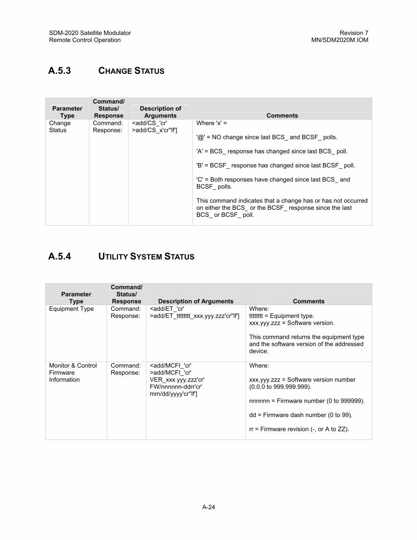
SDM-2020 Satellite Modulator Revision 7 Remote Control Operation MN/SDM2020M.IOM
A.5.3 CHANGE STATUS
Parameter Type
Command/ Status/
Response Description of
Arguments Comments Change Status
Command: Response:
<add/CS_'cr' >add/CS_x'cr''lf']
Where 'x' = '@' = NO change since last BCS_ and BCSF_ polls. 'A' = BCS_ response has changed since last BCS_ poll. 'B' = BCSF_ response has changed since last BCSF_ poll. 'C' = Both responses have changed since last BCS_ and BCSF_ polls. This command indicates that a change has or has not occurred on either the BCS_ or the BCSF_ response since the last BCS_ or BCSF_ poll.
A.5.4 UTILITY SYSTEM STATUS
Parameter Type
Command/ Status/
Response
Description of Arguments
Comments Equipment Type Command:
Response: <add/ET_'cr' >add/ET_tttttttt_xxx.yyy.zzz'cr''lf']
Where: tttttttt = Equipment type. xxx.yyy.zzz = Software version. This command returns the equipment type and the software version of the addressed device.
Monitor & Control Firmware Information
Command: Response:
<add/MCFI_'cr' >add/MCFI_'cr' VER_xxx.yyy.zzz'cr' FW/nnnnnn-ddrr'cr' mm/dd/yyyy'cr''lf']
Where: xxx.yyy.zzz = Software version number (0.0.0 to 999.999.999). nnnnnn = Firmware number (0 to 999999). dd = Firmware dash number (0 to 99). rr = Firmware revision (-, or A to ZZ).
A-24

SDM-2020 Satellite Modulator Revision 7 Remote Control Operation MN/SDM2020M.IOM
Parameter
Command/ Status/
Type Response Description of Arguments Comments Boot Firmware Information
Command: Response:
<add/BFI_'cr' >add/BFI_'cr' Ver:_xxx_yyy.zzz'cr' FW/nnnnnn-ddrr’cr' mm/dd/yyyy'cr''lf']
Where: xxx.yyy.zzz = Software version number (0.0.0 to 999.999.999). nnnnnn = Firmware number (0 to 999999). dd = Firmware dash number (0 to 99). rr = Firmware revision (-, or A to ZZ).
Encoder Firmware Information (EFI)
Command: Response:
<add/EFI_'cr' >add/EFI_'cr' FW/nnnnn-ddrr'cr' Mm/dd/yyyy'cr''lf']
Where: nnnnn = Firmware number (0 to 65535). dd = Firmware dash number (0 to 99). rr = Firmware revision (-, or A to ZZ).
Reed-Solomon Firmware Information (RSFI)
Command: Response:
<add/RSFI_'cr' >add/RSFI_'cr' FW/nnnnn-ddrr'cr' Mm/dd/yyyy'cr''lf']
Where: nnnnn = Firmware number (0 to 65535). dd = Firmware dash number (0 to 99). rr = Firmware revision (-, or A to ZZ).
Interface Firmware Information (As Required)
Command: Response:
<add/IFI_'cr' >add/IFI_'cr' FW/nnnnn-ddrr'cr' mm/dd/yyyy'cr''lf']
Where: nnnnn = Firmware number (0 to 65535). dd= Firmware dash number (0 to 99). rr = Firmware revision (-, or A to ZZ).
Modem Options/ Misc. Information
Command: Response:
<add/MOI_'cr' >add/MOI_'cr' s,OEM_LCD'cr' s,16QAM'cr' s,8PSK'cr''lf']
Where: s = 0 (Not Installed, Not Upgradable) - = (Not Installed, FAST Upgradable) + = (Installed) (- or +) OEM LCD option (- or +) 16QAM Code Rate option (- or +) 8PSK Code Rate option
State of Product Command: Response:
<add/SOP_’cr’ >add/SOP_’cr’ Product address: abc’cr’ Baud format: abc’cr’ Baud rate: rrrrr bps’cr’ Comm type: <var-string1>’cr’ <varstring2>’cr’’lf’]
Where: a = Number of data bits (7) b = Parity type (O,E,N) c = Number of stop bits (1) rrrrr = baud rate (150, 300, 600, 1200, 2400, 4800, 9600, 14.4K, 19.2K) <var_string1> = Variable length strings explaining communication hardware type: RS-485, 2 wire RS-485, 4 wire RS-232 <var_string2> = Variable length strings explaining the intention of the product: “Under normal system operation” “REFLASH of BULK firmware required” “REFLASH of M&C firmware required”
A-25

SDM-2020 Satellite Modulator Revision 7 Remote Control Operation MN/SDM2020M.IOM
A.6 RS-422 INTERFACE COMMANDS
Parameter Type
Command/ Status/
Response Description
of Arguments Comments Interface Select Command
Command: Response: Status: Response:
<add/ISEL_xxxxxx'cr' >add/ISEL_xxxxxx'cr''lf'] <add/ISEL_'cr' >add/ISEL_xxxxxx'cr''lf']
This command is used for multiple interfaces: Where: Interface RS-422 xxxxxx = DVB or 530 Interface ASI/RS-422 xxxxxx = DVB or RS-422 Interfae ASI/LVDS xxxxxx = DVB or LVDS This command selects which interface connector will be used for data.
RTS TX-IF Control Mode
Command: Response: Status: Response:
<add/RTSM_xxx'cr' >add/RTSM_xxx'cr''lf'] <add/RTSM_'cr' >add/RTSM_xxx'cr''lf']
Where xxx = On or Off. This command configures the modem for the RTS TX-IF control mode. If ON is selected, the TX-IF output will only be turned On if the incoming RTS signal is asserted (also the TX-IF output has to be programmed ON and no major modulator faults are present). If OFF is selected, the TX-IF output will operate normal ignoring the RTS signal.
RTS State Control
Command: Response: Status: Response:
<add/RTSS_xxx'cr' >add/RTSS_xxx'cr''lf'] <add/RTSS_'cr' >add/RTSS_xxx'cr''lf']
Where xxx = NRM (Normal) or INV (Invert). This command controls the logic sense of the RTS signal.
CTS State Command: Response: Status: Response:
<add/CTSS_xxx'cr' >add/CTSS_xxx'cr''lf'] <add/CTSS_'cr' >add/CTSS_xxx'cr''lf']
Where xxx = NRM (Normal) or INV (Invert). This command control the logic sense of the CTS signal.
DM State Command: Response: Status: Response:
<add/DMS_xxx'cr' >add/DMS_xxx'cr''lf'] <add/DMS_'cr' >add/DMS_xxx'cr''lf']
Where xxx = NRM (Normal) or INV (Invert). This command controls the logic sense of the DM (DCS-ready) signal.
A-26

SDM-2020 Satellite Modulator Revision 7 Remote Control Operation MN/SDM2020M.IOM
Parameter Command/
Status/ Description Type Response of Arguments Comments
MCP Command Config.
Command: Response:
<add/MCP_'cr' >add/MCP_'cr' ISEL_xxxxxx'cr' ICLK_xxx'cr' TDVB_xxxx'cr' MF_nnn.nnnn'cr' MR_nnnn_mmm.mmmmmm'cr' MPO_snn.n'cr' MOP_snn.n'cr' SE_xxx'cr' TCP_xxx'cr' TDP_xxxx'cr' TDF_xxxx'cr' ISP_xxx'cr' SYNC_xxxx'cr' MSR_xxx'cr' MT_xxxx'cr' TXPU_xxxxx'cr' COM_xxxxxx'cr' RTSM_xxx'cr' RTSS_xxx'cr' CTSS_xxx'cr' DMS_xxx'cr' TCAA_xxxx'cr' RF_xxx'cr''lf']
Interface Select Interface Mode DVB Framing Type Modulator Frequency Modulator Rate Modulator Power Offset Modulator Output Power Scrambler Enable (ON/OFF) Transmit Clock Phase Transmit Data Phase Transmit Data Fault Transmit 2047 Pattern Generator Transmit Sync Select Modulator Spectrum Rotation Modulator Type Transmit IF Output Power-up Configuration Carrier Only Mode RTS Mode Control RTS State Control CTS State Control DMS State Control TX Clock Activity Action RF Output (ON/OFF)
ICS Command Config.
Command: Response:
<add/ICS_'cr' >add/ICS_'cr' TCP_xxx'cr' TDP_xxxx'cr' ISP_xxx'cr' SYNC_xxxx'cr' TDF_xxxx'cr' TDVB_xxxx'cr' INID_xxxxxxxxx'cr' ISEL_xxxxxx'cr' ICLK_xxx'cr' RTSM_xxx'cr' RTSS_xxx'cr' CTSS_xxx'cr' DMS_xxx'cr' TCAA_xxxxx'cr''lf']
Transmit Clock Phase Transmit Data Phase Transmit 2047 Pattern Generator Transmit Sync Select Transmit Data Fault DVB Framing Type Interface Identification Interface Select Interface Mode RTS Mode Control RTS State Control CTS State Control DM State Control TX Clock Activity Action
A-27

SDM-2020 Satellite Modulator Revision 7 Remote Control Operation MN/SDM2020M.IOM
Parameter Type
Command/Status/
Response Description of Arguments Comments BCS Parameters 23 to 32
23 24 25 26 27 28 thru 40
Interface Select (ref. 'ISEL_' command). RTS TX-IF Control Mode (ref ‘RTSM_' command). RTS State Control (ref 'RTSS_' command). CTS State Control (ref ‘CTSS_' command). DM State Control (ref. ‘DM_’command). Reserved
p23 = n, where n = '0' (DVB, 1 =530) p24 = n, where n = '0' (Off), '1' (On). p25 = n, where n = '0' (Normal), '1' (Invert). p27 = n, where n = '0' (Normal), '1' (Invert). P28 = n, where n = ‘0’(Normal), ‘1’ (Invert)
A.7 LVDS INTERFACE COMMANDS
Parameter
Type
Command/ Status/
Response
Description of Arguments
Comments MCP Command Config.
Command: Response:
<add/MCP_'cr' >add/MCP_'cr' ICLK_xxx'cr' TDVB_xxxx'cr' MF_nnn.nnnn'cr' MR_nnnn_mmm.mmmmmm'cr' MPO_snn.n'cr' MOP_snn.n'cr' SE_xxx'cr' TCP_xxx'cr' TDP_xxxx'cr' TDF_xxxx'cr' ISP_xxx'cr' SYNC_xxxx'cr' MSR_xxx'cr' MT_xxxx'cr' TXPU_xxxxx'cr' COM_xxxxxx'cr' TCAA_xxxxx'cr' RF_xxx'cr''lf']
Interface Mode DVB Framing Type Modulator Frequency Modulator Rate Modulator Power Offset Modulator Output Power Scrambler Enable (ON/OFF) Transmit Clock Phase Transmit Data Phase Transmit Data Fault Transmit 2047 Pattern Generator Transmit Sync Select Modulator Spectrum Rotation Modulator Type Transmit IF Output Power-up Configuration Carrier Only Mode TX Clock Activity Action RF Output (ON/OFF)
A-28
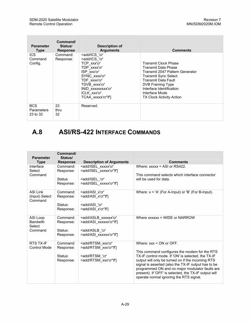
SDM-2020 Satellite Modulator Revision 7 Remote Control Operation MN/SDM2020M.IOM
Parameter
Command/ Status/
Description of
Type Response Arguments Comments ICS Command Config.
Command: Response:
<add/ICS_'cr' >add/ICS_'cr' TCP_xxx'cr' TDP_xxxx'cr' ISP_xxx'cr' SYNC_xxxx'cr' TDF_xxxx'cr' TDVB_xxxx'cr' INID_xxxxxxxxx'cr' ICLK_xxx'cr' TCAA_xxxxx'cr''lf']
Transmit Clock Phase Transmit Data Phase Transmit 2047 Pattern Generator Transmit Sync Select Transmit Data Fault DVB Framing Type Interface Identification Interface Mode TX Clock Activity Action
BCS Parameters 23 to 32
23 thru 32
Reserved.
A.8 ASI/RS-422 INTERFACE COMMANDS
Parameter Type
Command/ Status/
Response Description of Arguments Comments Interface Select Command
Command: Response: Status: Response:
<add/ISEL_xxxxx'cr' >add/ISEL_xxxxx'cr''lf'] <add/ISEL_'cr' >add/ISEL_xxxxx'cr''lf']
Where: xxxxx = ASI or RS422. This command selects which interface connector will be used for data.
ASI Link (Input) Select Command
Command: Response: Status: Response:
<add/ASI_x'cr' >add/ASI_x'cr''lf'] <add/ASI_'cr' >add/ASI_x'cr''lf']
Where: x = 'A' (For A-Input) or 'B' (For B-Input).
ASI Loop Bandwith Select Command
Command: Response: Status: Response:
<add/ASLB_xxxxxx'cr' >add/ASI_xxxxxx'cr''lf'] <add/ASLB_'cr' >add/ASI_xxxxxx'cr''lf']
Where xxxxxx = WIDE or NARROW
RTS TX-IF Control Mode
Command: Response: Status: Response:
<add/RTSM_xxx'cr' >add/RTSM_xxx'cr''lf'] <add/RTSM_'cr' >add/RTSM_xxx'cr''lf']
Where: xxx = ON or OFF. This command configures the modem for the RTS TX-IF control mode. If 'ON' is selected, the TX-IF output will only be turned on if the incoming RTS signal is asserted (also the TX-IF output has to be programmed ON and no major modulator faults are present). If 'OFF' is selected, the TX-IF output will operate normal ignoring the RTS signal.
A-29

SDM-2020 Satellite Modulator Revision 7 Remote Control Operation MN/SDM2020M.IOM
Parameter
Command/ Status/
Type Response Description of Arguments Comments RTS State Control
Command: Response: Status: Response:
<add/RTSS_xxx'cr' >add/RTSS_xxx'cr''lf'] <add/RTSS_'cr' >add/RTSS_xxx'cr''lf']
Where: xxx = NRM (normal sense) or INV (inverted sense). This command controls the logic sense of the RTS signal.
CTS State Control
Command: Response: Status: Response:
<add/CTSS_xxx'cr' >add/CTSS_xxx'cr''lf'] <add/CTSS_'cr' >add/CTSS_xxx'cr''lf']
Where: xxx = NRM (normal sense) or INV (inverted sense). This command controls the logic sense of the CTS signal.
DM State Control
Command: Response: Status: Response:
<add/DMS_xxx'cr' >add/DMS_xxx'cr''lf'] <add/DMS_'cr' >add/DMS_xxx'cr''lf']
Where: xxx = NRM (normal sense) or INV (inverted sense). This command controls the logic sense of the DM (DCE-ready) signal.
ST State Control
Command: Response: Status: Response:
<add/ST_xxx'cr' >add/ST_xxx'cr''lf'] <add/ST_'cr' >add/ST_xxx'cr''lf']
Where: xxx = NRM (normal sense) or INV (inverted sense). This command controls the logic sense of the ST signal.
Interface Firmware Information
Command: Response:
<add/IFI_'cr' >add/IFI_'cr' FW/nnnnn-drr'cr' Mm/dd/yyyy'cr''If']
Where: nnnnn = Firmware number (0 to 65535). d = Firmware dash number (0 to 99). rr = Firmware revision (-, or A through ZZ).
A-30

SDM-2020 Satellite Modulator Revision 7 Remote Control Operation MN/SDM2020M.IOM
Parameter
Command/ Status/
Type Response Description of Arguments Comments MCP Command Config.
Command: Response:
<add/MCP_'cr' >add/MCP_'cr' ISEL_xxxxxx'cr' ICLK_xxx'cr' TDVB_xxxx'cr' MF_nnn.nnnn'cr' MR_nnnn_mmm.mmmmmm'cr' MPO_snn.n'cr' MOP_snn.n'cr' SE_xxx'cr' TCP_xxx'cr' TDP_xxxx'cr' TDF_xxxx'cr' ISP_xxx'cr' SYNC_xxxx'cr' MSR_xxx'cr' MT_xxxx'cr' TXPU_xxxxx'cr' COM_xxxxxx'cr' ASI_x'cr' RTSM_xxxx'cr' RTSS_xxxx'cr' CTSS_xxxx'cr' DMS_xxxx'cr' ST_xxxx'cr' TCAA_xxxxx'cr' RF_xxx'cr' ASLB_xxxxxx’cr’’lf’]
Interface Select Interface Mode DVB Framing Type Modulator Frequency Modulator Rate Modulator Power Offset Modulator Output Power Scrambler Enable (ON/OFF) Transmit Clock Phase Transmit Data Phase Transmit Data Fault Transmit 2047 Pattern Generator Transmit Sync Select Modulator Spectrum Rotation Modulator Type Transmit IF Output Power-up Configuration Carrier Only Mode ASI Input RTS Mode Control RTS State Control CTS State Control DM State Control ST State Control TX Clock Activity Action RF Output (ON/OFF) ASI Loop BW (Wide/Narrow)
ICS Command Config.
Command: Response:
<add/ICS_'cr' >add/ICS_'cr' TCP_xxx'cr' TDP_xxxx'cr' ISP_xxx'cr' SYNC_xxxx'cr' TDF_xxxx'cr' TDVB_xxxx'cr' INID_xxxxxxxxx'cr' ISEL_xxxxxx'cr' ICLK_xxx'cr' ASI_x'cr' RTSM_xxx'cr' RTSS_xxx'cr' CTSS_xxx'cr' DMS_xxx'cr' ST_xxx'cr' TCAA_xxxxx'cr’ ASLB_xxxxxx’cr’’lf’]
Transmit Clock Phase Transmit Data Phase Transmit 2047 Pattern Generator Transmit Sync Select Transmit Data Fault DVB Framing Type Interface Identification Interface Select Interface Mode ASI Input RTS Mode Control RTS State Control CTS State Control DM State Control ST State Control TX Clock Activity Action ASI Loop Bandwidth
A-31

SDM-2020 Satellite Modulator Revision 7 Remote Control Operation MN/SDM2020M.IOM
Parameter
Number Parameter Name
(Command Reference)
Description BCS Parameters 23 to 32
23 24 25 26 27 28 29 30 31-32
Interface Select (ref. 'ISEL_' command). RTS TX-IF Control Mode (ref. 'RTSM_' command). RTS State Control (ref 'RTSS_' command). CTS State Control (ref 'CTSS_' command). DM State Control (ref 'DMS_' command). ST State Control (ref 'ST_' command). ASI Input Control (ref 'ASI_' command). ASI Loop Bandwith Control (ref ‘ASLB_’command) Reserved
p23 = n, where n = '0' (ASI), '1' (RS422). p24 = n, where n = '0' (Off), '1' (On). p25 = n, where n = '0' (Normal), '1' (Invert). p26 = n, where n = '0' (Normal), '1' (Invert). p27 = n, where n = '0' (Normal), '1' (Invert). p28 = n, where n = '0' (Normal), '1' (Invert). p29 = n, where n = 'A' (A-Input), 'B' (B-Input). p30 = n, where n = '0' (Wide), '1' (Narrow).
A.9 ECL/HSSI TX INTERFACE COMMANDS
Parameter Type
Command/ Status/
Response
Description of Arguments
Comments DTE TX-IF Control Mode
Command: Response: Status: Response:
<add/DTEM_xxx'cr' >add/DTEM_xxx'cr''lf'] <add/DTEM_'cr' >add/DTEM_xxx'cr''lf']
Where: xxx = ON or OFF. This command configures the modem for the DTE TX-IF control mode. If 'ON' is selected, the TX-IF output will only be turned on if the incoming DTE signal is asserted (also the TX-IF output has to be programmed ON and no major modulator faults are present). If 'OFF' is selected, the TX-IF output will operate normal ignoring the DTE signal.
DTE Status Command
Status: Response:
<add/EDTE_'cr' >add/EDTE_xxx'cr''lf']
Where: xxx = AVA (available) or UNA (unavailable).
A-32

SDM-2020 Satellite Modulator Revision 7 Remote Control Operation MN/SDM2020M.IOM
Parameter
Command/ Status/
Type Response Description of Arguments Comments DTE State Control
Command: Response: Status: Response:
<add/DTES_xxx'cr' >add/DTES_xxx'cr''lf'] <add/DTES_'cr' >add/DTES_xxx'cr''lf']
Where: xxx = NRM (Normal Sense) or INV (Inverted Sense) This commands control the logic sense og the DTE signal.
DCE State Control
Command: Response: Status: Response:
<add/DCES_xxx'cr' >add/DCES_xxx'cr''lf'] <add/DCES_'cr' >add/DCES_xxx'cr''lf']
Where: xxx = NRM (Normal Sense) or INV (Inverted Sense) This commands control the logic sense og the DCE signal.
MCP Command Config.
Command: Response:
<add/MCP_'cr' >add/MCP_'cr' TDVB_xxxx'cr' MF_nnn.nnnn'cr' MR_nnnn_mmm.mmmmmm'cr' MPO_snn.n'cr' MOP_snn.n'cr' SE_xxx'cr' TCP_xxx'cr' TDP_xxxx'cr' TDF_xxxx'cr' ISP_xxx'cr' SYNC_xxxx'cr' MSR_xxx'cr' MT_xxxx'cr' TXPU_xxxxx'cr' COM_xxxxxx'cr' DTEM_xxxx’cr’ TCAA_xxxxx’cr’ RF_xxx’cr’’If’]
DVB Framing Type Modulator Frequency Modulator Rate Modulator Power Offset Modulator Output Power Scrambler Enable (ON/OFF) Transmit Clock Phase Transmit Data Phase Transmit Data Fault Transmit 2047 Pattern Generator Transmit Sync Select Modulator Spectrum Rotation Modulator Type Transmit IF Output Power-up Configuration Carrier Only Mode DTE Mode Control TX Clock Activity Action RF output (ON/OFF)
ICS Command Config.
Command: Response:
<add/ICS_'cr' >add/ICS_'cr' TCP_xxx'cr' TDP_xxxx'cr' ISP_xxx'cr' SYNC_xxxx'cr' TDF_xxxx'cr' TDVB_xxxx'cr' INID_xxxxxxxxx'cr' DTEM_xxx’cr’ TCAA_xxxxx’cr’ DTES_xxx’cr’ DCES_xxx’cr’’If’]
Transmit Clock Phase Transmit Data Phase Transmit 2047 Pattern Generator Transmit Sync Select Transmit Data Fault DVB Framing Type Interface Identification DTE Mode Control TX Clock Activity Action DTE State Control DCE State Control
A-33

SDM-2020 Satellite Modulator Revision 7 Remote Control Operation MN/SDM2020M.IOM
Parameter
Command/ Status/
Type Response Description of Arguments Comments BCS Parameters 23 to 32
23 24 25 26-32
DTE TX-IF Control Mode (ref. 'DTEM_' command). DTE State Control (ref “DTES_”command). DCE State Control (ref “DCES_”command). Reserved.
p23 = n, where n = '0' (Off), '1' (On). P24 = n, where n ='0' (Off), '1' (On). P25 = n, where n = '0' (Off), '1' (On).
A.10 G.703 COMMANDS
Parameter Type
Command/ Status/
Response
Description of Arguments
Comments Interface Loop-back
Command: Response: Status: Response:
<add/ILB_xxx'cr' >add/ILB_xxx'cr''lf'] <add/ILB_'cr' >add/ILB_xxx'cr''lf']
Where: xxx = On or Off.
Interface Loop Thru Mode
Command: Response: Status: Response:
<add/ILM_xxx'cr' >add/ILM_xxx'cr''lf'] <add/ILM_'cr' >add/ILM_xxx'cr''lf']
Where: xxx = On or Off.
Interface Coding Format Transmit
Command: Response: Status: Response:
<add/ICFT_xxxx'cr' >add/ICFT_xxxx'cr''lf'] <add/ICFT_'cr' >add/ICFT_xxxx'cr''lf']
Where: xxxx = AMI, HDB3, B8ZS, or B3ZS.
RTS TX-IF Control Mode
Command: Response: Status: Response:
<add/RTSM_xxx'cr' >add/RTSM_xxx'cr''lf'] <add/RTSM_'cr' >add/RTSM_xxx'cr''lf']
Where: xxx = ON or OFF. This command configures the modem for the RTS TX-IF control mode. If 'ON' is selected, the TX-IF output will only be turned on if the incoming RTS signal is asserted (also the TX-IF output has to be programmed ON and no major modulator faults are preset). If 'OFF' is selected, the TX-IF output will operate normal ignoring the RTS signal.
RTS State Control
Command: Response: Status: Response:
<add/RTSS_xxx'cr' >add/RTSS_xxx'cr''lf'] <add/RTSS_'cr' >add/RTSS_xxx'cr''lf']
Where: xxx = ON or OFF. This command controls the logic of the RTS signal.
A-34

SDM-2020 Satellite Modulator Revision 7 Remote Control Operation MN/SDM2020M.IOM
Parameter
Command/ Status/
Type Response Description of Arguments Comments Interface Firmware Information
Command: Response:
<add/IFI_'cr' >add/IFI_xxx'cr' FW/nnnnn-drr'cr' mm/dd/yyyy'cr''lf'']
Where: nnnnn = Firmware number (0 to 65535). d = firmware dash number (0 to 99). rr = Firmware revision (-, or A to ZZ).
MCP Command Configuration
Command: Response:
<add/MCP_'cr' >add/MCP_'cr' ICLK_xxx'cr' TDVB_xxxx'cr' MF_nnn.nnnn'cr' MR_nnnn_mmm.mmmmmm'cr' MPO_snn.n'cr' MOP_snn.n'cr' SE_xxx'cr' TCP_xxx'cr' TDP_xxxx'cr' TDF_xxxx'cr' ISP_xxx'cr' SYNC_xxxx'cr' MSR_xxx'cr' MT_xxxx'cr' TXPU_xxxxx'cr' COM_xxxxxx'cr' ILB_xxx'cr' ILM_xxx'cr' ICFT_xxxx'cr' RTSM_xxx'cr' RTSS_xxx'cr' TCAA_xxxxx'cr' RF_xxx'cr''lf']
Interface Mode DVB Framing Type Modulator Frequency Modulator Rate Modulator Power Offset Modulator Output Power Scrambler Enable (ON/OFF) Transmit Clock Phase Transmit Data Phase Transmit Data Fault Transmit 2047 Pattern Generator Transmit Sync Select Modulator Spectrum Rotation Modulator Type Transmit IF Output Power-up Configuration Carrier Only Mode Interface Loop Back Interface Loop-thru Mode Interface Coding Format Transmit RTS Mode Control RTS State Control TX Clock Activity Action RF Output (ON/OFF)
ICS Command Configuration
Command: Response:
<add/ICS_'cr' >add/ICS_'cr' TCP_xxx'cr'' TDP_xxxx'cr' ISP_xxx'cr' SYNC_xxxx'cr' TDF_xxxx'cr' TDVB_xxxx'cr' INID_xxxxxxxxx'cr' ICLK_xxx'cr' ILB_xxx'cr' ILM_xxx'cr' ICFT_xxxx'cr' RTSM_xxx'cr' RTSS_xxx'cr' TCAA_xxxxx'cr''lf']
Transmit Clock Phase Transmit Data Phase Transmit 2047 Pattern Generator Transmit Sync Select Transmit Data Fault DVB Framing Type Interface Identification Interface Mode Interface Loop Back Interface Loop-Thru Mode Interface Coding Format Transmit RTS Mode Control RTS State Control TX Clock Activity Action
A-35

SDM-2020 Satellite Modulator Revision 7 Remote Control Operation MN/SDM2020M.IOM
Para
Number Parameter Name
(Command Reference)
Description BCS Parameters 23 to 32
23 24 25 26 thru 32
TX Interface Coding Format (ref: 'ICFT_' commands). Interface Loopback (ref: 'ILB_' command). Interface Loop Thru (ref: 'ILM_' command). Reserved.
p23 = n, where n is 0 (AMI), 1, (B3ZS), 2 (HDB3), or 3 (B8ZS). p24 = n, where n = 0 (OFF) or 1 (ON). p25 = n, where n = 0 (OFF) or 1 (ON).
A.11 SMPTE 310M COMMANDS
Parameter Type
Command/ Status/
Response
Description of Arguments
Comments Interface Loop-back
Command: Response: Status: Response:
<add/ILB_xxx'cr' >add/ILB_xxx'cr''lf'] <add/ILB_'cr' >add/ILB_xxx'cr''lf']
Where: xxx = On or Off.
Interface Loop Thru Mode
Command: Response: Status: Response:
<add/ILM_xxx'cr' >add/ILM_xxx'cr''lf'] <add/ILM_'cr' >add/ILM_xxx'cr''lf']
Where: xxx = On or Off.
RTS TX-IF Control Mode
Command: Response: Status: Response:
<add/RTSM_xxx'cr' >add/RTSM_xxx'cr''lf'] <add/RTSM_'cr' >add/RTSM_xxx'cr''lf']
Where: xxx = ON or OFF. This command configures the modem for the RTS TX-IF control mode. If 'ON' is selected, the TX-IF output will only be turned on if the incoming RTS signal is asserted (also the TX-IF output has to be programmed ON and no major modulator faults are preset). If 'OFF' is selected, the TX-IF output will operate normal ignoring the RTS signal.
RTS State Control
Command: Response: Status: Response:
<add/RTSS_xxx'cr' >add/RTSS_xxx'cr''lf'] <add/RTSS_'cr' >add/RTSS_xxx'cr''lf']
Where: xxx = ON or OFF. This command controls the logic of the RTS signal.
Interface Firmware Information
Command: Response:
<add/IFI_'cr' >add/IFI_xxx'cr' FW/nnnnn-drr'cr' mm/dd/yyyy'cr''lf'']
Where: nnnnn = Firmware number (0 to 65535). d = firmware dash number (0 to 99). rr = Firmware revision (-, or A to ZZ).
A-36

SDM-2020 Satellite Modulator Revision 7 Remote Control Operation MN/SDM2020M.IOM
Parameter
Command/ Status/
Type Response Description of Arguments Comments MCP Command Configuration
Command: Response:
<add/MCP_'cr' >add/MCP_'cr' ICLK_xxx'cr' TDVB_xxxx'cr' MF_nnn.nnnn'cr' MR_nnnn_mmm.mmmmmm'cr' MPO_snn.n'cr' MOP_snn.n'cr' SE_xxx'cr' TCP_xxx'cr' TDP_xxxx'cr' TDF_xxxx'cr' ISP_xxx'cr' SYNC_xxxx'cr' MSR_xxx'cr' MT_xxxx'cr' TXPU_xxxxx'cr' COM_xxxxxx'cr' ILB_xxx'cr' ILM_xxx'cr' ICFT_xxxx'cr' RTSM_xxx'cr' RTSS_xxx'cr' TCAA_xxxxx'cr' RF_xxx'cr''lf']
Interface Mode DVB Framing Type Modulator Frequency Modulator Rate Modulator Power Offset Modulator Output Power Scrambler Enable (ON/OFF) Transmit Clock Phase Transmit Data Phase Transmit Data Fault Transmit 2047 Pattern Generator Transmit Sync Select Modulator Spectrum Rotation Modulator Type Transmit IF Output Power-up Configuration Carrier Only Mode Interface Loop Back Interface Loop-thru Mode Interface Coding Format Transmit RTS Mode Control RTS State Control TX Clock Activity Action RF Output (ON/OFF)
ICS Command Configuration
Command: Response:
<add/ICS_'cr' >add/ICS_'cr' TCP_xxx'cr'' TDP_xxxx'cr' ISP_xxx'cr' SYNC_xxxx'cr' TDF_xxxx'cr' TDVB_xxxx'cr' INID_xxxxxxxxx'cr' ICLK_xxx'cr' ILB_xxx'cr' ILM_xxx'cr' ICFT_xxxx'cr' RTSM_xxx'cr' RTSS_xxx'cr' TCAA_xxxxx'cr''lf']
Transmit Clock Phase Transmit Data Phase Transmit 2047 Pattern Generator Transmit Sync Select Transmit Data Fault DVB Framing Type Interface Identification Interface Mode Interface Loop Back Interface Loop-Thru Mode Interface Coding Format Transmit RTS Mode Control RTS State Control TX Clock Activity Action
A-37
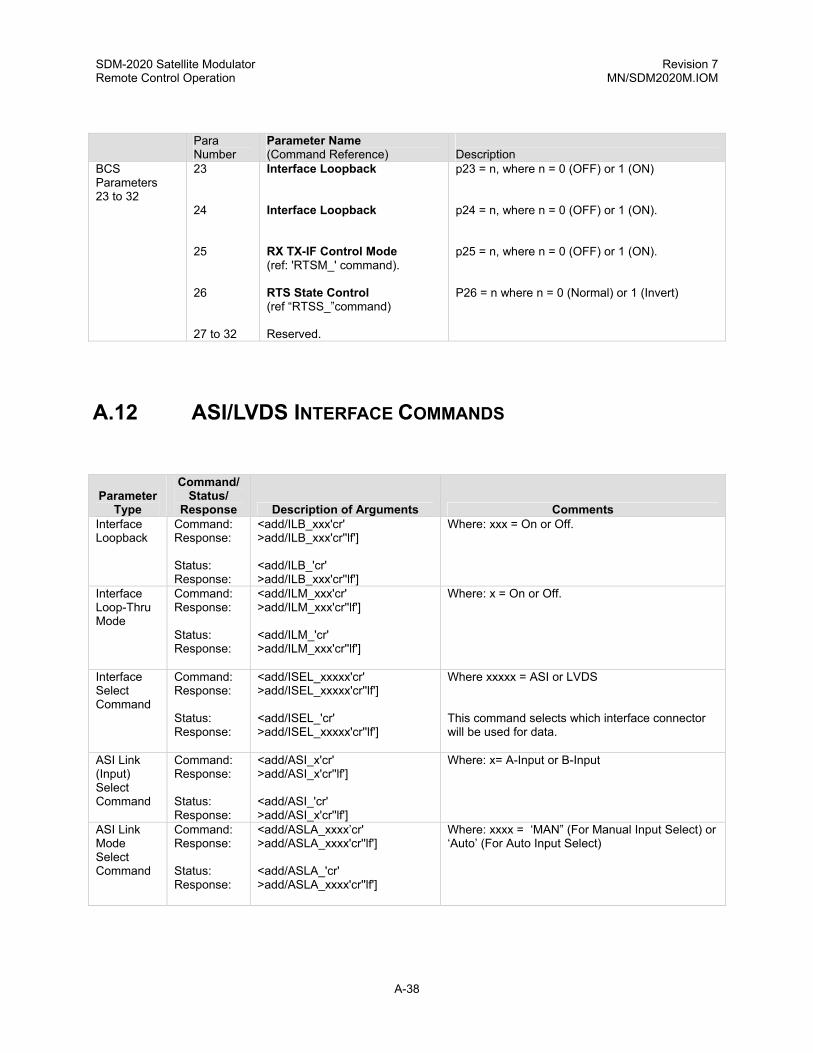
SDM-2020 Satellite Modulator Revision 7 Remote Control Operation MN/SDM2020M.IOM
Para
Number Parameter Name (Command Reference)
Description
BCS Parameters 23 to 32
23 24 25 26 27 to 32
Interface Loopback Interface Loopback RX TX-IF Control Mode (ref: 'RTSM_' command). RTS State Control (ref “RTSS_”command) Reserved.
p23 = n, where n = 0 (OFF) or 1 (ON) p24 = n, where n = 0 (OFF) or 1 (ON). p25 = n, where n = 0 (OFF) or 1 (ON). P26 = n where n = 0 (Normal) or 1 (Invert)
A.12 ASI/LVDS INTERFACE COMMANDS
Parameter Type
Command/ Status/
Response Description of Arguments Comments Interface Loopback
Command: Response: Status: Response:
<add/ILB_xxx'cr' >add/ILB_xxx'cr''lf'] <add/ILB_'cr' >add/ILB_xxx'cr''lf']
Where: xxx = On or Off.
Interface Loop-Thru Mode
Command: Response: Status: Response:
<add/ILM_xxx'cr' >add/ILM_xxx'cr''lf'] <add/ILM_'cr' >add/ILM_xxx'cr''lf']
Where: x = On or Off.
Interface Select Command
Command: Response: Status: Response:
<add/ISEL_xxxxx'cr' >add/ISEL_xxxxx'cr''lf'] <add/ISEL_'cr' >add/ISEL_xxxxx'cr''lf']
Where xxxxx = ASI or LVDS This command selects which interface connector will be used for data.
ASI Link (Input) Select Command
Command: Response: Status: Response:
<add/ASI_x'cr' >add/ASI_x'cr''lf'] <add/ASI_'cr' >add/ASI_x'cr''lf']
Where: x= A-Input or B-Input
ASI Link Mode Select Command
Command: Response: Status: Response:
<add/ASLA_xxxx’cr' >add/ASLA_xxxx'cr''lf'] <add/ASLA_'cr' >add/ASLA_xxxx'cr''lf']
Where: xxxx = ‘MAN” (For Manual Input Select) or ‘Auto’ (For Auto Input Select)
A-38

SDM-2020 Satellite Modulator Revision 7 Remote Control Operation MN/SDM2020M.IOM
ASI Loop Bandwidth Select Command
Command: Response: Status: Response:
<add/ASLB_xxxxxx'cr' >add/ASLB_xxxxxx'cr''lf'] <add/ASLB_'cr' >add/ASLB_xxxxxx'cr''lf']
Where: xxxxxx = Wide or Narrow.
RTS TX-IF Control Mode
Command: Response: Status: Response:
<add/RTSM_xxx'cr' >add/RTSM_xxx'cr''lf'] <add/RTSM_'cr' >add/RTSM_xxx'cr''lf']
Where: xxx = On or Off. This command configures the modem for the RTS TX-IF control mode. If ‘ON’ is selected, the TX-IF output will only be tuned on if the incoming RTS signal is asserted (also the TX-IF output has to be programmed On and No Major modulator faults are presented. If ‘Off” is s elected, the TX-IF output will operate normal ignoring the RTS signal.
RTS State Control
Command: Response: Status: Response:
<add/RTSS_xxx'cr' >add/RTSS_xxx'cr''lf'] <add/RTSS_'cr' >add/RTSS_xxx'cr''lf']
Where: xxx = NRM (normal Sense) ot INV (inverted Sense) This command controls the logic sense of the RTS signal.
Interface Firmware Information
Command: Response:
<add/IFI_'cr' >add/IFI_'cr' FW/nnnnn-drr’cr’ mm/dd/yyyy’cr’’lf’]
Where: nnnnn = Firmware number (0 to 65535) d = Firmware dash number (0 to 99) rr = Firmware revision (-, or A to ZZ)
IJ1 Interface Jumper #1 Setting
Command: Response:
<add/IJ1_'cr' >add/IJ1_xx'cr'’lf’]
Where xx = TX or RX (LVDS)
MCP Command Config.
Command: Response:
<add/MCP_'cr' >add/MCP_'cr' ISEL_xxxxxx'cr' ICLK_xxx'cr' TDVB_xxxx'cr' MF_nnn.nnnn'cr' MR_nnnn_mmm.mmmmmm'cr' MPO_snn.n'cr' MOP_snn.n'cr' SE_xxx'cr' TCP_xxx'cr' TDP_xxxx'cr' TDF_xxxx'cr' ISP_xxx'cr' SYNC_xxxx'cr' MSR_xxx'cr' MT_xxxx'cr' TXPU_xxxxx'cr' COM_xxxxxx'cr' ASI_x'cr' RTSM_xxxx'cr' RTSS_xxxx'cr' TCAA_xxxxx'cr' RF_xxx'cr' ASLB_xxxxxx’cr’ ASIA_xxxx’cr’’lf]
Interface Select Interface Mode DVB Framing Type Modulator Frequency Modulator Rate Modulator Power Offset Modulator Output Power Scrambler Enable (ON/OFF) Transmit Clock Phase Transmit Data Phase Transmit Data Fault Transmit 2047 Pattern Generator Transmit Sync Select Modulator Spectrum Rotation Modulator Type Transmit IF Output Power-up Configuration Carrier Only Mode ASI Input RTS Mode Control RTS State Control TX Clock Activity Action RF Output (ON/OFF) ASI Loop BW (Wide/Narrow) ASI Link Mode (MAN/AUTO)
A-39

SDM-2020 Satellite Modulator Revision 7 Remote Control Operation MN/SDM2020M.IOM
ICS Command Config.
Command: Response:
<add/ICS_'cr' >add/ICS_'cr' TCP_xxx'cr' TDP_xxxx'cr' ISP_xxx'cr' SYNC_xxxx'cr' TDF_xxxx'cr' TDVB_xxxx'cr' INID_xxxxxxxxx'cr' ISEL_xxxxxx'cr' ICLK_xxx'cr' ASI_x'cr' RTSM_xxx'cr' RTSS_xxx'cr' TCAA_xxxxx'cr’ ASLB_xxxxxx’cr’ IJ1_xx’cr’ ASIA_xxxx’’lf’]
Transmit Clock Phase Transmit Data Phase Transmit 2047 Pattern Generator Transmit Sync Select Transmit Data Fault DVB Framing Type Interface Identification Interface Select Interface Mode ASI Input RTS Mode Control RTS State Control TX Clock Activity Action ASI Loop Bandwidth Interface Jumper Position #1 ASI Link Mode (MAN/AUTO)
Para
Number Parameter Name
(Command Reference)
Description BCS Parameters 23 to 32
23 24 25 26 27 28 29 30 31 32
Interface Select (ref. 'ISEL_' command). RTS TX-IF Control Mode (ref. 'RTSM_' command). RTS State Control (ref 'RTSS_' command). ASI Input Control (ref 'ASI_' command). ASI Loop Bandwidth Control (ref 'ASLB_' command). Interface Loopback Interface Loop Thru Interface Jumper #1 ASI Link Mode (ref ‘ASIA_’command) Reserved.
p23 = n, where n = '0' (ASI), '1' (LVDS). p24 = n, where n = '0' (Off), '1' (On). p25 = n, where n = '0' (Normal), '1' (Invert). p26 = n, where n = '0' (A-Input), '1' (B-Input). p27 = n, where n = '0' (Wide), '1' (Narrow). p28 = n, where n = '0' (Off), '1' (On). p29 = n, where n = '0' (Off), '1' (On). p30 = n, where n = ‘0’ RX LVDS), ‘1’ (TX LVDS ) p31 = n, where n = ‘0’ (Manual), ‘1’ (Auto)
A-40
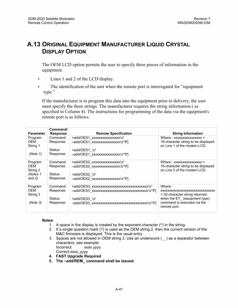
SDM-2020 Satellite Modulator Revision 7 Remote Control Operation MN/SDM2020M.IOM
A.13 ORIGINAL EQUIPMENT MANUFACTURER LIQUID CRYSTAL DISPLAY OPTION
The OEM LCD option permits the user to specify three pieces of information in the equipment.
Lines 1 and 2 of the LCD display.
The identification of the unit when the remote port is interrogated for “equipment type.”
If the manufacturer is to program this data into the equipment prior to delivery, the user must specify the three strings. The manufacturer requires the string information ( as specified in Column 4). The instructions for programming of the data via the equipment's remote port is as follows:
Parameter Command/ Response
Remote Specification
String Information
Program OEM String 1 (Note 1)
Command: Response: Status: Response:
<add/OES1_xxxxxxxxxxxxxxxx'cr' >add/OES1_xxxxxxxxxxxxxxxx'cr''If'] <add/OES1_'cr' >add/OES1_xxxxxxxxxxxxxxxx'cr''If']
Where : xxxxxxxxxxxxxxxx = 16-character string to be displayed on Line 1 of the modem LCD.
Program OEM String 2 (Notes 1 and 2)
Command: Response: Status: Response:
<add/OES2_xxxxxxxxxxxxxxxx'cr' >add/OES2_xxxxxxxxxxxxxxxx'cr''If'] <add/OES2_'cr' >add/OES2_xxxxxxxxxxxxxxxx'cr''If']
Where : xxxxxxxxxxxxxxxx = 16-character string to be displayed on Line 2 of the modem LCD.
Program OEM String 3 (Note 3)
Command: Response: Status: Response:
<add/OES3_xxxxxxxxxxxxxxxxxxxxxxxxxxxxxxxx'cr' >add/OES3_xxxxxxxxxxxxxxxxxxxxxxxxxxxxxxxx'cr''lf'] <add/OES3_'cr' >add/OES3_xxxxxxxxxxxxxxxxxxxxxxxxxxxxxxxx'cr''If']
Where : xxxxxxxxxxxxxxxxxxxxxxxxxxxxxxx = 32-character string returned when the ET_ (equipment type) command is executed via the remote port.
Notes:
1. A space in the display is created by the exponent character (^) in the string. 2. If a single question mark (?) is used as the OEM string 2, then the current version of the
M&C firmware is displayed. This is the usual entry. 3. Spaces are not allowed in OEM string 3. Use an underscore ( _ ) as a separator between
characters, see example: Incorrect: xxxx yyyy Correct: xxxx_yyyy
4. FAST Upgrade Required 5. The <add/REM_ command shall be issued.
A-41

SDM-2020 Satellite Modulator Revision 7 Remote Control Operation MN/SDM2020M.IOM
This page is intentionally left blank.
A-42

Errata A Comtech EF Data Documentation Update
Subject: Changes to Table 2-1. General Specification Date: July 11, 2003 Document: SDM-2020 Satellite Modulator Installation and Operation Manual,
Rev. 7, dated June 30, 2002 Part Number: MN/SDM2020M.EA7 Collating Instructions: Attach this page to page 2-1 Comments:
The following changes provide updated information for Table 2-1. This information will be incorporated into the next revision.
Change Specifics:
Table 2-1. General Specifications
Parameter Specification Spectral Shaping DVB-1, square-root raised cosine, α = 0.35 per EN 300 421
and prEN 301 210 DVB-2, narrower than DVB-1. Substantically meets DVB 25% rolloff but not fully compliant. 99% BW, 99% of the transmitted energy is contained within a bandwidth ≤ 1.2 x (Symbol Rate).
s:\tpubs\manuals\released_word\modems\sdm2020m_rev7\errata a.doc 1

Errata B Comtech EF Data Documentation Update
Subject: Changes to Table 2-4. Modulator Specifications Date: July 11, 2003 Document: SDM-2020 Satellite Modulator Installation and Operation Manual,
Rev. 7, dated June 30, 2002 Part Number: MN/SDM2020M.EB7 Collating Instructions: Attach this page to page 2-5 Comments:
The following changes provide updated information for Table 2-4. This information will be incorporated into the next revision.
Change Specifics:
Table 2-4. Modulator Specifications (Continued)
Moniotr & Control Characteristics Modulation, Coding Modulation Type: QPSK, 8PSK, 16QAM
Code Rate (Viterbi/Trellis) Spectral Inversion, DVB-1, DVB-2, 99% BW
s:\tpubs\manuals\released_word\modems\sdm2020m_rev7\errata b.doc 1

Errata C Comtech EF Data Documentation Update
Subject: Changes to 5.6.7.4 Utility: Modulator: Modulator Type Date: July 11, 2003 Document: SDM-2020 Satellite Modulator Installation and Operation Manual,
Rev. 7, dated June 30, 2002 Part Number: MN/SDM2020M.EC7 Collating Instructions: Attach this page to page 5-26 Comments:
The following changes provide updated information for Paragraph 5.6.7.4. This information will be incorporated into the next revision.
Change Specifics: 5.6.7.4. UTILITY: MODULATOR: MODULATOR TYPE
MODULATOR TYPE
DVB-1
Use this menu to select a spectral mask type of DVB-1, DVB-2, or DVB-99:
DVB-1 This is the default mask and is the “Best Fit” to the ETS 300 421 mask. DVB-2 This mask has a sharper cutoff in the transition region from 3 to 40 dB
resulting in a narrower spectral, than DVB-1, at the 35 dB down region. 99% BW 99% of the transmitted energy is contained within a bandwidth ≤ 1.2 x
(Symbol Rate).
1. While in this menu, press <ENTER> to turn OFF the TX-IF Output. 2. Press <ENTER> a second time to turn ON the TX-IF OUTPUT.
s:\tpubs\manuals\released_word\modems\sdm2020m_rev7\errata c.doc 1

Errata D Comtech EF Data Documentation Update
Subject: Changes to BMC Remote Commands Date: July 11, 2003 Document: SDM-2020 Satellite Modulator Installation and Operation Manual,
Rev. 7, dated June 30, 2002 Part Number: MN/SDM2020M.ED7 Collating Instructions: Attach this page to page A-8 Comments:
The following changes provide updated information for BMC Parameters. This information will be incorporated into the next revision.
Change Specifics: BMC Parameters 1 to 33
Parameter Number
Parameter Name (Command Reference)
Description
9 Modulator Type (ref. ‘MT_’command)
p9 = n, where ‘n’ is ‘0’, ‘1’, or ‘2’ (0=DVB-1, 1=DVB-2, or 2=DVB-99)
s:\tpubs\manuals\released_word\modems\sdm2020m_rev7\errata d.doc 1

Errata E Comtech EF Data Documentation Update
Subject: Changes to BCS Remote Commands Date: July 11, 2003 Document: SDM-2020 Satellite Modulator Installation and Operation Manual,
Rev. 7, dated June 30, 2002 Part Number: MN/SDM2020M.EE7 Collating Instructions: Attach this page to page A-21 Comments:
The following changes provide updated information for BCS Parameters. This information will be incorporated into the next revision.
Change Specifics: BCS Parameters 1 to 33
Parameter Number
Parameter Name (Command Reference)
Description
11 Modulator Type (ref. ‘MT_’command)
p11 = n, where ‘n’ is ‘0’, ‘1’, or ‘2’ (0=DVB-1, 1=DVB-2, or 2=DVB-99)
s:\tpubs\manuals\released_word\modems\sdm2020m_rev7\errata e.doc 1
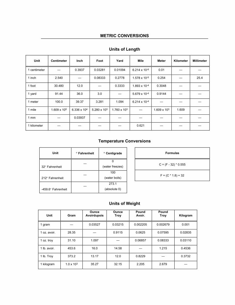
METRIC CONVERSIONS
Units of Length
Unit
Centimeter
Inch
Foot
Yard
Mile
Meter
Kilometer
Millimeter
1 centimeter — 0.3937 0.03281 0.01094 6.214 x 10⁻⁶ 0.01 — —
1 inch 2.540 — 0.08333 0.2778 1.578 x 10⁻⁵ 0.254 — 25.4
1 foot 30.480 12.0 — 0.3333 1.893 x 10⁻⁴ 0.3048 — —
1 yard 91.44 36.0 3.0 — 5.679 x 10⁻⁴ 0.9144 — —
1 meter 100.0 39.37 3.281 1.094 6.214 x 10⁻⁴ — — —
1 mile 1.609 x 10⁵ 6.336 x 10⁴ 5.280 x 10³ 1.760 x 10³ — 1.609 x 10³ 1.609 —
1 mm — 0.03937 — — — — — —
1 kilometer — — — — 0.621 — — —
Temperature Conversions
Units of Weight
Unit
Gram
Ounce Avoirdupois
Ounce Troy
Pound Avoir.
Pound Troy
Kilogram
1 gram — 0.03527 0.03215 0.002205 0.002679 0.001
1 oz. avoir. 28.35 — 0.9115 0.0625 0.07595 0.02835
1 oz. troy 31.10 1.097 — 0.06857 0.08333 0.03110
1 lb. avoir. 453.6 16.0 14.58 — 1.215 0.4536
1 lb. Troy 373.2 13.17 12.0 0.8229 — 0.3732
1 kilogram 1.0 x 10³ 35.27 32.15 2.205 2.679 —
Unit
° Fahrenheit
° Centigrade
32° Fahrenheit —
0
(water freezes)
212° Fahrenheit —
100
(water boils)
-459.6° Fahrenheit —
273.1
(absolute 0)
Formulas
C = (F - 32) * 0.555
F = (C * 1.8) + 32

2114 WEST 7TH STREET TEMPE ARIZONA 85281 USA 480 • 333 • 2200 PHONE
480 • 333 • 2161 FAX