Embed Size (px)
Citation preview

1
SD Express (SD7.x)Host Implementation Guideline
Design Guide | May 2020
SD Express (SD7.x) Host Implementation Guideline
www.sdcard.org | ©2020 SD Association. All rights reserved

Conditions for publication
Publisher and Copyright Holder:
SD Card Association5000 Executive Parkway, Suite 302San Ramon, CA 94583 USATelephone: +1 (925) 275-6615Fax: +1 (925) 886-4870E-mail: [email protected]
Disclaimers:
The information contained in this whitepaper is provided as is without any representations or warranties of any kind. No responsibility is assumed by the SD Association for any damages, or any infringements of patents or other rights of the SD Association or any third-parties, which may result from the use of any portion thereof. No license is granted by implication, estoppel or otherwise under any patent or other rights of the SD Association or any third-party. Nothing herein shall be construed as an obligation by the SD Association to disclose or distribute any technical information, know-how or other confidential information to any third party.
Specifications are subject to change without notice. Nonmetric weights and measurements are approximate. All data were deemed correct a time of creation. SD Association is not liable for errors or omissions. All brand, product, service names and logos are trademarks and/or registered trademarks of their respective owners and are hereby recognized and acknowledged.
Trademarks Notice:
SD and related marks and logos are trademarks of SD-3C LLC.
© 2019-2020 SD-3C LLC. All Rights Reserved.
Linux® is registered trademark of Linus Torvalds.
eMMC, UFS and UFS Card specifications originated by JEDEC
SATA (Serial ATA) is a specification originated by Serial ATA International Organization (SATA-IO) which is owned today and driven by INCITS T13 and T10 (SCSI)
PCI Express® is a registered trademark of PCI-SIG®.
NVM ExpressTM and NVMeTM are trademarks of NVM Express, Inc.
2SD Express (SD7.x) Host Implementation Guideline
www.sdcard.org | ©2020 SD Association. All rights reserved

3
Table of Contents1. Purpose And Scope . . . . . . . . . . . . . . . . . . . . . . . . . . . . . . . . . . . . . . . . . . . . . . . . . . . . . . . . . . . . . . . . . . . . . . . . . 42. SD Express Card – Description. . . . . . . . . . . . . . . . . . . . . . . . . . . . . . . . . . . . . . . . . . . . . . . . . . . . . . . . . . . . . . . 53. SD Host Types That May Accept SD Express Card. . . . . . . . . . . . . . . . . . . . . . . . . . . . . . . . . . . . . . . . . . . . 64. Hardware. . . . . . . . . . . . . . . . . . . . . . . . . . . . . . . . . . . . . . . . . . . . . . . . . . . . . . . . . . . . . . . . . . . . . . . . . . . . . . . . . . . . 95. SW Drivers . . . . . . . . . . . . . . . . . . . . . . . . . . . . . . . . . . . . . . . . . . . . . . . . . . . . . . . . . . . . . . . . . . . . . . . . . . . . . . . . . 136. Power and Thermal Management. . . . . . . . . . . . . . . . . . . . . . . . . . . . . . . . . . . . . . . . . . . . . . . . . . . . . . . . . . 177. SD Express and microSD Express Test Fixtures . . . . . . . . . . . . . . . . . . . . . . . . . . . . . . . . . . . . . . . . . . . . . 18Appendix A: Common Thermal Conducting Solutions. . . . . . . . . . . . . . . . . . . . . . . . . . . . . . . . . . . . . . . . 19Appendix B: Off-The-Shelf SD Express Host Solution. . . . . . . . . . . . . . . . . . . . . . . . . . . . . . . . . . . . . . . . . . 21Figure 1 microSD Express and full size SD Express cards . . . . . . . . . . . . . . . . . . . . . . . . . . . . . . . . . . . . . . . 4Figure 2 SD Express Card Block Diagram. . . . . . . . . . . . . . . . . . . . . . . . . . . . . . . . . . . . . . . . . . . . . . . . . . . . . . . 5Figure 3 SD Express Host = SD and PCIe . . . . . . . . . . . . . . . . . . . . . . . . . . . . . . . . . . . . . . . . . . . . . . . . . . . . . . . 6Figure 4 SD Host. . . . . . . . . . . . . . . . . . . . . . . . . . . . . . . . . . . . . . . . . . . . . . . . . . . . . . . . . . . . . . . . . . . . . . . . . . . . . . . 6Figure 5 M.2/PCIe to SD7.x Adapter. . . . . . . . . . . . . . . . . . . . . . . . . . . . . . . . . . . . . . . . . . . . . . . . . . . . . . . . . . . . 8Figure 6 SD Express Host – Block Diagram . . . . . . . . . . . . . . . . . . . . . . . . . . . . . . . . . . . . . . . . . . . . . . . . . . . . 9Figure 7 Block Diagram of SD Express Host with new Control lines. . . . . . . . . . . . . . . . . . . . . . . . . . . 10Figure 8 A Practical Example of Mux/De-Mux circuit. . . . . . . . . . . . . . . . . . . . . . . . . . . . . . . . . . . . . . . . . . 10Figure 9 SD Host Controller Register Map with added SD Express Support . . . . . . . . . . . . . . . . . . . 11Figure 10 Flow Chart of Initialization process starts from PCIe drivers first . . . . . . . . . . . . . . . . . . . . 13Figure 11 Flow Chart of Initialization process starts from SD drivers first . . . . . . . . . . . . . . . . . . . . . . 13Figure 12 SD Express – Android Host Driver Layers Overview . . . . . . . . . . . . . . . . . . . . . . . . . . . . . . . . 14Figure 13 Flow Chart of the updated SD Drivers Operation during Initialization . . . . . . . . . . . . . . 16Figure 14 microSD Card and Host test adapters . . . . . . . . . . . . . . . . . . . . . . . . . . . . . . . . . . . . . . . . . . . . . . 18Figure 15 microSD Express Test Adapter installed on standard CBB as PCIe add-in card . . . . . . 18Figure 16 microSD Express and SD Express Host Test Adapters may be inserted to related SD Express hosts . . . . . . . . . . . . . . . . . . . . . . . . . . . . . . . . . . . . . . . . . . . . . . . . . . . . . . . . . . . . . . . . . . . . . 18Figure 17 Recommended PCB high level design concepts. . . . . . . . . . . . . . . . . . . . . . . . . . . . . . . . . . . . 19Figure 18 Heat Pipe. . . . . . . . . . . . . . . . . . . . . . . . . . . . . . . . . . . . . . . . . . . . . . . . . . . . . . . . . . . . . . . . . . . . . . . . . . . 19Figure 19 Graphene Tape. . . . . . . . . . . . . . . . . . . . . . . . . . . . . . . . . . . . . . . . . . . . . . . . . . . . . . . . . . . . . . . . . . . . . 20
Table of TablesTable 1 Voltage Ranges and Max Currents Allowed in SD Express card at PCIe mode . . . . . . . . . 12Table 2 NVMe Drivers. . . . . . . . . . . . . . . . . . . . . . . . . . . . . . . . . . . . . . . . . . . . . . . . . . . . . . . . . . . . . . . . . . . . . . . . . 14Table 3 Existing SD Drivers . . . . . . . . . . . . . . . . . . . . . . . . . . . . . . . . . . . . . . . . . . . . . . . . . . . . . . . . . . . . . . . . . . . 15Table 4 Pros and Cons of Initialization options: SD-First or PCIe-First. . . . . . . . . . . . . . . . . . . . . . . . . . 15Table 5 PCIe Power Substates. . . . . . . . . . . . . . . . . . . . . . . . . . . . . . . . . . . . . . . . . . . . . . . . . . . . . . . . . . . . . . . . . 17 Table 6 Card’s Maximum Card Case Temperature (Tc) allowed at each Power State . . . . . . . . . . 17
SD Express (SD7.x) Host Implementation Guideline
www.sdcard.org | ©2020 SD Association. All rights reserved

The SD Association (SDA) introduced SD Express via the SD7.0 and microSD SD7.1 specifications in anticipation of new market demands for high performance applications such as mobile computing, gaming and Internet of Things (IoT) as well as opening new opportunities for removable memory cards usage. SD Express integrates PCIe/NVMe interface to the legacy SD interface for SD and microSD memory cards while maintaining full backward compatibility.
The SDA prepared this document to provide recommendations on how to implement SD Express into host products to maximize the specification’s capabilities of the new PCIe/NVMe interface and maintain backwards compatibility.
Figure 1 microSD Express and full size SD Express cards
1.1 Referenced Documents
1.1.1 SDA Specifications:• Part 1 Physical Layer Specification Ver 7.0 (SD Express
full size introduced) referred hereafter as SD7.0 and its Standard Size Mechanical Addendum Ver7.0.
• Part 1 Physical Layer Specification Ver 7.1 (microSD Express added) referred hereafter as SD7.1 and the microSD Card Addendum Ver 7.0. Note: When SD7.x specification is mentioned, it relates to both SD7.0 and SD7.1.
• Part A2 Standard Host Controller Ver 6.0 – Referred also as SHC. Note that SHC Ver 7 that will include SD Express interface is under release process and is expected to be available by mid-2020.
Note that only SDA members and host or card licensees may get an access to the official SDA specifications. In order to become a member – please refer to this link.
Also, the SDA published a simplified version of the above mentioned specifications that non-members may download for general study usage or drivers development. The simplified specifications are not intended for product (card or host) developments. Physical layer Simplified Specification Ver 7.1 can be downloaded from the following link.
1.1.2 PCI-SIG Specifications• PCI Express Base Specification Revision 3.1a
PCI-SIG specifications may be downloaded from PCI-SIG site through this link.
4
1. Purpose And Scope
SD Express (SD7.x) Host Implementation Guideline
www.sdcard.org | ©2020 SD Association. All rights reserved

5SD Express (SD7.x) Host Implementation Guideline
www.sdcard.org | ©2020 SD Association. All rights reserved
SD Express and microSD Express memory cards are based on SD Physical spec version 7.0 and 7.1, respectively. For simplicity sake, we will refer to them both as SD Express hereafter. Both have the same general block diagram, as shown in Figure 2.
To simplify the concept, an SD Express card can be considered a traditional UHS-I memory card with the PCIe interface and NVMe protocol.
The physical interface:• The PCIe physical interface is as defined by PCI-SIG:
PCIe 3.1 specification, single lane.• The SD Express adopted the PCIe 3.1 spec using the
following side band signals: PERST# and CLKREQ#. • Power Supply of VDD2 = 1.8v (in addition to
VDD1=3.3v) is mandatory for the PCIe interface to operate.
• Due to the limitation of space, the two side band signals and the REFCLK+/- signals are muxed with the SD DATA lines.
The functional interface:• In PCIe mode of operation, the card introduces itself
to the host as a standard “NVM Express Device” (PCIe Class ID: 01h->08h->02h; as shown in PCI Code ID spec). This is the same as other NVMe devices like SSD or M.2 devices, so standard PCI/NVMe drivers can be used to access the card in PCIe mode.
• SD Express card may be initialized either through the SD interface or through the PCIe interface. The card may automatically recognize the PCIe mode of operation upon VDD2 supply from the host.
• If a host operates in PCIe mode, it may either:A. SD-First: Initialize the SD Express card through SD
interface first after power up of VDD1, check if card supports PCIe, if it support PCIe it will switch to PCIe mode by supplying VDD2.
B. PCIe-First: Access the card directly in PCIe mode right after power up of VDD1 followed by VDD2.
• Starting with SD interface initialization is recommended because it allows faster initialization if a legacy SD memory card is inserted. It is also the most straightforward implementation without changing PCIe or NVMe drivers and has minimal effect on the overall initialization time versus initializing through PCIe interface (as further explained in section 5.4 below).
Bottom line: Implementation of SD Express host is simple, because:
1. Existing PCIe interface may be used as is and existing SD interface with minimal addition may be used.
2. A relatively simple hardware mux/de-mux unit needs to be added at the front end allowing the separation of the PCIe side band and REFCLK+/- signals from the SD DAT lines. There are readily available off-the-shelf dedicated units designed to perform mux/de-mux in the market today, making implementation easy.
2. SD Express Card – DescriptionBi
-dire
ctio
nal
Mux
/De-
Mux
SD Host Interface Module
PCIe/NVMe Interface
Mem
ory
man
agem
ent
1.8v SD/PCIe Mode indication
SD_DAT0SD_DAT1SD_DAT2SD_DAT3
SD_CMDSD_CLK
PCIe_REFCLK_P
PCIe_REFCLK_N
PCIe_PERST#PCIe_CLKREQ#
SD_DAT0/PCIe_REFCLK_P
SD_DAT1/PCIe_REFCLK_NSD_DAT2/PCIe_CLKREQ#
SD_DAT3/PCIe_PERST#
SD Express Card Block Diagram
PCIe_RX_PPCIe_RX_N
PCIe_TX_NPCIe_TX_P
PCIe_TX+PCIe_TX-
PCIe_RX+PCIe_RX-
VDD2
CLKCMD
DAT3DAT2DAT1DAT0
PCIe/SD Mode
Mem
ory
devi
ce
CPUVDD1 3.3v
Figure 2 SD Express Card Block Diagram

6SD Express (SD7.x) Host Implementation Guideline
www.sdcard.org | ©2020 SD Association. All rights reserved
3. As for software drivers, existing PCIe/NVMe drivers may be used. The only addition needed is the switching mechanism between SD drivers to PCIe and the control of VDD2 supply for PCIe mode of operation that may be used also as the SD/PCIe mode selection for the front end mux circuit. The SD drivers will require an update to support the new interface. That update is expected to be contributed to the open source community (see the drivers section below).
4. Host vendors interested in implementing SD Express into host devices without having SD Express cards may complete major portions of design verification processes by using SD Express demonstration cards available from some card manufacturers. They can use the existing PCIe interface for their PCIe interface mode tests along with legacy SD cards for their SD mode tests. To complete host device electrical tests of the PCIe interface the existing SD Express Card Load Boards that are available from SDA for the PCIe host electrical testing may be used (as described in chapter 7). These tests may serve as preliminary host tests and may complete a large amount of verification work until SD Express cards are released in the marketplace. Additional details are provided in the following sections.
3. SD Host Types That May Accept SD Express Card
Any of the following hosts can use SD Express cards:
1. Host supporting both SD and PCIe interface (Figure 3): • Host and card can use either SD or PCIe interface operating the
SD Express card in either SD mode or PCIe mode.
2. Host supporting only SD interface (Figure 4): • Host and card will use SD pins operating the SD Express card in
SD mode.
3. Host supporting only PCIe interface:This type of implementation is not backward compatible to legacy SD cards that use only the SD interface for access. Therefore, SDA is
not recommending implementation of such hosts, even though SD Express cards use a standard PCIe/NVMe interface and it may be initialized through its PCIe interface. It can operate in such host by operating the SD Express card in PCIe mode only. Such operation option is possible to be used during development process and such option is described in section 3.2.
SD Express Host(SD+PCIe support)
May operate in either SD or PCIe SD Express Card
May operate in SD mode only SD Express CardSD Host
SD Express Host(SD+PCIe support)
May operate in either SD or PCIe SD Express Card
May operate in SD mode only SD Express CardSD Host
Figure 3 SD Express Card Block Diagram
Figure 4 SD Host

7
3.1 SD Express Host3.1.1 Pin out
• SD 7.0: Refer to Table 3.7.3-1 of SD7.0 Specification.• microSD 7.1: Refer to Figure 2-4, and Table 2-5 of
microSD Card Addendum Version 7.10 Specification.
3.1.2 Recommended FeaturesRefer to Section 8.1.3 to 8.1.6 of SD7.0 Specification for SD 7.x card supported, optional, not supported, and partially supported features. SD 7.x Host is highly recommended to support at least all mandatory SD 7.x card supported features (Section 8.1.3 in SD7.0) on host side.
When designing an SD Express host device, consider the following recommendations to best utilize SD Express card capabilities.
SD Mode:• Allow maximum power in default speed mode of SDXC
and SDUC cards by setting power control bit in ACM41, XPC, to 1 as this is the maximum performance mode.
• Send Power off notification to the card before turning OFF the power to the card during idle time.
PCIe Mode:• The SD Express PCIe interface uses CLKREQ# and
PERST# sideband signals only. The initialization process/conditions should conform to the PCIe and SD Express standard.
• Support Single Lane (x1).• Support hot pluggable feature.• Host should allow SD Express card to work in full
swing operation mode (800mV) even though PCIe allows full swing operation and half swing operation.
• Host should support the latest available NVMe 1.3+ (e.g., 1.3d at the publication of this document) to assure full backward compatibility and interoperability to all cards in the market.
• Support 1 namespace.• L1.1 and L1.2 power sub-states to be supported in
PCIe for power saving during standby.
• Host may manage power and thermal conditions using card’s three power states: 0.72W, 1.44W and 1.8W (default) through the NVMe protocol.
3.1.3 Interface Detection and Initialization sequenceRefer to Section 3.17.2 in SD7.x for the initialization sequence shown from host and card sides that covers all the cases. A more detailed description of each specific case along with signal diagrams can be found in Section 8.3.2 of SD7.x.
3.1 SD Host
Any legacy SD host in the market may support the operation of an SD Express card. In such a host, the SD interface of the SD Express card will be used as guaranteed by the specification. Speeds of SDR50 and DDR50 for microSD Express will be supported while DDR50 in full size cards and SDR104 may also be supported if implemented by the cards.Refer to section 3.17.2 in SD7.0 Specification for the SD Express card internal state diagram. Initializing the card with legacy SD host will move the card to its SD mode of operation at the moment that SD CLK will be provided by the host.
3.2 PCIe Host3.2.1 Interface Selection and Pinout
• As mentioned earlier – SDA is not recommending implementation of PCIe host that does not support SD, as this host will not be backward compatible to existing legacy SD cards.
• There is no issue to operate SD Express cards in PCIe host because it supports initialization directly through the PCIe interface. Therefore, it can be used in such ways for non-retail usage and for the development process.
• A standard PCIe 3 interface may be used on host side with the following considerations:- Side band signals used with SD Express card are
PERST# and CLKREQ#. - Card Present Detect (PRSNT#) input shall be
supported (as should be provided by any PCIe interfaces supporting hot plug in/out).
SD Express (SD7.x) Host Implementation Guideline
www.sdcard.org | ©2020 SD Association. All rights reserved

8
- In order for SD Express card to operate in PCIe mode, it needs VDD1 (3.3v) and VDD2. (1.8v) power sources to be supplied plus VDD2 must be supplied to the SD Express card after VDD1 is set to ON.
- SD Express card does not have internal AC coupling capacitors on its PCIe output lines. The two AC caps (176nF to 265nF as defined in PCIe standard) need to be added on host within a distance of up to 12.5mm from the SD connector’s PCIe RX lane contacts. Those caps are in addition to the AC coupling caps already connected at the TX lane of the PCIe lines of the host side.
• Refer to Section 3.7.3 and Table 3.7.3-1 of SD 7.0 Specification for SD form factor pin out.
• Refer to Section 2.4 and Table 2-5 of microSD Card Addendum Ver 7.1 Specification for microSD pin out.
3.2.2 M.2/PCIe to SD 7.x Card Adapter A practical example of PCIe Host usage for test and/or development of PCIe interface of SD Express card may be done through a M.2/PCIe Card to SD Express card adapter. Such a solution may allow operation of SD Express card in existing host that includes PCIe card or M.2 card slot. Figure 5 shows an example of an adapter card.
Figure 5 M.2/PCIe to SD7.x Adapter
Note that the 1.8V can be derived from 3.3V on the adapter board using DC-DC converter as shown above (optional). The 1.8V supply
must be delivered to the card after the 3.3V supply is on.
3.2.3 Interface Detection and Initialization SequenceRefer to section 3.17.2 in the SD7.0 specification for the initialization sequence shown from host and card sides that covers all the cases. Use the PCIe direct path, not through SD interface first. For the configuration shown in Figure 5, host may use the existing standard PCIe/NVMe initialization process and drivers. The card, as mentioned, will conform to PCIe specification and introduce itself as standard NVMe memory device.
3.2.4 Recommended Features• SD Express host initialization process and conditions
should conform to the PCIe specification.• The host should support up to PCIe 3.1 with up to 985
MB/s and CLKREQ# + PERST# side band signals.• Support Single Lane (x1).• Support hot pluggable feature.• SD Express host should allow SD Express card to work
in full swing operation mode (800mV).• Host should support the latest available NVMe 1.3+
(e.g., 1.3d at the publication of this document) to assure full backward compatibility and interoperability to all cards in the market.
• Support 1 namespace.• L1.1 and L1.2 power sub-states to be supported in PCIe
for power saving during standby.• Host may manage power and thermal conditions using
card’s three power states: 0.72W, 1.44W and 1.8W (default) through the NVMe protocol.
Note: SD Express host is not required to recognize that the inserted card is an SD Express type of card. As mentioned, the card appears as standard NVM Express device. However, in cases where the host is aware of the existence of SD, and it wants to read some of the unique SD registers information, it may access it through some of the NVMe registers. For further information, refer to Section 8.1.7 of SD7.0 Specification for register mapping SD → NVMe/ PCIe.
SD Express (SD7.x) Host Implementation Guideline
www.sdcard.org | ©2020 SD Association. All rights reserved
DC-DCConverter
SD/uSD Express Socket
3.3V 1.8V
PCIe RX_lane_P/N
PCIe TX_lane_P/NPREST#, CLKREQ#PCIe_REF_CLK_100MHz
M.2
or P
CIe
slot
AC caps
22uF
47uF
9SD Express (SD7.x) Host Implementation Guideline
www.sdcard.org | ©2020 SD Association. All rights reserved
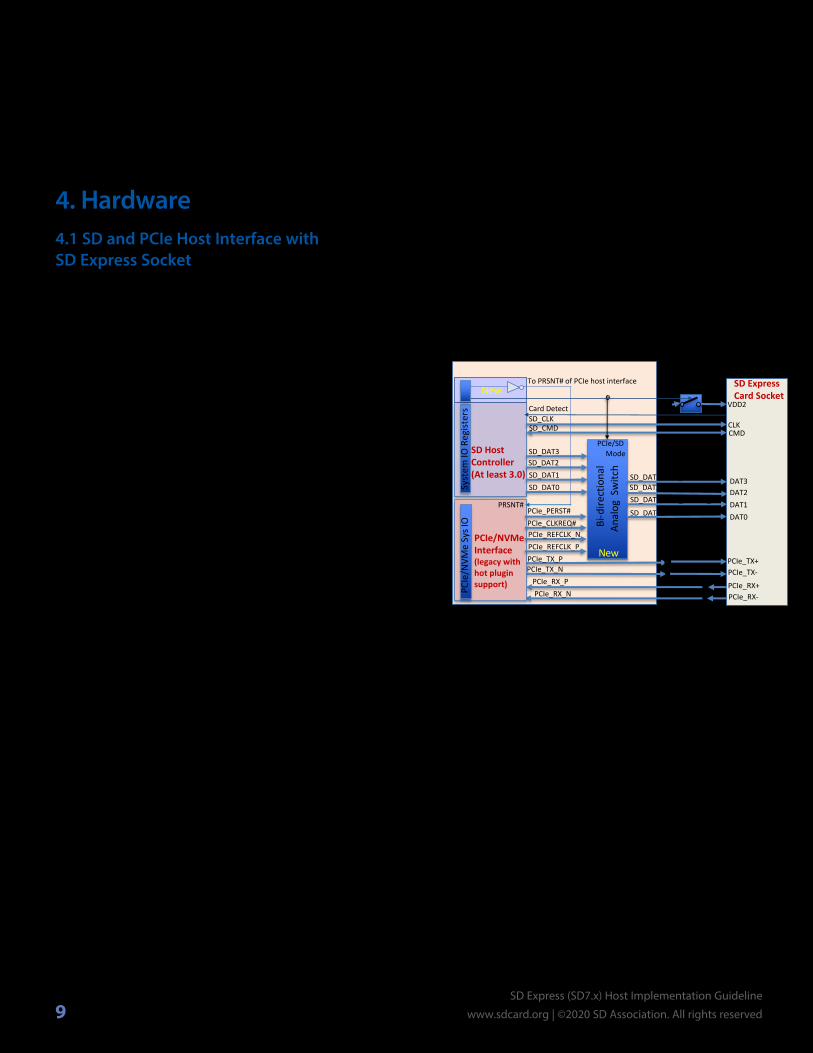
4. Hardware 4.1 SD and PCIe Host Interface with SD Express Socket
This section provides an overview of how a host may utilize an existing SD host controller and existing PCIe interface to implement the interface necessary to support SD Express cards.
The PCIe interface used in SD Express card includes the following three signal groups:
• Differential interfaces- PCIe_TX_P and PCIe_TX_N – Inputs to the card- PCIe_RX_P and PCIe_RX_N – Outputs from the card
• Differential CLK Interface- PCIe_REFCLK_P and PCIe_REFCLK_N – Inputs
to the card These lines are muxed in the card with DAT0
and DAT1 of the SD interface• Sideband Signals
- PERST# – logic output from host to the card, muxed in the card with DAT3 of the SD interface
- CLKREQ# – Open drain I/O for both card and host with pullup on host side, muxed in the card with DAT2 of the SD interface
In addition, there is a VDD2 (1.8v) supply to the card that is required only for the PCIe mode. A possible solution is to use an existing PCIe host module and existing PCIe/NVMe drivers along with minimum changes in the SD host controller with an added analog switch for the front end, is recommended by SDA and described in the next paragraph. Note that there are other solutions allowing use of existing circuitry of PCIe interface from different vendors available in the marketplace today. An example of such off-the-shelf solution is provided in Appendix B.
The SD Express interface was defined in a way that existing PCIe IP (supporting hot plugin) and SD host controller V3 may be used to implement the SD Express interface with minimal additions. The only challenge on the host side
would be the handling of the switched signals. There are various ways to implement such switching considering the nature of the combined signals, especially if it is implemented within a SoC. In this document a straight forward example of Bi-Directional Analog Switch is shown. Any type of solution that meets the SD Express interface requirements is correct.
Figure 6 SD Express Host – Block Diagram
The block diagram example of an SD Express host in Figure 6 shows a case in which host vendor, or chip-set vendor, utilizes the existing PCIe host IP that supports hot plugin with card presence detect PRSNT# input and SD Host Controller with at least SD Host Controller (SHC) V3 specification interface with minimal addition of two new control registers to implement a unified SD Express card interface.
The Bi-Directional Analog Switch shown is a functional representation of various possible practical solutions that may be implemented. Its functionality is to do the switching between SD_DAT(3:0) lines and the side band signals + PCIe REFCLK, allowing a single functionality, at a single time, towards the SD Express card – either as PCIe or as SD. It is assumed that the PCIe/SD functionality is selected through a control line.
Bi-d
irect
iona
l An
alog
Sw
itch
Syst
em IO
Reg
ister
sSD Host Controller (At least 3.0)
PCIe/NVMe Interface (legacy with hot plugin support)PC
Ie/N
VMe
Sys I
O
1.8v
VDD2_ON
SD_DAT0SD_DAT1SD_DAT2SD_DAT3
SD_CMDSD_CLK
PCIe_REFCLK_PPCIe_REFCLK_N
PCIe_PERST#PCIe_CLKREQ#
SD_DAT0/PCIe_REFCLK_P
SD_DAT1/PCIe_REFCLK_NSD_DAT2/PCIe_CLKREQ#SD_DAT3/PCIe_PERST#
SD Express Card Socket
PCIe_TX_PPCIe_TX_N
PCIe_RX_NPCIe_RX_P
PCIe_TX+PCIe_TX-
PCIe_RX+PCIe_RX-
VDD2
CLKCMD
DAT3DAT2DAT1DAT0
PCIe/SD Mode
VDD2_ON
PCIe/NVMe_Interface_Enable To PRSNT# of PCIe host interface
Card Detect
New
New
PRSNT#

10SD Express (SD7.x) Host Implementation Guideline
www.sdcard.org | ©2020 SD Association. All rights reserved
The VDD2 line supplied to the SD Express only for PCIe operation mode may be used to switch the Analog Switch to PCIe mode. Note that the PCIe/SD Mode control signal, used for the Switch, and VDD2 may be implemented as separate control lines; however, it may be simplified if VDD2 is used for the front end PCIe/SD mode selection (see example as well as the initialization flow charts shown in Chapter 5).
The Card Detection Mechanism in Figure 6 shows an existing SD socket card detect switch connected to an existing SHC and the card presence detect of the PCIe interface (PRSNT#) is connected to the output of the new SHC register (controlled by a new PCIe/NVMe_Interface_Enable bit), allowing over all control of the drivers operations through the SD drivers. Detailed description of new control bits of registers (VDD2_ON, PCIe/NVMe_Interface_Enable and PCIe/NVMe support) is provided in section 4.1.1 below.
Figure 7 describes the SD Express Host connections with emphasis on the new control lines and ability to perform the switching between SD and PCIe modes with their associated drivers usage. A detailed flow chart of the updated SD drivers that can support the given example is shown in Section 5.4.
Figure 7 Block Diagram of SD Express Host with new Control lines
Figure 8 shows a straightforward example of usage of external discrete component serving as Bi-Directional Analog Switch. Any type of solution that will meet the SD Express interface requirements is acceptable.
Figure 8 A Practical Example of Mux/De-Mux circuit
The following are a few hardware considerations when implementing the above example:
• Parasitic capacitance of multiplexer device should be considered while selecting the multiplexer device and designer should make sure the design meets the SI requirements like jitter, insertion loss etc. for SD/PCIe interface as per SD Express specification.
• To support hot insertion of SD Express cards, host product design should provide enough capacitance on host board on both VDD1 and VDD2 power rails to reduce influence of voltage drop caused by hot insertion. See Host Power Deliver Network (PDN) Design Guide in Appendix E of SD 7.0 Specification for more details.
PCIe interface
SD Interface
SD Express Control added to
SDHC 3.0
Card_Detect(Card Insertion/Removal Indication from connector’s switch)
VDD2_ON control
PCIe/NVMe Card present
Card Detect
SD Express Host
PCIe/SD Mux unit
PCIe/SD modeSpecial SD Express Driver
Standard PCIe driver
PRSNT#
VDD2_ONVDD2_ON
PCIe/NVMe Interface Enable
VDD2_ON
PCIe/NVMe Interface Enable#
Off-the-shelf analog switch
SD_DATA0
SD_DATA1
SD_DATA2
SD_DATA3
SD_CLK
SD_CMD
GPIO1
GPIO2
Off-the-shelf analog switch
REFCLK_P
REFCLK_N
PERST#
CLKREQ#
TX_PTX_N
RX_NRX_P
SD H
ost
PCIe
Hos
t 3V3
22uF
47uF
DC-DC Regulator
EN1.8V
220nF
AC Caps
AC Caps
220nF
5 SD_CLK
3 SD_CMD
7 SD_DATA0/PCIe_REFCLK_P
8 SD_DATA1/PCIe_REFCLK_N
9 VDD2 ( 1.8V)
4 VDD1 (3.3V)
1 SD_DATA2/PCIe_CLKREQ#
2 SD_DATA3/PCIe_PERST#
11 PCIe_TX_P12 PCIe_TX_N
15 PCIe_RX_P14 PCIe_RX_N
6, 10,13,16 VSS
uSD Express Socket
R
PRSNT#
Card Detect SWCard DetectVDD2_ON
PCIe/NVMe_Interface_Enable#

SD Express (SD7.x) Host Implementation Guideline
www.sdcard.org | ©2020 SD Association. All rights reserved
• The given components such as the analog Switch are provided as an example for reference only. It is the implementers responsibility to meet all the interface electrical characteristics as defined in SD Express specification.
• Updated SD drivers should take care of the selection between the modes of operation by enabling/disabling of VDD2 supply and indication to the PCIe host unit about card insertion/removal.
• AC caps value can be from 176nF to 256nF for PCIe Gen3 speed and these caps must be placed very close
to SD Express socket (< 12.5mm from Socket).
4.1.1 Proposed Additions to SD Host Controller – In Detail
Additions to existing SD Host Controller that enable the solution shown in Figure 6 are given below. Figure 9 shows the lower range of the SD Host Controller Register Map (as provided in detail in the SD Host Controller Specification available for SDA members in SDA Website). The newly
proposed register bit locations dedicated for SD Express are shown in Figure 9 as well. Additional details on the added register bits are as follows:
• VDD2_ON: Support of VDD2_ON was introduced in SHC V4.0 (originally dedicated for the UHS-II interface) and is described in the Power Control Register, mapped as bit D04 in offset 29h. The same control bit may be used for SD Express card. Turning on this bit will connect VDD2 supply to the card as well as set the front end Analog Switch in the host to PCIe mode.
• PCIe/NVMe_Interface_Enable: A new register area is used for this new control bit – mapped as bit D00 in offset 55h. This bit, if set to “1,” will assert PRSNT# (to “0”) line connected to the PCIe host interface. The PRSNT# line is available in PCIe host interfaces that support hot plugin used originally as indication for card insertion. Therefore, assertion of PRSNT# tells the PCIe drivers to take the control and start to initiate the card using the PCIe interface. The same way, if PCIe/NVMe_Interface_Enable bit is set to “0”, PRSNT# is de-asserted (to “1”) which will indicate to the PCIe
host interface and drivers about card removal.
• SD Express Support Indication: Allowing the updated SD drivers to know whether the given SHC supports SD Express interface the Capabilities Register will be updated to include a new bit indicating PCIe/NVMe Interface Support – mapped as bit D20 in offset 40h. If this bit indicates “1” (supporting SD Express) then bit 1.8V VDD2 Support (D60) in Capabilities Register is set to “1” as well.
VDD2_ON: Use existing bit register definition as appears in SHC ver 6.0 for “SD BUS Power for VDD2”(just change the bit description to: “VDD2 Power On”)
PCIe/NVMe_Interface_Enable: Define new register using this reserved area.
PCIe/NVMe_Interface_Enable
PCIe/NVMe Support: Using reserved bit D20 in capabilities register to indicate SHC supporting SD Express.If this bit is set to 1, it also means 1.8V VDD2 Support (D60) is set to 1
Figure 9 SD Host Controller Register Map with added SD Express Support
11

4.2 Power SupplyTable 1 describes the voltage ranges and max current levels for SD Express card in PCIe mode of operation.
Note that in any case, the card is not allowed to consume more than 1.80W in total.
Table 1 Voltage Ranges and Max Currents Allowed in SD Express card at PCIe mode
4.3 Hot Plug-in/Removal and Card DetectionThe PCIe host should support Hot plug-in and removal. It is highly recommended to turn off the power supplies before card removal. An SD Express host should use the card detection switch of the connector as the SD Express card presence detection mechanism, which is the same as used by the existing SD Host Controller. The card presence detection of the PCIe interface (PRSNT#) is connected to the output of SHC, allowing the SD drivers to inform the PCIe interface about card insertion/removal.
VDD2 shall be OFF while card is inserted. VDD2 should be turned on only if PCIe interface is to be initiated and always only after VDD1 was turned ON. VDD2 is used to switch the front-end Analog Switch of the host to PCIe mode as well as is one of the factors that will trigger card to switch into PCIe mode.
4.4 PCIe Differential Voltage SwingRefer to Section 8.2.2 of SD 7.0 Specification for differential voltage swing details.
4.5 PCIe REFCLK guidelinesRefer to Section 8.2.3 and Table 8-3 of SD 7.0 Specification for REFCLK specification.
4.6 PCIe Sideband signals CLKREQ# and PERST# Guidelines
Refer to Section 8.2.4 of SD 7.0 Specification for CLKREQ# and PERST# electrical specification.
4.7 PCIe AC Coupling CapacitorsRefer to Section 8.2.5 of SD 7.0 Specification for A.C. coupling capacitors placement guidelines.
4.8 PCIe TX/RX PHY ProtectionRefer to Section 8.2.6 of SD 7.0 Specification for 3.3v IO tolerance on PCIe TX/RX PHY.
4.9 ESD Recommendations Refer to Section 6.8 of SD 7.0 Specification ESD Guidelines.
4.10 SD Express and microSD Express Connectors Suppliers4.10.1 SD Express Full Size Card ConnectorThe SD Express pads layout/location is identical to UHS-II; therefore, any existing full-size SD UHS-II connectors that operate in the desired speeds will work. It is recommended to check with the connector vendors for availability and supported frequencies.
SDA members offering UHS-II connectors suppliers include:• Yamaichi - Link1 Link2• Amphenol ICC - Link• Others1
4.10.2 microSD Express ConnectorThe microSD Express Card requires new connectors to be used because the location and size of the second row is different from the microSD UHS-II cards.microSD Express (SD7.1) connector suppliers:
• Amphenol ICC - www.amphenol-icc.com/micro-sd-express• Others2
Power Rail
Voltage Range
Peak Current [Max Avg at 25usec (mA)]
Normal Current [Max Avg at 1sec (mA)]
VDD1 (3.3) 2.7 - 3.6V 600 400
VDD2 (1.8) 1.7 – 1.95V 600 400
SD Express (SD7.x) Host Implementation Guideline
www.sdcard.org | ©2020 SD Association. All rights reserved12
_____________
(1) The listed sources are the companies known to the author at the publication date. Any other SDA member that supply such connectors are welcome to contact SDA office to be added in the given list.
(2) The listed sources are the companies known to the author at the publication date. Any other SDA member that supply such connectors are welcome to contact SDA office to be added in the given list.

Before discussing the actual drivers - a flow chart of two possible initialization processes as defined in SD specification is shown in a simplified manner. Figure 10 shows a case where the SD Express host initializes the SD Express card through the PCIe interface. If the initialization fails, it defaults to SD interface. Figure 11 shows a case where the SD Express host initializes the SD Express card first through SD interface, checking if the card supports PCIe then switches to PCIe mode.
The example flows are simplified to assume that PCIe and SD drivers can both be updated and may control the transfer of control to the other driver. It is shown just for the sake of understanding the general init flow. The solution provided in this document allows change only of SD drivers while keeping the PCIe drivers as is. The actual new flows that consider the proposed HW above is given in section 5.4 below.
Figure 10 Flow Chart of Initialization process starts from PCIe drivers first
5. SW Drivers
Figure 11 Flow Chart of Initialization process starts from SD drivers first
As shown, SD Express host or chipset providers can use its existing PCIe and SD interfaces and combine them with front end circuitry, that can be implemented either externally to existing SoCs or inside a future SoC.
Regardless of the actual HW implementation, the host will need to update its SW drivers to support the new SD Express Interface. Assuming that the host supports standard PCIe and NVMe drivers the only required update is to the SD drivers as follows:
• Updated SD drivers supporting the new registers proposed for the SHC that detect the SD Express card type and perform the switch between the interfaces (controls the VDD2 _ON and PCIe/NVMe_Interface_Enable).
• In case that the host does not support NVMe, add standard NVMe drivers above the PCIe, supporting a standard NVMe device interface.
Assert PERST# and pullup on CLKREQ# (as defined in PCIe training
process) and turn on VDD2
Card Insertion Detect
Turn VDD2 Off (not required by SD express spec but required for the SD
Express Host Example shown
Proceed in PCIe/NVMe operation
Wait for CLKREQ# asserted by card and PCIe linkup
success
Linkup process passed
CLKREQ not asserted within 1mSOr PCIe Linkup failed
Proceed with SD Initialization and operation
Indicate to SD drivers to start its initialization process
Start SD CLK and initialization up to CMD8
Card Insertion Detect
Stop SD CLK
Continue SD initialization and operation in SD mode
Check whether PCIe is supported
(R7 of CMD8)
Assure PERST# asserted and pullup on CLKREQ#
(both done by PCIe interface) and turn
VDD2 ON
PCIe Not supported
PCIe is supported
Indicate to PCIe drivers to start its initialization process
Proceed in PCIe/NVMe operation
SD Express (SD7.x) Host Implementation Guideline
www.sdcard.org | ©2020 SD Association. All rights reserved13

A description of the drivers layering in Android based system is shown in Figure 12.
References to existing NVMe drivers and SD are discussed in the following sections.
IMPORTANT: The proposed solution assumes usage of standard PCIe drivers (supporting hot plugin) while the SD drivers need to be updated to support the new init flow and switch control to/from SD/PCIe interface as shown in section 5.4.
5.1 NVMe Drivers
Table 2 includes a list of a few available drivers for NVMe for the various operating systems as provided in http://www.nvmexpress.org/drivers/
Table 2 NVMe Drivers
Figure 12 SD Express – Android Host Driver Layers Overview
5.2 PCIe Drivers
Standard PCIe drivers providing hot plugin are supported by most of the OSs including Windows and Android (Linux/Kernel). The Linux drivers can be found in the standard Linux-Kernel code package: https://www.kernel.org/. The PCIe Hotplug support is part of the whole package and can be found in the following kernel file tree: drivers/pci/hotplug/pciehp_hpc.c.
SD Express (SD7.x) Host Implementation Guideline
www.sdcard.org | ©2020 SD Association. All rights reserved14

5.3 Existing SD Drivers (for legacy cards)
Table 3 describes operating systems that support existing SD drivers for SHC v3.0. SD Express updated drivers will be required as described in section 5.4. These new drivers are expected to be contributed to the open source community and hopefully adopted
by Windows.
5.4 The New SD Drivers Functionality
As mentioned earlier, in order to support the SD Express Host example shown in Figure 7 only the SD drivers need to be updated, in comparison to the SD-mode-only SHC v3 drivers. Standard PCIe drivers that support hot plugin and standard NVMe drivers may be used as-is. Figure 13 below shows more detail of the init flow of the SD Express supported SD driver for SD-First case. The green blocks relate to the SD driver and the blue to the PCIe drivers.
Note that fallback option (switch PCIe mode to SD mode) in both cases is not shown because it requires, for example, a special OS Sys application that tracks the PCIe initialization failure and provides the information to the SD drivers, and such information may not be provided directly from the standard PCIe drivers. This application is not defined because the fallback method relies on host system implementation.
Table 4 describes the advantages of one initialization process over the other.
Table 4 Pros and Cons of Initialization options: SD-First or PCIe-First
Inserted Case# card
standard SDPros Cons
SD Express Pros Cons
#1 SD-First No delay in init
--- --- Few mS delay due to SDs 74clks+CMD0+CMD8
#2 PCIe-First --- 1ms of PCIe training OR Linkup time(in case that CLKREQ# ignored by host) + OS App time if needed*
No delay in Init
----
(*) If we assume no change in PCIe driver then external OS Sys App is required to monitor for PCIe failure and inform the SD driverThe response time of such App is not so predictable, might take more significant time and therefore this option will not be discussed here
SD Express (SD7.x) Host Implementation Guideline
www.sdcard.org | ©2020 SD Association. All rights reserved15
Table 3 Existing SD Drivers

Host vendors should be aware that this interface supports either legacy SD cards or SD Express cards. But for SD Express cards, there is no fallback to SD option proposed in the rare chance of a malfunctioning PCIe interface.
SDA recommends implementation of the SD-First option using an updated SD driver that can handle the switch between either SD mode or PCIe/NVMe mode. This
prevents SD Cards without the PCIe interface to go through the trial of PCIe and the subsequent time consuming re-tries. As long as standard PCIe drivers are used – the option of SD-First (without fallback option) is both the safest and fastest solution.
Start SD CLK and Init up to CMD8
Check whether PCIe is supported
(R7 of CMD 8)
Continue SD Init and operation in SD mode
Flow Chart of New SD Driver Process related to SD Express
PCIe supported
PCIe Not supported
- Stop SD CLK- Turn on VDD2 and assert PCIe/NVMe_Interface_Enable
PCIe interface initialized:Assure PERST# is asserted and pullup
on CLKREQ# - as defined in PCIe training process
Assertion of PCIe/NVMe_Interface_Enable asserts PRSNT# to PCIe that initiate the PCIe driver
Enable the Card Insertion/Removal interrupts
Continue in PCIe mode
A
Card Removal
- De-assert PCIe_PRSNT# - Turn Off VDD2
Sleep(wait for interrupt)
Card Insertion
A
A
Continue PCIe training
Figure 13 Flow Chart of the updated SD Drivers Operation during Initialization
SD Express (SD7.x) Host Implementation Guideline
www.sdcard.org | ©2020 SD Association. All rights reserved16

Power consumption affects two main aspects: Consumed Energy, or power over time, which impacts battery life; and thermal issues arising from high power generating heat that needs to be controlled and kept under the maximum allowed temperatures.
Following are the main two PCIe/NVMe features that should be used by the host to take control over the above two issues.
6.1 PCIe Power Management
PCIe interface supports several Power Modes (PM) that control the consumed power in idle state by setting internal various configurations of the differential interface as shown in Table 5. Each state might have different power vs. wake-up time characteristics.
For longer battery life host should support L1.0 and its substates (L1.1 and L1.2) along with the control of CLKREQ# signal (as introduced by PCIe 3.1) for maximum power saving during idle mode.
Table 5 PCIe Power Substates
For more information, refer to power management feature using L1.1 and L1.2 PM substates recommended in PCI-SIG V3.1a Chapter 5.5.
6.2 NVMe Power States
NVMe specification supports the Power States feature allowing the host to control the maximum consumed power
6. Power and Thermal Management
by the card. SD Express specification defined three power levels supported by any SD Express card as following: 1.8W (default), 1.44W and 0.72W (Refer to Section 8.1.8 in SD7.x specification for further information).
The detailed description of the Power States structure and usage by NVMe is provided in the NVMe Specification, Section 8.4.
For SD Express card operates in SD mode the same power levels (1.8W, 1.44W and 0.72W) are supported and controlled through the existing SD power modes control mechanism.
A SD Express host will use the NVMe power states for thermal management assuming that limiting the card’s power consumption should reduce the card’s case temperature. Refer to the thermal management feature in NVMe Protocol Section 8.4.5 for more information.
Table 6 Card’s Maximum Card Case Temperature (Tc) allowed at each Power State
Host need to maintain card case temperature at a given power state as shown in Table 6 (as shown in section 3.7 of microSD Card Addendum version 7.1 and section 3.6 of Standard Size SD Card Mechanical Addendum version 7.0 )
In order to utilize best performance capabilities of the card, it is recommended for host vendors to conduct a full system level thermal simulation to arrive at optimized thermal design.
Following are some of the ways to counter thermal challenges:• Host PCB/s design• Heat pipe• Graphene tape
This document includes some commonly used ideas for thermal solutions in Appendix A.
SD Express (SD7.x) Host Implementation Guideline
www.sdcard.org | ©2020 SD Association. All rights reserved
• Connector design• Heat sink and fan
17

Since SD Express is using a standard PCIe interface and introduces itself as a standard NVMe device, any standard off the shelf test equipment used for PCIe electrical and protocol tests and NVMe protocol tests may be used to test the PCIe/NVMe interface of the card side or host side.
SDA has built SD Express test fixtures that serve as adapters to existing PCI SIG Compliance Load Board as well as adapters for host testing. Those test fixtures are available by SDA or any of our approved test labs.
Figure 14 to Figure 16 show pictures of the available test fixtures. Card and host manufacturers may use them in the test labs or in their own facilities and utilize existing PCIe/NVMe test equipment to perform compliance tests used by PCI SIG.
7. SD Express and microSD Express Test
Figure 15 microSD Express Test Adapter installed on standard CBB as PCIe add-in card
Figure 16 microSD Express and SD Express Host Test Adaptersmay be inserted to related SD Express hosts
Figure 14 microSD Card and Host test adapters
SD Express (SD7.x) Host Implementation Guideline
www.sdcard.org | ©2020 SD Association. All rights reserved18

In addition to the power throttling mechanism mentioned in section 6.2, a thermal management and control require also a proper mechanical system design considering the thermal issues. There are various methods used today in the industry. Some of the commonly used methods are provided in this Appendix.
A.1 Host PCB/s Design
Proper thermal isolation from other heat dissipating elements and more PCB area around socket, in general, helps in heat spreading.
A.2 Heat Pipe
Host may use heat pipe for their processors. Research shows use of exclusive heat pipe helps to reduce card temperatures considerably.
Appendix A: Common Thermal Conducting Solutions
Figure 18 Heat PipeSource: https://commons.wikimedia.org/wiki/File:Heat_Pipe_Mechanism.png
Note: Careful routing of heat pipes required, to take the heat away from hotspot to the colder regions in the system.
SD Express (SD7.x) Host Implementation Guideline
www.sdcard.org | ©2020 SD Association. All rights reserved19
Figure 17 Recommended PCB high level design concepts

A.3 Graphene Tape
Heat spreader tapes are used often in all electronic devices to lower the hotspot temperature. In similar lines, it is recommended to use graphene tape that showed temperature drop of few degrees as per related research. Thicknesses ranging from 20-50 um are available in the market. Two methods of using graphene tape may be considered. First, it may be applied on the card itself. Second, the more beneficial method is to apply the tape on the connector and PCB covering as much large area as possible. It can be used as layer above card connector to uniformly distribute heat.
Reference: https://www.researchgate.net/publication/271551161_Characterization_for_graphene_as_heat_spreader_using_thermal_imaging_method
A.4 Connector Design
Minimizing thermal resistance between card/connector and between connector/host is critical. Changing connector material from stainless steel to brass or copper and having better thermal contact between connector and PCB to reduce air cavities helps to reduce card temperature.
A.5 Heat Sink and Fan Assembly
The proven heat sink and fan assembly is a go-to option in case there are no space constraints. Recommended to use blower type fan to get focused jet of air over the heat sink.
Figure 19 Graphene Tape
SD Express (SD7.x) Host Implementation Guideline
www.sdcard.org | ©2020 SD Association. All rights reserved20

Appendix B:Off-The-Shelf SD Express Host Solution
There are existing off-the-shelf SD Express host solutions available in the market that product manufacturers may choose to adopt in case it fits their needs.
BayHub Technology provides a solution for SD Express (SD7.x) Host Controller implementation as described in the following here: http://www.bayhubtech.com/upload/Image/20200414/20200414013403_92715.jpg
Other off-the-shelf solutions may be available in the future3.
SD Express (SD7.x) Host Implementation Guideline
www.sdcard.org | ©2020 SD Association. All rights reserved21
_____________
(3) The listed resources are companies known to the author at the publication date. Any other SDA member that supply such solutions are welcome to contact SDA office to be added in the given list.