Embed Size (px)
Citation preview


- - I -
Conventions
Various eye-catching symbols are used in this manual to indicate precautions during operations. These symbols are defined as follows:
Symbol Name Description
> Multi-level Menu
For example, go to Conf Mgt >Template > General Info > Advanced Info interface.
<> Interfacial Button
For example, <OK> button.
Note A Note statement is widely applied to
notify users of descriptions and prompts.
Caution
Indicates a potentially disadvantageous situation that, if not avoided, could result in certain adverse consequences or operation failure. In general, such problems are not so difficult to solve.

- - J -
Contents SYSTEM OVERVIEW.......................................................................................................1
MAIN FUNCTIONS .................................................................................................................................................... 1
SECTION ONE EQUIPMENT INSTALLATION .................................................................................3
1 INSTALLATION PREPARATION...........................................................................................................3
1.1 ENVIRONMENT REQUIREMENT .............................................................................................................. 3
1.1.1 Power.....................................................................................................................................................3
1.1.2 Tmperature and Humidity...........................................................................................................3
1.1.3 Grounding.........................................................................................................3
1.1.4 Wireless Interference.....................................................................................3
1.1.5 Positioning the SCS8000E............................................................................................................3
2 EQUIPMENT PANEL .....................................................................................................................................4
2.1 EQUIPMENT APPEARANCE ...................................................................................................................... 4
2.2 THE FRONT PANEL ................................................................................................................................. 4
2.3 THE REAR PANEL..................................................................................................................................... 4
3 INITIAL CONFIGURATION......................................................................................................................5
4 CABLE CONNECTION ................................................................................................................................ 6
4.1 POWER CONNECTION ............................................................................................................................. 6
4.2 HOST NETWORK CONNECTION ......................................................... ............. 7
4.3 MCC CONNECTION ................................................................................................................................ 7
4.4 LIVE CONFERENCING CONNECTION ............................................................................. 7
4.5 MTS CONNECTION .............................................................................................................. 7
SECTION TWO MCU CONSOLE-MCC OPERATIONS...................................................................8
1 MCU WEB MANAGEMENT SOFTWARE INTRODUCTION..................................................................8
1.1 MCC SOFTWARE OVERVIEW..................................................................................................9
1.2 MCC INSTALLATION.................................................................................................................9
1.2.1 Run Environment.................................................................................................................................9
1.2.2 How to Install........................................................................................................................................9
1.2.3 Login the SCS8000E.........................................................................................................................10
1.2.4 Reboot and Shut down the SCS8000E.......................................................................................11
2 MCC-SETUP WIZARD.....................................................................................................11
2.1 GENERAL INFORMATION CONFIGURATION ..................................................................12
2.1.1 Determining Network deployment.....................................................................12

- - K -
2.1.2 Completed.................................................................................................................................................16
2.2 BACKUP MCU SETTINGS INFORMATION INTO LOCAL COMPUTER ....................... 16
2.3 LOAD MCU SETTINGS INFORMATION FROM LOCAL COMPUTER ........................... 16
3 MCC-ARRANGED CONFERENCE ....................................................................................16
3.1 INSTANT CONFERENCE ......................................................................................................................... 16
3.1.1 Creating a Conference through T mplate................................................................................17
3.1.2 Creating a Conference by Wizard....................................................................17
3.2 BOOKED CONFERENCE....................................................................................... 17
3.3 END CONFERENCE ............................................................................................................................ 17
4 MCC-CASUAL CONFERENCE .........................................................................................................18
4.1 START VIRTUAL CONF ROOM ........................................................................................................ 18
4.2 HOLD CONFERENCE IN THE VIRTUAL CONF ROOM ................................................................ 20
4.3 STOP CONF ROOM .................................................................................................................... 20
5 MONITORING .............................................................................................................................20
5.1 CURRENT CONFERENCE ............................................................................................................... 20
5.2 CONFERENCE LIST................................................................................................................................... 20
5.3 CONFERENCE MONITORING .................................................................................................................. 21
5.4 SITE VIDEO MONITORING ................................................................................................................... 21
5.4.1 Site Monitoring in Boardroom......................................................................................................21
5.4.2 Site Video Monitoring in Monitoring.........................................................................................22
5.5 SITE POLLING ......................................................................................................................................... 22
5.6 CONFERENCE STATUS ............................................................................................................................ 22
6 MCC-TEMPLATES MANAGEMENT.................................................................................................23
6.1 CREATE TEMPLATE ................................................................................................................................. 23
6.2 EDIT TEMPLATE ...................................................................................................................................... 26
6.3 SHOW TEMPLATE INFORMATION.......................................................................................................... 26
6.4 COPY TEMPLATE ..................................................................................................................................... 26
6.5 DELETE TEMPLATE ................................................................................................................................. 26
6.6 CONFERENCE AND TEMPLATE ............................................................................................................... 26
7 MCC- CONFERENCE MANAGEMENT ..........................................................................................27
7.1 MCC-CONFERENCE CONTROL............................................................................................................. 27
7.1.1 Prolong Conf...........................................................................................................................................27
7.1.2 Conf Control.........................................................................................................................................27
- - L -
7.1.3 Conf Password.................................................................................................................................27
7.1.4 Conference Recording....................................................................................................................28
7.1.5 Switching Participating MT Video Source .............................................................................28
7.1.6 Start/Stop Discussion .....................................................................................................................29
7.1.7 Mixing......................................................................................................................................................29
7.1.8 CP..............................................................................................................................................................30
7.1.9 Message ................................................................................................................................................31
7.1.10 Voice Activation ..............................................................................................................................31
7. 2 MCC – MT MANAGEME N T .................................................................................................................. 32
7.2.1 Invite MT to Join ...............................................................................................................................32
7.2.2 Delete MT .............................................................................................................................................32
7.2.3 Hang up MT ........................................................................................................................................32
7.2.4 Forbid MT to Join...............................................................................................................................32
7.2.5 Set the Role of MTs .........................................................................................................................33
7.2.6 Set the Content of the MT View ................................................................................................33
7.2.7 Set MT Mute/Dumb .........................................................................................................................33
7.2.8 Adjust Input/Output sound of the MT ...................................................................................34
7.2.9 Camera Remote Control ................................................................................................................34
7.2.10 Display MT Information ..............................................................................................................34
7.2.11 Other Operations ...........................................................................................................................34
8 MCC-MCU MANAGEMENT...................................................................................................................35
8.1 MCU GEN E R A L INFORMA TION ...................................................................................................... 35
8.2 PERIPHERAL STAT U S ........................................................................................................................... 36
8.3 MCU SET T I N G S ................................................................................................................................ 36
8.3.1 LAN Setings..........................................................................................................................................36
8.3.2 Qos Settings ........................................................................................................................................37
8.3.3 Solution of CP......................................................................................................................................37
8.3.4 Other Settings ....................................................................................................................................38
9 USER MANAGEMENT..............................................................................................................................38
9.1 ADDING/DELETING/MOD IF Y I N G USER GROUP .......................................................................... 39
9.2 ADDING MCC USERS ............................................................................................................................. 40
10 ADDRESS BOOK ....................................................................................................................................40
10.1 ADDRES S ENT R Y ............................................................................................................................... 40
10.2 ENTRY GROU P ..................................................................................................................................... 41

- - M -
11 MCC-PREFERENCES............................................................................................................................41
11.1 USER INTERFACE SETTINGS .............................................................................................................. 41
11.2 MT STATUS ICON IN BOARDROOM .................................................................................................. 41
11.3 MONITORING SETTINGS...................................................................................................................... 42
11.4 EVENT LOG ........................................................................................................................................... 43
SECTION THREE RELATED SERVICES AND APPLICATIONS.........................................44
1 GATEKEEPER SERVICES......................................................................................................................44
1.1 ENVIRONMENT REQUIREMENT OF GKC INSTALLATION .................................................................. 44
1.2 GKC INSTALLATION .............................................................................................................................. 44
2 DATA CONFERENCING SERVICES...............................................................................................45
2.1 ENVIRONMENT REQUIREMENT OF DCC INSTALLATION .................................................................. 45
2.2 DCC INSTALLATION .............................................................................................................................. 45
3 VIDEO CONFERENCING LIVE ONLINE.....................................................................................46
4 CASCADE CONFERENCE .....................................................................................................................46
4.1 SIMPLE CASCADE..................................................................................................................................... 46
4.2 COMBINED CASCADE............................................................................................................................... 47
5 VERSION UPGRADE...............................................................................................................................49
6 TROUBLESHOOTING.............................................................................................................................50
6.1 DOWNLOAD TROUBLES OF MCC.......................................................................................................... 50
6.2 CONNECTION TROUBLES OF MCC ...................................................................................................... 50
6.3 TROUBLES OF MT JOINING CONFERENCE........................................................................................... 51
6.4 TROUBLES OF CAMERA REMOTE CONTROLLING ......................................................51
6.5 TROUBLES OF PICTURES .............................................................................................................52
6.6 OTHERS....................................................................................................................................................... 52
APPENDIX A PORT USAGE OF SCS8000E .................................................................................53
APPENDIX B THE MEDIA PROCESSING ABILITY OF SCS8000E ..............................54
APPENDIX C DOWNLOADING AND INSTALLING THE PCMT.......................................55
APPENDIX D GLOSSARY ........................................................................................................................55

- - 1 -
System Overview
SCS8000E, that is, SAMCEN Multipoint Control Unit (hereinafter referred to as SCS8000E). It affords IP-based network platform to support the video conferencing. Creatively integrated GK Service, Standard H.460 Firewall Proxy Service, SAMCEN Private Proxy Service and so on. It is the most simple system architecture rather than the traditional "platform + ancillary services" architecture, providing a convenient way to deploy and maintain. The typical appliance of SCS8000E in a conferencing deployment is in following figure:
Main Functions
� Multiple Conferencing at the same time
� A variety of audio and video formats
� Such various as 1080p/i, 720p, 4CIF and CIF
� Multiple channels of intelligent mixing
� Various CP styles
� Multiple Calling Rates, the terminal can call a conference at any rate
� Integrated GK service, Firewall Proxy service and so on
� PC dual video streams
� Supporting Data Conference and Video Conference to work

- - 2 -
collaboratively
� Streaming Media multicast
� 128 bits of high reliability encryption mechanism
� Support for a variety of network characteristics, such as Qos and so on
� Convenient Web management
� Support for conference record
� Support for H.460 Protocol
� Virtual Conf Room
Hard Ware Introduction
Picture Name
SCS 8000E Multipoint Control Unit
Power Line
Ground Wire
CD which includes MCU Console Software, Data Conferencing Console Software, Gatekeeper Console Software, Network Testing Software and
Online Helps.

- - 3 -
Section One Equipment Installation
1 Installation Preparation
Check the environment and place whether match the requirement before installing.
1.1 Environment Requirement
Check the temperature, humidity, cleanliness, anti-jamming and anti-lightning of the conference room to meet the requirements. Make sure the safety of power equipment.
1.1.1 Power
Input voltage: 220VAC
Voltage frequency: 50 Hz ~60 Hz
1.1.2 Temperature and Humidity
Working temperature: 0℃~60℃
Working humidity: 10%~85%
1.1.3 Grounding
Grounding is to prevent static electricity.
Connect one end of the ground wire to the earthing column on the back of the SCS8000E and the other end to the earthing device.
1.1.4 Wireless Interference This product is A-class product. It may generate wireless interference, which users should take practical steps to prevent.
1.1.5 Positioning the SCS8000E Place in machine room and position on desktop flatly or fix to bracket stably.

- - 4 -
2 Equipment Panel
2.1 Equipment Appearance
The SCS8000E adopts 19’ 2U rack-mountable chassis. The appearance of SCS8000E is shown as following:
Figure 1-2.1 the Appearance of SCS8000E
2.2 The Front Panel
The introduction of front panel:
Figure 1-2.2 the Front Panel
2.3 The Rear Panel
The introduction of rear panel:

- - 5 -
Figure 1-2.3 the Rear Panel
3 Initial Configuration
The initial use of SCS8000E, we recommend you to log on the MCU Console (MCC) to configure the SCS8000E general information.
Through the direct connection of MCC and SCS8000E, you can achieve the configuration.
Figure 1-3 SCS8000E Connection
Operations as following
1) Amend the IP address of the PC having installed MCC software, make sure that two IP
addresses can communicate. About the installation of MCC, please refer to Section Two.
2) Use network cable to connect the SCS 8000E and the PC directly, you can refer to
upper figure.
After a successful connection, log on SCS8000E through MCC software, the system will enter the “Setup Wizard” interface, which guides you to complete various settings.

- - 6 -
4 Cable Connection
Figure 1-4-1 Cable Connection
4.1 Power Connection
Connect power using the power line packed with the SCS8000E, the requirement of power is 100-240VAC, 50-60Hz.
Push the power switch lasting for a period to power on.
Caution : Click to automatically power off SCS8000E, do not push the power switch to force it powering off.

- - 7 -
4.2 Host Network Connection
Connect the SCS8000E to network.
4.3 MCC Connection
Connect the PC having been installed with MCC software to network.
4.4 Live Conferencing Connection
Connect the Live Conferencing system to network.
4.5 MTs Connection
Connect the MTs to network. For detailed information, please refer to Samcen Series Administrator’s Guide.

- - 8 -
Section Two MCU Console-MCC Operation
1 MCU WEB Management Software Introduction
The MCU Console (hereinafter called MCC) is a kind of new generation videoconferencing software based on WEB interfaces. The MCC software provides users with an interface that can control an entire videoconference in vivid and interactive graphic interfaces. It implements various videoconferencing functions by controlling a SCS8000E Multipoint Control Unit (MCU).
Multiple MCCs can connect the same MCU, but a MCC can only control a real-time MCU at the same time.
Figure 2-1-1 MCU WEB Management
Note: Users can look the status bar on the bottom left corner of the MCC interface to view an operation result.

- - 9 -
1.1 MCC Software Overview
MCC supports the Management Conference, MCU and MT. Operations can be carried out as follows:
o Hold conference o Manage conference o Monitor conference o Manage MT o Manage MCU
1.2 MCC Installation
To introduce the environment and the methods of install MCC software. 1.2.1 Run Environment
Software Environment:
Operating system: Windows 2000 or later
version; Internet Explorer: Internet Explorer 6.0
or later version.
Hardware Environment:
Minimum configuration requirement:
If the monitoring function is not enabled: Pentium 4 1.8 G or above; 256MB memory or above;
If the video monitoring functions is enabled: Pentium 4 2.8 G and above or Intel® Core2® Duo CPU 1.6G; 512MB memory or above.
1.2.2 How to Install
Two methods are available for the installation of the MCC.
Method 1: using installation program
1) Find the installation CD from the MCU packaging box and insert it into
the CD drive. The CD program runs automatically; 2) Select <Install the MCU Console Software > in the interface and then
click <Run>. The setup wizard interface opens; 3) Click <Next> to enter the interface to select an installation path. 4) According to the installation progress, click <Install > and <Finish > in
the pop-up interfaces in turn, and the installation can be completed successfully.

- - 10 -
After the installation is completed, the icon automatically appears on the desktop.
Method 2: using IE explorer
1) Directly enter the URL address of the MCU to be connected in the
address bar of the IE. For example, if the IP address of the MCU is 172.16.62.1, the URL is http://172.16.62.1.
2) The setup of the MCC software system will be completed automatically.
3) When the user logon interface appears, it indicates that the setup is
completed successfully.
Caution: If a security setting alert appears during the installation, please click <Yes> or <Run> according to the actual situation. Only in this way can the installation be
completed successfully.
1.2.3 Login the SCS8000E
Method 1: local login
1) Double click icon to start the MCC, and the login interface appears;
2)To make connection with MCU, click the <Config > button to add the MCU address
and name;
3)Enter the user name and password(the default user name is admin and password is
admin);
4)Select a MCU item to be connected, click the <Login > button.
Method 2: Web Access login
1) Enter the URL address of the MCU to be connected in the address bar of the IE
explorer;
2) Enter the user name and password (the default user name is admin and password is
admin) in the interface.

- - 11 -
3) Click the <Login > button.
If you want to hang up the connection of MCC and the MCU, click
button; to reconnect the MCU click button.
Note: If the SCS8000E has been configured several IP addresses, the MCC can type any one of these addresses to login the SCS8000E. But this situation is not available when the SCS8000E was deployed in LAN and the MCC was deployed in WAN.
1.2.4 Reboot and Shut down the SCS8000E
When the MCC has connected to the SCS8000E, reboot it refer to these ways:
o Click button to reboot the SCS8000E. Shutdown the SCS8000E:
o Click button to shutdown the SCS8000E.
Note : Super administrator or administrator has the right to execute the Reboot and Shutdown operations. For more information on MCC user, see section two User Management.
2 MCC-Setup Wizard
The initial use of MCU, we suggest that you log on MCC firstly to configure the basic information of the MCU. Usage of MCC Select MCU Mgt > Setup Wizard ; Pop-up setup wizard interface, then you can select the following steps:
O General information configuration;
O Backup MCU settings information into local computer;
O Load MCU settings information from local computer.

- - 12 -
2.1 General Information Configuration
Steps to configure general information:
1) Select the network type of the videoconferencing system;
2) Configure the alias information of the MCU.
Select the General Information Configuration in the Setup Wizard interface, click <Next>.
Note : For details on configuring general information, please refer to SCS8000E Quick
Start Guide.
2.1.1 Determining Network deployment
Videoconferencing system can be deployed in the LAN network, WAN network or LAN & WAN mixed network.
O LAN Network: All equipments in your videoconferencing system are deployed in LAN, as the following topology figure shows.
Figure 2-2-1 LAN Network
O WAN Network: All equipments in your videoconferencing system are deployed in the WAN, as shown in the following topology.

- - 13 -
Figure 2-2-2 WAN Network
O LAN & WAN Mixed Network: Some terminals are in LAN and some terminals are in WAN, as shown in the following topology.
Figure 2-2-3 Mixed Network
2.1.1.1 LAN Network
Determining all equipments in your videoconferencing system are deployed in the LAN, then click <Next> to complete the following configuration:
1) Choose the using Adapter Name , then fill in the IP Address , Subnet Mask and Gateway ;
2) Setup the alias and E.164 ID of the MCU. If successfully registered to the

- - 14 -
gatekeeper, other MTs who registered in the same gatekeeper or adjacent gatekeeper can call your MCU through the alias or E.164 number.
2.1.1.2 WAN Network
Determining all equipments in your videoconferencing system are deployed in the WAN, then click <Next> to complete the following configuration:
1) Select the proxy sever type
O If some MTs manufactured by other companies in your videoconference
system, we recommend you clicking <Enable H.460 proxy >. When using
H.460 proxy and your SCS8000E located in the DMZ, please select <Enable
DMZ>, then input the router's public network address.
Note: The SCS8000E located in the DMZ is only applicable to the single ISP (Internet
Service Provider) line, does not apply to multiple ISP lines.
O If your videoconference system adopts Samcen earlier version (prior to
V1.3.1) MTs, we recommend you clicking <Enable private proxy of
Samcen >. 2) Select the number of ISP lines;
3) Configure the network information O Single ISP Line: Click <Next> and choose the using Adapter Name , then fill
the IP Address , Subnet Mask and Gateway. O Multiple ISP Lines: The different Proxy addresses should be configured for
your MTs adopt the different ISP lines for accessing to MCU. Select the Network and matching Adapter , then fill in the Proxy IP , Subnet mask and Gateway information for the ISP line, after that, click <Add > button.
4) Setup the alias and E.164 ID of the MCU. If successfully registered to the
gatekeeper, other MTs who registered in the same gatekeeper or adjacent gatekeeper can call your MCU through the alias and E.164 number.
Note: In the multiple ISP lines case, if some MTs manufactured by other companies need
to register to the H.460 proxy server we recommend you registering the first H.460 proxy
address which has been configured in the MCU.

- - 15 -
2.1.1.3 LAN and WAN Mixed Network
Determining all equipments in your videoconferencing system are deployed in the Mixed Network, then click <Next> to complete the following configuration:
1) Select the proxy server type
O If some MTs manufactured by other companies in your videoconference
system, we recommend you clicking < Enable H.460 Proxy >. When using
H.460 proxy and your SCS8000E located in the DMZ, please select <Enable
DMZ>, and then enter the router's public network address.
Note: The SCS8000E located in the DMZ is only applicable to the single ISP (Internet
Service Provider) line, does not apply to multiple ISP lines.
O If your videoconference system adopts Samcen earlier version (prior to
V1.3.1) MTs, we recommend you clicking < Enable private proxy of
Samcen >. 2) Select the number of ISP lines;
3) Configure the network information O Single ISP Line: Click <Next> and choose the using Adapter Name , then fill
the IP Address , Subnet Mask and Gateway. O Multiple ISP Lines: The different Proxy addresses should be configured for
your MTs adopt the different ISP lines for accessing to MCU. Select the Network and matching Adapter , then fill in the proxy IP, Subnet mask and Gateway information for the ISP line, after that, click <Add > button.
4) Setup the LAN proxy server address for MTs in LAN. This address should
communicate with the MTs’ addresses. Set the LAN proxy address of the MTs accessing to the MCU through LAN.
5) Setup the alias and E.164 number of the MCU. If successfully registered to the gatekeeper, other MTs who registered in the same gatekeeper or adjacent gatekeeper can call your MCU through the alias and E.164 number.
Note: In the multiple ISP lines case, if some MTs manufactured by other companies need
to register to the H.460 proxy server, we recommend you registering the first H.460 proxy address which has been configured by the MCU.

- - 16 -
2.1.2 Completed
Show Configuration
Clicking <Details > button, you can view detailed configuration information in the< SCS8000E MCU Network Configuration > interface.
Print Configuration
All detailed configuration information showed in the interface can be printed.
Reboot MCU
After the configuration, please kicking <Need to further configuration, reboot the MCU after exiting > or <Reboot the MCU later for more configuration > to bring the configuration into effect.
2.2 Backup MCU Settings Information into Local Comp uter
1) Click <Backup MCU Settings Information into Local Computer > in the
MCU Wizard interface; 2) Select the corresponding directory, fill in the file name; 3) Click <Start >.
2.3 Load MCU Settings Information from Local Comput er
1) Click <Load MCU Settings Information from Local Computer > in the
MCU Wizard interface; 2) Select a desirable MCU configuration file in the pop-up interface, and click
<Start >.
3 MCC-Arranged Conference
Using the MCC software you can make a conference held immediately or in booked time.
3.1 Instant Conference
Two methods can be used to create an instant conference:

- - 17 -
O Use of the template; O Use of the wizard.
3.1.1 Creating a Conference through Template
1) Click the Conf Mgt > Templates ;
2) Select the desired template in the list;
3) Click <Hold Conf >, an instant conference starts.
Support the type of conference:
O Audio and Video Conferencing; O Data Conferencing; O Dual Stream in Conferencing.
For details contained in the template, please refer to section 6.
3.1.2 Creating a Conference by Wizard
1) Click the Conf Mgt > Conf List ; 2) Click <Create>, pop-up an interface, you can select <Hold Conf >; 3) Fill in the general information and add participating MTs to the
conference(corresponding to create a new template in section 6.1); 4) Click <Create> in the Create Conference Wizard interface, an instant
conference starts. Before clicking <Create>,you can select the <Save as Template > option to save the conferencing information in the template list.
3.2 Booked Conference
The booked conference will be held in the appointed time automatically:
O Using template: Select the desired template in the Templates list, click <Book
Conf >, fill in the conferencing held time, a conference will be held in
designated time;
O Using wizard: Select <Book At >, fill in the conferencing held time, a conference
will be held in designated time.
3.3 End Conference
Two methods can be used to end a conference:
Automatically End:

- - 18 -
O According the settings in template of the General Info interface to end a conference;
O According the settings in template of the Advanced Info >Auto End (when no MTs in conf ) to end a conference.
Manually End:
O In Conf Mgt > Conf List interface, select the conference, right click and select
the <End Conf > in the shortcut menu;
O In the Boardroom interface, click <End Conf >.
4 MCC-Casual Conference
The MT can call the E.164 ID of the Virtual Conference Room directly, having no use for conferencing template or conferencing wizard.
Characteristics of the Conference:
O The default type of the virtual Conf Room is a discussion conference, without chairman and spokesperson;
O The MT receives the image and sound synthesis and mixing from all the participants;
O All participants can originate and receive Dual Video; O The conference takes up the public meeting resource of the MCU.
Resource to Support:
The Virtual Conference Room needs to use the CP function and the Mixer function of the MCU, if the CP Unit or Mixer is occupied by other conference, the virtual conference can not be opened.
4.1 Start Virtual Conf Room
After the configuration for the SCS8000E has completed, the Virtual Conf Room can be started following these steps:
1) Set the properties of the Virtual Conf Room in Conf Mgt > Virtual Conf Room
>Edit interface;
Parameters Introductions
Name The name of the virtual Conf Room, the system default
Conference Rate Set the conference rate,default rate is 256Kbps.
- - 19 -
E.164 ID MTs can use the E.164 number to call the virtual Conf Room after both of the sites register to the same or adjacent GK.
Note : In Virtual Conf Status interface, the status of the Virtual Conf Room and its maximum participant information will be displayed.
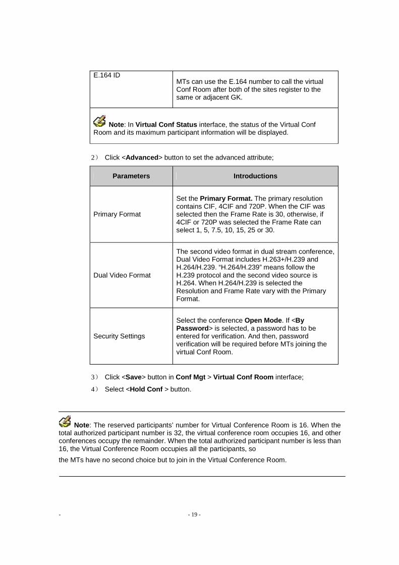
2) Click <Advanced > button to set the advanced attribute;
Parameters Introductions
Primary Format
Set the Primary Format. The primary resolution contains CIF, 4CIF and 720P. When the CIF was selected then the Frame Rate is 30, otherwise, if 4CIF or 720P was selected the Frame Rate can select 1, 5, 7.5, 10, 15, 25 or 30.
Dual Video Format
The second video format in dual stream conference, Dual Video Format includes H.263+/H.239 and H.264/H.239. “H.264/H.239” means follow the H.239 protocol and the second video source is H.264. When H.264/H.239 is selected the Resolution and Frame Rate vary with the Primary Format.
Security Settings
Select the conference Open Mode . If <By Password > is selected, a password has to be entered for verification. And then, password verification will be required before MTs joining the virtual Conf Room.
3) Click <Save> button in Conf Mgt > Virtual Conf Room interface;
4) Select <Hold Conf > button.
Note : The reserved participants’ number for Virtual Conference Room is 16. When the total authorized participant number is 32, the virtual conference room occupies 16, and other conferences occupy the remainder. When the total authorized participant number is less than 16, the Virtual Conference Room occupies all the participants, so
the MTs have no second choice but to join in the Virtual Conference Room.

- - 20 -
4.2 Hold Conference in the Virtual Conf Room
MTs can join the Virtual Conf Room simply by dialing the E.164 number, MTs will failure to join when the total authorized participant number is more than 16.
Note: The Virtual Conference Room can not invite MTs actively. 4.3 Stop Conf Room
Click <Stop Conf Room > button in the Conf Mgt > Virtual Conf Room interface can end the virtual Conf Room.
5 Monitoring
Use the MCC software to monitor the conference.
5.1 Current Conference
The current conference means a conference that is being held. To
go to Conf Mgt > Current Conf
O Shows all ongoing conferences;
O Shows the E.164 number of all ongoing conferences.
You can see the E.164 number of the Virtual Conference Room if it has been
started and hold conference in the Virtual Conference Room.
You may double click a conference name to enter the Boardroom . 5.2 Conference List
The Conf List is used to show all undergoing conferences, booked conferences, the Virtual Conference Room and the conference details and all MTs details of these conferences.
In this interface, the user can create, end or save conference.

- - 21 -
5.3 Conference Monitoring
To go to conference monitoring
O Select Conf Mgt > Current Conf, then double click a conference name;
O Click the right interface of Conference Information > Conf List in Boardroom interface, select conference name.
The default monitoring object is the first conference in the Conf List.
Shortcut icon explanation
large icons display, small icons display, tree type display,
conference mute (quiet), stop conference mute, conference dumb,
and stop conference dumb.
MT status icon
On Line MT, Off Line MT, Speaker MT,
Chairman MT, Speaker & Chairman MT
5.4 Site Video Monitoring
To monitor site video, PC performance required to meet the recommended standards, please go to Boardroom or Monitoring interface.
5.4.1 Site Monitoring in Boardroom
In the Boardroom , drag an MT’s icon to the monitoring window below.
The system can monitor up to nine MTs at the same time.
Right click on the monitoring window can complete various MT monitoring operations
O Stop Monitoring O Real-time Monitoring O Monitoring Mute O Monitoring Info O Full Screen

- - 22 -
O Capture Picture O Camera RC
5.4.2 Site Video Monitoring in Monitoring
Go to Monitoring , select an ongoing conference to be operated from the Conf
List drop-down, and then in the MT List, drag the MT to the monitoring window.
And the MT monitoring operations are not different from in Boardroom interface.
5.5 Site Polling
The site polling function means that the MCC plays the audio and video streams of the selected MTs at a designated internal according to a certain sequence.
To make solution for polling 1) Click the <Polling > under the Boardroom interface; 2) Select an MT from the MT(s) Available box, then click > 3) Click ↑ ( top), ↑ (previous), ↓(next) or ↓ (bottom) in the MT(s)
Selected list to change the sequence; 4) Set polling interval: double click the member in the MT(s) Selected list
to modify or fill in a unified polling interval in General Polling Interval(s) ; 5) Set the count of polling: “0” indicates the unlimited number of polling; 6) Click <Save> to save the solution. 7) If With Audio is selected, the MT will be polled with video and audio. To poll according the existing solution
1) Select a solution in Solution drop-down,
2) Click <Load >, and the original information will be loaded to the list;
3) Click <Start >.
5.6 Conference Status
Go to Boardroom , click <Status > button, then the status of the current conference are shown as follows:
O Mixing : It shows the MT(s) in Mixing list; O Continuous Presence : The MT(s) in Continuous Presence (CP) list will be

- - 23 -
displayed; O View : This list shows View MT, Viewed MT and View Type; O Send Back : The list shows the Send Back MT on Lower Level MCU, it is
available only in Combined Cascade Conference (See Part III, section 4.2).
6 MCC-Templates Management
SCS8000E can store up to 128 templates, use MCC to manage template reflected in the following:
O Create template O Modify template O Delete template
.
6.1 Create Template
Go to Conf Mgt > Templates, click Create to fulfill the template information.
Template information in the following table:
General Info
Parameters Introductions
name Conf Enter the conference name which is indispensable.
E.164 ID
Enter conference ID here, normally, E.164 ID are assigned by your system administrator. The E.164 ID can not be the same in a GK. If the MCU and MTs are registered in the same GK or adjacent GKs, the MT can call the E.164 ID of the MCU to start a conference or join in a conference.
Conf Rate The default value is 256Kbps.
Max Time Terminate manually or set the duration time, “0 Hour 0 Minute” indicates no time limit to the conference.
General Info—Advanced Info
Control Mode
If Need Password is selected, a password has to be entered for verification before other MCC to operate the conference, set password below; but no password is needed for local MCC operation.
Open Mode
Full Open: Any MT can participate in the conference without verification; By Password: Password verification is required before MTs joining the conference; Not Open: Only MTs invited to the conference can participate into the conference.
Security Settings

- - 24 -
Conf Password
The verification password of the conference, it is also a password for attending the Data Conference or for MCC to control the conference.
Encryption Select a encryption mode for transmitting information of a conference. If the user selects the Encryption , the encryption mode will be applied to all MTs.
Manual Key After the AES is selected in Encryption , set manual key.Cascade MCU must be set the same key when the Manual Key is selected.
Conference Call Mode.
The Conference Call Mode completes the MCU-call-MT settings: Timed: “0” indicates no limitation, the interval of calls made to each offline terminal when Timed is selected. The default value is 20s.
Accept Conf Cascade Cal
This option should be selected for both the superior and subordinate MCUs to support conferences to combine.
Enable IPLR Used to select whether to enable the IPLR (Intelligent Packet Loss Recovery) mechanism.
Advanced Settings
Auto End The conference will automatically end when no MT in the conference.
Discussion Conf
In discussion conference, the sound of all Ms will be mixed in the MCU and broadcasted to the whole conference, so that all MTs can be heard by each other.
Initial Mute At the beginning of the conference, MTs stop collecting audio signals, then the MCC or the MT to change this state after the beginning of the conference.
Data Conf
A data conference means the T.120 conference. The audio and video format of the conference will be set to G.711 ALAW or G.711 ULAW and H.263 when the data conference is needed.
Multicast The valid multicast IP addresses range from 225.0.0.0 to 231.255.255.255 and 233.0.0.0 to 239.255.255.255
How to deal with when no more terminals supported to carry on discuss
The MCU supports intelligent audio mixing contains 64 terminals at the most, You can select which way to deal with the situation that the terminals in discussion conference are more than the maximum intelligent mixing terminal number. The optional ways are Switch to Mix (custom mixing) and Stop Discussion.
Auto Record If this check box is selected, the user needs to select a online recorder to be used from the Recorder list.
Record Type It includes Daily and Weekly . Here, the user can set to make recording every day, a day or several days in a week.
Record Time Set the Start Time and End Time of record.
Record with Dual Video
If there are two channels of conference images are transmitted, these two image codes will be recorded at the same time.
Conference Record Settings

- - 25 -
Media Option
Video Format The SCS8000E MCU supports the H.264 and H.263 video compression standards.
Resolution If “H.264” is selected as the video format, the resolution of CIF, 4CIF, 720Pand 1080p/i can be selected from the drop-down list; while for the H.263 video format, only CIF resolution is supported.
Frame Rate The maximum frame rate is 30.
Audio Format Select the compression format from the drop-down list. General, the higher the audio sampling frequency, the better the quality of out-put sound.
Image Process
Only the opening of image processing functions will be allowed to call terminals with different resolution during meeting. The processing resource is exclusive for the conference selected the Image Process, in this case the other conference can not enable CP function or call different resolution MTs. If a conference has selected the resolution of 1080p/i the Image Process function is unavailable.
Media Option—Advanced Info
Video Format
Select the format of the second video source, including H.263+/H.239 and H.264/H.239. “H.264/H.239” means that the H.239 protocol is used and the format of the second video source is H.264.
Resolution
Refers to the dual video source resolution: VGA (640×480), SVGA (800×600), XGA (1024×768), WXGA (1024×512), SXGA (1280 × 1024) and 720P (1280 × 720). These resolutions are different under the condition of different Video Format and different Primary Resolution.
Frame Rate Set the maximum frame rate for the second video source.
Video Rate Used to select the percentage occupied by the second code stream in dual video format. The specific calculation formula is: the second code stream/ (conf rate – audio rate) ×100%.
Start Mode Select whether anyone or only the spokesman can star the dual video.
Dual Video Format
Video Quality
including Speed Precedence and Quality Precedence. Quality precedence policy ensures the image quality during the video transmission, so that the picture is free of mosaic or blue screen; while the speed precedence ensures the smoothness and consistency of the video.
VA Sensitivity
Under voice activation, the spokesman switching is implemented by judging the voice status of the MT. After the MT becomes the spokesman, no matter whether the MT is speaking, other MTs cannot seize its spokesman position in a set VA sensitivity period. Beyond this period of time, if the MT does not speak either, other MT with audio output will automatically become spokesman.
Other

- - 26 -
Speaker Recv
This option is used to select which video streams that the speaker will receive after a conference starts. If the selected object does not exist in the conference, the picture of the speaker itself will be received by default. If With Audio check box is selected, audio and video code streams will be received simultaneously.
Participants
name Enter the E.164 ID, IP address or H.323 ID of an MT to be invited. If Add to AddrBook option is selected, the MT information is added to the address book at the same time.
AddrBook Select an MT from the address book and add it to the invited MT list.
Option… Select an MT, click Option…. button to designate the MT call rate.
CP Enable the CP, select Broadcast Stream and CP with mt’s alias or not, then select Solution and Layout for the CP. In a 1080p/i conference the CP is unavailable.
6.2 Edit Template
Select a template from the Templates list, click <Edit> to enter the template editing mode. After editing related conference information, click <Save> to save the corresponding information.
6.3 Show Template Information
Select a template from the Templates list, click <Edit > to enter the template editing mode, after view the related information, click <Cancel >.
6.4 CopyTemplate
Select a template to be copied from the Templates list, click <Copy >, the name and E.164 ID of the new template automatically change or you can reset them manually, and then click <OK>.
6.5 Delete Template
Select a template to be deleted from the Templates list, and click <Delete> to delete it.
6.6 Conference and Template
Once the conference has been started in accordance with the established template, the conference and the template are not correlative.

- - 27 -
7 MCC- Conference Management
Depending on MCC software to manage conference, participating terminals and switching the conference mode to achieve a perfect control of the conference functions.
7.1 MCC-Conference Control
The control of conference including Prolong Conf , Conf Password , MT Video
Source and so on.
Go to Boardroom to execute the operations. 7.1.1 Prolong Conf
The time can be prolonged during a timed conference.
Prolong Tips
15 minutes before the end of the conference, there will be a pop-up interface. Need to prolong the conference, enter the time.
To Prolong Manually
Go to Boardroom , click Settings , select the Prolong Conf in the pop-up menu, entering the time.
7.1.2 Conf Control
Click Settings in Boardroom interface, select Conf Control in the pop-up menu.
O Full Open: Each MCC user can operate the conference and participating MTs; O By Password: password verification is required when other MCC user operate
the conference; O Not Open: The conference is monopolized by the local MCC user, and other
users cannot make any conference operations. 7.1.3 Conf Password
Used to enter or change the conference control password.
Click Settings in Boardroom , select Conf Password in the pop-up menu.
In the Modify Password interface:
1) Enter the old password;
2) Enter the new password;
3) Confirm the new password.

- - 28 -
7.1.4 Conference Recording
Conference recording needs the support of the Live Conferencing Recorder.
Recording
1) Click Settings in Boardroom , select Record ; 2) Select online recorder, click <start >; 3) Enter the record-file name in the pop-up interface and select record mode;
O Strobe Recording: Used to record video streams in key frame mode;
O Record with Dual Video: If Record with Dual Video is selected, the two channels of code streams of the picture will be recorded; otherwise, only one channel of code stream will be recorded.
Recording interface can display the currently recorded time length in real time, in units of seconds.
7.1.5 Switching Participating MT Video Source
Some of the participating MTs with two video source: Video Source 1 and Video Source 2, Video Source 1 is usually a built-video source, Video Source 2 is an external.
Switch Video Source in two easily methods
Method 1
Click Settings in Boardroom , select MT Video Source in the pop-up menu.
Way 1
1) Select a solution in the list;
2) Click Load .
Way 2
1) Select an MT from the MT(s) Available list; 2) Choose a video source port from the Video Source Port drop-down list;
3) Click or , put the designated terminal into MT(s) Selected list.
Way 3
1) Click or , put the designated terminal into MT(s) Selected list; 2) Select the MT in MT(s) Selected list, right click, choosing a video source port.
The user can also save the video source settings as solution; load existing solution; and delete unnecessary solution.
Method 2
Right click the MT in Boardroom interface, then select Video Source > Video Source 1 (Video Source 2 ).
If the selected video source does not access, the MT’s video screen prompts no video source, select the video source connected normally.

- - 29 -
7.1.6 Start/Stop Discussion
To start discussion conference will occupy the mixer resources on the MCU. When the resource is sufficient you can start the discussion conference.
Start
Click Settings in Boardroom , select Discussion in the pop-up menu. The SCS8000E supports up to 32 MTs to join a discussion conference.
Stop
During the discussion conference, select Discussion once again to stop it.
7.1.7 Mixing
Conference in mixing status, only the designated members can join the discussion, and other members receive the sound of the members of the discussion group, the speaker takes the initiative in occupying a mixing channel.
Mixing can select MTs through single mode or extend mode.
The operating procedure for the Single Mode is as follows:
1) Click Settings in Boardroom , select Mixing in the pop-up menu;
2) In the Mixing Style field select the number of mixing channels; SCS8000E
supports up to 32 channels; 3) Drag the MTs from the boardroom to each channel, and click <Start > ; 4) Click a mixing channel, and the mixing of the MT will be ended.
Under the premise of mixing, if another MT requests to chime in, the MT can automatically participate into the mixing group after the approval of the MCC or the chairman.
The operating procedure for the Extend Mode is as f ollows:
1) Select an MT (tick the check box before the MT) to be added to the mixing
group; 2) Click <Start > to start mixing; 3) Click <Stop > to stop mixing.
Note: If the previous operation of the mixing is single model, it will automatically access to
the single mode next time. With he Extend Mode situation is the same as the Single Mode.

- - 30 -
7.1.8 CP
CP Settings
1) Go to Conf Mgt > Templates > Create , click <Participants > ;
2) Click CP in Invited MT Settings interface;
3) Tick the Enable CP in the pop-up interface, by default, Broadcast Stream and CP with mt’s alias are selected (it can be canceled according to actual needs);
4) Select solution (To use an existing CP solution, which including the picture frame and background) and layout;
o “Dynamic " indicates that the system will automatically determine the layout according to the number of participating MTs.
5) Select an MT from the MT list and drag it into the CP channel, click <OK> and <Save>;
6) Use this template to start a conference which is in CP status;
7) Click Settings in Boardroom , select CP in the pop-up menu, then click
<Stop > to exit.
Broadcast Stream means broadcast the CP stream, the participant receives composite image. The MT’s alias or E.164 number will be attached on the small picture in CP when CP with mt’s alias is selected.
Start/stop CP
If a holding conference did not set the CP, you can follow these steps to start CP in the conference:
Click Settings in Boardroom , select CP on the pop-up interface, and then select Solution and Layout on the Continuous Presence interface, drag MTs to the layout window (For more information see SCS8000E Quick Start Guide), tick or do not tick Broadcast Stream and CP with mt’s alias , click Start /Stop to start or stop the CP.
CP Channel Operations
Clicking an occupied channel, and then the user can make settings as follows: O Set by MCC: only the chairman MT and the MCC can specify the channel video
source; O Speaker Picture: the channel will show the speaker images; O Chairman Picture: the channel will show the chairman images; O Polling Picture: the channel show polling images when video polling.

- - 31 -
7.1.9 Message Click Message in Boardroom , edit the contents of the message, then send to participating MTs.
How to send message
1) Fill in the parameters and the contents of the message;
2) Select MTs who will receive the message;
3) Click < Send>.
What are the parameters need to set up
Parameters Introductions
Type The way message scroll on the screen.
Scroll Times Up to 255 times
Speed Rolling speed
Edit The maximum length of a message is 1024 bytes, the maximum
Message number of Leftward caption is 26 lines, and the maximum Paged Upward caption is 26 lines.
Send Daily Message
Edit Daily Message , then Save in the Daily Message box.
Choose a saved message from the drop-down box, then click Select .
Load file message
Click <Load > to load a message from a TXT file to the above Edit Message box.
After sending the message successfully, the user can click the <Stop > button, and then the message that is being shown on the receiving terminals’ screens will disappear.
7.1.10 Voice Activation
Under voice activation, the switching spokesman is implemented automatically.
Conditions as the Spokesman
The speech sound is the biggest and the duration is longer than the VA Sensitivity will become spokesman.
Start VA
Click Settings in Boardroom interface, select Voice Activation in the pop-up menu. After the Voice Activation was enabled, click Settings and select VA Settings to reset the VA Sensitivity .
Stop VA
Click < Settings > in Boardroom , select < Voice Activation > once again in the pop-up menu to stop the voice activation.
- - 32 -
7.2 MCC–MT Management Go to Boardroom to execute the operations.
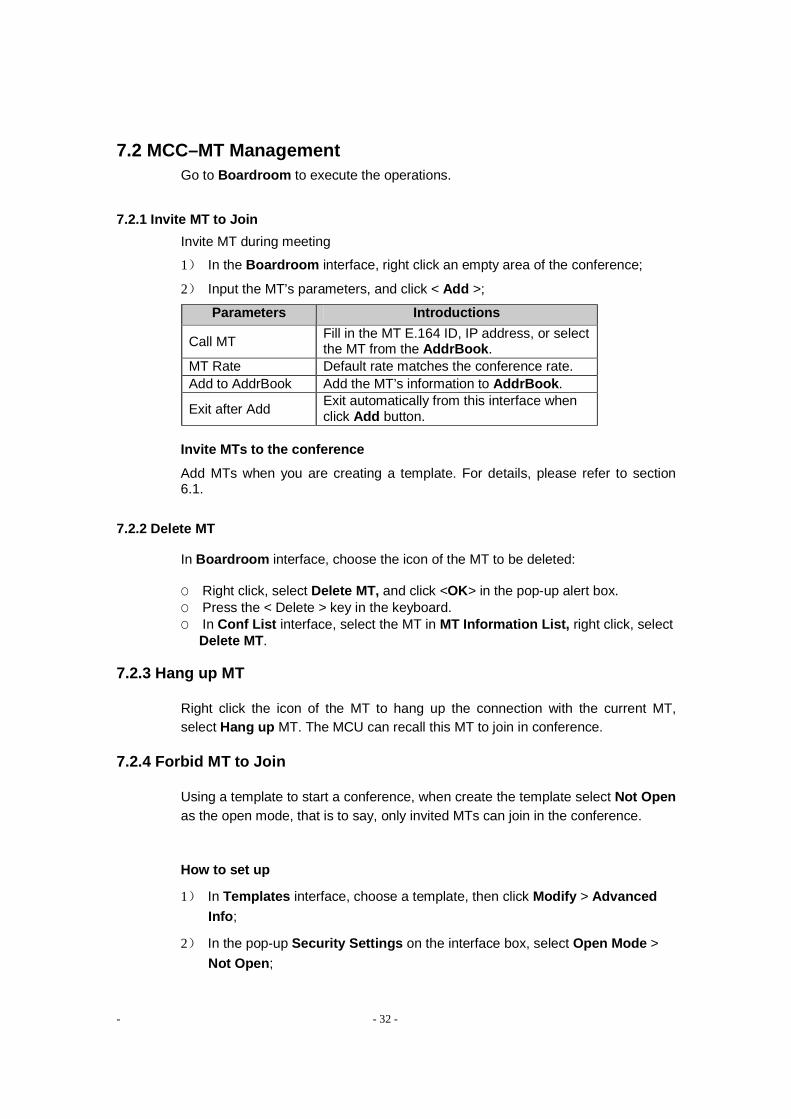
7.2.1 Invite MT to Join
Invite MT during meeting
1) In the Boardroom interface, right click an empty area of the conference;
2) Input the MT’s parameters, and click < Add >;
Parameters Introductions
Call MT Fill in the MT E.164 ID, IP address, or select the MT from the AddrBook .
MT Rate Default rate matches the conference rate. Add to AddrBook Add the MT’s information to AddrBook .
Exit after Add Exit automatically from this interface when click Add button.
Invite MTs to the conference
Add MTs when you are creating a template. For details, please refer to section 6.1.
7.2.2 Delete MT
In Boardroom interface, choose the icon of the MT to be deleted:
O Right click, select Delete MT, and click <OK> in the pop-up alert box. O Press the < Delete > key in the keyboard. O In Conf List interface, select the MT in MT Information List, right click, select
Delete MT . 7.2.3 Hang up MT
Right click the icon of the MT to hang up the connection with the current MT, select Hang up MT. The MCU can recall this MT to join in conference.
7.2.4 Forbid MT to Join
Using a template to start a conference, when create the template select Not Open as the open mode, that is to say, only invited MTs can join in the conference.
How to set up
1) In Templates interface, choose a template, then click Modify > Advanced Info ;
2) In the pop-up Security Settings on the interface box, select Open Mode >
Not Open ;

- - 33 -
3) Click < OK>, and save the modified template.
7.2.5 Set the Role of MTs
The role of MTs in three sub-terminals: chairman, spokesman and common terminals. The role of the different roles and conference operations, please refer to Samcen Series User Manual.
The role-set can be operated before the conference start or after.
Set the role before the conference start
1) Go to Conf Mgt > Templates, select a template, then click Modify;
2) Click MT List , select MT in the pop-up interface;
3) Right click, then select Set as Chairman or Set as Speaker ;
Specify the role after the conference start
Go to the Boardroom interface, right click a MT’s icon, then select Set as Chairman or Set as Speaker ; certainly, you can drag the MT’s icon to the chairman/speaker’s position to complete the same operation.
When cancel the corresponding role-set by right click or other MT become chairman/speaker the original role will be replaced automatically.
7.2.6 Set the Content of the MT View
MT View means to have one MT to receive the audio and video of another MT.
How to set MT A to view MT B
Method 1
1) Go to Boardroom interface, right click the icon of MT A, select MT View in the pop-up menu;
2) Select View Type in the pop-up interface, then double click the icon of MT B.
Method 2
1) Go to Boardroom interface, drag MT A to the position of MT B;
2) Select View Type in the pop-up interface (View type includes A / V, Audio and Video ).
7.2.7 Set MT Mute/Dumb
The MT that set to be mute will not hear sounds of other MTs. After
dumb enabled, other MTs cannot hear the voice of dumb MT.

- - 34 -
Go to Boardroom interface, click to select the MT:
O Select conference mute (quiet), stop conference mute,
conference dumb, and stop conference dumb.
o Right click to select the MT Mute /MT Dumb in the pop-up menu,
the corresponding selection button of the terminal have been
mute or dumb was ticked.
In the MT Information box tick or undo-tick Mute /Dumb selection. 7.2.8 Adjust Input/Output sound of the MT
The MT input means peripheral’s volume input to MT, such as microphone; output is the output to peripherals such as television or audio.
How to operate
Go to Boardroom interface, click to select the MT, In the MT Information box drag the block of Volume(In)/Volume(Out) .
Note: When adjust the output volume, we recommend to adjust peripheral (the television
or stereo) as a priority.
7.2.9 Camera Remote Control
Right click the icon of MT in Boardroom interface, select Camera RC in the pop-up menu.
The user can conduct such camera operations as move (Up, Down, Left and Right), Focus (auto/manual), Zoom, Brightness, Preset, Save, and Load.
7.2.10 Display MT Information
Select an MT icon in the Boardroom interface, and the MT information will be displayed on the right column of the interface, such as, MT Alias, Call Mode, Transmitting Rate, Audio Source, Video Source, and MT Status. Furthermore, the user can also set Mute, Dumb, Volume (In), and Volume (Out) of the MT.
7.2.11 Other Operations
Right click the MT’s icon in Boardroom interface, you can further conduct operations by follows:

- - 35 -
Refresh Alias
Refresh the alias of a selected MT.
MT Call Mode
The MT recall mode after the MT is offline or restart. The user can select manual call or timed call on this interface.
Add to AddrBook
Add the MT information to the address book.
8 MCC-MCU Management
The MCU management includes the following interfaces: General Info, MCU Settings, Peripheral, Address Book, User and Setup Wizard.
8.1 MCU General Information
Go to MCU Mgt > General Info interface, to view the current status of the SCS8000E MCU.
O CPU Utilization: Displays the CPU utilization of the MCU.
O Register to GK: Displays whether the MCU has registered to GK or not.
O Number of Conf: Displays the number of ongoing conferences and booked conferences in the MCU.
O Online MT: Displays the number of participating MTs in the MCU.
O MCU Running Time: Shows the running time of the MCU since it has run.
Click <Refresh >, and real-time display of the latest general information of the MCU.
Click <Refresh >, and real-time display of the latest general information of the MCU.
Click < MCU Config Info >, and you can see the detailed configuration information and the network topology.
Time Settings
Shows the current MCU time, click <Sync with Local > button to synchronize the MCU time with the local system time.
Version Information
Display this information including the maximum authorized number of MTs, PCMT authorization number and the MCU hardware version. The PCMT authorization number is included in Authorization Num .

- - 36 -
Click < Upgrade MCU > can upgrade SCS8000E, for detailed operation, please refer to the section three of Version Upgrade.
Click <MCU License > to import the MCU license file. If you have not authorized license file, you can through automatically generate the MCU message to get the file.
8.2 Peripheral Status
Go to MCU Mgt > Peripheral , can view the MCU has enabled currently peripherals’ basic information.
Select a peripheral you can view the online status of the peripheral and more information.
In this interface displays the statuses of “CP Unit”, “Mixer”, “BAS”, “PRS”, “Private proxy of Samcen”, “GK”, “H.460 Server” and “Data Conference Server”.
The upper half field shows the peripheral list, including the information of Equipment name, Online, and so on. Select a peripheral (such as Mixer), the detailed equipment information will be displayed in the lower half field of the interface.
8.3 MCU Settings
The MCU Settings is used to complete such configurations as LAN, Qos, CP, and other settings.
Go to MCU Mgt > MCU Settings to setup MCU. 8.3.1 LAN Settings
In LAN interface to configure the network information:
The System’s Deployment: Display the network deployment and the proxy.
Adapter Name: Shows the NIC that is being used, if there are several adapters , you can select the one you want to use. Then the information of MCU Address, Subnet Mask and Gateway is just the adapter’s corresponding information what you have configured. You can modify the configured information.
Data Recv. Port : The range is 61000-64255. Default value is 61000, and the best use of the default value.
H225/H245 Start Port : The range is 60002-65279. Default value is 60002, and the best use of the default value.
Private proxy start port : The range is 48000-49720. Default value is 48011. Or H.460 server start port : The range is 48000-49720. Default value is 48011.

- - 37 -
MCU Alias : Setup the MCU alias.
E.164 ID: Setup the E.164 ID of the MCU. The E.164 ID is mainly used to GK
registration and calling.
After completing settings, click <Save> button.
8.3.2 Qos Settings
The Qos (Quality of Service) settings are used to get satisfied video quality. We recommend best use of the default settings.
If you have to change the default value, please click <Edit > button in the lower right corner of this interface.
Qos Type : DiffServ or IP Precedence.
o DiffServ: used to define which priority Audio, Video, Data and Signaling packets transmission should have in an IP network. The priority ranges from 0 to 63 for each type of packets. The number 0 indicates the lowest priority, and the number 63 indicates the highest priority.
o IP Precedence: used to assign a priority level to Audio, Video, Data and Signaling packets should have in a network device.
The IP ToS (Type of Service) is used to help the network devices (such as routers) select a service type when handling the datagram.
o Delay: minimize the delay;
o Throughput: maximize the throughput;
o Reliability: maximize the reliability;
o Cost: minimize the cost.
MTU: Maximum Transmission Unit, this parameter is set according to the actual network conditions. The value ranges from 1308 to 1468.
8.3.3 Solution of CP
To set the CP background color, the frame color and other appearances.
How to set the CP solution
1) Go to MCU Mgt > MCU Settings > CP, select a solution;
2) Set the CP background color and the frame color of each member (including the speaker, chairman and normal).

- - 38 -
3) Click <Rename> to rename the solution.
8.3.4 Other Settings
Select <Other > button, you can complete following settings:
Save Bandwidth of MT (s) When not Transmitting Stre aming : It is used to
select whether to decrease the bandwidth usage of MTs who do not need to
transmit streaming.
Round Trip Delay(s): Set the test interval, at which the system will test the
network connection status of the MT after the connection is established.
Round Trip Delay Count: Set the retry count of automatic test, available only
when the connection fails.
MT List Refresh Interval(s) : Used to set the MT list refresh interval of a cascade
conference.
Video Source Refresh Interval(s) : Used to set the video source refresh interval
of a cascade conference.
Audio Source Refresh Interval(s) : Used to set the audio source refresh interval
of a cascade conference.
Enable Data Conf Server : This option is used to select whether to enable a data
conference. After selecting Enable Data Conf Server , enter the IP address of the
data conference server.
You can use DCC (Data Conference Console) software to manage the data
conference. For detailed operations, please refer to corresponding introductions.
9 User Management
The MCC user belongs to a user group, the group has the following advantages:
o Any user belongs to a user group. Users in the same group share their
resources (templates, conferences, and so on).
o If the creation of a conference is initiated by an MT, all MCC users of the MCU
can control the conference.
o After a MCC user group is deleted, all MCC users contained in the group will
be deleted either, and furthermore, the resources related to these MCC users

- - 39 -
will be deleted either.
Users are divided into three levels based on their rights: Super administrator,
administrator and operator.
o Super administrator: Can make complete control over the MCU;
o An administrator can support all the control functions except MCU
configuration; however, it can only manage conferences and templates
created by itself or users in its own group;
o An operator supports all the control functions except user management,
template management and MCU configuration; however, it can only manage
conferences created by the administrator of its own user group.
In the User interface, the administrator can add, modify or delete user group and user information.
9.1 Adding/Deleting/Modifying User Group
Adding a user group
1) Click <Add Group > button; 2) Enter the user group information in the pop-up interface: o Group Name: Enter the name of the user group;
o Group ID: Enter the ID number of the user group;
o Max User Num: It is used to set the maximum number of users in a user group;
o Auth IP Range: It is used to set the IP address range of MTs that are allowed or forbidden to call the MCU.
� Allow: Only MTs in the set range are allowed to be called to join in a conference (template) created by the user group;
� Forbid: MTs in the set range are forbidden to be called to join in a conference (template) created by the user group.
Note: The Auth IP Range is only valid for MTs that call the MCU initiatively. The MTs that
the MCU calls initiatively to join in a conference are not restricted. A user group can set three
forbidden/allowed IP ranges at maximum.
Deleting a user group
1) Select a MCC user group, then right click and choose <Del Group >;
2) Click < OK > button in the pop-up interface.

- - 40 -
Modifying a user group
1) Select a MCC user group, then right click and choose <Edit Group >;
2) Modify the group information in the pop-up interface, click <OK> button to take
the changed contents effect.
9.2 Adding MCC users
1) Select a MCC user group which is going to add users, click <Add User >
button in the user information column; 2) Fill in the correct username, password, and permission and so on, then click
<OK> to complete.
10 Address Book
Address Book records the group to which the participating MT belongs and the detailed address entry.
The group is a set of a group of address entries. To use the group is convenient to manage and use.
The address entry is the detailed information of the MT. It includes the MT name, IP address, E.164 ID and H.323 alias.
Go to MCU Mgt > Address Book to manage the address book. 10.1 Address Entry
Adding an address entry
1) Go to Address Book interface, then click < Add >;
2) Fill in related information of the MT in the pop-up interface, then click <OK>
button and the entry can be added successfully.
Editing an address entry
1) Select a MT entry;
2) Click the <Edit > button in the address entry column, then edit corresponding
information in the pop-up interface;
3) Click <OK> to complete.
Finding an address entry
1) Enter the keyword in the address entry interface, such as MT name, H.323 ID,

- - 41 -
E.164 ID or IP address;
2) Click <Search Next >.
10.2 EntryGroup
Adding an entry group
1) In the bottom of the Address Entry list, click <Add >;
2) Fill in the name of the entry group, and click <OK>.
Editing an entry group name
1) In the Entry Group list, select an entry group to be edited;
2) Right click, select <Edit >, then enter a new name of the entry group in the
pop-up interface, click <OK> to complete.
Adding a group member
1) In the Entry Group column, select a group needing add existing entries;
2) Right click to select <Add Member > button;
3) Select an MT from the Entries Available list in the left of the pop-upinterface, click 【>】or 【>>】button to import the selected entries to the Entries Selected
list of the MCU by selecting single entry or all entries.
4) Click <OK>, and the member can be added successfully.
11 MCC-Preferences
Go Preferences > User Settings interface, to set the user's personalized application:
Visible menu and interface language of conference;
O MTs’ large icons status display;
O Monitoring methods.
11.1 User Interface Settings
According to need, the user can customize menu, the information of list and the interface language.
Menu includes conference setting menu and MT shortcut menu. The customized contents will display in the Boardroom interface.
List includes conference information list and MT information list. The customized contents will be display in the Conf Mgt > Conf List interface .

- - 42 -
Custom menu
1) Go to Preferences > User Settings >User Interface Setting s interface, tick the Custom Menu ;
2) Click <Config… > button, then configure the Conf Setting Menu or MT Shortcut Menu in the pop-up interface;
3) Select menu item, click the moving-button to make corresponding menu displayed or hidden;
4) Click <Save> after set and exit.
Custom List
1) Go to Preferences > User Settings > User Interface Settings interface, tick
the Custom List; 2) Click <Config… > button, then configure the Conf Info or MT Info in the pop-up
interface; 3) Select list item, click the moving-button to make corresponding menu
displayed or hidden; 4) Click <Save> after set and exit.
11.2 MT Status Icon in Boardroom
In Boardroom interface, when the MT is displayed with large icon the status of the MT can be indicated by an additional small icon. For example, means the MT is dumb,
How to set
1) Go to Preferences > User Settings > MT Status Icon in Boardroom interface;
2) Using the <Display All > button and <Display None > button can check or uncheck all the icons in the same time or you can manually select some of them.
If the MT is displayed with small icon it does not have an impact. 11.3 Monitoring Settings
Monitoring includes No monitoring and Camera Strobe Monitor.
For the high performance PC, we recommend to enable the monitoring function.
Go to Preferences > User Settings > Monitoring interface to set the way of monitoring:
o No Monitoring : If this option is selected, it indicates that after a conference
starts, the MCC is not allowed to monitor MTs.

- - 43 -
o Camera Strobe Monitor : Used to select whether to make strobe playing
when a camera is used for picture monitoring. If there is no high requirement for image continuity, this option can be enabled to play key frames, in order to reduce the bandwidth usage.
11.4 Event Log
In Preferences > Event Log interface, you can view, export and delete the event log.
View event log
The event log list record the type, time and detailed information of all operations.
In addition, you can click button to view the event log in the main interface.
Export event log
Click the <Save As… > button at the bottom of the Event Log interface, then set the path and file name in the pop-up interface, click <Save> to complete.
Delete event log Delete log entries: select a log entry in the log list, right click <Delete>. Delete all log entries: click <Clear> button at the bottom of the interface, then select <OK> in the pop-up interface.
- - 44 -
Section Three Related Services and Applications
1 Gatekeeper Services
SCS8000E has integrated Gatekeeper (Referred to GK). services, which mainly provides such services as registration management, address resolution, call admission control, bandwidth control, zone management, call control signaling, call permissions, call management.
The Services can through Gatekeeper Console (Referred to GKC) to manage.
1.1 Environment Requirement of GKC Installation
GKC software runs on the PC.
Hardware Configuration
Recommended PC Configuration: Pentium 4 1.8 G and above; 256MB Memory and above.
Software Configuration
Operating system: Windows 2000 or above
IE: Microsoft Internet Explorer 6.0 and above
1.2 GKC Installation
Installation Methods
Method One: Use SCS8000E packaging CD, select “Install The Gatekeeper
Console Software” to install.
Method Two: Enter such address as “IP of SCS8000E/gk.html” in the URL to
install.
If a security setting alert appears in the initial use, please click <Yes> to launch
the auto-installation. Pop-up login interface when the installation complete.
For detailed information on login the GKC, please refer to the GKC Software Help
file.

- - 45 -
2 Data Conferencing Services
SCS8000E supports video conferencing and data conferencing to work cooperatively. A data conference means that the T.120 data transmission protocol is used for data transmission during a conference, so as to support such conference applications: electronic whiteboard, file transfer, chat and sharing programs.
Data conferencing can through Data Conferencing Console (Referred to DCC) to manage.
2.1 Environment Requirement of DCC Installation
DCC software runs on the PC.
Hardware Configuration
Recommended PC Configuration: Pentium 4 1.8 G and above; 256MB Memory and above.
Software Configuration
Operating system: Windows 2000 or above
IE: Microsoft Internet Explorer 6.0 and above
2.2 DCC Installation
Installation Method:
Use SCS8000E packaging CD, select “Install The Data Conf Console Software” to install.
If a security setting alert appears in the initial use, please click <Yes> to launch the auto-installation. Pop-up login interface when the installation complete.
For detailed information on login the DCC, please refer to the DCC Software Help file.

- - 46 -
3 Video Conferencing Live Online
Through Live Conferencing – a conference recording and broadcasting system and with the use of SCS series MCU, then the video conferencing can be broadcasted online, on-demand and download the video conferencing.
The installation and application of Live Conferencing, please refer to Live Conferencing User Manual.
4 Cascade Conference
Cascade conference means a joint of conferences ongoing in different MCUs.
4.1 Simple Cascade
This kind of cascade conference applies to combine conferences holding on the Samcen MCU and other manufacturer’s MCU.
Characteristics
o The cascaded MCU (no matter the master or the slave) cannot view MTs of other MCUs;
o The slave MCUs are cascaded as a MT;
o The master MCUs passively accept the streams sent by slave MCUs, cannot
operate the MTs of slave MCUs.
How to hold simple cascade conference
Preparation:
To hold a simple cascade conference, the master or the slave MCUs should not select the Accept Conf Cascade Call option in the General Info >Advanced Info > Advanced Settings interface.
Method one:

- - 47 -
o When creating a conference template on the master MCU, add the E.164
number of the conference in slave MCU into its participant list.
Method two:
o After a non-cascade conference created on the master MCU, call the E.164
number of a slave MCU’s conference just as call a MT into the conference.
4.2 Combined Cascade
Combined cascading MCUs are all Samcen’s MCU. Both the MTs of the master MCUs and slave MCUs can be viewed by MCU.
Characteristics
o Increase in the number of participating terminals, each slave MCU occupies a
channel to transmit data;
o Facilitate management, each participating MT is authorized by a specified
MCU.
o A MCU can control MTs of its slave MCUs.
How to hold combined cascade conference
Preparation:
To hold a combined cascade conference, the Accept Conf Cascade Call option should be selected both in the conference templates of all combined MCUs.
Method:
The creating method for the combined cascade conference is the same as that for the simple cascade conference.
Operations can be carried out in combined conference
o The master MCU can conduct control over all participating MTs in the
directly-connected slave MCU, such as, adding, deleting, calling, hanging up, camera RC, and vide source switching.
o The chairman in each MCU can only control the MTs under the local MCU,
and cannot control MTs in a different level of MCU.
o The system supports the master MCU to designate any MT under the
directly-connected slave MCU to become the speaker of a conference.
o Each MCU can view MTs of master MCU, slave MCU and its own, adjacent
MCUs cannot view MTs of each other.

- - 48 -
o In a combined cascade conference, when CP is conducted in a master MCU,
its member can be an MT of the local MCU or an MT of a slave MCU (a slave MCU only supports one MT). If CP is performed in a slave MCU, its member can be an MT of the local MCU or the broadcast channel of the master MCU. After the CP operation, the CP pictures are not required to be sent to the master MCU.
o A master MCU can designate an MT (only one is supported) of a slave MCU
to be displayed on the monitor wall of the master MCU. A slave MCU can designate whether pictures from its master MCU are displayed on the monitor wall of the slave MCU.
o If the conference discussion mode is used, an MCU will automatically start the
local mixer (in discussion mode) .
o If custom mixing is used, a master MCU is supported to select several MTs of
its own and certain MTs of its directly-connected subordinate to participate in custom mixing.
o In a combined cascade conference, each level of MCU can only control the
recorder of the local MCU. A master MCU can designate an MT of a slave MCU to make recording in the master MCU. A slave MCU can designate its master MCU to make recording in the slave MCU.
o In a combined cascade conference, the user is allowed to conduct such
operations as view and MCC monitoring. The MT from master MCU is allowed to view the MT of the directly-connected slave MCU, and the MCC of the master MCU is allowed to monitor the MT of the directly-connected slave MCU (an MCU only supports one MT). The MT from slave MCU is not allowed to view the MT under the master MCU, and the MCC of the slave MCU is not allowed to monitor the MT under the master MCU.
o In a combined cascade conference, an MCU is supported to poll all online
MTs of the local MCU and all online MTs of the directly-connected slave MCUs. Two cases are involved when an MT in a slave MCU speaks in the local MCU: Only video polling can be conducted, and the polling of and broadcast to all MTs in the MCU cannot be made; Polling of audio and video can be conducted. The polling of and broadcast to all MTs in the MCU can be made.
o In a combined cascade conference, the MCC connected to the master MCU is
supported to be set to monopolizing the entire conference, and other MCCs can only view pictures, without any operation right.
o In a combined cascade conference, an MCU is supported to send messages
to the MT of its own or of the slave MCU.
o When a combined cascade conference is created, the speaker of each MCU

- - 49 -
is independently controlled by the MCU itself. If a slave MCU does not have a speaker, the conference held on the MCU is in no speaker status.
5 Version Upgrade
Use MCC software to upgrade the MCU version.
Preparation:
o Confirm the current MCU version;
o Login website:http//www.samcen.com to download corresponding version documents to local PC.
Update Operations:
The upgrade file of SCS8000E is mcuupdate.bin;
1) Start the MCC software, then go to MCU Mgt > General Info interface, click <
Upgrade MCU > button;
2) Click < Select Files > in the pop-up interface, then select a file needed to
upload;
3) Click < Upgrade > button, the file will automatically upload;
4) After the completeness of uploading, reboot the SCS8000E to make the
upgrade into effect.
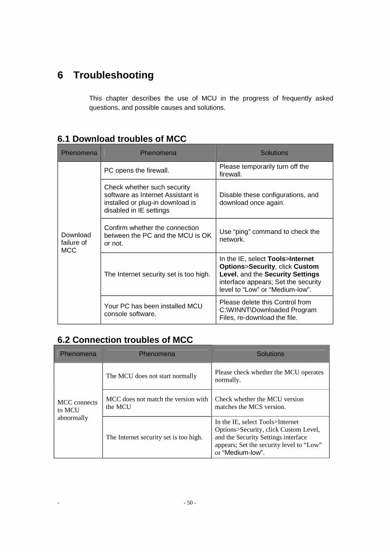
- - 50 -
6 Troubleshooting
This chapter describes the use of MCU in the progress of frequently asked questions, and possible causes and solutions.
6.1 Download troubles of MCC
Phenomena Phenomena Solutions
PC opens the firewall. Please temporarily turn off the firewall.
Check whether such security software as Internet Assistant is installed or plug-in download is disabled in IE settings
Disable these configurations, and download once again.
Confirm whether the connection between the PC and the MCU is OK or not.
Use “ping” command to check the network.
The Internet security set is too high.
In the IE, select Tools >Internet Options >Security , click Custom Level , and the Security Settings interface appears; Set the security level to “Low” or “Medium-low”.
Download failure of MCC
Your PC has been installed MCU console software.
Please delete this Control from C:\WINNT\Downloaded Program Files, re-download the file.
6.2 Connection troubles of MCC
Phenomena Phenomena Solutions
The MCU does not start normally Please check whether the MCU operates normally.
MCC does not match the version with the MCU
Check whether the MCU version matches the MCS version.
MCC connects to MCU abnormally
The Internet security set is too high.
In the IE, select Tools>Internet Options>Security, click Custom Level, and the Security Settings interface appears; Set the security level to “Low” or “Medium-low”.

- - 51 -
Phenomena Phenomena Solutions
PC opens the firewall. Please temporarily turn off the firewall.
Your PC has been installed MCU console software.
Please delete this Control from C:\WINNT\Downloaded Program Files,re-download the file.
6.3 Troubles of MT joining conference Phenomena Phenomena Solutions
The connection between MCU and MTs failed.
Use “ping” command to check the network..
Use the E.164 number or H.323 alias to call an MT, but the MT has not register to GK.
Check the status of MT registration to GK in the MT’s main interface.
The conference holding on the MCU was encrypted, but the MT did not set encryption.
Check the encryption settings between MCU and MT.
Some MTs cannot join a conference after the conference has started.
MTs have been connected to the MCU over the number of authorized.
With MCC software, enter the MCU Mgt > General Info interface to check the authorized number. Or attempt to withdraw some MTs from conference.
6.4 Troubles of camera remote controlling
Phenomena Phenomena Solutions
The camera you selected to control does not support PTZ controlling.
Make sure that the camera you selected supports PTZ controlling.
Controlling MT’s camera failed during conferencing. The MT you selected does not
allow Far End Camera Control. Make sure that the FECC function is enabled for the MT you selected.

- - 52 -
6.5 Troubles of pictures Phenomena Troubles Solutions
Speaker video source fault. The speaker makes a self-test to check the picture effect.
After setting an MT as speaker, all the other participants can not view its images.
Speaker’s call rate is too low.
Speaker withdraws from the conference, then matches the conference rate to recall the conference.
Monitoring is disabled
Make sure whether No Monitoring is selected in Preferences > User Settings > Monitoring interface. If selected, please undo it.
Decoder error Please reinstall the MCC, which contents decoder.
MTs are dragged to the monitoring window of the MCC, but no pictures are displayed.
The Operating system had installed MCC software is Windows Vista, in addition, the PCMT software, MTC software and Kaspersky Anti-Virus software are enabled.
Please temporarily turn off the Kaspersky Anti-Virus software.
6.6 Others
Phenomena Phenomena Solutions
The audio card driver of the PC of the MCC is not successfully installed
Please check whether the audio card driver of the PC of the MCC is successfully installed.
Decoder error. Please reinstall the MCC, which contents decoder.
If the codec has already been installed, but it is of lower priority.
Reset the priority of the codec.
An error report as “Codec error in turning on audio card” or “Decoder error in turning on audio codec” appears when monitoring images
The audio card software conflicts with other software ports.
Recommend to mask other conflicting ports conference.

- - 53 -
Appendix A Port Usage of SCS8000E
This chapter mainly introduces the port usage of SCS8000E MCU, you may need the following information when configure the firewall of video conferencing system.
SCS8000E MCU start port default value of the UDP, TCP:
Data Receive Port: Default value is 61000.
H.225/H.245 Start Port: Default value is 60002.
In a variety of network deployment, when the SCS8000E uses default value of
UDP and TCP ports please refer to following table:
Network Deployments Port Number Functions
61000-62280 dynamic UDP Media ports
1719 static UDP RAS ports
1720 static TCP H.225 ports LAN Network/WAN Network
60002–60258 dynamic TCP H.245 ports
2776–2777 dynamic UDP Proxy Server ports Enable private proxy of Samcen 2776–2777 dynamic TCP Proxy Server ports
48000–50000 dynamic UDP Media ports
1719 static UDP RAS ports
1720 static TCP H.225 ports
LAN and WAN Mixed Network Enable H.460
proxy
59000-60000 dynamic TCPH.460 ports
If you modify the default value of data receive port and H225/H245 Start Port, the SCS8000E will automatically adjust the range of UDP Media port and TCP H.245 port basing on your modified default value.
The range adjustment conforms to the following regu lations:
o UDP Media Port: Data Start Port (Initial Value is 61000)->61000+1280;
o TCP H.245 Port: Initial value of H225/H245 Start Port is 60002->60002+ 256

- - 54 -
Appendix B The Media Processing Ability of SCS8000E
The SCS8000E MCU’s abilities to Mixing and CP are detailed as follows:
1 Enabling the mixing or discussion application
o The maximum of 32 audio channels of participants can be mixed;
o In the condition that discussion have been enabled already in a conference, for some reasons (for example, new terminal’s joining) the participant terminals are more then 32, the system will prompt corresponding alert, and switch the discussion mode to custom mixing or stop discussion, according to the solution way you selected in the Conf Mgt >Template > General Info > Advanced Info interface.
2 Enabling the CP application:
o the maximum of 16 images combined ;
o The ordinary CP Layout of SCS8000E MCU could be 1 Picture, 2 Pictures (Left
and Right), 4 Pictures, 9 Pictures and 16 Pictures;
o The 1+N CP Layout of SCS8000E MCU could be 2 Pictures (1 Larger and 1
Smaller), 3 Pictures (1 Top and 2 Bottom), 4 Pictures (1 Larger and 3 Smaller),
6 Pictures (1 Larger and 5 Smaller), 8 Pictures (1 Larger and 7 Smaller) and 13
Pictures (1 Larger and 12 Smaller).
o The 2+N CP Layout of SCS8000E MCU could be 6 Pictures (2 Top and 4
Bottom), 10 Pictures (2 Top and 8 Bottom), 10 Pictures (2 Left and 8 Right)
and 14 Pictures (2 Larger and 12 Smaller), in addition with the 3+4 CP Layout
is 7 Pictures (3 Larger and 4 Smaller).
3 Voice activation and mixing application can not be applied simultaneously; 4 Mixing and discussion can not be applied simultaneously.

- - 55 -
Appendix C Downloading and Installing the PCMT
The customer who buys the MCU and the PCMT at the same time can download and install the PCMT software following these ways.
1. Open the Internet Explore;
2. Enter the address as http://192.168.2.1/pcmt_setup.exe and the 192.168.2.1 is the MCU’s address;
3. Pop-up a window in which you can select run or save.
For detailed information on installing the PCMT software, please refer to the PCMT’s online help.
Appendix D Glossary
Abbreviation Meaning
SCS Samcen Videoconferencing
GK Gatekeeper.
IP Internet protocol.
IPLR Intelligence Packet Loss recovery.
DCC Data Conference Console.
MCU Multipoint Control Unit.
MCC MCU Console.
CP Unit Continuous Presence Unit, a kind of device embedded in the MDSC/HDSC module of SCS8000E that can merge multiple channels of images into one channel of image in small picture mode according to certain format
SCS-DCS Data Conference Server

- - 56 -
Stream Media
The multimedia data stream is transmitted from the server to the client through the network, and the receiver can play the media while receiving it.
MT Meeting Terminal: a videoconferencing terminal with the capability of audio/video collection and coding, as well as the capability of audio/video decoding.
MT Dumb The MT ceases to output the local audio signal to the network so that other MTs that receive this MT fail to hear the sound of the dumb MT
MT Mute The MT ceases to output decoded audio signal to the local audience, so that the mute MT cannot hear voice from other MTs.


![Point-to-Multipoint and Multipoint-to-Multipoint · PDF filedefined by IEEE 802.1Qay [2] is representative carrier Ethernet . Abstract — We have implemented point-to-multipoint (PtMP)](https://img.pdfslide.us/doc/110x75/5a75c0147f8b9a4b538cb6cd/point-to-multipoint-and-multipoint-to-multipoint-defined-by-ieee-8021qay.jpg)