Embed Size (px)
Citation preview

Scroll compressors withvapour injection forDedicated Heat Pumps
ZH24 KVE to ZH48 KVE Application G
uidelines
C6.2.18/1004-0705/E 1
AAPPPPLLIICCAATTIIOONN GGUUIIDDEELLIINNEESS:: CCOOPPEELLAANNDD SSCCRROOLLLL™™ CCOOMMPPRREESSSSOORRSS WWIITTHH VVAAPPOOUURR IINNJJEECCTTIIOONN FFOORR DDEEDDIICCAATTEEDD HHEEAATT PPUUMMPPSS,, ZZHH2244KKVVEE …… ZZHH4488KKVVEE
1 Introduction ...............................................................................................................................................................2 2 Safety Instructions ....................................................................................................................................................2 3 EVI Theory of Operation...........................................................................................................................................3 4 Nomenclature ...........................................................................................................................................................5 5 Qualified Refrigerant.................................................................................................................................................5 6 Application Envelope ................................................................................................................................................5 7 System Configuration ...............................................................................................................................................6
7.1 Liquid Extraction.................................................................................................................................................6 7.2 Heat Exchanger Piping Arrangements...............................................................................................................6
8 System Design Guidelines........................................................................................................................................7 8.1 Heat Exchanger sizing using Select...................................................................................................................8 8.2 Liquid and vapour injection line sizing................................................................................................................8 8.3 Heat exchanger expansion device .....................................................................................................................9 8.4 Solenoid valve ....................................................................................................................................................9
9 Lubrication ................................................................................................................................................................9 10 Accumulators ..........................................................................................................................................................10 11 Crankcase Heaters .................................................................................................................................................10 12 Screens...................................................................................................................................................................11 13 Pump down.............................................................................................................................................................11 14 Discharge Temperature Protection.........................................................................................................................11 15 Low Ambient Cut-Out .............................................................................................................................................11 16 Pressure Controls ...................................................................................................................................................11 17 Shut off Sound ........................................................................................................................................................11 18 Starting....................................................................................................................................................................11 19 Deep-Vacuum Operation........................................................................................................................................12 20 Electrical Installation ...............................................................................................................................................12 21 Cable connectors....................................................................................................................................................12 22 Electronic Motor Protection.....................................................................................................................................13 23 Protector Functional Check and Failure Detection.................................................................................................13 24 High Potential Testing.............................................................................................................................................14 25 Compressor Functional Check ...............................................................................................................................15 26 Excessive Liquid Floodback ...................................................................................................................................15 27 Continuous Floodback ............................................................................................................................................15 28 Repeated Floodback during Defrost.......................................................................................................................15 29 Installation...............................................................................................................................................................16 30 Service....................................................................................................................................................................16 31 New Installations.....................................................................................................................................................16 32 Field Service ...........................................................................................................................................................17 33 Suction Line Noise and Vibration ...........................................................................................................................17 34 Shell Temperature ..................................................................................................................................................18 35 System Charging Procedure...................................................................................................................................18 36 Unbrazing System Components.............................................................................................................................18 37 Compressor Replacement......................................................................................................................................18
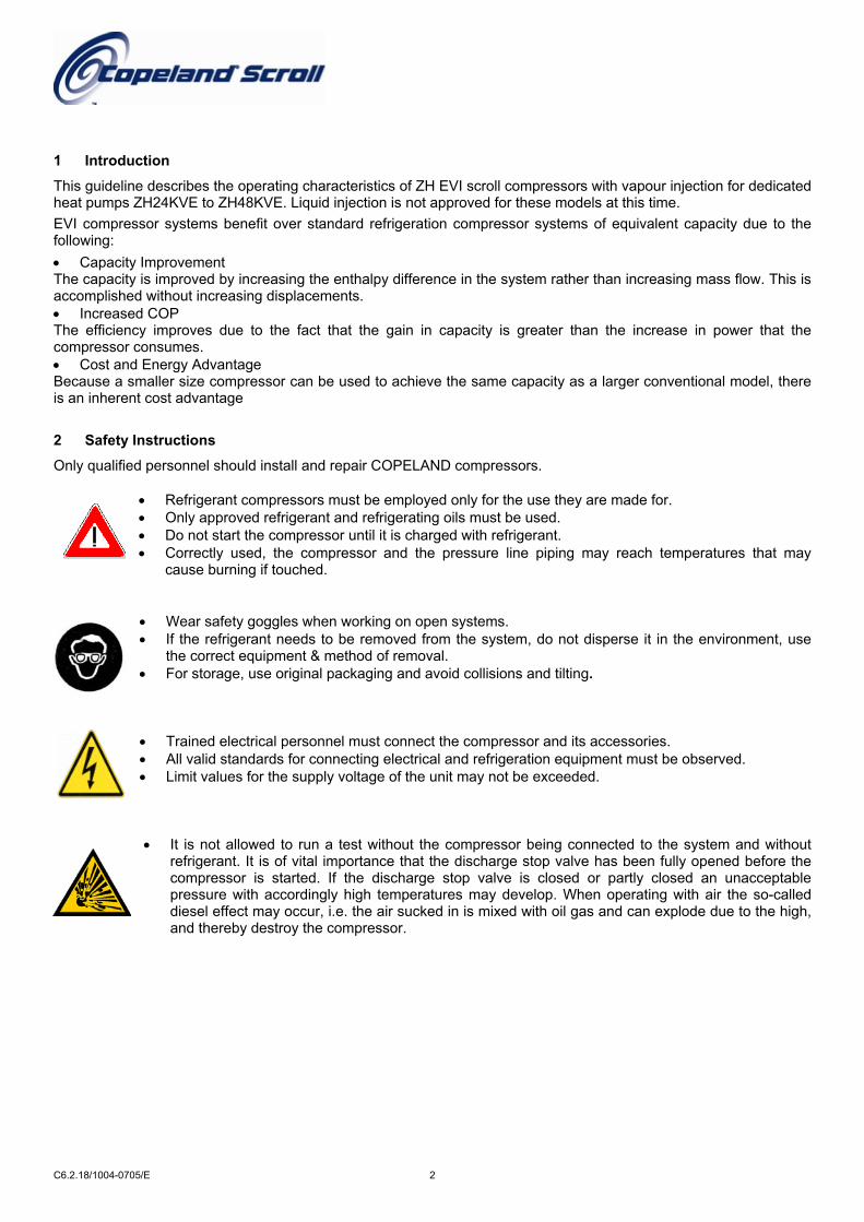
1 Introduction
This guideline describes the operating characteristics of ZH EVI scroll compressors with vapour injection for dedicated heat pumps ZH24KVE to ZH48KVE. Liquid injection is not approved for these models at this time. EVI compressor systems benefit over standard refrigeration compressor systems of equivalent capacity due to the following: • Capacity Improvement The capacity is improved by increasing the enthalpy difference in the system rather than increasing mass flow. This is accomplished without increasing displacements. • Increased COP The efficiency improves due to the fact that the gain in capacity is greater than the increase in power that the compressor consumes. • Cost and Energy Advantage Because a smaller size compressor can be used to achieve the same capacity as a larger conventional model, there is an inherent cost advantage
2 Safety Instructions
Only qualified personnel should install and repair COPELAND compressors.
• Refrigerant compressors must be employed only for the use they are made for.
C6.2.18/1004-0705/E 2
• Only approved refrigerant and refrigerating oils must be used. • Do not start the compressor until it is charged with refrigerant. • Correctly used, the compressor and the pressure line piping may reach temperatures that may
cause burning if touched.
• Wear safety goggles when working on open systems. • If the refrigerant needs to be removed from the system, do not disperse it in the environment, use
the correct equipment & method of removal. • For storage, use original packaging and avoid collisions and tilting.
• Trained electrical personnel must connect the compressor and its accessories. • All valid standards for connecting electrical and refrigeration equipment must be observed. • Limit values for the supply voltage of the unit may not be exceeded.
• It is not allowed to run a test without the compressor being connected to the system and without refrigerant. It is of vital importance that the discharge stop valve has been fully opened before the compressor is started. If the discharge stop valve is closed or partly closed an unacceptable pressure with accordingly high temperatures may develop. When operating with air the so-called diesel effect may occur, i.e. the air sucked in is mixed with oil gas and can explode due to the high, and thereby destroy the compressor.
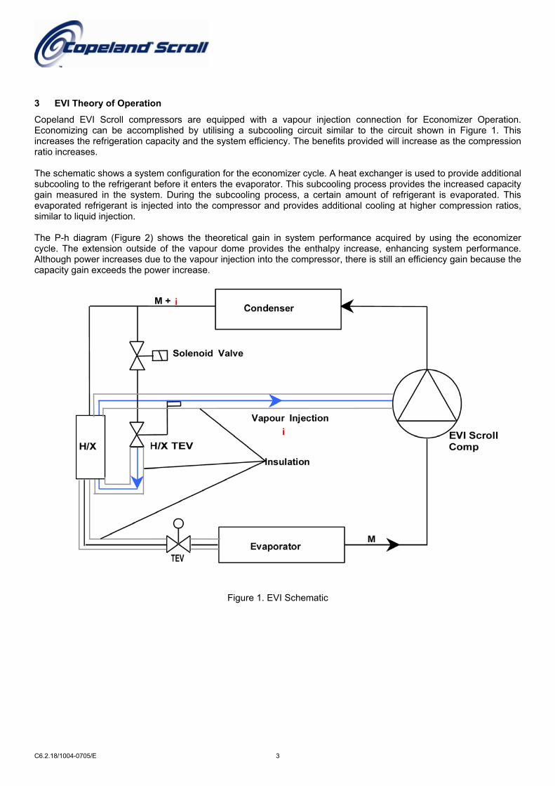
3 EVI Theory of Operation
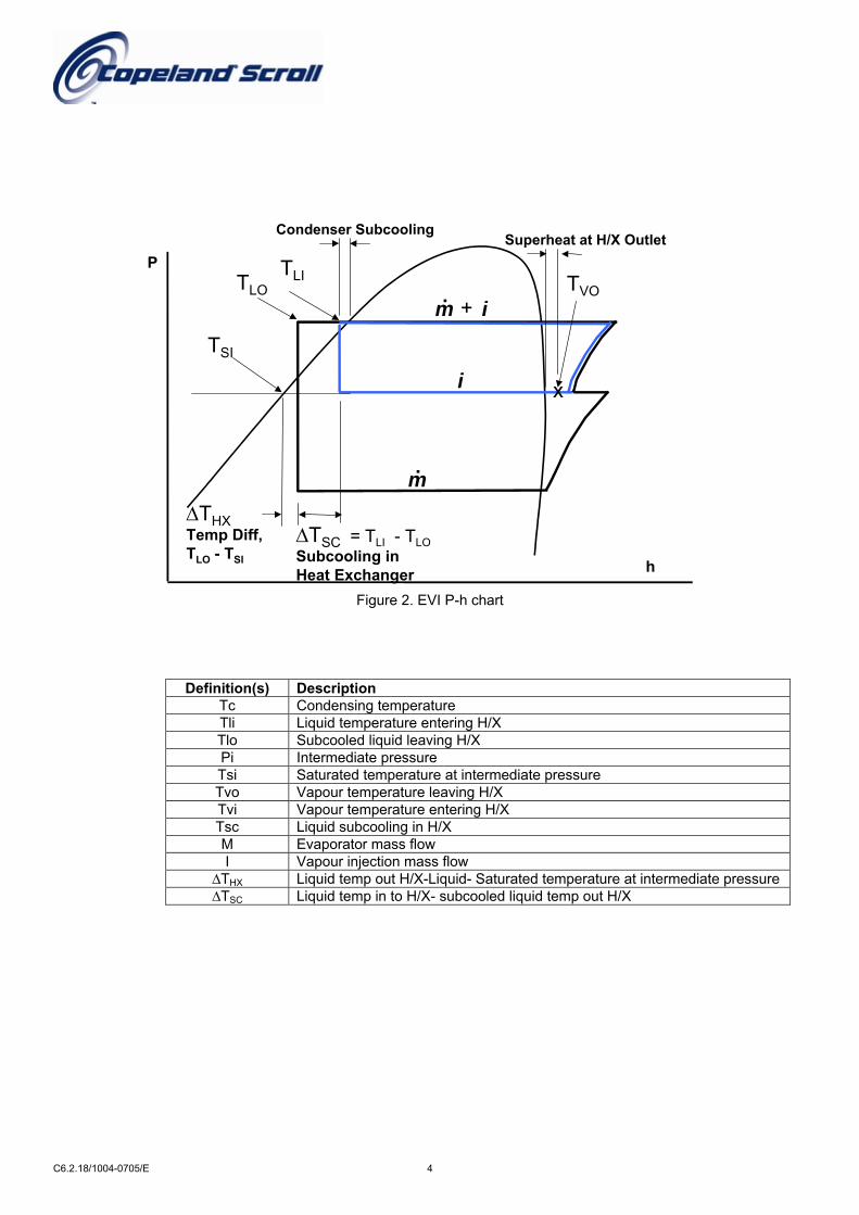
Copeland EVI Scroll compressors are equipped with a vapour injection connection for Economizer Operation. Economizing can be accomplished by utilising a subcooling circuit similar to the circuit shown in Figure 1. This increases the refrigeration capacity and the system efficiency. The benefits provided will increase as the compression ratio increases. The schematic shows a system configuration for the economizer cycle. A heat exchanger is used to provide additional subcooling to the refrigerant before it enters the evaporator. This subcooling process provides the increased capacity gain measured in the system. During the subcooling process, a certain amount of refrigerant is evaporated. This evaporated refrigerant is injected into the compressor and provides additional cooling at higher compression ratios, similar to liquid injection. The P-h diagram (Figure 2) shows the theoretical gain in system performance acquired by using the economizer cycle. The extension outside of the vapour dome provides the enthalpy increase, enhancing system performance. Although power increases due to the vapour injection into the compressor, there is still an efficiency gain because the capacity gain exceeds the power increase.
Figure 1. EVI Schematic
C6.2.18/1004-0705/E 3
P
h
m.
i
im. +
∆TSC = TLI - TLOSubcooling inHeat Exchanger
TLI
TSI
TLO
x
TVO
∆THXTemp Diff,TLO - TSI
Superheat at H/X Outlet Condenser Subcooling
Figure 2. EVI P-h chart
Definition(s) Description Tc Condensing temperature Tli Liquid temperature entering H/X Tlo Subcooled liquid leaving H/X Pi Intermediate pressure Tsi Saturated temperature at intermediate pressure Tvo Vapour temperature leaving H/X Tvi Vapour temperature entering H/X Tsc Liquid subcooling in H/X M Evaporator mass flow I Vapour injection mass flow
∆THX Liquid temp out H/X-Liquid- Saturated temperature at intermediate pressure ∆TSC Liquid temp in to H/X- subcooled liquid temp out H/X
C6.2.18/1004-0705/E 4

4 Nomenclature
The model numbers of Copeland Scroll™ compressors have been designed to include a coded nominal capacity at ARI operating conditions in BTU/h at 60 Hz without vapour injection All refrigeration scroll compressors are charged with ester oil, which is indicated by the letter “E”.
Model Designation Z H 48K V E - T W D - 5 26
1 2 3 4 5 6 7 1- Z = Compressor family: Z = Scroll 2- H = Dedicated heat pump compressor 3- Nominal capacity [kW] @ 50 Hz and –7°C Evaporating/ 50°C condensing temperatures 4 - Vapour injection for EVI operation 5 - POE Oil 6 - Motor version 7 - Bill of Material
5 Qualified Refrigerant
R407C has been qualified for the EVI scroll compressors for dedicated heat pumps.
6 Application Envelope
R407C Mid-point
Cond temp °C
Evaporating temp °C
Figure 3. Application envelope of EVI compressors
C6.2.18/1004-0705/E 5
7 System Configuration
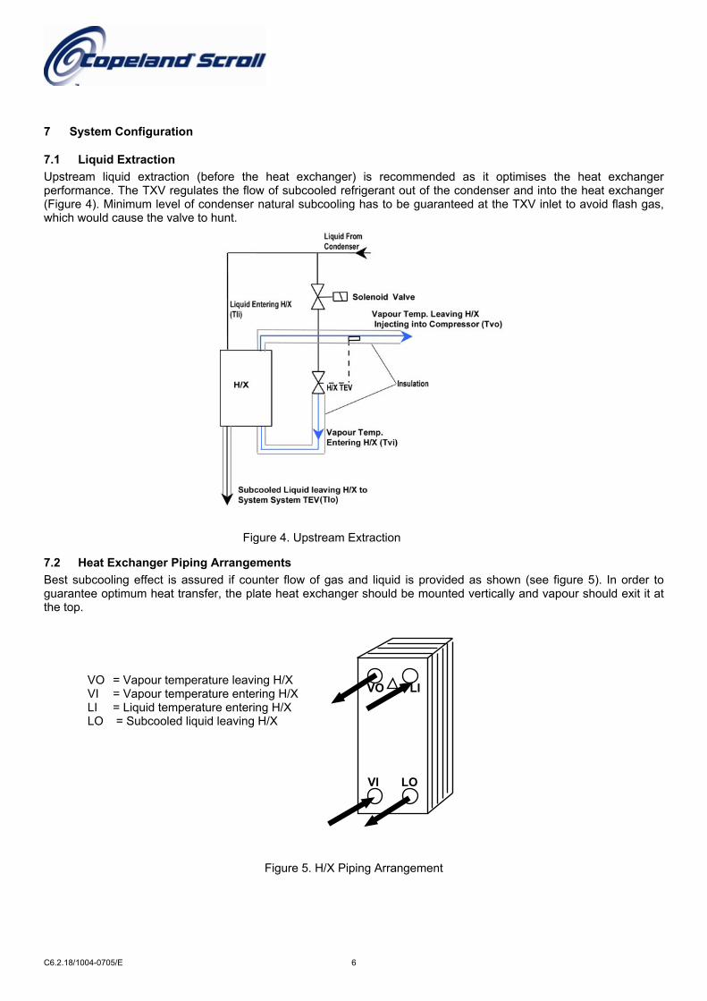
7.1 Liquid Extraction Upstream liquid extraction (before the heat exchanger) is recommended as it optimises the heat exchanger performance. The TXV regulates the flow of subcooled refrigerant out of the condenser and into the heat exchanger (Figure 4). Minimum level of condenser natural subcooling has to be guaranteed at the TXV inlet to avoid flash gas, which would cause the valve to hunt.
7.2 Heat Exchanger Piping ArranBest subcooling effect is assured if guarantee optimum heat transfer, thethe top.
VO = Vapour temperature leVI = Vapour temperature eLI = Liquid temperature enLO = Subcooled liquid leav
C6.2.18/1004-0705/E
Figure 4. Upstream Extraction
gements counter flow of gas and liquid is provided as shown (see figure 5). In order to plate heat exchanger should be mounted vertically and vapour should exit it at
VI
VO LI
LO
aving H/X ntering H/X tering H/X ing H/X
Figure 5. H/X Piping Arrangement
6

8 System Design Guidelines
The following sections discuss system design guidelines for the EVI product. Please use Copeland Selection Software SELECT, where all parameters are given for selecting a single heat exchanger. The Copeland Selection Software can be downloaded from www.eCopeland.comT. The key parameter in determining the proper heat exchanger size is the Saturated Injection Temperature (Tsi). The Tsi has been determined through extensive testing. This value can vary for each compressor and should be obtained from SELECT. After determining the Tsi, a 5K condenser natural subcooling, 5 K heat exchanger ∆THX and 5 K heat exchanger superheat are targeted. This is done to optimise system performance while maintaining system reliability and functionality at the same time. Once these parameters are known, the heat exchanger capacity (kW) can be determined, which gives the required heat exchanger size. (See Figure 6 below)
Figure 6. Heat Exchanger Details
C6.2.18/1004-0705/E 7

8.1 Heat Exchanger sizing using Select Figure 7 is an extract form SELECT which gives details of Economiser/heat exchanger load (kW) saturated intermediate temperature (Tsi) and sub-cooled liquid out of heat exchanger.
4K Natural Subcooling in Condenser
***
* Tsi temperature
** Tlo Liquid temperature leaving the heat exchanger
Figure 7. Details on EVI performance given by SELECT software. Heat exchangers should be sized for nominal operating conditions with adequate design margin to allow for the entire range of system operation.
8.2 Liquid and vapour injection line sizing The liquid line from the heat exchanger to the evaporator should be insulated and kept as short as possible in order to maximise the subcooling effect. The vapour injection line from the heat exchanger to the compressor should be 5/8” and kept as short as possible in order to minimise pressure drop loss.
C6.2.18/1004-0705/E 8

8.3 Heat exchanger expansion device The heat exchanger expansion device should be designed for maximum load while taking into account partial load conditions.
8.4 Solenoid valve A liquid line solenoid valve is required to prevent migration of refrigerant to the compressor when it is switched off. For multiple compressor application, a solenoid valve in the vapour injection line of each individual compressor is required. Each solenoid valve has to be energised in parallel to the compressor contactor. In the case of a single compressor application, the solenoid valve could be placed either on the liquid line before the heat exchanger TXV or on the vapour injection line to the compressor. For cost reasons, it is advisable to have the solenoid valve on the liquid side entering the heat exchanger expansion device.
9 Lubrication
The oil level should be maintained at mid-point of the sight glass. If an oil regulator is being used the level should be set within the top half of the sight glass. The compressor is supplied with an initial charge of polyolester (POE) lubricant. In the field the oil level could be topped up with Mobil EAL Arctic 22 CC. The recharge values can be taken from Copeland Selection Software. The compressors must be operated with these specific oils only. Under no circumstances are ester oils to be mixed with mineral oil and/or alkyl benzene when used with chlorine-free refrigerants. Although there is no flexible mounting of the internal compressor parts, the number of start/stop cycles should be limited to 10 per hour. A high cycling rate will pump oil into the system and may lead to lubrication failure. Oil leaves the compressor at start-up regardless of the low oil carry over of the Copeland Scroll. The short running time is insufficient to return the oil to the compressor and possibly results in a lack of lubricant. It must be considered that the entire system will be coated with oil to some extent. Oil viscosity changes with temperature. System gas velocity changes depending on temperature and load. In low load conditions gas velocity may not be high enough to return oil to the compressor. System piping should be designed to return oil under all operating conditions. For proper lubrication the minimum differential between bottom shell (tb) and evaporating (te) temperatures should be carefully observed as laid out in. On the other hand, the maximum bottom shell temperature should never exceed 93°C, measured close to the bottom center of the compressor.
Figure 8. Minimum bottom shell temperature (tb) One characteristic of POE is that it is far more hygroscopic than mineral oil (Figure 9). Only brief exposure to ambient air is needed for POE to absorb sufficient moisture to make it unacceptable for use in a refrigeration system. Since POE retains moisture chemically it is not possible to completely remove it through the use of vacuum. Compressors supplied by Copeland contain oil with a low moisture content, and this may rise during the system assembling process. Therefore it is recommended that a properly sized filter-drier is installed in all POE systems. This will maintain the moisture level in the oil to less than 50 ppm. If oil is charged into a system it is recommended to charge systems with POE containing no more than 50 ppm moisture content. If the moisture content of the oil in a refrigeration system reaches unacceptable high levels, corrosion and copper plating may occur.
C6.2.18/1004-0705/E 9

The system should be evacuated down to 0.3 mbar or lower. If there is uncertainty, as to the moisture content in the system, an oil sample should be taken and tested for moisture. Sight glass/moisture indicators currently available can be used with the HFC refrigerants and lubricants; however, the moisture indicator will just show the moisture contents of the refrigerant. The actual moisture level of POE would be higher than the sight glass specifies. This is a result of the high hygroscopicity of the POE oil. Oil samples would have to be taken from the system and analyzed to determine the actual moisture content of the lubricant.
Figure 9. Absorption of moisture in ester oil in comparison to mineral oil in [ppm] by weight at 25°C and 50% relative humidity. h = hours.
10 Accumulators
An accumulator is normally not required in dedicated heat pump applications. Durability is ensured by the Copeland Scroll’s inherent ability to handle liquid refrigerant in flooded start and defrost cycle operation. However, large volumes of liquid refrigerant which repeatedly flood back to the compressor during normal off cycles or excessive liquid refrigerant floodback during steady operation can dilute the oil in any compressor to the point where bearings become inadequately lubricated and wear may occur. If an accumulator is fitted, and there is no crankcase heater, it should be piped to allow free liquid drainage during the off cycle as shown in Figure 10. Recommended tests are described in section 22 to 24.
Figure 10. Accumulator
11 Crankcase Heaters
No crankcase heater (CCH) is required when the system charge does not exceed 7.5 kg. A CCH is to prevent refrigerant migrating into the shell during standstill periods. It is recommended to fit a CCH if the compressor is located outside the building, the system charge is above the limits shown. For correct mounting location of a CCH please see Figure 11.
Figure 11. Crankcase heater location
C6.2.18/1004-0705/E 10
12 Screens
The use of screens finer than 30 x 30 mesh (0,6 mm2 openings) anywhere in the system is not recommended. Field experience has shown that finer mesh screens used to protect thermal expansion valves, capillary tubes, or accumulators could become temporarily or permanently plugged. Such blockage can result in compressor failure.
13 Pump down
To control refrigerant migration a pump down system could be used. The discharge check valve with refrigeration scroll compressor is designed for low leak back, and will allow the use of a pump down without the addition of an external check valve. If the compressor is stationary for prolonged periods, refrigerant could migrate into the compressor and therefore a crankcase heater must be installed. If constant cold air is drawn over the compressor, this could make the crankcase heater ineffective, and therefore a pump down system is recommended.
14 Discharge Temperature Protection
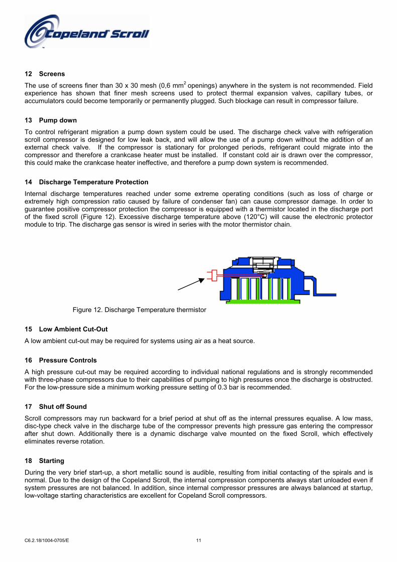
Internal discharge temperatures reached under some extreme operating conditions (such as loss of charge or extremely high compression ratio caused by failure of condenser fan) can cause compressor damage. In order to guarantee positive compressor protection the compressor is equipped with a thermistor located in the discharge port of the fixed scroll (Figure 12). Excessive discharge temperature above (120°C) will cause the electronic protector module to trip. The discharge gas sensor is wired in series with the motor thermistor chain.
Figure 12. Discharge Temperature thermistor
15 Low Ambient Cut-Out
A low ambient cut-out may be required for systems using air as a heat source.
16 Pressure Controls
A high pressure cut-out may be required according to individual national regulations and is strongly recommended with three-phase compressors due to their capabilities of pumping to high pressures once the discharge is obstructed. For the low-pressure side a minimum working pressure setting of 0.3 bar is recommended.
17 Shut off Sound
Scroll compressors may run backward for a brief period at shut off as the internal pressures equalise. A low mass, disc-type check valve in the discharge tube of the compressor prevents high pressure gas entering the compressor after shut down. Additionally there is a dynamic discharge valve mounted on the fixed Scroll, which effectively eliminates reverse rotation.
18 Starting
During the very brief start-up, a short metallic sound is audible, resulting from initial contacting of the spirals and is normal. Due to the design of the Copeland Scroll, the internal compression components always start unloaded even if system pressures are not balanced. In addition, since internal compressor pressures are always balanced at startup, low-voltage starting characteristics are excellent for Copeland Scroll compressors.
C6.2.18/1004-0705/E 11
19 Deep-Vacuum Operation
The danger of pulling deep vacuums is avoided due to an internal low vacuum protection which prevents the scrolls pumping (unloads) when the pressure ratio exceeds approximately 20:1. In order to avoid nuisance trips, it is recommended to set the low-pressure control as described in Section 16 above.
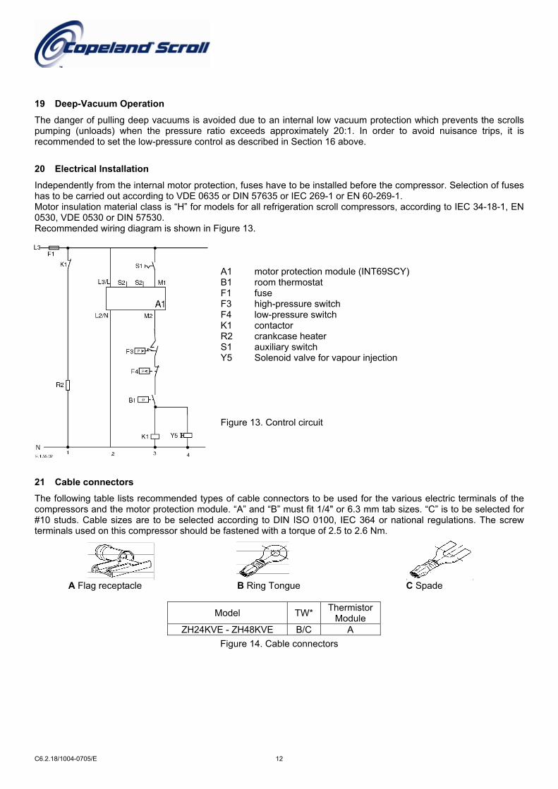
20 Electrical Installation
Independently from the internal motor protection, fuses have to be installed before the compressor. Selection of fuses has to be carried out according to VDE 0635 or DIN 57635 or IEC 269-1 or EN 60-269-1. Motor insulation material class is “H” for models for all refrigeration scroll compressors, according to IEC 34-18-1, EN 0530, VDE 0530 or DIN 57530. Recommended wiring diagram is shown in Figure 13.
A1 motor protection module (INT69SCY) B1 room thermostat F1 fuse F3 high-pressure switch F4 low-pressure switch K1 contactor R2 crankcase heater S1 auxiliary switch Y5 Solenoid valve for vapour injection Figure 13. Control circuit
21 Cable connectors
The following table lists recommended types of cable connectors to be used for the various electric terminals of the compressors and the motor protection module. “A” and “B” must fit 1/4" or 6.3 mm tab sizes. “C” is to be selected for #10 studs. Cable sizes are to be selected according to DIN ISO 0100, IEC 364 or national regulations. The screw terminals used on this compressor should be fastened with a torque of 2.5 to 2.6 Nm.
A Flag receptacle B Ring Tongue C Spade
Model TW* Thermistor Module
ZH24KVE - ZH48KVE B/C A Figure 14. Cable connectors
C6.2.18/1004-0705/E 12

22 Electronic Motor Protection
Protector Specifications: Type: Carel Voltage: 24 V AC; 230 V AC,120/240 V AC Control Rating: 60 VA, 25 A Inrush 300/375 VA 25/15 A Inrush Normal PTC resistance: 250 to 1000 Ohms Trip resistance: >4500 Ohm +/- 20% Reset resistance: <2750 Ohms Module time out: 30 minutes +/- 5 minutes Low Voltage Sensing: None Phase Monitor: No Figure 15. Thermistor Resistance Curve
The electronic motor protection system as used in all ZH24KVE ... ZH48KVE models is identified by a “W” as the centre letter in the motor code. This system utilises the temperature dependent resistance of thermistors (also called PTC resistances) to read the winding temperature. A chain of four thermistors connected in series is embedded in the motor windings so that the temperature of the thermistors can follow the winding temperature with little inertia. An electronic module is required to process the resistance values and trip a control relay depending on the thermistor resistance. The characteristic gradient of a thermistor resistance curve is shown in Figure 15. The resistance curve can be designed for different operating points, the nominal response temperature (NAT), e.g. 80 °C, 130 °C, 140 °C and must comply with the tolerances laid out in the standard DIN 44081. Module For protection in case of blocked rotor one thermistor for each phase is embedded in the winding heads on the upper (suction gas) side of the compressor motor (NAT 100 °C). A fourth thermistor is located in a winding head at the lower end of the motor (NAT 140 °C). A fifth sensor is located in the discharge port of the fixed scroll to control discharge gas superheat (NAT 140 °C). The entire chain is internally led to the fusite from where it is connected to the module connections S1 and S2 (see Figure 16). When any resistance of the thermistor chain reaches the tripping value, the module interrupts the control line and causes the compressor to switch off. After the thermistor has cooled sufficiently, its resistance drops to the reset value but the module itself resets after a time delay of 30 minutes and restarts the compressor.
L1/T1 neutral connection L2/T2 line voltage connection S1, S2 thermistor chain connection M1, M2 control circuit connection
Figure 16. Wiring of the Motor Protection Module
23 Protector Functional Check and Failure Detection
Prior to start-up of the compressor a functional check shall be carried out: - Switch off power! - Disconnect one terminal either S1 or S2 of the electronic module. If the compressor is now switched on, the motor
should not start. - Switch off power. - Reconnect the disconnected thermistor line. If the compressor is now switched on the motor must start.
C6.2.18/1004-0705/E 13

C6.2.18/1004-0705/E 14
Protector Fault Diagnosis: If the motor does not start-up during the functional check, this indicates a disturbance in operation: - Switch off power. - Check the connection of the thermistor leads in the terminal box and at the protection module for possible loose
connections and check the connection cable for possible breakage. - The resistance of the thermistor chain shall be measured in a cold condition i.e. after the motor has sufficiently
cooled down. Caution: Use maximum measuring voltage of 3 V! In doing so, the thermistor leads at terminals S1 and S2 of the module shall be disconnected and measured between the leads. Resistance must be between 150 and 1250 ohms. If the thermistor chain has a higher resistance (2750 Ohms or greater) the motor temperature is still too high and it has to be allowed to cool. If the resistor is 0 Ohms, the compressor has to be exchanged due to shorted sensor circuit. ∞ Ohms indicates an open sensor circuit and the compressor has to be replaced. If no defect is located in the thermistor chain or there is no loose contact or conductor breakage, the module shall be checked. Then the control connections at M1 and M2 have to be removed (Caution! Switch off voltage supply first!) and check the switching conditions by an ohm-meter or signal buzzer: - short-cut the already disconnected thermistor contactors S1 and S2 and switch on the voltage supply; the relay
must switch; connection established between contactors M1 and M2 - remove the jumper between S1 and S2, the relay must switch off; no connection between contactors M1 and M2 - short-cut the contactors S1 and S2 again, the relay remains switched off; no connection between contactors M1
and M2 - switch off the voltage supply for approximately 4 sec and switch it on again, the relay must switch on now;
connection between contactors M1 and M2 If one of the above conditions is not met, the module is defective and has to be exchanged. Note: The power should be switched off between the tests, in order to avoid short circuits and accidental touching of contacts. The function of the module should be tested each time the fuse in the control circuit breaks the power supply. This makes sure that the contacts did not stick.
24 High Potential Testing
Copeland subjects all motor compressors to a high voltage test after final assembly. This is carried out according to IEC-34-1. Since high voltage tests lead to premature aging of the winding insulation we do not recommend additional tests of that nature. They may also be carried out with new machines only. If it has to be done for any reason disconnect all electronic devices (e.g. motor protection module, fan speed control, etc.) prior to testing. The test voltage of 1000 V plus twice the nominal voltage is applied for 1 - 4 seconds between motor winding (each one of the phases) and the compressor shell: The maximum leak current limit is approximately 10 mA. Repeated tests have to be performed at lower voltages. Caution: Do not carry out high voltage or insulation tests if the compressor housing is under vacuum. Copeland Scroll compressors are configured with the motor down and the pumping components at the top of the shell. As a result, the motor can be immersed in refrigerant to a greater extent than hermetic reciprocating compressors when liquid refrigerant is present in the shell. In this respect, the scroll is more like semi-hermetics (which have horizontal motors partially submerged in oil and refrigerant). When Copeland Scroll compressors are high potential tested with liquid refrigerant in the shell they can show higher levels of leakage current than compressors with the motor on top because of the higher electrical conductivity of liquid refrigerant than refrigerant vapour and oil. However, this phenomenon can occur with any compressor when the motor is immersed in refrigerant. The levels of current leakage do not present any safety issue. To lower the current leakage reading the system should be operated for a brief period of time to redistribute the refrigerant to a more normal configuration and the system high potential tested again.

C6.2.18/1004-0705/E 15
25 Compressor Functional Check
It is not desirable to perform functional compressor tests where the compressor is turned on with the suction service valve closed to check how low the compressor will pull suction pressure. Rather, the following diagnostic procedure should be used to evaluate whether the Copeland Scroll compressor is functioning properly. 1. Proper voltage to the unit should be verified. 2. The normal checks of motor winding continuity and short to ground should be made to determine if the internal
overload motor protector of a ZH13KVE or ZH18KVE model has opened or if an internal short to ground has developed. If the protector has opened, the compressor must be allowed to cool sufficiently to allow it to reset.
3. Proper indoor and outdoor fan/blower operation should be verified. 4. With service gauges connected to suction and discharge pressure fittings, turn on the compressor. If suction
pressure falls below normal levels the system is either low on charge or there is a flow blockage in the system. 5. If suction pressure does not drop and discharge pressure does not rise to normal levels, reverse any two of the
compressor power leads and reapply power to make sure compressor was not wired to run in reverse direction. If pressures still do not move to normal values, the compressor is faulty.
26 Excessive Liquid Floodback
The following tests are for those Air/Water system configurations and charge levels, which need special testing to verify exemption from the need of an accumulator.
27 Continuous Floodback
To test for excessive continuous liquid refrigerant floodback, it is necessary to operate the system in a test room at conditions where steady state floodback may occur (low ambient air/water heating). Thermocouples should be attached to the suction and discharge lines of the compressor (approximately 150 mm from the shell) and insulated. If the system is designed to be field charged it should be overcharged by 15 % in this test to simulate overcharging commonly found in field installations. The system should be operated at an indoor temperature of 20°C and outdoor temperature extremes (-18°C or lower) which produce floodback conditions. The compressor suction and discharge pressures and temperatures should be recorded. The system should be allowed to frost up for several hours (disabling the defrost control and spraying water on the outdoor coil may be necessary) to cause the saturated suction temperature to fall to -30°C or below. The compressor sump temperature must remain above the saturated suction temperature as determined from Figure 8 or design changes must be made to reduce the amount of floodback. If an accumulator is used an oil return orifice size of 1,4 mm is recommended.
28 Repeated Floodback during Defrost
For systems using hot gas bypass defrost, and having refrigerant charge levels above the limits given in Section 11 it may be necessary to fit an accumulator to trap a certain amount of the returning liquid. A good indication of liquid return can be low sump temperatures. Obtain a sample compressor with a side sight tube to measure liquid level in the compressor. Set the system up in a configuration with the indoor unit elevated approximately 1 m above the outdoor unit with approximately 7 m of connecting tubing with no traps between the indoor and outdoor units. If the system is designed to be field charged, the system should be overcharged by 15% in this test to simulate overcharging commonly found in field installations. Record the height of the liquid in the compressor during each cycle, any protector trips, or any compressor stalls during each test. Review all test results with Copeland Application Engineering to determine if an accumulator is required for the application.

29 Installation
Four vibration absorber grommets are supplied with each compressor (see Figure. 17). They dampen the start-up surge of the compressor and prevent sounds and vibrations from being transmitted to the compressor base during operation to a large extent. The metal sleeve inside is intended as a guide to hold the grommet in place. It is not designed as a load-bearing member, and excessive torquing can crush the sleeve. Its inner diameter is approximately 8.5 mm to fit e.g. an M8 screw. The mounting torque should be 13 ± 1 Nm. It is critically important that the grommet is not compressed. A clearance space of approximately 2 mm between the bottom of the washer and the top of the grommet spacer is recommended (see Figure. 17)
Z.9.28.00
2 mm
In Operation
Figure 17. Mounting parts
30 Service
Copeland Scroll compressors have copper plated steel suction and discharge tubes. These tubes are far more robust and less prone to leaks than copper tubes used on other compressors. Due to the different thermal properties of steel and copper, brazing procedures may have to be changed from those commonly used. For brazing of the tubes see figure 18 and the following procedures. Since the discharge stub contains a check valve, care must be taken not to overheat it as well as to prevent brazing material from flowing into it.
31 New Installations
The copper-coated steel tubes on scroll compressors can be brazed in approximately the same manner as any
copper tube. Recommended brazing materials: Any silfos material is recommended, preferably with a minimum of 5% silver. However, 0% silver is acceptable.
Be sure tube fitting inner diameter and tube outer diameter are clean prior to assembly. Using a double-tipped torch apply heat in area As the tube approaches brazing temperature, move the torch flame to area 2. Heat area 2 until braze temperature is attained, moving the torch up and down and rotating around the tube as
necessary to heat the tube evenly. Add braze material to the joint while moving the torch around the joint to flow braze material around the circumference.
After the braze-material flows around the joint, move the torch to heat area 3. This will draw the braze-material down into the joint. The time spent heating area 3 should be minimal.
As with any brazed joint, overheating may be detrimental to the final result.
Figure 18. Suction tube brazing
C6.2.18/1004-0705/E 16

32 Field Service
To disconnect:
Heat joint areas 2 and 3 slowly and uniformly until the braze material softens and the tube can be pulled out of the fitting.
To reconnect:
Recommended brazing-materials: Silfos with minimum 5% silver or silver braze used on other compressors. Due to the different thermal properties of steel and copper, brazing procedures may have to be changed from those commonly used. For brazing of the tubes see figure 18 and the following procedures. Since the discharge stub contains a check valve, care must be taken not to overheat it as well as to prevent brazing material to flow into it.
33 Suction Line Noise and Vibration
Copeland Scroll compressors inherently have low sound and vibration characteristics. However, in some respects, the sound and vibration characteristics differ from reciprocating compressors and, in rare instances, could result in unexpected sound complaints. One difference is that the vibration characteristic of the Scroll compressor, although low, includes two very close frequencies, one of which is normally isolated from the shell by the suspension of an internally suspended compressor. These frequencies, which are present in all compressors, may result in a low level “beat” frequency that can be detected as noise coming along the suction line into a house under some conditions. Elimination of the “beat” can be achieved by attenuating either of the contributing frequencies. This is easily done by using one of the common combinations of design configuration described below. A second difference of the Copeland Scroll compressor is that under some conditions the normal starting motion of the compressor can transmit an “impact” noise along the suction line. This phenomenon, like the one described above, also results from the lack of internal suspension, and can be easily avoided by using standard line isolation techniques as described below. Recommended configuration (Figure 19): Tubing configuration: small shock loop Service valve: “angled valve” fastened to unit/wall Suction muffler: not required
Alternative configuration: Tubing configuration: small shock loop Service valve: “straight-through” valve fastened to unit/wall Suction muffler: may be required
Figure 19. Suction tube design
C6.2.18/1004-0705/E 17

C6.2.18/1004-0705/E 18
34 Shell Temperature
Under rare circumstances caused by failure of system components such as the condenser or evaporator fan, or loss of charge, and depending on the type of expansion control, the top shell and discharge line can briefly but repeatedly reach temperatures above 177°C as the compressor cycles on its internal protection devices. Care must be taken to ensure that wiring or other materials, which could be damaged by these temperatures, do not come into contact with the shell.
35 System Charging Procedure
Rapid charging on only the suction side of a single-phase Scroll equipped system or condensing unit can occasionally result in a temporary no-start condition for the compressor. The reason for this is that if the flanks of the spirals happen to be in a sealed position, rapid pressurization of the low side without opposing high side pressure can cause the spirals to seal axially. As a result, until the pressures eventually equalize, the spirals can be held tightly together, preventing rotation. The best way to avoid this situation is to charge on both the high and the low side simultaneously at a rate which does not result in axial loading of the spirals. The maximum charging rate can be determined through simple tests.
36 Unbrazing System Components
Caution! Before opening a system, it is important to remove all refrigerants from both the high and low side. If the refrigerant charge is removed from a scroll-equipped unit by bleeding the high side only, it is possible for the scrolls to seal preventing pressure equalisation through the compressor. This may leave the low side shell and suction line tubing pressurised. If a brazing torch is then applied to the low side while the low side shell and suction line contains pressure, the pressurised refrigerant and oil mixture could ignite when it escapes and contacts the brazing flame. To prevent this occurrence, it is important to check both the high and low side with manifold gauges before unbrazing. Instructions should be provided in appropriate product literature and assembly (line repair) areas. If compressor removal is required, the compressor should be cut out of system rather than unbrazed.
37 Compressor Replacement
In the case of a motor burn, the majority of contaminated oil will be removed with the compressor. The rest of the oil is cleaned through use of suction and liquid line filter dryers. A 100% activated alumina suction filter drier is recommended but must be removed after 72 hours. It is highly recommended that the suction accumulator be replaced if the system contains one. This is because the accumulator oil return orifice or screen may be plugged with debris or may become plugged shortly after a compressor failure. This will result in starvation of oil to the replacement compressor and a second failure. When a single compressor or tandem is exchanged in the field, a major portion of the oil may still be in the system. While this may not affect the reliability of the replacement compressor, the extra oil will add to rotor drag and increase power usage. See Section for Rotalock valve, flange fittings, sight glass, and mounting bolt torque’s values.

C6.
2.18
/ 10
04-0
705/
E
Copeland Marketing & Sales - 27, Rue des Trois Bourdons - B 4840 Welkenraedt, Belgium
Tel. +32 (0) 87 305411 - Fax +32 (0) 87 305506 - internet: www.ecopeland.com - email: [email protected]
The Emerson logo is a trademark and service mark of Emerson Electric Co. Copeland Corporation is a division of Emerson Electric Co. Copeland is a registered trademark and Copeland Scroll is a trademark of Copeland Corporation. All other trademarks are the property of their respective owners. Information contained in this brochure is subject to change without notification.
© 2005 Copeland
Benelux Eastern Europe, Turkey & IranDeltakade 7 27, Rue des Trois BourdonsNL-5928 PX Venlo B-4840 WelkenraedtTel. +31 (0) 77 324 0234 Tel. +32 (0) 87 305 061Fax +31 (0) 77 324 0235 Fax +32 (0) 87 305 506
Deutschland/Österreich & Schweiz PolandSenefelder Straße 3 11A, KonstruktorskaD-63477 Maintal P-02-673 WarszawaTel. +49 (0)6109 6059 0 Tel. +48 225 458 9205Fax +49 (0)6109 6059 40 Fax +48 225 458 9255
France/Greece & Maghreb Russia & CIS8, Allee Du Moulin Berger Malaya Trubetskaya, 8-11th FloorF-69130 Ecully RUS-119881 MoscowTel. +33 (0)4 78668570 Tel. +7 095 232 94 72Fax +33 (0)4 78668571 Fax +7 095 232 03 56
Italia Middle East & AfricaVia Ramazzotti, 26 PO Box 26382, R/A 8, FD-2I-21047 Saronno (va) Jebel Ali, Dubai - UAETel. +39 02 961781 Tel. +9714 883 2828Fax +39 02 96178888 Fax +9714 883 2848
España & Portugal
Sweden/Denmark/Norway & Finland
Diputacion, 238 AT.8
Östbergavägen 4, P.O.Box 10
E-08007 Barcelona
S-59021 Väderstad
Tel. +34 93 4123752
Tel. +46 (0) 142 70520
Fax +34 93 4124215
Fax +46 (0) 142 70521
UK & IrelandColthrop WayGB- Thatcham, Berkshire - RG19 4 NQTel. +44 (0)1635 87 6161Fax +44 (0)1635 877111
Asia/Pacific10/F, Pioneer Building, 213 Wai Yip Street,Kwun Tong, Kowloon - Hong KongTel. +852 28 66 31 08Fax +852 25 20 62 27
Latin America7975 North West 154Th Street - Suite 300Miami Lakes, FL, 33016 - USATel. +1 305 818 8880Fax +1 305 818 8888