Embed Size (px)
Citation preview
GB/07.10 – Ident No. 796 493 1
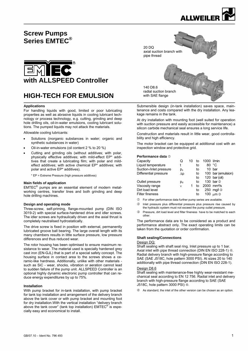
Screw Pumps Series EMTEC®
with ALLSPEED Controller HIGH-TECH FOR EMULSION
Applications For handling liquids with good, limited or poor lubricating properties as well as abrasive liquids in cooling lubricant tech-nology or process technology, e.g. cutting, grinding and deep hole drilling oils, oil-in-water emulsions, cooling lubricant solu-tions. The pumped liquids may not attack the materials.
Allowable cooling lubricants:
Solutions (inorganic substances in water; organic and synthetic substances in water)
Oil-in-water emulsions (oil content 2 % to 20 %)
Cutting and grinding oils (without additives; with polar, physically effective additives; with mild-effect EP* addi-tives that create a lubricating film; with polar and mild-effect additives; with active chemical EP* additives; with polar and active EP* additives).
* EP = Extreme Pressure (high pressure additives)
Main fields of application EMTEC® pumps are an essential element of modern metal-working centres, transfer lines and both grinding and deep hole drilling machines.
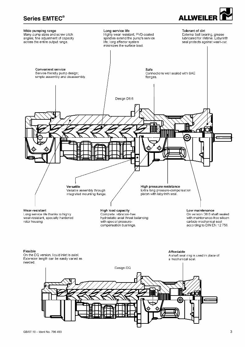
Design and operating mode Three-screw, self-priming, flange-mounted pump (DIN ISO 3019-2) with special surface-hardened drive and idler screws. The idler screws are hydraulically driven and the axial thrust is completely neutralised hydrostatically.
The drive screw is fixed in position with external, permanently lubricated groove ball bearing. The large overall length with its many chambers results in little surface pressure, low pressure differences and thus reduced wear.
The rotor housing has been optimised to ensure maximum re-sistance to wear. The material used is specially hardened grey cast iron (EN-GJL) that is part of a special safety concept. The housing surface in contact area to the screws shows a ce-ramic-like hardness. Additionally, unlike with other materials - such as SiC - wear, shocks, vibration or aeration cannot lead to sudden failure of the pump unit. ALLSPEED Controller is an optional highly dynamic electronic pump controller that can re-duce energy expenditures by up to 75%.
Installation With pump bracket for in-tank installation, with pump bracket for tank top installation and arrangement of the delivery branch above the tank cover or with pump bracket and mounting foot for dry installation.With the vertical installation “delivery branch above the tank cover” (tank top installation) EMTEC® is espe-cially easy and economical to install.
Submersible design (in-tank installation) saves space, main-tenance and costs compared with the dry installation. Any lea-kage remains in the tank.
At dry installation with mounting foot (well suited for operation with suction pressure and easily accessible for maintenance) a silicon carbide mechanical seal ensures a long service life.
Construction and materials result in little wear, good controlla-bility and high efficiency.
The motor bracket can be equipped at additional cost with an inspection window and protective grid.
Performance data Capacity Q 10 to 1000 I/min Liquid temperature t to 80 ° C Suction-/inlet pressure ps to 10 bar Differential pressure p to 100 bar (emulsion) to 120 bar (oil) Outlet pressure pd to 130 bar Viscosity range 1 to 2000 mm²/s Dirt load level to 250 mg/l Filter fineness to 100 m
For other performance data further pump series are available.
Inlet pressure plus differential pressure plus pressure rise caused by the hydraulic system must not exceed the pump outlet pressure.
Pressure, dirt load level and filter fineness have to be matched to each other.
The performance data are to be considered as a product and performance abstract only. The exact operating limits can be taken from the quotation or order confirmation.
Shaft sealing/Connections Design DQ: Shaft sealing with shaft seal ring. Inlet pressure up to 1 bar. Axial inlet with pipe thread connection (DIN EN ISO 228-1) . Radial delivery branch with high-pressure flange according to SAE (SAE J518C, hole pattern 3000 PSI). At sizes 20 to 140 additionally with pipe thread connection (DIN EN ISO 228-1).
Design D8.6 Shaft sealing with maintenance-free highly wear-resistant me-chanical seal according to EN 12 756. Radial inlet and delivery branch with high-pressure flange according to SAE (SAE J518C, hole pattern 3000 PSI) .
As standard, the inlet of the other version can be chosen as an option.
20 DQ axial suction branch with pipe thread
140 D8.6 radial suction branch with SAE flange
Series EMTEC®
2 GB/07.10 – Ident No. 796 493
Overload protection The pump has no pressure relief valve. Thus the overload pro-tection must be provided in the control system or as a pipeline valve.
Abbreviation
EMTEC - A 80 R 46 D 8.6 W110221
Series
Development status
Size
Direction of screw pitch R = right
Screw pitch angle (degree)
Design feature
Shaft sealing/Connections
Material code
theoret. capacity at 1450 1/min and 46° screw pitch angle
D = external antifriction bearing, shaft seal unheated, uncooled
shaft seal/connections
Abbreviation Type
Q shaft seal ring/axial inlet, pipe thread 8.6 mechanical seal/radial inlet, SAE
in standard
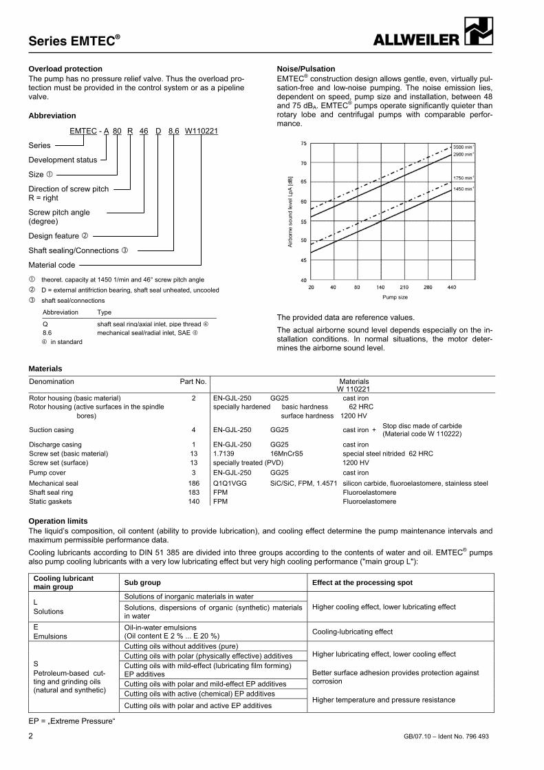
Noise/Pulsation EMTEC® construction design allows gentle, even, virtually pul-sation-free and low-noise pumping. The noise emission lies, dependent on speed, pump size and installation, between 48 and 75 dBA. EMTEC® pumps operate significantly quieter than rotary lobe and centrifugal pumps with comparable perfor-mance.
The provided data are reference values.
The actual airborne sound level depends especially on the in-stallation conditions. In normal situations, the motor deter-mines the airborne sound level.
Materials
Denomination Part No. Materials W 110221Rotor housing (basic material) 2 EN-GJL-250 GG25 cast ironRotor housing (active surfaces in the spindle specially hardened basic hardness 62 HRC bores) surface hardness 1200 HV
Suction casing 4 EN-GJL-250 GG25 cast iron +Stop disc made of carbide (Material code W 110222)
Discharge casing 1 EN-GJL-250 GG25 cast iron Screw set (basic material) 13 1.7139 16MnCrS5 special steel nitrided 62 HRC Screw set (surface) 13 specially treated (PVD) 1200 HV
Pump cover 3 EN-GJL-250 GG25 cast iron
Mechanical seal 186 Q1Q1VGG SiC/SiC, FPM, 1.4571 silicon carbide, fluoroelastomere, stainless steel Shaft seal ring 183 FPM Fluoroelastomere Static gaskets 140 FPM Fluoroelastomere
Operation limits The liquid’s composition, oil content (ability to provide lubrication), and cooling effect determine the pump maintenance intervals and maximum permissible performance data.
Cooling lubricants according to DIN 51 385 are divided into three groups according to the contents of water and oil. EMTEC® pumps also pump cooling lubricants with a very low lubricating effect but very high cooling performance ("main group L"):
Cooling lubricant main group
Sub group Effect at the processing spot
L Solutions
Solutions of inorganic materials in water
Higher cooling effect, lower lubricating effect Solutions, dispersions of organic (synthetic) materials in water
E Emulsions
Oil-in-water emulsions (Oil content E 2 % ... E 20 %)
Cooling-lubricating effect
S Petroleum-based cut-ting and grinding oils (natural and synthetic)
Cutting oils without additives (pure) Higher lubricating effect, lower cooling effect Better surface adhesion provides protection against corrosion Higher temperature and pressure resistance
Cutting oils with polar (physically effective) additives Cutting oils with mild-effect (lubricating film forming) EP additives Cutting oils with polar and mild-effect EP additives Cutting oils with active (chemical) EP additives
Cutting oils with polar and active EP additives
EP = „Extreme Pressure“
Series EMTEC®
GB/07.10 – Ident No. 796 493 3
ALLSPEED Controller
4 GB/07.10 – Ident No. 796 493
Benefits and usage When equipped with the ALLSPEED Controller, the EMTEC system can reduce energy costs by up to 75%. This is made possible by a highly dynamic electronic pump controller with adaptive control. This also provides a high-pressure supply of cooling lubricant without the need for valves, which greatly re-duces the costs associated with pump, motor, valve, and cool-ing components. Elimination of valves also helps avoid capaci-ty losses and pressure surges. In addition, the “Smart” con-cept provides for automatic monitoring of operational limits.
Modes of operation - Single-screw mode: The pump system supplies exactly
one screw of the machine tool. Speed and pressure go from 0 to their operating points very quickly. Pump sizes 20 and 40 are suitable for this mode of operation.
- Multi-spindle mode (all sizes): In this case, one pump sys-tem simultaneously supplies several spindle. Pump pres-sure is fully adjustable and constant. Capacity adapts dy-namically to current requirements (pressure control valve not necessary). The pump operates with low pressure pulsation; pulsation remains below 20% even when the capacity varies greatly (up to 30% of total capacity).
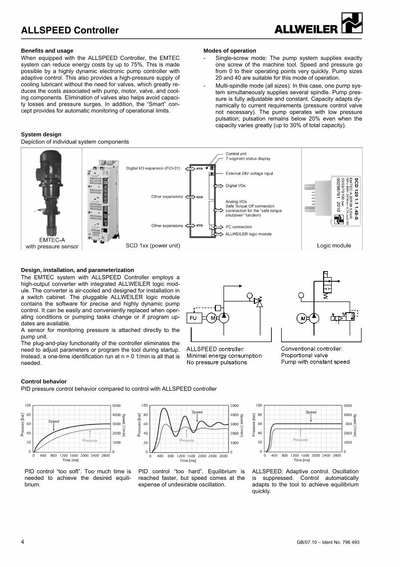
System design Depiction of individual system components
Design, installation, and parameterization The EMTEC system with ALLSPEED Controller employs a high-output converter with integrated ALLWEILER logic mod-ule. The converter is air-cooled and designed for installation in a switch cabinet. The pluggable ALLWEILER logic module contains the software for precise and highly dynamic pump control. It can be easily and conveniently replaced when oper-ating conditions or pumping tasks change or if program up-dates are available. A sensor for monitoring pressure is attached directly to the pump unit. The plug-and-play functionality of the controller eliminates the need to adjust parameters or program the tool during startup. Instead, a one-time identification run at n = 0 1/min is all that is needed.
Control behavior PID pressure control behavior compared to control with ALLSPEED controller
PID control “too soft”. Too much time is needed to achieve the desired equili-brium.
PID control “too hard”. Equilibrium is reached faster, but speed comes at the expense of undesirable oscillation.
ALLSPEED: Adaptive control. Oscillation is suppressed. Control automatically adapts to the tool to achieve equilibrium quickly.
ALLSPEED Controller
GB/07.10 – Ident No. 796 493 5
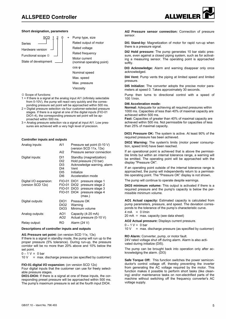
Short designation, parameters
SCD 1 2 0 +
Series
Hardware version
Functional scope
State of development Scope of functions: 1 = If there is a signal at the analog input AI1 (infinitely selectable
from 0-10V), the pump will react very quickly and the corres-ponding pressure set point will be approached within 500 ms.
2 = Digital pressure selection via four customer-selected pressure stages. If there is a signal at one of the digital inputs (FIO-01 DIO1-4), the corresponding pressure set point will be ap-proached within 500 ms.
3 = Analog pressure selection via a signal at input AI1. Low pres-sures are achieved with a very high level of precision.
Controller inputs and outputs
Analog inputs: AI1 Pressure set point (0-10 V) (version SCD 11x, 13x) AI2 Pressure sensor connection
Digital inputs: DI1 Standby (magnetization) DI2 Hold pressure (10 bar) DI3 Acknowledge warning, alarm DI4 Vent DI5 Initialize DI6 Acceleration mode
Digital I/O expansion: FIO-01 DIO1 pressure stage 1 (version SCD 12x) FIO-01 DIO2 pressure stage 2 FIO-01 DIO3 pressure stage 3 FIO-01 DIO4 pressure stage 4 (max.)
Digital outputs: DIO1 Pressure OK DIO2 Warning DIO3 Minimum volume
Analog outputs: AO1 Capacity (4-20 mA) AO2 Actual pressure (0-10 V)
Relay output: RO Alarm (24 V)
Descriptions of controller inputs and outputs
AI1 Pressure set point: (on version SCD 11x, 13x) If there is a signal in standby mode, the pump will run up to the proper pressure (5% tolerance). During run-up, the pressure corridor will be no more than 20% above and 10% below the set point. 0 – 1 V = 0 bar 10 V = max. discharge pressure (as specified by customer)
FIO-01 digital I/O expansion: (on version SCD 12x) Four digital inputs that the customer can use for freely select-able pressure stages. DIO1-DIO4: If there is a signal at one of these inputs, the cor-responding preset pressure will be approached within 500 ms. The pump's maximum pressure is set at the fourth input DIO4.
AI2 Pressure sensor connection: Connection of pressure sensor.
DI1 Stand-by: Magnetization of motor for rapid run-up when there is a pressure signal.
DI2 Hold pressure: The pump generates 10 bar static pres-sure, even against a closed piping system, such as for activat-ing a measuring sensor. The operating point is approached softly.
DI3 Acknowledge: Alarm and warning disappear only once acknowledged.
DI4 Vent: Pump vents the piping at limited speed and limited pressure.
DI5 Initialize: The converter adopts the precise motor para-meters at speed 0. Takes approximately 30 seconds.
Pump then turns to directional control with a speed of 100 1/min.
DI6 Acceleration mode: Normal: Adequate for achieving all required pressures within 1000 ms. Capacities of less than 40% of maximal capacity are achieved within 500 ms. Fast: Capacities of greater than 40% of maximal capacity are achieved within 500 ms. Not permissible for capacities of less than 25% of maximal capacity.
DIO1 Pressure OK: The system is active. At least 90% of the required pressure has been achieved.
DIO2 Warning: The system's limits (motor power consump-tion, speed limit) have been reached.
If an operational point is achieved that is above the permissi-ble limits but within an internal tolerance range, a warning will be emitted. The operating point will be approached with the display "Pressure OK".
If an operating point outside of the internal tolerance range is approached, the pump will independently return to a permissi-ble operating point. The "Pressure OK” display is not shown.
The pump will continue to operate despite warnings.
DIO3 minimum volume: This output is activated if there is a required pressure and the pump's capacity is below the per-missible minimum volume.
AO1 Actual capacity: Estimated capacity is calculated from pump parameters, pressure, and speed. The deviation corres-ponds to the tolerance of the pump’s characteristic curve. 4 mA = 0 l/min 20 mA = max. capacity (see data sheet)
AO2 Actual pressure: Displays current pressure. 0 – 1 V = 0 bar 10 V = max. discharge pressure (as specified by customer)
RO Alarm: Converter, pump, or motor fault. 24V rated voltage shut off during alarm. Alarm is also acti-vated during initialize (DI5).
The pump can be brought back into operation only after ac-knowledging the alarm. (DI3)
Safe Torque Off: This function switches the power semicon-ductor's control voltage off, thereby preventing the inverter from generating the AC voltage required by the motor. This function makes it possible to perform short tasks (like clean-ing) and/or maintenance tasks on non-electrified parts of the machine without switching off the frequency converter's AC voltage supply.
Pump type, size
Rated output of motor
Rated voltage
Rated frequency
Motor current (nominal operating point)
cos φ
Nominal speed
Max. speed
Max. pressure
Viscosity
ALLSPEED Controller
6 GB/07.10 – Ident No. 796 493
Mandatory conditions of the cooling lubrication system for installation of the ALLSPEED controller
Volume meters can make the system sluggish: Please remove volume meters with hydraulic sluggishness (such as measurement turbines) or place them in front of the pump. The ALLSPEED controller provides capacity measure-ment via the AO1 analog output.
Improperly switched stop valves can result in warning and alarm conditions in the controller: When using stop valves, maintain adequate amounts of time for starting and shutting down the pump - 100 ms when start-ing and 1 to 2 seconds when shutting down. A stop valve is not necessary when running without backpres-sure. If no pressure is required, the ALLSPEED controller switches the EMTEC to speed and capacity of zero.
Existing pressure regulation valves or pressure relief valves may control against the system: The ALLSPEED controller does not need a valve to control pressure. An existing pressure regulation valve or pressure relief valve can be used as a safety valve and should be set at least 10% higher than the maximum control pressure.
A large number of sharp bends in pipe fittings will lead to pressure losses in the line: High pressure losses should be avoided. Otherwise, the con-trol parameter for the pressure at the ALLSPEED controller may have to be increased to compensate for the loss. Volume measurement through the analog output AO1 gives you the ability to set the required pressure in the most optimal way possible with the desired capacity.
Improperly laid pipes and excessive lengths can allow air to penetrate the pipe when idled: A large volume of air in the pipe can extend the start-up and shut-down times of the system. Under normal conditions, the ALLSPEED controller automati-cally compensates for disturbances caused by air inclusions. If higher pressure pulsations occur during start-up, you can vent the pipe in advance by activating the DI4 input. When operating with multiple consumers, very strong vo-lume fluctuations can lead to pressure pulsations: Please ensure that the switching time (especially when switch-ing off consumers during operation) is at least 100 ms. Ca-pacity fluctuations should not exceed 30% of the maximum vo-lume. Under these conditions, the ALLSPEED controller can adjust the required capacity with a maximum pressure pulsation of 20%. Faster switching times and higher volume jumps can cause the safety valve to trigger briefly.
Very small capacities can cause the ALLSPEED controller to automatically reset the pressure: In this way the controller protects the pump from overloads at slow speeds while simultaneously ensuring that cooling lubri-cant continues to be pumped. The minimum volume limits are documented in the characte-ristic curves (starting on page 15) and in the selection pro-gram. If the volume falls below the minimum amount, the controller will activate the DIO3 digital output. If needed, it can be used to trigger a bypass valve.
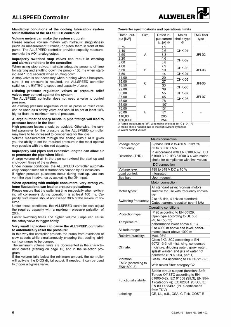
Converter specifications and operational limits
Rated out-put [kW]
Size Rated in-put current I1N [A]
Mains choke type
EMC filter type
0,75
A
1,9 CHK-01
JFI-02 1,10 2,6 1,50 3,3 2,20 4,6 CHK-02 3,00 5,8 4,00
B 7,9 CHK-03
JFI-03 5,50 10 7,50 14 CHK-04 11,00
C
20 CHK-05 JFI-05 15,00 27
18,50 33 CHK-06 22,00 39 30,00
D 55 CHK-07
JFI-07 37,00 65 CHK-08 45,00 78 55,00
E
107
- - 75,00 131 90,00 171 110,00 205 160,00 254 Rated input current (eff.) with mains choke at 40 °C (104 °F) Mains choke needed due to the high system dynamics Water-cooled version
Mains connection
Voltage range: 3-phase 380 V to 480 V +10/15% Frequency: 50 to 60 Hz ± 5%
Distortion (THD): In accordance with EN 61000-3-2, IEC 61000-3-12, IEC 61000-3-4 with mains choke for compliance with limit values
DC connection
Voltage level: 485 to 648 V DC ± 10 % Load control: Integrated Bus bar: Upon request
Motor connection
Motor types: All standard asynchronous motors suitable for use with frequency conver-ter
Switching frequency:2 to 16 kHz, 4 kHz as standard; Output current reduction over 4 kHz
Operating conditions
Protection type: IP 20 according to EN 60529; Open type according to UL 508
Temperature: -10 to +55 °C; performance lower above 40 °C
Altitude range: 0 to 4000 m above sea level, perfor-mance lower above 1000 m
Relative humidity: Max. 95%
Climate:
Class 3K3, 3C2 according to EN 60721-3-3, oil mist, icing, condensed moisture, dripping water, spray water, splash waster, and jets of water not permitted (EN 60204, part 1)
Vibration: Class 3M4 according to EN 60721-3-3 EMC: (according to EN61800-3)
With mains filter: category C2
Functional stability:
Stable torque support (function: Safe Torque-Off STO according to EN 61800-5-2); IEC 61508 (SIL3); EN 954-1 (category 4); IEC 62061 (SILCL 3); EN ISO 13849-1 (PL e certification from TÜV)
Labeling: CE, UL, cUL, CSA, C-Tick, GOST R
ALLSPEED Controller
GB/07.10 – Ident No. 796 493 7
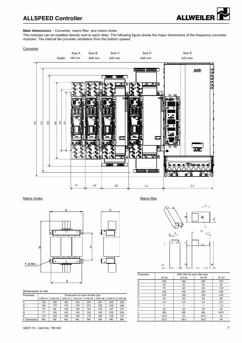
Main dimensions – Converter, mains filter, and mains choke The modules can be installed directly next to each other. The following figure shows the major dimensions of the frequency converter modules. The internal fan provides ventilation from the bottom upward.
Converter
Mains choke Mains filter
Dimensions in mm Parameter Dimensions for each throttle type CHK-01 CHK-02 CHK-03 CHK-04 CHK-05 CHK-06 CHK-07 CHK-08
A 120 150 150 150 207 207 249 249 B 146 175 175 175 272 326 326 346
C 79 86 100 100 154 154 167 167
D 77 105 105 105 193 193 235 235
E 114 148 148 148 118 169 125 147
F (Schraube) M5 M5 M5 M5 M6 M6 M6 M8
Parameter EMC filter for each filter type JFI-02 JFI-03 JFI-05 JFI-07
A 250 250 250 270 B 45 50 85 90
C 70 85 90 150
D 220 240 220 240
E 235 255 235 255
F 25 30 60 65
G 5,4 5,4 5,4 6,5
H 1 1 1 1,5
I 22 25 39 45
J M5 M5 M6 M10
K 22,5 25 42,5 45
L 29,5 39,5 26,5 64
248 mm 169 mm
Size E Size D Size C Size B
423 mm
Size A
Depth: 246 mm 248 mm
Series EMTEC®
8 GB/07.10 – Ident No. 796 493
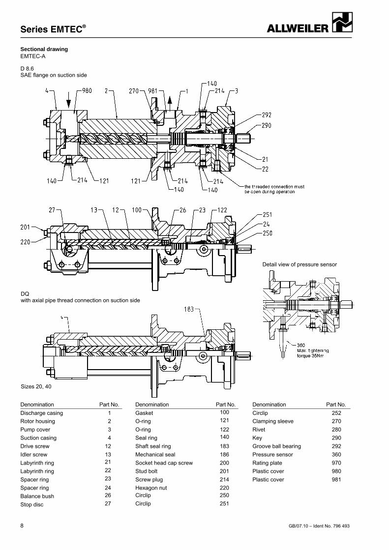
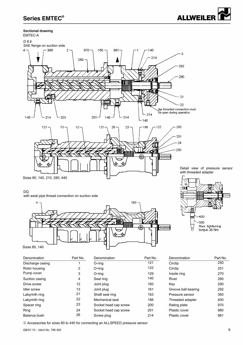
Sectional drawing EMTEC-A
Denomination Part No. Denomination Part No. Denomination Part No.
Discharge casing 1 Gasket 100 Circlip 252
Rotor housing 2 O-ring 121 Clamping sleeve 270
Pump cover 3 O-ring 122 Rivet 280
Suction casing 4 Seal ring 140 Key 290
Drive screw 12 Shaft seal ring 183 Groove ball bearing 292
Idler screw 13 Mechanical seal 186 Pressure sensor 360
Labyrinth ring 21 Socket head cap screw 200 Rating plate 970
Labyrinth ring 22 Stud bolt 201 Plastic cover 980
Spacer ring 23 Screw plug 214 Plastic cover 981
Spacer ring 24 Hexagon nut 220
Balance bush 26 Circlip 250
Stop disc 27 Circlip 251
D 8.6 SAE flange on suction side
DQ with axial pipe thread connection on suction side
Sizes 20, 40
Detail view of pressure sensor
Series EMTEC®
GB/07.10 – Ident No. 796 493 9
Sectional drawing EMTEC-A
Denomination Part No. Denomination Part No. Denomination Part No.
Discharge casing 1 O-ring 121 Circlip 250
Rotor housing 2 O-ring 122 Circlip 251 Pump cover 3 O-ring 129 Inside ring 270
Suction casing 4 Seal ring 140 Rivet 280
Drive screw 12 Joint plug 160 Key 290
Idler screw 13 Joint plug 161 Groove ball bearing 292
Labyrinth ring 21 Shaft seal ring 183 Pressure sensor 360
Labyrinth ring 22 Mechanical seal 186 Threaded adapter 400
Spacer ring 23 Socket head cap screw 200 Rating plate 970
Ring 24 Socket head cap screw 201 Plastic cover 980
Balance bush 26 Screw plug 214 Plastic cover 981
D 8.6 SAE flange on suction side
Sizes 80, 140, 210, 280, 440
Sizes 80, 140
Detail view of pressure sensorwith threaded adapter
DQ with axial pipe thread connection on suction side
Accessories for sizes 80 to 440 for connecting an ALLSPEED pressure sensor
Series EMTEC®
10 GB/07.10 – Ident No. 796 493
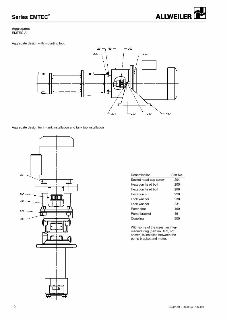
Aggregates EMTEC-A
Aggregate design with mounting foot
Aggregate design for in-tank installation and tank top installation
Denomination Part No.
Socket head cap screw 204
Hexagon head bolt 205
Hexagon head bolt 206
Hexagon nut 220
Lock washer 230
Lock washer 231
Pump foot 460
Pump bracket 461
Coupling 900
With some of the sizes, an inter-mediate ring (part no. 462, not shown) is installed between the pump bracket and motor.
Series EMTEC®
GB/07.10 – Ident No. 796 493 11
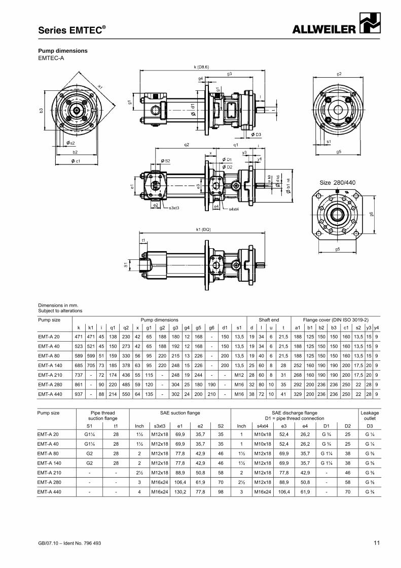
Pump dimensions EMTEC-A
Dimensions in mm. Subject to alterations
Pump size Pump dimensions Shaft end Flange cover (DIN ISO 3019-2)
k k1 i q1 q2 x g1 g2 g3 g4 g5 g6 d1 s1 d l u t a1 b1 b2 b3 c1 s2 y3 y4
EMT-A 20 471 471 45 138 230 42 65 188 180 12 168 - 150 13,5 19 34 6 21,5 188 125 150 150 160 13,5 15 9
EMT-A 40 523 521 45 150 273 42 65 188 192 12 168 - 150 13,5 19 34 6 21,5 188 125 150 150 160 13,5 15 9
EMT-A 80 589 599 51 159 330 56 95 220 215 13 226 - 200 13,5 19 40 6 21,5 188 125 150 150 160 13,5 15 9
EMT-A 140 685 705 73 185 378 63 95 220 248 15 226 - 200 13,5 25 60 8 28 252 160 190 190 200 17,5 20 9
EMT-A 210 737 - 72 174 436 55 115 - 248 19 244 - - M12 28 60 8 31 268 160 190 190 200 17,5 20 9
EMT-A 280 861 - 90 220 485 59 120 - 304 25 180 190 - M16 32 80 10 35 292 200 236 236 250 22 28 9
EMT-A 440 937 - 88 214 550 64 135 - 302 24 200 210 - M16 38 72 10 41 329 200 236 236 250 22 28 9
Pump size Pipe thread suction flange
SAE suction flange SAE discharge flange D1 = pipe thread connection
Leakage outlet
S1 t1 Inch s3xt3 e1 e2 S2 Inch s4xt4 e3 e4 D1 D2 D3
EMT-A 20 G1¼ 28 1½ M12x18 69,9 35,7 35 1 M10x18 52,4 26,2 G ¾ 25 G ¼
EMT-A 40 G1¼ 28 1½ M12x18 69,9 35,7 35 1 M10x18 52,4 26,2 G ¾ 25 G ¼
EMT-A 80 G2 28 2 M12x18 77,8 42,9 46 1½ M12x18 69,9 35,7 G 1¼ 38 G ⅜
EMT-A 140 G2 28 2 M12x18 77,8 42,9 46 1½ M12x18 69,9 35,7 G 1¼ 38 G ⅜
EMT-A 210 - - 2½ M12x18 88,9 50,8 58 2 M12x18 77,8 42,9 - 46 G ⅜
EMT-A 280 - - 3 M16x24 106,4 61,9 70 2½ M12x18 88,9 50,8 - 58 G ⅜
EMT-A 440 - - 4 M16x24 130,2 77,8 98 3 M16x24 106,4 61,9 - 70 G ⅜
Series EMTEC®
12 GB/07.10 – Ident No. 796 493
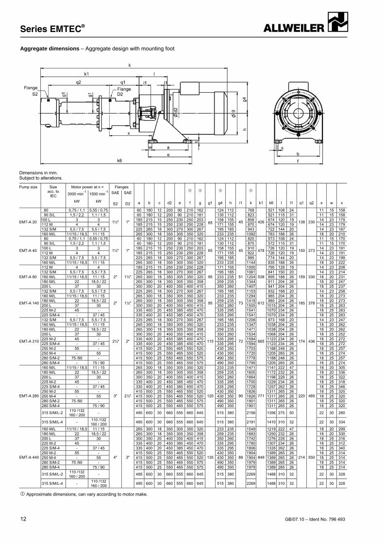
Aggregate dimensions – Aggregate design with mounting foot
Dimensions in mm. Subject to alterations.
Pump size Size acc. to
IEC
Motor power at n = Flanges
a b c d2 e
g1
h i1
k1 k6 l l1 q1 q2 s w x
3000 min-1
kW
1500 min-1
kW
SAE SAE
f g g4 k S2 D2
EMT-A 20
80 0,75 / 1,1 0,55 / 0,75
1½″ 1″
60 180 12 200 90 210 162
65
124 112
45
768
426
521 108 24
138 230
11 15 15890 S/L 1,5 / 2,2 1,1 / 1,5 60 180 12 200 90 210 181 130 112 823 521 115 31 11 15 158
100 L 3 3 185 215 15 250 230 250 203 158 155 858 674 120 19 14 23 179112 M 4 4 185 215 15 250 230 250 228 171 155 870 674 120 19 14 23 179132 S/M 5,5 / 7,5 5,5 / 7,5 225 265 18 300 270 300 267 195 185 943 722 144 20 14 23 187160 M/L 11/15 / 18,5 11 / 15 265 300 18 350 305 350 320 233 235 1092 783 188 26 18 20 210
EMT-A 40
80 0,75 / 1,1 0,55 / 0,75
1½″ 1″
60 180 12 200 90 210 162
65
124 112
45
820
478
573 108 24
150 273
11 15 17090 S/L 1,5 / 2,2 1,1 / 1,5 60 180 12 200 90 210 181 130 112 875 572 115 31 11 15 170
100 L 3 3 185 215 15 250 230 250 203 158 155 910 726 120 19 14 23 191112 M 4 4 185 215 15 250 230 250 228 171 155 922 726 120 19 14 23 191132 S/M 5,5 / 7,5 5,5 / 7,5 225 265 18 300 270 300 267 195 185 995 774 144 20 14 23 199160 M/L 11/15 / 18,5 11 / 15 265 300 18 350 305 350 320 233 235 1144 835 188 26 18 20 222
EMT-A 80
112 M 4 4
2″ 1½″
185 215 15 250 230 250 228
95
171 155
51
1000
538
795 128 19
159 330
14 23 208132 S/M 5,5 / 7,5 5,5 / 7,5 225 265 18 300 270 300 267 195 185 1061 841 150 20 14 23 214160 M/L 11/15 / 18,5 11 / 15 265 300 18 350 305 350 320 233 235 1204 895 188 26 18 20 231180 M/L 22 18,5 / 22 265 300 18 350 305 350 358 259 235 1344 911 204 26 18 20 247200 L 37 30 300 350 20 400 350 400 415 350 260 1407 941 204 26 18 25 237
EMT-A 140
132 S/M 5,5 / 7,5 5,5 / 7,5
2″ 1½″
225 265 18 300 270 300 267
95
195 185
73
1153
612
932 168 20
185 378
14 23 258160 M/L 11/15 / 18,5 11 / 15 265 300 18 350 305 350 320 233 235 1294 985 204 26 18 20 273180 M/L 22 18,5 / 22 265 300 18 350 305 350 358 259 235 1418 985 204 26 18 20 273200 L 37 30 300 350 20 400 350 400 415 350 260 1505 1015 204 26 18 25 263225 M-2 45 - 335 400 20 450 385 450 470 335 295 1541 1070 234 26 18 25 283225 S/M-4 - 37 / 45 335 400 20 450 385 450 470 335 295 1541 1070 234 26 18 25 283
EMT-A 210
132 S/M 5,5 / 7,5 5,5 / 7,5
2½″ 2″
225 265 18 300 270 300 267
115
195 185
72
1206
665
973 168 20
174 436
14 23 247160 M/L 11/15 / 18,5 11 / 15 265 300 18 350 305 350 320 233 235 1347 1038 204 26 18 20 262180 M/L 22 18,5 / 22 265 300 18 350 305 350 358 259 235 1471 1038 204 26 18 20 262200 L 37 30 300 350 20 400 350 400 415 350 260 1534 1068 204 26 18 25 252225 M-2 45 - 335 400 20 450 385 450 470 335 295 1594 1123 234 26 18 25 272225 S/M-4 - 37 / 45 335 400 20 450 385 450 470 335 295 1594 1123 234 26 18 25 272250 M-2 55 - 415 500 25 550 465 550 520 430 350 1703 1188 248 26 18 25 257250 M-4 - 55 415 500 25 550 465 550 520 430 350 1720 1205 265 26 18 25 274280 S/M-2 75 /90 - 415 500 25 550 465 550 575 490 350 1778 1188 248 26 18 25 257280 S/M-4 - 75 / 90 415 500 25 550 465 550 575 490 350 1795 1205 265 26 18 25 274
EMT-A 280
160 M/L 11/15 / 18,5 11 / 15
3″ 2½″
265 300 18 350 305 350 320
120
233 235
90
1471
771
1141 222 47
220 485
18 20 305180 M/L 22 18,5 / 22 265 300 18 350 305 350 358 259 235 1605 1172 232 26 18 20 336200 L 37 30 300 350 20 400 350 400 415 350 260 1664 1198 228 26 18 25 322225 M-2 45 - 335 400 20 450 385 450 470 335 295 1700 1229 234 26 18 25 318225 S/M-4 - 37 / 45 335 400 20 450 385 450 470 335 295 1728 1257 262 26 18 25 346250 M-2 55 - 415 500 25 550 465 550 520 430 350 1826 1311 265 26 18 25 320250 M-4 - 55 415 500 25 550 465 550 520 430 350 1826 1311 265 26 18 25 320280 S/M-2 75 /90 - 415 500 25 550 465 550 575 490 350 1901 1311 265 26 18 25 320280 S/M-4 75 / 90 415 500 25 550 465 550 575 490 350 1901 1311 265 26 18 25 320
315 S/M/L-2 110 /132 160 / 200
- 495 600 30 660 555 660 645 515 380 2156 1356 275 50 22 30 280
315 S/M/L-4 - 110 /132 160 / 200
495 600 30 660 555 660 645 515 380 2191 1410 310 32 22 30 334
EMT-A 440
160 M/L 11/15 / 18,5 11 / 15
4″ 3″
265 300 18 350 305 350 320
135
233 235
88
1549
849
1219 222 47
214 550
18 20 299180 M/L 22 18,5 / 22 265 300 18 350 305 350 358 259 235 1683 1250 232 26 18 20 330200 L 37 30 300 350 20 400 350 400 415 350 260 1742 1276 228 26 18 25 316225 M-2 45 - 335 400 20 450 385 450 470 335 295 1780 1307 234 26 18 25 312225 S/M-4 - 37 / 45 335 400 20 450 385 450 470 335 295 1806 1335 262 26 18 25 340250 M-2 55 - 415 500 25 550 465 550 520 430 350 1904 1389 265 26 18 25 314250 M-4 - 55 415 500 25 550 465 550 520 430 350 1904 1389 265 26 18 25 314280 S/M-2 75 /90 - 415 500 25 550 465 550 575 490 350 1979 1389 265 26 18 25 314280 S/M-4 75 / 90 415 500 25 550 465 550 575 490 350 1979 1389 265 26 18 25 314
315 S/M/L-2 110 /132 160 / 200
- 495 600 30 660 555 660 645 515 380 2269 1488 310 32 22 30 328
315 S/M/L-4 - 110 /132 160 / 200
495 600 30 660 555 660 645 515 380 2269 1488 310 32 22 30 328
Approximate dimensions, can vary according to motor make.
Series EMTEC®
GB/07.10 – Ident No. 796 493 13
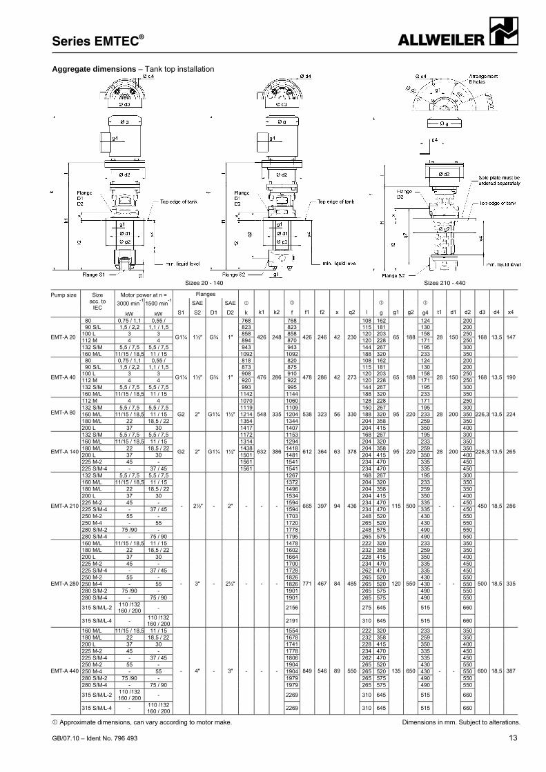
Aggregate dimensions – Tank top installation
Sizes 20 - 140 Sizes 210 - 440
Pump size
Size acc. to
IEC
Motor power at n = Flanges
k1 k2
f1 f2 x q2 l
g1 g2
t1 d1 d2 d3 d4 x4
3000 min-1
kW
1500 min-1
kW
SAE SAE
S1 S2 D1 D2 k f g g4
EMT-A 20
80 0,75 / 1,1 0,55 /
G1¼ 1½″ G¾ 1″
768
426 248
768
426 246 42 230
108 162
65 188
124
28 150
200
168 13,5 147
90 S/L 1,5 / 2,2 1,1 / 1,5 823 823 115 181 130 200100 L 3 3 858 858 120 203 158 250112 M 4 4 894 870 120 228 171 250132 S/M 5,5 / 7,5 5,5 / 7,5 943 943 144 267 195 300160 M/L 11/15 / 18,5 11 / 15 1092 1092 188 320 233 350
EMT-A 40
80 0,75 / 1,1 0,55 /
G1¼ 1½″ G¾ 1″
818
476 286
820
478 286 42 273
108 162
65 188
124
28 150
200
168 13,5 190
90 S/L 1,5 / 2,2 1,1 / 1,5 873 875 115 181 130 200100 L 3 3 908 910 120 203 158 250112 M 4 4 920 922 120 228 171 250132 S/M 5,5 / 7,5 5,5 / 7,5 993 995 144 267 195 300160 M/L 11/15 / 18,5 11 / 15 1142 1144 188 320 233 350
EMT-A 80
112 M 4 4
G2 2″ G1¼ 1½″
1070
548 335
1060
538 323 56 330
128 228
95 220
171
28 200
250
226,3 13,5 224132 S/M 5,5 / 7,5 5,5 / 7,5 1119 1109 150 267 195 300160 M/L 11/15 / 18,5 11 / 15 1214 1204 188 320 233 350180 M/L 22 18,5 / 22 1354 1344 204 358 259 350200 L 37 30 1417 1407 204 415 350 400
EMT-A 140
132 S/M 5,5 / 7,5 5,5 / 7,5
G2 2″ G1¼ 1½″
1172
632 386
1153
612 364 63 378
168 267
95 220
195
28 200
300
226,3 13,5 265
160 M/L 11/15 / 18,5 11 / 15 1314 1294 204 320 233 350180 M/L 22 18,5 / 22 1438 1418 204 358 259 350200 L 37 30 1501 1481 204 415 350 400225 M-2 45 - 1561 1541 234 470 335 450225 S/M-4 - 37 / 45 1561 1541 234 470 335 450
EMT-A 210
132 S/M 5,5 / 7,5 5,5 / 7,5
- 2½″ - 2″ - - -
1267
665 397 94 436
168 267
115 500
195
- -
300
450 18,5 286
160 M/L 11/15 / 18,5 11 / 15 1372 204 320 233 350180 M/L 22 18,5 / 22 1496 204 358 259 350200 L 37 30 1534 204 415 350 400225 M-2 45 - 1594 234 470 335 450225 S/M-4 - 37 / 45 1594 234 470 335 450250 M-2 55 - 1703 248 520 430 550250 M-4 - 55 1720 265 520 430 550280 S/M-2 75 /90 - 1778 248 575 490 550280 S/M-4 - 75 / 90 1795 265 575 490 550
EMT-A 280
160 M/L 11/15 / 18,5 11 / 15
- 3″ - 2½″ - - -
1478
771 467 84 485
222 320
120 550
233
- -
350
500 18,5 335
180 M/L 22 18,5 / 22 1602 232 358 259 350200 L 37 30 1664 228 415 350 400225 M-2 45 - 1700 234 470 335 450225 S/M-4 - 37 / 45 1728 262 470 335 450250 M-2 55 - 1826 265 520 430 550250 M-4 - 55 1826 265 520 430 550280 S/M-2 75 /90 - 1901 265 575 490 550280 S/M-4 - 75 / 90 1901 265 575 490 550
315 S/M/L-2 110 /132 160 / 200
- 2156 275 645 515 660
315 S/M/L-4 - 110 /132 160 / 200
2191 310 645 515 660
EMT-A 440
160 M/L 11/15 / 18,5 11 / 15
- 4″ - 3″ - - -
1554
849 546 89 550
222 320
135 650
233
- -
350
600 18,5 387
180 M/L 22 18,5 / 22 1678 232 358 259 350200 L 37 30 1741 228 415 350 400225 M-2 45 - 1778 234 470 335 450225 S/M-4 - 37 / 45 1806 262 470 335 450250 M-2 55 - 1904 265 520 430 550250 M-4 - 55 1904 265 520 430 550280 S/M-2 75 /90 - 1979 265 575 490 550280 S/M-4 - 75 / 90 1979 265 575 490 550
315 S/M/L-2 110 /132 160 / 200
- 2269 310 645 515 660
315 S/M/L-4 - 110 /132 160 / 200
2269 310 645 515 660
Approximate dimensions, can vary according to motor make. Dimensions in mm. Subject to alterations.
Series EMTEC®
14 GB/07.10 – Ident No. 796 493
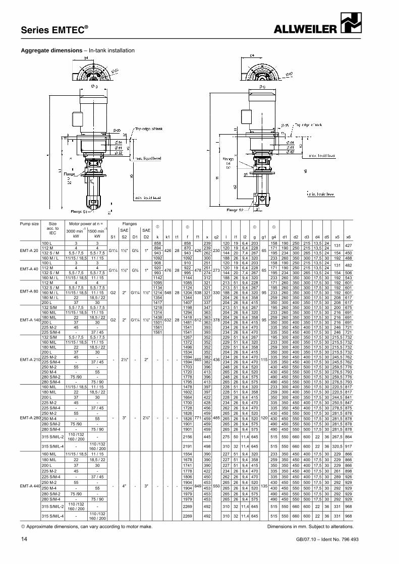
Aggregate dimensions – In-tank installation
Pump size Size acc. to
IEC
Motor power at n = Flanges
k k1 t1
f
g
g4
3000 min-1
kW
1500 min-1
kW
SAE SAE
f1 x q2 l l1 l2 g1 d1 d2 d3 d4 d5 x5 x6 S1 S2 D1 D2
EMT-A 20
100 L 3 3
G1¼ 1½″ G¾ 1″
858
426 28
858
426
239
230
120 19 6,4 203
65
158 190 250 215 13,5 24 131 427
112 M 4 4 894 870 239 120 19 6,4 228 171 190 250 215 13,5 24 132 S / M 5,5 / 7,5 5,5 / 7,5 943 943 262 144 20 7,4 267 195 234 300 265 13,5 24 154 450160 M / L 11/15 / 18,5 11 / 15 1092 1092 300 188 26 9,4 320 233 260 350 300 17,5 30 192 488
EMT-A 40
100 L 3 3
G1¼ 1½″ G¾ 1″
908
476 28
910
478
251
273
120 19 6,4 203
65
158 190 250 215 13,5 24 131 482
112 M 4 4 920 922 251 120 19 6,4 228 171 190 250 215 13,5 24 132 S / M 5,5 / 7,5 5,5 / 7,5 993 995 274 144 20 7,4 267 195 234 300 265 13,5 24 154 506160 M / L 11/15 / 18,5 11 / 15 1142 1144 312 188 26 9,4 320 233 260 350 300 17,5 30 192 543
EMT-A 80
112 M 4 4
G2 2″ G1¼ 1½″
1095
548 28
1085
538
321
330
213 51 9,4 228
95
171 260 350 300 17,5 30 192 601132 S / M 5,5 / 7,5 5,5 / 7,5 1134 1124 321 213 51 9,4 267 195 260 350 300 17,5 30 192 601160 M / L 11/15 / 18,5 11 / 15 1214 1204 321 188 26 9,4 320 233 260 350 300 17,5 30 192 601180 M / L 22 18,5 / 22 1354 1344 337 204 26 9,4 358 259 260 350 300 17,5 30 208 617200 L 37 30 1417 1407 337 204 26 9,4 415 350 300 400 350 17,5 30 208 617
EMT-A 140
132 S/M 5,5 / 7,5 5,5 / 7,5
G2 2″ G1¼ 1½″
1218
632 28
1198
612
347
378
213 51 9,4 267
95
195 260 350 300 17,5 30 200 675160 M/L 11/15 / 18,5 11 / 15 1314 1294 363 204 26 9,4 320 233 260 350 300 17,5 30 216 691180 M/L 22 18,5 / 22 1438 1418 363 204 26 9,4 358 259 260 350 300 17,5 30 216 691200 L 37 30 1501 1481 363 204 26 9,4 415 350 300 400 350 17,5 30 216 691225 M-2 45 - 1561 1541 393 234 26 9,4 470 335 350 450 400 17,5 30 246 721225 S/M-4 - 37 / 45 1561 1541 393 234 26 9,4 470 335 350 450 400 17,5 30 246 721
EMT-A 210
132 S/M 5,5 / 7,5 5,5 / 7,5
- 2½″ - 2″ - - -
1267
665
352
436
229 51 9,4 267
115
195 300 400 350 17,5 30 215,5 732160 M/L 11/15 / 18,5 11 / 15 1372 352 229 51 9,4 320 233 300 400 350 17,5 30 215,5 732180 M/L 22 18,5 / 22 1496 352 229 51 9,4 358 259 300 400 350 17,5 30 215,5 732200 L 37 30 1534 352 204 26 9,4 415 350 300 400 350 17,5 30 215,5 732225 M-2 45 - 1594 382 234 26 9,4 470 335 350 450 400 17,5 30 245,5 762225 S/M-4 - 37 / 45 1594 382 234 26 9,4 470 335 350 450 400 17,5 30 245,5 762250 M-2 55 - 1703 396 248 26 9,4 520 430 450 550 500 17,5 30 259,5 776250 M-4 - 55 1720 413 265 26 9,4 520 430 450 550 500 17,5 30 276,5 793280 S/M-2 75 /90 - 1778 396 248 26 9,4 575 490 450 550 500 17,5 30 259,5 776280 S/M-4 - 75 / 90 1795 413 265 26 9,4 575 490 450 550 500 17,5 30 276,5 793
EMT-A 280
160 M/L 11/15 / 18,5 11 / 15
- 3″ - 2½″ - - -
1478
771
397
485
228 51 9,4 320
120
233 300 400 350 17,5 30 220,5 817180 M/L 22 18,5 / 22 1602 397 228 51 9,4 358 259 300 400 350 17,5 30 220,5 817200 L 37 30 1664 422 228 26 9,4 415 350 300 400 350 17,5 30 244,5 841225 M-2 45 - 1700 428 234 26 9,4 470 335 350 450 400 17,5 30 250,5 847225 S/M-4 - 37 / 45 1728 456 262 26 9,4 470 335 350 450 400 17,5 30 278,5 875250 M-2 55 - 1826 459 265 26 9,4 520 430 450 550 500 17,5 30 281,5 878250 M-4 - 55 1826 459 265 26 9,4 520 430 450 550 500 17,5 30 281,5 878280 S/M-2 75 /90 - 1901 459 265 26 9,4 575 490 450 550 500 17,5 30 281,5 878280 S/M-4 - 75 / 90 1901 459 265 26 9,4 575 490 450 550 500 17,5 30 281,5 878
315 S/M/L-2 110 /132 160 / 200
- 2156 445 275 50 11,4 645 515 550 660 600 22 36 267,5 864
315 S/M/L-4 - 110 /132 160 / 200
2191 498 310 32 11,4 645 515 550 660 600 22 36 320,5 917
EMT-A 440
160 M/L 11/15 / 18,5 11 / 15
- 4″ - 3″ - - -
1554
849
390
550
227 51 9,4 320
135
233 350 450 400 17,5 30 229 866
180 M/L 22 18,5 / 22 1678 390 227 51 9,4 358 259 350 450 400 17,5 30 229 866
200 L 37 30 1741 390 227 51 9,4 415 350 350 450 400 17,5 30 229 866
225 M-2 45 - 1778 422 234 26 9,4 470 335 350 450 400 17,5 30 261 898
225 S/M-4 - 37 / 45 1806 450 262 26 9,4 470 335 350 450 400 17,5 30 289 926
250 M-2 55 - 1904 453 265 26 9,4 520 430 450 550 500 17,5 30 292 929
250 M-4 - 55 1904 453 265 26 9,4 520 430 450 550 500 17,5 30 292 929
280 S/M-2 75 /90 - 1979 453 265 26 9,4 575 490 450 550 500 17,5 30 292 929280 S/M-4 - 75 / 90 1979 453 265 26 9,4 575 490 450 550 500 17,5 30 292 929
315 S/M/L-2 110 /132 160 / 200
- 2269 492 310 32 11,4 645 515 550 660 600 22 36 331 968
315 S/M/L-4 - 110 /132 160 / 200
2269 492 310 32 11,4 645 515 550 660 600 22 36 331 968
Approximate dimensions, can vary according to motor make. Dimensions in mm. Subject to alterations.
Series EMTEC® with ALLSPEED Controller
GB/07.10 – Ident No. 796 493 15
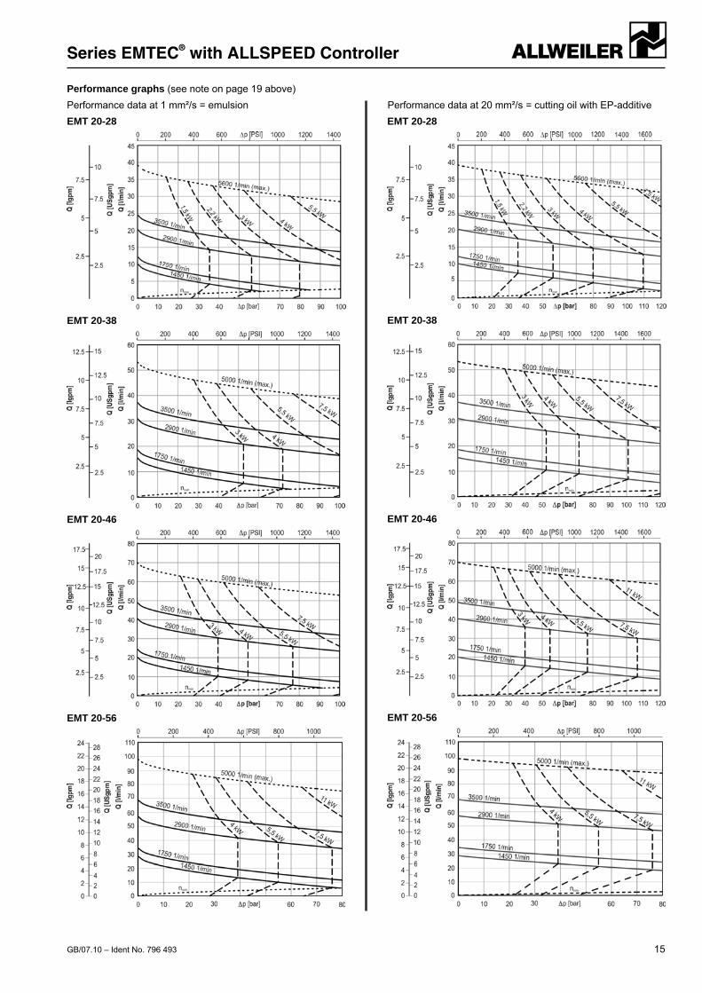
Performance graphs (see note on page 19 above)
Performance data at 1 mm²/s = emulsion Performance data at 20 mm²/s = cutting oil with EP-additive
EMT 20-28
EMT 20-38
EMT 20-46
EMT 20-56
EMT 20-28
EMT 20-38
EMT 20-46
EMT 20-56
Series EMTEC® with ALLSPEED Controller
16 GB/07.10 – Ident No. 796 493
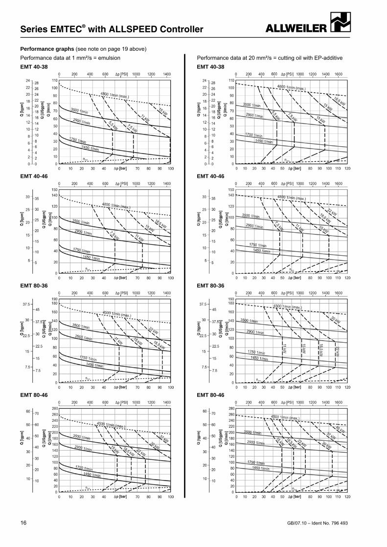
Performance graphs (see note on page 19 above)
Performance data at 1 mm²/s = emulsion Performance data at 20 mm²/s = cutting oil with EP-additive
EMT 40-38
EMT 40-46
EMT 80-36
EMT 80-46
EMT 40-38
EMT 40-46
EMT 80-36
EMT 80-46
Series EMTEC® with ALLSPEED Controller
GB/07.10 – Ident No. 796 493 17
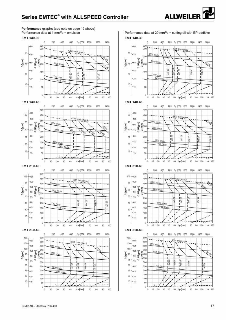
Performance graphs (see note on page 19 above) Performance data at 1 mm²/s = emulsion Performance data at 20 mm²/s = cutting oil with EP-additive
EMT 140-39
EMT 140-46
EMT 210-40
EMT 210-46
EMT 140-39
EMT 140-46
EMT 210-40
EMT 210-46
Series EMTEC® with ALLSPEED Controller
18 GB/07.10 – Ident No. 796 493
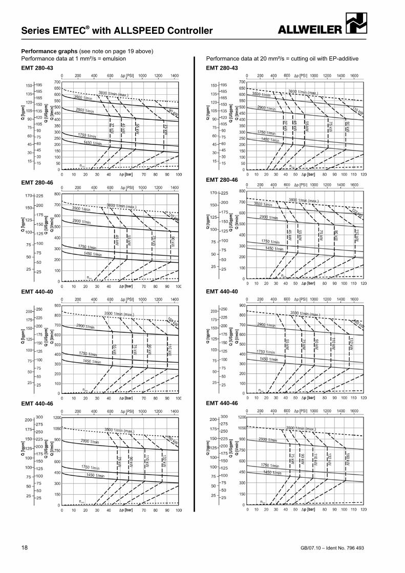
Performance graphs (see note on page 19 above) Performance data at 1 mm²/s = emulsion Performance data at 20 mm²/s = cutting oil with EP-additive
EMT 280-43
EMT 280-46
EMT 440-40
EMT 440-46
EMT 280-43
EMT 280-46
EMT 440-40
EMT 440-46
Series EMTEC®
GB/07.10 – Ident No. 796 493 19
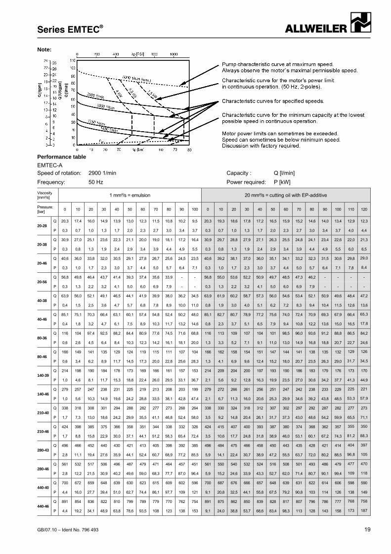
Note:
Performance table
EMTEC-A Speed of rotation: 2900 1/min Capacity : Q [l/min]
Frequency: 50 Hz Power required: P [kW]
Viscosity [mm²/s] 1 mm²/s = emulsion 20 mm²/s = cutting oil with EP-additive
Pressure: [bar]
0 10 20 30 40 50 60 70 80 90 100 0 10 20 30 40 50 60 70 80 90 100 110 120
20-28 Q 20,3 17,4 16,0 14,9 13,9 13,0 12,3 11,5 10,8 10,2 9,5 20,3 19,3 18,6 17,8 17,2 16,5 15,9 15,2 14,6 14,0 13,4 12,9 12,3
P 0,3 0,7 1,0 1,3 1,7 2,0 2,3 2,7 3,0 3,4 3,7 0,3 0,7 1,0 1,3 1,7 2,0 2,3 2,7 3,0 3,4 3,7 4,0 4,4
20-38 Q 30,9 27,0 25,1 23,6 22,3 21,1 20,0 19,0 18,1 17,2 16,4 30,9 29,7 28,8 27,9 27,1 26,3 25,5 24,8 24,1 23,4 22,6 22,0 21,3
P 0,3 0,8 1,3 1,9 2,4 2,9 3,4 3,9 4,4 4,9 5,5 0,3 0,8 1,3 1,9 2,4 2,9 3,4 3,9 4,4 4,9 5,5 6,0 6,5
20-46 Q 40,6 36,0 33,8 32,0 30,5 29,1 27,8 26,7 25,6 24,5 23,5 40,6 39,2 38,1 37,0 36,0 35,1 34,1 33,2 32,3 31,5 30,6 29,8 29,0
P 0,3 1,0 1,7 2,3 3,0 3,7 4,4 5,0 5,7 6,4 7,1 0,3 1,0 1,7 2,3 3,0 3,7 4,4 5,0 5,7 6,4 7,1 7,8 8,4
20-56 Q 56,8 49,8 46,4 43,7 41,4 39,3 37,4 35,6 33,9 - - 56,8 55,0 53,6 52,2 50,9 49,7 48,5 47,3 46,2 - - - -
P 0,3 1,3 2,2 3,2 4,1 5,0 6,0 6,9 7,9 - - 0,3 1,3 2,2 3,2 4,1 5,0 6,0 6,9 7,9 - - - -
40-38 Q 63,9 56,0 52,1 49,1 46,5 44,1 41,9 39,9 38,0 36,2 34,5 63,9 61,9 60,2 58,7 57,3 56,0 54,6 53,4 52,1 50,9 49,6 48,4 47,2
P 0,4 1,5 2,5 3,6 4,7 5,7 6,8 7,8 8,9 10,0 11,0 0,8 1,9 3,0 4,0 5,1 6,2 7,2 8,3 9,4 10,4 11,5 12,6 13,6
40-46 Q 85,1 75,1 70,3 66,4 63,1 60,1 57,4 54,8 52,4 50,2 48,0 85,1 82,7 80,7 78,9 77,2 75,6 74,0 72,4 70,9 69,3 67,9 66,4 65,3
P 0,4 1,8 3,2 4,7 6,1 7,5 8,9 10,3 11,7 13,2 14,6 0,8 2,3 3,7 5,1 6,5 7,9 9,4 10,8 12,2 13,6 15,0 16,5 17,8
80-36 Q 116 104 97,4 92,5 88,2 84,4 80,9 77,6 74,5 71,6 68,8 116 113 109 107 104 101 98,5 96,0 93,6 91,2 88,8 86,5 84,2
P 0,6 2,6 4,5 6,4 8,4 10,3 12,3 14,2 16,1 18,1 20,0 1,3 3,3 5,2 7,1 9,1 11,0 13,0 14,9 16,8 18,8 20,7 22,7 24,6
80-46 Q 166 149 141 135 129 124 119 115 111 107 104 166 162 158 154 151 147 144 141 138 135 132 129 126
P 0,6 3,4 6,2 8,9 11,7 14,5 17,3 20,0 22,8 25,6 28,3 1,3 4,1 6,9 9,6 12,4 15,2 18,0 20,7 23,5 26,3 29,0 31,7 34,5
140-39 Q 214 198 190 184 178 173 169 166 161 157 153 214 209 204 200 197 193 190 186 183 179 176 173 170
P 1,0 4,6 8,1 11,7 15,3 18,8 22,4 26,0 29,5 33,1 36,7 2,1 5,6 9,2 12,8 16,3 19,9 23,5 27,0 30,6 34,2 37,7 41,3 44,9
140-46 Q 279 257 247 238 231 225 219 213 208 203 199 279 272 266 261 256 251 247 242 238 233 229 225 221
P 1,0 5,6 10,3 14,9 19,6 24,2 28,8 33,5 38,1 42,8 47,4 2,1 6,7 11,3 16,0 20,6 25,3 29,9 34,6 39,2 43,8 48,5 53,3 57,9
210-40 Q 338 318 308 301 294 288 282 277 273 268 264 338 330 324 318 312 307 302 297 292 287 282 277 273
P 1,7 7,3 13,0 18,6 24,2 29,9 35,5 41,1 46,8 52,4 58,0 3,5 9,2 14,8 20,4 26,1 31,7 37,3 43,0 48,6 54,2 59,9 65,5 71,1
210-46 Q 424 398 385 375 366 358 351 344 338 332 326 424 415 407 400 393 387 380 374 368 362 357 355 350
P 1,7 8,8 15,8 22,9 30,0 37,1 44,1 51,2 58,3 65,4 72,4 3,5 10,6 17,7 24,8 31,8 38,9 46,0 53,1 60,1 67,2 74,3 81,2 88,3
280-43 Q 496 466 452 440 430 421 413 405 398 392 385 496 484 475 466 458 450 443 435 428 421 414 404 397
P 2,8 11,1 19,4 27,6 35,9 44,1 52,4 60,7 68,9 77,2 85,5 5,9 14,1 22,4 30,7 38,9 47,2 55,5 63,7 72,0 80,2 88,5 96,8 105
280-46 Q 561 532 517 506 496 487 479 471 464 457 451 561 550 540 532 524 516 508 501 493 486 479 477 470
P 2,8 12,2 21,5 30,9 40,2 49,6 59,0 68,3 77,7 87,0 96,4 5,9 15,2 24,6 33,9 43,3 52,7 62,0 71,4 80,7 90,1 99,4 109 118
440-40 Q 700 672 659 648 639 630 623 615 609 602 596 700 687 676 666 657 648 639 631 622 614 606 598 590
P 4,4 16,0 27,7 39,4 51,0 62,7 74,4 86,1 97,7 109 121 9,1 20,8 32,5 44,1 55,8 67,5 79,2 90,8 103 114 126 138 149
440-46 Q 891 854 836 822 810 799 789 779 770 762 754 891 875 862 850 839 828 817 807 796 786 777 768 758
P 4,4 19,2 34,1 48,9 63,8 78,6 93,5 108 123 138 153 9,1 24,0 38,8 53,7 68,6 83,4 98,3 113 128 143 158 173 187
Series EMTEC®
20 GB/07.10 – Ident No. 796 493
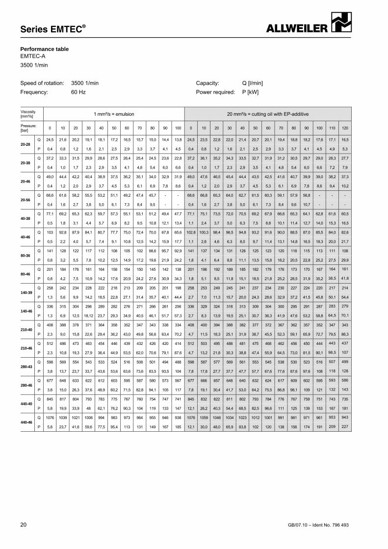
Performance table EMTEC-A
3500 1/min
Speed of rotation: 3500 1/min Capacity: Q [l/min]
Frequency: 60 Hz Power required: P [kW]
Viscosity [mm²/s] 1 mm²/s = emulsion 20 mm²/s = cutting oil with EP-additive
Pressure: [bar]
0 10 20 30 40 50 60 70 80 90 100 0 10 20 30 40 50 60 70 80 90 100 110 120
20-28 Q 24,5 21,6 20,2 19,1 18,1 17,2 16,5 15,7 15,0 14,4 13,8 24,5 23,5 22,8 22,0 21,4 20,7 20,1 19,4 18,8 18,2 17,6 17,1 16,5
P 0,4 0,8 1,2 1,6 2,1 2,5 2,9 3,3 3,7 4,1 4,5 0,4 0,8 1,2 1,6 2,1 2,5 2,9 3,3 3,7 4,1 4,5 4,9 5,3
20-38 Q 37,2 33,3 31,5 29,9 28,6 27,5 26,4 25,4 24,5 23,6 22,8 37,2 36,1 35,2 34,3 33,5 32,7 31,9 31,2 30,5 29,7 29,0 28,3 27,7
P 0,4 1,0 1,7 2,3 2,9 3,5 4,1 4,8 5,4 6,0 6,6 0,4 1,0 1,7 2,3 2,9 3,5 4,1 4,8 5,4 6,0 6,6 7,2 7,9
20-46 Q 49,0 44,4 42,2 40,4 38,9 37,5 36,2 35,1 34,0 32,9 31,9 49,0 47,6 46,5 45,4 44,4 43,5 42,5 41,6 40,7 39,9 39,0 38,2 37,3
P 0,4 1,2 2,0 2,9 3,7 4,5 5,3 6,1 6,9 7,8 8,6 0,4 1,2 2,0 2,9 3,7 4,5 5,3 6,1 6,9 7,8 8,6 9,4 10,2
20-56 Q 68,6 61,6 58,2 55,5 53,2 51,1 49,2 47,4 45,7 - - 68,6 66,8 65,3 64,0 62,7 61,5 60,3 59,1 57,9 56,8 - - -
P 0,4 1,6 2,7 3,8 5,0 6,1 7,3 8,4 9,5 - - 0,4 1,6 2,7 3,8 5,0 6,1 7,3 8,4 9,6 10,7 - - -
40-38 Q 77,1 69,2 65,3 62,3 59,7 57,3 55,1 53,1 51,2 49,4 47,7 77,1 75,1 73,5 72,0 70,5 69,2 67,9 66,6 65,3 64,1 62,8 61,6 60,5
P 0,5 1,8 3,1 4,4 5,7 6,9 8,2 9,5 10,8 12,1 13,4 1,1 2,4 3,7 5,0 6,3 7,5 8,8 10,1 11,4 12,7 14,0 15,3 16,5
40-46 Q 103 92,8 87,9 84,1 80,7 77,7 75,0 72,4 70,0 67,8 65,6 102,8 100,3 98,4 96,5 94,8 93,2 91,6 90,0 88,5 87,0 85,5 84,0 82,6
P 0,5 2,2 4,0 5,7 7,4 9,1 10,8 12,5 14,2 15,9 17,7 1,1 2,8 4,6 6,3 8,0 9,7 11,4 13,1 14,8 16,5 18,3 20,0 21,7
80-36 Q 141 128 122 117 112 108 105 102 98,6 95,7 92,9 141 137 134 131 128 125 123 120 118 115 113 111 108
P 0,8 3,2 5,5 7,8 10,2 12,5 14,9 17,2 19,6 21,9 24,2 1,8 4,1 6,4 8,8 11,1 13,5 15,8 18,2 20,5 22,8 25,2 27,5 29,9
80-46 Q 201 184 176 161 164 158 154 150 145 142 138 201 196 192 189 185 182 179 176 173 170 167 164 161
P 0,8 4,2 7,5 10,9 14,2 17,6 20,9 24,2 27,6 30,9 34,3 1,8 5,1 8,5 11,8 15,1 18,5 21,8 25,2 28,5 31,9 35,2 38,5 41,8
140-39 Q 258 242 234 228 222 218 213 209 205 201 198 258 253 249 245 241 237 234 230 227 224 220 217 214
P 1,3 5,6 9,9 14,2 18,5 22,8 27,1 31,4 35,7 40,1 44,4 2,7 7,0 11,3 15,7 20,0 24,3 28,6 32,9 37,2 41,5 45,8 50,1 54,4
140-46 Q 336 315 304 296 289 282 276 271 266 261 256 336 329 324 318 313 309 304 300 295 291 287 283 279
P 1,3 6,9 12,5 18,12 23,7 29,3 34,9 40,5 46,1 51,7 57,3 2,7 8,3 13,9 19,5 25,1 30,7 36,3 41,9 47,6 53,2 58,8 64,5 70,1
210-40 Q 408 388 378 371 364 358 352 347 343 338 334 408 400 394 388 382 377 372 367 362 357 352 347 343
P 2,3 9,0 15,8 22,6 29,4 36,2 43,0 49,8 56,6 63,4 70,2 4,7 11,5 18,3 25,1 31,9 38,7 45,5 52,3 59,1 65,9 72,7 79,5 86,3
210-46 Q 512 486 473 463 454 446 439 432 426 420 414 512 503 495 488 481 475 468 462 456 450 444 443 437
P 2,3 10,8 19,3 27,9 36,4 44,9 53,5 62,0 70,6 79,1 87,6 4,7 13,2 21,8 30,3 38,8 47,4 55,9 64,5 73,0 81,5 90,1 98,5 107
280-43 Q 598 569 554 543 533 524 516 508 501 494 488 598 587 577 569 561 553 545 538 530 523 516 507 499
P 3,8 13,7 23,7 33,7 43,6 53,6 63,6 73,6 83,5 93,5 104 7,8 17,8 27,7 37,7 47,7 57,7 67,6 77,6 87,6 97,6 108 118 128
280-46 Q 677 648 633 622 612 603 595 587 580 573 567 677 666 657 648 640 632 624 617 609 602 595 593 586
P 3,8 15,0 26,3 37,6 48,9 60,2 71,5 82,8 94,1 105 117 7,8 19,1 30,4 41,7 53,0 64,2 75,5 86,8 98,1 109 121 132 143
440-40 Q 845 817 804 793 783 775 767 760 754 747 741 845 832 822 811 802 793 784 776 767 759 751 743 735
P 5,8 19,9 33,9 48 62,1 76,2 90,3 104 119 133 147 12,1 26,2 40,3 54,4 68,5 82,5 96,6 111 125 139 153 167 181
440-46 Q 1076 1039 1021 1006 994 983 973 964 955 946 938 1076 1059 1046 1034 1023 1012 1001 991 981 971 961 953 943
P 5,8 23,7 41,6 59,6 77,5 95,4 113 131 149 167 185 12,1 30,0 48,0 65,9 83,8 102 120 138 156 174 191 209 227
Baureihe EMTEC®
GB/07.10 – Ident No. 796 493 21
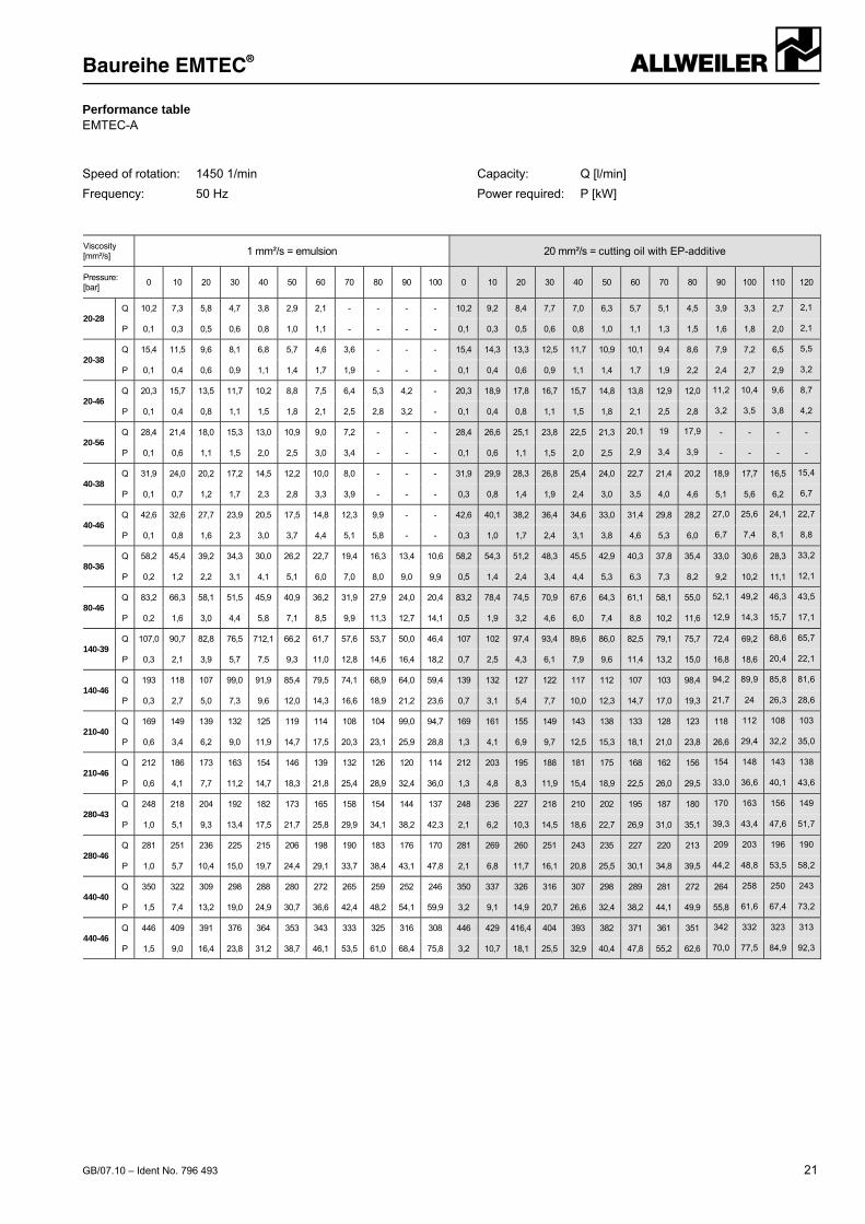
Performance table EMTEC-A
Speed of rotation: 1450 1/min
Frequency: 50 Hz
Capacity: Q [l/min]
Power required: P [kW]
Viscosity [mm²/s] 1 mm²/s = emulsion 20 mm²/s = cutting oil with EP-additive
Pressure: [bar]
0 10 20 30 40 50 60 70 80 90 100 0 10 20 30 40 50 60 70 80 90 100 110 120
20-28 Q 10,2 7,3 5,8 4,7 3,8 2,9 2,1 - - - - 10,2 9,2 8,4 7,7 7,0 6,3 5,7 5,1 4,5 3,9 3,3 2,7 2,1
P 0,1 0,3 0,5 0,6 0,8 1,0 1,1 - - - - 0,1 0,3 0,5 0,6 0,8 1,0 1,1 1,3 1,5 1,6 1,8 2,0 2,1
20-38 Q 15,4 11,5 9,6 8,1 6,8 5,7 4,6 3,6 - - - 15,4 14,3 13,3 12,5 11,7 10,9 10,1 9,4 8,6 7,9 7,2 6,5 5,5
P 0,1 0,4 0,6 0,9 1,1 1,4 1,7 1,9 - - - 0,1 0,4 0,6 0,9 1,1 1,4 1,7 1,9 2,2 2,4 2,7 2,9 3,2
20-46 Q 20,3 15,7 13,5 11,7 10,2 8,8 7,5 6,4 5,3 4,2 - 20,3 18,9 17,8 16,7 15,7 14,8 13,8 12,9 12,0 11,2 10,4 9,6 8,7
P 0,1 0,4 0,8 1,1 1,5 1,8 2,1 2,5 2,8 3,2 - 0,1 0,4 0,8 1,1 1,5 1,8 2,1 2,5 2,8 3,2 3,5 3,8 4,2
20-56 Q 28,4 21,4 18,0 15,3 13,0 10,9 9,0 7,2 - - - 28,4 26,6 25,1 23,8 22,5 21,3 20,1 19 17,9 - - - -
P 0,1 0,6 1,1 1,5 2,0 2,5 3,0 3,4 - - - 0,1 0,6 1,1 1,5 2,0 2,5 2,9 3,4 3,9 - - - -
40-38 Q 31,9 24,0 20,2 17,2 14,5 12,2 10,0 8,0 - - - 31,9 29,9 28,3 26,8 25,4 24,0 22,7 21,4 20,2 18,9 17,7 16,5 15,4
P 0,1 0,7 1,2 1,7 2,3 2,8 3,3 3,9 - - - 0,3 0,8 1,4 1,9 2,4 3,0 3,5 4,0 4,6 5,1 5,6 6,2 6,7
40-46 Q 42,6 32,6 27,7 23,9 20,5 17,5 14,8 12,3 9,9 - - 42,6 40,1 38,2 36,4 34,6 33,0 31,4 29,8 28,2 27,0 25,6 24,1 22,7
P 0,1 0,8 1,6 2,3 3,0 3,7 4,4 5,1 5,8 - - 0,3 1,0 1,7 2,4 3,1 3,8 4,6 5,3 6,0 6,7 7,4 8,1 8,8
80-36 Q 58,2 45,4 39,2 34,3 30,0 26,2 22,7 19,4 16,3 13,4 10,6 58,2 54,3 51,2 48,3 45,5 42,9 40,3 37,8 35,4 33,0 30,6 28,3 33,2
P 0,2 1,2 2,2 3,1 4,1 5,1 6,0 7,0 8,0 9,0 9,9 0,5 1,4 2,4 3,4 4,4 5,3 6,3 7,3 8,2 9,2 10,2 11,1 12,1
80-46 Q 83,2 66,3 58,1 51,5 45,9 40,9 36,2 31,9 27,9 24,0 20,4 83,2 78,4 74,5 70,9 67,6 64,3 61,1 58,1 55,0 52,1 49,2 46,3 43,5
P 0,2 1,6 3,0 4,4 5,8 7,1 8,5 9,9 11,3 12,7 14,1 0,5 1,9 3,2 4,6 6,0 7,4 8,8 10,2 11,6 12,9 14,3 15,7 17,1
140-39 Q 107,0 90,7 82,8 76,5 712,1 66,2 61,7 57,6 53,7 50,0 46,4 107 102 97,4 93,4 89,6 86,0 82,5 79,1 75,7 72,4 69,2 68,6 65,7
P 0,3 2,1 3,9 5,7 7,5 9,3 11,0 12,8 14,6 16,4 18,2 0,7 2,5 4,3 6,1 7,9 9,6 11,4 13,2 15,0 16,8 18,6 20,4 22,1
140-46 Q 193 118 107 99,0 91,9 85,4 79,5 74,1 68,9 64,0 59,4 139 132 127 122 117 112 107 103 98,4 94,2 89,9 85,8 81,6
P 0,3 2,7 5,0 7,3 9,6 12,0 14,3 16,6 18,9 21,2 23,6 0,7 3,1 5,4 7,7 10,0 12,3 14,7 17,0 19,3 21,7 24 26,3 28,6
210-40 Q 169 149 139 132 125 119 114 108 104 99,0 94,7 169 161 155 149 143 138 133 128 123 118 112 108 103
P 0,6 3,4 6,2 9,0 11,9 14,7 17,5 20,3 23,1 25,9 28,8 1,3 4,1 6,9 9,7 12,5 15,3 18,1 21,0 23,8 26,6 29,4 32,2 35,0
210-46 Q 212 186 173 163 154 146 139 132 126 120 114 212 203 195 188 181 175 168 162 156 154 148 143 138
P 0,6 4,1 7,7 11,2 14,7 18,3 21,8 25,4 28,9 32,4 36,0 1,3 4,8 8,3 11,9 15,4 18,9 22,5 26,0 29,5 33,0 36,6 40,1 43,6
280-43 Q 248 218 204 192 182 173 165 158 154 144 137 248 236 227 218 210 202 195 187 180 170 163 156 149
P 1,0 5,1 9,3 13,4 17,5 21,7 25,8 29,9 34,1 38,2 42,3 2,1 6,2 10,3 14,5 18,6 22,7 26,9 31,0 35,1 39,3 43,4 47,6 51,7
280-46 Q 281 251 236 225 215 206 198 190 183 176 170 281 269 260 251 243 235 227 220 213 209 203 196 190
P 1,0 5,7 10,4 15,0 19,7 24,4 29,1 33,7 38,4 43,1 47,8 2,1 6,8 11,7 16,1 20,8 25,5 30,1 34,8 39,5 44,2 48,8 53,5 58,2
440-40 Q 350 322 309 298 288 280 272 265 259 252 246 350 337 326 316 307 298 289 281 272 264 258 250 243
P 1,5 7,4 13,2 19,0 24,9 30,7 36,6 42,4 48,2 54,1 59,9 3,2 9,1 14,9 20,7 26,6 32,4 38,2 44,1 49,9 55,8 61,6 67,4 73,2
440-46 Q 446 409 391 376 364 353 343 333 325 316 308 446 429 416,4 404 393 382 371 361 351 342 332 323 313
P 1,5 9,0 16,4 23,8 31,2 38,7 46,1 53,5 61,0 68,4 75,8 3,2 10,7 18,1 25,5 32,9 40,4 47,8 55,2 62,6 70,0 77,5 84,9 92,3
Series EMTEC®
22 GB/07.10 – Ident No. 796 493
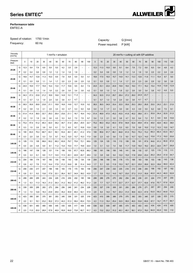
Performance table EMTEC-A
Speed of rotation: 1750 1/min
Frequency: 60 Hz
Capacity: Q [l/min]
Power required: P [kW]
Viscosity [mm²/s] 1 mm²/s = emulsion 20 mm²/s = cutting oil with EP-additive
Pressure: [bar]
0 10 20 30 40 50 60 70 80 90 100 0 10 20 30 40 50 60 70 80 90 100 110 120
20-28 Q 12,3 9,4 7,9 6,8 5,9 5,0 4,2 3,5 2,8 - - 12,3 11,3 10,5 9,8 9,1 8,4 7,8 7,2 6,6 6,0 5,4 4,8 4,2
P 0,2 0,4 0,6 0,8 1,0 1,2 1,4 1,6 1,8 - - 0,2 0,4 0,6 0,8 1,0 1,2 1,4 1,6 1,8 2,0 2,2 2,4 2,6
20-38 Q 18,6 14,7 12,8 11,3 10,0 8,9 7,8 6,8 5,9 5,0 4,1 18,6 17,5 16,5 15,7 14,9 14,1 13,3 12,6 11,8 11,1 10,4 9,7 9,0
P 0,1 0,5 0,8 1,1 1,4 1,7 2,0 2,3 2,6 2,9 3,2 0,1 0,5 0,8 1,1 1,4 1,7 2,0 2,3 2,6 2,9 3,2 3,6 3,9
20-46 Q 24,5 19,9 17,7 15,9 14,4 13,0 11,7 10,6 9,5 8,4 7,4 24,5 23,1 22,0 20,9 19,9 19,0 18,0 17,1 16,2 15,4 14,6 13,8 12,9
P 0,1 0,6 1,0 1,4 1,8 2,2 2,6 3,0 3,4 3,8 4,2 0,1 0,6 1,0 1,4 1,8 2,2 2,6 3,0 3,4 3,8 4,2 4,6 5,0
20-56 Q 34,3 27,3 23,9 21,2 18,9 16,8 14,9 13,1 11,4 - - 34,3 32,5 31,0 29,7 28,4 27,2 26,0 24,9 23,7 - - - -
P 0,1 0,7 1,3 1,9 2,4 3,0 3,6 4,1 4,7 - - 0,1 0,7 1,3 1,9 2,4 3,0 3,6 4,1 4,7 - - - -
40-38 Q 38,5 30,6 26,8 23,8 21,1 18,8 16,6 14,6 12,7 10,9 9,2 38,5 36,5 34,9 33,4 32,0 30,6 29,3 28,0 26,8 25,5 24,3 23,1 21,9
P 0,2 0,8 1,5 2,1 2,8 3,4 4,0 4,7 5,3 6,0 6,6 0,4 1,0 1,7 2,3 3,0 3,6 4,3 4,9 5,5 6,2 6,8 7,5 8,1
40-46 Q 51,4 41,4 36,5 32,7 29,3 26,4 23,6 21,1 18,7 16,4 14,2 51,4 48,9 47,0 45,2 43,5 41,8 40,2 38,6 37,1 35,8 34,4 32,9 31,5
P 0,2 1,0 1,9 2,8 3,6 4,5 5,3 6,2 7,0 7,9 8,7 0,4 1,3 2,1 3,0 3,8 4,7 5,5 6,4 7,2 8,1 8,9 9,8 10,6
80-36 Q 70,2 57,4 51,2 46,3 42,0 38,2 34,7 31,4 28,4 25,5 22,7 70,2 66,3 63,2 60,3 57,6 54,9 52,4 49,9 47,4 45,0 42,6 40,3 38,0
P 0,3 1,5 2,6 3,8 5,0 6,1 7,3 8,5 9,7 10,8 12,0 0,6 1,8 3,0 4,1 5,3 6,5 7,6 8,8 10,0 11,2 12,3 13,5 14,7
80-46 Q 100 83,5 75,3 68,7 63,1 58,1 53,4 49,1 45,1 41,2 37,6 100 95,6 91,7 88,1 84,8 81,5 78,3 75,3 72,2 69,3 66,4 63,5 60,7
P 0,3 2,0 3,6 5,3 7,0 8,7 10,3 12,0 13,7 15,3 17,0 0,6 2,3 4,0 5,6 7,3 9,0 10,7 12,3 14,0 15,6 17,3 19,0 20,6
140-39 Q 129 113 105 98,6 93,2 88,3 83,9 79,7 75,8 72,1 68,6 129 124 120 116 112 108 105 101 97,9 94,6 91,3 90,8 87,8
P 0,5 2,6 4,8 6,9 9,1 11,2 13,4 15,5 17,7 19,8 22,0 1,0 3,1 5,3 7,4 9,6 11,7 13,9 16,0 18,2 20,3 22,5 24,7 26,8
140-46 Q 168 147 136 128 121 114 108 103 97,7 92,8 88,2 168 161 156 150 145 141 136 132 127 123 119 115 111
P 0,5 3,3 6,1 8,9 11,7 14,5 17,3 20,1 22,9 25,7 28,5 1,0 3,8 6,6 9,4 12,2 15,0 17,8 20,6 23,4 26,2 29,0 31,9 34,7
210-40 Q 204 184 174 167 160 154 148 143 139 134 130 204 196 190 184 178 173 168 163 158 153 148 143 138
P 0,8 4,2 7,6 11,0 14,4 17,8 21,2 24,6 28 31,4 34,8 1,7 5,1 8,5 11,9 15,3 18,7 22,1 25,5 28,9 32,3 35,6 39,0 42,4
210-46 Q 256 230 217 207 198 190 183 176 170 164 158 256 247 239 232 225 218 212 206 200 198 192 187 182
P 0,8 5,1 9,3 13,6 17,9 22,1 26,4 30,7 34,9 39,2 43,5 1,7 5,9 10,2 14,5 18,7 23,0 27,3 31,5 35,8 40,0 44,3 48,5 52,8
280-43 Q 299 269 255 243 234 225 216 209 202 195 189 299 288 278 270 262 254 246 239 231 224 214 207 200
P 1,3 6,3 11,3 16,3 21,3 26,3 31,2 36,2 41,2 46,2 51,2 2,8 7,7 12,7 17,7 22,7 27,7 32,7 37,7 42,6 47,6 52,7 57,6 62,6
280-46 Q 339 309 295 283 273 264 256 248 241 234 228 339 327 318 309 301 293 286 278 271 267 261 254 248
P 1,3 7,0 12,6 18,3 23,9 29,5 35,2 40,8 46,5 52,1 57,8 2,8 8,4 14,0 19,7 25,3 31,0 36,6 42,3 47,9 53,5 59,2 64,8 70,5
440-40 Q 423 395 381 370 361 353 345 338 331 325 319 423 410 399 389 379 370 362 353 345 337 328 323 315
P 2,0 9,1 16,1 23,2 30,2 37,3 44,3 51,3 58,4 65,4 72,5 4,3 11,3 18,4 25,4 32,5 39,5 46,5 53,6 60,6 67,7 74,7 81,7 88,7
440-46 Q 538 501 483 469 456 445 435 426 417 408 400 538 522 509 497 485 474 463 453 443 434 424 415 405
P 2,0 11,0 20,0 28,9 37,9 46,9 55,8 64,8 73,8 82,7 91,7 4,3 13,2 22,2 31,2 40,1 49,1 58,1 67,0 76,0 84,9 93,9 103 112
Series EMTEC®
GB/07.10 – Ident No. 796 493 23
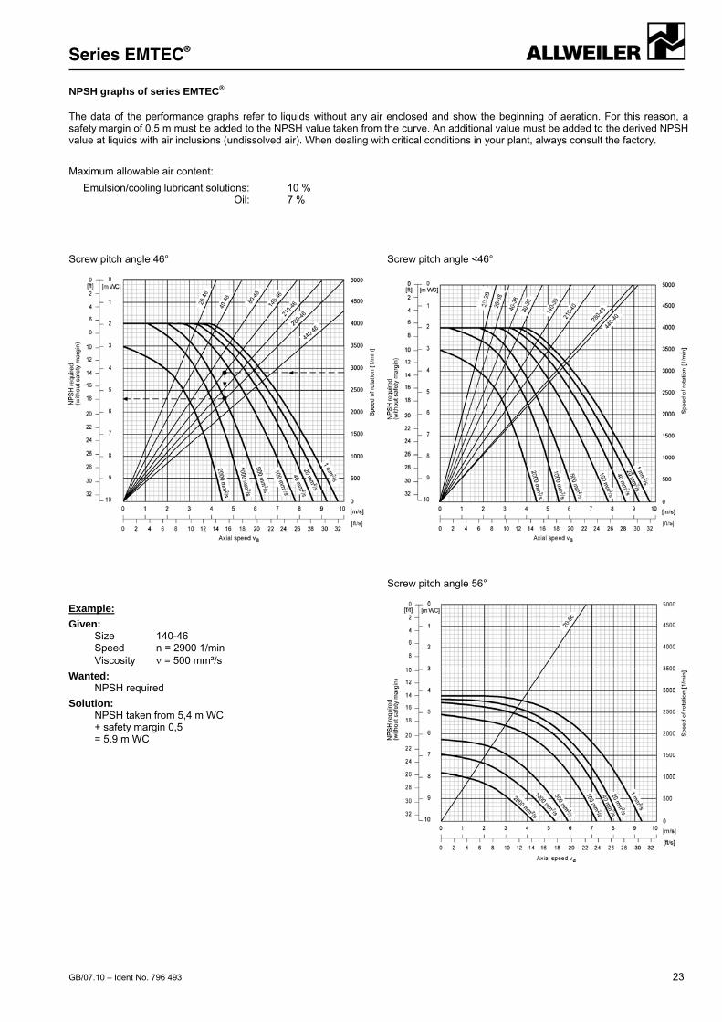
NPSH graphs of series EMTEC® The data of the performance graphs refer to liquids without any air enclosed and show the beginning of aeration. For this reason, a safety margin of 0.5 m must be added to the NPSH value taken from the curve. An additional value must be added to the derived NPSH value at liquids with air inclusions (undissolved air). When dealing with critical conditions in your plant, always consult the factory.
Maximum allowable air content:
Emulsion/cooling lubricant solutions: 10 % Oil: 7 % Screw pitch angle 46° Screw pitch angle <46°
Screw pitch angle 56°
Example:
Given: Size 140-46
Speed n = 2900 1/min Viscosity = 500 mm²/s
Wanted: NPSH required
Solution: NPSH taken from 5,4 m WC + safety margin 0,5 = 5.9 m WC
Series EMTEC®
GB/07.10 – Ident No. 796 493
Subject to technical alterations.
ALLWEILER AG Postfach 1140 78301 Radolfzell Allweilerstr. 1 78315 Radolfzell Germany Tel. +49 (0)7732 86-0 Fax. + 49 (0)7732 86-436 E-mail: [email protected] Internet: http://www.allweiler.com