Embed Size (px)
Citation preview
SCREW COMPRESSORS IN REFRIGERATION AND AIR CONDITIONING
Professor Nikola Stošić
Centre for Positive Displacement Compressor Technology
City University, London, EC1V 0HB, England
ABSTRACT
Recent advances in the techniques of manufacture of vital parts, such as rotors and bearings, have enabled improvements to be made to screw compressors, which were difficult to imagine only a few years ago. This has inevitably influenced the prospects for these machines in refrigeration and air conditioning applications. Some aspects of this are presented, together with well known but not always fully appreciated principles of rational screw compressor design. Despite the improvements already achieved, there is a continuing need to make refrigeration compressors operate more quietly, reliably and with higher efficiencies over a long service life. This can best be done, with the minimum of experimental development, by consideration of all the relevant variables that affect their operation, at the design stage. An evolving means of doing this is to include all these factors simultaneously in multivariable optimisation procedures and examples of these are included. Several innovative ideas, some of them not necessarily new, but only recently considered or put into practice, are reviewed and it is shown how the scope for such machines can be widened by performing more than one function within a single pair of rotors, such as two stage compression or combining compression with expansion.
Keywords: Refrigeration, Screw Compressor, Design, Rotor, Optimisation, Efficiency, Noise, Reliability
NOTATION A Area of passage cross section, oil droplet total surface a Speed of sound C Rotor centre distance, specific heat capacity d Oil droplet Sauter mean diameter x,y,z Rotor Cartesian coordinate directions h Specific enthalpy h=h(θ), convective heat transfer coefficient between oil
and gas k Time constant m Mass m Inlet or exit mass flow rate ( )m m θ= p Rotor lead, Fluid pressure in the working chamber p = p(θ) Q Heat transfer rate between the fluid and the compressor surroundings ( )Q Q θ= r Rotor radius s Distance between the pole and rotor contact points T Torque, Temperature U Internal energy W Work output

V Local volume of the compressor working chamber ( )V V θ=
V Volume flow x Rotor coordinate, Dryness fraction y Rotor coordinate Greek letters ηi Adiabatic efficiency ηt Isothermal efficiency ηv Volumetric efficiency θ Male rotor angle of rotation ζ Compound, local and point resistance coefficient ω Αngular speed of rotation of the male rotor Prefixes d differential ∆ Ιncrement Subscripts f Saturated liquid g Saturated vapour in Fluid inflow ind Indicator l Leakage oil Oil out Fluid outflow p Previous step in iterative calculation w pitch circle 1 male rotor, upstream condition 2 female rotor, downstream condition
INTRODUCTION
Compressors used for industrial, commercial and domestic applications consume approximately 17% of the world’s electrical power output. The majority of these are of the positive displacement type, of which the present world production rate is in excess of 200 million units per year. Most of these are required for compressed air and refrigeration systems. Although reciprocating compressors still dominate this market, many other types have a substantial share of it. Among these, screw compressors have a growing role, especially where the power requirement is high and machine sizes are relatively large.
Apart from their use in refrigeration and air conditioning systems, a significant number of screw compressors are used in the building engineering, food, process and pharmaceutical industries and also for metallurgical and pneumatic transport applications.
Screw compressors are essentially simple volumetric machines, in which the moving parts all operate with pure rotational motion. This enables them to operate at higher speeds with less wear than most other types of compressor. Consequently, they are up to five times lighter than their reciprocating counterparts of the same capacity and have a nearly ten times longer operating life
between overhauls. Furthermore, their internal geometry is such that they have a negligible clearance volume and leakage paths within them decrease in size as compression proceeds. Thus, provided that the running clearances, between the rotors and between the rotors and their housing, are small, they can maintain high volumetric and adiabatic efficiencies over a wide range of operating pressures and flows. Specialised machine tools now enable the most complex rotor shapes to be manufactured with tolerances of the order of 5 µm or less at an affordable cost. The use of these in screw compressor manufacture, together with advances in rolling element bearings, in which the rotors are retained, have led to great improvements in performance and an increasing percentage of all positive displacement compressors sold and currently in operation to be of this type. Consequently, as pointed out by Fleming et al 1998, in a review of contemporary design, modelling and optimisation of screw compressors, mainly for refrigeration, the development of these machines is one of the great success stories of the last quarter of the twentieth century, whereas prior to that time they were hardly used.
Historically, Lysholm, 1942 was the first to publish a work on the asymmetric screw rotor profile, with a small blow-hole area, which formed the basis for modern screw compressor profiles. The invention of oil flooding, in 1955, was a major breakthrough in the application of screw compressor, which resulted in cheaper machines without synchronisation gears and seals and consequently their ever increasing popularity in refrigeration. However, serious work on screw compressors started only about 30 years ago when it first became possible to manufacture rotors which met the requirements for reasonable compressor efficiency. Since then many patents in the field of screw compressor rotor profiles have led to successful contemporary designs. Typically, Bammert, 1979, Shibbie, 1979, Astberg 1982, and Ohman, 2000, patented their work in asymmetric and ‘low’ contact force rotors. Their profiles were used for a large number of applications, starting, mainly with air compressors, but followed, almost immediately, with refrigeration. Rinder, 1987, patented rotors, which have been used exclusively in refrigeration compressors. Kasuya, 1983, Lee, 1988 and Chia-Hsing 1995 patented rotors especially for refrigeration, which later spread out to other fields. The rotors patented by Stosic, 1996 describe a family of rotors, suitable for a wide range of uses, of which refrigeration is a major application.
Despite the increasing popularity of screw compressors, public awareness and understanding of their mode of operation still limited. The earliest reference textbooks by Sakun, 1960 and Amosov et al, 1977, were published in Russian. Subsequently, Rinder, 1979, and Konka, 1988, published books in German, while works in English came only later by O’Neill, 1993 and Arbon, 1994. Recently, Xing, 2000 published a reference textbook in Chinese, which has already made a positive impact on the new screw compressor manufacturers in the Far East. Textbooks on gears give a very useful background to the understanding of the principles of screw rotor profiling. One of these, by Litvin, 1994, has recently been used as a serious reference for screw compressor rotor profiling. Only lately, have more journal publications appeared on screw compressors, such as that of Fujiwara et al, 1995, who described their seminal work on screw compressor modelling, which has been much used for the development of a variety of types of compressor, including those for refrigeration systems.
Currently, there are regular international conferences held on compressors. These are, Purdue University compressor engineering conference in the USA, the IMechE conference on compressors and their systems, in the UK, the SRM Technical Conference in Sweden, the VDI ‘Schraubenkompressoren Tagung’ in Germany, and the Compressor Technique conference in China. Despite being limited only to SRM licensees, the Sweden conference is well attended and

makes regular contributions to the state of the art of screw compressors and it is, as well as the German conference exclusively devoted to screw machines. All these conferences are valuable sources for up to date information on screw compressors. For example, Sangfors, 1982, presented one of the first papers on the contemporary modelling of screw compressor processes. Sauls wrote a series of papers, between 1992 and 2002 which outlined important routes and suggested actions needed to produce better refrigeration screw compressors.
It is impossible to review progress on screw compressors without taking account of the work devoted to rotor manufacturing, tooling and machine tool development. A significant advance in this area has been the combining of simultaneous grinding with profile inspection and its correction, a contemporary practice, which is becoming increasingly popular, Holmes and Stephen 1999. Competition between the machine tool manufacturers for screw rotor production is today as fierce as among the compressor manufacturers.
In recent years there have been a number of lively mergers and buy ups of small compressor companies by larger ones. Moreover, new markets in China, India and other developing countries have led to new screw compressor companies being formed, as well as factories being built there by the major manufacturers. The new companies redirect a great proportion of their profits into screw compressor development and are rapidly acquiring knowledge of compressor technology. A number of traditional compressor companies, facing fresh competition, have responded swiftly to this challenge and are following their example. This has resulted in the demand for institutions, specialising in screw compressor research and development, which can provide services to the screw compressor industry, especially for new manufacturers, who do not have their own design and test facilities
Research in and development of rotor profiles have recently been both stimulated and facilitated by advances in mathematical modelling and computer simulation of the heat and fluid flow processes within the compressor. These analytical methods may be combined to form powerful tools for process analysis and optimisation and are steadily gaining in credibility as a means of improving design procedures. The earlier approach of intuitive changes, verified by tedious trial and error testing, is thereby slowly, but inevitably being eliminated. As a result, the optimum design of screw compressors has substantially evolved over the past ten years and is likely to lead to additional improvements in machine performance in the near future.
Now that tight clearances are achievable, internal compressor leakage rates have become small. Hence, further improvements are only possible by the introduction of more refined design principles. A key requirement for the successful design of all types of compressor is the ability to predict accurately the effects on performance of the change in any design parameter such as clearance, rotor profile shape, oil or fluid injection position and rate, rotor diameter and proportions and speed. In the case of screw compressors, the main requirement is to improve the rotor profiles so that the internal flow area through the compressor is maximised while the leakage path is minimised. Also, internal friction due to relative motion between the contacting rotor surfaces should be made as small as possible in order to permit higher rotor speeds without excessive mechanical losses. Recent improvements in bearing design make process fluid lubrication possible in some applications. Also seals are more efficient today. All these developments can be utilised to produce more efficient, lighter and cheaper screw compressors.

The development of screw compressors for refrigeration systems is now so advanced, that no detail in the design of their rotors, casings and other components may be neglected if manufacturers are to remain competitive. Despite this, there is still scope for significant improvement both through better rotor profiling and the application of optimisation methods to the entire compressor design. The full compressor optimisation, which hitherto have not been extensively used, are especially important and, when properly applied, leads to a unique compressor design for each application.
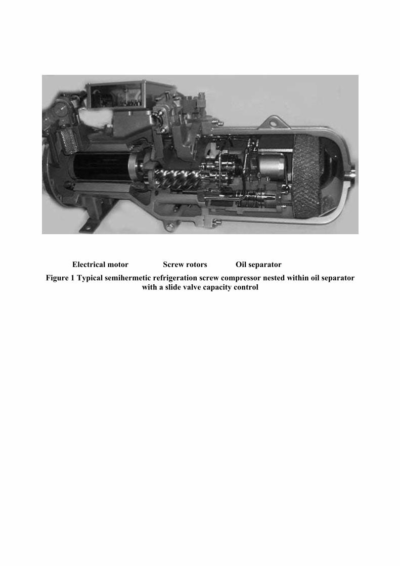
Figure 1 Typical semihermetic refrigeration screw compressor nested within oil separator with a slide valve capacity control
A typical semihermetic compressor for refrigeration and air conditioning applications is presented in Fig. 1. This comprises the electrical motor on the left and the screw compressor block with its flow control system and oil separator on the right.
Screw compressors in normal use today are built around rotors whose outer diameters range between about 75 and 620 mm. These deliver between 0.6 m3/min and 120 m3/min of compressed gas for oil-flooded applications and between 5 and 600 m3/min in the dry mode. The normal pressure ratios attained in a single stage are 3.5:1 for dry compressors and up to 15:1 for oil flooded machines. Usual stage pressure differences are up to 15 bars, but maximum values sometimes exceed 40 bars. Typically, the volumetric efficiency of these machines now is over 90% while specific power inputs, which are both size and performance dependent, have been reduced to values which were regarded as unattainable only a few years ago.
In the field of refrigeration, the use of reciprocating and vane compressors is decreasing while the number of screw machines is expected to increase in the coming years. Large scroll compressors are starting to infiltrate into the already established range of screw compressors, while small screw compressors compete with the upper range of scroll compressors. Since refrigeration and process gas screw compressors operate for long periods, they must be designed to have a high efficiency. In this respect the screw has some advantages over the scroll in areas where either can be used. The main advantage of screw compressors over flow compressors is their fairly large pressure ratio and their excellent part load characteristic.
BASIC PRINCIPLES AND CONCEPTS OF SCREW COMPRESSOR OPERATION
Although screw compressors have been in service for many years, their working principles and basic concepts still require some explanation.
Figure 2 Screw compressor main components, rotors and housings with bearings
Screw compressors are positive displacement rotary machines which consist essentially of a pair of meshing helical lobed rotors, contained in a casing. Together, these form a series of working chambers. As shown in Fig 2, the male right and female left rotor are both surrounded by a casing, containing the suction and discharge ports, which are exposed to external pressure. Admission of the gas to be compressed occurs through the suction port. This is formed by opening the casing surrounding the top face of the rotors. Exposure of the space between the rotor lobes to the suction port, as their front ends pass across it, allows the gas to fill the passages

formed between them and the casing. Further rotation then leads to cut off of the port and progressive reduction in the trapped volume in each passage until the front ends of the passages between the rotors are exposed to the high pressure discharge port. The gas then flows out through this at approximately constant pressure.
Rotor Geometry
Screw compressor geometry is based on relatively simple basic concepts which have often been misunderstood or misinterpreted and thereby not often properly used in everyday practice. The fundamental concepts on which it is based are presented here, but a more complete analysis is given in Stosic 1998, and that may be used as a good starting point for those who wish to derive their own shapes with more complex lobe proportions.
A pair of screw compressor rotors with parallel axes and a uniform lead is presented in Fig. 3, with the male rotor on the left and the female on the right. The centre line distance between them is C = r1w+r2w, where r1w and r2w are the rotor pitch circle radii. The rotors make line contact with each other and the meshing criterion in the transverse plane perpendicular to their axes is the same as that of helical gears.
The profile point coordinates in the transverse plane through x01 and y01 of one rotor and their
first derivative 01
01
dydx
must be known. This profile may be specified on either the male or female
rotors or in sequence on both. The profile may also be defined as a rack, which is a rotor of infinite radius and an infinite number of lobes.
Figure 3 Rotor coordinate systems
The meshing condition for a screw machine rotor derived from the envelope condition is that a primary curve generates or envelopes a secondary one when they both rotate around their axes. Then the rotor meshing condition, as presented in Eq. 1, is:
0101 01
01
sin cos 0dy C Cky kxdx i i
θ⎛ ⎞− + +⎜ ⎟⎝ ⎠
θ = (1)
where i = p2/p1 and k = 1-1/i and p is the rotor unit lead, which is the rotor lead divided by 2π. θ is the angle of rotation of the male rotor at which the point of contact is made between the male and female rotors and this equation can be solved with respect to it, only numerically. Once the distribution of θ along the profile is obtained, it may be used both to calculate the meshing rotor profile point coordinates and the helicoid surfaces, formed in space by the screw compressor rotors, and to determine the sealing lines and paths of proximity between the two rotors. Rotor rack coordinates may also be calculated from the same θ distribution.
The meshing profile coordinates of the female rotor in the transverse plane are then calculated in Eq. 2:

02 01 01
02 01 01
cos sin cos
sin cos sin
x x k y k Ci
y x k y k Ci
θθ θ
θθ θ
= − −
= + + (2)
When the rack-to-rotor gear ratio i tends to infinity, the coordinates, so obtained, correspond to those of the rack. Thus:
0 01 01
0 01 01 1
cos sinsin cos
r
r w
x x yy x y r
θ θθ θ
= −= + − θ
(3)
Conversely, if the female rotor curves are given, similar equations with substituted indices can be used to generate the male rotor profile.
If the primary curves are given in rack form, the rack coordinates x0r and y0r, as well as their first
derivative 0
0
r
rdxdy
must be known. Then the generated curves can be calculated at the rotors as:
( )( )
01 0 0 1
01 0 0 1
cos sin
sin cosr r w
r r w
x x y r
y x y r
θ θ
θ θ
= − −
= + − (4)
The meshing condition is then obtained from the relation:
( ) ( )01 0 1 0
0
0rw r w r
r
dyr y r x
dxθ − − − = (5)
θ can then be solved directly, without the need for a numerical procedure to evaluate it. This is the advantage of the generation procedure of the rack over that of the rotor.
The sealing line of screw compressor rotors is somewhat similar to the contact line between gears. Since in fact, there is a clearance gap between rotors, the sealing line is defined as the path of the points of most proximate rotor position. Its coordinates x1, y1and z1 are calculated from the same θ distribution as:
[ ] [ ]1 1 1 01 01 01 01 1, , cos sin , sin cos ,x y z x y x y pθ θ θ θ= − + θ (6)
The aim of the designer is to select rotor profiles which maximise the flow area between the lobes while minimising the blowhole area, the sealing line length and the contact forces between the male and female rotors. Since the male rotor profile lobe perimeter is far longer than that of the female rotor and any increase in the thickness of one must be accompanied by a corresponding decrease in the other, it follows that increasing the thickness of the female rotor lobe will be accompanied by an even bigger decrease of metal on the male rotor. This will result in a larger rotor passage cross sectional area and hence a greater compressor displacement. It therefore

follows that the application of these criteria simultaneously leads to a female rotor profile with stronger lobes.
All these features are presented in Fig. 4, with the male rotor on the left and the female rotor on the right. The y-z component of the sealing line is presented on the left, while the x-y component is located in the figure centre. A unique feature of screw compressor rotors is that the sealing line lengths of the trapped volumes shrink to zero as compression proceeds. This implies that the leakage paths are small or disappear in screw compressor domains subjected to high pressures, which is not the case in piston, or vane compressors and only partially so in scroll compressors. The clearance distribution is represented in Fig. 4 by the distance between the two rotor racks scaled up by a factor of 50 to produce a unique visualisation of the clearance distribution. As can be seen, the rotors can make contact only at the round lobe face very close to the pitch circle.
Figure 4 Screw compressor rotors 1-male, 2-female, 3-rotor external and 4-pitch circles, 5-sealing line, 6-clearance distribution and 7-rotor flow area between the rotors and housing
The rotor sliding velocity is the relative velocity between the two rotor profiles at their contact point. Since the normal velocity component is a common velocity of the two profile points, the sliding component is at the same time the tangential velocity component. The most convenient means of its calculation is to fix the pole point, which is the common point of the two rotor pitch circles and lays between the two rotor centres, and allow the rotors to rotate around the pole by their angular velocities ω1 and ω2. In such a case, the relative velocity between the two rotors is the difference between their absolute velocities, which is given as:
( )
( )1 2
2 201 1 01
s
w
w s
s x r y
ω ω= −
= − + (7)
where s is the distance between the pole and contact point.
It is obvious that the sliding velocity is proportional to the distance s which is small close to the rotor pitch circles and collapses to zero at the pole. Therefore, to obtain rotor contact with a low sliding velocity, the contact should be as close as possible to the rotor pitch circles. In such a case, the rotor contact will be predominantly of the rolling character keeping friction between the rotors low. If the contact occurs away from the pitch circle, the sliding velocity grows and it might cause high friction which is accompanied by the heat dissipation, rotor growth and, finally, rotor seizure.
On the other hand, the sliding velocity should not be zero, but kept to a low value in order to enable the hydrodynamic activity needed for proper lubrication of the oil flooded rotors.
Rotor and Compressor Clearances
In order to operate effectively, a continuous line of contact must be formed between the two rotors and between the rotors and the casing. The length of the contact line between the rotors varies according to the angle of rotation and is maintained throughout the working chamber formed between the two lobes and the casing.
The most convenient procedure used to obtain the rotor interlobe clearance gap is to consider the

gap as the shortest distance between the racks of the male and female rotor sealing points in the cross section normal to the rotor helicoids.
If the rotor racks are obtained from the rotors by the reverse procedure, they will then include all manufacturing and positioning imperfections. Therefore, the resulting clearance distribution effectively represents real compressor clearances. The transverse clearance gap may then be obtained from the normal clearances.
A feature of screw compressors is the small gap which occurs between the cusp of the casing and the rotors at the upper, ‘flat’ lobe face and extends along the length of the casing to form a three dimensional ‘blow-hole’. Gas, being compressed or expanded within the machine, leaks through it. On the ‘round’ lobe face, the blow-hole is considerably larger. However, this can be tolerated, because the pressure difference through that blowhole is extremely low.
Calculation of screw compressor performance Since the compression process in screw machines is subjected to high leakages, oil injection and internal heat transfer, the best approach to the analysis of these machines is first to establish relations which define the instantaneous operating volume within them and how it changes with rotational angle or time. The differential equations of conservation of mass and energy flow through the instantaneous volume, together with a number of algebraic equations defining phenomena associated with the flow may then be applied to each process that the fluid is subjected to within the machine; namely, suction, compression and discharge. If the energy equation is written in its non-steady form, the output parameter derived from its solution is internal energy rather than enthalpy. This is a more convenient term for computation, especially when evaluating the flow of real fluids because their temperature and pressure relationships are not explicit. However, since the internal energy can be expressed as a function of temperature and specific volume only, pressure can subsequently be derived directly from them. All the remaining thermodynamic and fluid properties within the machine cycle are derived from the internal energy and the volume and numerical computation of the processes involved is carried out through several cycles until the solution converges. The working fluid can be any gas or liquid-gas-mixture, i.e. any ideal or real gas or liquid-gas mixture of known properties, but the thermodynamic equations of state and change of state of the fluid and their constituent relationships must be included. Heat transfer between the gas and the compressor and the leakage through the clearances at any stage of the process, as well as oil injection and solubility of the gas in the injected fluid can then be accounted for. The conservation of internal energy presented here for a control volume is:
in in out outdU dVm h m h Q pd
ωd
ωθ θ
⎛ ⎞ = − + −⎜ ⎟⎝ ⎠
(8)
The local rate of change of internal energy with respect to the compressor shaft angle θ is given on the left hand side of Eq 8, while on the right hand side, the inflow and outflow rate of enthalpy and heat and work exchanged through the control volume boundaries are given. The inflow and outflow enthalpies are presented in Eqs. 9 and 10. These comprise the suction and discharge enthalpy flow, as well as the oil injection enthalpy flow and leakage inflow and outflow.

, ,in in suc suc l g l g oil oilm h m h m h m h= + + (9)
, ,out out dis dis l l l lm h m h m h= + (10) The mass continuity equation is:
in outdm m md
ωθ
= − (11)
On the left hand side of Eq. 11 the local rate of change of mass is given, while the mass inflow and outflow are given on the right hand side. The mass inflow and outflow comprise the suction and discharge mass flow, as well as leakage and oil injection mass flows. The instantaneous density ρ = ρ(θ) is obtained from the instantaneous mass m, trapped in the control volume, and the size of the corresponding instantaneous volume V as ρ = m/V. The suction and discharge port flows are defined by the velocity through them and their cross sectional area from: suc suc suc suc dis dis dis dism w A and m w Aρ ρ= = . The cross-section area A is obtained from the compressor geometry, which was considered as a periodic function of the angle of rotation θ. Leakage in a screw machine forms a substantial part of the total flow rate and plays an important role because it affects the delivered mass flow rate and the compressor work and hence both the compressor volumetric and adiabatic efficiencies. A widely accepted model of the leakage flow obtained from the leakage momentum equation is presented by Eq. 12:
2 22 1
2 2
1
2 lnl l l l l
p pm w A Apap
ρζ
−= =
⎛+⎜ ⎟
⎝ ⎠
⎞ (12)
The value ζ is derived from a combination of the local and line resistance coefficients, which are modelled as functions of the Reynolds number of the leakage flow within the gaps. Therefore, the value of ζ contains elements, which account for both the nature of the fluid and the flow conditions in the gaps. These differ for each machine geometry and working condition. The injection of oil or other liquids for lubrication, cooling or sealing purposes, substantially modifies the thermodynamic process in a screw compressor. Special effects, such as gas or its condensate mixing and dissolving in or flashing out of the injected fluid must be accounted for separately if they are expected to affect the process. In addition to lubrication, the major purpose for injecting oil into a compressor is to seal the gaps and cool the gas. The flow of injected oil, the oil inlet temperature and its injection position are additional variables if oil-flooded compressors are being considered. Heat transfer between the oil and the gas may be modelled as a first order dynamic system. If dθ in Eq. 13 is replaced by the small difference ∆θ, the oil temperature can be estimated in the finite difference form from Eq. 14, where the time constant k is given in Eq 15.

( )oil oil oiloil
oil oil
h A T TdTd m cθ ω
−= (13)
,
1oil p
oil
T kTT
k−
=+
(14)
6oil oil oil oil
oil
m c d ckhA hω ω
θ θ= =
∆ ∆ (15)
The convective heat transfer coefficient between the gas and the rotors, h, is calculated by use of Anand’s expression, which is widely used for heat transfer in volumetric machines, Nu=0.023Re0.8. The Sauter mean droplet diameter doil is estimated from the nozzle spray equations. The solution of the equation set in the form of internal energy U and mass m must be performed numerically with appropriate initial and boundary conditions. The initial conditions are selected arbitrarily and the solution is considered to have converged when the difference between two consecutive compressor cycles becomes sufficiently small. Once solved, the values obtained for the internal energy U(θ) and mass in the compressor working chamber m(θ) enable the fluid pressure and temperature to be calculated. Since the volume V(θ) is known, the specific volume is calculated as v = V/m. Therefore, the specific internal energy, u = U/m = f1(T,v) and pressure p = f2(T,v), which are known functions for refrigerant fluids, can be solved to obtain the fluid temperature, T, and pressure, p. This task is simplified because internal energy u can be expressed as a function of temperature and specific volume only. Therefore, f1 and f2 can be solved in sequence. In the case of a wet vapour the fluid phase changes either through evaporation or condensation and the saturation temperature or pressure and vapour quality x have to be solved simultaneously from the internal energy functions: u=xuf+(1-x)ug and v=xvf+(1-x)vg. The solution of the thermodynamic variables, mass and volume provides a basis for more exact computation of all the desired integral characteristics to a satisfactory degree of accuracy. Mass flow rate [kg/s] is given in Eq. 16 where it is calculated from the mass m obtained after integration of the mass Eq. 11, from which the volume flow is calculated by use of Eq. 17 with the suction density ρ
m
suc.
1 / 60m mz n= (16)
/ sucV m ρ= (17) Volumetric efficiency, as presented in Eq. 18 is calculated as the ratio between the mass flow and theoretical mass flow which is given in Eq 19.
vs
mm
η = (18)
( )1 2 1
60s
F F Lnzm
ρ+= (19)
z1 and n are the number of lobes in the male rotor and the male rotor rotational speed respectively. F1 and F2 and L are the male and female rotor cross section and length.

The indicator work Wind [kJ], the indicator power Pind [kW], the specific indicator power Ps [kJ/kg], the adiabatic efficiency ηi and the isothermal efficiency ηt are given in Eqns. 20-23 respectively.
indcycle
W V= dp∫ (20)
1
60ind
indW z nP = (21)
sindPPV
= (22)
t a
t iind ind
W WW
η η= =W (23)
A full and detailed description of the calculation procedure for estimation of the screw compressor performance is given by Hanjalic and Stosic, 1997.
Rotor Pressure Loads
Screw compressor rotors are subjected to severe pressure loads. The rotors, as well as the rotor bearings must therefore satisfy both rigidity and elasticity requirements to ensure their correct and reliable operation.
Figure 5 Pressure forces acting upon screw compressor rotors
The pressure, p(θ) must be known at any instantaneous angle of rotation θ, either by calculation or measurement. This acts in the corresponding interlobes normal to line AB, shown in Fig. 5, which presents the radial and torque forces in the rotor cross section resulting from it. A and B are either on the sealing line between rotors or on the rotor tips. Since they belong to the sealing line, they are fully defined from the rotor geometry.
In position 1, there is no contact point between the rotors. Since A and B are on the circle, overall forces F1 and F2 act towards the rotor axes and are only radial. There is no torque caused by pressure forces in this position. In position 2, there is only one contact point between the rotors, at A. Since the forces F1 and F2 are eccentric, they have both radial and circumferential components, the latter of which cause the torque. Due to the force position, the torque on the female rotor is significantly smaller than on the male rotor. In position 3 there are two contact points on the rotors and the overall and radial forces are equal for both rotors. As in position 2, they also cause torque, which is smaller on the female rotor.
Taking the x direction as parallel to the line between rotor axes O1 and O2 and y as perpendicular to x., the radial force components can be expressed as in Eq. 24:

( )
( )
B
x B AAB
y BA
A
R p dy p y y
R p dx p x x
= − = − −
= − = − −
∫
∫ (24)
while the torque is:
( 2 2 2 20.5B B
B A B AA A
T p xdx p ydy p x x y y= + = − + −∫ ∫ ) (25)
The above equations are integrated along the profile for all profile points. Then they are integrated for all angle steps to complete one revolution employing a given pressure history p=p(θ). Finally, the effects in all the rotor interlobes are added together to produce a record of the rotor forces, taking account of the phase shift, as well as the axial shift between the interlobes.
Since part of the male rotor is always covered by the female rotor in the radial direction, radial forces on the female rotor are usually larger than the corresponding forces on the male rotor, despite the fact that the female rotor may be smaller then the male.
The axial force is the product of the pressure and the interlobe cross sectional area. In one region the interlobes overlap each other. The female rotor covers a small part of the male rotor interlobe, while the male rotor covers the majority of the female interlobe. This causes the axial force on the male rotor to be substantially larger than that on the female one. A correction is allowed for in estimating the axial forces to take account of the fact that the pressure in the rotor end gaps also acts in the axial direction. This is done by assuming the average of the pressures in the two neighbouring interlobes to act on the lobe in question.
Rotor axial forces create moments which act to reduce the radial bearing load at the discharge end and to increase the radial bearing load at the suction end. This is generally an advantage because the suction bearing forces are usually smaller than those on the discharge bearings. Since the male rotor axial force is larger than that of the female, this effect brings more benefit to the male rotor.
Axial bearing reactions are the same as the rotor axial forces. The radial bearing reactions may be calculated from the radial loads by taking moments as in a simple beam loading procedure. It follows that the discharge end bearing forces are far higher than those at the suction end.
Axial loads tend to separate the rotors from the housing at the discharge rotor end, where the end face rotor to housing clearance becomes very important. Similarly, radial forces tend to move the rotors apart, thus increasing the interlobe clearance to its maximum. Therefore, the position of the discharge bearings is a very important factor in rotor clearance management.
The male rotor torque is relatively large and is not so profoundly affected by the rotor profile. However, the female rotor torque, which is obtained as the small value difference between the forces acting on both sides of each lobe, is highly dependent on the rotor profile geometry. Thus changes in the rotor geometry can reverse the sign of the female rotor torque. Therefore, the rotor

profile is the main factor influencing both the sign and magnitude of the female rotor torque. This is particularly important because the torque intensity determines the rotor contact force and consequently friction losses in oil flooded compressors and the sign determines the rotor relative position. Change in sign of the female torque is a cause for the female rotor to lose contact, accelerate and possibly hit the male rotor on either flank in what is known as rotor rattle.
One means of minimising the possibility of rotor rattle is to maintain a relatively large female rotor torque and thereby avoid its reversal during the compression cycle. Rotor contact is therefore made only on one pair of surfaces. Unfortunately, inducing a high positive female torque inevitably results in weaker female rotor lobes and reduced rotor displacement. Consequently, the rotor design for high positive torque on the female rotor results in low flow and relatively high contact forces. These cause lower volumetric and adiabatic efficiencies and reduce mechanical efficiency. An alternative approach is to aim for the so called negative torque, which keeps rotors in permanent contact, but on their flat side.
Significance of the Built-in Volume Ratio in Refrigeration Compressors
Since screw compressors are volumetric machines with a fixed built-in volume ratio, a mismatch of the built-in volume ratio and that required for the actual compressor pressure ratio results in either overcompression or undercompression, as presented in Fig. 6, which causes indicator losses. Only when the built-in volume is adjusted to its pressure ratio requirement does the compressor give its best performance. This value of the built-in volume ratio is the same or very close to the optimum.
Fig. 6 Mismatch in the built-in volume ratio: too large, overcompression, too small, undercompression
The penalty of a built-in volume mismatch is more significant for compressors with small built-in volume ratios than for compressors with large built-in volume ratios. This is because a high built-in volume ratio is associated with a steep slope of the pressure-volume curve. Hence the mismatch area in the p-V diagram, and consequently the loss associated with it is smaller. Moreover, for a large pressure ratio the corresponding indicator work loss due to the built-in volume ratio mismatch is not so big in comparison with the compression work and thereby the penalty is smaller. Surprisingly, this fact is not well appreciated in the compressor industry and the complicated and expensive so called ‘variable’ built-in volume ratio devices which are used to avoid mismatch are not always justified.
DESIGN REQUIREMENTS FOR REFRIGERATION SCREW COMPRESSORS
Refrigeration compressors are required to operate for long periods within closed or inhabited spaces. It is therefore most important that they are quiet, efficient, reliable and durable.
Clearance Management
To perform without causing excessive noise, a compressor must run slowly. Moreover, since speed variation is gradually becoming the main method of controlling the capacity of refrigeration compressors, this requires good efficiency at low speeds. Therefore, leakage paths

should be kept as small as possible in the screw compressors. This implies that a refrigeration screw compressor must be built with small rotor and housing clearances to maintain low leakage and consequent high efficiency under these conditions. The manufacture of rotors by grinding, especially with simultaneous measurement, control and correction of the profile, makes it possible today to maintain a profile tolerance of 5 µm which, in turn, enables the clearances between the rotors to be kept below 15 µm. With such small clearances, rotor contact is very likely and hence the profile and its clearance distribution must be generated in such a manner that damage or seizure will be avoided should this occur.
To avoid this contingency, the clearance distribution should be non-uniform so that hard rotor contact is avoided in rotor areas where sliding motion between the rotors is dominant.
Fig 7 shows how a reduced clearance of 80% is applied in rotor regions close to the rotor pitch circles, while in other regions it is kept to its full size, as was recommended by Edstroem, 1992. As can be seen in Fig 8, the situation regarding rotor contact is now quite different. This is maintained along the rotor contact belt close to the rotor pitch circles but fully avoided at other locations. It follows that if contact should occur, it would be of a rolling character rather than a combination of rolling and sliding or even pure sliding. Such contact will not generate excessive heat and could therefore be maintained for a longer period without damaging the rotors until either the compressor is stopped or contact ceases. A full account of this technique is presented in Stosic et al 2003c.
With such small clearances, thermal dilatations become very important, despite the fact that temperature differences in refrigeration screw compressors are relatively small. Therefore the clearance distribution should be calculated with full allowance for the effects of thermal distortion. One such case is presented in Fig 8 a, which represents the clearance distribution on the cold rotors. After the rotor achieve working temperature conditions, their clearance is presented in Fig 8 b or c.
Figure 7 Variable clearance distribution applied to rotors
According to the female rotor torque sign, rotor contact may be obtained either on the round or flat lobe flank in Figs 8 b and c respectively. Round flank contact is traditional and is usually obtained by maintaining a high, so called positive, female rotor torque. Flat face contact is obtained by maintaining, so called, negative female rotor torque. It offers advantages which have not yet been widely appreciated. Namely, since the sealing line is longer on the flat face than at the round one, as may be seen in Fig. 4, a smaller clearance on that side, which is the case with flat face rotor contact, is very welcome. It decreases interlobe leakage for the same sealing line length and for the same clearance gaps compared with round flank contacts. This consequently decreases the interlobe leakage. Also in the case of negative female torque, the resulting female rotor lobe is thicker and the rotor displacement is higher. All these effects lead to higher compressor flows and efficiencies.
a) Cold rotors b) Rotor contact on the round face c) Contact on the flat face
Figure 8 Interlobe clearance distribution

There is one additional design aspect, which although important, is not widely appreciated. This is that if bearing clearances are not taken fully into account, small rotor clearances and high pressure loads together can cause contact due to the resulting rotor movement. This contact may occur between the rotor tips and the housing unless the bearing centre distance is smaller than that of the rotor housing. To maintain the rotor interlobe clearance as small as possible, the bearing centre distance must be even further reduced.
Since modern refrigeration compressors rotate slowly or with a reduced suction volume for the majority of their operating time, all their leakages must be minimised. Thus refrigeration compressor rotors are profiled for the smallest possible blow-hole area. However, reduction of the blow-hole area is associated with increase in the sealing line length. It is therefore necessary to find the optimum profile shape which minimises the sum of both the blow-hole and sealing line leakage areas.
Importance of a Well Matched Wrap Angle
Increasing the rotor wrap angle is generally associated with reducing the interlobe sealing line and hence with reduced leakage between the rotors. Contemporary trends in refrigeration screw compressor design are therefore towards larger wrap angles. However, on occasion, this has led to exceeding the limiting values and thereby reducing the compressor displacement.
Load Sustainability
A general feature of screw compressors is that the pressure difference through them causes high rotor loads and this is especially the case for low temperature refrigeration compressors, where these are large. Therefore, to maintain their rigidity and minimise deflection, the rotors are regularly profiled with a relatively small male rotor addendum in order to increase the female root diameter. This sometimes leads to very shallow and clumsy rotors. An alternative possibility is to increase the female rotor lobe thickness. This greatly increases the rotor moment of inertia and thereby reduces the rotor deflection more effectively.
Figure 9 Multibearing arrangement
In some compressor designs, multiple cylinder roller bearings or multiple ball bearings are located at the high pressure end of the rotors to withstand the large radial forces reliably over a long operating life. Frequently, two or more bearings are also employed for axial loads. Since only one axial bearing works, the role of the other is usually to clamp rotor and prevent it bouncing in the axial direction.
In Fig. 9 a compressor design is presented with a combination of 11 bearings and a balance piston. It is claimed that this arrangement gives 2-3 times the bearing life of a traditional design.
RESPONSE TO DESIGN CHALLENGES IN REFRIGERATION AND AIR CONDITIONING COMPRESSORS
Due both to new fluid developments and increasingly stringent environmental protection protocols, the introduction of new refrigerants has become almost commonplace in recent years.

This introduces ever new tasks to screw compressor designers. Problems encountered range from substantial changes in compressor sizes and built-in volume ratios to more exotic, but no less important, issues such as fluid viscosity and fluid-oil miscibility.
The continual developments needed to meet these changes have led to screw compressors which are both compact and efficient. Thus every aspect of their design must be taken into consideration simultaneously if further improvements are to be made. To do this effectively, improved procedures are needed which are reliable and flexible enough to be easily introduced into complex compressor designs. Examples of such design tools are SCORPATH described by Stosic and Hanjalic 1997, SCCAD by Xing et al 2000 and DISCO by Kovacevic et al 2004.
Compressor Size and Scale
As it has already been pointed out, the lower limit for the use of screw compressors is determined by the fact that their efficiencies decrease with size. This is mainly due to the fact that the volumetric throughput is proportional to the cube of their linear dimensions while leakages are proportional to the square. Therefore, compressor leakages and hence their efficiencies are inversely proportional to the compressor linear dimensions. Moreover, since the clearance gaps reach a manufacturing limit, which cannot be scaled down further with the rotor size, leakages become increasingly high in small compressors.
Figure 10 Small screw compressor based on 35 mm 4-5 rotors, displacement 30 cm3/rev
However, since it is likely that manufacturing improvements may lead to smaller compressor clearances in the future, small screw compressor may be introduced which will operate with reasonable efficiencies. An example of what is, possibly, the smallest screw compressor available on the contemporary market, is given in Fig 10. This delivers about 70 lit/min at 3000 rpm and is used at present to compress air. However, in time, this may be extended to refrigeration applications.
The scaling down of screw compressors may lower the limits of their use, which will, bring them into increasing competition with scroll compressors. The outcome of this will affect not only screw, but also scroll compressors.
Rotor Configuration
It is well known, that increasing the number of lobes enables the same built-in volume ratio to be attained with larger discharge ports. Larger discharge ports decrease the discharge velocity and therefore reduce the discharge pressure losses, thereby increasing the compressor overall efficiency. Hence refrigeration compressors tend to be built with more lobes than the traditional 4-6 combination and 5-6, 5-7 and 6-7 configurations are becoming increasingly popular. Also, the greater the number of lobes, the smaller the pressure difference between the two neighbouring working chambers. Thus, rotor tip leakage and blow-hole losses are reduced. Furthermore, more lobes combined with a large wrap angle ensure multiple rotor contacts which reduce vibrations and thus minimise noise.
However, more lobes usually mean less rotor throughput and longer sealing lines for the same rotor size, which implies that refrigeration compressors are somewhat larger than their air counterparts. Also more lobes increase the cost of manufacture. A combination with a number of
favourable features, which has not yet been tried in refrigeration compressors, is the 4-5, an example of which is shown in Fig. 10. The advantages of this combination are mainly connected with its size and short sealing line. Thus the compressor overall width is approximately 10% less than for the 4-6 combination, and there are less lobes to manufacture compared with other popular rotor configurations, which constitutes additional savings. These positive features can outweigh the negative influence on the screw compressor performance of the smaller discharge port and the configuration 4/5 may become increasingly popular in the future.
Optimisation of Screw Compressors for Refrigeration
As shown in the last section, even a simple analysis of rotor behaviour in refrigeration compressors shows that a number of desirable rotor characteristics lead to conflicting design requirements. This implies that, given the compressor duty, simultaneous optimisation of all the variables involved in the design process must be performed to obtain the best possible performance.
The full rotor and compressor geometry, like the rotor throughput cross section, rotor displacement, sealing lines and leakage flow cross section, as well as the suction and discharge port coordinates can be calculated from the rotor transverse plane coordinates and the rotor length and lead. The compressor built-in volume ratio is also used as an optimisation variable. These values are later used as input parameters for the calculation of the screw compressor thermodynamic process, usually by use of mathematical models. The compressor geometry is recalculated for any variation of the input parameters. Computation of the instantaneous cross-sectional area and working volume can thereby be calculated repetitively in terms of the rotation angle.
Minimization of the output from the process equations leads to the optimum screw compressor geometry and operating conditions. These can be defined as either the highest flow and compressor volumetric and adiabatic efficiencies, or the lowest compressor specific power. More information on screw compressor optimisation is given by Stosic et al, 2003b, where an example is given involving nine variables. These include the rotor radii, defined by four rotor profile parameters, the built–in volume ratio, the compressor speed and the oil flow, temperature and injection position. A Box constrained simplex method, which is a robust procedure that has already been applied in many other engineering applications, was used to find the local minima. It stochastically selects a simplex, which is a matrix of independent variables and calculates the optimisation target. In the case of the examples given, this was the minimum compressor specific power.
Fig. 11 Rotors optimized for best efficiency, unequal rotor diameter
A variety of similarly optimized rotors and compressors, all of which are used by the compressor industry, are presented throughout this and the next section. Fig 11 shows one of them, when rotors with unequal diameters are used to minimize the blow-hole area to give increased displacement and better efficiency when compared to a design with equal diameter rotors.
Use of New Screw Compressor Rotors
The need to improve compressor capacity and performance has been the incentive for many

screw refrigeration compressor manufacturers to adopt more modern profiles, especially since many of the earlier designs were developed for air compressors. Optimisation was then employed to obtain the best delivery and highest efficiency for the same rotor tip speed. Rigorously applied, this leads to the need for a different rotor design for each application.
Fig. 12 Screw compressor rotors optimized for air conditioning and light refrigeration duty, left and rotors designed for heavy refrigeration duty, right
Two different rotor pairs are shown in Fig. 12. One of these is for light refrigeration duty and air conditioning, where the pressure ratios and pressure differences are low to moderate. The other is for heavy refrigeration duty where both pressure ratios and differences are relatively high.
A somewhat more general design, which will perform reasonably well at both high and low pressure ratio and differences, is shown in Fig 13.
Figure 13 Original rotors and compressor optimized for general refrigeration and air condition duty
Rotor Retrofits
When tooling costs are large and users are generally satisfied with their product, compressor manufacturers are reluctant to modify their compressor housings and systems. However, if the rotor configuration, centre distance and outer rotor diameters are kept the same, all other profile parameters can be modified to achieve both better capacity and efficiency.
An example of this is a 4/6-204mm rotor retrofit in an ammonia compressor, shown in Fig.14. The retrofit rotors had about 5% larger displacement and their blow-hole area was about 12% less. Due to low torque on the female rotor, the rotor contact force was small, which resulted in a lower mechanical loss due to friction between the rotors. As a result a better compressor performance was achieved for the retrofit rotors in comparison with the previous ones. The experimental results, obtained at the manufacturer’s site, are shown in Table 1.
Fig. 14 Compressor and retrofit rotors optimized for general refrigeration duty compared with the original rotors (light line)
Table 1: Experimental Comparison of Compressor Performance with Retrofit Rotors
Standard Rotors Evaporation/Condensation Temp -15/30oC -35/35oC Shaft Speed [rpm] 2920 2920 Refrig Capacity [kW] 626 216 Motor Power [kW] 178 156 COP 3.523 1.383
Optimized Rotors Evaporation/Condensation Temp -15/30oC -35/35oC 0/35oC Shaft Speed [rpm] 2920 2920 2920 Refrig Capacity [kW] 669 243 1187 Motor Power [kW] 182 168 245

COP 3.671 1.486 4.98
COP Improvement New/Old 104.2 % 107.5 % -
Multifunctional Screw Compressor Rotors
The mode of screw compressor rotor operation is such that a screw machine can be used to perform simultaneous compression and expansion, or multistage compression or multistage expansion using only one pair of rotors is described in this chapter.
The characteristic feature of their operation which permits this can best be appreciated from examination of Fig 2. If the direction of rotation of the rotors is reversed, i.e. if the male rotor, which is on the right, rotates counter clockwise, when gas will flow into the machine through the high pressure port and out through the low pressure port and the machine will act as an expander. Moreover, it will also work as an expander when rotating in the same direction as for a compressor, i.e. if the male rotor rotates clockwise, provided that the suction and discharge ports are positioned on the opposite sides of the casing to those for a compressor, since this is effectively the same as reversing the direction of rotation relative to the ports. Obviously, therefore, one pair of rotors can be used at the same time for simultaneous compression and expansion provided that the ports are properly located. In this case, the rotors are extended to include the compressor and expander portions on them, so arranged that each set is contained in a single casing to form a combined compressor-expander machine.
When a screw machine operates as a compressor, mechanical power must be supplied to the shaft to rotate the machine. When acting as an expander, it will rotate automatically and the power generated within it will be supplied externally through the shaft. During simultaneous expansion and compression, the power generated in the expander can be used by the compressor to reduce or eliminate its need for an external power input.
One application of this concept in refrigeration systems is to use the screw machine as a throttle valve replacement. In the arrangement shown in Fig. 15 high pressure liquid from the condenser enters the expander port at the top of the casing, near the centre, and a liquid-vapour mixture is expelled from the low pressure port at the bottom of the casing at one end to enter the evaporator. The expansion process is used to recover power and causes the rotors to turn. Vapour leaving the opposite end of the evaporator enters the low pressure compressor port, at the top of the opposite end of the casing, is compressed within it and expelled from the high pressure discharge port at the bottom of the casing, near the centre, to be delivered to the condenser. Ideally, there is no internal transfer of fluid within the machine between the expansion and compression sections which each take place in separate chambers.
This improves the plant coefficient of performance in two ways. Firstly, the power required to drive the compressor is reduced. Secondly, the liquid content of the refrigerant entering the evaporator is increased, due to the energy extracted in the two-phase expansion process. More information on the use of two-phase expanders for throttle valve replacement can be found in Smith et al, 2001.
Figure 15 View of the multifunctional rotors acting simultaneously as compressor and expander in a screw machine

If used for combined compression and expansion, since compression and expansion are carried out separately, the compressor and expander profiles could be different. However, this would make manufacture extremely difficult, due to the small space between the two rotor functions. By using the same profile for both, the compressor and expander, the rotors can be milled or ground in a single cutting operation and then separated by machining a parting slot in them on completion of the lobe formation. In that case, the rotors must form a full sealing line on both contacting surfaces so that the same rotor profile may be used for the both processes. Such rotors, with small blow-hole areas on both flanks are presented in Fig. 16.
Figure 16 Compressor-Expander rotors sealed on both sides
Also, the expansion section can contain a capacity control such as a slide or lifting valve at the expander admission to alter the volume passing through it at part load, in a manner identical to capacity controls normally used in the suction side of screw compressors. In this application this controls the plant compression pressure ratio, in the same manner as a throttle and float valve, while the compressor flow may be controlled by conventional means. Such a machine is presented in Fig. 17.
Figure 17 Screw machine for simultaneous compression and expansion
As already stated, a major problem with screw machines is that the pressure difference between entry and exit creates very large radial and axial forces on the rotors whose magnitude and direction is independent of the direction of rotation. The bearings on each end of the rotors have to withstand these loads and, as a result, a significant percentage of the power transmitted through the rotors is lost in bearing friction.
The arrangement of the ports of the compressor expander using one pair of rotors through which the fluid enters and leaves this combined machine is critical and results in reduced bearing loads. Because the high pressure ports of such machine are in the centre of the unit and arranged so that they are on opposite sides of the casing, the high pressure forces due to compression and expansion are opposed to each other and, more significantly, only displaced axially from each other by a relatively short distance. The radial forces on the bearings are thereby significantly reduced. In addition, since both ends of the rotors are at more or less equal pressure, the axial forces virtually balance out.
The multifunctional rotor arrangement, as shown, therefore has the additional advantage of a higher machine mechanical efficiency than that of two units operating independently as a result of its reduced total bearing load.
There are two possibilities for the use of such an arrangement in refrigeration and air conditioning systems. The first of these is where the main compressor is of the screw type. In this case, the compressor-expander arrangement shown can replace both the compressor and the throttle valve. The second possibility is where the system is very large and a centrifugal compressor is preferred as the main compressor. In that case, the main benefits of throttle valve replacement can be obtained by fitting an independent ‘expressor’ in its place. The same expander-compressor configuration can be used but in this case, the compressor is just large enough to absorb the power generated in the expander with no additional shaft input or output.

Thus the expressor operates as a sealed self driven unit which forms an auxiliary compressor, in addition to the main unit. This is shown in Fig 18.
Figure 18 The ‘Expressor’ principle and first prototype machine
A similar machine is presented in Fig. 19, which may be used as a two stage compressor, only by exchanging the positions of the second stage ports. The low pressure port of the second stage will be located on the top of the machine and the high pressure discharge will be at the machine bottom. This offers a compact two stage machine which may be used either in the oil flooded or dry operation mode. A similar layout is valid for a two stage expander.
Figure 19 Layout of a two stage compressor utilizing one pair of screw rotors
If the multifunctional rotors are used for separate multistage compression or multistage expansion, they can retain their profile shape common for screw compressors with a small blow-hole on one side and a relatively large one on the opposite side.
More information on multifunctional screw rotors can be found in Stosic et al, 2003a.
Motor Cooling Through the Superfeed Port in Semihermetic Compressors
It is well known that motor cooling by the compressor suction gas introduces capacity and efficiency loss penalties. Both of these effects are caused by temperature rise of the cooling gas resulting from cooling the motor. To overcome that problem, superfeed vapour can be used instead and injected into the motor housing. That keeps the compressor and plant capacity and the compressor efficiency virtually the same as for an open compressor.
Figure 20 Semihermetic compressor with motor cooling through superfeed port at the motor housing, far right
If the plant has no superfeed, a somewhat similar effect can be achieved if high pressure liquid is used for that purpose and the vapour resulting from the motor cooling process is evacuated through the superfeed port. Apart from the inevitable resulting decrease in the plant capacity, the compressor efficiency will be unchanged. A compressor with such a cooling concept is shown in Fig. 20.
Multirotor Screw Compressors The use of multiple male or female rotors in one screw compressor to increase capacity was proposed almost at the introduction of screw machines. In Fig. 21 a multirotor screw compressor with two female rotors is shown, as given in Sakun, 1960. The idea has not yet been fully commercialised. However, several patents, such as those of Shaw, 1999 and Zhong, 2002 have been recently published in that area. It is obvious that the capacity of a multirotor compressor will be a multiple the capacity of the corresponding ordinary screw compressor. Nonetheless, although it is fairly self evident, it is not yet fully appreciated that the efficiency of a multirotor machine will be no better than that of a number of single rotor pair compressors.
Figure 21 Layout of the multirotor screw compressor Another feature of the multirotor arrangement as presented in Fig. 21 is the balancing of radial forces on the male rotor. Unfortunately the axial forces on the male rotor are simultaneously

multiplied. Generally, it is easier to cope with axial than with radial rotor forces by using, for example balancing pistons. Hence this feature can be regarded as an advantage. The female rotor forces are virtually unaffected by this arrangement.
CONCLUSION
The Efficiency of refrigeration screw compressors is highly dependent on their rotor profiles and clearance distribution. It is widely but erroneously believed that beyond this, little can be done to improve screw compressor efficiencies in refrigeration systems. However detailed attention must be paid to all the other compressor components, such as the housing ports, bearings, seals and the lubrication system order to obtain the best results. If all these factors are considered simultaneously, by the use of optimisation procedures in the design process, there is even further scope for their improvement. The use of such procedures, using contemporary rotor generation methods, will result in specialized compressor designs unique for each application, with stronger but lighter rotors, which yield higher displacements and which are more compact and efficient. Moreover, by the use of suitable profiles, it is possible to combine more than one function such as two stage compression or both compression and expansion in one machine, using only a single pair of rotors. The latter, in particular offers great scope for improvement by the substitution of controlled expansion, from which power can be recovered, in place of throttling in vapour compression cycles. Using these principles, new and greatly improved refrigeration compressors of this type will be found to be well suited to a growing range of applications and operating conditions.
REFERENCES
Amosov P.E et al, 1977 Vintovie Kompresornie Mashinii - Spravochnik (Screw Compression Machines - Handbook), Mashinstroienie, Leningrad
Arbon I.M, 1994 The Design and Application of Rotary Twin-shaft Compressors in the Oil and Gas Process Industry, MEP London
Astberg A, 1982 Patent GB 2092676B
Bammert K, 1979 Patent Application FRG 2911415
Chia-Hsing C, 1995 Patent US 5,454,701
Edstroem S. E, 1992 A Modern Way to Good Screw Compressor Rotors, 1992 International Compressor Engineering Conference at Purdue, 18
Fleming J. S, Tang Y, Cook G, 1998 The Twin Helical Screw Compressor, Part 1: Development, Applications and Competetive Position, Part 2: A Mathematical Model of the Working process, Proceedings of the IMechEng, Journal of Mechanical Engineering Science, 212, 369
Fujiwara M, Osada Y, 1995 Performance Analysis of Oil Injected Screw Compressors and their Application, International Journal of Refrigeration 18, 4
Hanjalic K, Stosic N, 1997 Development and Optimisation of Screw Machines with a Simulation Model, Part II: Thermodynamic Performance Simulation and Design, ASME Transactions, Journal of Fluids Engineering, Vol 119, p 664 Holmes C S. and Stephen A. C, 1999 Flexible Profile Grinding of Screw Compressor Rotors, International Conference on Compressors and Their Systems, IMechE London
Kasuya K. et al, 1983 Patent US 4,406,602
Konka K-H, 1988 Schraubenkompressoren (Screw Compressors) VDI-Verlag, Duesseldorf
Kovacevic A, Stosic N, Smith I. K. and Mujic E, 2004 Development of the Management Interface for Screw Compressor Design Tools, 5th Int Symp on Tools and Methods of Competitive Engineering, Lausanne
Lee H-T, 1988 Patent US 4,890,992
Litvin F.L, 1994 Gear Geometry and Applied Theory Prentice-Hill, Englewood Cliffs, NJ Lysholm A, 1942 A New Rotary Compressor, Proc. IMech.E. 150, 11 Ohman H, 2000 Patent WO2000075578
O'Neill P. A, 1993 Industrial Compressors, Theory and Equipment, Butterworth- Heinemann, Oxford
Rinder L, 1979 Schraubenverdichter (Screw Compressors), Springer Verlag, New York
Rinder L, 1987 Patent US 4,643,654
Sakun I. A, 1960 Vintovie kompresorii (Screw Compressors), Mashinostroenie Leningrad
Sangfors B, 1982 Analytical Modelling of Helical Screw Machine for Analysis and Performance Prediction, 1992 International Compressor Engineering Conference at Purdue, 135
Sauls J, 1994 The Influence of Leakage on the Performance of Refrigerant Screw Compressors, Proc. VDI Tagung "Schraubenmaschinen 94", Dortmund VDI Berichte 1135
Sauls J, 1998 An Analytical Study of the Effects of Manufacturing on Screw Rotor Profiles and Rotor Pair Clearances, Proc. VDI Tagung "Schraubenmaschinen 98", Dortmund VDI Berichte 1391
Shaw D. N, 1999 Patent US 5,911,734
Shibbie C. B, 1979 Patent US 4,140,445
Smith I. K, Stosic N and Kovacevic A, 2001 Use of Screw Machines as a Throttle Valve Replacement in Refrigeration Plants, Journal of Mechanical Engineering (Strojniski Vestnik), Ljubljana, Slovenia, 47(8)484
Stosic N, 1996 Patent Application GB 9610289.2
Stosic N, 1998 On Gearing of Helical Screw Compressor Rotors, Proceedings of IMechE, Part C, Journal of Mechanical Engineering Science, 212, 587
Stosic N, Smith I. K. and Kovacevic A, 2003a Rotor Interference as a Criterion for Screw Compressor Design, Journal of Engineering Design, 14(2)209
Stosic N, Smith I. K. and Kovacevic A, 2003b Optimisation of Screw Compressors, Journal of Applied Thermal Engineering, 23(10)1177
Stosic N, Smith I. K. and Kovacevic A, 2003c Opportunities for Innovation with Screw Compressors, Proceedings of ImechE, Part E, Journal of Process Mechanical Engineering, 217(3)157
Xing Z. W, 2000 Screw Compressors, Machine Press, Beijing
Xing Z. W, Peng, X. and Shu P, 2000 Development and Application of a Software Package for Design of Twin Screw Compressors, 2000 International Compressor Conference at Purdue, 1011
Zhong J, 2002 US Patent 6,422,846
Electrical motor Screw rotors Oil separator
Figure 1 Typical semihermetic refrigeration screw compressor nested within oil separator with a slide valve capacity control

Figure 2 Screw compressor main components, rotors and housings with bearings

Figure 3 Rotor coordinate systems

Figure 4 Screw compressor rotors 1-male, 2-female, 3-rotor external and 4-pitch circles, 5-sealing line, 6-clearance distribution and 7-rotor flow area between the rotors and housing

Figure 5 Pressure forces acting upon screw compressor rotors

Fig. 6 Mismatch in the built-in volume ratio: too large, overcompression, too small, undercompression
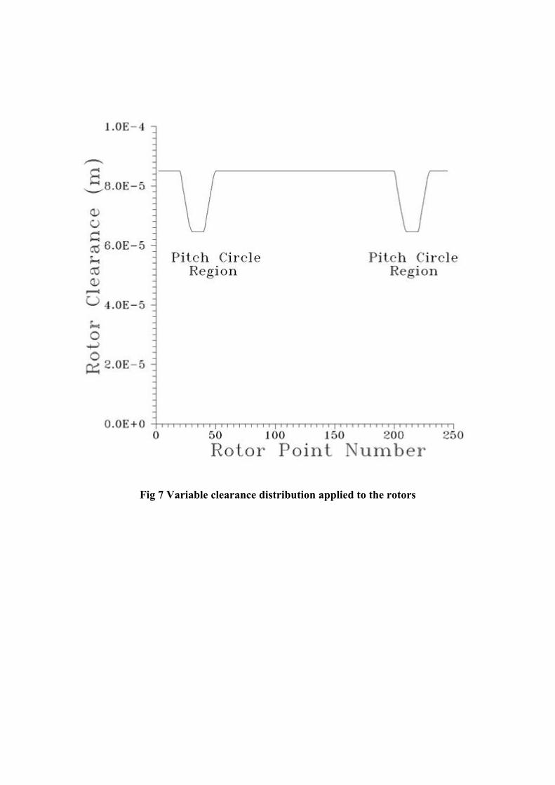
Fig 7 Variable clearance distribution applied to the rotors

a) Cold rotors b) Rotor contact on the round face c) Contact on the flat face
Figure 8 Interlobe clearance distribution
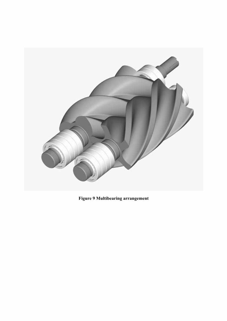
Figure 9 Multibearing arrangement

Figure 10 Small screw compressor based on 35 mm 4-5 rotors, displacement 30 ccm/rev
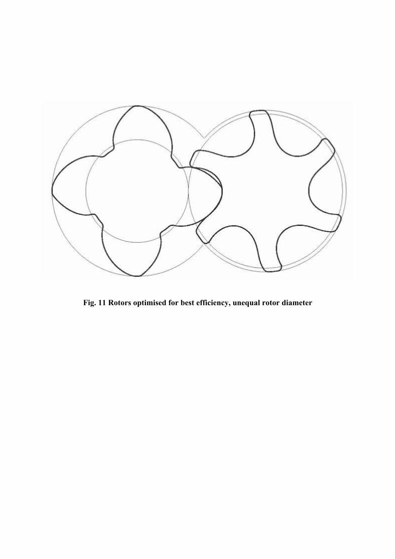
Fig. 11 Rotors optimised for best efficiency, unequal rotor diameter

Fig. 12 Screw compressor rotors optimised for air conditioning and light refrigeration duty,
left and rotors designed for heavy refrigeration duty, right

Figure 13 Original rotors and compressor optimised for general refrigeration and air condition duty

Fig. 14 Compressor and retrofit rotors optimised for general refrigeration duty compared with the original rotors, light line

Figure 15 View of the multifunctional rotors acting simultaneously as compressor and expander in a screw machine

Figure 16 Compressor-Expander rotors sealed from both sides

Figure 17 Screw machine for simultaneous compression and expansion

Figure 18 The ‘Expressor’ principle and the first prototype machine

Figure 19 Layout of a two stage compressor utilizing one pair of screw rotors

Figure 20 Semihermetic compressor with motor cooling through superfeed port at the motor housing, far right

Figure 21 Layout of the multirotor screw compressor presented by Sakun, 1960