Embed Size (px)
Citation preview
Physicochemical Problems of Mineral Processing, 41 (2007), 237-249 Fizykochemiczne Problemy Mineralurgii, 41 (2007), 237-249 Piotr WODZIŃSKI*
SCREENS – CLASSIFICATION AND SYSTEMATICS SINGLE-PLANE SCREENS
Received April 2, 2007; reviewed; accepted May 17, 2007
A classification of screens, which covers structures applied in industry, and also new solutions of highly efficient high-tech screens tested in pilot-plant scale is presented in the paper. The last screen classification published in literature comes from Wessel (1963) and is not valid any longer. Therefore, in this paper a new classification of screens is shown which includes the latest achievements in this field and excludes old screens that are not offered by machinery producers any longer.
In the construction of screening machines there are certain design solutions which have been considered the most appropriate now. In the case of screens with a linear flow of screened material through the machine, these are the screens with a drive with two synchronised rotary vibrators. The construction enables different trajectories of riddle vibrations. In the case of spiral flow of screened material on the sieve, there are wobbling caisson screens which actually have dominated this machine class.
Other screening machines constitute small part of all produced screens and complete the two main classes mentioned above. All most important screening machines used in the national economy of a developed country will be presented in this paper.
Key words: sieve, screen, sieve motion trajectory, granular material, particle classification
INTRODUCTION
The process of screening granular materials was known most probably in ancient
times already. The first published description of this process comes from the 17th century. In the 19th and 20th century a rapid progress of screening techniques and screens was observed [Banaszewski, 1990; Dietrych, 1962; Sztaba, 1993]. The present development of screens is on a stabilised level. In most cases machine building industry produces similar machines on a related technical level. Differences in the structure of individual screens of the same type are small and refer to details. Hence, they do not determine the suitability of particular machines for screening processes. * Łódź Technical University, W-10; K-101, ul. Wólczańska 175, 90-924 Łódź, Poland.
P. Wodziński
238
The main criterion of the presented screen classification was a screen sieve motion. The motion of a vibrating sieve determines the process run, because on this depends the motion of grains in the screened layer and grain transfer through the mesh (Wodziński, 1997). The second important element which characterises a screen is the type of flow of a screened medium through the screen or the trajectory of grains on the sieve. Here, two basic resultant trajectories of grains moving on a sieve surface are distinguished: linear and spiral. The first one refers to the screens with rectangular sieves and cubicoid riddle. The second type covers cylindrical sieves and spiral motion of grains from the centre to the sieve edge. There are, however, a few exceptions to this classification.
CLASSIFICATION OF SCREENING MACHINES
SCREENS
Moving sieves Immobile sieves
Immobile riddles
Gravitational screens
Flow screens
Moving riddles
Rectangular riddles Membrane sieves
Cylindrical riddles
Surging sieves
The above classification of screens is relatively simple and covers majority (in fact
all) machines for industrial screening of granular materials. Further in this study we will discuss subsequent single-plane screens, i.e. such whose riddles along with the sieves perform plane motion in the principal plane of the machine.
SINGLE-PLANE SCREENS
This is undoubtedly the biggest subgroup of screening machines. It is estimated
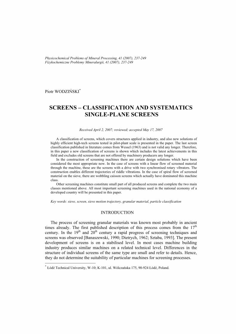
that about 70 to 80% of presently built screens are the single-plane machines. Figure 1 shows possible component motions of the screen with a rectangular riddle. A reference system is the Cartesian system of solid axes (0xyz) (Fig. 1); the centre of the
Screens – classification and systematics
239
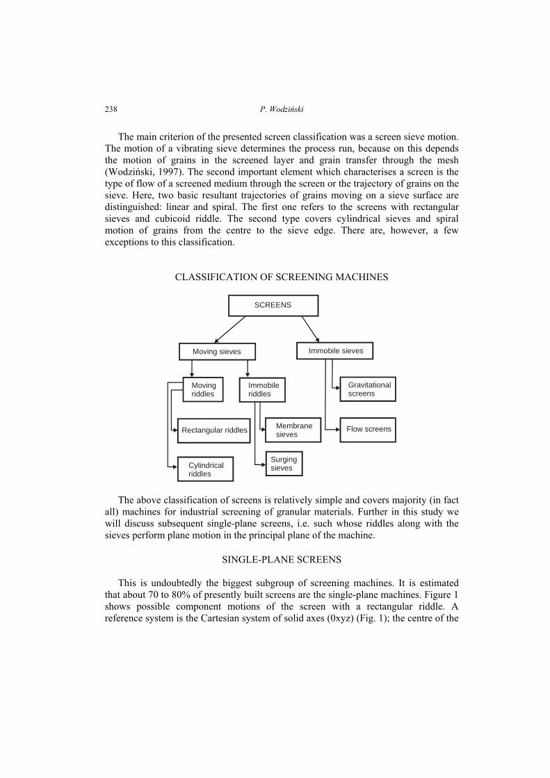
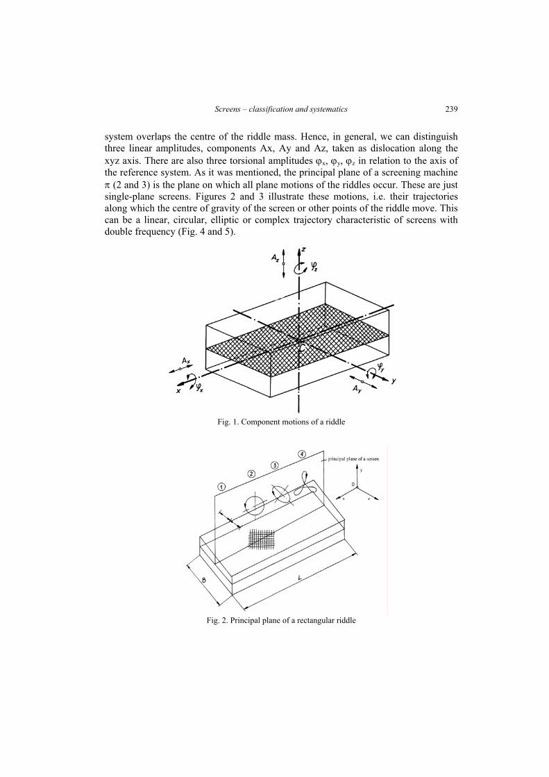
system overlaps the centre of the riddle mass. Hence, in general, we can distinguish three linear amplitudes, components Ax, Ay and Az, taken as dislocation along the xyz axis. There are also three torsional amplitudes ϕx, ϕy, ϕz in relation to the axis of the reference system. As it was mentioned, the principal plane of a screening machine π (2 and 3) is the plane on which all plane motions of the riddles occur. These are just single-plane screens. Figures 2 and 3 illustrate these motions, i.e. their trajectories along which the centre of gravity of the screen or other points of the riddle move. This can be a linear, circular, elliptic or complex trajectory characteristic of screens with double frequency (Fig. 4 and 5).
Fig. 1. Component motions of a riddle
Fig. 2. Principal plane of a rectangular riddle
P. Wodziński
240
Fig. 3. Sieve-riddle motion trajectories in the principal plane π
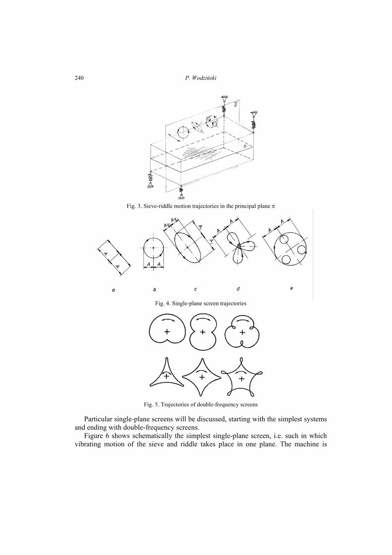
Fig. 4. Single-plane screen trajectories
Fig. 5. Trajectories of double-frequency screens
Particular single-plane screens will be discussed, starting with the simplest systems
and ending with double-frequency screens. Figure 6 shows schematically the simplest single-plane screen, i.e. such in which
vibrating motion of the sieve and riddle takes place in one plane. The machine is
Screens – classification and systematics
241
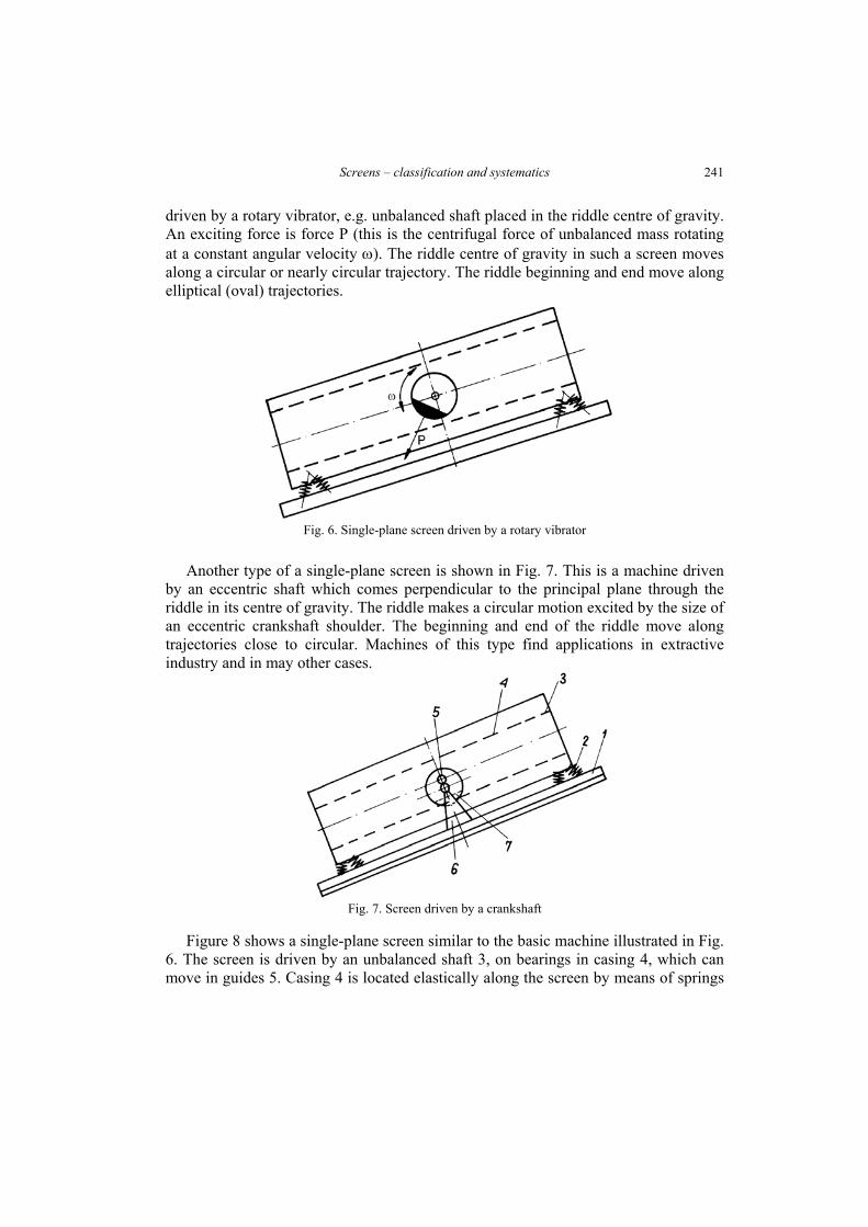
driven by a rotary vibrator, e.g. unbalanced shaft placed in the riddle centre of gravity. An exciting force is force P (this is the centrifugal force of unbalanced mass rotating at a constant angular velocity ω). The riddle centre of gravity in such a screen moves along a circular or nearly circular trajectory. The riddle beginning and end move along elliptical (oval) trajectories.
Fig. 6. Single-plane screen driven by a rotary vibrator
Another type of a single-plane screen is shown in Fig. 7. This is a machine driven
by an eccentric shaft which comes perpendicular to the principal plane through the riddle in its centre of gravity. The riddle makes a circular motion excited by the size of an eccentric crankshaft shoulder. The beginning and end of the riddle move along trajectories close to circular. Machines of this type find applications in extractive industry and in may other cases.
Fig. 7. Screen driven by a crankshaft
Figure 8 shows a single-plane screen similar to the basic machine illustrated in Fig.
6. The screen is driven by an unbalanced shaft 3, on bearings in casing 4, which can move in guides 5. Casing 4 is located elastically along the screen by means of springs
P. Wodziński
242
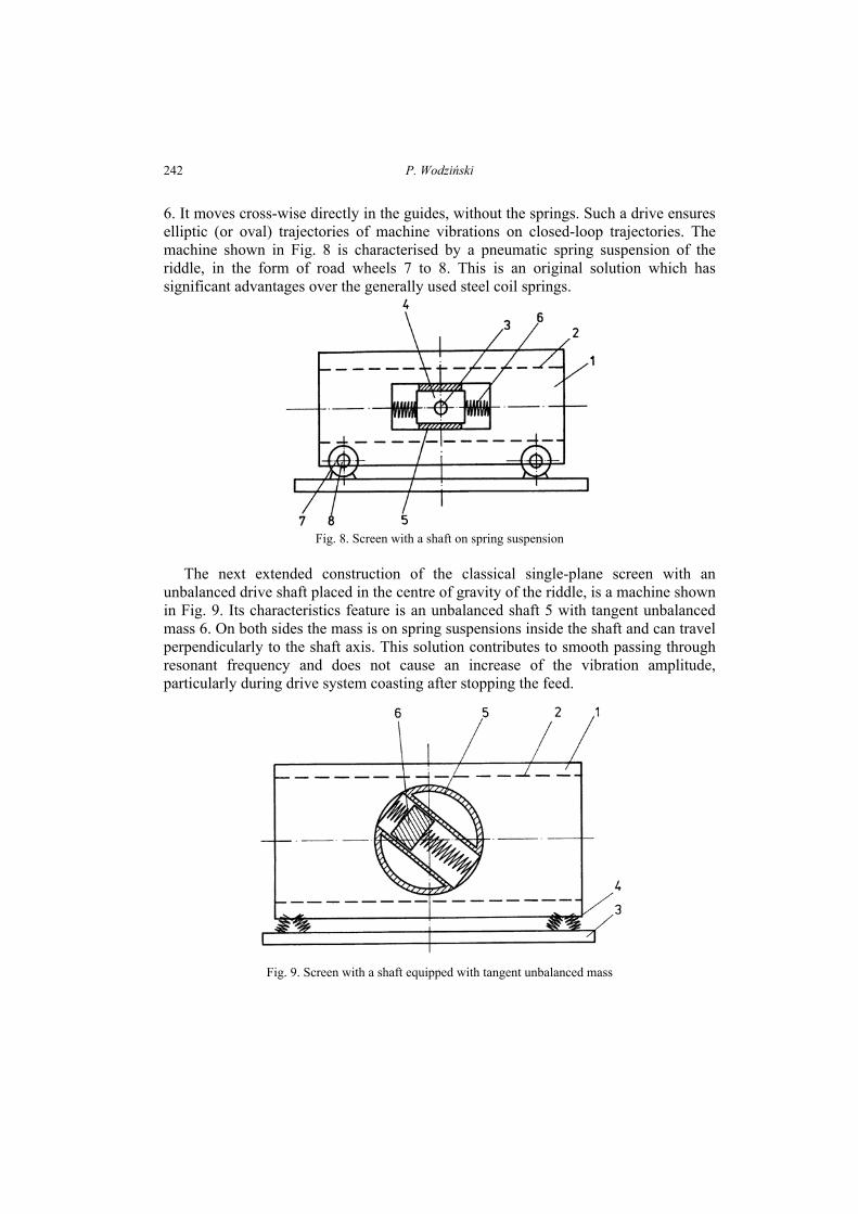
6. It moves cross-wise directly in the guides, without the springs. Such a drive ensures elliptic (or oval) trajectories of machine vibrations on closed-loop trajectories. The machine shown in Fig. 8 is characterised by a pneumatic spring suspension of the riddle, in the form of road wheels 7 to 8. This is an original solution which has significant advantages over the generally used steel coil springs.
Fig. 8. Screen with a shaft on spring suspension
The next extended construction of the classical single-plane screen with an
unbalanced drive shaft placed in the centre of gravity of the riddle, is a machine shown in Fig. 9. Its characteristics feature is an unbalanced shaft 5 with tangent unbalanced mass 6. On both sides the mass is on spring suspensions inside the shaft and can travel perpendicularly to the shaft axis. This solution contributes to smooth passing through resonant frequency and does not cause an increase of the vibration amplitude, particularly during drive system coasting after stopping the feed.
Fig. 9. Screen with a shaft equipped with tangent unbalanced mass
Screens – classification and systematics
243
A big group of single-plane screens consists of screens driven by biaxial rotary vibrators. A rotary vibrator is the vibrator with an unbalanced shaft put in uniform rotary motion which induces centrifugal force that is the driving force, i.e. the force which excites vibrations of the riddle. If there are two unbalanced shafts with parallel axes in the drive, then we have a rotary biaxial vibrator. It is important to obtain a synchronised rotary motion of these shafts which can be achieved in three ways: • using a toothed gear that combines both shafts, • applying a cogbelt gearing, • by obtaining the effect of dynamic self-synchronisation of these shafts in the
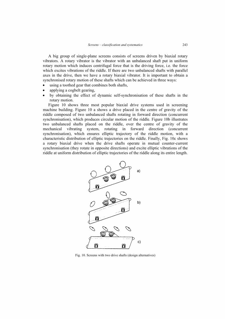
rotary motion. Figure 10 shows three most popular biaxial drive systems used in screening
machine building. Figure 10 a shows a drive placed in the centre of gravity of the riddle composed of two unbalanced shafts rotating in forward direction (concurrent synchronisation), which produces circular motion of the riddle. Figure 10b illustrates two unbalanced shafts placed on the riddle, over the centre of gravity of the mechanical vibrating system, rotating in forward direction (concurrent synchronisation), which ensures elliptic trajectory of the riddle motion, with a characteristic distribution of elliptic trajectories on the riddle. Finally, Fig. 10c shows a rotary biaxial drive when the drive shafts operate in mutual counter-current synchronisation (they rotate in opposite directions) and excite elliptic vibrations of the riddle at uniform distribution of elliptic trajectories of the riddle along its entire length.
Fig. 10. Screens with two drive shafts (design alternatives)
P. Wodziński
244
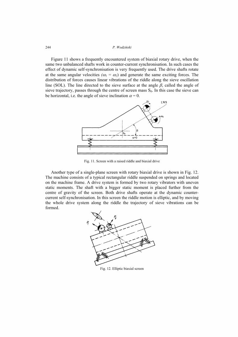
Figure 11 shows a frequently encountered system of biaxial rotary drive, when the same two unbalanced shafts work in counter-current synchronisation. In such cases the effect of dynamic self-synchronisation is very frequently used. The drive shafts rotate at the same angular velocities (ω1 = ω2) and generate the same exciting forces. The distribution of forces causes linear vibrations of the riddle along the sieve oscillation line (SOL). The line directed to the sieve surface at the angle β, called the angle of sieve trajectory, passes through the centre of screen mass S0. In this case the sieve can be horizontal, i.e. the angle of sieve inclination α = 0.
Fig. 11. Screen with a raised riddle and biaxial drive
Another type of a single-plane screen with rotary biaxial drive is shown in Fig. 12.
The machine consists of a typical rectangular riddle suspended on springs and located on the machine frame. A drive system is formed by two rotary vibrators with uneven static moments. The shaft with a bigger static moment is placed further from the centre of gravity of the screen. Both drive shafts operate at the dynamic counter-current self-synchronisation. In this screen the riddle motion is elliptic, and by moving the whole drive system along the riddle the trajectory of sieve vibrations can be formed.
Fig. 12. Elliptic biaxial screen
Screens – classification and systematics
245
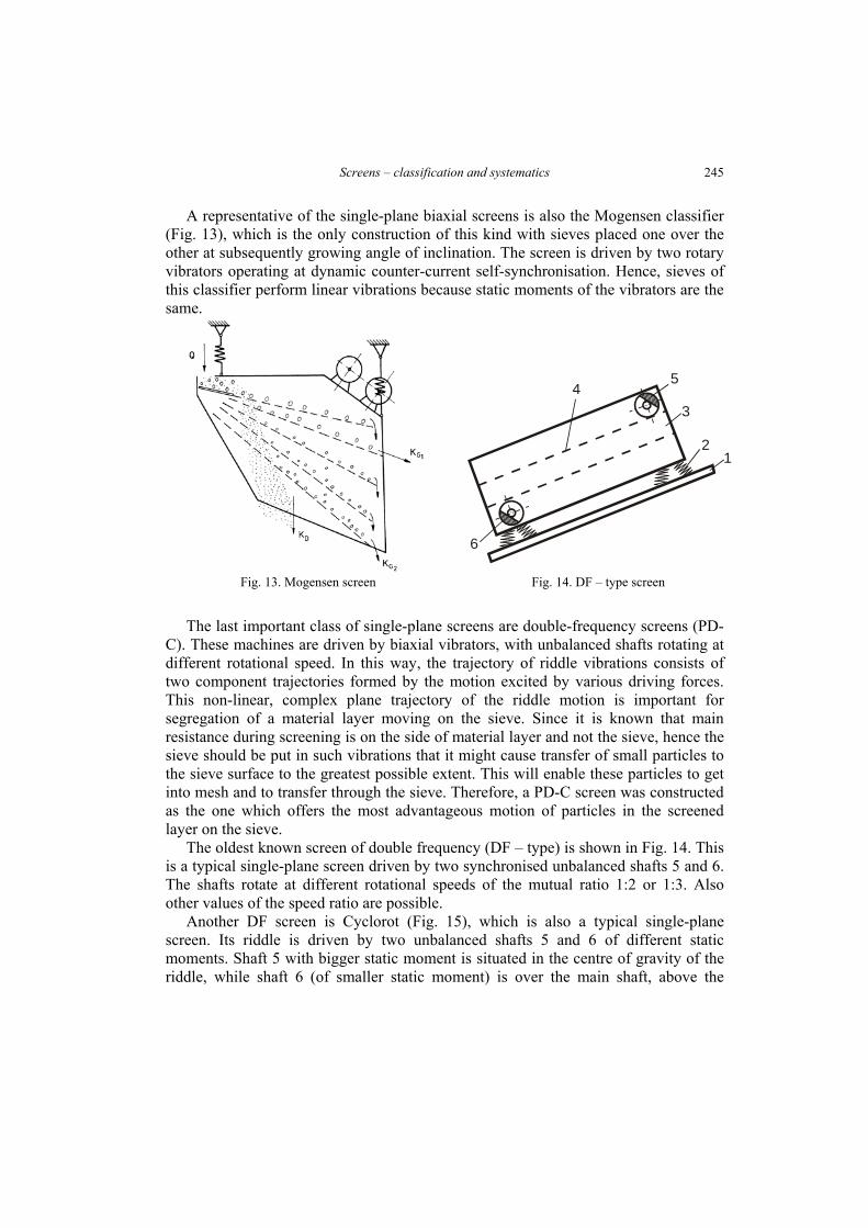
A representative of the single-plane biaxial screens is also the Mogensen classifier (Fig. 13), which is the only construction of this kind with sieves placed one over the other at subsequently growing angle of inclination. The screen is driven by two rotary vibrators operating at dynamic counter-current self-synchronisation. Hence, sieves of this classifier perform linear vibrations because static moments of the vibrators are the same.
5
3
21
6
4
Fig. 13. Mogensen screen Fig. 14. DF – type screen
The last important class of single-plane screens are double-frequency screens (PD-C). These machines are driven by biaxial vibrators, with unbalanced shafts rotating at different rotational speed. In this way, the trajectory of riddle vibrations consists of two component trajectories formed by the motion excited by various driving forces. This non-linear, complex plane trajectory of the riddle motion is important for segregation of a material layer moving on the sieve. Since it is known that main resistance during screening is on the side of material layer and not the sieve, hence the sieve should be put in such vibrations that it might cause transfer of small particles to the sieve surface to the greatest possible extent. This will enable these particles to get into mesh and to transfer through the sieve. Therefore, a PD-C screen was constructed as the one which offers the most advantageous motion of particles in the screened layer on the sieve.
The oldest known screen of double frequency (DF – type) is shown in Fig. 14. This is a typical single-plane screen driven by two synchronised unbalanced shafts 5 and 6. The shafts rotate at different rotational speeds of the mutual ratio 1:2 or 1:3. Also other values of the speed ratio are possible.
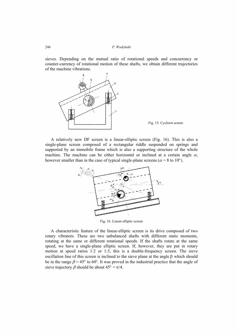
Another DF screen is Cyclorot (Fig. 15), which is also a typical single-plane screen. Its riddle is driven by two unbalanced shafts 5 and 6 of different static moments. Shaft 5 with bigger static moment is situated in the centre of gravity of the riddle, while shaft 6 (of smaller static moment) is over the main shaft, above the
P. Wodziński
246
sieves. Depending on the mutual ratio of rotational speeds and concurrency or counter-currency of rotational motion of these shafts, we obtain different trajectories of the machine vibrations.
Fig. 15. Cyclorot screen
A relatively new DF screen is a linear-elliptic screen (Fig. 16). This is also a
single-plane screen composed of a rectangular riddle suspended on springs and supported by an immobile frame which is also a supporting structure of the whole machine. The machine can be either horizontal or inclined at a certain angle α, however smaller than in the case of typical single-plane screens (α = 8 to 10°).
Fig. 16. Linear-elliptic screen
A characteristic feature of the linear-elliptic screen is its drive composed of two
rotary vibrators. These are two unbalanced shafts with different static moments, rotating at the same or different rotational speeds. If the shafts rotate at the same speed, we have a single-plane elliptic screen. If, however, they are put in rotary motion at speed ratios 1:2 or 1:3, this is a double-frequency screen. The sieve oscillation line of this screen is inclined to the sieve plane at the angle β which should be in the range β = 45° to 60°. It was proved in the industrial practice that the angle of sieve trajectory β should be about 45° = π/4.
Screens – classification and systematics
247
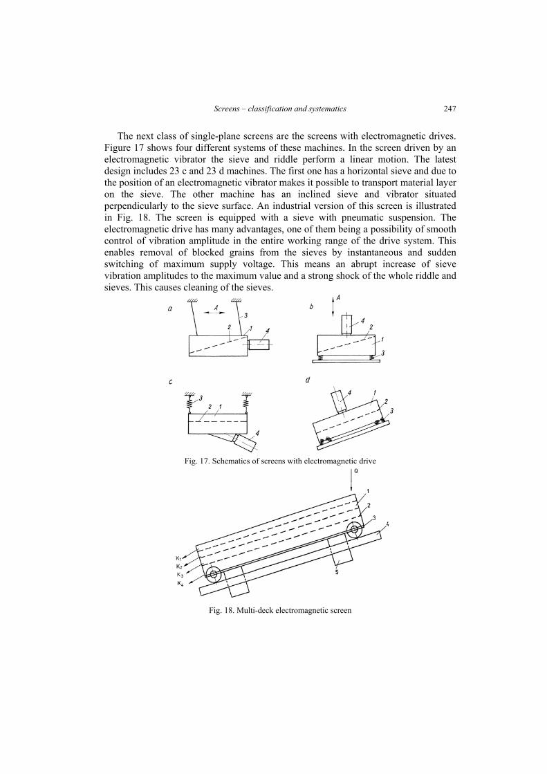
The next class of single-plane screens are the screens with electromagnetic drives. Figure 17 shows four different systems of these machines. In the screen driven by an electromagnetic vibrator the sieve and riddle perform a linear motion. The latest design includes 23 c and 23 d machines. The first one has a horizontal sieve and due to the position of an electromagnetic vibrator makes it possible to transport material layer on the sieve. The other machine has an inclined sieve and vibrator situated perpendicularly to the sieve surface. An industrial version of this screen is illustrated in Fig. 18. The screen is equipped with a sieve with pneumatic suspension. The electromagnetic drive has many advantages, one of them being a possibility of smooth control of vibration amplitude in the entire working range of the drive system. This enables removal of blocked grains from the sieves by instantaneous and sudden switching of maximum supply voltage. This means an abrupt increase of sieve vibration amplitudes to the maximum value and a strong shock of the whole riddle and sieves. This causes cleaning of the sieves.
Fig. 17. Schematics of screens with electromagnetic drive
Fig. 18. Multi-deck electromagnetic screen
P. Wodziński
248
PROCESS PARAMETERS OF SINGLE-PLANE SCREENS
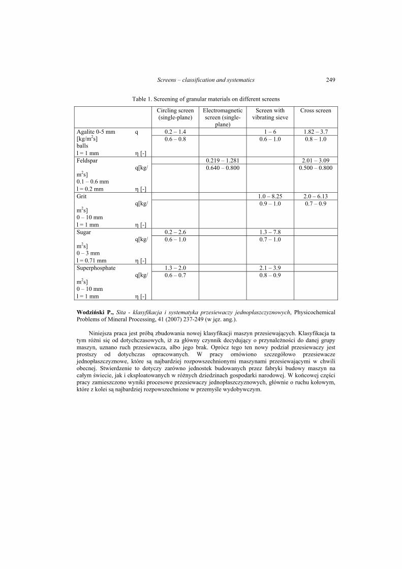
Process parameters of single-plane screens will be presented and a comparison with membrane screens and cross screens will be made (Table1). In all cases woven metal sieves (steel, brass and chrome-nickel) were used. These are results obtained by the author .
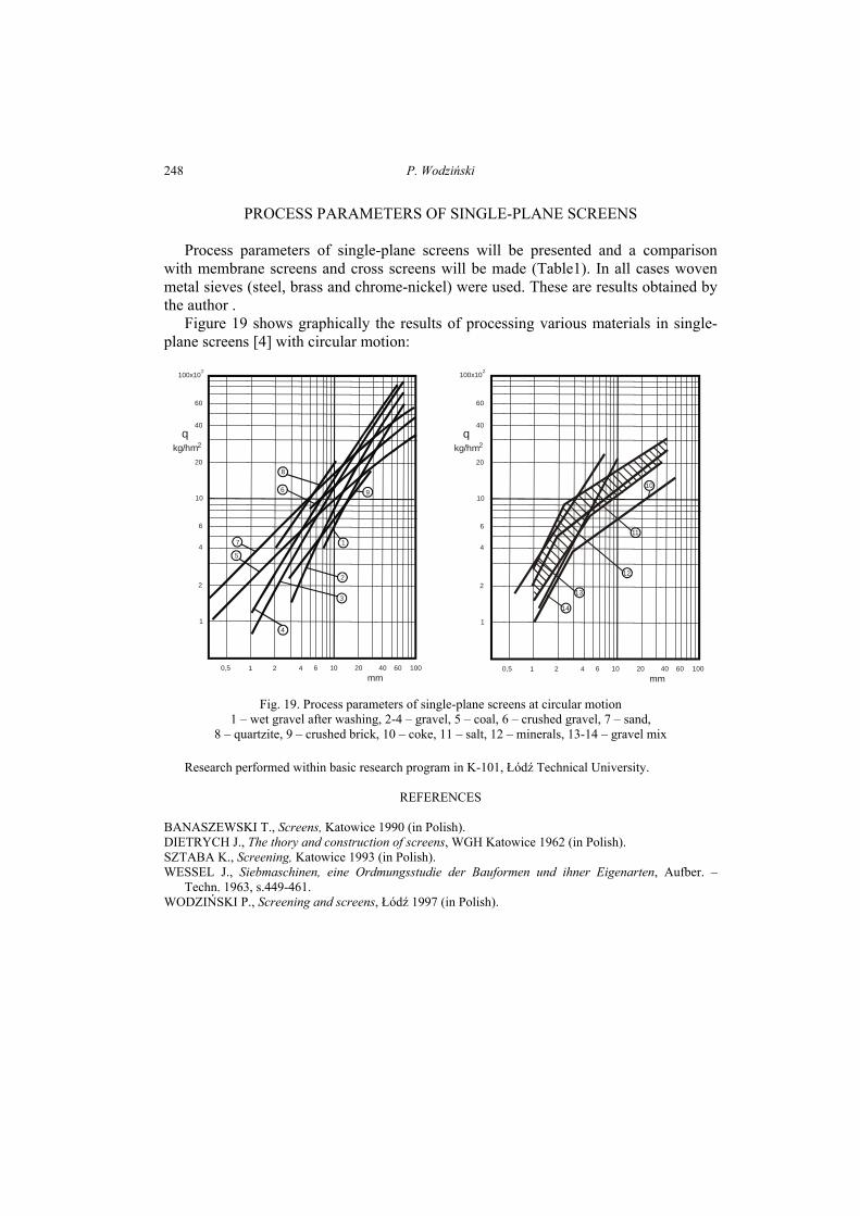
Figure 19 shows graphically the results of processing various materials in single-plane screens [4] with circular motion:
8
6
7
5
9
1
2
3
4
100x102
10
20
40
60
6
4
2
1
0,5 1 2 4 6 10 20 40 60 100mm
q kg/hm2
100x102
10
20
40
60
6
4
2
1
0,5 1 2 4 6 10 20 40 60 100mm
q kg/hm2
10
11
12
13
14
Fig. 19. Process parameters of single-plane screens at circular motion 1 – wet gravel after washing, 2-4 – gravel, 5 – coal, 6 – crushed gravel, 7 – sand,
8 – quartzite, 9 – crushed brick, 10 – coke, 11 – salt, 12 – minerals, 13-14 – gravel mix
Research performed within basic research program in K-101, Łódź Technical University.
REFERENCES
BANASZEWSKI T., Screens, Katowice 1990 (in Polish). DIETRYCH J., The thory and construction of screens, WGH Katowice 1962 (in Polish). SZTABA K., Screening, Katowice 1993 (in Polish). WESSEL J., Siebmaschinen, eine Ordmungsstudie der Bauformen und ihner Eigenarten, Aufber. –
Techn. 1963, s.449-461. WODZIŃSKI P., Screening and screens, Łódź 1997 (in Polish).
Screens – classification and systematics
249
Table 1. Screening of granular materials on different screens
Circling screen (single-plane)
Electromagnetic screen (single-
plane)
Screen with vibrating sieve
Cross screen
0.2 – 1.4 1 – 6 1.82 – 3.7 Agalite 0-5 mm q [kg/m2s] balls l = 1 mm η [-]
0.6 – 0.8 0.6 – 1.0 0.8 – 1.0
0.219 – 1.281 2.01 – 3.09 Feldspar q[kg/m2s] 0.1 – 0.6 mm l = 0.2 mm η [-]
0.640 – 0.800 0.500 – 0.800
1.0 – 8.25 2.0 – 6.13 Grit q[kg/m2s] 0 – 10 mm l = 1 mm η [-]
0.9 – 1.0 0.7 – 0.9
0.2 – 2.6 1.3 – 7.8 Sugar q[kg/m2s] 0 – 3 mm l = 0.71 mm η [-]
0.6 – 1.0 0.7 – 1.0
1.3 – 2.0 2.1 – 3.9 Superphosphate q[kg/m2s] 0 – 10 mm l = 1 mm η [-]
0.6 – 0.7 0.8 – 0.9
Wodziński P., Sita - klasyfikacja i systematyka przesiewaczy jednopłaszczyznowych, Physicochemical Problems of Mineral Processing, 41 (2007) 237-249 (w jęz. ang.).
Niniejsza praca jest próbą zbudowania nowej klasyfikacji maszyn przesiewających. Klasyfikacja ta tym różni się od dotychczasowych, iż za główny czynnik decydujący o przynależności do danej grupy maszyn, uznano ruch przesiewacza, albo jego brak. Oprócz tego ten nowy podział przesiewaczy jest prostszy od dotychczas opracowanych. W pracy omówiono szczegółowo przesiewacze jednopłaszczyznowe, które są najbardziej rozpowszechnionymi maszynami przesiewającymi w chwili obecnej. Stwierdzenie to dotyczy zarówno jednostek budowanych przez fabryki budowy maszyn na całym świecie, jak i eksploatowanych w różnych dziedzinach gospodarki narodowej. W końcowej części pracy zamieszczono wyniki procesowe przesiewaczy jednopłaszczyznowych, głównie o ruchu kołowym, które z kolei są najbardziej rozpowszechnione w przemyśle wydobywczym.