Embed Size (px)
Citation preview
— A B B M E A SU R EM ENT & A N A LY TI C S | TECH N I C A L DE SCR I P TI O N
ScreenMaster RVG200Paperless recorder
Online prediction of the optimum coagulant dosage for potable water treatment using the RVG200 paperless recorder
Measurement made easy
—Introduction
All life requires water to survive. From plants to human beings, water consumption is vital to maintain good health and prolong life. However, water is also home to smaller organisms and contamination such as bacteria and viruses, some of which can be detrimental to the health of the organisms that may be consuming the water.
The World Health Organization (WHO) are responsible for providing a set of general standards of water quality that are followed in countries where better local standards are not implemented.
Developed countries, such as those in Europe, have vigorous standards in place for drinking water that mean the quality of water is high enough that it can be drunk directly from the tap (faucet).
Potable or drinking water treatment involves the removal of contaminants from raw water to produce water that is pure enough for human consumption without any long- or short-term effects on human health as a result of that consumption. The type of substances that must be removed are viruses, bacteria, algae, fungus and suspended solids. Certain minerals (for example, iron and manganese) must also be removed as high concentrations are harmful if consumed.
This Technical Description focuses on using ABB’s RVG200 paperless recorder to perform online coagulant dose prediction in a water treatment plant using the following product build:
RVG200.A6.A6.H6.Y0.*.0.*.*.*.A.*.*.Y–N1.N2.N5.
It explains why this process is important and details how to configure the recorder.
—Online prediction of coagulation dosage for potable water treatment
2 S CR E E N M A S TE R RVG 2 0 0 PA PER L E SS R ECO R D ER | TD/R an d C/0 2 1- EN R E V. A
—What is coagulation?
Coagulation is the term used when referring to the action or process of a liquid (for example, blood), changing to a solid or semi solid state. The initial stages of water treatment involve the removal of solids from the water.
Large debris or trash is first removed from the water by a screen. Other large non-floating debris is then separated from the water by gravity. However, not all solids in the water are large enough to be removed in this way. It is at this point that coagulation is employed as the next step in removing the solids.
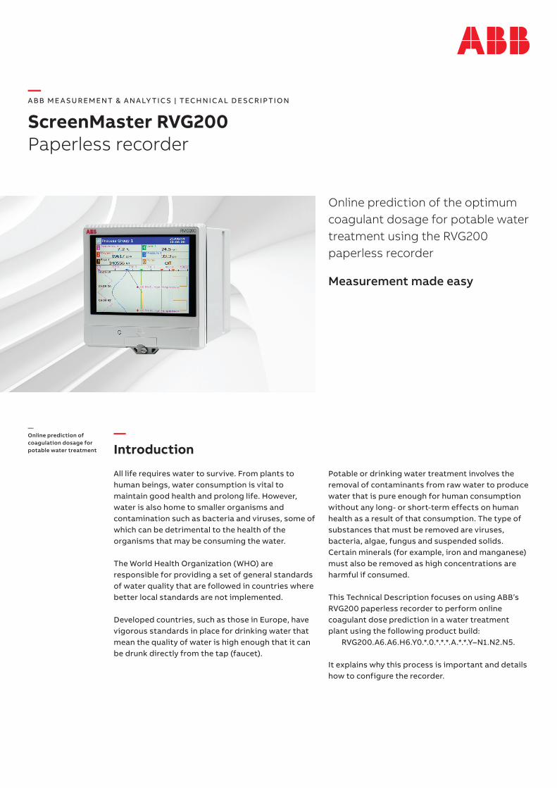
In terms of water treatment, coagulation is a process that involves the addition of a chemical to the water that causes the smaller particles to clump together to form larger aggregates that can then be removed more easily. This chemical, normally a metallic salt such as iron or aluminium, has a positive electrical charge that is the opposite to the negative charge on the particles that are suspended in the water. Rapid mixing ensures the chemical dissolves and is distributed evenly throughout the water.
The introduction of the opposing electrical charge neutralizes the negative charge on the particles causing them to stick together, thus forming larger particles. The water then flows into another tank where it is stirred very slowly to bring the particles together and form large particles or ‘flocs’. This step is called flocculation.
Coagulationtank
Mixingtank
Flocculationtank
Raw water
source
Debris
Pumping station
Pre-chlorination Flocculant
Sedimentationtank
Sand and sludge
Coagulant
Travellingscreen
Measurement of water color and
turbidity
Measurement of water color and
possibly turbidity
FC
AI TI FI U
FC FC
The coagulation process
3S CR E E N M A S TE R RVG 2 0 0 PA PER L E SS R ECO R D ER | TD/R an d C/0 2 1- EN R E V. A
—Coagulant dose prediction
The purpose of a coagulant dosing system is to calculate and dispense the optimum amount of the coagulant to facilitate the chemical process and allow the particulates to become big enough to be removed from the water through the processes of sedimentation and filtration. It does this by using a series of measurements that are fed through a pre-configured equation that uses the instantaneous values of water color, turbidity, flow, pH and a number of operator set ‘K’ (constant) values. These are based on the pre-treatment water quality and coagulant being used, to calculate the dose demand:
(K1 × raw color) + (K2 × raw turbidity) + K3 + pH trim + clarified color trim
Where:K1 = color contribution factor*K2 = turbidity contribution factor*K3 = base coagulation doseK4 = coagulant type factor
When calculated, the dose demand is used in a further equation:
dose demand × flow × K4/1440
This calculates the actual required dose rate in l/m that is used subsequently to control a coagulant dosing pump in the system.
Note. The ‘K ‘ values are supplied by the water treatment customer and are unique to every installation.
*Contribution factor is defined as a multiplication factor that determines
contribution to the overall required amount of coagulant
—Water color measurement
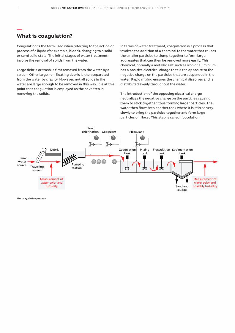
Colorimetry or colorimetric chemistry is a method of measuring the concentration of a sample based on the absorption of light, of a particular wave length, that can be measured and converted to a concentration value of the light absorbing substances within the sample. The amount of light absorbed in this type of measurement varies in accordance with the Beer-Lambert Law that defines a simple linear relationship between the absorption of light of a sample and the concentration of that sample. In the case of water treatment, coagulant dosage adjustment is based on the natural color of the water. This is used to measure the smallest of particles or dissolution of chemicals that cannot be detected with the naked eye. The more particles contained within the water the cloudier it will be and the more light it absorbs.
Concentration (mg/l)
Ab
sorb
ance
0.1
0.0
0.2
0.4
0.6
0.8
0 0.2 0.3 0.4
Beer-Lambert Law graph
AW637 color analyzer
4 S CR E E N M A S TE R RVG 2 0 0 PA PER L E SS R ECO R D ER | TD/R an d C/0 2 1- EN R E V. A
—Turbidity measurement
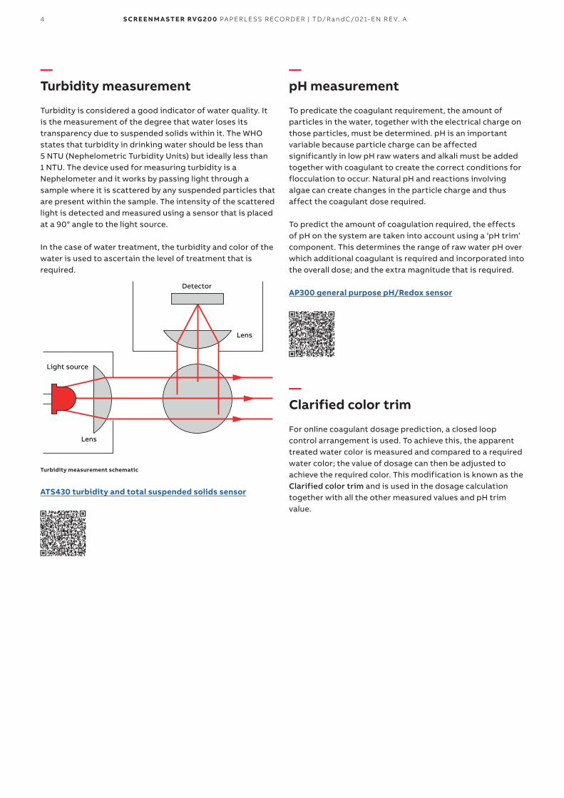
Turbidity is considered a good indicator of water quality. It is the measurement of the degree that water loses its transparency due to suspended solids within it. The WHO states that turbidity in drinking water should be less than 5 NTU (Nephelometric Turbidity Units) but ideally less than 1 NTU. The device used for measuring turbidity is a Nephelometer and it works by passing light through a sample where it is scattered by any suspended particles that are present within the sample. The intensity of the scattered light is detected and measured using a sensor that is placed at a 90° angle to the light source.
In the case of water treatment, the turbidity and color of the water is used to ascertain the level of treatment that is required.
Light source
Lens
Lens
Detector
Turbidity measurement schematic
ATS430 turbidity and total suspended solids sensor
—pH measurement
To predicate the coagulant requirement, the amount of particles in the water, together with the electrical charge on those particles, must be determined. pH is an important variable because particle charge can be affected significantly in low pH raw waters and alkali must be added together with coagulant to create the correct conditions for flocculation to occur. Natural pH and reactions involving algae can create changes in the particle charge and thus affect the coagulant dose required.
To predict the amount of coagulation required, the effects of pH on the system are taken into account using a ‘pH trim’ component. This determines the range of raw water pH over which additional coagulant is required and incorporated into the overall dose; and the extra magnitude that is required.
AP300 general purpose pH/Redox sensor
—Clarified color trim
For online coagulant dosage prediction, a closed loop control arrangement is used. To achieve this, the apparent treated water color is measured and compared to a required water color; the value of dosage can then be adjusted to achieve the required color. This modification is known as the Clarified color trim and is used in the dosage calculation together with all the other measured values and pH trim value.
5S CR E E N M A S TE R RVG 2 0 0 PA PER L E SS R ECO R D ER | TD/R an d C/0 2 1- EN R E V. A
—Configuring the RVG200
Configuration of the RVG200 begins in the same way as any other process. The number of process groups, the individual physical inputs and associated alarms are all configured as for a standard recorder to the requirements of the process.
For the coagulation prediction application, the following physical analog inputs are required:
• raw water color (analog I/P 1)• raw water turbidity (analog I/P 2)• raw water Flow (analog I/P 3)• raw water pH (analog I/P 4)• clarified water color (analog I/P 5)
…and the following physical digital inputs:• raw color sample status (hybrid digital I/P 2)• clarified color sample status (hybrid digital I/P 3)• maintenance hold (hybrid digital I/P 1)
The recorder’s Math & Logic and custom linearizers are then used to calculate the color and pH trim and the actual dose demand and rate.
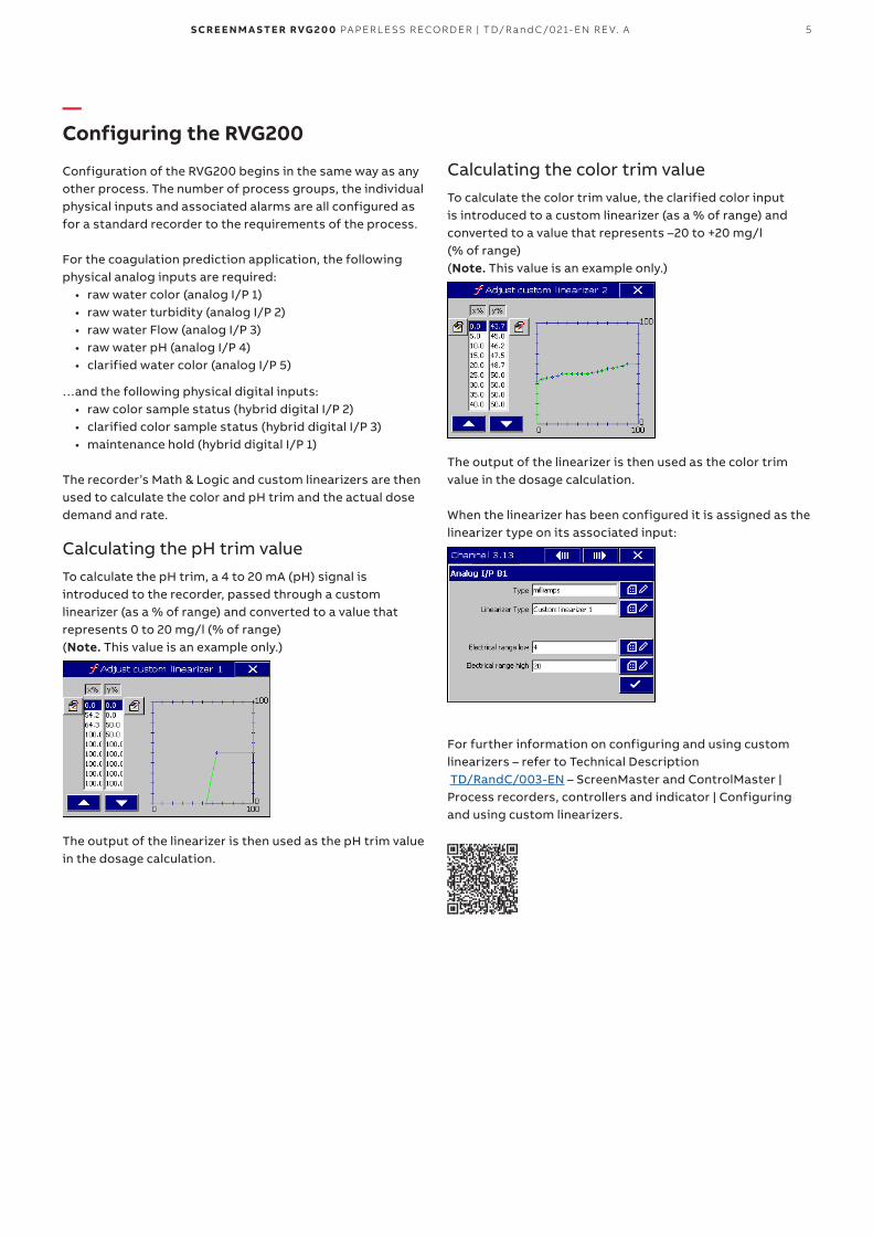
Calculating the pH trim valueTo calculate the pH trim, a 4 to 20 mA (pH) signal is introduced to the recorder, passed through a custom linearizer (as a % of range) and converted to a value that represents 0 to 20 mg/l (% of range) (Note. This value is an example only.)
The output of the linearizer is then used as the pH trim value in the dosage calculation.
Calculating the color trim valueTo calculate the color trim value, the clarified color input is introduced to a custom linearizer (as a % of range) and converted to a value that represents –20 to +20 mg/l (% of range) (Note. This value is an example only.)
The output of the linearizer is then used as the color trim value in the dosage calculation.
When the linearizer has been configured it is assigned as the linearizer type on its associated input:
For further information on configuring and using custom linearizers – refer to Technical Description TD/RandC/003-EN – ScreenMaster and ControlMaster | Process recorders, controllers and indicator | Configuring and using custom linearizers.
6 S CR E E N M A S TE R RVG 2 0 0 PA PER L E SS R ECO R D ER | TD/R an d C/0 2 1- EN R E V. A
—…Configuring the RVG200
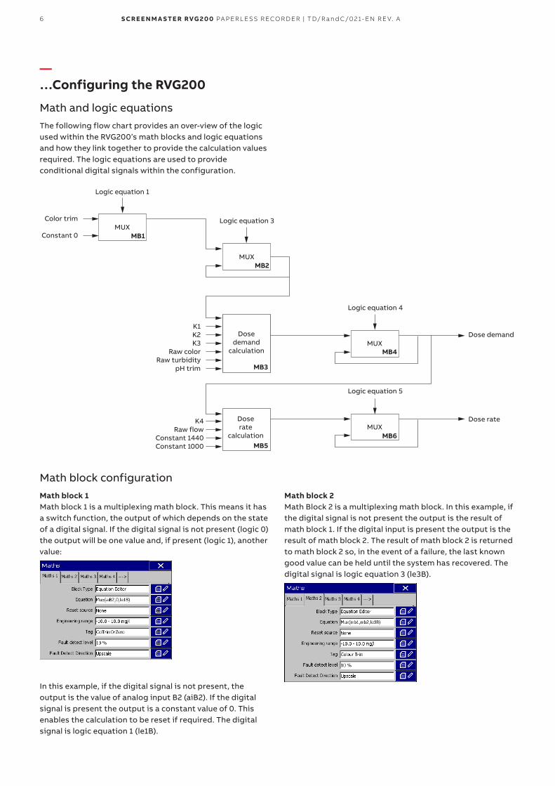
Math and logic equationsThe following flow chart provides an over-view of the logic used within the RVG200’s math blocks and logic equations and how they link together to provide the calculation values required. The logic equations are used to provide conditional digital signals within the configuration.
Logic equation 1
Doserate
calculation
MUX
MUX
MB4
MB6
Dose rate
Dose demand
MB5
Color trim
Constant 0
K1K2K3
Raw colorRaw turbidity
pH trim
K4Raw flow
Constant 1440Constant 1000
Logic equation 3
Logic equation 4
Logic equation 5
MUXMB1
MUXMB2
Dosedemand
calculation
MB3
Math block configurationMath block 1Math block 1 is a multiplexing math block. This means it has a switch function, the output of which depends on the state of a digital signal. If the digital signal is not present (logic 0) the output will be one value and, if present (logic 1), another value:
In this example, if the digital signal is not present, the output is the value of analog input B2 (aiB2). If the digital signal is present the output is a constant value of 0. This enables the calculation to be reset if required. The digital signal is logic equation 1 (le1B).
Math block 2Math Block 2 is a multiplexing math block. In this example, if the digital signal is not present the output is the result of math block 1. If the digital input is present the output is the result of math block 2. The result of math block 2 is returned to math block 2 so, in the event of a failure, the last known good value can be held until the system has recovered. The digital signal is logic equation 3 (le3B).
7S CR E E N M A S TE R RVG 2 0 0 PA PER L E SS R ECO R D ER | TD/R an d C/0 2 1- EN R E V. A
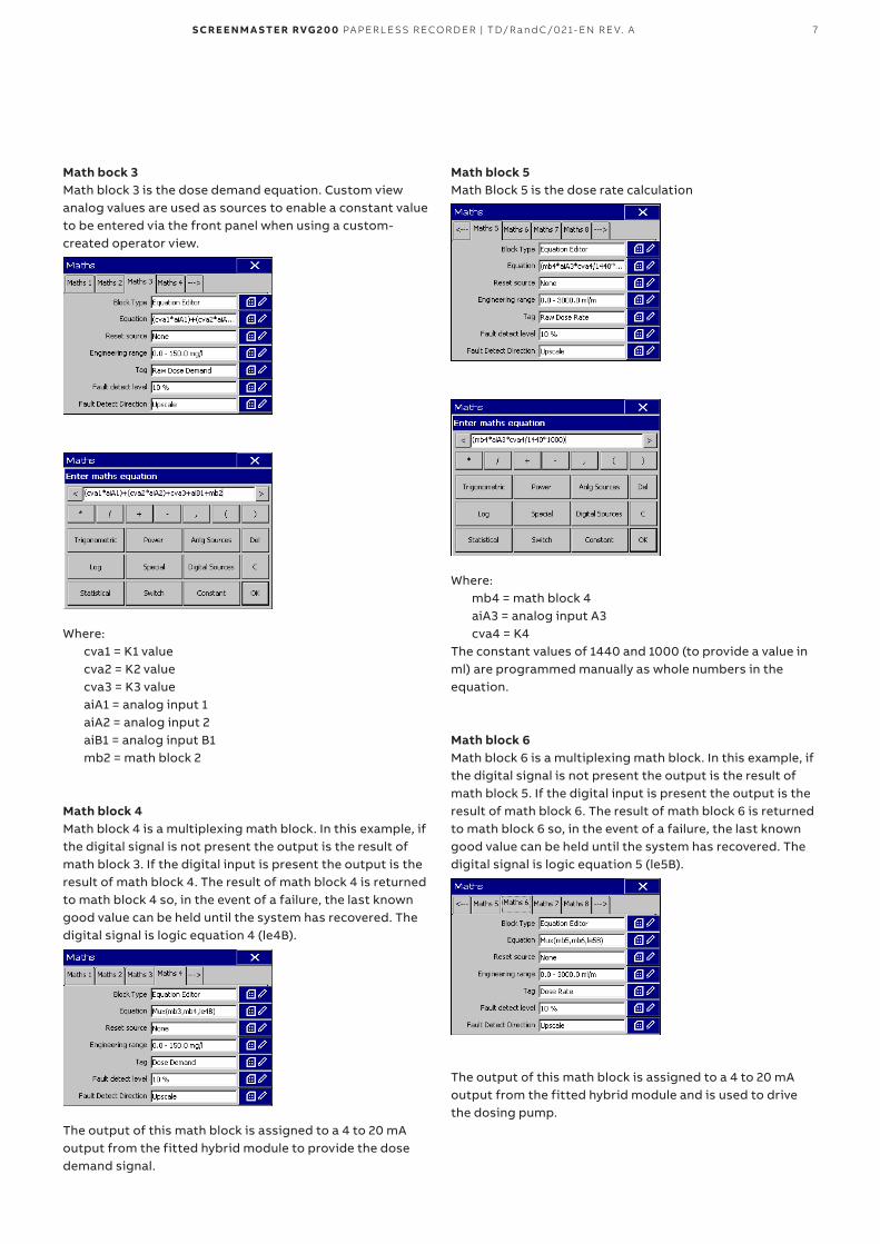
Math bock 3Math block 3 is the dose demand equation. Custom view analog values are used as sources to enable a constant value to be entered via the front panel when using a custom-created operator view.
Where:cva1 = K1 valuecva2 = K2 valuecva3 = K3 valueaiA1 = analog input 1aiA2 = analog input 2aiB1 = analog input B1mb2 = math block 2
Math block 4Math block 4 is a multiplexing math block. In this example, if the digital signal is not present the output is the result of math block 3. If the digital input is present the output is the result of math block 4. The result of math block 4 is returned to math block 4 so, in the event of a failure, the last known good value can be held until the system has recovered. The digital signal is logic equation 4 (le4B).
The output of this math block is assigned to a 4 to 20 mA output from the fitted hybrid module to provide the dose demand signal.
Math block 5Math Block 5 is the dose rate calculation
Where:mb4 = math block 4aiA3 = analog input A3cva4 = K4
The constant values of 1440 and 1000 (to provide a value in ml) are programmed manually as whole numbers in the equation.
Math block 6Math block 6 is a multiplexing math block. In this example, if the digital signal is not present the output is the result of math block 5. If the digital input is present the output is the result of math block 6. The result of math block 6 is returned to math block 6 so, in the event of a failure, the last known good value can be held until the system has recovered. The digital signal is logic equation 5 (le5B).
The output of this math block is assigned to a 4 to 20 mA output from the fitted hybrid module and is used to drive the dosing pump.
8 S CR E E N M A S TE R RVG 2 0 0 PA PER L E SS R ECO R D ER | TD/R an d C/0 2 1- EN R E V. A
—…Configuring the RVG200
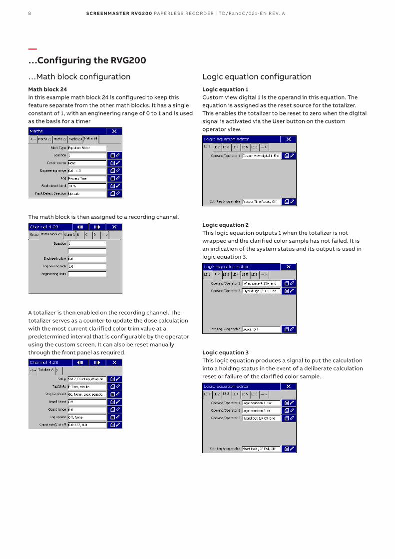
…Math block configurationMath block 24In this example math block 24 is configured to keep this feature separate from the other math blocks. It has a single constant of 1, with an engineering range of 0 to 1 and is used as the basis for a timer
The math block is then assigned to a recording channel.
A totalizer is then enabled on the recording channel. The totalizer serves as a counter to update the dose calculation with the most current clarified color trim value at a predetermined interval that is configurable by the operator using the custom screen. It can also be reset manually through the front panel as required.
Logic equation configurationLogic equation 1Custom view digital 1 is the operand in this equation. The equation is assigned as the reset source for the totalizer. This enables the totalizer to be reset to zero when the digital signal is activated via the User button on the custom operator view.
Logic equation 2This logic equation outputs 1 when the totalizer is not wrapped and the clarified color sample has not failed. It is an indication of the system status and its output is used in logic equation 3.
Logic equation 3This logic equation produces a signal to put the calculation into a holding status in the event of a deliberate calculation reset or failure of the clarified color sample.
9S CR E E N M A S TE R RVG 2 0 0 PA PER L E SS R ECO R D ER | TD/R an d C/0 2 1- EN R E V. A
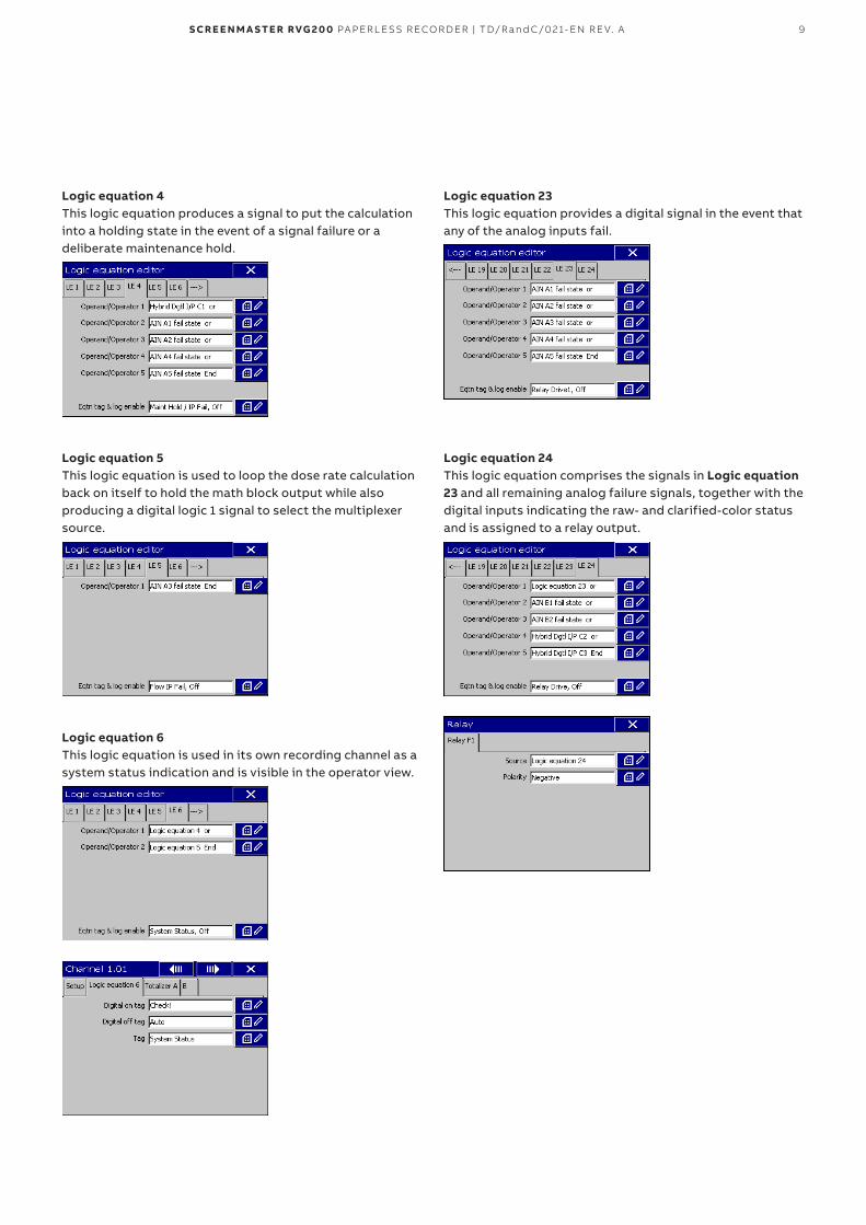
Logic equation 4This logic equation produces a signal to put the calculation into a holding state in the event of a signal failure or a deliberate maintenance hold.
Logic equation 5This logic equation is used to loop the dose rate calculation back on itself to hold the math block output while also producing a digital logic 1 signal to select the multiplexer source.
Logic equation 6This logic equation is used in its own recording channel as a system status indication and is visible in the operator view.
Logic equation 23This logic equation provides a digital signal in the event that any of the analog inputs fail.
Logic equation 24This logic equation comprises the signals in Logic equation 23 and all remaining analog failure signals, together with the digital inputs indicating the raw- and clarified-color status and is assigned to a relay output.
10 S CR E E N M A S TE R RVG 2 0 0 PA PER L E SS R ECO R D ER | TD/R an d C/0 2 1- EN R E V. A
—Custom operator view
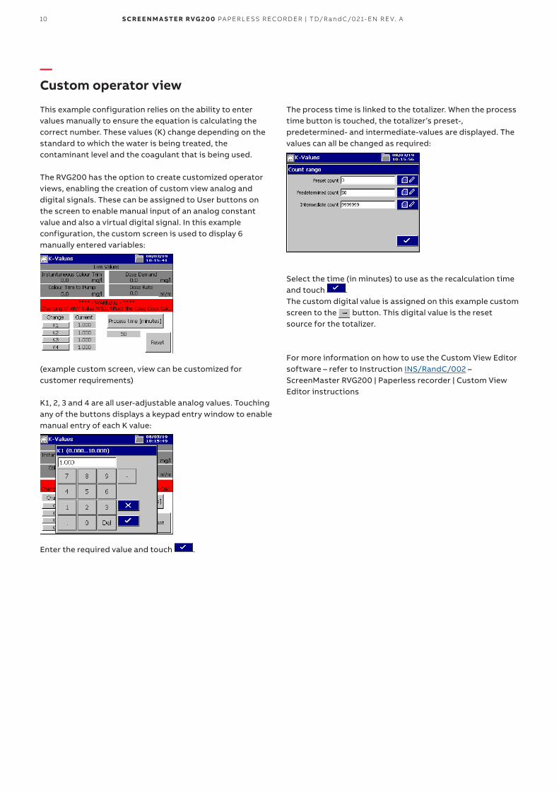
This example configuration relies on the ability to enter values manually to ensure the equation is calculating the correct number. These values (K) change depending on the standard to which the water is being treated, the contaminant level and the coagulant that is being used.
The RVG200 has the option to create customized operator views, enabling the creation of custom view analog and digital signals. These can be assigned to User buttons on the screen to enable manual input of an analog constant value and also a virtual digital signal. In this example configuration, the custom screen is used to display 6 manually entered variables:
(example custom screen, view can be customized for customer requirements)
K1, 2, 3 and 4 are all user-adjustable analog values. Touching any of the buttons displays a keypad entry window to enable manual entry of each K value:
Enter the required value and touch .
The process time is linked to the totalizer. When the process time button is touched, the totalizer’s preset-, predetermined- and intermediate-values are displayed. The values can all be changed as required:
Select the time (in minutes) to use as the recalculation time and touch .The custom digital value is assigned on this example custom screen to the button. This digital value is the reset source for the totalizer.
For more information on how to use the Custom View Editor software – refer to Instruction INS/RandC/002 – ScreenMaster RVG200 | Paperless recorder | Custom View Editor instructions

11S CR E E N M A S TE R RVG 2 0 0 PA PER L E SS R ECO R D ER | TD/R an d C/0 2 1- EN R E V. A
—Analytical measurement
Click on the following link or scan the QR code for more information on the analytical instrumentation that can be used in this application that ABB also manufacture.
Analytical measurement

TD
/Ran
dC
/021
-EN
Rev
. B
07.
2019
—ABB Limited Measurement & Analytics Howard Road, St. Neots Cambridgeshire, PE19 8EU UK Tel: +44 (0)1480 475 321 Fax: +44 (0)1480 217 948 Email: [email protected]
ABB Inc. Measurement & Analytics 125 E. County Line Road Warminster, PA 18974 USA Tel: +1 215 674 6000 Fax: +1 215 674 7183
abb.com/recorders
—We reserve the right to make technical changes or modify the contents of this document without prior notice. With regard to purchase orders, the agreed particulars shall prevail. ABB does not accept any responsibility whatsoever for potential errors or possible lack of information in this document.
We reserve all rights in this document and in the subject matter and illustrations contained therein. Any reproduction, disclosure to third parties or utilization of its contents – in whole or in parts – is forbidden without prior written consent of ABB.
© 2019 ABB.All rights reserved.