Embed Size (px)
Citation preview
1
ac�nnbmbamdmmanmppi
nossaatpcam��qvSr
Jsb
J
Downloa
Shane E. Flores
Michael G. Pontin
Frank W. Zok
Materials Department,University of California,
Santa Barbara, CA 93106
Scratching of Elastic/PlasticMaterials With Hard SphericalIndentersA mechanistic framework has been developed for interpreting scratch tests performedwith spherical indenters on elastic/plastic materials. The pertinent scaling relations havebeen identified through a plastic analysis and the model has been subsequently calibratedby finite element calculations. The results show that the ratio of scratch force to normalforce (or apparent friction coefficient) can be partitioned into two additive components:one due to interfacial friction and another associated with plastic deformation. Theplastic component scales parabolically with the normal force and depends only weaklyon the true (elastic) friction coefficient. A simple formula for the scratch force, based onthe plastic analysis and the numerical results, has been derived. Finally, experimentalmeasurements on two material standards commonly used for nanoindenter calibrationhave been used to verify the theoretical results. �DOI: 10.1115/1.2966268�
IntroductionThe advent of instrumented nanoindenters some two decades
go has enabled an unprecedented capability for probing the me-hanical properties of materials over a wide range of length scalesfrom nm to mm� and forces �from �N to N�. In addition to theirow-routine use in measuring material stiffness and hardness,anoindenters allow studies of creep, dynamic loading, thin filmehavior, fracture, and adhesion. Good summaries of the testethods and the underlying mechanics are presented in textbooks
y Bhushan �1� and Fischer-Cripps �2� as well as a recent reviewrticle by Gouldstone et al. �3�. A comparatively recent advance-ent in the field has been the development of instrumented in-
enter probes that can be displaced in a precise manner both nor-al and tangential to the sample surface. These probes alloweasurement of tribological properties—those involving friction,
brasion, and wear—at length scales and force ranges typical oformal indentation �4–15�. Despite the technological advance-ents, analysis protocols for extracting fundamental material
roperties from such tests have not reached maturity levels com-arable to those used to ascertain modulus and hardness fromndentation tests.
The principal goal of the present article is to outline a mecha-istic framework for interpreting measurements from scratch testsn elastic/plastic materials with spherical indenters. The latterhape selection is motivated by the fact that, at low force levels,tresses beneath a spherical indenter are below the elastic limitsnd hence the tribological properties can be ascertained in thebsence of plasticity; yet, at higher force levels, responses in theransitional elastic/plastic and the fully plastic regimes can also berobed. In contrast, with sharp-tipped indenters such as the cube-orner, Berkovich, and cone, the accessible behavioral domainsre far more restricted. That is, because of the self-similar defor-ation fields associated with sharp tips, the strain level is fixed
independent of normal force� and dictated by indenter shape16–18�. Probing material properties over a range of strains re-uires use of indenters of varying shapes. Even then, if the tips areery sharp, measurements cannot be made in the elastic domain.election of the spherical indenter is further motivated by theecognition that the asperities that make contact during sliding of
Contributed by the Applied Mechanics Division of ASME for publication in theOURNAL OF APPLIED MECHANICS. Manuscript received January 22, 2008; final manu-cript received June 30, 2008; published online August 22, 2008. Review conducted
y Zhigang Suo.ournal of Applied Mechanics Copyright © 20
ded 03 Sep 2008 to 128.111.74.218. Redistribution subject to ASM
surfaces are more closely represented by protuberances with aconstant �finite� curvature rather than ones with infinitely sharppoints.
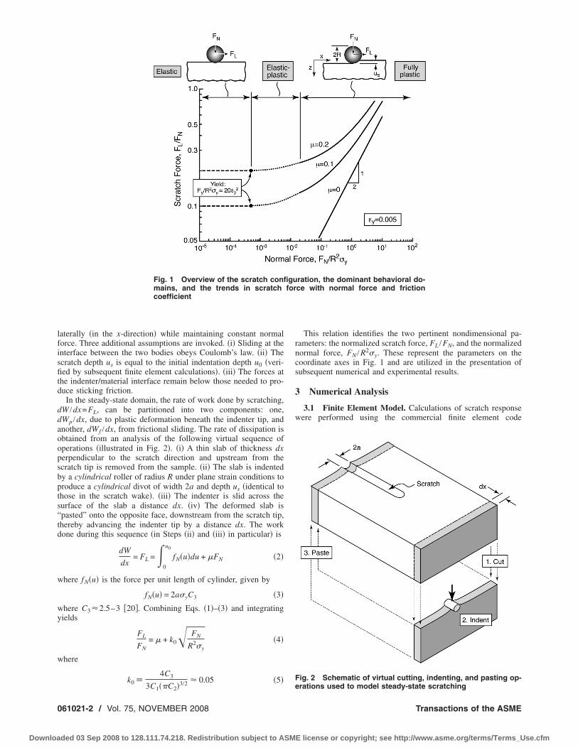
As a prelude to forthcoming results and to provide perspective,the test conditions of interest and the dominant behavioral do-mains are illustrated in Fig. 1. Here a rigid sphere is pressed intocontact with a flat slab of plastically deformable material withnormal force FN and subsequently slid across the slab surface withlateral force FL. At sufficiently low levels of FN, wherein thecontact is elastic, sliding occurs subject to Coulomb’s law, withfriction coefficient ��FL /FN. In contrast, at high force levels,both initial normal contact and subsequent sliding involve plasticdeformation. In this domain, the normalized scratch force �or ap-parent friction coefficient�, FL /FN, increases approximately para-bolically with FN and exceeds the true �elastic� friction coeffi-cient. An intermediate force range exists within whichdeformation involves comparable amounts of elastic and plasticstrains and the curves in Fig. 1 transition accordingly. The highload domain is the main focus of the present article.
The remainder of this article consists of three parts. In the first,an approximate analytical model of scratching of a rigid, perfectlyplastic material based on a virtual work analysis is presented. Themodel is used to identify the scaling relation between the scratchforce and the geometric and material properties �resulting in thenondimensional parameters of the coordinate axes in Fig. 1�.Next, finite element calculations are used to investigate the effectsof normal force and friction coefficient on scratch force, with thegoal of ascertaining the key nondimensional parameters. Finally,experimental measurements on two material standards are pre-sented and compared with the model predictions.
2 Analytical ModelA lower-bound estimate of the scratch force is obtained using
established theorems of classical plasticity. The geometry to beanalyzed is depicted by the schematic in the top right corner ofFig. 1. Scratching proceeds in two steps. First, a rigid sphericalindenter of radius R is pushed into a flat semi-infinite slab of rigid,perfectly plastic material with normal force, FN. The radius, a, ofthe resulting indentation is given by �19�
a = �C1Ru0 =� FN
C2��y�1�
where u0 is the maximum penetration depth, �y is the material
yield strength, C1=2.7, and C2=3.0. The indenter is then movedNOVEMBER 2008, Vol. 75 / 061021-108 by ASME
E license or copyright; see http://www.asme.org/terms/Terms_Use.cfm
lfisfitd
ddaoopsbpts“td
w
wy
w
0
Downloa
aterally �in the x-direction� while maintaining constant normalorce. Three additional assumptions are invoked. �i� Sliding at thenterface between the two bodies obeys Coulomb’s law. �ii� Thecratch depth us is equal to the initial indentation depth u0 �veri-ed by subsequent finite element calculations�. �iii� The forces at
he indenter/material interface remain below those needed to pro-uce sticking friction.
In the steady-state domain, the rate of work done by scratching,W /dx=FL, can be partitioned into two components: one,Wp /dx, due to plastic deformation beneath the indenter tip, andnother, dWf /dx, from frictional sliding. The rate of dissipation isbtained from an analysis of the following virtual sequence ofperations �illustrated in Fig. 2�. �i� A thin slab of thickness dxerpendicular to the scratch direction and upstream from thecratch tip is removed from the sample. �ii� The slab is indentedy a cylindrical roller of radius R under plane strain conditions toroduce a cylindrical divot of width 2a and depth us �identical tohose in the scratch wake�. �iii� The indenter is slid across theurface of the slab a distance dx. �iv� The deformed slab ispasted” onto the opposite face, downstream from the scratch tip,hereby advancing the indenter tip by a distance dx. The workone during this sequence �in Steps �ii� and �iii� in particular� is
dW
dx= FL =�
0
u0
fN�u�du + �FN �2�
here fN�u� is the force per unit length of cylinder, given by
fN�u� = 2a�yC3 �3�
here C3�2.5–3 �20�. Combining Eqs. �1�–�3� and integratingields
FL
FN= � + k0� FN
R2�y�4�
here
k0 �4C3
3/2 � 0.05 �5�
Fig. 1 Overview of the scratch confimains, and the trends in scratchcoefficient
3C1��C2�
61021-2 / Vol. 75, NOVEMBER 2008
ded 03 Sep 2008 to 128.111.74.218. Redistribution subject to ASM
This relation identifies the two pertinent nondimensional pa-rameters: the normalized scratch force, FL /FN, and the normalizednormal force, FN /R2�y. These represent the parameters on thecoordinate axes in Fig. 1 and are utilized in the presentation ofsubsequent numerical and experimental results.
3 Numerical Analysis
3.1 Finite Element Model. Calculations of scratch responsewere performed using the commercial finite element code
ration, the dominant behavioral do-ce with normal force and friction
Fig. 2 Schematic of virtual cutting, indenting, and pasting op-
gufor
erations used to model steady-state scratching
Transactions of the ASME
E license or copyright; see http://www.asme.org/terms/Terms_Use.cfm
A
sasndbi3rttathhndos
tinl
sisc�
a
J
Downloa
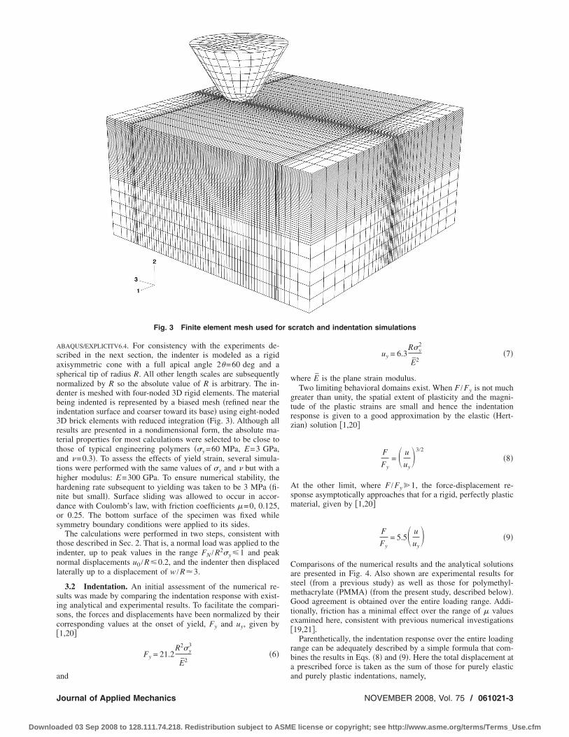
BAQUS/EXPLICITV6.4. For consistency with the experiments de-cribed in the next section, the indenter is modeled as a rigidxisymmetric cone with a full apical angle 2�=60 deg and apherical tip of radius R. All other length scales are subsequentlyormalized by R so the absolute value of R is arbitrary. The in-enter is meshed with four-noded 3D rigid elements. The materialeing indented is represented by a biased mesh �refined near thendentation surface and coarser toward its base� using eight-nodedD brick elements with reduced integration �Fig. 3�. Although allesults are presented in a nondimensional form, the absolute ma-erial properties for most calculations were selected to be close tohose of typical engineering polymers ��y =60 MPa, E=3 GPa,nd �=0.3�. To assess the effects of yield strain, several simula-ions were performed with the same values of �y and � but with aigher modulus: E=300 GPa. To ensure numerical stability, theardening rate subsequent to yielding was taken to be 3 MPa �fi-ite but small�. Surface sliding was allowed to occur in accor-ance with Coulomb’s law, with friction coefficients �=0, 0.125,r 0.25. The bottom surface of the specimen was fixed whileymmetry boundary conditions were applied to its sides.
The calculations were performed in two steps, consistent withhose described in Sec. 2. That is, a normal load was applied to thendenter, up to peak values in the range FN /R2�y �1 and peakormal displacements u0 /R�0.2, and the indenter then displacedaterally up to a displacement of w /R�3.
3.2 Indentation. An initial assessment of the numerical re-ults was made by comparing the indentation response with exist-ng analytical and experimental results. To facilitate the compari-ons, the forces and displacements have been normalized by theirorresponding values at the onset of yield, Fy and uy, given by1,20�
Fy = 21.2R2�y
3
E2�6�
Fig. 3 Finite element mesh used fo
nd
ournal of Applied Mechanics
ded 03 Sep 2008 to 128.111.74.218. Redistribution subject to ASM
uy = 6.3R�y
2
E2�7�
where E is the plane strain modulus.Two limiting behavioral domains exist. When F /Fy is not much
greater than unity, the spatial extent of plasticity and the magni-tude of the plastic strains are small and hence the indentationresponse is given to a good approximation by the elastic �Hert-zian� solution �1,20�
F
Fy= u
uy3/2
�8�
At the other limit, where F /Fy �1, the force-displacement re-sponse asymptotically approaches that for a rigid, perfectly plasticmaterial, given by �1,20�
F
Fy= 5.5 u
uy �9�
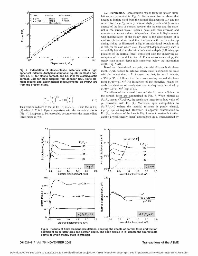
Comparisons of the numerical results and the analytical solutionsare presented in Fig. 4. Also shown are experimental results forsteel �from a previous study� as well as those for polymethyl-methacrylate �PMMA� �from the present study, described below�.Good agreement is obtained over the entire loading range. Addi-tionally, friction has a minimal effect over the range of � valuesexamined here, consistent with previous numerical investigations�19,21�.
Parenthetically, the indentation response over the entire loadingrange can be adequately described by a simple formula that com-bines the results in Eqs. �8� and �9�. Here the total displacement ata prescribed force is taken as the sum of those for purely elastic
cratch and indentation simulations
r sand purely plastic indentations, namely,
NOVEMBER 2008, Vol. 75 / 061021-3
E license or copyright; see http://www.asme.org/terms/Terms_Use.cfm
T��f
Fstcmf
0
Downloa
u
uy= F
Fy2/3
+ 0.18 F
Fy �10�
his relation reduces to that in Eq. �8� as F /Fy→0 and that in Eq.9� when F /Fy �1. Upon comparison with the numerical resultsFig. 4�, it appears to be reasonably accurate over the intermediateorce range as well.
ig. 4 Indentation of elastic-plastic materials with a rigidpherical indenter. Analytical solutions: Eq. „8… for elastic con-act, Eq. „9… for plastic contact, and Eq. „10… for elastic/plasticontact. Data for steel adapted from Johnson †20‡. Finite ele-ent results and experimental measurements on PMMA are
rom the present study.
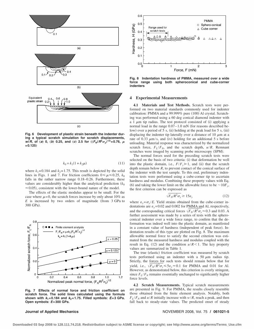
Fig. 5 Results of finite element calculations,coefficient on scratch force and scratch depth
points at which steady state is attained.61021-4 / Vol. 75, NOVEMBER 2008
ded 03 Sep 2008 to 128.111.74.218. Redistribution subject to ASM
3.3 Scratching. Representative results from the scratch simu-lations are presented in Fig. 5. For normal forces above thatneeded to initiate yield, both the normal displacement u /R and thescratch force FL /FN initially increase slightly with w /R �a conse-quence of the loss of contact between the indenter and the mate-rial in the scratch wake�, reach a peak, and then decrease andsaturate at constant values, independent of scratch displacement.One manifestation of the steady state is the development of auniform plastic strain field that translates with the indenter tipduring sliding, as illustrated in Fig. 6. An additional notable resultis that, for the case where �=0, the scratch depth at steady state isessentially identical to the initial indentation depth �following ap-plication of the normal force�, consistent with the underlying as-sumption of the model in Sec. 2. For nonzero values of �, thesteady-state scratch depth falls somewhat below the indentationdepth �Fig. 5�d��.
Based on dimensional analysis, the critical scratch displace-ment, wc /R, needed to achieve steady state is expected to scalewith the indent size, a /R. Recognizing that, for small indents,a /R��u /R, it follows that the corresponding normal displace-ment uc /R� �wc /R�2. An inspection of the numerical results re-veals that the onset of steady state can be adequately described byuc /R�0.1�wc /R�2 �Fig. 5�b��.
The effects of the normal force and the friction coefficient onthe scratch force are summarized in Fig. 7. When plotted asFL /FN versus �FN /R2�y, the results are linear for a fixed value of�, consistent with Eq. �4�. Moreover, upon extrapolation toFN /R2�y =0 �where the material response is purely elastic�,FL /FN→�, as required. However, in apparent contradiction toEq. �4�, the slopes of the lines in Fig. 7 are not constant but ratherexhibit a weak �nearly linear� dependence on �, characterized by
wing the effects of normal force and frictionhe open circles in „b… denote the approximate
sho. T
Transactions of the ASME
E license or copyright; see http://www.asme.org/terms/Terms_Use.cfm
wlfv�
cE3
Fiw=
FssO
J
Downloa
k0 = k1�1 + k2�� �11�
here k1=0.184 and k2=1.75. This result is depicted by the solidines in Figs. 1 and 7. For friction coefficients 0���0.25, k0alls in the rather narrow range 0.18–0.26. Furthermore, thesealues are considerably higher than the analytical prediction �k00.05�, consistent with the lower-bound nature of the model.The effects of the elastic modulus appear to be small. For the
ase where �=0, the scratch forces increase by only about 10% asis increased by two orders of magnitude �from 3 GPa to
00 GPa�.
ig. 6 Development of plastic strain beneath the indenter dur-ng a typical scratch simulation for scratch displacements,
/R, of „a… 0, „b… 0.25, and „c… 2.5 for „„FN /R2�y…1/2=0.76, �
0.125…
ig. 7 Effects of normal force and friction coefficient oncratch force. The solid lines calculated using the formulahown with k1=0.184 and k2=1.75. Filled symbols: E=3 GPa.
pen symbols: E=300 GPa.ournal of Applied Mechanics
ded 03 Sep 2008 to 128.111.74.218. Redistribution subject to ASM
4 Experimental Measurements
4.1 Materials and Test Methods. Scratch tests were per-formed on two material standards commonly used for indentercalibration: PMMA and a 99.999% pure �100� Al crystal. Scratch-ing was performed using a 60 deg conical diamond indenter witha 1 �m tip radius. The test protocol consisted of �i� applying anormal load in the range 0.07–1.0 mN �for reasons described be-low� over a period of 5 s, �ii� holding at the peak load for 5 s, �iii�displacing the indenter tip laterally over a distance of 10 �m at arate of 0.33 �m /s, and �iv� holding for an additional 5 s beforeunloading. Material response was characterized by the normalizedscratch force, FL /FN, and the scratch depth, u /R. Remnantscratches were imaged by scanning probe microscopy �SPM�.
The normal forces used for the preceding scratch tests wereselected on the basis of two criteria: �i� that deformation be wellinto the plastic domain, i.e., F /Fy �1, and �ii� that the scratchdepth remain below R, to prevent contact of the conical surface ofthe indenter with the test sample. To this end, preliminary inden-tation tests were performed using a cube-corner tip to ascertainhardness and modulus. Combining these property values with Eq.�6� and taking the lower limit on the allowable force to be �10Fy,the first criterion can be expressed as
�FN/R2�y 15y �12�
where y =�y /E. Yield strains obtained from the cube-corner in-dentations are y =0.02 and 0.002 for PMMA and Al, respectively,and the corresponding critical forces �FN /R2�y �0.3 and 0.03. Afurther assessment was made by a series of tests with the sphero-conical indenter over a wide force range, to confirm that the de-formation was indeed well into the plastic domain, as manifestedin a constant value of hardness �independent of peak force�. In-dentation results of this type are plotted on Fig. 8. The maximumallowable normal force to satisfy the second criterion was esti-mated from the measured hardness and modulus coupled with theresult in Eq. �12� and the condition u /R�1. The key propertyvalues are summarized in Table 1.
The true �elastic� friction coefficient was measured by scratchtests performed using an indenter with a 50 �m radius tip.Strictly, the forces for such tests should remain below that foryield, i.e., �FN /R2�y �5y �0.1 for PMMA and 0.01 for Al.However, as demonstrated below, this criterion is overly stringent,since FL /FN remains essentially unchanged to significantly higherforce levels.
4.2 Scratch Measurements. Typical scratch measurementsare presented in Fig. 9. For PMMA, the results closely resemblethose obtained from the finite element analysis. Notably, bothFL /FN and u /R initially increase with w /R, reach a peak, and then
Fig. 8 Indentation hardness of PMMA, measured over a wideforce range using both spheroconical and cube-cornerindenters
fall back to steady-state values. The predicted onset of steady
NOVEMBER 2008, Vol. 75 / 061021-5
E license or copyright; see http://www.asme.org/terms/Terms_Use.cfm
smtssFw
aiaucap
1al0alt1tfiri
Y
a
b
0
Downloa
tate, given by uc /R�0.1�wc /R�2, agrees well with the measure-ents. Once at steady state, FL /FN and u /R exhibit minimal fluc-
uations. Although similar features are obtained with the Alample, the reductions in FL /FN and u /R from their peaks to theirteady-state values are considerably greater. Furthermore, bothL /FN and u /R exhibit periodic fluctuations with w /R, withavelengths that increase with FN.The differences in steady-state response of the two materials
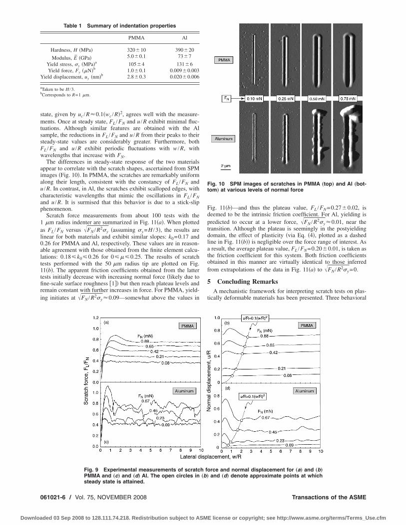
ppear to correlate with the scratch shapes, ascertained from SPMmages �Fig. 10�. In PMMA, the scratches are remarkably uniformlong their length, consistent with the constancy of FL /FN and/R. In contrast, in Al, the scratches exhibit scalloped edges, withharacteristic wavelengths that mimic the oscillations in FL /FNnd u /R. It is surmised that this behavior is due to a stick-sliphenomenon.
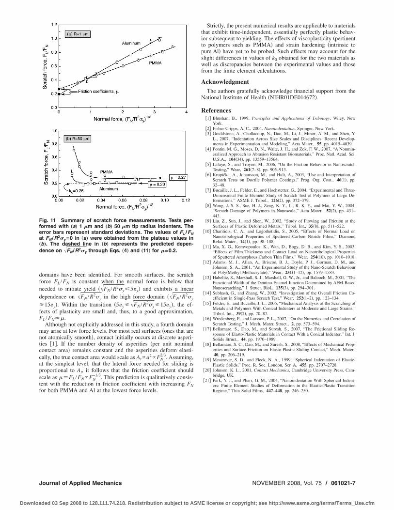
Scratch force measurements from about 100 tests with the�m radius indenter are summarized in Fig. 11�a�. When plotted
s FL /FN versus �FN /R2�y �assuming �y =H /3�, the results areinear for both materials and exhibit similar slopes: k0=0.17 and.26 for PMMA and Al, respectively. These values are in reason-ble agreement with those obtained from the finite element calcu-ations: 0.18�k0�0.26 for 0���0.25. The results of scratchests performed with the 50 �m radius tip are plotted on Fig.1�b�. The apparent friction coefficients obtained from the latterests initially decrease with increasing normal force �likely due tone-scale surface roughness �1�� but then reach plateau levels andemain constant with further increases in force. For PMMA, yield-ng initiates at �FN /R2�y �0.09—somewhat above the values in
Table 1 Summary of indentation properties
PMMA Al
Hardness, H �MPa� 320�10 390�20
Modulus, E �GPa� 5.0�0.1 73�7
Yield stress, �y �MPa�a 105�4 131�6Yield force, Fy ��N�b 1.0�0.1 0.009�0.003
ield displacement, uy �nm�b 2.8�0.3 0.020�0.006
Taken to be H /3.Corresponds to R=1 �m.
Fig. 9 Experimental measurements of scratcPMMA and „c… and „d… Al. The open circles in
steady state is attained.61021-6 / Vol. 75, NOVEMBER 2008
ded 03 Sep 2008 to 128.111.74.218. Redistribution subject to ASM
Fig. 11�b�—and thus the plateau value, FL /FN=0.27�0.02, isdeemed to be the intrinsic friction coefficient. For Al, yielding ispredicted to occur at a lower force, �FN /R2�y �0.01, near thetransition. Although the plateau is seemingly in the postyieldingdomain, the effect of plasticity �via Eq. �4�, plotted as a dashedline in Fig. 11�b�� is negligible over the force range of interest. Asa result, the average plateau value, FL /FN=0.20�0.01, is taken asthe friction coefficient for this system. Both friction coefficientsobtained in this manner are virtually identical to those inferredfrom extrapolations of the data in Fig. 11�a� to �FN /R2�y =0.
5 Concluding RemarksA mechanistic framework for interpreting scratch tests on plas-
tically deformable materials has been presented. Three behavioral
rce and normal displacement for „a… and „b…and „d… denote approximate points at which
Fig. 10 SPM images of scratches in PMMA „top… and Al „bot-tom… at various levels of normal force
h fo„b…
Transactions of the ASME
E license or copyright; see http://www.asme.org/terms/Terms_Use.cfm
dfnd fF
mntccapstf
Ffea„
d
J
Downloa
omains have been identified. For smooth surfaces, the scratchorce FL /FN is constant when the normal force is below thateeded to initiate yield ��FN /R2�y �5y� and exhibits a linearependence on �FN /R2�y in the high force domain ��FN /R2�y
15y�. Within the transition �5y ��FN /R2�y �15y�, the ef-ects of plasticity are small and, thus, to a good approximation,L /FN��.Although not explicitly addressed in this study, a fourth domainay arise at low force levels. For most real surfaces �ones that are
ot atomically smooth�, contact initially occurs at discrete asperi-ies �1�. If the number density of asperities �per unit nominalontact area� remains constant and the asperities deform elasti-ally, the true contact area would scale as At�a2�FN
2/3. Assuming,t the simplest level, that the lateral force needed for sliding isroportional to At, it follows that the friction coefficient shouldcale as ��FL /FN�FN
−1/3. This prediction is qualitatively consis-ent with the reduction in friction coefficient with increasing FNor both PMMA and Al at the lowest force levels.
ig. 11 Summary of scratch force measurements. Tests per-ormed with „a… 1 �m and „b… 50 �m tip radius indenters. Therror bars represent standard deviations. The values of FL /FNt FN /R2�y=0 in „a… were obtained from the plateau values inb…. The dashed line in „b… represents the predicted depen-ence on �FN /R2�y through Eqs. „4… and „11… for �=0.2.
ournal of Applied Mechanics
ded 03 Sep 2008 to 128.111.74.218. Redistribution subject to ASM
Strictly, the present numerical results are applicable to materialsthat exhibit time-independent, essentially perfectly plastic behav-ior subsequent to yielding. The effects of viscoplasticity �pertinentto polymers such as PMMA� and strain hardening �intrinsic topure Al� have yet to be probed. Such effects may account for theslight differences in values of k0 obtained for the two materials aswell as discrepancies between the experimental values and thosefrom the finite element calculations.
AcknowledgmentThe authors gratefully acknowledge financial support from the
National Institute of Health �NIHR01DE014672�.
References�1� Bhushan, B., 1999, Principles and Applications of Tribology, Wiley, New
York.�2� Fisher-Cripps, A. C., 2004, Nanoindentation, Springer, New York.�3� Gouldstone, A., Chollacoop, N., Dao, M., Li, J., Minor, A. M., and Shen, Y.
L., 2007, “Indentation Across Size Scales and Disciplines: Recent Develop-ments in Experimentation and Modeling,” Acta Mater., 55, pp. 4015–4039.
�4� Pontin, M. G., Moses, D. N., Waite, J. H., and Zok, F. W., 2007, “A Nonmin-eralized Approach to Abrasion Resistant Biomaterials,” Proc. Natl. Acad. Sci.U.S.A., 104�34�, pp. 13559–13564.
�5� Lafaye, S., and Troyon, M., 2006, “On the Friction Behavior in NanoscratchTesting,” Wear, 261�7–8�, pp. 905–913.
�6� Krupička, A., Johansson, M., and Hult, A., 2003, “Use and Interpretation ofScratch Tests on Ductile Polymer Coatings,” Prog. Org. Coat., 46�1�, pp.32–48.
�7� Bucaille, J. L., Felder, E., and Hochstetter, G., 2004, “Experimental and Three-Dimensional Finite Element Study of Scratch Test of Polymers at Large De-formations,” ASME J. Tribol., 126�2�, pp. 372–379.
�8� Wong, J. S. S., Sue, H. J., Zeng, K. Y., Li, R. K. Y., and Mai, Y. W., 2004,“Scratch Damage of Polymers in Nanoscale,” Acta Mater., 52�2�, pp. 431–443.
�9� Liu, Z., Sun, J., and Shen, W., 2002, “Study of Plowing and Friction at theSurfaces of Plastic Deformed Metals,” Tribol. Int., 35�8�, pp. 511–522.
�10� Charitidis, C. A., and Logothetidis, S., 2005, “Effects of Normal Load onNanotribological Properties of Sputtered Carbon Nitride Films,” DiamondRelat. Mater., 14�1�, pp. 98–108.
�11� Ma, X. G., Komvopoulos, K., Wan, D., Bogy, D. B., and Kim, Y. S., 2003,“Effects of Film Thickness and Contact Load on Nanotribological Propertiesof Sputtered Amorphous Carbon Thin Films,” Wear, 254�10�, pp. 1010–1018.
�12� Adams, M. J., Allan, A., Briscoe, B. J., Doyle, P. J., Gorman, D. M., andJohnson, S. A., 2001, “An Experimental Study of the Nano-Scratch Behaviourof Poly�Methyl Methacrylate�,” Wear, 251�1–12�, pp. 1579–1583.
�13� Habelitz, S., Marshall, S. J., Marshall, G. W., Jr., and Balooch, M., 2001, “TheFunctional Width of the Dentino-Enamel Junction Determined by AFM-BasedNanoscratching,” J. Struct. Biol., 135�3�, pp. 294–301.
�14� Subhash, G., and Zhang, W., 2002, “Investigation of the Overall Friction Co-efficient in Single-Pass Scratch Test,” Wear, 252�1–2�, pp. 123–134.
�15� Felder, E., and Bucaille, J. L., 2006, “Mechanical Analysis of the Scratching ofMetals and Polymers With Conical Indenters at Moderate and Large Strains,”Tribol. Int., 39�2�, pp. 70–87.
�16� Wredenberg, F., and Larsson, P. L., 2007, “On the Numerics and Correlation ofScratch Testing,” J. Mech. Mater. Struct., 2, pp. 573–594.
�17� Bellamare, S., Dao, M., and Suresh, S., 2007, “The Frictional Sliding Re-sponse of Elasto-Plastic Materials in Contact With a Conical Indenter,” Int. J.Solids Struct., 44, pp. 1970–1989.
�18� Bellamare, S. C., Dao, M., and Suresh, S., 2008, “Effects of Mechanical Prop-erties and Surface Friction on Elasto-Plastic Sliding Contact,” Mech. Mater.,40, pp. 206–219.
�19� Mesarovic, S. D., and Fleck, N. A., 1999, “Spherical Indentation of Elastic-Plastic Solids,” Proc. R. Soc. London, Ser. A, 455, pp. 2707–2728.
�20� Johnson, K. L., 2001, Contact Mechanics, Cambridge University Press, Cam-bridge, UK.
�21� Park, Y. J., and Pharr, G. M., 2004, “Nanoindentation With Spherical Indent-ers: Finite Element Studies of Deformation in the Elastic-Plastic Transition
Regime,” Thin Solid Films, 447–448, pp. 246–250.NOVEMBER 2008, Vol. 75 / 061021-7
E license or copyright; see http://www.asme.org/terms/Terms_Use.cfm