Embed Size (px)
Citation preview

SCR Touch Down Zone JIP
New Touch Down Zone (TDZ) Solutions for Steel Catenary Risers (SCRs) -
Development and Qualification of Alternative Design Solutions
Joint Industry Project (JIP) Report
Summary Report Prepared for US Department of Interior,
Minerals Management Service &
US Department of Transportation, Pipeline and Hazardous Materials Safety Administration
March 2008 Granherne Project Number: J51018
Granherne Inc 601 Jefferson
Houston, TX 77002-7900, USA Tel: +1 (713) 753 7200 Fax: +1 (713) 753 8499


Page ii Revision: 0 SCR JIP Summary Report to MMS_Rev 0.doc 3/28/2008
CONTENTS
FRONT PAGE CONTENTS ABBREVIATIONS
1.0 INTRODUCTION 1-1
2.0 JOINT INDUSTRY PROJECT PLAN 2-1
2.1 Background 2-1
2.2 JIP Objectives and Scope 2-3
2.3 JIP Participants and Contributors 2-4
2.4 JIP Project Team 2-6
3.0 COMPARATIVE ASSESSMENT 3-1
3.1 General 3-1
3.2 List of Solutions 3-1
3.3 Selection of Solutions 3-2
4.0 CASE STUDIES 4-1
4.1 General 4-1
4.2 Riser Design Basis 4-1
4.3 SCR Analysis 4-2
5.0 QUALIFICATION APPROACH 5-1
5.1 General 5-1
5.2 Approach 5-1
6.0 THICK, LIGHT-WEIGHT COATING SOLUTION 6-1
6.1 Approach 6-1
6.2 Design Details 6-1
6.3 Application at SCR TDZ 6-2
6.4 Qualification Status 6-3
6.5 Qualification Effort 6-3
6.6 Conclusions 6-5

Page iii Revision: 0 SCR JIP Summary Report to MMS_Rev 0.doc 3/28/2008
7.0 UPSET END SOLUTION 7-1
7.1 Approach 7-1
7.2 Design Development 7-1
7.3 Qualification Status 7-2
7.4 Qualification Need/Assessment 7-3
7.5 Qualification Work with Tenaris Tamsa, Veracruz 7-4
7.6 Qualification Work with V&M Deutschland, Dusseldorf 7-8
7.7 Conclusions 7-10
8.0 INTEGRAL THREADED CONNECTOR SOLUTION 8-1
8.1 Approach 8-1
8.2 Design Development 8-1
8.3 Qualification Status 8-2
8.4 Qualification Effort 8-2
8.5 Conclusions 8-4
9.0 TITANIUM SEGMENT SOLUTION 9-1
9.1 Approach 9-1
9.2 Design Development 9-1
9.3 Qualification Status 9-3
9.4 Qualification Tasks 9-3
9.5 Conclusions 9-4
10.0 SUMMARY AND CONCLUSIONS 10-1
11.0 REFERENCES 11-1

Page iv Revision: 0 SCR JIP Summary Report to MMS_Rev 0.doc 3/28/2008
ABBREVIATIONS
CP Cathodic Protection
CRA Corrosion Resistant Alloy
CNC Computer Numerically Controlled
CTOD Crack Tip Opening Displacement
DOI US Department of Interior
DOT US Department of Transportation
FBE Fusion Bonded Epoxy
FEA Finite Element Analysis
FEED Front End Engineering and Development
FPU Floating Production Unit
FPSO Floating production Storage and Offloading
GMAW Gas Metal Arc Welding
GOM Gulf of Mexico
GTAW Gas Tungeston Arc Welding
HAZ Heat Affected Zone
HGM Hollow Glass Microsphere
HIC Hydrogen Induced Cracking
HPHT High Pressure High Temperature
ID Internal Diameter
JIP Joint Industry Project
KBR Kellog Brown & Root
LF Low Frequency
LWC Light Weight Coating
MMS Minerals Management Service

Page v Revision: 0 SCR JIP Summary Report to MMS_Rev 0.doc 3/28/2008
NS North Sea
OCTG Oil Country Tubular Goods
OD Outside Diameter
OHTC Over Heat Transfer Coefficient
PHMSA Pipeline and hazardous Materials Safety Administration
PP Poly Propylene
Q&T Quenching & Tempering
SAW Submerged Arc Welding
SCF Stress Concentration Factor
SCR Steel Catenary Riser
S-N Stress-Number of Cycles
SPO Steel Products Offshore
SSC Sulfide Stress Corrosion
T&C Threaded & Coupled
TDZ Touch Down Zone
TLP Tension Leg Platform
TSJ Tension Stress Joint
UT Ultrasonic Testing
VIV Vortex Induced Vibration
WF Wave Frequency
WOA West Of Africa
WT Wall Thickness

Page 1-1 Revision: 0 SCR JIP Summary Report to MMS_Rev 0.doc 3/28/2008
1.0 INTRODUCTION
This report provides a summary of the work done in a Joint Industry Project (JIP) during 2004 to 2007 [1-6] to develop design solutions and undertake qualification tasks for four alternatives with the potential to improve the fatigue performance by a factor of 10 or more at the touch down zone (TDZ) of steel catenary risers (SCRs). The design enhancements developed in the JIP would enable increase in the selection of the SCR design for applications (production and export risers) under severe operating conditions, harsh environment, and floating systems with high motions. Through significant qualification tasks undertaken in this JIP, progress has been made to bring these TDZ design solutions to project ready state (or increase their technology readiness level, TRL) for their consideration at the front end engineering design (FEED) stage.
The JIP objectives, scope, participants are identified and brief notes on the work undertaken in four stages of the JIP are provided. The qualification program undertaken for each solution varied and in some cases it also included manufacturing of samples, laboratory and full-scale fatigue testing, and post-failure evaluation. The major qualification tasks undertaken for each solution are identified.
The major effort in this JIP has been on the development and qualification of alternative solutions with competing suppliers, thus the design details of solutions, manufacturing processes, and test results will remain confidential for a 10 years period. Thus, such details are not included in this summary report. They will be part of the JIP report set, which will be submitted to the JIP Participants as per the JIP Agreement(s) signed with all companies.

SSSSeeeemmmmiiiisusususubbbbmmmmersersersersiiiibbbblllle Fe Fe Fe FPPPPSSSS
ToToucuch Dh Dowownn ZoZonene
g Sg Sg Sg SyyyyssssttttMMMMMMMMooooooooororororororororiiiiiiiinnnnnnnng Syg Syg Syg Sy esteestststeeeeemmmmmmmm
SSSSSSSSCR,CR,CR,CR,CR,CR,CR,CR, CCR,CCR,CCR,CCR,CCR,CCR,CCR,CCR, oooooooorrrrrrrr leleleleFFFFFFFFlllllllleeeeeeeexxxxxxxxibibibibibibibibllll Ce CCeee CCCCCaaaaaaaatetetetetetetetennnnnnnnaaaaaaaarrrrrrrryyyyyyyy
SubsSubsSubsSubseaeaeaeaSSSSuuuubseabseabseabsea , M, M, M, M ififififooooWWWWWWWWeeeeeeeellllllllllllllllssssssss,,,, aMaaMMMaaaaannnnnnnniiii ldfoldldfofofoldldldldld
HPHPHPHP HTHTHTHTHHHH /P //PPP ///// HHHHTTTT JuJuJuJummmmpJumppJumJumJumpppppeeeeeeeerrrrrrrr
illiilliilliillinnnnDDDDDDDDrrrrrrrrillillillill gingginininggggg RRRRRRRRisisisisisisisiseeeeeeeerrrrrrrr
RRRRiiiiserserserser wwwweeeeRiRiRiRisssseeee Tr TTrrr TTTTToooooooo rwerrwewewerrrrr
2.0 JOINT INDUSTRY PROJECT PLAN
2.1 Background
With increase in the number of deepwater and ultra-deepwater fields being developed using tie-back of subsea wells to floating production units (FPUs), the use of steel catenary riser (SCR) has significantly increased since its first application in 1993 as an export riser on the Auger Tension Leg Platform (TLP) in the Gulf of Mexico (GOM). SCR provides a simpler and cost effective riser system solution. Its application as a tie-back riser for production, water injection, gas injection, and export has largely been from deepwater TLPs and SPAR floating production units. In recent years, the SCR design has been used in some regions with semi-submersible and tanker based Floating Production Storage Offloading (FPSO) units, which in some cases required significant changes in the hull design. An illustration of alternative riser systems available and SCR tie-back to semi-submersible is given in Figure 2.1. The TDZ region of SCR, which is estimated to have higher fatigue damage from riser and vessel motion is identified.
Figure 2.1 Alternative Riser Systems with Semi-submersible FPS
The use of SCR with these floating units in deepwater and ultra-deepwater is challenged due to high fatigue damage estimated in offshore and onshore welds at the SCR touch down zone (TDZ). The severity level varies with a combined effect of various site-specific
Page 2-1 Revision: 0 SCR JIP Summary Report to MMS_Rev 0.doc 3/28/2008

parameters, such as production fluid, water depth, metocean and geotechnical, FPU type, and riser size. Industry has evaluated alternative approaches to enable SCR application and improve its integrity against cyclic loading, and in some cases such measures were implemented. Some of these approaches considered are identified below:
• Construction measures: Improvement in fabrication (end preparation, alignment, weld quality) and installation techniques, and in quality control procedures [7]
• Operational measures: Distribution of fatigue damage over longer SCR length by periodically moving of FPU to shift the TDZ
• Improved understanding of SCR behavior at TDZ by:
– Analytical predictions with detailed modeling of soil-riser interaction
– Riser monitoring and analysis of recorded data
• Design changes at TDZ: Upgrade/change design at TDZ to increase fatigue life
• Change in SCR shape or material: Lazy wave SCR
In general, the benefits from the first three approaches listed above are reported to be less than 3 times the fatigue life estimates for conventional SCR without them. In some projects, the design modifications at SCR TDZ were implemented and the fatigue life improvement for solutions such as “thick forged ends welded onshore” is estimated to be of the same order as for first three approaches above. The CRA clad layer has recently been used in one application, on the inside of riser sections at SCR TDZ, to guard against corrosion acceleration of fatigue at welds [8].
Alternative designs for catenary riser have also been evaluated by some with change in the riser pipe material (composite, titanium) [9, 10], hybrid designs (titanium and steel), or by changing riser shape near the seabed through provision of significant buoyancy (lazy wave steel catenary riser) [11-13], with potential to improve both fatigue and strength characteristics of the riser at TDZ and above. These alternative catenary riser designs, with potentially higher costs associated in comparison with the traditional SCR designs, are reported to have been evaluated for harsher environment and more challenging applications. Another alternative design recently evaluated by some companies considers an application of heavy weight coating over part of the riser length above the TDZ [14] to improve the behavior of SCR and also help improve the fatigue life estimates.
So far, however none of these alternative designs have found applications due to lack of qualification data for these solutions besides consideration of other technical and economic factors for site-specific development projects.
Page 2-2 Revision: 0 SCR JIP Summary Report to MMS_Rev 0.doc 3/28/2008

STAGE I
HIGH LEVEL COMPARATIVE ASSESSMENT OF TDZ
SOLUTIONS
STAGE III
CONCEPTUAL DESIGN AND QUALIFICATION EVALUATION
OF FOUR SOLUTIONS
STAGE II
CASE STUDIES – Implementation of TDZ Solutions
FINAL REPORTS
GATE 1
GATE 2
STAGE IVQUALIFICATION
TESTING & FEA OF FOUR SOLUTIONS
–
2.2 JIP Objectives and Scope
The overall goal of the JIP is to improve the Technology Readiness Level (TRL) of alternative SCR TDZ design solutions with the potential to provide a significant increase in the fatigue life estimates. With the development of these design solutions, the JIP aims to achieve the following objectives:
• Reduce the overall field development cost from use of SCR as a tieback riser solution with floating production units in deepwater and ultra-deepwater
• Enable application of SCR design with higher motion floating production units
• Enable application of SCR design for sour service, HPHT, and large diameter risers
The above goals were met by development of the 4-Stage JIP work plan, as shown in Figure 2.2, to identify, evaluate, develop, and undertake qualification tasks for alternative TDZ design solutions to significantly improve the fatigue performance of riser sections. The work plan included the following four stages of development:
• Stage I: Comparative assessment of alternative TDZ design solutions
• Stage II: Case study analyses
• Stage III: Design development and qualification assessment
• Stage IV: Qualification testing and analysis
-
-
GATE-3
STAGE I
HIGH LEVEL COMPARATIVE ASSESSMENT OF TDZ
SOLUTIONS
STAGE III
CONCEPTUAL DESIGN AND QUALIFICATION EVALUATION
OF FOUR SOLUTIONS
STAGE II
CASE STUDIES Implementation of TDZ Solutions
FINAL REPORTS
GATE-1
GATE-2
GATE-3 STAGE IV
QUALIFICATION TESTING & FEA OF FOUR SOLUTIONS
Figure 2.2 SCR JIP Work Plan
Page 2-3 Revision: 0 SCR JIP Summary Report to MMS_Rev 0.doc 3/28/2008

The Stage I comparative assessment work aimed at selection of alternative design solutions with the potential to increase the fatigue life estimates at TDZ by a significant amount, and with the likelihood of being selected for applications in near term. The work done is presented in Section 3.
The Stage II case study analyses aimed at estimating the design changes required at the SCR TDZ for each selected solution, which helped form the basis for undertaking design development and qualification work in Stages III and IV. The work done for case studies is discussed in Section 4.
The t S age III design development and qualification assessment aimed at improving theoverall understanding of each solution and identifying specific components or issues that need qualification data from previous applications or undertaking qualification tests of analyses.
The Stage IV qualification tasks aimed at undertaking manufacturing or application of solutions and performing qualification tests (laboratory or full scale) and detailed analysis to confirm their feasibility and address specific issues.
The work done in Stages III and IV is summarized in Sections 5 to 9.
2.3 JIP Participants and Contributors
The JIP was sponsored by a total of 12 companies under 2 categories as below:
Full Participants (7): Chevron Energy Technology Company, Houston, Texas
Pipeline & Hazardous Materials Safety Admini stration (PHMSA), Office of Pipeline Safety, Washington DC (Participated in Phase 2 only)#1
Kellog Brown & Root (KBR), Houston, Texas
Minerals Management Services (MMS), Herndon, Virginia#1
Petrobras, Rio De Janerio, Brazil
StatoilHydro, Stavanger, Norway
TOTAL E&P, Houston, Teaxs and Paris, France
#1: The MMS/DOI participated in Phase 1 of the JIP. The MMS/DOI and PHMSA/DOT participated in the Phase 2 of the JIP as joint participants.
Page 2-4 Revision: 0 SCR JIP Summary Report to MMS_Rev 0.doc 3/28/2008

Contributing Participants (5): RTI Energy Systems, Spring, Texas
Socotherm Americas, Buenos Aires, Argentina
TenarisTamsa, Veracruz, Mexico
V&M Tubes (VAM), Houston, Texas and V&M Tubes, Aulnoye-Aymeries, France
V&M Deutschland (VMD), Dusseldorf, Germany
The contributing participan ts joined Phase 2 of the JIP, which included work done in Stages 3 and 4. The contributing participants and their associated companies worked with the Granherne project team in the development of design, assessment, and qualification tasks.
In addition to Granherne and the contributing participants listed above, some qualification tasks were done by the following co mpanies (or R&D units of participating companies):
• Edison Welding Institute (EWI), Columbus, Ohio
• Salzgitter Mannesmann Forschung GmbH (SZMF), Duisburg, German y
• Vallourec Research Center, Aulnoye-Aymeries, France
• Vector International, Drammen, Norway
In addition to the Contributing Participants listed above, discussions were also held with the following companies during Stage I (Comparative Assessment task) to obta in details of products, and for a few solutions some of the following companies did specific work to develop details:
• Aquatic Company, Russia
• CRP, Houston, Texas (now part of Trelleborg Viking, Norway)
• Cuming, Houston, Texas
• Deepwater Composites, Lysaker, Norway
• Grant Prideco, Houston (n ow part of V&M Tubes)
• Hydratight Sweeney, Pasadena, Texas (now part of Actuant Corporation, Glendale, Wisconsin,)
• Japan Steel Works (JSW), Japan
• Proclad International Ltd., Fife, Scotland, UK
Page 2-5 Revision: 0 SCR JIP Summary Report to MMS_Rev 0.doc 3/28/2008

• Sandvik Materials Technology NAFTA, Stafford, Texas
• Scana Steel Bjorneborg AB, Bjorneborg, Sweden
• Sumitomo Corporation of Ame rica, Houston, Texas
• Trelleborg Viking AS, Mjondalen, Norway
• Wellstream, Houston, Texas
• Wyman & Gordon, Houston, T exas
The following companies (suppliers and contractors) provided input during the design development in Stage III:
• Heerema Marine Contractors, Leiden, Netherlands
• J. Ray McDermott, Houston, Texas
• Shaw Pipeline Services, Houston, Texas
• Subsea 7, UK & Norway
• Vector International, Drammen, Norway
• Weatherford International Ltd., Houston, Texas
2.4 JIP Pr oject Team
The JIP project team included a total of 12 engineers from Granherne, Houston and KBR, Houston and it was lead by Dr. Rajiv Aggarwal, JIP Manager.
In addition to the Granherne team, the project teams of the 5 Contributing Participants and sub-contractors as listed above became part of the overall “Qualification Teams” for solutions. The contributing participant’s teams were lead by the following:
• RTI Energy Systems, Spring, Texas: Dr. Carl Baxter; Dr. Ron Schutz
• Socotherm Americas, Buenos Aires: Mr. Giovanni Portesan, Mr. Marcos Mockel
• TenarisTamsa, Veracruz: Mr. Alfonso Izquierdo; Mr. Hector Quintanilla
• VAM, Houston & Aulnoye-Aymeries: Mr. Jacky Massaglia; Dr. Celine Sches
• VMD, Dusseldorf: Mr. Stefan Schamuhn
Page 2-6 Revision: 0 SCR JIP Summary Report to MMS_Rev 0.doc 3/28/2008

3.2
3.0
3.1
COMPARATIVE ASSESSMENT
General
In Sta e I (comparative assessment task) of g the JIP a total of 15 alternatives and additional combinations were evaluated for their potential as solutions to increase the fatigue performance at SCR TDZ. For an objective comparison, the suppliers (single or multip ) of various products considered le in 15 alternatives were contacted to obtain product specific information, details, specifications, delivery schedule and budgetary cost estimates. This section identifies the solutions that were taken up in comparative assessment, the general approach followed, and the solutions selected for the JIP work in Stages II to IV.
List of Solutions
A to l These solutions are ta of 15 solutions were identified for compa rative assessment. grouped under 4 categories as given below:
I) Variations to Carbon Steel – Material Change at SCR TDZ: a) Titanium segment
b) Composite segment
c) Flexible pipe segment
d) luminum Alloy segmentA
e) Clad steel pipe
f) Duplex and Super Duplex
II) Add-ons to Conventional Carbon Steel Riser Sections at TDZ a) Lightweight coating
b) Buoyancy modules
c) Sleeves or clamps
III) Variations to Offshore Pipe Welding - Components to Fit Solutions a) onshoreThick forged ends welded
b) Upset end pipe
c) d connectors Weld-on threade
d) High strength threaded and c ectorsoupled conn
e) Flanges
IV) Alternative onsConfigurati a) Low Lazy Wave SCR
Page 3-1 Revision: 0 SCR JIP Summary Report to MMS_Rev 0.doc 3/28/2008

3.3 Selection of Solutions
The selection criteria included various factors such as technical feasibility, application limits, potential improvement in fatigue life, installability, overall cost and schedule, design maturity and history of application, complexity of solution, qualification status, near term applicability, and number of suppliers. Weighting factors were allocated to the criteria and a ranking was developed, which was then reviewed with the JIP participants.
The SCR TDZ design solutions evaluated with having a potential for high value in terms of increase in estimates of fatigue life at TDZ, and with an increased likelihood for their near term application in deepwater projects, were selected for detailed work in Stages II to IV of the JIP. Several of the solutions listed in Section 3.2 were excluded from further consideration for the following reasons:
• Marginal improvement in the fatigue life
• Unproven for application as a permanent riser
• Unproven for application as a dynamic riser section/component
• Complications and interface issues with carbon steel pipe above (and beyond) TDZ
• Novel technology for TDZ application
• Not likely to have near term application potential
The selected s olutions, from the Stage -I comparative assessment, and the product suppliers that joined as JIP Contributing Participants are listed as follows:
• Titanium segment with RTI Energy Systems, Spring, Texas
• Thick light weight coating over conventio nal X-65 steel riser sections with Socotherm, Escobar, Argentina
• Steel riser sections with integral threaded connectors with VAM, Houston, USA, and V&M Tubes, Aulnoye-Aymeries, France
• Steel riser sections with upset e nds with V&M Deutschland, Dusseldorf, Germany
• Steel riser sections with upset ends with Tena ris Tamsa, Veracruz, Mexico
The above 4 solutions with 5 produ ct manufacturers/suppliers were then evaluated in Stage II to estimate the likely design changes at TDZ in two regions. In Stages III and IV, the design development and qualification tasks were undertaken in co-operation with these companies.
Page 3-2 Revision: 0 SCR JIP Summary Report to MMS_Rev 0.doc 3/28/2008

4.0 CASE STUDIES
4.1 General
In Stage II of the JIP, case studies were undertaken in two deepwater offshore regions to estimate the need and extent of TDZ design enhancemen t required to obtain desired increase in fatigue life estimates from each applicable solution. This section presents a summary of the basis used in case studies and analysis performed, and presents a summary of improvement in fatigue life estimates from each solution.
The estimates given in this section were used to initiate dialogues with product manufacturers/suppliers to obtain detailed information about products/solutions and undertake assessment, design develo pment, and qualification tasks.
4.2 Riser Design Basis
The riser design basis considered in three case studies undertaken in the JIP is summarized in Table 4.1. The GOM case studies considered production and export SCRs tied to a semi-submersible vessel whereas the WOA case study considere d production SCR tied to a FPSO. In GOM production riser case study, the operational conditions considered were 10,000 psi inte rnal pressure and sour service case, in order to evaluate the extreme case application scenarios. In WOA production riser case study, the data for a field in relatively less water depth (2, 460 ft) with non-sour service was considered to evaluate the need for extreme application cases.
Table 4.1: Basis for Case Studies
Location Gulf of Mexico West of Africa
Hull Form Semi-sub FPU Semi-sub FPU Tanker based FPSO
Water Depth 4,000 ft
(1,220 m) 4,000 ft
(1,220 m) 2,460 ft (750 m)
Riser Type Production Riser Oil Export Riser Production Riser
Type of Service Sour Service Non-Sour Service Non-Sour Service
Riser Outer Diameter
10.75 inch (273 mm)
24 inch (609 mm)
10.75 inch (273 mm)
Riser Wall Thickness
1.25 inch (31.8 mm)
0.938 inch (23.8 mm)
0.866 inch (22 mm)
Page 4-1 Revision: 0 SCR JIP Summary Report to MMS_Rev 0.doc 3/28/2008

Pipe Full Static Conf iguration, GoM Production R iser w/ 100m Long Titani um Segment, 20 degree Hang off Angle
10% WD Vessel Offsets (Far & Near) for 100 Year Hurric ane Ev ent
-1400
-1200
-1000
-800
-600
-400
-200
0
Wa
ept
ter D
h
(m)
Far Position
Near Position
Mean Position
Titanium
-500 0 500 1000 1500 2000 2500
Hori zontal Distan ce (m)
1.0E+00
1.0E+01
1.0E+02
1.0E+03
1.0E+04
1.0E+05
1.0E+06
1.0E+07
1.0E+08
1.0E+09
Min
. Fat
igue
Life
(Yea
rs)
1.0E+10
1.0E+11
Life on SCR ID
Life on SCR OD
Min. Life on ID = 59 Years
Min. Life on OD = 760 Years
0.0 500.0 1000.0 1500.0 2000.0 2500.0 3000.0
Distance Along SCR from Bottom End (m)
4.3 SCR Analysis
Strength, fatigue, and VIV analyses were done in case studies for TDZ design solutions that could be supplied by product manufacturers for riser diameters and thicknesses considered. Time domain irregular wave analysis was performed using Riflex, and included both wave frequency (WF) and low frequency (LF) vessel motions. Fatigue damage was estimated using Rainflow Counting method. Simplified VIV analysis using a single critical current was done to estimate VIV response.
Figure 4.1 illustrates variation in fatigue life estimates over SCR length, and clarifies that the low fatigue life is estimated over a short riser length at TDZ. Thus, design change (or application) of solutions at the TDZ is required over a short length as shown in Figure 4.2, which also illustrates variation in SCR shape with vessel motion (far/m ean/near position).
Figure 4.1: Variation in Predicted Fatigue Life over SCR length
Figure 4.2: Variation in SCR Configuration with Vessel Position
Page 4-2 Revision: 0 SCR JIP Summary Report to MMS_Rev 0.doc 3/28/2008

The fatigue life improvement factors estimated for different solutions at TDZ, over the estimates for the base case designs without TDZ solutions, for three case studies are summarized in Table 4.2. The targeted fatigue life improvement factors were estimated as 8 for production riser and 3 for export riser for the GOM case studies, whereas targeted factor was only 3 for production riser in the WOA case study. In case of titanium segment and integral threaded connector solutions, which were estimated for the GOM case studies only, the available increase in the fatigue life wa s significantly higher due to change in material and in case of production risers due to selecting grades (Grade 29 for Titanium segment, and C110 for threaded integral connector) with higher resistance to sour service fluids.
Table 4.2: Estimated Fatigue Life Improvement Factors from Case Studies
SCR TDZ Solution Gulf of Mexico West of Africa
10.75” OD Production Riser
24” OD Export Riser
10.75” OD Production Riser
X65 Steel w/ Thick, Light- Weight Coating
13 with 9 inch (229 mm) thick coating
3 with 5 inch (127 mm) thick coating
3 with 5 inch (127 mm thick coatin
) g
X65 Steel w/ Upset End
8.4 with 39% WT increase
3 with 29% WT increase
3 with 20% WT increase
High Grade Steel w/ Integral Connectors
42 Not Applicable Not done
Titanium Segment 426 183 Not done
The base case analyses for case studies showed that significant fatigue damages would occur over only a small length at TDZ, and only for this length design changes in riser sections are required to improve the fatigue life estimates. Thus, for this JIP work, a length of 320 ft (100 m) was considered for titanium, integral connector and upset end solutions, and a length of 1,000 ft (305 m) was considered in case of the thick, light-weight coating solution. The exact riser length requiring application of these solutions in the critical fatigue zone, for a specific practical application in a specific region, would require further review of installation tolerances and other site-specific factors.
Page 4-3 Revision: 0 SCR JIP Summary Report to MMS_Rev 0.doc 3/28/2008

Design DevelopmentDesign Development
Assessment, TRLAssessment, TRL
Qualification Plan, Specs, QCPQualification Plan, Specs, QCP
ManufacturabilityManufacturability
Testing, FEA, Post failure Evaluation
Testing, FEA, Post failure Evaluation
Qualification ReportingQualification Reporting
Design Development
Assessment, TRL
Qualification Plan, Specs, QCP
Manufacturability
Testing, FEA, Post failure Evaluation
Qualification Reporting
5.0 QUALIFICATION APPROACH
5.1 General
The qualification of solutions or improvement in TRL comprised of work under Stages III and IV as shown in Figure 2.2, which varies for each product/solutions developed for TDZ design enhancement. This required joint effort by Granherne and Contributing participants.
More recently industry has increased emphasis on the qualification of new products, and of existing products in new applications or environment, to improve their technology readiness level to improve their potential consideration in projects and FEED studies. Qualification approach for couplings is given in various DNV and ISO standards, but systematic qualification procedures for new technology were initially proposed by DNV through their RP A203 [15]. In addition, similar efforts for qualification procedures have been initiated by DeepStar, API, and ISO committees for development of specific deepwater technologies.
The general qualification approach considered for the JIP work is presented in this section.
5.2 Approach
The qualification approach applied in the SCR TDZ JIP includes 6 key steps as shown in Figure 5.1.
--
Design Development
Assessment, TRL
Qualification Plan, Specs, QCP
Manufacturability
-Testing, FEA, Post-failure Evaluation
Qualification Reporting
Figure 5.1 Qualification Approach
Page 5-1 Revision: 0 SCR JIP Summary Report to MMS_Rev 0.doc 3/28/2008

In Figure 5.1, the upper 2 boxes (in “yellow”) indicate the work done by an engineering company. The third box (in “deep blue”) ide ntifies the details of products brought in by a manufacturer based on their past work and project applications. Then the lower 3 boxes(in “light blue”) identify the work undertaken in the JIP jointly by Granherne and contributing participants for product/solution specific activities required for their qualification for application at SCR TDZ or improvement in TRL.
The qualification approach varied for each solution due to their being at different TRL at start of the JIP , and some solutions having prior experience from different applications. The qualification work was undertaken jointly with solution/product manufacturers to obtain maximum benefit from this JIP in improving TRL of each solutions with a specific manufacturer/supplier.
System description and evaluation included identification and development of system level design and addressing product design, manufacturability or applicability to riser sections at TDZ, installability, maintainability, schedule and cost estimates. In addition, for connection of a solution to SCR steel riser sections, the system evaluation included selection and design devel opment of specific connection, e.g., welded, threaded or flange connection, and detailed evaluation and qualification analysis of solutions/products subjected to loads at SCR TDZ.
Functional and pe rformance specifications were established through case study analysis, industry standards and guidelines, and lessons learnt from previous applications of a product in other situations. These specifications were then used in the development of design and undertaking qualification testing and analysis tasks with product manufacturers.
Through an overall review of SCR design with TD Z enhancement, the failure modes and mechanisms of the solution and its sub-components were identified. Industry experience from different applications, where available for a solution, was used to rank and identify critical failure modes requiring specific qualification activities with product/solution manufacturers/suppliers. This activity provided clarity to the development of a qualification program for each solution, which was then agreed with the JIP Participants and selected solution manufacturer/supplier.
The development of solutions and their qualification undertaken in the JIP required involvement of experts dealing with metallurgy and materials, welding technology, fracture mechanics besides design, analysis, construction and installability assessment. For each solution, a team of experts from product manufacturers participated in the design development and qualification.
Page 5-2 Revision: 0 SCR JIP Summary Report to MMS_Rev 0.doc 3/28/2008

The qualification program varied for a solution, and included manufacturing of samples, laboratory and full-scale testing, and detailed FEA. Detailed quality control program and specifications were prepared by the product manufacturers. Post evaluation of test sample failures was undertaken. The qualification program included demonstration of these activities to the JIP Participants by the Contributing Participants at their research centers and manufacturing facilities. In some cases, third party certificate for completion of activities (laboratory and full scale tests) were also obtained. Comprehensive reports have been prepared for each solution.
Page 5-3 Revision: 0 SCR JIP Summary Report to MMS_Rev 0.doc 3/28/2008

6.0 THICK, LIGHT-WEIGHT COATING SOLUTION
6.1 Approach
This solution consists of application of thick light weight coating instead of normal insulation coating, over a small length at TDZ of a SCR with welded (onshore and offshore) riser sections. The light weigh t coating makes the TDZ sections at/near neutral buoyant stage, which results in reduced bending stress range at riser sections/welds at TDZ and corresponding increase in the estimates of fatigue life at SCR TDZ welds.
The design, installation, qualification assessment, and qualification testing and analysis program undertaken in the JIP is identified in following sub-sections.
6.2 Design Details
In this solution, the weld type and details, and the fatigue S-N curve used remain the same as for a conventional SCR design with X-65 or X-70 grade steel. The general execution plan for coating application, transportation, and installation remains similar to the SCR with insulation coating, except that due to having some riser sections with thick light-weight coating the installation of TDZ sections will be feasible by J-lay installation vessels. For a case where reeled installation is feasible for conventional SCR design, the installation vessels available with both reeling and J-lay tower provide an alternative by installing riser sections with normal insulation coating from reels and TDZ riser sections with thick light-weight coating from J-lay tower.
The characteristics and design of thick light-weight coating are similar to the proven five layer syntactic polypropylene insulation coating. The overall density of thick light-weight coating is 41.24 lb/ft3 (660 kg/m3) compared to normal insulation density of 49.36 lb/ft3
(790 kg/m3). The five layers of this coating system shown in Figure 6.1 are as follows:
• Fusion bonded epoxy
• Polypropylene (PP) adhesive
• Solid polypropylene
• Syntactic polypropylene
• Solid polypropylene
Page 6-1 Revision: 0 SCR JIP Summary Report to MMS_Rev 0.doc 3/28/2008

6.3
Figure 6.1. Syntactic PP Coating Structure (Source: Socotherm Americas, Buenos Aires)
The first three layers in this design are for anti-corrosion. The fourth layer is for buoyancy and thermal insulation, and its conventional design is varied by introduction of higher percentage of hollow glass microspheres to obtain lower density, in addition to achieving required thermal insulation properties and hydrostatic pressure resistance. The function of the fifth layer is to provide protective coating (top coat), and its thickness at TDZ can be varied for applications in regions with potential for higher wear and abrasion.
Application at SCR TDZ
The case studies of production and/or export risers for GOM and WOA, which are discussed in Section 4, estimated need for up to 9” thick light weight coating to obtain required fatigue performance. Case studies analyses indicated that the length of application of thick light-weight coating over steel riser sections at TDZ could range from 1,000 ft (305 m). In case of the North Sea applications, the required length of thick LWC at TDZ would be longer. These estimates formed the basis for defining the qualification work for this solution.
An assessment of the maximum thickness of light-weight coating that could be considered for different combinations of pipe diameter and wall thickness, which differ from the JIP case studies, indicated that in some cases a coating thickness of up to 13” (330 mm) may be required.
Page 6-2 Revision: 0 SCR JIP Summary Report to MMS_Rev 0.doc 3/28/2008

6.4 Qualification Status
Prior to this JIP, the 5-layer syntactic PP insulation coating was qualified by Socotherm for 5 inch (127 mm) thick application and it has been used in recent deepwater projects for varying application thicknesses. In this case, the coating density was conventional. The value from this solution was also evaluated by others through analytical studies for improvements at TDZ for studies undertaken for the GOM and the NS [16].
Thus, it is important to understand issues associated with the application of thick coating (up to 13” thick) with light-weight density. The key issues identified below were considered in the development of qualification program for thick light weight coating:
� Confirmation of the feasibility of application of thick light-weig ht coating (LWC)
� Identifying feasibility of thick LWC application over a range of pipe diameter, pipe thickness
� Confirmation of the performance of thick light-weight coating
� Confirmation of the integrity of thick coating subjected to various loading conditions
� Demonstrating the feasibility of field joint application with required proper ties
In order to provide confirmation to the above, application and testing of thick light weight coating over riser pipes was required and it formed the basis for improving the qualification status and TRL of this solution.
6.5 Qualification Effort
A qualification program was developed with Socotherm Americas for application and testing of thick, light-weight coating on riser sections at their coating plant in Escobar, Argentina. The qualification work started with evaluation of the design, construction, installation issues and identification of critical failure modes. Then specifications and quality control plan were prepared for application and testing work of thick, light-weight coating. Various laboratory and full scale tests were performed. The demonstration of coating application and tests were presented to the JIP Participants during a plant visit in November 200 5.
Socotherm applied 8.75 inch (222 mm) thick, light-weight syntactic PP coating on eight 10.75 inch (273 mm) diameter 40 ft (12.19 m) long riser sections and applied FBE coating on four pipes for the qualification testing work. In addition, they applied 4 inch (101.6
Page 6-3 Revision: 0 SCR JIP Summary Report to MMS_Rev 0.doc 3/28/2008

mm) thick, normal density syntactic PP coating on 2 riser sections for demonstration and testing of cut-outs, field joints, and in-plant repair techniques.
An extension of the proven syntactic PP coating to application with thick light-weight coating solution at riser TDZ length required consideration of the following:
• Thick 4th layer with higher percentage of hollow glass microspheres and their impact on performance
• Installability assessment
• Larger (length, volume) field joints for riser sections with thick coating
• Cutout design from thick to thin coating sections
The following laboratory tests were performed to establish properties of thick coating (8.75” thick), and some of these tests were undertaken before and after the full scale tests:
• Cathodic disbondment test for evaluation of epoxy layer
• Elongation and tensile strength on solid PP and Syntactic PP
• Density control of Syntactic PP
• Thermal ageing test on Syntactic PP
• Compression strength of Syntactic PP
• Interlayer adhesion test between layers of Syntactic PP
• Water absorption and triaxial creep tests
• Specific heat capacity (CP value) of Solid PP and Syntactic PP
• Thermal conductivity (K-value) of Solid PP and Syntactic PP
• Syntactic PP characterization by %ge of hollow glass microspheres (HGM) floaters and sinkers
The following full scale tests were undertaken for steel pipe coated with 8.75 inch (222 mm) thick syntactic PP:
• Model tensioner test to determine the friction factor
• Shear strength test to determine resistance to shear loads
Page 6-4 Revision: 0 SCR JIP Summary Report to MMS_Rev 0.doc 3/28/2008

6.6
• Full scale bending test to confirm flexibility of pipe with thick coating
• Stinger roller test to determine 3-point bending capability
• Fatigue test to determine fatigue resistance of thick syntactic PP coa ting
• Overall Heat Transfer Coefficient (OHTC) test for insulation performance
The stinger roller test (as show n in Fig. 6.2) resulted in no cracking or disbonding on the coating surface. The full scale bending test was performed on a riser section with a field joint in the middle, as shown in Fig. 6.3, and it also resulted in no cracks or damage on the coating surface and the field joint, after 4 cycles of bending/straightening around the former with 240 ft (70 m) radius. Additional laboratory te sts done on samples taken from a field joint showed that required properties were maintained. In addition, Socotherm demonstrated application of field joint coating using solid polyurethane, and repair techniques used in coating application yards.
Figure 6.2. Stinger Roller Test Figure 6.3. Full Scale Bending Test
Conclusions
The feasibility of application of thick, light-weight coating on steel pipe has been confirmed through the tasks listed in Sections 6.4 and 6.5, and this has been achieved by extending the known technolo gy and procedures for insulation coating established by Socotherm through applications in several deepwater projects. The application and testing were done for 8.75 inch (222 mm) thick lightweight coating due to limitations of maximum diameter (pipe with coating) at the Socotherm plant at Escobar, Argentina. Socotherm confirmed that the coating application for 13 inch (330 mm) thickness or more can be achieved at another plant using the coating application process demonstrated for 8.75 inch ( 22 mm) thick coating. 2 The variations in the design, due to additional thickness
Page 6-5 Revision: 0 SCR JIP Summary Report to MMS_Rev 0.doc 3/28/2008

requir d, will simply be an increase in the thickness of the fourth layer sho e wn in Fig. 6.1, while keeping the conventional design for all other layers.
The laboratory and full scale tests proved the ability to achieve required properties for installation and long term in-service performance. Through this qualification testing effort, the fe sibility of application of very thick light-weight coating with the ability a to retain required insulation, mechanical, and system properties has been confirmed.
Page 6-6 Revision: 0 SCR JIP Summary Report to MMS_Rev 0.doc 3/28/2008

Page 7-1 Revision: 0 SCR JIP Summary Report to MMS_Rev 0.doc 3/28/2008
7.0 UPSET END SOLUTION
7.1 Approach
This solution comprises of weldable riser sections, 40 ft long X-65 or X-70 grade, with thicker sections at both ends. This reduces the axial and bending stresses (and stress ranges) at the welded connection at thick ends of two adjacent riser sections. The increase in the fatigue life estimates from analytical predictions corresponds to the reduced stress range at thick ends. Through this approach, in some cases the fatigue life estimates could increase by a factor of 10 over conventional SCR riser sections with uniform thickness.
The riser sections with thick ends could be manufactured by upsetting or by machining from a thicker pipe. In this JIP, the upsetting approach was undertaken for development of riser sections with upset ends. The design development, installation, qualification assessment, and qualification program undertaken in the JIP with two major manufacturers is discussed in the following sub-sections.
7.2 Design Development
The case studies presented in Section 4 estimated need for increase in the pipe wall thickness at welds by 39% for the GOM case and by 20% for the WOA case to obtain the required fatigue performance. The case studies estimated that such riser sections (with thick ends or upset ends) would be required at TDZ over a length of about 320 ft (100 m). These estimates of likely need for increase in the pipe wall thickness and the length of application (or number of riser sections with upset ends) became the basis for communication with various manufacturers and for undertaking design development, assessment, and qualification tasks.
The manufacturing limits for upsetting with regard to pipe diameter and wall thickness, and the implications of increase in thickness on cost were identified with each manufacturer. Based on this, specific cases were selected for qualification with two manufacturers as discussed further in this section.
The design development included establishing requirements for automatic welding and ultrasonic testing (UT) operations, through discussion with major welding, UT and installation contractors, and establishing limits for upsetting with two manufacturers undertaking development of upset end solution. The following are important in the development of upset end and transition zone design:

7.3
• Upset length
• Taper transition length
• Inner diameter (ID) machining length
• Radii of curvature from taper transition to upset end and original pipe
• Machining of upset end, taper transition, at both OD and ID
• Manufacturing feasibility
• Feasibility to attach automatic welding and UT equipment over riser section
Finite element analysis (FEA) was performed to optimize transition zone design. Special attention was paid to the stress concentration factor (SCF) values at the transition. This solution provides significantly improved fit-up at welds, which is reduced to the tooling tolerance. Thus, the SCF at welds is reduced and the fatigue life estimates are increased.
Qualification Status
Upsetting process is commo nly used in the industry for casing and riser joints withthreaded ends. Steel grades with higher carbon content are normally used for these applications. The process has not been used so far for weldable pipe of SCR quality. The steel risers with thick ends used in deepwater risers and flowlines were with forged and machined ends welded onshore at ends of riser or flowline sections. However, by this approach the increase in fatigue life is estimated to be less than a factor of 3, corresponding to the variation in fatigue life estimates for the onshore welds compared to the offshore welds for a conventional SCR.
The upset end solution developed in this JIP is for a weldable case using X65 steel grade riser sections with integral upset ends. The riser sections with thick upset ends are feasible to manufacture by upsetting through forging, or by machining of a thick section. For qualification effort in this JIP, the manufacturing process using a die to upset a riser section at both ends was selected. This has not been qualified so far and, thus, there is a need to undertake qualification tasks of upset end solution, which is feasible to weld offshore at upset ends, for pipe diameters and thicknesses used in the deepwater production and export SCRs.
Page 7-2 Revision: 0 SCR JIP Summary Report to MMS_Rev 0.doc 3/28/2008

7.4 Qualification Need/Assessment
The q alification work for this u case in the JIP was undertaken with two manufacturers: TenarisTamsa, Veracruz, Mexico and V&M Deutschland, Dusseldorf, Germany (VMD). The important steps in the development and qualification of this solution are to establish the de ign requirements, prove the manufacturing process and tolerances, a s nd undertake material, weldability and fatigue tests. Specifications and quality plans for manufacturing of samples, welding, and testing procedures were prepared with each company.
The design, analysis, and assessment work un dertaken in this JIP helped to identify the most important qualification tasks as follows:
• Establish the material chemical composition, manufacturing process, and quality plan
• Manufacture the upset end pipe and confirm that required material and mechanical properties are achieved, and sour service performance standards are met
• Perform welding of up set ends for both weldability and full scale fatigue tests using recommended procedures
• Undertake weldability test to confirm that the steel at upset end is weldable
• Undertake fatigue tests to confirm the fatigue behavior of upset end transition
In order to achieve the above for riser sections with very thick upset ends, adjustments may be needed in the X65 steel chemical composition and the manufacturing process (heat treatment, quenching) during the upsetting process.
In general, the production of test pipes include s the following steps:
• Design of chemical composition suitable to meet the mechanical, fracture mechanics, and sour service requirements in parent material and be weldable
• Rolling of pipes using conventional procedure
• Design of upsetting tooling
• Heat treatment and quenching/tempering
• Non destructive testing by automatic UT and manual UT
• Computer numeric control (CNC) machining to obtain design shape
Page 7-3 Revision: 0 SCR JIP Summary Report to MMS_Rev 0.doc 3/28/2008

The material tests performed during the manufacturing process included the following tests, which were done on samples taken from both pipe body and upset ends:
• Austenitic grain size measurement
• Cleanliness evaluation of steel
• Tensile tests in longitudinal and transverse directions
• Charpy V- tests in transverse direction
• Crack tip opening displacement (CTOD) test
• Hardness test in the upset and non-upset area
• NACE corrosion tests – hydrogen induced cracking (HIC) and sulfide stress cracking (SSC)
• Microstructure evaluation
The specifications, upsetting process, testing procedures, and level of qualification of upset end solution undertaken by tw o companies varied.
7.5 Qualif cation Work with Tenaris Tamsa, Veracruz i
The q alification work undertaken with TenarisTamsa was significant as it inclu u ded material development and upsetting tool design development, manufacturing, testing of riser sections with upset ends for both GOM and WOA production riser designs evaluated through case studies and given in Table 4.1. TenarisTam sa undertook the development of heavy wall upset riser sections for the GOM and WOA design cases as follows:
� GOM case: 10.75 inch OD x 1.25 inch WT (273.1mm x 31.8mm) Pipe body, 1.80 inch WT (45.7 mm) upset ends, steel grade X65 for sour service application
� WOA case: 10.75 inch OD x 0.866 inch WT (273.1mm x 22.0mm) Pipe body, 1.102 inch WT (28 mm) upset ends, steel grade X65 for non-sour service
For both cases, the upset transition was desig ned using FEA, and specific alloy design and heat treatment parameters were used to obtain the desired micro-structural characteristics in both pipe body and heavy wall upset sections, which resulted in excell nt mechanical properties, and met the strength and corros e ion requirements.
TenarisTamsa undertook manufacturing of a large number of pipes for two design cases, and performed all qualification tests identified earlier, including weldability and full scale fatigue tests [6]. The manufacturing process followed proven measures undertaken by
Page 7-4 Revision: 0 SCR JIP Summary Report to MMS_Rev 0.doc 3/28/2008
TenarisTamsa in supply of upset end pipes, but for different grades and threaded joint manufacturing. However, it required several considerations that were developed and confirmed through this qualification effort. Many of these techniques have been used and proven through supply of riser sections for recent deepwater platforms by Tenaris.
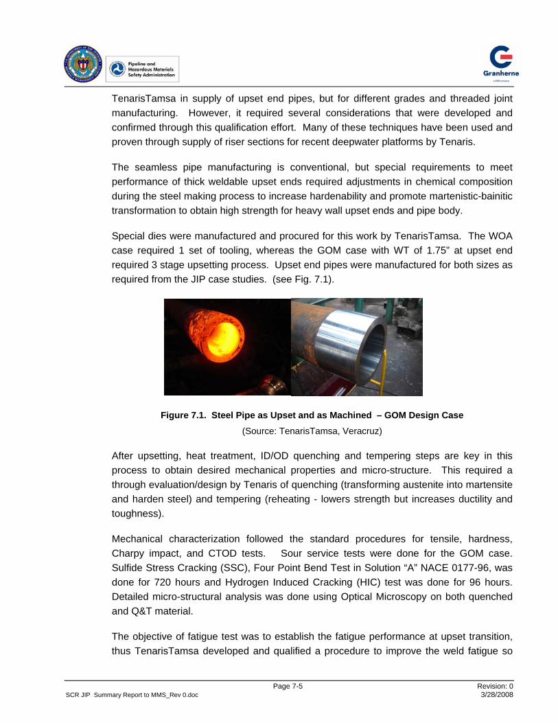
The seamless pipe manufacturing is conventional, but special requirements to meet performance of thick weldable upset ends required adjustme nts in chemical composition during the steel making process to increase hardenability and promote martenistic-bainitic transformation to obtain high strength for heavy wall upset ends and pipe body.
Special dies were manufactured and procured for this work by TenarisTamsa. The WOA case required 1 set of tooling, whereas the GOM ca se with WT of 1.75” at upset end required 3 stage upsetting process. Upset end pipes were manufactured for both sizes as required from the JIP case studies. (see Fig. 7.1).
Figure 7.1. Steel Pipe as Upset and as Machined – GOM Design Case (Source: TenarisTamsa, Veracruz)
After upsetting, heat treatment, ID/OD quenching and tempering steps are key in this process to obtain desired mechanical properties and micro-structure. This required a through evaluation/design by Tenaris of quenching (transforming austenite into martensite and harden steel) and tempering (reheating - lowers strength but increases ductilit y and toughness).
Mechanical characterization followed the standard procedures for tensile, hardness, Charpy impact, and CTOD tests. Sour service tests were done for the GOM case. Sulfide Stress Cracking (SSC), Four Point Bend Test in Solution “A” NACE 0177-96, was done for 720 hours and Hydrogen Induced Cracking (HIC) test was done for 96 hours. Detailed micro-structural analysis was done using Optical Microscopy on both que nched and Q&T material.
The objective of fatigue test was to establish the fatigue performance at upset transition, thus TenarisTamsa developed and qualified a procedure to improve the weld fatigue so
Page 7-5 Revision: 0 SCR JIP Summary Report to MMS_Rev 0.doc 3/28/2008

Figure 7.2. Welding at Upset End c Machines Using Orbital GTAW-P Ar
that fatigue failures in full scale fatigue tests occur at upset transition or in the pipe body (see Fig. 7.2). Welding was done to meet two objectives: to prove weldability of X65 grade riser sections with thick upset ends, and to weld fatigue test samples using conventional offshore/onshore welding approach. This was done for both pipe sizes.
The weldability test required characterization of the HAZ for two cases subject to different combinations of heat input and interpass temperature using an API RP2Z Bevel. All tests passed or exceeded requirements, including hardness HV10 below 248 for sour service case.
(Source: TenarisTamsa, Veracruz)
In case of girth welds for fatigue testing, an additional conside ration was made to develop stronger welds to make sure that during the fatigue tests no failure occurs at weld. TenarisTamsa achieved this by careful selection of welding consumables, and butt welded using GTAW and SAW procedures, with an interpass temperature between 170 deg to 260 deg C. Various mechanical tests (hardness, tensile) and CTOD were performed.
Page 7-6 Revision: 0 SCR JIP Summary Report to MMS_Rev 0.doc 3/28/2008

Full scale fatigue tests were done on a total of nine, 19 ft (5.8 m) long test specimens with upset ends welded at middle for each design case (see Fig. 7.3). The tests were done on resonant bending fatigue machine and mean stress in test sample was introduced through internal pressure.
Figure 7.3. Full Scale Fatigue Testing of Upset SCR TD Z Welded Joints (Source: TenarisTamsa, Veracruz)
The fatigue tests were done at 3 diff erent stress ranges and failures were recorded at 1 million to 17 million cycles and higher cycles in case of run-outs. These tests demonstrated that the fatigue performance at upset end transition is better than the base metal target and runout S-N curves, such as DN V B-1 curve [17], used for presentation of results.
The focus of these tests was on establishing fatigue performance at upset end transition. Thirteen (13) of these tests failed in pipe main body at some distance from upset transition, 3 were run-out, and 2 were with cracks in each in upset length and in weld. The failures were originated both by internal and external surface initiations, which were further studied through fractography.
The JIP Participants visited TenarisTamsa mill and R&D center at Veracruz to review and see various processes used and demonstration of some tests, including full scale fatigue test. From these reviews it became clear that the extensive qualification program undertaken has resulted in bringing both thin and thick wall upset end riser sections in X-65 steel grade, including sour service applications, to project ready stage.
Page 7-7 Revision: 0 SCR JIP Summary Report to MMS_Rev 0.doc 3/28/2008

7.6 Qualification Work with V&M Deutschland, Dusseldorf
VMD manufactured for the JIP work, a total of ten (10) X-65 grade seamless pipes, 10.75 inch (273 mm) in diameter and 40 ft (12.2 m) long, and then prepared samples of riser sections with upset ends by upsetting, testing, and CNC machining. VMD used an existing die from pre vious application, for 10.75 inch OD x 1.033 inch WT (273 mm x 26.25 mm) pipe body and it was upsetted and machined to obtain 1.25 inch (31.75 mm) WT at upset ends. The upset transition design was developed using FEA and consideration of welding and installation of riser sections with upset ends. Discussions were held with major welding and UT contractors, and installation contractors to develop upset end design.
VMD implemented their standard approach for upsetting developed from previous applications for manufacturing and supply of pipes with threaded connectors, and made variations where necessary for weldable upset end solution for the JIP. Various tests listed earlier were performed to ensure required mechanical and corrosion properties are obtained. Fig. 7.4 shows two stages in the upset end manufacturing process: u pset end using a die and design shape obtained after CNC machining.
Figure 7.4. Steel Pipe With Upset End Solution
(Source: V&M Deutschland, Dusseldorf)
The weldability tests were performed per API RP 2Z to establish toughness of the heataffected zone (HAZ). The properties of HAZ depend on heat input during welding and the base material chemical composition. The welding procedure specifications were prepared by Salzgitter Mannesmann Forschung GmbH, Duisburg, Germany (SZMF) for welds produced with low 15.24 to 20.32 kJ/inch (0.6 to 0.8 kJ/mm) and high 63.5 to 76.2 kJ/inch (2.5 to 3.0 kJ/mm) heat input, and welding was performed by various procedures to achieve required welds for weldability and fatigue tests. The welding being performed using mechanized GMAW method is shown in Fig. 7.5.
Page 7-8 Revision: 0 SCR JIP Summary Report to MMS_Rev 0.doc 3/28/2008

Figure 7.5. Welding Using Mechanized GMAW (Source: SZMF, Duisburg)
The weldability tests included CTOD testing of HAZ at its straight fusion line, Charpy transition curves, and tensile tests. The toughness values wer e measured at both fusion line and in the visible HAZ boundary material.
A total of 12 small scale strip fatigue tests and 3 full scale fatigue tests were undert aken with VMD, based on available facilities at R&D center at SZMF, to establish fatigue performance at the upset transition. This approach provides increased number of data points, and the results are normalized to account for effect of undertaking these tests at a different stress ratio (R-ratio) from that used in the tests to develop the base metal S-N curve (such as DNV B-1 S-N curve). The small scale strip fatigue tests have shown fatigue performance of upset end transition beyond the t arget S-N curve for the base metal. With learning from initial small scale tests, full scale fatigue tests using 4-point rotating bending machine were undertaken at SZMF under constant amplitude loads. These tests were planned to continue up to about 2 million cycles.
The JIP Participants and study team visited the VMD Plug Mill at Dusseldorf and SZMF research center in January 2006. The work done by VMD confirmed that it is feasible to manufacture upset end pipes with moderate to high thickness increase at upset end. In the case of X65 riser section with a very thick upset end, multiple passes of upsetting process and additional variation in X-65 chemical composition may be required to obtain higher thickness at upset end with required properties.
Page 7-9 Revision: 0 SCR JIP Summary Report to MMS_Rev 0.doc 3/28/2008

7.7
Page 7-10 Revision: 0 SCR JIP Summary Report to MMS_Rev 0.doc 3/28/2008
Conclusions
The design and qualification work undertaken with TenarisTa msa and VMD confirmed that the it is feasible to manufacture riser sections with upset ends at both ends for pipes with diameter up to 16 inch (406 mm) and the wall thickness could be increased by 50%, depending on pipe diameter and WT. The qualification tasks confirmed feasibility to manufacture riser sections with upset ends by implementation of single stage upsetting process or for thick up sets with multi-stage upsetting process.
The upset end solutio n requires manufacturing and procurement of upsetting dies for specific riser size, thus increasing the delivery time from placement of or der. This solution will thus requ ire early placement of orders as long lead items.

Page 8-1 Revision: 0 SCR JIP Summary Report to MMS_Rev 0.doc 3/28/2008
8.0 INTEGRAL THREADED CONNECTOR SOLUTION
8.1 Approach
The integral threaded connector design developed by V&M Tubes (VAM) for applications in high fatigue zones of riser systems was considered in the JIP for application at SCR TDZ. The integral connector design evaluated in the JIP a ims at providing fatigue performance similar to the base metal through elimination of weld.
The design development, installation, qualification assessment, and qualification program undertaken in the JIP with VAM is discussed in the following sub -sections.
8.2 Design Development
The VAM connector design evaluated in this JIP is manufactured using high grade steel, P110, and has smaller OD compared to weld-on connectors used for high fatigue zones of riser sections. The riser sections are manufactured in 40 ft (12.2 m) length, with integral threaded connectors (pin or box) at each end, for diameters up to 13-5/8 inch (346 mm) by upsetting of pipe ends or by machining a thick walled pipe. It features easy stabbing and quick completion of connection assembly from stabbing to final torque. In case of sour service application, use of C110 grade steel is proposed.
This connector provides significantly higher fatigue performance compared to a conventional SCR welded connection (see Table 4.2). The GOM case study analysis, with the riser sections at TDZ with integral threaded connector over 320 ft (100 m) length, predicted an improvement in the fatigue life estimates at SCR TDZ by a factor of 42 over the estimates for conventional X65 welded riser sections. The significant improvement in fatigue life estimates is due to the combined effect of various design considerations in threading, seals, and managing contact pressure and SCF at critical locations of the threaded joint, and new considerations such as provision of swoosh at pin ends [5, 19]. In addition, the lighter weight high grade steel used for these sections also help.
The connector comprises the following key sub-components or properties/mechanisms that ensure integrity of the system and higher estimate of fatigue life:
• Internal and external shoulder to withstand high bending
• Optimized make-up torque to preload connector to provide high fatigue resistance
• Internal and external metal/metal (M/M) seal to provide highest pressure integrity
• Improved thread profile for high fatigue performance

Page 8-2 Revision: 0 SCR JIP Summary Report to MMS_Rev 0.doc 3/28/2008
8.3 Qualification Status
The integral connector design has evolved over time from OCTG (oil country tubular goods) small diameter production casing applications. VAM Riser integral connector is an improved design with higher fatigue performance, thus it is considered suitable for application at SCR TDZ.
The industry experience with alternative threaded and coupled (T&C) connector design is mostly through applications in top tensioned risers [18]. New designs with higher fatigue resistance from riser sections with T&C connectors have also been developed recently by V&M [19] with some features for fatigue design enhancement features that are similar to those considered in the integral threaded connector design evaluated in this JIP.
There are cases of using weld -on threaded connectors, welded onshore to steel sections, in top tension riser sections with need for higher fatigue performance. But the improvement in the fatigue performance from weld on connectors is similar to that estimated for an onshore weld compared to an offshore weld.
VAM has an ongoing in-house testing program on such connectors with focus on qualifying manufacturing route and performing qualification tests. VAM has undertaken significant tests for their other new riser designs that include some of the features incorporated in the integral connector solution.
Development of installation plans for mechanically connected pipelines and risers has been undergoing in a DeepStar sponsored study [20] and its outcome would provide additional basis and identify need for use of integral connectors qualified in this JIP.
8.4 Qualification Effort
In this JIP, the overall system design issues from use of riser sections with integral connectors were evaluated and focus was kept on the design of connector and cross over segment between P110 and X65 riser sections, and understanding the associated failure modes. The failure modes were identified and detailed analysis and testin g work available with VAM were discussed. The qualification tasks undertaken with VAM, which are specific to this JIP comprises of the following:
• Review of the manufacturing route established, qualit y plan and specification documents, and material test reports
• Participation in the on-going qualification testing program by VAM, which includes make and break tests, sealability test under combined loads, and fatigue tests, through visits to their research and testing laboratories and re views of test reports

• Evaluation of the overall system including assessment of installability from J-lay barge
• Detailed FEA of VAM Riser integral connector for TDZ loads determined from GOM case study for production riser
• Design and detaile d FEA of a cross-over segment between VAM Riser integral connector and X-65 welded riser section for strength, sealability, and SCF estimates
The details of the manufacturing route, quality control plan, and test reports generated in this program were provided by VAM for review and discussion under the JIP qualification task, and to identify if any additional testing work is required. These test repor ts were presented to the JIP Participants for review.
The sealability tests were done for combined loads per ISO 13679 [21] standards and failure tests were performed to check that the connection is better than the pipe. Full scale survival fatigue tests using resonant bending fatigue machine (Fig. 8.1) were completed for a total of 6 samples at Aulnoye-Aymeries R&D center.
The installability of TDZ segments and feasibility of making such connections from J-lay tower were reviewed in detail with major installation contractors and connection tool suppliers, to identify feasible approaches. Thes e reviews confirmed that it is feasible to make offshore connections for SCR TDZ riser sections with threaded ends (pin or ox) at weld stations of some J-lay installation barges, which would be used for installation of rest of SCR sections. However, a tool needs to be developed for rotation of the upper riser section.
Figure 8.1: Fatigue Test of VAM Riser Integral Connector (Source: V&M Tubes, Aulnoye-Aymeries)
Page 8-3 Revision: 0 SCR JIP Summary Report to MMS_Rev 0.doc 3/28/2008

8.5
Page 8-4 Revision: 0 SCR JIP Summary Report to MMS_Rev 0.doc 3/28/2008
The purpose of fatigue test was to evaluate performance of the thread design under cyclic bending loads. These tests have shown that the samples, when tested with light internal pressure to detect leaks, exceed fatigue design and target S-N curves for the base metal (such a s DNV B-1 S-N curve) without any failures. The samples are being subjected to further cycling loads to reach the failure stage (tests ongoing at time of writing of this report).
Detailed FEA of V AM Riser integral connector and cross-over segment were performed for both operating and extreme loads at SCR TDZ, estimated for the GOM case study, to understand the behavior of threaded connections subjected to 100 year and 1,000 year seastates. The analysis results showed adequate strength and low SCF estimates.
The JIP Participants and the study team visited VAM research center for Premium Connections, and its corrosion and metallurgy laboratories, at Aulnoye-Aymeries, France and VAM machining and threading plant at Reisholz, Germany in January and September 2006. They witnessed the fatigue test in progress.
Conclusions
The JIP work for integral connector solution has confirmed its technical feasibility as SCR TDZ design enhancement solution, by its ability to provide a significant increase in the fatigue life estimates. The design and performance of its X-over segment (connection between P110 riser sections with integral connectors and conventional X-65 riser sections) was confirmed through FE analysis. This solution is feasible to manufacture up to 14 inch (356 mm) diameter riser sections. Use of P110 steel grade is qualified for non-sour service applications and the use of C110 grade steel is suggested for sour service applications. Additional qualification effort is required for corrosion-fatigue behavior of high strength steel.
This work has shown that the VAM Riser integral connector has undergone tasks to significantly improve its technology readiness level (TRL) and is available for consideration in FEED stage of projects for site-specific evaluation and development. This alternative has the potential as a high-value design solution for SCR TDZ riser sections and it could provide a significant level of improvement in the fatigue life estimates.

9.0 TITANIUM SEGMENT SOLUTION
9.1 Approach
Titanium segment solution comprises of using riser sections manufactured in titanium at SCR TDZ in place of conventional X-65 riser sections. This solution provides very high increase in fatigue life due to high strength, low elastic modulus, lighter weight, higher fatigue strength (better S-N results) of titanium segment compared to steel (especially in sour service and/or chloride environments), and excellent chemical resistance.
The design development, installation, qualification assessment, and qualification prog ram undertaken in the JIP is discussed in the following sub-sections.
9.2 Design Development
The overall assembly of titanium segment and connections to X-65 conventional SCR sections is illustrated in Figure 9.1.
Figure 9.1. Assembly and Connections of Titanium Sections
The titanium riser sections at TDZ are Ti-Grade 23 or 29 for non-sour service, and Ti-Grade 29 for sour service applications. The GOM case study for sour service case, analyzed with about 320 ft (100 m) length of Grade 29 titanium segment at SCR TDZ, estimated an improvement in the fatigue performance by a factor more than 400 (see Table 4.2), in comparison to the conventional X-65 grade welded riser sections.
Page 9-1 Revision: 0 SCR JIP Summary Report to MMS_Rev 0.doc 3/28/2008

The offshore connections of these tit anium segments would require mechanical connectors similar to those used for a conv entional titanium stress joint (TSJ) at top of the riser. Whereas preassembled titanium-to-steel connections (2 number – 1 at each end ofthe overall titanium segment) can be incorporated offshore via steel-to-steel pipe welds as illustrated in Fig. 9.1. The flange connection using SPO compact flange design [22] is shown in Figure 9.2. This design has been used for both titanium-titanium and steel-titanium connections in case of TSJ’s.
Figure 9.2. SPO Compact Flange (Source: Vector International, Drammen, Norway)
The overall system design of titanium segment at the SCR TDZ, manufacturing methods, and feasible sizes were reviewed, and installability assessment was done to identify specific options. An evaluation of the overall system was done to identify the critical failure modes and specific issues to focus in the JIP.
The details of the SPO compact flange [22] and qualification test reports were obtained from Vector International and were reviewed for SCR TDZ specific issues. Such flanges are already commonly used to connect titanium TSJs to steel riser sections, which are subjected to fatigue, internal pressure, and high tension loads.
The important design consideration of the SPO compact flange is to achieve preloading of bolts and three-part sealing system as follows:
• Inner metal-to-metal seal at the flange heel adjacent to the bore, to ensure no gap between the flanges at the bore during operations and to protect the primary seal.
• Flexible metal ring located in a seal ring groove as the primary seal, which is pressure energized by the deformation of the seal flanges towards seal centerline, and also when subjected to pressure either from inside or outside.
Page 9-2 Revision: 0 SCR JIP Summary Report to MMS_Rev 0.doc 3/28/2008

9.3
Page 9-3 Revision: 0 SCR JIP Summary Report to MMS_Rev 0.doc 3/28/2008
• Outer metal-to-metal seal at the wedge after make-up prevents ingress of materials to flange faces and bolting cavity.
The preloading of bolts and flange face to face contact after makeup enables eliminate the risk of load induced seal damage. The integrity of the primary seal can be determined by the use of a test port to the primary seal groove, which can be pressure tested.
Qualification Status
The qualification status or past experience with key components and operations were identified and some of the companies providing such products were contacted to obtain details from past qualification or development work.
Extensive qualification testing for titanium pipes has been previously undertaken by several companies and manufacturers in Norway and also by RTI Energy Systems [23] for titanium pipes and riser components. Items such as welding, corrosion, fatigue, surface finishes and their effects on S-N curves were examined. RTI Energy Systems undertook additional qualification testing in connection with the preparation of DNV recommended practice for titanium risers [24].
Under the Norwegian DEMO 2000 program, significant qua lification work for material, corrosion, welding, rubber coatin g was undertaken [9, 14]. The heavy-weight coating solution, Vikoweight, by Trelleborg Viking has been qualified for bondability on titanium in the DEMO 2000 project [9]. In case of TDZ enhancement of a production SCR, heavy-weight coating is not required for operating conditions.
Procedures for welding of titanium riser sections offshore, on an installation vessel, have not been qualified, but welding onshore of titanium riser sections has been qualified through the DEMO 2000 project.
Significant FEA of SPO Compact Flange connections have been done by both Vector International and RTIES for designs applied in various riser TSJ ’s to confirm strength and fatigue integrity of this mechanical connection.
9.4 Qualification Tasks
The important areas requiring detailed assessment in the JIP were identified as follows:
• Connection of titanium-to-titanium and titanium-to-steel riser sections
• Electrical Isolation requirements between steel and titanium riser sections for certain conditions

Page 9-4 Revision: 0 SCR JIP Summary Report to MMS_Rev 0.doc 3/28/2008
• Required surface finish for good coating adhesion, to prevent premature crack initiation in Titanium and to detect flaws by ultrasonic testing (UT)
FEA of titanium-to-steel SPO compact flange connection at the ends of titanium segment was done by Vector International for this JIP. The focus of this analysis was to evaluate its performance when subjected to the loading conditions at SCR TDZ, through pe rforming functionality and SCF analysis, and addressing the bolt fatigue by developing a transfer function between nominal pip e stress range and bolt stress range. The analysis provedthat the titanium-to-steel connection would meet the performance requirements in its application at SCR TDZ.
Through the assessment work done in the JIP, it was identified that for most applications, the currently available non-isolating designs would be adequate. But for dynamic application cases with hot sour flows with high water cut, a new design of an isolation system between steel and titanium riser sections would be required.
The feasibility of an alternative syntactic polypropylene coating system over titanium as insulation and coating functions was proposed by Socotherm and evaluated in this JIP. The key issue identified for this c ase is the ability to achieve desired titanium OD surface anchor profile and coating bond strength using Wheelabrator grit blasting. The qualification testing work undertaken in this JIP for this issue included the following:
• Titanium segment surface preparation and coating integrity testing by Socotherm, Buenos Aires
• Laboratory metallurgical examination and hot seawater corrosion testing of grit blasted titanium samples at RTI, Niles, Ohio
• S-N fatigue tests on grit blasted Grade 29 titanium pipe strip specimens at EWI, Columbus, Ohio.
The above tests proved that the grit blasting applied to titanium pipe OD surface by Socotherm does not deteriorate fatigue life while safely meeting established fatigue design curve; nor does it compromise titanium se awater corrosion resistance.
Conclusions
The work undertaken in this JIP has shown a practical approach for application of titaniu m segment at TDZ, and its connection with conventional X-65 riser sections. Titanium segment solution can be manufactured up to 36 inch (914 mm) diameter by extrusion process. For sour-service applications, Grade 29 titanium sections shall be used, and for non sour-service applications Grade 23 or 29 titanium sections be used. However for higher temperature service above 75oC, Grade 29 titanium sections must be used.
9.5
Page 9-5 Revision: 0 SCR JIP Summary Report to MMS_Rev 0.doc 3/28/2008
The qualification assessment confirmed that titanium component performance has beenproven from previous work done in various programs/projects and standards development. The qualification work undertaken in the JIP to address the important conditions at SCR TDZ confirmed feasibility of steel-to-titanium connection and alternate surface finish.

Page 10-1 Revision: 0 SCR JIP Summary Report to MMS_Rev 0.doc 3/28/2008
10.0 SUMMARY AND CONCLUSIONS
The SCR TDZ JIP initiative has been successful in increasing the technology readiness
level (TRL) of 4 alternative design solutions undertaken to solve the industry concern with
SCR fatigue performance at touch down zone (TDZ), when used with floating production
units in deepwater and ultra-deepwater. This issue becomes more severe in case of SCR
applications with high motion floating units, larger diameter export risers, and production
risers with sour service and HPHT fluids, and for applications in fields with lesser water
depths or firmer seabed.
The JIP work has lead to the development and qualification, or increase in TRL, of
multiple “design solutions” selected with the potential to significantly increase the fatigue
performance at TDZ. These solutions are grouped as below:
� X-65 Grade solutions :
– Thick light weight coating
– Riser sections with thick upset ends
� High Strength solutions:
– Riser sections with Integral threaded connector
– Titanium segment with flange connection to X65 riser sections
The X-65 grade solutions are “welded solutions,” and the case studies showed that in
some applications these solutions could provide an increase in the fatigue life estimates
by a factor of 10. Whereas, the high strength solutions replace X-65 grade riser sections
with welds by high strength riser sections with threaded or flange connections, or by
titanium welds (onshore) with high fatigue performance (better S-N results). The case
studies showed that the high strength solutions could provide significantly higher fatigue
performance (beyond factor of 10 increase) at the SCR TDZ. Thus, these four design
solutions have potential to provide a significant change from other approaches considered
by the industry to remedy low fatigue life estimates at SCR TDZ. The application of high-
strength solutions could also be extended above TDZ to provide a “strength + fatigue”
solution and enable further increase in selection of SCR design in projects.

Page 10-2 Revision: 0 SCR JIP Summary Report to MMS_Rev 0.doc 3/28/2008
The selected products or their variations have been used previously by the offshore oil &
gas industry or else their variations have been qualified for less demanding applications.
Thus in general, the manufacturing facilities, installation equipment, and qualified
techniques are available for these solutions.
In general, the above solutions would apply to both sour and non-sour service
applications, with feasible riser sizes (D, t) defined by manufacturing or application (e.g.,
coating) limits per the facilities of product manufacturers. Thick light weight coating (LWC)
can be applied on all pipe sizes, thus it provides the only cost-effective solution for large
diameter export risers compared to other solutions developed in the JIP. The feasibility of
manufacturing riser sections with thick ends by upsetting process is identified to be up to
16” OD and the limiting wall thickness at upset end is defined by the weldability offshore,
which may vary with installation contractors. The riser sectio ns with integral connectors
are fe sible to manufacture u a p to 14” OD riser pipes, whereas titanium riser sections
could be manufactured up to 36” OD.
The install tion of SCR TDZ sections with these s a olutions will be feasible by conventional
J-lay installation, a more common approach used for deepwater SCRs. There may be
potent al for reeling+J-lay installa i tion for certain sizes.
Being “design solutions” they would enable development of an optimum SCR TDZ design,
or an inte rated FPS hull and riser design for site-specific requirement g s with minimal
impact on the overall SCR cost and schedule. These solutions provide high value in
terms of improved reliability of SCR and have potential to provide increases savings in the
overall platform design and benefits to the riser integrity program.
The case studies undertaken in this JIP were for the Gulf of Mexico and West of Africa
regions, but the applications at TDZ of solutions developed will be similar in other regions.
In some regions, such as the North Sea the riser length at TDZ requiring design
enhancement by these solutions would be longer compared to those estimated from the
JIP case studies. The improvement in fatigue life and the associated cost to implement
these solutions will vary for different solutions and depend on a number of field specific
parameters identified earlier.
Page 10-3 Revision: 0 SCR JIP Summary Report to MMS_Rev 0.doc 3/28/2008
An optimum solution for a specific field development scenario would vary, thus multiple
TDZ designs (4 solutions with 5 product manufacturers) developed in this JIP would
provide feasible alternatives for a broader range of applications in most regions
worldwide. These solutions could also find applications in ongoing projects, where
significant changes from the original design basis calls for measures to consider changes
in design at SCR TDZ.
The qualification work undertaken within this JIP included design, analysis, manufacturing
(or application) and testing, and also dealt with construction, transportation, installation,
and in-service performance issues, which all have helped in providing clarity for their
potential applications in projects. With significant development effort undertaken in this
JIP, progress has been made to significantly improve their TRL status and increase the
probability of their consideration/use in projects for site-specific applications at the SCR
TDZ in all regions.
The qualification requirements could vary among various operating companies, in line with
variations in their new technology/concept selection procedures. The qualification work
performed in this JIP is significant and in most cases enables them to be classified as
project ready solution by companies. However, some op erating companies based on their
internal evaluation procedures may consider need for additional testing or analysis.

Page 11-1 Revision: 0 SCR JIP Summary Report to MMS_Rev 0.doc 3/28/2008
11.0 REFERENCES
[ 1 ] Aggarwal, R., Mourelle, M.M., Kristoffersen, S, Godinot, H., Vargas, P., Else, M., Schutz, R.W., Portesan, G., Izquierdo, A., Quintanilla, H., Schamuhn, S., and Sches, C., 2007, “Development and Qualification of Alternative Solutions for Improved Fatigue Performance of Deepwater Steel Catenary Risers,” Proc. 26th International Conference on Offshore Mechanics and Arctic Engineering, OMAE 2007, Paper No. 29325, San Diego, June 10-15, 2007.
[ 2 ] Aggarwal, R., Meling, T., Bhat, S., van der Linden, C., Mourelle, M., and Else, M., 2006, “Qualification of Enhanced SCR Design Solutions for Improving Fatigue Life at Touch Down Zone,” Proc. 16th International Offshore and Polar Engineering Conference, ISOPE 2006, Paper No. EF 03, San Francisco, May 28 - June 2 , 2006.
[ 3 ] Aggarwal, R., Bhat, S., Meling, T., Mourelle, M., Linden, C., and Else, M., 2005, “Qualification of S olutions to Improve Fatigue Life at SCR Touch Down Zone,” Proc. 17th Deep Offshore Technology Conference, DOT 2005, Vitoria, Espirito Santo, November 8-10, 2005.
[ 4 ] Aggarwal, R., Izquierdo, A., Quintanilla, H., Schamuhn, S., Portesan, G., Mockel, M., Vargas, P., Kristoffersen, S, Mourelle, M.M., Godinot, H., Lespinasse, P., Else, M., 2007, “Qualification of Alternate Solutions with Seamless, Weldable X-65 Grade Riser Sections to Improve Fatigue Performance of Deepwater Steel Catenary Ris ers,” Presented at DOT 2007, Stavanger, October 10-12, 2007.
[ 5 ] Aggarwal, R., Baxter, C., Schutz, R.W., Sches, C., Massaglia, J., Kristoffersen, S, Vargas, P., Mourelle, M.M., Godinot, H., Else, M., 2008, “Qualification of High Strength Solutions to Improve Fatigue Performance of Deepwater Steel Catenary Risers,” to be presented at DOT 2008, Houston, February 12-14, 2008.
[ 6 ] Izquierdo, A., Quintanilla, H., Aggarwal, R., Garcia, E., Lopez, V., Richard, G., Marquee, E., Dell Erba, D., Di Vito, L., 2008, “Qualification of Weldable X65 Steel Riser Sections with Upset Ends to Improve Fatigue Performance of Deepwater Steel Catenary Risers,” to be presented at 18th International Offshore and Polar Engineering Conference, ISOPE 2008, Vancouver, July 7-11, 2008.
[ 7 ] Kopp, F., Perkins, G., Prentice, G., and Stevens, D., 2003, “Production and Inspection Issues for Steel Catenary Riser Welds,” Proc. 35th Offshore Technology Conference, Paper No. OTC 15144, Houston, May 5-8, 2003.

Page 11-2 Revision: 0 SCR JIP Summary Report to MMS_Rev 0.doc 3/28/2008
[ 8 ] Van der Ent, J., van Nisselroij, J., Kopp, F., Otter, A., Heli, N., and Judd, S., 2006, “Automatic Ultrasonic Inspection of SCRs with a Corrosion Resistant Alloy Layer,” Proc. 38th Offshore Technology Conference, Paper No. OTC 17898, Houston, May 1-4, 2006.
[ 9 ] Hauge, M., 2003, “Titanium Gas Export Risers from Semi Submersible Platforms in Harsh Environment, 2003, “Proc. 15th Deep Offshore Technology Conference, DOT 2003, Marseille, France, November 19-21, 2003.
[ 10 ] Slagsvold, L, Hande, O., Jahr, D.M., 2002, “Catenary Composite Riser,” Proc. 14th
Deep Offshore Technology Conference, DOT 2002, New Orleans, November 13-15, 2002.
[ 11 ] Torres, A.L.F.L., Gonzalez, E.C., Mourelle, M.M., Siqueira, M.Q., Dantas, C.M.S., Silva, R.M.C., 2002, “Lazy-wave Steel Rigid Risers for Turret-Moored FPSO.” Proc. 21st International Conference on Offshore Mechanics and Arctic Engineering, Paper OMAE 2002-28124, Oslo, June 23-28, 2002.
[ 12 ] Torres, A.L.F.L., Gonzalez, E.C., Ferreira, M.D.A., Siqueira, M.Q., Mourelle, M.M., and Silva, R.M.C., 2003, “Lazy-Wave Steel Rigid Risers for FSO with Spread Mooring Anchoring System,” Proc. 22nd International Conference on Offshore Mechanics and Arctic Engineering, OMAE 2003-37068, Cancun, June 8-13, 2003.
[ 13 ] Garrett, D.L., Chappell, J.F., Petruska, D.J., and Cook, H.H., 2002, “Steel Lazy Wave Risers on a Turret-Moored FSO,” Proc. 14th Deep Offshore Technology Conference, DOT 2002, New Orleans, November 13-15, 2002.
[ 14 ] Karunakaran, D., Meling, T.S., Kristoffersen, S., and Lund, K.M., 2005, “Weight-optimized SCRs for Deepwater Harsh Environment,” Proc. 37th Offshore Technology Conference, Paper No. OTC 17224, Houston, May 2-5, 2005.
[ 15 ] Det Norske Veritas, 2002, “Qualification Procedures for New Technology,” DNV-RP-A203, Hovik.
[ 16 ] Karunakaran, D., Dutta, A., Clausen, T., and Lund, K.M. (2002). “Steel Catenary Riser Configurations for Large Motion Semi Submersibles with Light weight Coating,” Deep Offshore Technology Conference, DOT, New Orleans.
[ 17 ] Det Norske Veritas, 2005, “Fatigue Design of Offshore Steel Structures,” DNV-RP-C203, Hovik.

Page 11-3 Revision: 0 SCR JIP Summary Report to MMS_Rev 0.doc 3/28/2008
[ 18 ] Cromb, J., Delepine, Y., Bedore T., Bradley, B., Roussie, G., and Massaglia, J., 2006, “Development and Installation of a New Generation Outer Riser System on Anadarko’s Constitution SPAR,” Proc. 18th Deep Offshore Technology Conference, DOT 2006, Houston, November 28-30, 2006.
[ 19 ]
erence on Offshore mechanics and Arctic Engineering, OMAE 2007, Paper No. 29263, San Diego, June 10-15, 2007.
Sches, C., Hill, J.W., Peter, T., Massaglia, J., and Lepine, E., 2007, “Fatigue Resistant Threaded and Coupled Connectors: the New Standard for Deep Water Riser Applications,” Proc. 26th International Conf
[ 20 ] nical Connectors,” Proc. 18th Deep Offshore Technology Conference, DOT
2006, Houston, November 28-30, 2006.
Pollack, J., Riggs, D.C., and Guo, F., 2006, “SCR Self-installation from an FPU using Mecha
[ 21 ] ISO 13679:2002, “Petroleum and Natural Gas Industries – Procedures for Testing Casing and Tubing Connections,” Developed by ISO/TC 67/SC 5/WG 2a, December 13, 2002.
[ 22 ] Lassesen, S., Eriksen, T., Teller, F., 2002, “NORSOK L-005; Compact Flanged Connections (CFC) – The New Flange Standard,” Proc. of the ASME Pressure Vessels and Piping Conference, ASME-PVP 2002, August 4-8, 2002, Vancouver.
[ 23 ] Baxter, C.F., Schutz, R.W., and Caldwell, C.S., 2007, “Experience & Guidance in the Use of Titanium Components in Steel Catenary Riser Systems,” Proc. 39th Offshore Technology Conference, Paper No. OTC 18624, Houston, April 28-May 3, 2007.
[ 24 ] Det Norske Veritas, 2002, “Recommended Practice Design of Titanium Risers,” DNV-RP-F201, Hovik.