Embed Size (px)
Citation preview
Project Number: Tracking Code: TC0634--1150
Requested by: Brandon Harpenau Date: 8/25/2006 Product Rev: 0
Part #: SCP2-10-10-S-2.00-S Lot #: 0 Tech: Tony Wagoner Eng: Troy Cook
Part description: SCR2/SCP2 Size 10 Qty to test: 50
Test Start: 10/21/2006 Test Completed: 1/3/2007
Page 1 of 23
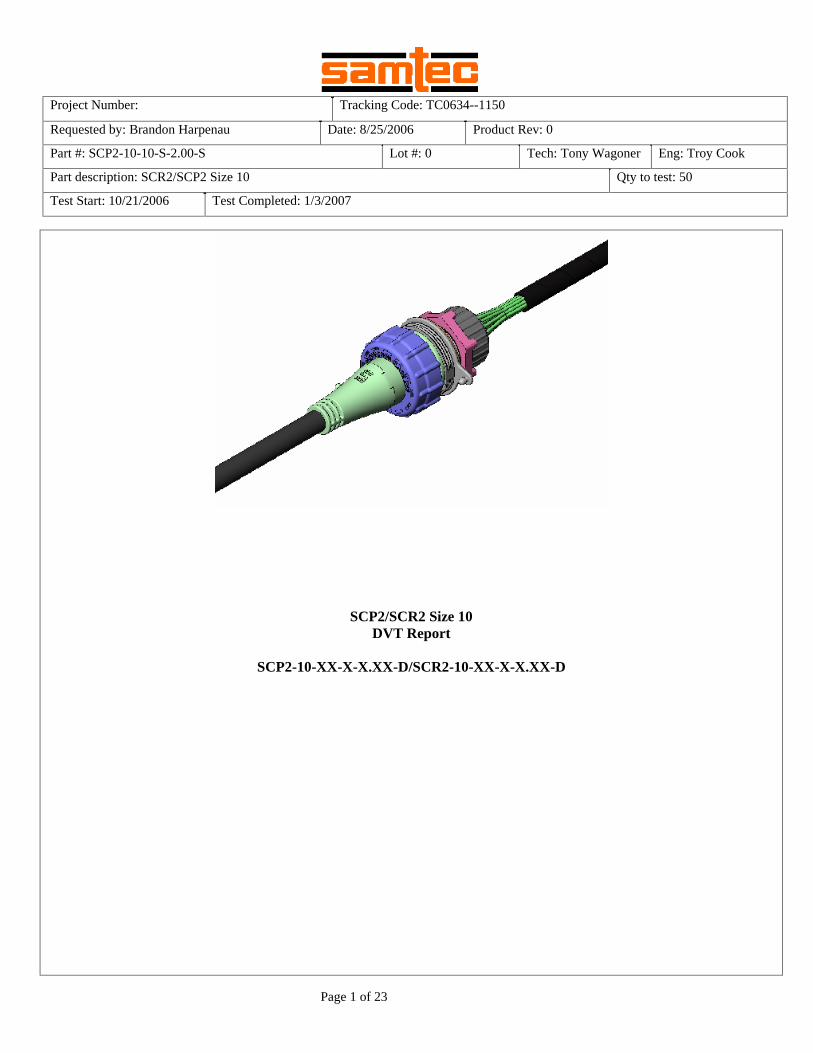
SCP2/SCR2 Size 10 DVT Report
SCP2-10-XX-X-X.XX-D/SCR2-10-XX-X-X.XX-D
Tracking Code: TC0634--1150 Part #: SCP2-10-10-S-2.00-S Part description: SCR2/SCP2 Size 10
Page 2 of 23
CERTIFICATION
All instruments and measuring equipment were calibrated to National Institute for Standards and Technology (NIST) traceable standards according to IS0 10012-l and ANSI/NCSL 2540-1, as applicable. All contents contained herein are the property of Samtec. No portion of this report, in part or in full shall be reproduced without prior written approval of Samtec. SCOPE To perform the following tests: Full DVT. Flow chart is attached. APPLICABLE DOCUMENTS Standards: EIA Publication 364 TEST SAMPLES AND PREPARATION
1) All materials were manufactured in accordance with the applicable product specification. 2) All test samples were identified and encoded to maintain traceability throughout the test sequences. 3) After soldering, the parts to be used for LLCR and DWV/IR testing were cleaned according to TLWI-0001. 4) Either an automated cleaning procedure or an ultrasonic cleaning procedure may be used. 5) The automated procedure is used with aqueous compatible soldering materials. 6) Parts not intended for testing LLCR and DWV/IR are visually inspected and cleaned if necessary. 7) Any additional preparation will be noted in the individual test sequences. 8) Solder Information: None Used 9) Re-Flow Time/Temp: See accompanying profile. 10) Internal Test PCBs used: None Used

Tracking Code: TC0634--1150 Part #: SCP2-10-10-S-2.00-S Part description: SCR2/SCP2 Size 10
Page 3 of 23
OVEN PROFILE (Soldering Parts to Test Boards) – NO TEST BOARDS USED
Tracking Code: TC0634--1150 Part #: SCP2-10-10-S-2.00-S Part description: SCR2/SCP2 Size 10
Page 4 of 23
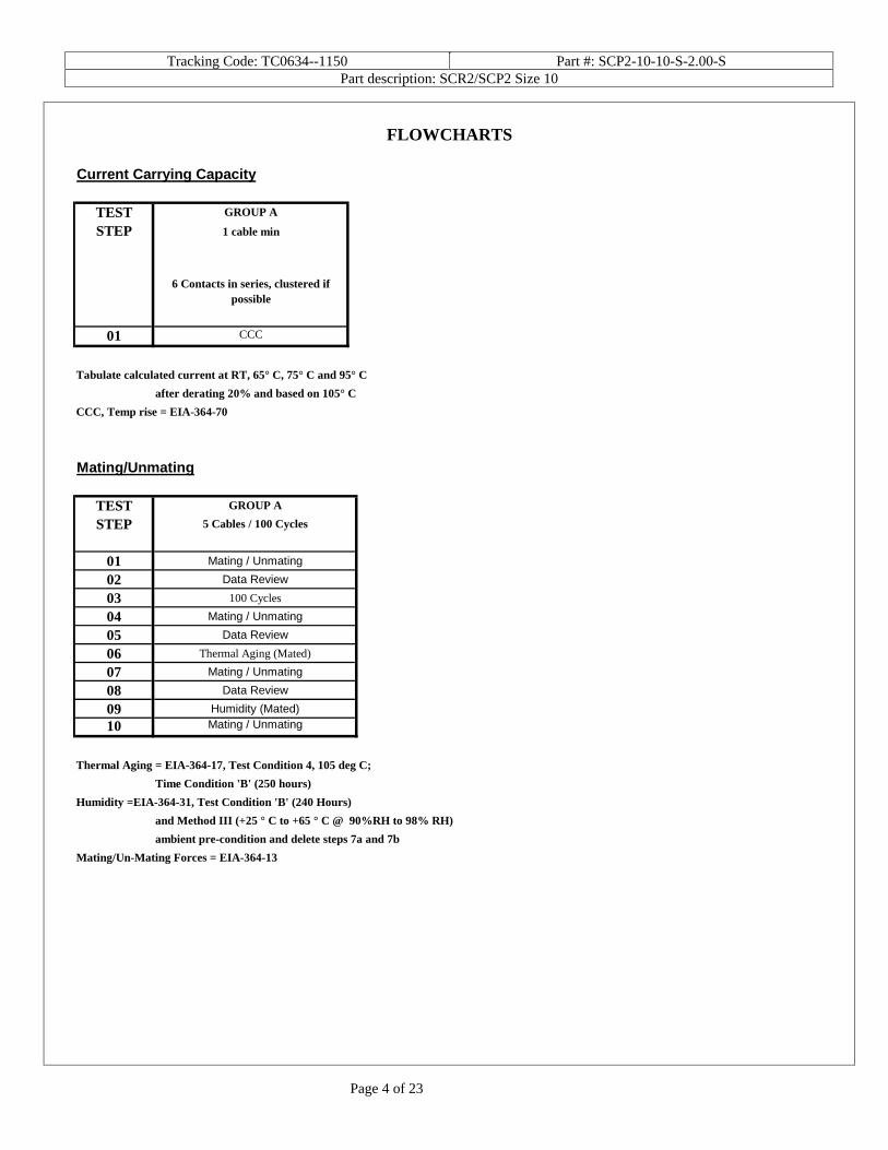
FLOWCHARTS
Current Carrying Capacity
TEST GROUP A
STEP 1 cable min
6 Contacts in series, clustered if possible
01 CCC
Tabulate calculated current at RT, 65° C, 75° C and 95° C
after derating 20% and based on 105° C
CCC, Temp rise = EIA-364-70 Mating/Unmating
TEST GROUP A
STEP 5 Cables / 100 Cycles
01 Mating / Unmating
02 Data Review
03 100 Cycles
04 Mating / Unmating
05 Data Review
06 Thermal Aging (Mated)
07 Mating / Unmating
08 Data Review
09 Humidity (Mated)
10 Mating / Unmating
Thermal Aging = EIA-364-17, Test Condition 4, 105 deg C;
Time Condition 'B' (250 hours)
Humidity =EIA-364-31, Test Condition 'B' (240 Hours)
and Method III (+25 ° C to +65 ° C @ 90%RH to 98% RH)
ambient pre-condition and delete steps 7a and 7b
Mating/Un-Mating Forces = EIA-364-13

Tracking Code: TC0634--1150 Part #: SCP2-10-10-S-2.00-S Part description: SCR2/SCP2 Size 10
Page 5 of 23
FLOWCHARTS Continued
Water & Dust - DC-01 Dust Cover
3 Connectors 3 ConnectorsTEST GROUP A GROUP A1
STEP SCP1-17-16-T-2.00-D / DC-01 Dust Cover SCP1-17-16-T-2.00-D / DC-01 Dust Cover
01 Visual Visual
02 Dust Test Water Test
03 Visual Visual
Dust/Water Testing = Per CEI/IEC 60529 Code IP67 Water & Dust - DC-02 Dust Cover
3 Connectors 3 ConnectorsTEST GROUP A GROUP A1
STEP SCP1-17-16-T-2.00-D / DC-02 Dust Cover SCP1-17-16-T-2.00-D / DC-02 Dust Cover
01 Visual Visual
02 Dust Test Water Test
03 Visual Visual
Dust/Water Testing = Per CEI/IEC 60529 Code IP67 IR / DWV
TEST GROUP A GROUP B GROUP C
STEP 2 Boards 2 Boards 2 Boards
Ambient Thermal Humidity
01 IRDWV Initial Thermal Humidity
02 IR/DWV after Thermal IR/DWV after Humidity
Thermal Aging = EIA-364-17, Test Condition 1, Except 60 deg C;
Time Condition 'A' (96 hours)
Humidity =EIA-364-31, Test Condition 'A' (96 Hours)
and Method III (+25 ° C to +65 ° C @ 90%RH to 98% RH)
ambient pre-condition and delete steps 7a and 7b
IR = EIA-364-21
DWV = EIA-364-20
Tracking Code: TC0634--1150 Part #: SCP2-10-10-S-2.00-S Part description: SCR2/SCP2 Size 10
Page 6 of 23
FLOWCHARTS Continued
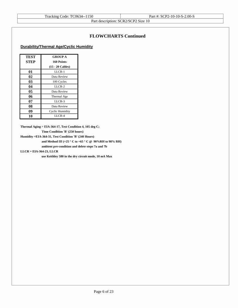
Durability/Thermal Age/Cyclic Humidity
TEST GROUP A
STEP 160 Points
(15 - 20 Cables)
01 LLCR-1
02 Data Review
03 100 Cycles
04 LLCR-2
05 Data Review
06 Thermal Age
07 LLCR-3
08 Data Review
09 Cyclic Humidity
10 LLCR-4
Thermal Aging = EIA-364-17, Test Condition 4, 105 deg C;
Time Condition 'B' (250 hours)
Humidity =EIA-364-31, Test Condition 'B' (240 Hours)
and Method III (+25 ° C to +65 ° C @ 90%RH to 98% RH)
ambient pre-condition and delete steps 7a and 7b
LLCR = EIA-364-23, LLCR
use Keithley 580 in the dry circuit mode, 10 mA Max

Tracking Code: TC0634--1150 Part #: SCP2-10-10-S-2.00-S Part description: SCR2/SCP2 Size 10
Page 7 of 23
ATTRIBUTE DEFINITIONS
The following is a brief, simplified description of attributes. THERMAL:
1) EIA-364-17, Temperature Life with or without Electrical Load Test Procedure for Electrical Connectors. 2) Test Condition 4 at 105° C. 3) Test Time Condition B for 250 hours. 4) Connectors are sometimes mated and all samples are pre-conditioned at ambient.
HUMIDITY:
1) Reference document: EIA-364-31, Humidity Test Procedure for Electrical Connectors. 2) Test Condition B, 240 Hours. 3) Method III, +25° C to + 65° C, 90% to 98% Relative Humidity excluding sub-cycles 7a and 7b. 4) Connectors are sometimes mated and all samples are pre-conditioned at ambient.
TEMPERATURE RISE (Current Carrying Capacity, CCC):
1) EIA-364-70, Temperature Rise versus Current Test Procedure for Electrical Connectors and Sockets.
2) When current passes through a contact, the temperature of the contact increases as a result of I2R (resistive)
heating. 3) The number of contacts being investigated plays a significant part in power dissipation and therefore
temperature rise. 4) The size of the temperature probe can affect the measured temperature. 5) Copper traces on PC boards will contribute to temperature rise:
a. Self heating (resistive) b. Reduction in heat sink capacity affecting the heated contacts
6) A de-rating curve, usually 20%, is calculated. 7) Calculated de-rated currents at three temperature points are reported:
a. Ambient
b. 65? C
c. 75? C
d. 95? C
8) Typically, neighboring contacts (in close proximity to maximize heat build up) are energized. 9) The thermocouple (or temperature measuring probe) will be positioned at a location to sense the maximum
temperature in the vicinity of the heat generation area. 10) A computer program, TR 803.exe, ensures accurate stability for data acquisition. 11) Hook-up wire cross section is larger than the cross section of any connector leads/PC board traces, jumpers,
etc. 12) Hook-up wire length is longer than the minimum specified in the referencing standard.
MATING/UNMATING:
1) Reference document: EIA-364-13, Mating and Unmating Forces Test Procedure for Electrical Connectors. 2) The full insertion position was to within 0.003” to 0.004” of the plug bottoming out in the receptacle to
prevent damage to the system under test. 3) One of the mating parts is secured to a floating X-Y table to prevent damage during cycling.
Tracking Code: TC0634--1150 Part #: SCP2-10-10-S-2.00-S Part description: SCR2/SCP2 Size 10
Page 8 of 23
INSULATION RESISTANCE (IR):
To determine the resistance of insulation materials to leakage of current through or on the surface of these materials when a DC potential is applied.
1) PROCEDURE: a. Reference document: EIA-364-21, Insulation Resistance Test Procedure for Electrical Connectors. b. Test Conditions:
i. Between Adjacent Contacts ii. Electrification Time 2.0 minutes iii. Test Voltage (500 VDC) corresponds to calibration settings for measuring resistances.
2) MEASUREMENTS: 3) When the specified test voltage is applied (VDC), the insulation resistance shall not be less than 5000
megohms. DIELECTRIC WITHSTANDING VOLTAGE (DWV):
To determine if the sockets can operate at its rated voltage and withstand momentary over potentials due to switching, surges, and other similar phenomenon. Separate samples are used to evaluate the effect of environmental stresses so not to influence the readings from arcing that occurs during the measurement process.
1) PROCEDURE: a. Reference document: EIA-364-20, Withstanding Voltage Test Procedure for Electrical Connectors. b. Test Conditions:
i. Between Adjacent Contacts ii. Rate of Application 500 V/Sec
iii. Test Voltage (VAC) until breakdown occurs 2) MEASUREMENTS/CALCULATIONS
a. The breakdown voltage shall be measured and recorded. b. The dielectric withstanding voltage shall be recorded as 75% of the minimum breakdown voltage. c. The working voltage shall be recorded as one-third (1/3) of the dielectric withstanding voltage (one-
fourth of the breakdown voltage). DURABILITY/LLCR:
1) EIA-364-23, Low Level Contact Resistance Test Procedure for Electrical Connectors and Sockets. 2) A computer program, LLCR 221.exe, ensures repeatability for data acquisition. 3) The following guidelines are used to categorize the changes in LLCR as a result from stressing
a. <= +5.0 mOhms:----------------------------Stable b. +5.1 to +10.0 mOhms: ---------------------Minor c. +10.1 to +15.0 mOhms:--------------------Acceptable d. +15.1 to +50.0 mOhms:--------------------Marginal e. +50.1 to +2000 mOhms: -------------------Unstable f. >+2000 mOhms: ----------------------------Open Failure
Tracking Code: TC0634--1150 Part #: SCP2-10-10-S-2.00-S Part description: SCR2/SCP2 Size 10
Page 9 of 23
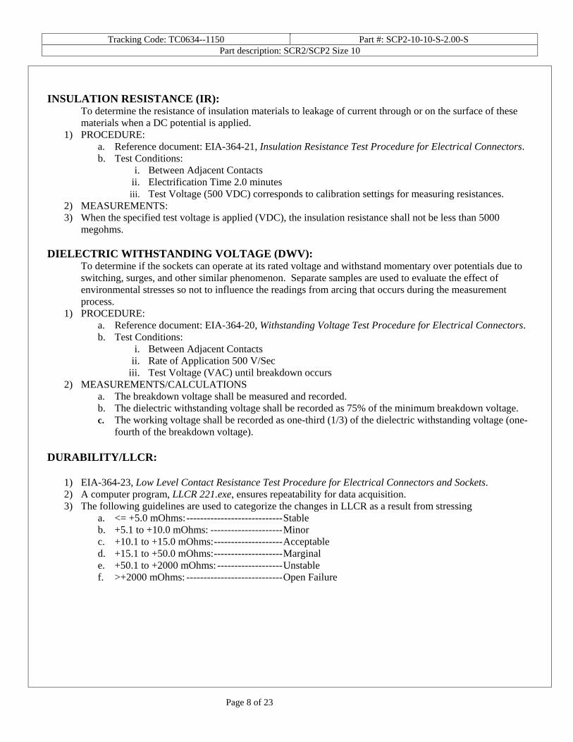
SUPPLEMENTAL TESTS WATER TESTING
1) Reference document: CEI/IEC 60529 Code IP67 2) Torque Requirements for Testing:
A. Connector Torque: 5.0 - 10.0 In.-Lb. B. Panel Mount Torque: 5.0 - 10.0 In.-Lb. C. Dust Cover Torque: 5.0 - 10.0 In.-Lb D. Machine Screw Torque to Fixture: 10.0 In.-Lb. Min.
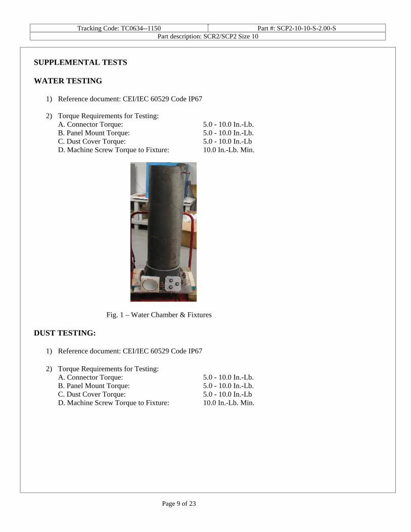
Fig. 1 – Water Chamber & Fixtures DUST TESTING:
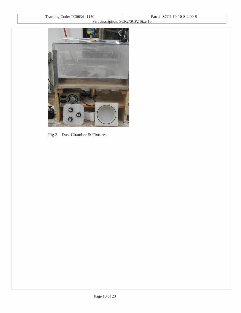
1) Reference document: CEI/IEC 60529 Code IP67
2) Torque Requirements for Testing: A. Connector Torque: 5.0 - 10.0 In.-Lb. B. Panel Mount Torque: 5.0 - 10.0 In.-Lb. C. Dust Cover Torque: 5.0 - 10.0 In.-Lb D. Machine Screw Torque to Fixture: 10.0 In.-Lb. Min.
Tracking Code: TC0634--1150 Part #: SCP2-10-10-S-2.00-S Part description: SCR2/SCP2 Size 10
Page 10 of 23
Fig.2 – Dust Chamber & Fixtures

Tracking Code: TC0634--1150 Part #: SCP2-10-10-S-2.00-S Part description: SCR2/SCP2 Size 10
Page 11 of 23
RESULTS
Temperature Rise, CCC at a 20% de-rating
• CCC for a 30°C Temperature Rise----------------------- 2.9 A per contact with 6 adjacent contacts powered Mating – Unmating Forces
• Initial o Mating
Min --------------------------------------- 2.9 Lb. Max -------------------------------------- 5.0 Lb.
o Unmating Min --------------------------------------- 2.6 Lb. Max -------------------------------------- 4.8 Lb.
• After 100 Cycles o Mating
Min --------------------------------------- 4.1 Lb. Max -------------------------------------- 6.9 Lb.
o Unmating Min --------------------------------------- 4.1 Lb. Max -------------------------------------- 6.4 Lb.
• After Thermals o Mating
Min --------------------------------------- 2.9 Lb. Max -------------------------------------- 4.5 Lb.
o Unmating Min --------------------------------------- 2.8 Lb. Max -------------------------------------- 4.6 Lb.
• After Humidity o Mating
Min --------------------------------------- 2.7 Lb. Max -------------------------------------- 3.5 Lb.
o Unmating Min --------------------------------------- 3.1 Lb. Max -------------------------------------- 3.8 Lb.
Water & Dust Testing – Connector to Connector Initial (Before Exposure) After Exposure
Water No Water Present No Water Present Dust No Water Present No Water Present
Water & Dust Testing – Connector to DC-01 Dust Cover Initial (Before Exposure) After Exposure
Water No Water Present No Water Present Dust No Water Present No Water Present
Tracking Code: TC0634--1150 Part #: SCP2-10-10-S-2.00-S Part description: SCR2/SCP2 Size 10
Page 12 of 23
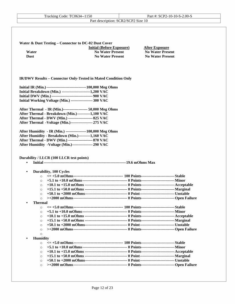
Water & Dust Testing – Connector to DC-02 Dust Cover Initial (Before Exposure) After Exposure
Water No Water Present No Water Present Dust No Water Present No Water Present
IR/DWV Results – Connector Only-Tested in Mated Condition Only Initial IR (Min.) -------------------------------100,000 Meg Ohms Initial Breakdown (Min.) ----------------------1,200 VAC Initial DWV (Min.) -------------------------------- 900 VAC Initial Working Voltage (Min.) ----------------- 300 VAC After Thermal - IR (Min.)------------------- 50,000 Meg Ohms After Thermal - Breakdown (Min.)----------1,100 VAC After Thermal - DWV (Min.) ------------------- 825 VAC After Thermal -Voltage (Min.)----------------- 275 VAC After Humidity - IR (Min.) ----------------100,000 Meg Ohms After Humidity - Breakdown (Min.)---------1,160 VAC After Thermal - DWV (Min.) ------------------- 870 VAC After Humidity -Voltage (Min.)---------------- 290 VAC Durability / LLCR (100 LLCR test points)
• Initial ----------------------------------------------------------------19.6 mOhms Max
• Durability, 100 Cycles o <= +5.0 mOhms----------------------------------- 100 Points--------------------------Stable o +5.1 to +10.0 mOhms----------------------------------- 0 Points--------------------------Minor o +10.1 to +15.0 mOhms --------------------------------- 0 Points--------------------------Acceptable o +15.1 to +50.0 mOhms --------------------------------- 0 Points--------------------------Marginal o +50.1 to +2000 mOhms--------------------------------- 0 Point---------------------------Unstable o >+2000 mOhms------------------------------------------ 0 Points--------------------------Open Failure
• Thermal o <= +5.0 mOhms----------------------------------- 100 Points--------------------------Stable o +5.1 to +10.0 mOhms----------------------------------- 0 Points--------------------------Minor o +10.1 to +15.0 mOhms --------------------------------- 0 Points--------------------------Acceptable o +15.1 to +50.0 mOhms --------------------------------- 0 Points--------------------------Marginal o +50.1 to +2000 mOhms--------------------------------- 0 Point---------------------------Unstable o >+2000 mOhms------------------------------------------ 0 Points--------------------------Open Failure o
• Humidity o <= +5.0 mOhms----------------------------------- 100 Points--------------------------Stable o +5.1 to +10.0 mOhms----------------------------------- 0 Points--------------------------Minor o +10.1 to +15.0 mOhms --------------------------------- 0 Points--------------------------Acceptable o +15.1 to +50.0 mOhms --------------------------------- 0 Point---------------------------Marginal o +50.1 to +2000 mOhms--------------------------------- 0 Point---------------------------Unstable o >+2000 mOhms------------------------------------------ 0 Points--------------------------Open Failure
Tracking Code: TC0634--1150 Part #: SCP2-10-10-S-2.00-S Part description: SCR2/SCP2 Size 10
Page 13 of 23
DATA SUMMARIES
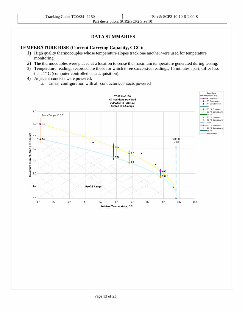
TEMPERATURE RISE (Current Carrying Capacity, CCC):
1) High quality thermocouples whose temperature slopes track one another were used for temperature monitoring.
2) The thermocouples were placed at a location to sense the maximum temperature generated during testing. 3) Temperature readings recorded are those for which three successive readings, 15 minutes apart, differ less
than 1° C (computer controlled data acquisition). 4) Adjacent contacts were powered:
a. Linear configuration with all conductors/contacts powered
TC0634--1150All Positions PoweredSCP2/SCR2 (Size 10)Tested at 4.5 amps
6.06.0
4.84.8
4.14.1
3.33.3
3.63.6
2.92.9
2.22.2
1.81.8
0.0
1.0
2.0
3.0
4.0
5.0
6.0
7.0
17 27 37 47 57 67 77 87 97 107 117
Ambient Temperature, ° C
Max
imu
m C
urr
ent,
Am
p p
er C
on
tact
Base Curve
Derated 20 %
RT Peak Amp
RT Derated Amp
Measured Current
65 ° C
65 ° C Peak Amp
65 ° C Derated Amp
75 ° C
75 ° C Peak Amp
75 ° C Derated Amp
Limit
95 ° C Peak Amp
95 ° C Derated Amp
95 ° C
Room Temp
105° CLimit
Useful Range
Room Temp= 18.3 C
Tracking Code: TC0634--1150 Part #: SCP2-10-10-S-2.00-S Part description: SCR2/SCP2 Size 10
Page 14 of 23
DATA SUMMARIES Continued
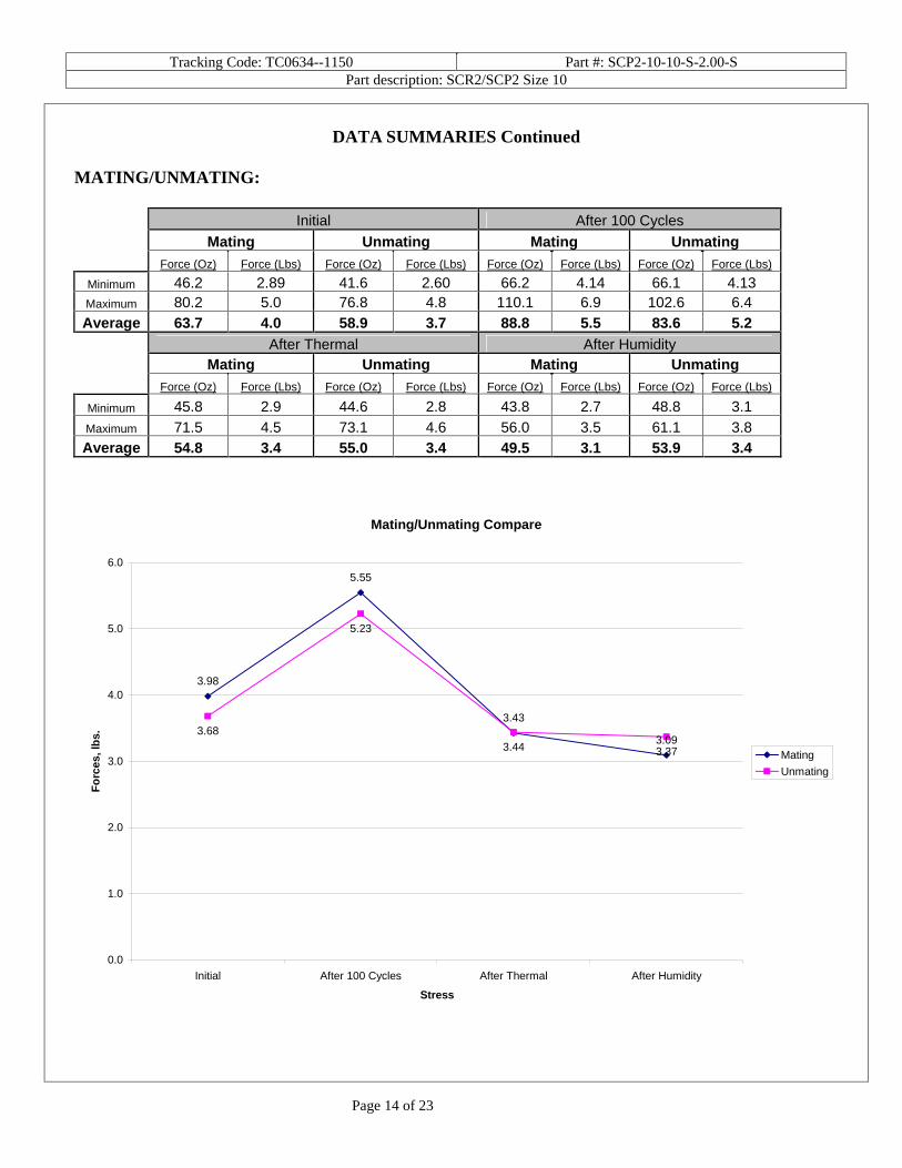
MATING/UNMATING: Initial After 100 Cycles
Mating Unmating Mating Unmating Force (Oz) Force (Lbs) Force (Oz) Force (Lbs) Force (Oz) Force (Lbs) Force (Oz) Force (Lbs)
Minimum 46.2 2.89 41.6 2.60 66.2 4.14 66.1 4.13 Maximum 80.2 5.0 76.8 4.8 110.1 6.9 102.6 6.4 Average 63.7 4.0 58.9 3.7 88.8 5.5 83.6 5.2
After Thermal After Humidity Mating Unmating Mating Unmating Force (Oz) Force (Lbs) Force (Oz) Force (Lbs) Force (Oz) Force (Lbs) Force (Oz) Force (Lbs)
Minimum 45.8 2.9 44.6 2.8 43.8 2.7 48.8 3.1 Maximum 71.5 4.5 73.1 4.6 56.0 3.5 61.1 3.8 Average 54.8 3.4 55.0 3.4 49.5 3.1 53.9 3.4
Mating/Unmating Compare
3.98
5.55
3.43
3.093.68
5.23
3.44 3.37
0.0
1.0
2.0
3.0
4.0
5.0
6.0
Initial After 100 Cycles After Thermal After Humidity
Stress
Fo
rces
, lb
s.
Mating
Unmating
Tracking Code: TC0634--1150 Part #: SCP2-10-10-S-2.00-S Part description: SCR2/SCP2 Size 10
Page 15 of 23
DATA SUMMARIES Continued
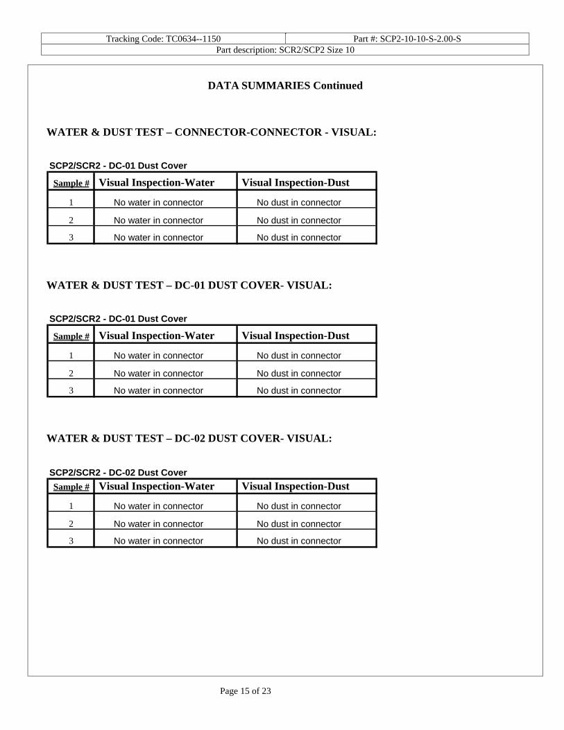
WATER & DUST TEST – CONNECTOR-CONNECTOR - VISUAL:
WATER & DUST TEST – DC-01 DUST COVER- VISUAL:
WATER & DUST TEST – DC-02 DUST COVER- VISUAL:
SCP2/SCR2 - DC-01 Dust Cover
Sample # Visual Inspection-Water Visual Inspection-Dust
1 No water in connector No dust in connector
2 No water in connector No dust in connector
3 No water in connector No dust in connector
SCP2/SCR2 - DC-01 Dust Cover
Sample # Visual Inspection-Water Visual Inspection-Dust
1 No water in connector No dust in connector
2 No water in connector No dust in connector
3 No water in connector No dust in connector
SCP2/SCR2 - DC-02 Dust Cover
Sample # Visual Inspection-Water Visual Inspection-Dust
1 No water in connector No dust in connector
2 No water in connector No dust in connector
3 No water in connector No dust in connector

Tracking Code: TC0634--1150 Part #: SCP2-10-10-S-2.00-S Part description: SCR2/SCP2 Size 10
Page 16 of 23
IR – Connector Only-Tested in Mated Condition Only
Initial, Meg Ohms Thermal, Meg
Ohms Humidity, Meg
Ohms Average 100000 75000 100000
Min 100000 50000 100000
Max 100000 100000 100000
VOLTAGE BREAKDOWN – Connector Only-Tested in Mated Condition Only Initial, VAC Mated Thermal, VAC Mated Humidity, VAC Mated
Breakdown
Voltage DWV Working Voltage
Breakdown Voltage DWV
Working Voltage
Breakdown Voltage DWV
Working Voltage
Average 1250 938 313 1100 825 275 1230 923 308 Min 1200 900 300 1100 825 275 1160 870 290
Max 1300 975 325 1100 825 275 1300 975 325
DURABILITY / LLCR:
Date May 29 2007
May 29 2007
June 26 2007 July 7 2007
Room Temp C 23 23 23 24 RH 57% 57% 53% 45%
Name Tony
Wagoner Tony
Wagoner Tori Meek Tony W. mOhm values Actual Delta Delta Delta
Initial 100 Cycles Thermal Humidity Average 16.8 -0.2 0.5 0.6 St. Dev. 0.7 0.4 0.6 1.3
Min 15.8 -1.9 -1.1 -9.7 Max 19.6 0.8 2.5 3.6
Count 100 100 100 100

Tracking Code: TC0634--1150 Part #: SCP2-10-10-S-2.00-S Part description: SCR2/SCP2 Size 10
Page 17 of 23
DATA
MATING/UNMATING: Initial After 100 Cycles
Mating Unmating Mating Unmating
Sample# Force (Oz)
Force (Lbs)
Force (Oz)
Force (Lbs) Force (Oz) Force (Lbs) Force (Oz) Force (Lbs)
1 54.4 3.40 51.0 3.19 72.8 4.55 69.4 4.34 2 46.2 2.89 46.1 2.88 70.9 4.43 67.2 4.20 3 56.3 3.52 43.2 2.70 70.7 4.42 67.2 4.20 4 52.8 3.30 41.6 2.60 66.2 4.14 66.1 4.13 5 69.0 4.31 67.8 4.24 110.1 6.88 102.6 6.41 6 70.4 4.40 74.1 4.63 108.0 6.75 100.2 6.26 7 76.2 4.76 62.4 3.90 106.1 6.63 95.0 5.94 8 80.2 5.01 76.8 4.80 102.7 6.42 98.4 6.15 9 60.3 3.77 57.6 3.60 81.3 5.08 78.4 4.90
10 71.4 4.46 68.5 4.28 98.9 6.18 92.0 5.75 After Thermal After Humidity
Mating Unmating Mating Unmating
Sample# Force (Oz)
Force (Lbs)
Force (Oz)
Force (Lbs) Force (Oz) Force (Lbs) Force (Oz) Force (Lbs)
1 48.3 3.02 45.1 2.82 49.0 3.06 48.8 3.05 2 45.8 2.86 44.6 2.79 48.0 3.00 49.6 3.10 3 46.7 2.92 45.6 2.85 45.3 2.83 52.3 3.27 4 46.4 2.90 45.4 2.84 51.2 3.20 55.5 3.47 5 68.8 4.30 73.1 4.57 52.5 3.28 61.1 3.82 6 62.9 3.93 64.5 4.03 56.0 3.50 60.5 3.78 7 71.5 4.47 68.2 4.26 51.7 3.23 59.0 3.69 8 55.7 3.48 60.5 3.78 43.8 2.74 49.3 3.08 9 49.9 3.12 51.5 3.22 50.9 3.18 50.2 3.14
10 52.3 3.27 51.5 3.22 46.6 2.91 53.0 3.31

Tracking Code: TC0634--1150 Part #: SCP2-10-10-S-2.00-S Part description: SCR2/SCP2 Size 10
Page 18 of 23
DATA Continued
IR DATA – Connector Only-Tested in Mated Condition Only
Initial, Meg Ohms Thermal, Meg
Ohms Humidity, Meg
Ohms Sample
# Insulation Resistance
Insulation Resistance
Insulation Resistance
1 100000 50000 100000
2 100000 100000 100000
VOLTAGE BREAKDOWN DATA – Connector Only-Tested in Mated Condition Only
Initial, VAC Mated Thermal, VAC Mated Humidity, VAC Mated
Sample #
Breakdown Voltage DWV
Working Voltage
Breakdown Voltage DWV
Working Voltage
Breakdown Voltage DWV
Working Voltage
1 1300 975 325 1100 825 275 1300 975 325
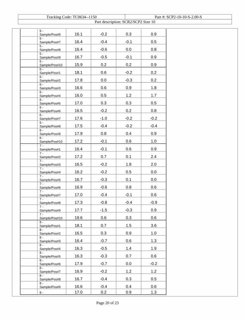
2 1200 900 300 1100 825 275 1160 870 290 DURABILITY / LLCR: mOhm values Actual Delta Delta Delta
Board Position Initial 100
Cycles Thermal Humidity
1 -Sample/Pos#1 16.4 0.4 1.2 0.6
1 -Sample/Pos#2 16.6 -0.3 0.9 0.3
1 -Sample/Pos#3 16.8 0.2 0.9 0.6
1 -Sample/Pos#4 17.9 -0.1 -0.5 -0.8
1 -Sample/Pos#5 16.7 -0.3 1.0 0.7
1 -Sample/Pos#6 16.4 -0.1 0.8 0.2
1 -Sample/Pos#7 17.2 0.3 0.4 0.0
1 -Sample/Pos#8 16.5 -0.4 0.7 0.2
1 -Sample/Pos#9 16.0 0.0 1.5 0.7
1 -Sample/Pos#10 16.9 0.0 1.2 0.8
2 - 16.0 0.3 2.0 0.6

Tracking Code: TC0634--1150 Part #: SCP2-10-10-S-2.00-S Part description: SCR2/SCP2 Size 10
Page 19 of 23
Sample/Pos#1
2 -Sample/Pos#2 16.5 -0.3 1.9 1.3
2 -Sample/Pos#3 16.8 -0.6 1.4 0.5
2 -Sample/Pos#4 16.2 -0.6 1.9 2.1
2 -Sample/Pos#5 16.4 -0.7 1.9 0.5
2 -Sample/Pos#6 16.6 -0.6 1.8 1.0
2 -Sample/Pos#7 16.1 -0.3 2.5 1.9
2 -Sample/Pos#8 16.3 -0.7 0.2 0.4
2 -Sample/Pos#9 16.9 -0.9 0.7 0.8
2 -Sample/Pos#10 16.3 -0.6 0.0 0.4
3 -Sample/Pos#1 17.1 -0.3 0.1 0.5
3 -Sample/Pos#2 16.5 0.2 0.9 1.1
3 -Sample/Pos#3 16.5 -0.2 0.6 0.7
3 -Sample/Pos#4 17.1 -0.6 -0.1 0.9
3 -Sample/Pos#5 16.4 -0.3 0.1 0.6
3 -Sample/Pos#6 16.9 -0.1 0.4 0.6
3 -Sample/Pos#7 16.8 0.0 0.1 0.9
3 -Sample/Pos#8 16.4 -0.2 0.3 0.6
3 -Sample/Pos#9 16.2 0.0 0.6 0.9
3 -Sample/Pos#10 17.2 -0.5 0.9 1.2
4 -Sample/Pos#1 17.9 -0.5 -0.4 0.1
4 -Sample/Pos#2 19.4 -0.4 0.2 0.5
4 -Sample/Pos#3 16.7 -0.3 -0.1 -9.7
4 -Sample/Pos#4 18.2 -0.2 -0.6 0.2
4 -Sample/Pos#5 16.6 0.0 0.5 1.1
4 -Sample/Pos#6 17.2 -0.2 -0.1 0.1
4 -Sample/Pos#7 16.9 0.4 0.2 0.6
4 -Sample/Pos#8 16.6 0.0 0.4 0.8
4 -Sample/Pos#9 16.6 0.5 0.8 1.3
4 -Sample/Pos#10 16.8 -0.1 0.1 0.7
5 -Sample/Pos#1 16.2 0.0 0.2 0.4
5 -Sample/Pos#2 16.1 -0.3 0.6 1.3
5 -Sample/Pos#3 16.8 -0.1 0.2 0.3
5 -Sample/Pos#4 16.1 -0.6 0.2 1.1
5 -Sample/Pos#5 15.8 -0.2 1.0 1.5
Tracking Code: TC0634--1150 Part #: SCP2-10-10-S-2.00-S Part description: SCR2/SCP2 Size 10
Page 20 of 23
5 -Sample/Pos#6 16.1 -0.2 0.3 0.9
5 -Sample/Pos#7 16.4 -0.4 -0.1 0.5
5 -Sample/Pos#8 16.4 -0.6 0.0 0.8
5 -Sample/Pos#9 16.7 -0.5 -0.1 0.9
5 -Sample/Pos#10 15.9 0.2 0.2 0.9
6 -Sample/Pos#1 18.1 0.6 -0.2 0.2
6 -Sample/Pos#2 17.8 0.0 -0.3 0.2
6 -Sample/Pos#3 16.6 0.6 0.9 1.8
6 -Sample/Pos#4 16.0 0.5 1.2 1.7
6 -Sample/Pos#5 17.0 0.3 0.3 0.5
6 -Sample/Pos#6 16.5 -0.2 0.2 0.8
6 -Sample/Pos#7 17.6 -1.0 -0.2 -0.2
6 -Sample/Pos#8 17.5 -0.4 -0.2 -0.4
6 -Sample/Pos#9 17.9 0.8 0.4 0.9
6 -Sample/Pos#10 17.2 -0.1 0.6 1.0
7 -Sample/Pos#1 16.4 -0.1 0.6 0.9
7 -Sample/Pos#2 17.2 0.7 0.1 2.4
7 -Sample/Pos#3 16.5 -0.2 1.8 2.0
7 -Sample/Pos#4 16.2 -0.2 0.5 0.0
7 -Sample/Pos#5 16.7 -0.3 0.1 0.0
7 -Sample/Pos#6 16.9 -0.6 0.8 0.6
7 -Sample/Pos#7 17.0 -0.4 -0.1 0.6
7 -Sample/Pos#8 17.3 -0.8 -0.4 -0.9
7 -Sample/Pos#9 17.7 -1.5 -0.3 0.9
7 -Sample/Pos#10 19.6 0.6 0.3 0.6
8 -Sample/Pos#1 18.1 0.7 1.5 3.6
8 -Sample/Pos#2 16.5 0.3 0.9 1.0
8 -Sample/Pos#3 16.4 -0.7 0.6 1.3
8 -Sample/Pos#4 16.3 -0.5 1.4 1.9
8 -Sample/Pos#5 16.3 -0.3 0.7 0.6
8 -Sample/Pos#6 17.9 -0.7 0.0 -0.2
8 -Sample/Pos#7 16.9 -0.2 1.2 1.2
8 -Sample/Pos#8 16.7 -0.4 0.3 0.5
8 -Sample/Pos#9 16.6 -0.4 0.4 0.6
8 - 17.0 0.2 0.9 1.3
Tracking Code: TC0634--1150 Part #: SCP2-10-10-S-2.00-S Part description: SCR2/SCP2 Size 10
Page 21 of 23
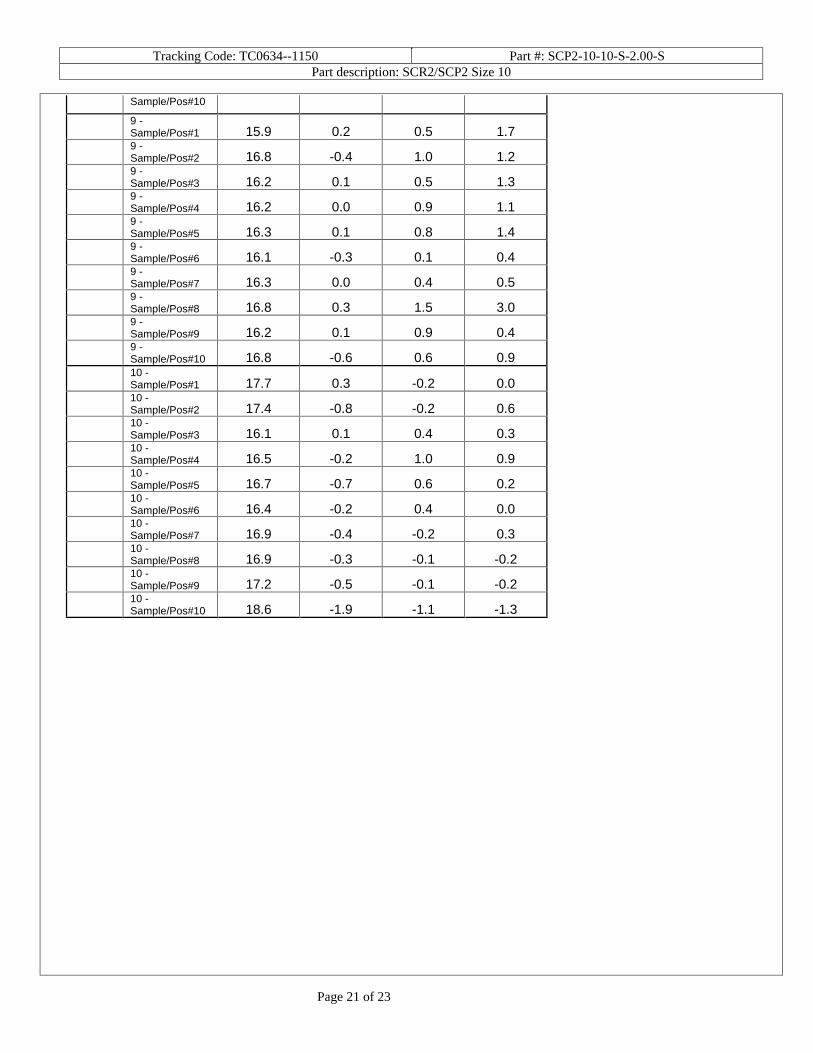
Sample/Pos#10
9 -Sample/Pos#1 15.9 0.2 0.5 1.7
9 -Sample/Pos#2 16.8 -0.4 1.0 1.2
9 -Sample/Pos#3 16.2 0.1 0.5 1.3
9 -Sample/Pos#4 16.2 0.0 0.9 1.1
9 -Sample/Pos#5 16.3 0.1 0.8 1.4
9 -Sample/Pos#6 16.1 -0.3 0.1 0.4
9 -Sample/Pos#7 16.3 0.0 0.4 0.5
9 -Sample/Pos#8 16.8 0.3 1.5 3.0
9 -Sample/Pos#9 16.2 0.1 0.9 0.4
9 -Sample/Pos#10 16.8 -0.6 0.6 0.9
10 -Sample/Pos#1 17.7 0.3 -0.2 0.0
10 -Sample/Pos#2 17.4 -0.8 -0.2 0.6
10 -Sample/Pos#3 16.1 0.1 0.4 0.3
10 -Sample/Pos#4 16.5 -0.2 1.0 0.9
10 -Sample/Pos#5 16.7 -0.7 0.6 0.2
10 -Sample/Pos#6 16.4 -0.2 0.4 0.0
10 -Sample/Pos#7 16.9 -0.4 -0.2 0.3
10 -Sample/Pos#8 16.9 -0.3 -0.1 -0.2
10 -Sample/Pos#9 17.2 -0.5 -0.1 -0.2
10 -Sample/Pos#10 18.6 -1.9 -1.1 -1.3

Tracking Code: TC0634--1150 Part #: SCP2-10-10-S-2.00-S Part description: SCR2/SCP2 Size 10
Page 22 of 23
EQUIPMENT AND CALIBRATION SCHEDULES
Equipment #: THL-02 Description: Temperature/Humidity Chart Recorder Manufacturer: Dickson Model: THDX Serial #: 00120351 Accuracy: Temp: +/- 1C; Humidity: +/-2% RH (0 - 60%) +/- 3% RH (61 - 95%). … Last Cal: 06/16/06, Next Cal: 06/16/07
Equipment #: MO-02 Description: Multimeter /Data Acquisition System Manufacturer: Keithley Model: 2700 Serial #: 0780546 Accuracy: See Manual … Last Cal: 05/12/06, Next Cal: 05/12/07
Equipment #: MO-04 Description: Multimeter /Data Acquisition System Manufacturer: Keithley Model: 2700 Serial #: 0798688 Accuracy: See Manual … Last Cal: 01/31/06, Next Cal: 01/31/07
Equipment #: PS-01 Description: System Power Supply Manufacturer: Hewlett Packard Model: HP 6033A Serial #: (HP) 3329A-07330 Accuracy: See Manual … Last Cal: 05/12/06, Next Cal: 05/12/07
Equipment #: TC090601-103/105 Description: IC Thermocouple-103/105 Manufacturer: Samtec Model: Serial #: TC090601-103/105 Accuracy: +/- 1 degree C … Last Cal: , Next Cal: Equipment #: HPM-01 Description: Hipot Megommeter Manufacturer: Hipotronics Model: H306B-A Serial #: M9905004 Accuracy: 2 % Full Scale Accuracy … Last Cal: 5/12/06, Next Cal: 05/12/07
Tracking Code: TC0634--1150 Part #: SCP2-10-10-S-2.00-S Part description: SCR2/SCP2 Size 10
Page 23 of 23
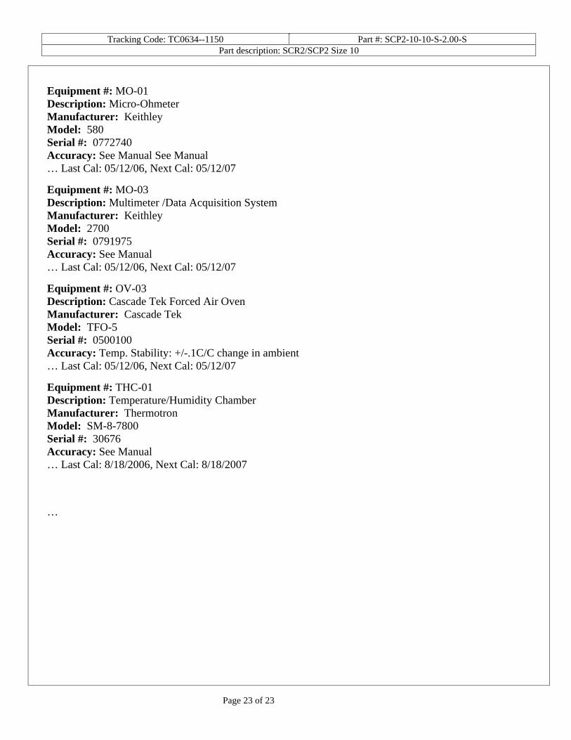
Equipment #: MO-01 Description: Micro-Ohmeter Manufacturer: Keithley Model: 580 Serial #: 0772740 Accuracy: See Manual See Manual … Last Cal: 05/12/06, Next Cal: 05/12/07
Equipment #: MO-03 Description: Multimeter /Data Acquisition System Manufacturer: Keithley Model: 2700 Serial #: 0791975 Accuracy: See Manual … Last Cal: 05/12/06, Next Cal: 05/12/07
Equipment #: OV-03 Description: Cascade Tek Forced Air Oven Manufacturer: Cascade Tek Model: TFO-5 Serial #: 0500100 Accuracy: Temp. Stability: +/-.1C/C change in ambient … Last Cal: 05/12/06, Next Cal: 05/12/07
Equipment #: THC-01 Description: Temperature/Humidity Chamber Manufacturer: Thermotron Model: SM-8-7800 Serial #: 30676 Accuracy: See Manual … Last Cal: 8/18/2006, Next Cal: 8/18/2007
…

This document was created with Win2PDF available at http://www.daneprairie.com.The unregistered version of Win2PDF is for evaluation or non-commercial use only.