Embed Size (px)
Citation preview
Gazetteer Conventions for Street Polygons
Document Version 0.5 (Draft)
Date March 2015
DRAFT Scottish Gazetteer Conventions for Street Polygons 1
Contents
1. Introduction................................................................................................................................ 41.1. Purpose............................................................................................................................. 4
1.2. Background.......................................................................................................................4
1.3. Business Requirements....................................................................................................5
1.4. Project Streams................................................................................................................. 5
1.5. Elementary Level of Capture.............................................................................................6
1.6. Base Mapping................................................................................................................... 7
1.7. Conventions...................................................................................................................... 9
2. Glossary................................................................................................................................... 10
3. Gazetteer model....................................................................................................................... 11
4. Local Street Gazetteer Conventions......................................................................................124.1 Purpose........................................................................................................................... 12
4.2 Content........................................................................................................................... 12
4.3 Street attributes...............................................................................................................13
4.4 USRN.............................................................................................................................. 16
4.5 Record type..................................................................................................................... 16
4.6 Responsible authority......................................................................................................18
4.7 State................................................................................................................................ 18
4.8 Date................................................................................................................................ 18
4.9 Identifier.......................................................................................................................... 18
4.10 Locality and town............................................................................................................20
4.11 Administrative area.........................................................................................................21
4.12 Language........................................................................................................................ 21
4.13 Extremity points...............................................................................................................22
4.14 Street lifecycle................................................................................................................. 24
4.15 Cross-references.............................................................................................................27
4.16 ESU ID............................................................................................................................ 29
4.17 ESU lifecycle................................................................................................................... 29
4.18 Street Polygon Examples................................................................................................30
4.19 ESP Geometry................................................................................................................31
4.20 ESP feature type.............................................................................................................32
4.21 Road status..................................................................................................................... 32
4.22 Adoption date.................................................................................................................. 33
4.23 ESP ID............................................................................................................................ 33
4.24 ESP lifecycle................................................................................................................... 33
document.docx Oliver J Penman, Glasgow City Council 2 of 64Page 2 of 64
5. Geometry.................................................................................................................................. 345.1 Method............................................................................................................................ 34
5.2 ESP Hierarchy................................................................................................................. 38
5.3 Junction Types................................................................................................................38
6. Junction Layouts..................................................................................................................... 396.1 T Junctions...................................................................................................................... 39
6.2 Cross Roads................................................................................................................... 43
6.3 Offset Junctions..............................................................................................................45
6.4 Roundabouts................................................................................................................... 50
6.5 Dual Carriageway Cross Overs.......................................................................................56
document.docx Oliver J Penman, Glasgow City Council 3 of 64Page 3 of 64

1. In t roduct ion
1.1. Purpose
This document outlines proposed conventions for capture and maintenance of a “Polygonised”
representation of Scottish Street Gazetteers presently maintained in linear network format. The
document also presents the full set of street conventions to make it simpler to review the
corresponding rules required for handling street polygons.
The aim of these conventions is to ensure that gazetteer data are maintained to a consistent
standard across Scotland and are usable regionally and nationally.
1.2. Background
The collection of data to form a Street Gazetteer has been in place for a long time; however the
recent maturity of the Addressing Products has brought the position of data collected for the
Street Work Purposes into focus.
Although the Local Authorities collect Street Information for their Corporate Address Gazetteer
(Local Land and Property Gazetteer), this is not always the same data as is held in their Street
Works system. The purpose of the Street Gazetteer in the CAG is simply a mechanism to
attach a property to. The Street Gazetteer for Street works (SWR) is used extensively within
council for a number of purposes.
For the purposes of a CAG, the Street Gazetteer needs to provide a start and end coordinate
for a street. This is known as a Level 1 Gazetteer. This is enough for the CAG to attach a
property to a Street. For the purposes of a Street Work Gazetteer, the street needs to have
shape that matches the road that the Street is modelling. This is known as a Level 3 Gazetteer.
This is a more useful format of the Gazetteer than the Level 1 as the street can be visualised
looking like the Road.
There are a number of business requirements which could benefit from the accurate
representation of roads and the availability of key attribute data. Current street gazetteers use
linear geometry to represent roads, which has limited benefits. A more useful approach would
be to represent roads as polygons and associate roads attributes with these polygons to
generate information based on area.
document.docx Oliver J Penman, Glasgow City Council 4 of 64Page 4 of 64
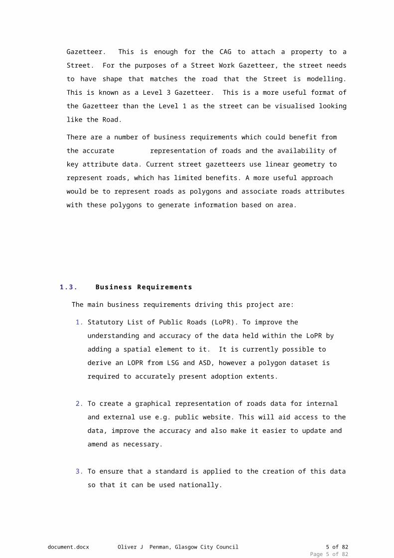
1.3. Business Requirements
The main business requirements driving this project are:
1. Statutory List of Public Roads (LoPR). To improve the understanding and accuracy of
the data held within the LoPR by adding a spatial element to it. It is currently possible to
derive an LOPR from LSG and ASD, however a polygon dataset is required to
accurately present adoption extents.
2. To create a graphical representation of roads data for internal and external use e.g.
public website. This will aid access to the data, improve the accuracy and also make it
easier to update and amend as necessary.
3. To ensure that a standard is applied to the creation of this data so that it can be used
nationally.
4. For SCOTS asset management project the LoPR data will represent one of the biggest
assets in the country and will be used within each authority as a major part of the
Council’s Roads Asset Management System.
5. There are many other potential uses for a detailed street polygon dataset including e.g.
street cleansing operations, waste management, grounds maintenance, accurate
recording of surface types, maintenance planning and costing.
6. Representing existing linear ESUs surface area is a useful attribute for asset
management.
1.4. Project Streams
Initially the project included two streams:-
1. Identification and documentation of the business requirements for holding street
polygon data.
2. Identification and documentation of the conventions for capturing, editing and
maintaining street polygons.
Two groups were initiated to meet the objectives of these streams
1. A small technical group (5 members) elected from a meeting of 15 local authorities
who have already captured street polygons, are in the process of capturing street
polygons or have shown a desire to capture street polygons.
2. A business case group made up of interested stakeholders to produce a business
requirements document supporting the requirements and advantages of capturing
street data as polygons.
document.docx Oliver J Penman, Glasgow City Council 5 of 64Page 5 of 64

1.5. Elementary Level of Capture
It should be noted that the scope of the project is to create conventions detailing the method
and methodology of capturing a polygonised representation of the existing linear street
gazetteers. Therefore in order to get maximum benefit from the capture of street polygons, it is
necessary to integrate them into the existing street gazetteer structure.
A key decision has been made regarding whether polygons should be linked to USRNs (Unique
Street Reference Number) or ESUs (Elementary Street Unit, see 4.13). The method proposed
links polygons to ESUs and as a consequence of their hierarchical geometry uniquely linked to
the corresponding USRNs. Current GIS functionality can be used to ensure that polygons
representing individual ESUs (ESPs) can be ‘aggregated’ to represent the geometry of their
parent USRNs in polygon format.
Street polygons are referred to as Elementary Street Polygons and are handled in a similar
manner to ESUs. Many of the conventions for ESUs have been adopted for ESPs
Linking ESPs uniquely to ESUs will allow access to USRN attribution via the existing ESU cross
references. i.e. An attribute of an ESP will be the ESUID of the corresponding ESU. This link
would allow ESU based attributes to be associated with ESPs which can therefore make USRN
attribution accessible.
It is the case that it is possible for an ESU to be linked to more than one ESP . See example in
6.3.1
Polygons provide a better visual representation of streets than centreline geometry does and it
is required that key attributes of a street are displayed graphically. These include road status
and road class. It is normally not good practice to store a data item twice but road status is
included as an ESP attribute. This is held in the Associated Street Data Type 51 record but
ASD is not available to all street gazetteers and if status does not apply to whole road, the
definition is imprecise. Capture Status
Scotland’s local authorities are at various stages of data capture for street polygons at present.
1. Authorities who have captured street polygons covering the extent of their local authority
boundary that represent a polygonised version of their linear street gazetteer with
polygons ‘split’ at ESUs. Although these have been captured in the absence of any
centrally defined standards.
2. Authorities who have captured a polygonised version of the statutory ‘List of Public
Roads’ (LoPR) i.e. graphical representation of road adoptions, stopping ups and in some
cases private roads. In most cases these polygons have not been ‘split’ at ESU level.
Although these have been captured in the absence of any centrally defined standards
3. Authorities who have already commenced or have plans to capture a polygonised street
dataset
document.docx Oliver J Penman, Glasgow City Council 6 of 64Page 6 of 64

4. Authorities who have neither captured polygons nor have any plans to.
These conventions set out to create a set of rules and recommendations enabling the consistent capture of street polygons for those authorities who have not yet commenced capturing this data i.e. a set of directives for data capture starting ‘from scratch’.
Consequently the conventions outline the rules for those authorities who have began or
completed data capture to amend and edit existing data to create national consistency.
It should be noted that to ensure consistent capture of street polygon datasets representing
linear street gazetteer geometry it is necessary that there is consistency in the capture and
maintenance of this linear geometry e.g. some authorities do not create separate ESUs at
changes in maintenance responsibility while others do. The document therefore includes existing conventions for local street gazetteer
These conventions do not intend to recommend changes to existing conventions for linear
street gazetteers; rather the intention is to adhere to these in order to create consistent
corresponding polygons. There are though exceptions to this caused by the differing nature of
the polygon geometry which will be highlighted and explained later in this document.
1.6. Base Mapping
OS MasterMap will be used as a common source of street polygon data, although other
mapping products, including paper maps can be used as reference and investigation. At
present all Local Authorities receive OS MasterMap Topography Layer as part of the One
Scotland Mapping Agreement and currently no other large scale polygonised dataset exists.
OS MasterMap Topography Layer has been developed in response to the need for a national
topographic dataset that offers customers a more sophisticated type of data that represented
the world in a more realistic way and was more aligned to the increasing use and functionality
of GIS and spatial database technology within organisations. Many customers use geographic
products as a basis to derive their own data, which can be time consuming and inefficient
where features in the data are amalgamations of more than one real-world feature or even
parts of real-world features. Where the feature represents a real-world feature that has an
‘area’, such as a building or a parcel of land, the feature is represented in the data as a
polygon. OS MasterMap Topography Layer is used extensively by businesses and
organisations that need to relate their activities and/or their assets to the physical environment.
Many organisations need to derive their own GI from OS MasterMap Topography Layer. They
use the individual features that Ordnance Survey provides to form the building blocks for their
own sets of GI. Many local- and central-government organisations use it this way. Once they
have the physical feature or group of features they are interested in, they can attach their own
attribution to that already provided with the product. When this kind of data association takes
document.docx Oliver J Penman, Glasgow City Council 7 of 64Page 7 of 64

place, it can lead to efficiencies in storing and using data. It can also enable data to be shared
more easily between and within organisations.
Street polygons will be derived from OS MasterMap Topography Layer by extracting the roads,
tracks and paths features. To date all authorities who have captured or have commenced
capture have used this method. This is then edited to represent the geometrical extents of
polygons. Care should be taken in rural areas when using this method as the OSMM geometry
does not always accurately reflect the layout of the carriageway and verges in these areas. In
this case the polygons will require to be captured using whatever extra information is available
from other sources or by making assumptions as to road widths.
It should be noted that the roads, tracks and paths polygon features layers do not presently
geometrically match the footprint of previous polygon datasets which have been captured in all
cases e.g. list of public roads. The existing OSMM polygons also represent junctions contrary to
the rules of existing street gazetteer conventions. These factors signify a considerable amount
of editing to OSMM features to truly represent polygon extents of existing linear street
geometry.
OS currently take the information from the OneScotland Gazetteer and process this with other
information into their AddressBase product. It is envisaged that a similar procedure may be
possible with local authority street polygon datasets being made available to OS to enhance or
expand the existing MasterMap suite of products. This may include OS, in conjunction with
stakeholders, developing ‘batch’ process’ to automate a percentage of the data capture process
to reproduce geometry of existing street polygon data using existing OSMM polygons. The
percentage of the total coverage that will be suitable for such batch process is as yet unknown;
although during the production of conventions it has become apparent that this may become
challenging at ‘complex’ junctions and roundabouts.
All OS MasterMap products contain a field holding TOIDs. Every feature has a unique common
reference (a TOID) which enables the layers to be used together i.e. each polygon, line. Point
or annotation has an identifier that uniquely identifies it. There is therefore the issue that if there
is a requirement to ‘split’ OSMM polygons to represent street gazetteer geometry the TOID
reference will no longer be unique.
Attributes of street polygon datasets will match those of existing street gazetteers apart from
those which are not relevant to polygon data e.g. length, start, end. The unique identifier linking
both datasets will be ESUID.
document.docx Oliver J Penman, Glasgow City Council 8 of 64Page 8 of 64
1.7. Conventions
Three categories of convention are presented in this document, which indicate the
requirements of the OneScotland Gazetteer and also indicate best practice to support
widespread local use of the gazetteer
Category Explanation
Mandatory Compliance with this convention is compulsory for street polygons.
Non-compliance with this convention may result in local records being
rejected from any future national combined polygon dataset.
Recommended Compliance with this convention is recommended for street polygons.
Non-compliance with this convention will result in local records being
accepted into any future national combined polygon dataset but a
warning may be issued.
Guidance Compliance with this convention is not compulsory for street polygons
but conventions encourage best practice.
document.docx Oliver J Penman, Glasgow City Council 9 of 64Page 9 of 64

2. Glossary
ASD Associated Street Data
BLPU Basic Land and Property Unit
CAG Corporate Address Gazetteer (popular name for a local property gazetteer)
ESU Elementary Street Unit
ESUID Elementary Street Unit ID
ESP Elementary Street Polygon
ESPID Elementary Street Polygon ID
GIS Geographic Information System
LoPR List of Public Roads
LPI Land and Property Identifier
LSG Local Street Gazetteer
NLPG National Land and Property Gazetteer
NSG National Street Gazetteer
OSG One Scotland Gazetteer
OSMM Ordnance Survey MasterMap
PAO Primary Addressable Object
SAO Secondary Addressable Object
SDTF Scottish Data Transfer Format
SNN Street Naming and Numbering
SRWR Scottish Road Works Register
TOID OS MasterMap Topographic Identifier
UPRN Unique Property Reference Number
USRN Unique Street Reference Number
document.docx Oliver J Penman, Glasgow City Council 10 of 64Page 10 of 64

Street
Street Reinstatement
(52)
Street Special
Designation(53)
Street (11)
Street X Ref(12)
ESU Coord(12)
ElementaryStreet
Unit (13)
Street Descriptor
(15)
ElementaryStreet
Polygon (A)
ESPVertex (B)
Street Reinstatement
(52)
Street Special
Designation(53)
Street (11)
Street X Ref(12)
ESU Coord(14)
ElementaryStreet
Unit (13)
Street Descriptor
(15)
ElementaryStreet
Polygon (A)
ESPVertex (B)
Street Maintenance
Responsibility
(51)
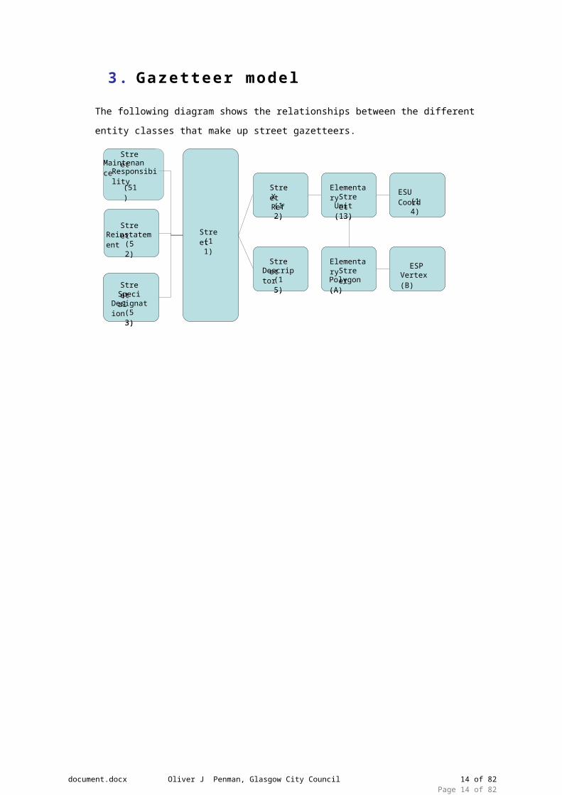
3. Gazet teer model
The following diagram shows the relationships between the different entity classes that make
up street gazetteers.
document.docx Oliver J Penman, Glasgow City Council 11 of 64Page 11 of 64

4. Local S t reet Gazet teer Convent ions
4.1 Purpose
This section presents conventions for Scottish street gazetteers. Conventions are excluded for
Public Rights of Way (not applicable in Scotland) and Associated Street Data (see Ref. Doc. 8)
In Scotland, Local Street Gazetteers (LSG) are created and maintained by local authorities.
They cover all streets in the authority’s geographic area regardless of maintenance
responsibility - for instance, some streets are maintained by the Scottish Government not local
authorities. LSGs have two primary users, whose requirements have influenced these
conventions:
To comply with the New Roads & Street Works Act, the Scottish Road Works Register (SRWR)
holds a copy of 32 LSGs plus associated street data (ASD). This is an electronic register that
records street works carried out by local authorities and utilities.
To comply with BS7666 requirements, property gazetteers are dependent on LSGs to provide a
property record’s street, locality, town, and administrative area information.
4.2 Content
There are three categories of content requirement:
Content
Requirement
Explanation
Mandatory These streets must be included in local street gazetteers. Error
notifications can be issued by the SRWR if one of these street types is
found missing.
Recommended It is recommended that these streets are recorded in local street
gazetteers. Warning notifications can be issued by the SRWR if one of
these street types is found missing.
Guidance These streets may or may not be recorded in local street gazetteers,
according to local requirements. There are no current national
requirements for these streets.
To meet the requirements of the New Roads & Street Works Act, each Roads Authority must
register public roads and prospective public roads. It is also recommended that Roads
Authorities should register all private roads with a public right of passage. Where such private
roads are named, they will need to be included to meet property gazetteer addressing
requirements. The following table seeks to clarify content with specific examples.
document.docx Oliver J Penman, Glasgow City Council 12 of 64Page 12 of 64

Street
Category
Notes and examples Content
Requirement
Classified A, B, C or M roads Mandatory
Unclassified U roads Mandatory
Prospective public
e.g. Development site roads that have been built in
accordance with a valid road construction consent but
have not yet been adopted
Mandatory
Private Maintained by private owner(s) but with a public right of
passage
Recommended
Cycle track /Footpath
Where not part of a street. Note that footways and cycle
ways adjacent to streets are taken to be part of the parent
street.
Mandatory (if on statutory list
of public roads)
Recommended (if private)
Service Side roads etc. Mandatory
Roundabout Mandatory
Slip Mandatory
Indoor Where required locally for a useful address Guidance
Private access
Where access is provided to more than one property.
Note that a drive to a single property is not a street (see
BS7666-1:2006 section 3.7). A private access differs from
a private road in that it can be ‘closed’ to the public if
desired by the owner.
Guidance
Proposed Guidance
4.3 Street attr ibutes
BS7666:2006 specifies mandatory (M), optional (O), and conditional (C) attributes for Streets.
Both England and Wales (NLPG) and Scotland have extended BS7666:2006 with some
additional Street attributes.
The tables below clarify whether there is an obligation to populate each attribute according to
BS7666:2006, the NLPG, and in Scotland. The tables are structured according to SDTF and
cover the geometry and relationship between a street and an elementary street unit (a subset of
a street).
document.docx Oliver J Penman, Glasgow City Council 13 of 64Page 13 of 64
BS67666 attribute SDTF field (11) BS7666 NLPG Scotland
USRN USRN M M M
Record type RECORD_TYPE M M M
Responsible authority CUSTODIAN_CODE M M M
State STATE O O O
Current state date STATE_DATE O C C
Street classification STREET_CLASSIFICATION O O N/A
Entry date ENTRY_DATE M M M
Update date LAST_UPDATE_DATE M M M
Start date START_DATE M M M
End date END_DATE O C C
Extremity point 1 START_X
START_Y
M M M
Extremity point 2 END_X
END_Y
M M M
External cross-reference
O N/A N/A
BS67666 attribute SDTF field (15) BS7666 NLPG Scotland
Identifier DESCRIPTOR M M M
Locality LOCALITY C C C
Town TOWN C C C
Administrative area ADMINISTRATIVE_AREA C M M
Language LANGUAGE O M M
Attribute SDTF field (12) BS7666 NLPG Scotland
Cross reference type XREF_TYPE N/A M M
Cross reference XREF_ID N/A M M
document.docx Oliver J Penman, Glasgow City Council 14 of 64Page 14 of 64
BS67666 attribute SDTF field (13) BS7666 NLPG Scotland
ESU ID ESUID M M M
Update date LAST_UPDATE_DATE M M M
End date END_DATE O C C
Extremity point 1 START_X
START_Y
M M M
Extremity point 2 END_X
END_Y
M M M
Entry date ENTRY_DATE M M M
Start date START_DATE M M M
State N/A O N/A N/A
Current state date N/A O N/A N/A
Street classification N/A O N/A N/A
Description N/A O N/A N/A
External cross-reference
N/A O N/A N/A
BS67666 attribute SDTF field (14) BS7666 NLPG Scotland
Coordinated point X_COORDINATE
Y_COORDINATE
O M C
4.4 USRN
The Unique Street Reference Number (USRN) is the primary key of a street record.
ID Convention Category
4.4.1 A USRN is within the range allocated by the UK Government to
the authority that originally created the street. See Appendix A.
Mandatory
4.4.2 Each USRN is unique within the UK and is not re-used. Mandatory
4.4.3 The USRN for a street is never changed apart from the Lifecycle
changes described in the Street Lifecycle section.
Mandatory
document.docx Oliver J Penman, Glasgow City Council 15 of 64Page 15 of 64

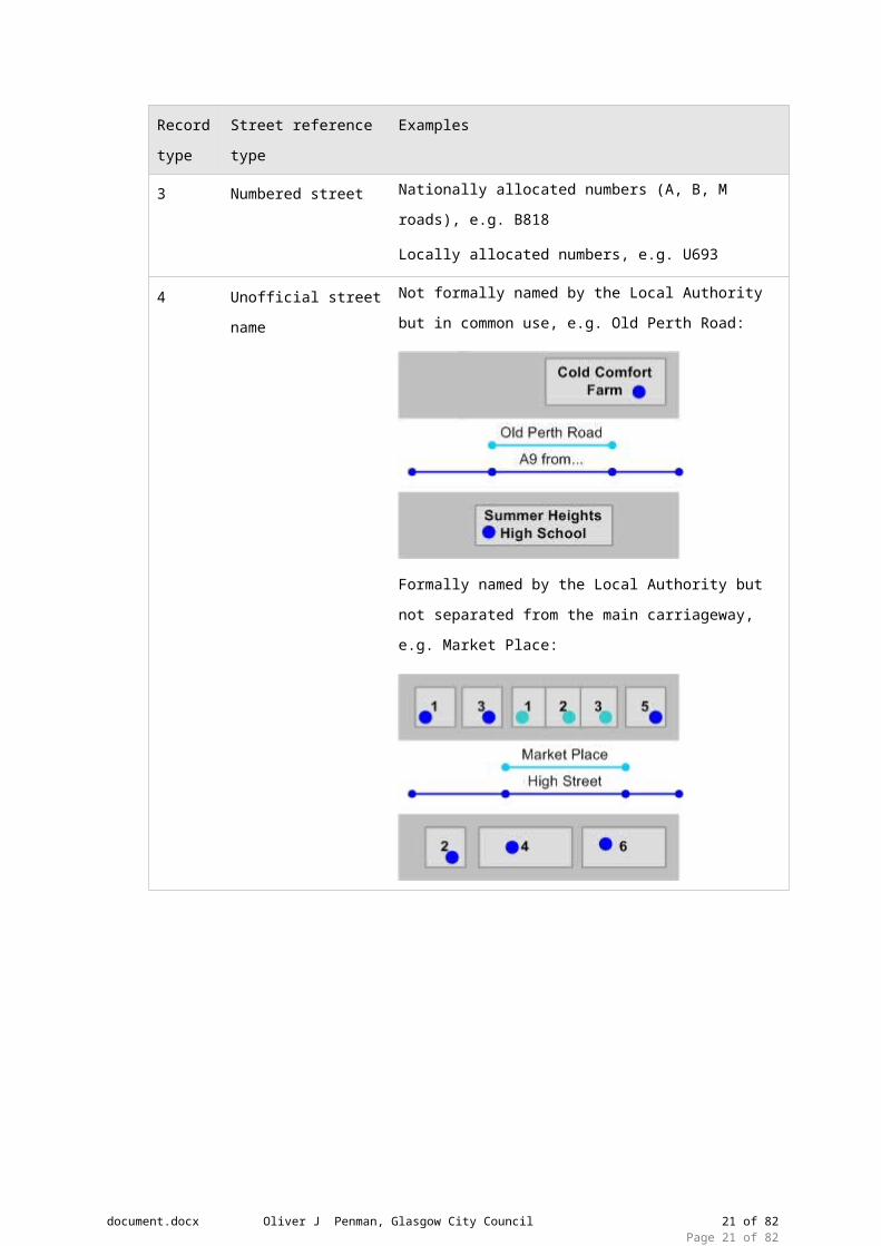
4.5 Record type
According to BS7666-1:2006 section 6.7.2, there are four record types, which identify the type
of street reference:
Record
type
Street reference type Examples
1 Designated street
name
Formally named by a Local Authority’s Street Naming and
Numbering Service, e.g. High Street or Tower
Roundabout
2 Described street A9 from High Street to A72
Cycle track from B341 to Main Road
3 Numbered street Nationally allocated numbers (A, B, M roads), e.g. B818
Locally allocated numbers, e.g. U693
4 Unofficial street name Not formally named by the Local Authority but in common
use, e.g. Old Perth Road:
Formally named by the Local Authority but not separated
from the main carriageway, e.g. Market Place:
document.docx Oliver J Penman, Glasgow City Council 16 of 64Page 16 of 64

Record
type
Street reference type Examples
ID Convention Category
4.5.1 A USRN has a record type of :
1, 2, 3 or 4.
Note that record type 9 is not used in Scotland.
Mandatory
4.5.2 A record type 3 exists for:
every road of classification M, A, or B
every road where the Roads Authority has allocated a number
Mandatory
4.6 Responsible authority
The responsible authority code identifies the authority that is currently responsible for the
gazetteer record. Note that this may not be the authority currently responsible for maintaining
the road.
ID Convention Category
4.6.1 A responsible authority code is allocated to each authority by
the UK Government. See Appendix A.
Mandatory
document.docx Oliver J Penman, Glasgow City Council 17 of 64Page 17 of 64

4.7 State
Currently, State is used in Scotland to flag streets that are under construction. Other State
codes may be introduced in the future.
ID Convention Category
4.7.1 State is populated with:
0 or null = no state
1 = prospective or under construction
2 = open
4 = permanently closed
Mandatory
4.8 Date
ID Convention Category
4.8.1 Current state date is populated if state is 1 Mandatory
4.8.2 Current state date is not before entry date. Mandatory
4.8.3 Last update date must be the same as or after the entry date Mandatory
4.8.4 Street end date must be the same as or after street start date Mandatory
document.docx Oliver J Penman, Glasgow City Council 18 of 64Page 18 of 64

4.9 Identif ier
A street’s Descriptive Identifier is made up of the following BS7666-1:2006 elements: Identifier
Language, Locality, Town, and Administrative Area. Identifier is the street name, number, or
description.
document.docx Oliver J Penman, Glasgow City Council 19 of 64Page 19 of 64

ID Convention Category
4.9.1 Descriptive identifiers (combination of Identifier, Locality,
Town, and Administrative Area) are unique within Britain.
Mandatory
4.9.2 The identifier of a street with a record type 1 matches the
official Street Naming and Numbering record, where this exists.
Note that punctuation is discouraged (see Formatting in the
General section)
Mandatory
4.9.3 The identifier of a street with a record type 2 provides
sufficient information to uniquely identify the street.
The identifier either describes the end points or the general
location and may include key words such as: from, to, adjacent
to, next to, between, rear, alongside, passing across, joining,
via, with branch to.
Guidance
4.9.4 If a street with a record type 2 has been allocated a road
number, the identifier starts with the road number.
Recommended
4.9.5 If the identifier of a street with a record type 2 includes a road
number for a C class, unclassified or other road, a ‘Z’ prefix is
not inserted before the road number.
Recommended
4.9.6 The identifier of a street with a record type 3 does not
exceed 12 characters
Recommended
4.9.7 The identifier of a street with a record type 3 is:
the nationally allocated classification number starting with A, B,
or M
the local Roads Authority allocated number prefixed with an
additional ‘Z’ (see BS7666-1:2006 6.6.5.3)
Mandatory
4.9.8 The identifier of a street for a C class road begins with ‘ZC’ Mandatory
4.9.9 The identifier of a street for an unclassified class road starts
with a ‘ZU’
Guidance
4.9.10 In the identifier for A-class trunk roads, the suffix ‘T’ is added
without a space or brackets, e.g. A9T
Mandatory
document.docx Oliver J Penman, Glasgow City Council 20 of 64Page 20 of 64
4.9.11 If a street with a record type 3 runs through multiple
authorities, the authority name is not included in the identifier. The authority can be identified via administrative area or
responsible authority.
Mandatory
4.10 Locality and town
The purpose of the locality and town attributes is to provide a spatial reference for a street to
identify it uniquely and to form a useful property address. These fields are not mandatory in
Scotland (a difference from England and Wales, where town is mandated) but are strongly
encouraged wherever possible - especially for Type 2 streets - to help SRWR users easily
locate streets and for property gazetteer users to locate addresses.
Locality and town may be used flexibly as ‘area 1’ and ‘area 2’ to represent a wide variety of
geographic areas that will be meaningful to gazetteer users. Localities and towns may evolve
as property development occurs and these changes should be reflected in the Street Gazetteer
as necessary.
The following examples aim to clarify the types of area likely to be found in each field. Note that
some types of area may appear as either a locality or a town or depending on the local
geographical context (e.g. Glens).
document.docx Oliver J Penman, Glasgow City Council 21 of 64Page 21 of 64

A Locality represents a lower level geographic area.
Examples:
Suburbs (Cornton)
Small settlements and surrounds (Blairdaff)
Small rural areas (Glen Ogil)
Industrial estates (Springkerse Industrial Estate)
Where the PAO/SAO is needed for other address elements, the following can also be held as
a locality:
Rural estates (Keir Estate)
Shopping centres (Thistles Centre)
Educational campuses (Stirling University)
Caravan parks (Dunnikier Caravan Park)
If required for a useful address, a town is added to the street gazetteer to represent a higher
level geographic area that may contain one or more lower level geographic areas (localities).
Examples:
Cities (Stirling)
Islands (Isle of Mull)
Large settlements and surrounds (Hamilton)
Large rural areas (Glen Clova)
document.docx Oliver J Penman, Glasgow City Council 22 of 64Page 22 of 64

ID Convention Category
4.10.1 Locality is populated for all street records where it will aid
street or property addressing, except for streets with a record type 3 that cross multiple localities.
Recommended
4.10.2 Town is populated for all street records, except for streets with
a record type 3 that cross multiple towns.
Mandatory
4.10.3 Locality is not populated unless town is also populated. Mandatory
4.10.4 Authorities liaise to represent locality and town consistently
across and within authority boundaries.
Recommended
4.10.5 Locality or town do not contain modifier words such as ‘by’ or
‘near’.
Recommended
4.10.6 The same description is not used as a locality and a town within the same record.
Mandatory
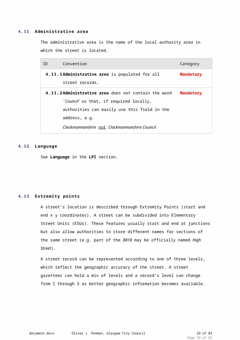
4.11 Administrative area
The administrative area is the name of the local authority area in which the street is located.
ID Convention Category
4.11.1 Administrative area is populated for all street records. Mandatory
4.11.2 Administrative area does not contain the word ‘Council’ so
that, if required locally, authorities can easily use this field in
the address, e.g.
Clackmannanshire not Clackmannanshire Council
Mandatory
4.12 Language
See Language in the LPI section.
document.docx Oliver J Penman, Glasgow City Council 23 of 64Page 23 of 64

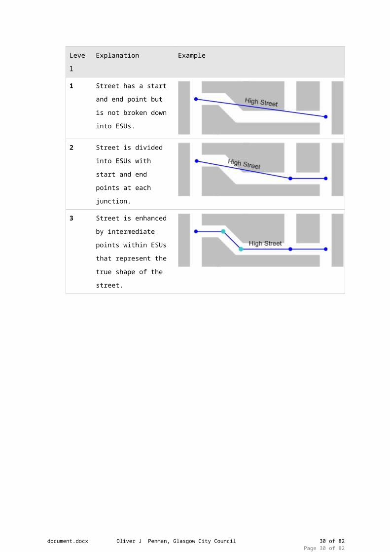
4.13 Extremity points
A street’s location is described through Extremity Points (start and end x y coordinates). A
street can be subdivided into Elementary Street Units (ESUs). These features usually start and
end at junctions but also allow authorities to store different names for sections of the same
street (e.g. part of the B818 may be officially named High Street).
A street record can be represented according to one of three levels, which reflect the
geographic accuracy of the street. A street gazetteer can hold a mix of levels and a record’s
level can change from 1 through 3 as better geographic information becomes available.
Level Explanation Example
1 Street has a start and
end point but is not
broken down into ESUs.
2 Street is divided into
ESUs with start and end
points at each junction.
3 Street is enhanced by
intermediate points within
ESUs that represent the
true shape of the street.
document.docx Oliver J Penman, Glasgow City Council 24 of 64Page 24 of 64

document.docx Oliver J Penman, Glasgow City Council 25 of 64Page 25 of 64

ID Convention Category
4.13.1 To facilitate map-based viewing in the SRWR, a new street
record is entered with Level 2 or 3 geometry, even if this is
initially approximate and needs to be revised later.
Recommended
4.13.2 An ESU does not contain branches. It must not extend across:
A junction
A point where there is a change in the maintenance
responsibility
Where the street name or number changes
An authority boundary
A town or locality boundary
Mandatory
4.13.3 ESUs are connected where roads that are open to vehicles join
and also where roads that are open to vehicles join those that
are closed or restricted to vehicles e.g.
Recommended
4.13.4 An ESU should not be broken except at the locations
described above.
Recommended
4.13.5 For dual carriageways (or roads separated by multiple central
islands), ESUs are created for each carriageway. However,
separate USRNs are only created for each carriageway if they
have different names.
Recommended
4.13.6 For service roads that share a name with the parent street,
ESUs are created for the service road. However, separate
USRNs are created for each road if they have different names.
Note that if a service road is officially named, properties
accessed from the service road use that name as their street
name.
Recommended
4.13.7 Slip roads have the same USRN as the adjoining street
sharing the maintenance responsibility (e.g. part of a trunk
road if both are under the same trunk road operator), unless
there is a requirement for the slip road to be separately
identified.
Recommended
document.docx Oliver J Penman, Glasgow City Council 26 of 64Page 26 of 64

ID Convention Category
4.13.8 Where roundabouts (other than mini roundabouts) do not
form part of a named road or have an official name, they have
their own Type 2 USRN.
Recommended
document.docx Oliver J Penman, Glasgow City Council 27 of 64Page 27 of 64

4.14 Street l ifecycle
document.docx Oliver J Penman, Glasgow City Council 28 of 64Page 28 of 64
ID Convention Category
4.14.1 When a new street is being constructed:
a new street is added to the street gazetteer as soon as it is
needed by the property gazetteer. This is usually before or
shortly after Street Naming and Numbering has assigned a new
street name:
The entry date and start date are populated
Mandatory
4.14.2 When a major new road scheme is to be constructed:
It may be appropriate to add new streets to the street gazetteer
to show the location and layout of the new scheme.
Streets are given descriptions indicating when the scheme would
be finished e.g. New road from A to B opening Spring 2011
The entry date and start date are populated. In this case start date is the date when approval was given or construction
started. It should be on or before the present day.
The State field is set to 1 (prospective or under construction).
The ESUs would be attached to the existing road network when
the scheme was completed or in stages as construction
progressed. The new ESUs would the replace old and the state
field would be set to 2.
Guidance
4.14.3 When a street’s descriptive identifier changes due to error or
official renaming, or a street’s geometry changes:
a new USRN is not created. Instead, the affected street fields
are edited and update date changed., e.g.
If a street has been renamed, a type 4 record may be created for
the old name.
Mandatory
document.docx Oliver J Penman, Glasgow City Council 29 of 64Page 29 of 64
ID Convention Category
4.14.4 If a street needs to be extended:
the ESU geometry is changed for one or more existing streets
and extremity points updated. A new USRN is not required, e.g.
Mandatory
4.14.5 When a street no longer exists:
the end date is populated
if the street record was created in error or the street never
existed, the record can be deleted from the gazetteer. If a
legitimate record, it remains in the gazetteer with an end date.
Mandatory
4.14.6 When a street is split:
two new USRNs are created (even if one of the streets retains
its name)
the old USRN is closed (end date populated), e.g.
If a street is split for a town or locality, the preference is to split
at a:
Street junction
Physical feature that can be easily recognized by SRWR users,
such as a bridge, river, or access to a property
Note that Type 2 descriptions should be actively maintained if
there are changes to the name of the referenced physical
feature.
Mandatory
document.docx Oliver J Penman, Glasgow City Council 30 of 64Page 30 of 64

ID Convention Category
4.14.7 When two or more streets are merged:
one new USRN is created (even if one of the original names is
retained for the new street)
the old USRNs are closed (end date populated), e.g.
Mandatory
document.docx Oliver J Penman, Glasgow City Council 31 of 64Page 31 of 64

4.15 Cross-references
There are three types of cross-references in street gazetteers that are used to link sections of a
street, as described below:
XREF
Type
Use Example
1 Used in ‘Level 1’ street
gazetteers to link a
USRN to another USRN.
A single stretch of road may include a number of
different road types, e.g.
a designated street name (High Street)
a numbered road (A38)
an unofficial name (Market Place)
2 Used in ‘Level 2 or 3’
street gazetteers to link
an individual ESU to a
USRN.
Using the same example above but, this time, Market
Place forms only part of High Street.
document.docx Oliver J Penman, Glasgow City Council 32 of 64Page 32 of 64

ID Convention Category
4.15.1 Cross reference type is populated with:
1 (Street)
2 (ESU)
Mandatory
4.15.2 All Street records are cross-referenced to their constituent ESUs Mandatory
4.15.3 A record type 3 is cross-referenced to one or more record types 1 or 2
Mandatory
4.15.4 A record type 4 is cross-referenced to one or more record types 1 or 2
Mandatory
4.15.5 An ESU can not be cross-referenced to more than one open
Street of the same record type for types 1, 2 or 3 (e.g. can not
reference two type 1’s).
However, an ESU can be cross referenced to more than one
record type 4.
Mandatory
4.16 ESU ID
ID Convention Category
4.16.1 The ESU ID is unique within Scotland and is never re-used. Mandatory
4.16.2 To easily create a unique, 14 digit number, the ESU ID can be
derived from a grid reference, such as the original mid-point of
the ESU. However, the ESU ID does not then change if the mid-
point changes.
Guidance
document.docx Oliver J Penman, Glasgow City Council 33 of 64Page 33 of 64

4.17 ESU l i fecycle
ID Convention Category
4.17.1 When a new ESU is added, a new ESU ID is created Mandatory
4.17.2 When an ESU is changed, the ESU ID does not change Mandatory
4.17.3 If an ESU needs to be extended, the ESU ID does not change Mandatory
4.17.4 When an ESU no longer exists, the ESU end date is
populated. The old ESU ID is not re-used.
Mandatory
4.17.5 When an ESU is split, the old ESU is closed and two new ESUs
are created. The old ESU ID is not re-used.
Mandatory
4.17.6 When two or more ESUs are merged, the old ESUs are closed
and one new ESU is created. The old ESU IDs are not re-used.
Mandatory
4.18 Street Polygon Examples
The following examples illustrate how carriageways and footways should be split into polygons
at junctions, crossroads and roundabouts. Where the polygons are split will depend on:
(a) The identifier(s) of each section of road. Each section will have:
Polygon Attribute Fields
Street Details AttributeESPID M
ESUID M
Record_Type Type 1 / Type 2 / Type 3 / Type 4 R
document.docx Oliver J Penman, Glasgow City Council 34 of 64Page 34 of 64

Descriptor M
Start Date M
End Date R
Entry Date M
Last Updated M
State Under Construction / Unknown / Other M
Class Open to Vehicles / Restricted Access / Pedestrian / Pedestrian and Cycle Track
M
Hierarchy Strategic / Main / Secondary/Prestige/Primary etc.
R
Speed Limit 10 / 15 / 20 / 30 / 40 / 50 / 60 / 70 O
Urban / Rural Urban / Rural R
Clipped ESU Length XXX.X (m) O
Average Width XX.X (m) O
Area XXX.X (m) O
Dual Carriageway Y / N O
Route Number Numerical Value O
Classification A / B / C / U O
Feature_Type See 4.20.1 M
Maintenance Responsibility
Adopted Date Move in table above R
Road Status Public / PMR / Private M
document.docx Oliver J Penman, Glasgow City Council 35 of 64Page 35 of 64

4.19 ESP Geometry
ID Convention Category
4.19.1 ESPs must not overlap. An exception to this is the case of
roads with a vertical displacement e.g. Multi level junctions,
flyovers, underpasses etc. In these cases only the geometrical
representation will overlap and not the physical extent.
Mandatory
4.19.2 An ESP must not extend across:
A point where there is a change in the maintenance
responsibility
Where the street name or number changes
An authority boundary
A town or locality boundary
Mandatory
4.19.3 An ESP should not be broken except at the locations described
above and exceptions made which will be explained later in
this document
Recommended
document.docx Oliver J Penman, Glasgow City Council 36 of 64Page 36 of 64

4.20 ESP feature type
The feature type identifies the type of area defined by the polygon.
ID Convention Category
4.20.1 An ESP has a feature type of:
1 (carriageway)
2 (footway)
3 (footpath)
4 (verge)
5 (service strip)
6 (swale)
7 (cycle track)
8 (visibility splays)
9 (section 51 permissions)
10 (central reservation – landscaping hard or soft)
Mandatory
document.docx Oliver J Penman, Glasgow City Council 37 of 64Page 37 of 64

4.21 Road status
The road status identifies the maintenance responsibility of a feature.
ID Convention Category
4.21.1 An ESP has a road status of:
1 (public road)
2 (prospective public road)
3 (private road)
4 (trunk)
Mandatory
4.22 Adoption date
The adoption date is the date on which the local authority became responsible for maintenance
of the feature.
ID Convention Category
4.22.1 Adoption date is not before start date.
Start date is the date when approval was given or construction
started. It should be on or before the present day.
Mandatory
4.23 ESP ID
ID Convention Category
4.23.1 The ESP ID is unique within Scotland and is never re-used. Mandatory
4.23.2 To easily create a unique digit number, the ESP ID will be
similar to USRN allocation where authorities are allocated a
range authority code (same as USRN) Allocate by sequential
numbering
Mandatory
document.docx Oliver J Penman, Glasgow City Council 38 of 64Page 38 of 64

4.24 ESP li fecycle
ID Convention Category
4.24.1 When a new ESP is added, a new ESP ID is created. Mandatory
4.24.2 When an ESP is changed, the ESP ID does not change. Mandatory
4.24.3 If an ESP needs to be extended, the ESP ID does not change. Mandatory
4.24.4 When an ESP no longer exists, the ESP end date is populated.
The old ESP ID is not re-used.
Mandatory
4.24.5 When an ESP is split, the old ESP is closed and two new ESPs
are created. The old ESP ID is not re-used.
Mandatory
4.24.6 When two or more ESPs are merged, the old ESPs are closed
and one new ESP is created. The old ESP IDs are not re-used.
Mandatory
5. Geometry
5.1 Method
This section will cover the method and rules relating to the creation of street polygon geometry
by editing existing OS MasterMap geometry to create a polygonised representation (ESP) of
linear (ESU) geometry.
In general, in the case of junctions, OSMM derived polygons will be ‘cut’ perpendicular to the
carriageway edge intersecting the end/start point of the corresponding ESUs. (This is usually
the centre point of the OSMM ‘junction box’) The resulting split parts of the OSMM junction box
will each then be merged with the adjacent road polygons (depending on hierarchy) to create a
continuous polygon representing the desired ESP (matching the linear extent of the ESU).
This cut should continue across any adjacent features e.g. Footway / Verge etc. Perpendicular
to the feature edge. There may be exceptions to the angle of this split at roundabouts and
complex junctions which will be covered later.
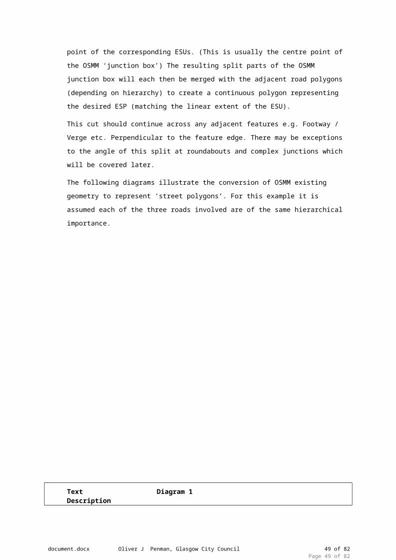
The following diagrams illustrate the conversion of OSMM existing geometry to represent ‘street
polygons’. For this example it is assumed each of the three roads involved are of the same
hierarchical importance.
document.docx Oliver J Penman, Glasgow City Council 39 of 64Page 39 of 64

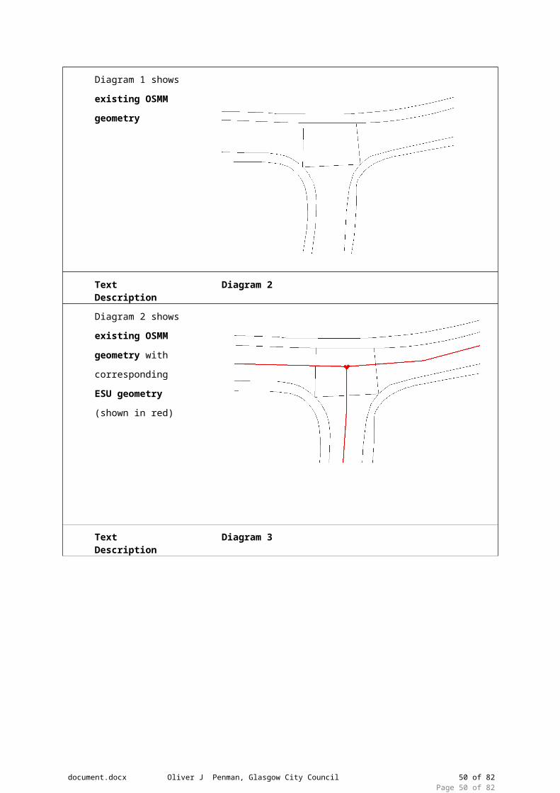
Text Description Diagram 1
Diagram 1 shows
existing OSMM geometry
Text Description Diagram 2
document.docx Oliver J Penman, Glasgow City Council 40 of 64Page 40 of 64

Diagram 2 shows
existing OSMM geometry with
corresponding ESU geometry (shown in
red)
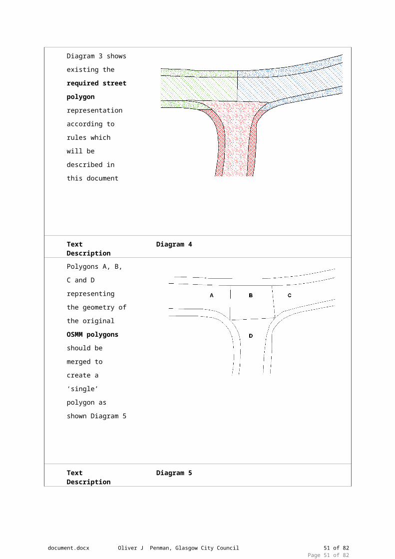
Text Description Diagram 3
Diagram 3 shows
existing the required street polygon
representation
according to rules
which will be
described in this
document
Text Description Diagram 4
Polygons A, B, C and
D representing the
geometry of the
original OSMM polygons should be
merged to create a
‘single’ polygon as
shown Diagram 5
document.docx Oliver J Penman, Glasgow City Council 41 of 64Page 41 of 64

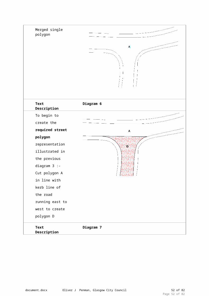
Text Description Diagram 5
Merged single polygon
Text Description Diagram 6
To begin to create
the required street polygon
representation
illustrated in the
previous diagram 3 :-
Cut polygon A in line
with kerb line of the
road running east to
west to create
polygon D
Text Description Diagram 7
Split polygon A by
drawing a line
perpendicular to the
split between A and
D which intersects
the junction of the
ESUs (shown in red)
and continues
through the northern
footway of A. This
will create road
polygons A and C
with corresponding
document.docx Oliver J Penman, Glasgow City Council 42 of 64Page 42 of 64

footways a and c.
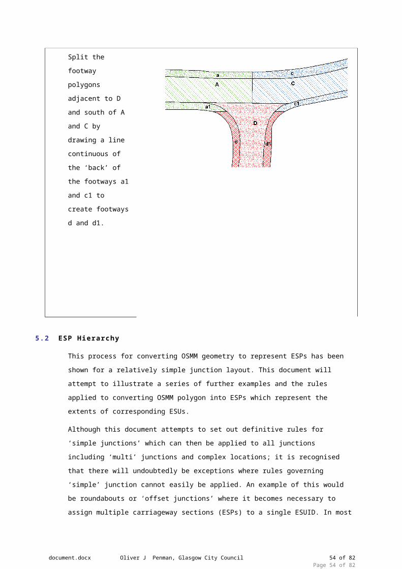
Text Description Diagram 8
Split the footway
polygons adjacent to
D and south of A and
C by drawing a line
continuous of the
‘back’ of the footways
a1 and c1 to create
footways d and d1.
5.2 ESP Hierarchy
This process for converting OSMM geometry to represent ESPs has been shown for a relatively
simple junction layout. This document will attempt to illustrate a series of further examples and
the rules applied to converting OSMM polygon into ESPs which represent the extents of
corresponding ESUs.
Although this document attempts to set out definitive rules for ‘simple junctions’ which can then
be applied to all junctions including ‘multi’ junctions and complex locations; it is recognised that
there will undoubtedly be exceptions where rules governing ‘simple’ junction cannot easily be
applied. An example of this would be roundabouts or ‘offset junctions’ where it becomes
necessary to assign multiple carriageway sections (ESPs) to a single ESUID. In most cases
specific ESPs will be assigned with the ESUID of the ESU which intersects or is contained by
that ESP. If it is decided that in specific circumstances an ESP contains or is intersected by
multiple ESUs then the ESP will be allocated the numerically lowest ESUID of these ESUs.
(Illustrated later within document)
document.docx Oliver J Penman, Glasgow City Council 43 of 64Page 43 of 64

The splitting of OSMM polygons to represent ESPs will be governed by a hierarchical order
where preference is given to the ‘higher rated’ carriageway and associated features. The order
in which prioritisation will be assigned is:-
Road Hierarchy
Classification
Local Knowledge
5.3 Junction Types
The following diagrammatical examples and corresponding text illustrate the method of splitting
OSMM polygons at road junctions based on the rules described in the previous paragraphs
Examples split into the following categories:-
Regular Junctions
Cross Roads
‘Offset’ Junctions (irregular junctions and junctions where roads meet at obtuse and
acute angles)
Roundabouts
Dual and Multi Carriageways
To elaborate the representation of ESU / ESP extents and geometry; each example will contain
two diagrams:
Diagram showing resultant street polygons after splitting / merging OSMM polygons with
ESUs shown in their linear form and extent with start / end points.
Diagram showing resultant street polygons after splitting / merging OSMM polygons only.
6. Junct ion Layouts
6.1 T Junctions
6.1.1 Simple T Junction
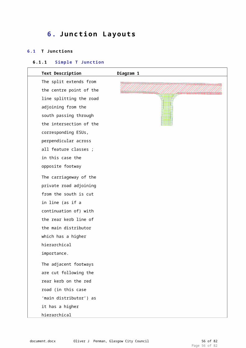
Text Description Diagram 1
The split extends from the
centre point of the line splitting
the road adjoining from the
south passing through the
intersection of the
corresponding ESUs,
perpendicular across all feature
classes ; in this case the
document.docx Oliver J Penman, Glasgow City Council 44 of 64Page 44 of 64

opposite footway
The carriageway of the private
road adjoining from the south is
cut in line (as if a continuation
of) with the rear kerb line of the
main distributor which has a
higher hierarchical importance.
The adjacent footways are cut
following the rear kerb on the
red road (in this case ‘main
distributor’) as it has a higher
hierarchical importance.
Legend Diagram 2 ESU geometry shown
Red RoadPublic
Main Distributor
A Class
Green RoadPrivate
Local Access
Unclassified
6.1.2 T Junction with Maintenance Split in Junction
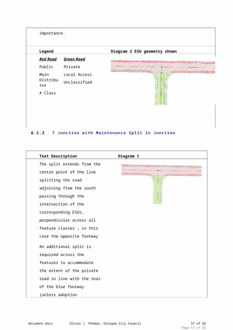
Text Description Diagram 1
The split extends from the centre
point of the line splitting the road
adjoining from the south passing
through the intersection of the
corresponding ESUs, perpendicular
across all feature classes ; in this
case the opposite footway
An additional split is required across
the features to accommodate the
extent of the private road in line with
document.docx Oliver J Penman, Glasgow City Council 45 of 64Page 45 of 64

the rear of the blue footway (unless
adoption documentation show the
extents as being elsewhere) across
the private road (green road)
passing through the intersection of
the corresponding ESUs.
The footway of the private road is
cut at the end of the public road, at
the start of the private section.
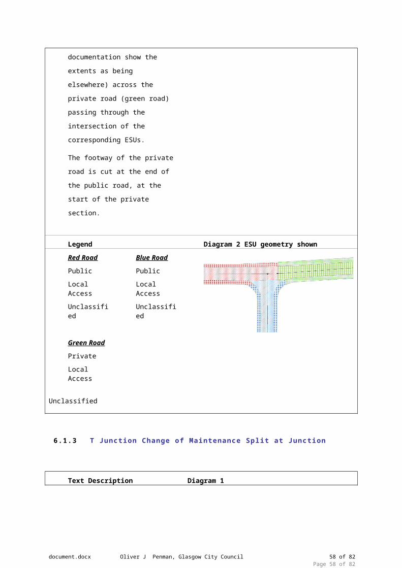
Legend Diagram 2 ESU geometry shown
Red RoadPublic
Local Access
Unclassified
Blue RoadPublic
Local Access
Unclassified
Green RoadPrivate
Local Access
Unclassified
6.1.3 T Junction Change of Maintenance Split at Junction
Text Description Diagram 1
The split extends from the centre
point of the line splitting the road
adjoining from the south passing
through the intersection of the
corresponding ESUs, perpendicular
across all feature classes ; in this
case the opposite footway
The carriageway of the adjoining
private road is cut in line with the
heel kerb across the private road as
in most cases there is maintenance
document.docx Oliver J Penman, Glasgow City Council 46 of 64Page 46 of 64

responsibility for the total footway
adjacent to the public road.
The footways are cut across the heel
kerbs on the public roads as they
have a greater hierarchical
importance than the private road.
Legend Diagram 2 ESU geometry shown
Red RoadPublic
Local Access
Unclassified
Blue RoadPublic
Local Access
Unclassified
Green RoadPrivate
Local Access
Unclassified
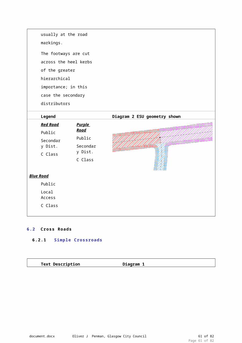
6.1.4 T Junction Displaying Hierarchy Geometry
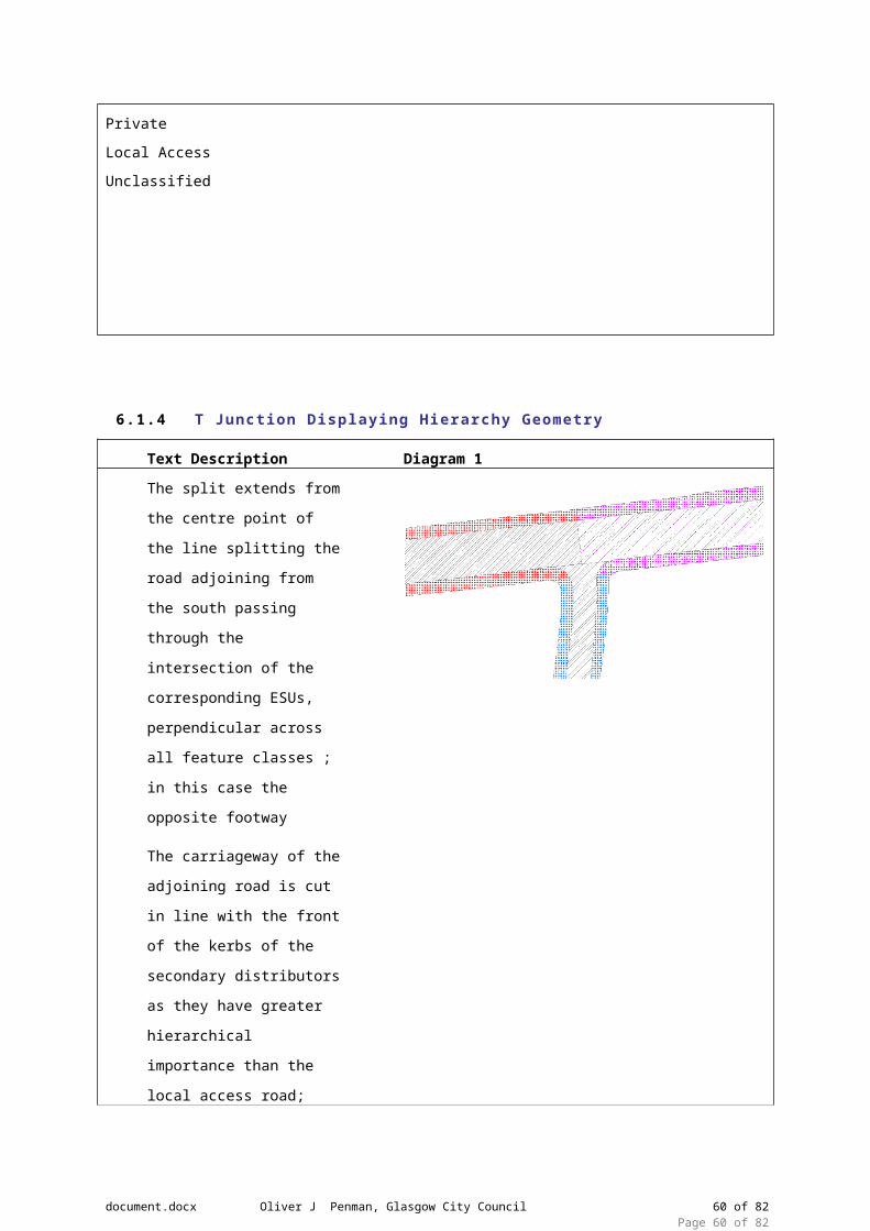
Text Description Diagram 1
The split extends from the
centre point of the line splitting
the road adjoining from the
south passing through the
intersection of the
corresponding ESUs,
perpendicular across all
feature classes ; in this case
the opposite footway
The carriageway of the
adjoining road is cut in line
with the front of the kerbs of
document.docx Oliver J Penman, Glasgow City Council 47 of 64Page 47 of 64

the secondary distributors as
they have greater hierarchical
importance than the local
access road; usually at the
road markings.
The footways are cut across
the heel kerbs of the greater
hierarchical importance; in this
case the secondary
distributors
Legend Diagram 2 ESU geometry shown
Red RoadPublic
Secondary Dist.
C Class
Purple RoadPublic
Secondary Dist.
C Class
Blue RoadPublic
Local Access
C Class
6.2 Cross Roads
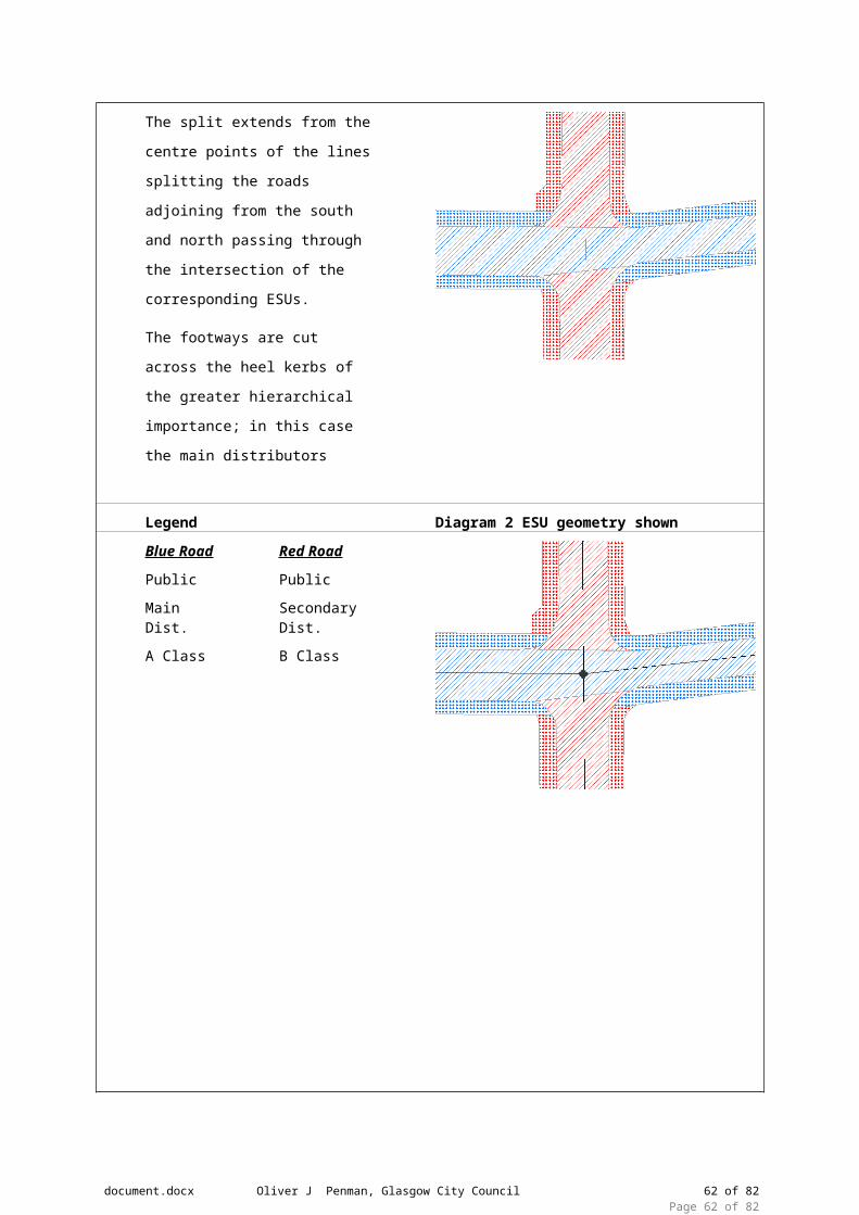
6.2.1 Simple Crossroads
Text Description Diagram 1
document.docx Oliver J Penman, Glasgow City Council 48 of 64Page 48 of 64
The split extends from the centre
points of the lines splitting the roads
adjoining from the south and north
passing through the intersection of
the corresponding ESUs.
The footways are cut across the
heel kerbs of the greater
hierarchical importance; in this case
the main distributors
Legend Diagram 2 ESU geometry shown
Blue RoadPublic
Main Dist.
A Class
Red RoadPublic
Secondary Dist.
B Class
6.2.2 Crossroads with Change of Maintenance Split at Junction
Text Description Diagram 1
document.docx Oliver J Penman, Glasgow City Council 49 of 64Page 49 of 64
The horizontal split extends from the
centre points of the lines splitting the
roads adjoining from the east and west
passing through the intersection of the
corresponding ESUs.
The vertical split between the
carriageway of the adjoining road from
the west is cut in line with the front of
the kerbs of the main distributors as
they have greater hierarchical
importance than the local access road;
usually at the road markings.
An additional split is required across the
features to accommodate the extent of
the private road perpendicular from the
intersection of the corresponding ESUs
of the private and public roads passing
through corresponding adjacent
features; in this case the north and
south footways representing the
adoption record.
Legend Diagram 2 ESU geometry shown
Blue RoadPublic
Local Access
Unclassified
Purple RoadPublic
Main Dist.
A Class
Green RoadPrivate
Local Access
Unclassified
Red RoadPublic
Main Dist.
B Class
document.docx Oliver J Penman, Glasgow City Council 50 of 64Page 50 of 64
6.3 Offset Junctions
6.3.1 Multi Offset Junction
Text Description Diagram 1
Offset junctions will be governed by the
same rules applied to the relatively simple
junctions covered in the previous
examples.
The junction between the purple and
black roads is treated as a T junction
between similar roads as is the junction of
the red and blue road.
The geometry of the corresponding ESU
of the black and blue roads coupled with
the split of the blue road resulting from
the junction with the red road creates
smaller polygon on the blue road.
The procedure to deal with this scenario
is highlighted below in diagram 2.29
The ‘irregular’ shaped footways / verges
are associated with adjacent blue road
Legend Diagram 2 ESU geometry shown
Blue RoadPublic
Local Access
B Class
Black RoadPublic
Local Access
C Class
Purple RoadPublic
Local Access
Unclassified
Red RoadPublic
Local Access
Unclassified
document.docx Oliver J Penman, Glasgow City Council 51 of 64Page 51 of 64
Situations such as that described in 2.29 will be treated as follows. Applying the rule of cutting
across a road perpendicularly from the centre point of the adjoining carriageway to the
intersection of the corresponding ESUs results in an additional polygon that doesn’t have a
unique ESU, i.e. the ESU relating to the blue polygon would have more than one polygon.
This illustrates well the situations that result in an ESU having many polygons associated with
it. This is more predominate with roundabouts.
In these instances the polygon should be associated with the ESU that enters the polygon from
the road it is associated with, i.e. it should be assigned to the ESU highlighted below as the
polygon is part of the blue road, and not the ESU coming from the north which relates to the
green road.
FIG 2.29
document.docx Oliver J Penman, Glasgow City Council 52 of 64Page 52 of 64

6.3.2 Offset Junction with Island
Text Description Diagram 1
The junction between the green and red
roads is treated as a T junction between
similar roads.
The intersection of blue and red roads is
treated by drawing a line continuous of
the northern kerb of the red road at the
intersections of blue roads either side of
the triangular island. Lines are then
drawn perpendicular to the split between
the blue roads and the red road starting
at the centre point of the split passing
through the intersection of the
corresponding ESUs to create ESPs on
the red road. This split will also cut any
adjacent features, in this case the south
footway of the red road, perpendicularly.
The split on the blue road approach to the
island from the north is created by
drawing a line perpendicular to either side
of the corresponding ESU also splitting
adjacent features perpendicularly.
The procedure for splitting the island is
explained below in diagram 2.29.1
Legend Diagram 2 ESU geometry shown
Blue RoadPublic
Local Access
Unclassified
Green RoadPrivate
Local Access
Unclassified
Red RoadPublic
Local Access
B Class
document.docx Oliver J Penman, Glasgow City Council 53 of 64Page 53 of 64
Using this method explained above and the rules governing the previous examples will result in the
necessity to divide islands into multiple sections enabling it to be accurately allocated to the relevant
road / ESUs. This ruling maintains the consistency of the convention to allow rules governing simple
junctions to be applied to any junction. In this example the island must be split into 3 parts each
assigned to 3 different ESUs. The southern part of the island is split using a line continuous of the
heel kerb of the footway associated with the red road due to its hierarchical importance. The
remainder of the island is split by creating a line from the midpoint of the line dividing the southern
footway to the apex of the island to the north. In the event that island is a more ‘irregular’ shape a line
would be drawn perpendicular from the midpoint of the line dividing the southern footway northwards
to split the remainder of the island in two.
This method will also be used to create polygons for central reserves. The central reserve will
be split along its geometrical centreline with each resultant half being allocated to the ESU on
the side it is located.
document.docx Oliver J Penman, Glasgow City Council 54 of 64Page 54 of 64
Fig. 2.29.1
6.3.3 Acute Angle Junction
Text Description Diagram 1
In the case where two roads meet at an
acute angle it is treated very similar to a T
junction between similar roads.
Where the green private road meets the
red public road is governed by the rules
of a typical T junction.
A split is between the blue road and the
red road from the heel kerb blue road,
due to its greater hierarchical importance,
following the curvature of the blue road
via the intersection of the corresponding
ESUs until it intersects with the kerb of
the red road. A further line is then drawn
from this ESU intersection perpendicular
with the red south footway intersecting
corresponding features.
The split on the blue road approach to the
junction from the west is created by
drawing a line perpendicular to either side
of the corresponding ESU also splitting
adjacent features perpendicularly.
Legend Diagram 2 ESU geometry shown
Blue RoadPublic
Strategic
A Class
Red RoadPublic
Secondary Dist
B Class
Green RoadPrivate
Local Access
Unclassified
document.docx Oliver J Penman, Glasgow City Council 55 of 64Page 55 of 64
6.4 Roundabouts
This is a draft document and therefore rules are subject to discussion. In the case of
roundabouts several options will be put forward for discussion prior to the document being
finalised.
6.4.1 Option 1
Option 1: Applying the general rule applied to T junctions and Crossroads fully to create
polygon geometry matching corresponding ESUs. This would result in following the line of the
corresponding ESUs of approach roads then continuing this split perpendicular to the ESU of
the roundabout and intersecting the central roundabout.
The general view is that although this option applies the rules of ‘simple’ junctions to a more
complicated situation it results in a very complicated solution which results in multiple polygons.
From a cartographic point of view this option is not ideal. The advantage of this solution is that
ESPs are unique to corresponding ESUs.
Text Description Diagram 1
Applying the general rule applied to T
junctions and Crossroads fully to create
polygon geometry matching corresponding
ESUs.
The approach roads are treated as T
junction involving dual carriageways as
discussed in previous examples with the
purple local access road being treated as a
normal T junction. The cut then continues
this split perpendicular to the ESU of the
roundabout and intersecting the central
roundabout Approach islands are also split
by applying previous rules.
The cut at these junctions are made using
a line parallel to the roundabout ESUs at
the kerb line of adjacent features and
islands.
Features adjacent to the roundabout are attached to the nearest ‘roundabout’ ESP.
document.docx Oliver J Penman, Glasgow City Council 56 of 64Page 56 of 64
Legend Diagram 2 ESU geometry shown
Blue & Red RoadPublic
Strategic
A Class
Purple RoadPublic
Local Access
Unclassified
Black RoadPublic
Local Access
C Class
Green RoadPrivate
Local Access
Unclassified
6.4.2 Option 2
Applying the general rule applied to T junctions and Crossroads to create polygon geometry matching
corresponding ESUs is applied. Although in this case an exception is made to allow the split in the
inner ring of the roundabout to be created by a line perpendicular to the ‘roundabout’ ESU. Also the
central feature of the roundabout is attributed to the lowest numbered ESU of the roundabout.
The general view is that although this option does not adhere strictly to the general rules
governing simple junctions it creates a simpler and more manageable solution. From a
cartographic point of view this option is more pleasing.
Text Description Diagram 1
In this option the approach roads are
treated as T junction involving dual
carriageways as discussed in previous
examples with the purple local access
road being treated as a normal T
junction. Approach islands are also
split by applying previous rules.
The main difference from Option 1 is
that the cut across the roundabout id
drawn perpendicular to the
‘roundabout’ ESUs as opposed to
document.docx Oliver J Penman, Glasgow City Council 57 of 64Page 57 of 64
following the line of the approaching
ESUs on the outer ring of the
roundabout.
In this example the central feature of
the roundabout is attributed to the
lowest numbered ESU of the
roundabout.
Approach islands are also split by
applying previous rules.
The cut at these junctions are made
using a line parallel to the roundabout
ESUs at the kerb line of adjacent
features and islands.
Features adjacent to the roundabout
are attached to the nearest
‘roundabout’ ESP.
Legend Diagram 2 ESU geometry shown
Blue & Red RoadPublic
Strategic
A Class
Purple RoadPublic
Local Access
Unclassified
Black RoadPublic
Local Access
C Class
Green RoadPrivate
Local Access
Unclassified
document.docx Oliver J Penman, Glasgow City Council 58 of 64Page 58 of 64

6.4.3 Option 3
Option 3 The general rule applied to T junctions and Crossroads to create polygon geometry
matching corresponding ESUs is not fully applied. In this option a line is drawn perpendicular
from the point where the ESU of the approach roads intersect with the split between these
roads and the roundabout. This result is that not all ESUs having a corresponding ESPs.
The general view is that although this option does not adhere strictly to the general rules
governing simple junctions it creates a simpler and more manageable solution than option 1.
From a cartographic point of view this option is the most pleasing. The disadvantage is that not
all ESUs having a corresponding ESPs. This solution may involve amending present ESU
geometry to match ESP geometry which is not in the scope of this convention.
Text Description Diagram 1
In this option the general rule applied to T
junctions and Crossroads to create
polygon geometry matching
corresponding ESUs is not fully applied.
In this option a line is drawn
perpendicular from the point where the
ESU of the approach roads intersect with
the split between these roads and the
roundabout. This result is that not all
ESUs having a corresponding ESPs
T junction involving dual carriageways
treated as discussed in previous
examples with the purple local access
road being treated as a normal T junction.
Approach islands are also split by
applying previous rules.
The main difference from Option 2 is that
there is cut across the roundabout where
the continuous curve of approach ESUs
meet the roundabout ESUs.
In this example the central feature of the
roundabout is attributed to the lowest
document.docx Oliver J Penman, Glasgow City Council 59 of 64Page 59 of 64
numbered ESU of the roundabout.
Approach islands are also split by
applying previous rules.
The cut at these junctions are made using
a line parallel to the roundabout ESUs at
the kerb line of adjacent features and
islands.
Features adjacent to the roundabout are
attached to the nearest ‘roundabout’ ESP.
Legend Diagram 2 ESU geometry shown
Blue & Red RoadPublic
Strategic
A Class
Purple RoadPublic
Local Access
Unclassified
Black RoadPublic
Local Access
C Class
Green RoadPrivate
Local Access
Unclassified
There may be another viable option where the constituent ESU making up the roundabout are
represented by one continuous polygon.
document.docx Oliver J Penman, Glasgow City Council 60 of 64Page 60 of 64
6.4.4 Roundabout ESU Assignment
The proposal (Option 3) would result in the polygonisation shown below in Fig. 2.29.4. Note: the
roundabout is elevated and has a dual carriage running below. Also the maintenance
responsibility for the verge to the east and west of the roundabout change just before the
junction creating a narrow strip.
This scenario results in areas created between junctions on the roundabout that don’t have
their own unique ESUs i.e. They are shared by and intersected by the geometry of more than
one ESU. These areas can be seen highlighted in blue in Fig. 2.29.4.1. Such areas should be
assigned to the ESU of the road they of which they are a constituent part of (in this case red
road roundabout). Due to the fact it is a roundabout, there could be one of two ESUs to choose
from, and in this case the lowest numbered ESU should be selected.
The verge within this roundabout, between slips could be assigned to either the roundabout or
the carriageway going over / under the roundabout. This would be user preference as it may be
document.docx Oliver J Penman, Glasgow City Council 61 of 64Page 61 of 64
Fig. 2.29.4
Fig. 2.29.4.1
best to allocate to the road they are maintained from etc.
6.5 Dual Carriageway Cross Overs
Centre reserves have to be split down the middles as well so that each side can be assigned to
the neighbouring ESU ID
6.5.1 Option 1 (Cross Over Acceleration / Decelerat ion lanes separate entit ies)
It is necessary to discuss these scenarios further with Transport Scotland before a decision is
made as this will generally only affect trunk roads.
Text Description Diagram 1
Legend Diagram 2 ESU geometry shown
document.docx Oliver J Penman, Glasgow City Council 62 of 64Page 62 of 64
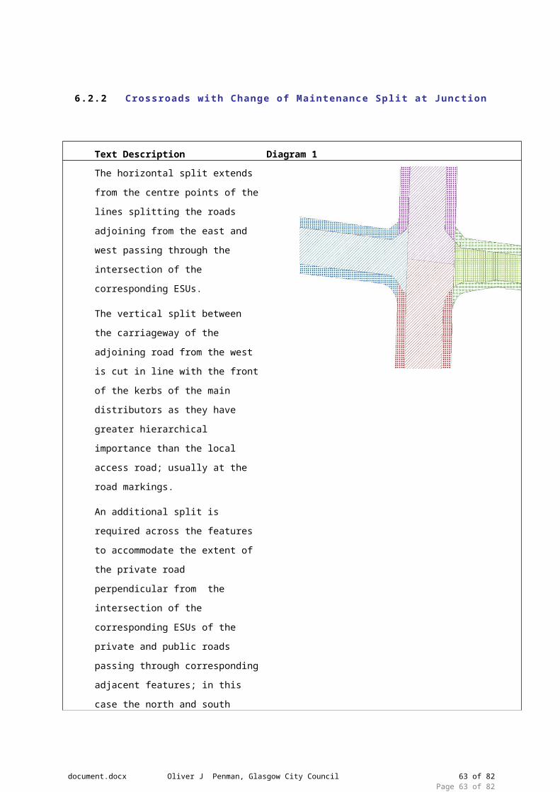
Blue & Red RoadPublic
TRUNK
A Class
Purple RoadPublic
Local Access
A Class
The acceleration / deceleration lanes at the junction side of the main carriageway will be
separated to create a separate polygon as they have their own ESUs and consequently ESP’s.
Some questions to be answered by Transport Scotland:-
What do you do with the acceleration and deceleration lanes that are in the middle as part of
the cross over element?
Assign it all to the ESU that crosses the junction?
If you do that how much of the deceleration lanes to you include with the middle section? All or
should some be part of the main carriageway?
6.5.2 Option 2(Cross Over Acceleration / Decelerat ion lanes part of main carriageway)
Text Description Diagram 1
document.docx Oliver J Penman, Glasgow City Council 63 of 64Page 63 of 64
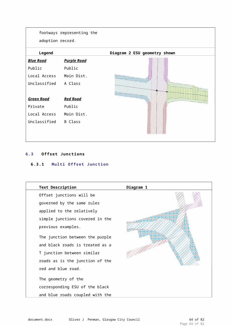
Legend Diagram 2 ESU geometry shown
Blue & Red RoadPublic
TRUNK
A Class
Green RoadPublic
Local Access
A Class
document.docx Oliver J Penman, Glasgow City Council 64 of 64Page 64 of 64