Embed Size (px)
Citation preview
SCORGTM V5.4, 2016
© PDM Analysis Ltd, 2016 Page | 1
TM
SCORGTM Setup for CFD Simulation of
Twin Screw Machines with STAR-CCM+®
SCORGTM is the CFD grid generation tool for rotary twin screw machines. The tool includes
additional modules for designing and editing rotor profiles, executing a thermodynamic
calculation based on quasi 1D chamber models and generating the deforming working chamber
grids for selected commercial CFD solvers.
For more information on the product please visit the website: www.pdmanalysis.co.uk or refer
to documentation help.
This guide lists the steps for setting up a CFD simulation for Twin Screw Compressor with
SCORGTM and STAR-CCM+ Solver. The user is expected to be familiar with screw machines,
CFD and STAR-CCM+ in order to be able to use these procedures. It is highly recommended
that books on that topic are studied12
The setup steps here are demonstrated for Windows 7, x64 bit OS. Refer SCORGTM Installation
Guide V5.4 for system and hardware requirements.
Table of Contents 1 Introduction ........................................................................................................................ 2
2 SCORGTM Project .............................................................................................................. 3
3 SCORGTM Mesh Generation............................................................................................ 10
4 Compile User defined Library [ One time procedure ].................................................... 21
5 STAR-CCM+ case setup ................................................................................................. 24
6 STAR-CCM+ Solver Calculation .................................................................................... 44
7 Summary .......................................................................................................................... 51
8 Bibliography .................................................................................................................... 51
1 N. Stosic, I.K. Smith, A. Kovacevic Screw Compressor Mathematical Modelling and Performance Calculation, Springer,
UK 2005, ISBN-10 3-540-24275-9 2 A. Kovacevic. N. Stosic, I.K. Smith, Screw Compressor Three Dimensional Computational Fluid Dynamics and Fluid
Solid Interaction, Springer, 2006, ISBN 3-540-36302-5
SCORGTM V5.4, 2016
© PDM Analysis Ltd, 2016 Page | 2
TM
1 Introduction
Screw Compressors are rotary positive displacement machines. Although the working principle
of these machines is simple, the geometry of rotors which are in the form of multi -lobe helical
screws meshing with each other, is making analysis by use of Computational Fluid Dynamics
(CFD) challenging. The process starts when the lobes are engaged at one end, which creates
continuous increase of the volume between the rotors and the casing which reduces pressure in
the suction domain and draws the working fluid in. Further rotation of the rotors makes this
volume between the rotors and the casing enclosed when the compression of fluid begins. This
increases the pressure within the chamber. Further rotation exposes the pressurized fluid to the
outlet port and the fluid is delivered (Stosic, et al., 2005). Similar process is occurring in other
helical screw machines such as pumps, vacuum pumps, gear pumps, expanders, extruders and
motors. The CFD is equally challenging in such machines due to sliding and stretching
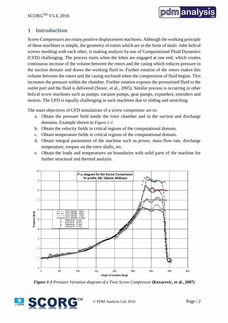
The main objectives of CFD simulations of a screw compressor are to:
a. Obtain the pressure field inside the rotor chamber and in the suction and discharge
domains. Example shown in Figure 1-1.
b. Obtain the velocity fields in critical regions of the computational domain.
c. Obtain temperature fields in critical regions of the computational domain.
d. Obtain integral parameters of the machine such as power, mass flow rate, discharge
temperature, torques on the rotor shafts, etc.
e. Obtain the loads and temperatures on boundaries with solid parts of the machine for
further structural and thermal analysis.
Figure 1-1 Pressure Variation diagram of a Twin Screw Compressor (Kovacevic, et al., 2007)
SCORGTM V5.4, 2016
© PDM Analysis Ltd, 2016 Page | 3
TM
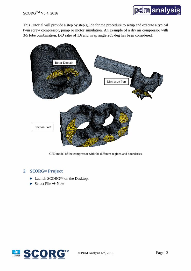
This Tutorial will provide a step by step guide for the procedure to setup and execute a typical
twin screw compressor, pump or motor simulation. An example of a dry air compressor with
3/5 lobe combination, L/D ratio of 1.6 and wrap angle 285 deg has been considered.
CFD model of the compressor with the different regions and boundaries
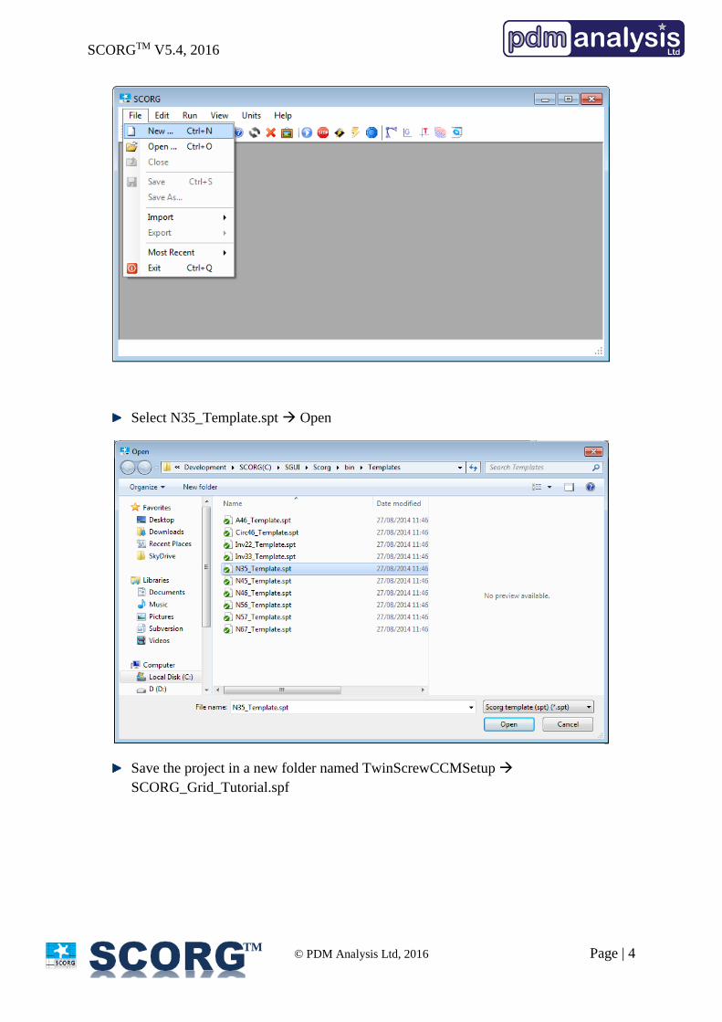
2 SCORGTM Project
Launch SCORGTM on the Desktop.
Select File New
Suction Port
Discharge Port
Rotor Domain
SCORGTM V5.4, 2016
© PDM Analysis Ltd, 2016 Page | 4
TM
Select N35_Template.spt Open
Save the project in a new folder named TwinScrewCCMSetup
SCORG_Grid_Tutorial.spf
SCORGTM V5.4, 2016
© PDM Analysis Ltd, 2016 Page | 5
TM
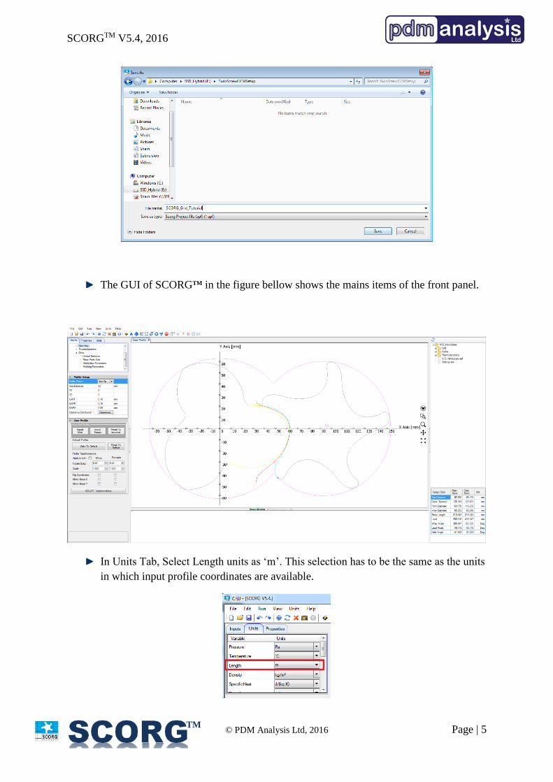
The GUI of SCORGTM in the figure bellow shows the mains items of the front panel.
In Units Tab, Select Length units as ‘m’. This selection has to be the same as the units
in which input profile coordinates are available.
SCORGTM V5.4, 2016
© PDM Analysis Ltd, 2016 Page | 6
TM
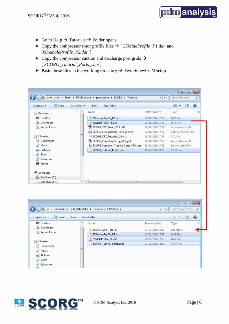
Go to Help Tutorials Folder opens
Copy the compressor rotor profile files [ 35MaleProfile_P1.dat and
35FemaleProfile_P2.dat ]
Copy the compressor suction and discharge port grids
[ SCORG_Tutorial_Ports_.sim ]
Paste these files in the working directory TwinScrewCCMSetup
SCORGTM V5.4, 2016
© PDM Analysis Ltd, 2016 Page | 7
TM
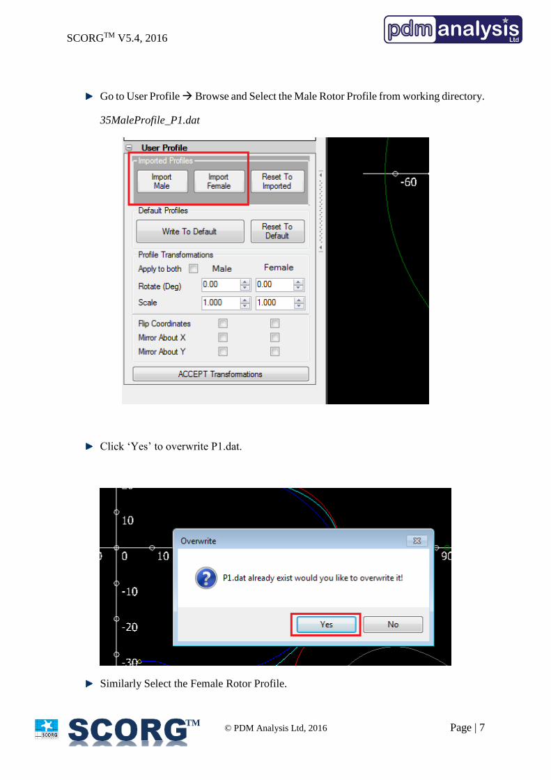
Go to User Profile Browse and Select the Male Rotor Profile from working directory.
35MaleProfile_P1.dat
Click ‘Yes’ to overwrite P1.dat.
Similarly Select the Female Rotor Profile.
SCORGTM V5.4, 2016
© PDM Analysis Ltd, 2016 Page | 8
TM
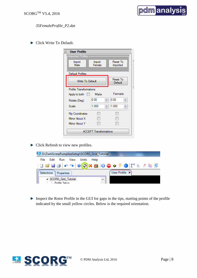
35FemaleProfile_P2.dat
Click Write To Default.
Click Refresh to view new profiles.
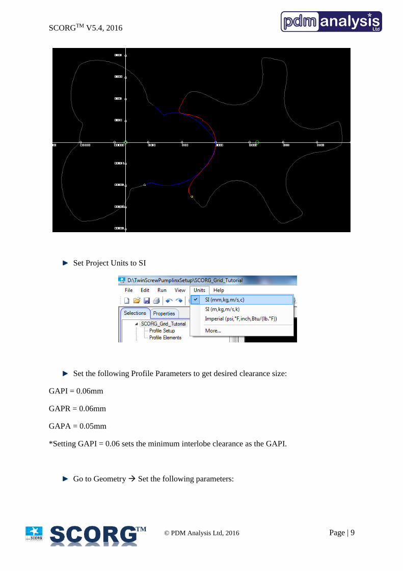
Inspect the Rotor Profile in the GUI for gaps in the tips, starting points of the profile
indicated by the small yellow circles. Below is the required orientation.
SCORGTM V5.4, 2016
© PDM Analysis Ltd, 2016 Page | 9
TM
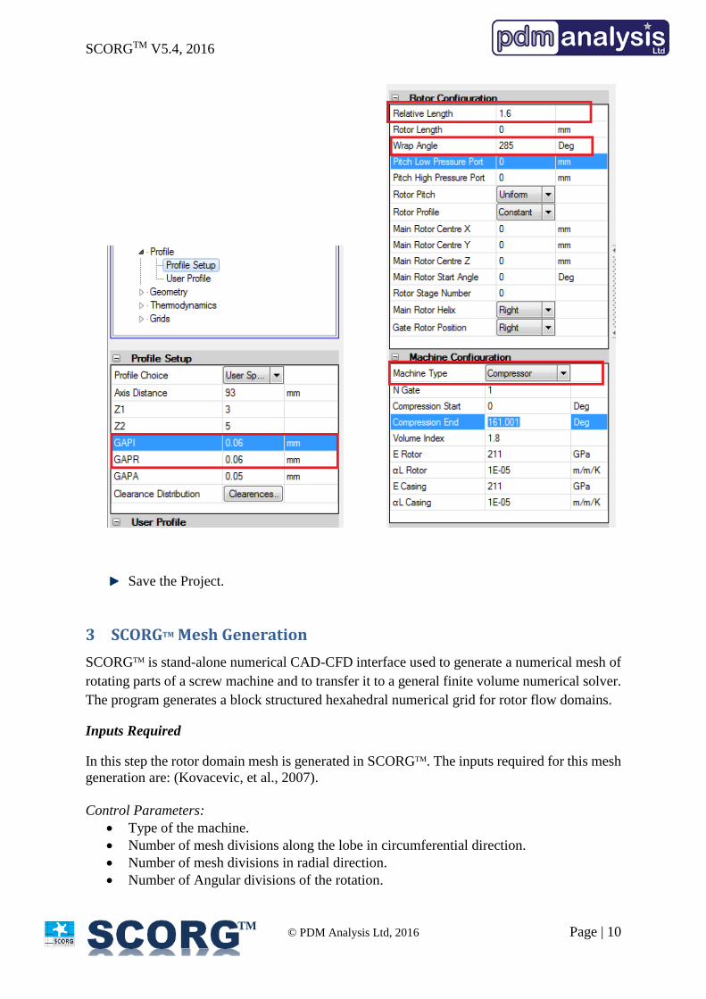
Set Project Units to SI
Set the following Profile Parameters to get desired clearance size:
GAPI = 0.06mm
GAPR = 0.06mm
GAPA = 0.05mm
*Setting GAPI = 0.06 sets the minimum interlobe clearance as the GAPI.
Go to Geometry Set the following parameters:
SCORGTM V5.4, 2016
© PDM Analysis Ltd, 2016 Page | 10
TM
Save the Project.
3 SCORGTM Mesh Generation
SCORGTM is stand-alone numerical CAD-CFD interface used to generate a numerical mesh of
rotating parts of a screw machine and to transfer it to a general finite volume numerical solver.
The program generates a block structured hexahedral numerical grid for rotor flow domains.
Inputs Required
In this step the rotor domain mesh is generated in SCORGTM. The inputs required for this mesh
generation are: (Kovacevic, et al., 2007).
Control Parameters:
Type of the machine.
Number of mesh divisions along the lobe in circumferential direction.
Number of mesh divisions in radial direction.
Number of Angular divisions of the rotation.
SCORGTM V5.4, 2016
© PDM Analysis Ltd, 2016 Page | 11
TM
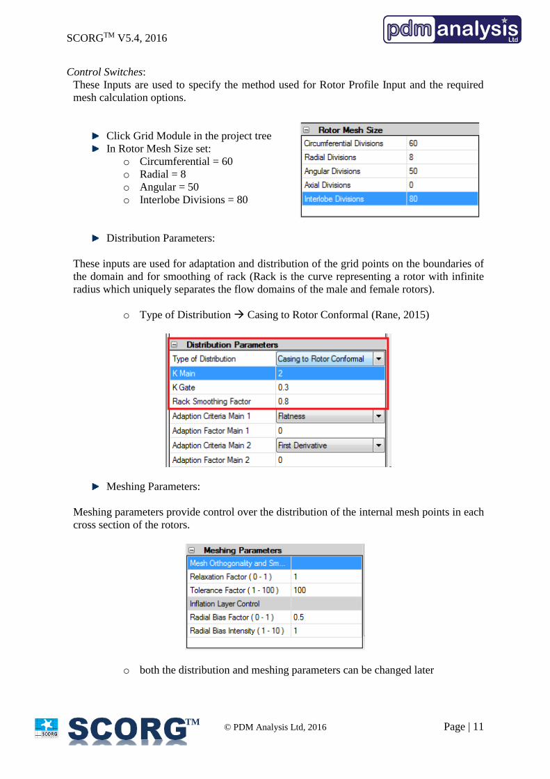
Control Switches:
These Inputs are used to specify the method used for Rotor Profile Input and the required
mesh calculation options.
Click Grid Module in the project tree
In Rotor Mesh Size set:
o Circumferential = 60
o Radial = 8
o Angular = 50
o Interlobe Divisions = 80
Distribution Parameters:
These inputs are used for adaptation and distribution of the grid points on the boundaries of
the domain and for smoothing of rack (Rack is the curve representing a rotor with infinite
radius which uniquely separates the flow domains of the male and female rotors).
o Type of Distribution Casing to Rotor Conformal (Rane, 2015)
Meshing Parameters:
Meshing parameters provide control over the distribution of the internal mesh points in each
cross section of the rotors.
o both the distribution and meshing parameters can be changed later
SCORGTM V5.4, 2016
© PDM Analysis Ltd, 2016 Page | 12
TM
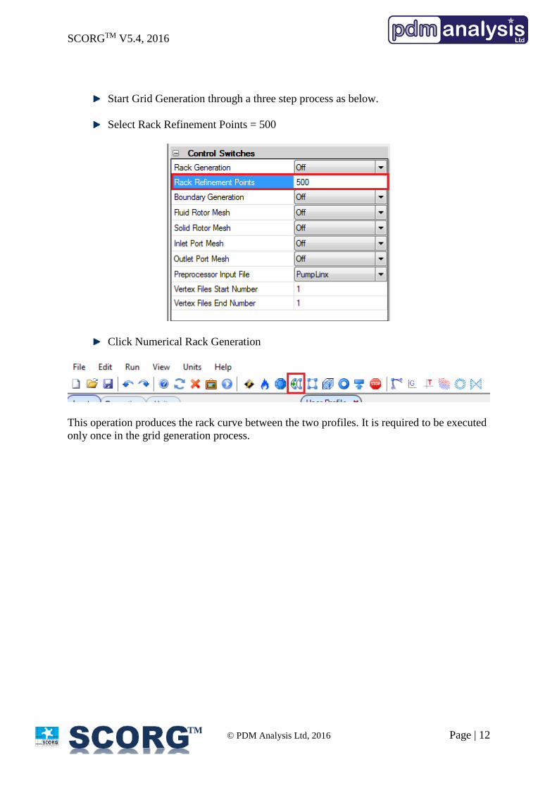
Start Grid Generation through a three step process as below.
Select Rack Refinement Points = 500
Click Numerical Rack Generation
This operation produces the rack curve between the two profiles. It is required to be executed
only once in the grid generation process.
SCORGTM V5.4, 2016
© PDM Analysis Ltd, 2016 Page | 13
TM
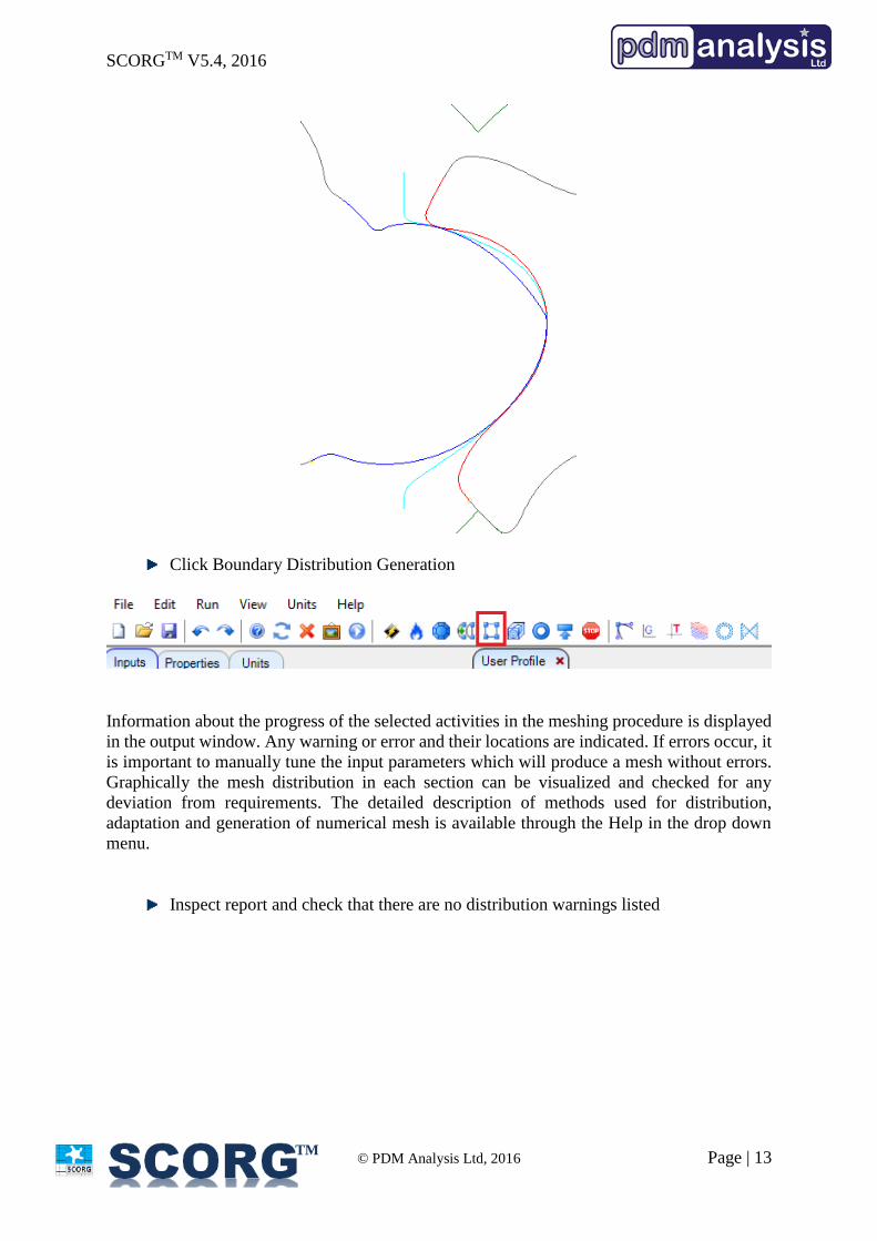
Click Boundary Distribution Generation
Information about the progress of the selected activities in the meshing procedure is displayed
in the output window. Any warning or error and their locations are indicated. If errors occur, it
is important to manually tune the input parameters which will produce a mesh without errors.
Graphically the mesh distribution in each section can be visualized and checked for any
deviation from requirements. The detailed description of methods used for distribution,
adaptation and generation of numerical mesh is available through the Help in the drop down
menu.
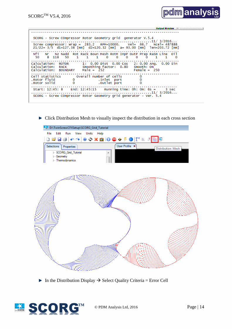
Inspect report and check that there are no distribution warnings listed
SCORGTM V5.4, 2016
© PDM Analysis Ltd, 2016 Page | 14
TM
Click Distribution Mesh to visually inspect the distribution in each cross section
In the Distribution Display Select Quality Criteria = Error Cell
SCORGTM V5.4, 2016
© PDM Analysis Ltd, 2016 Page | 15
TM
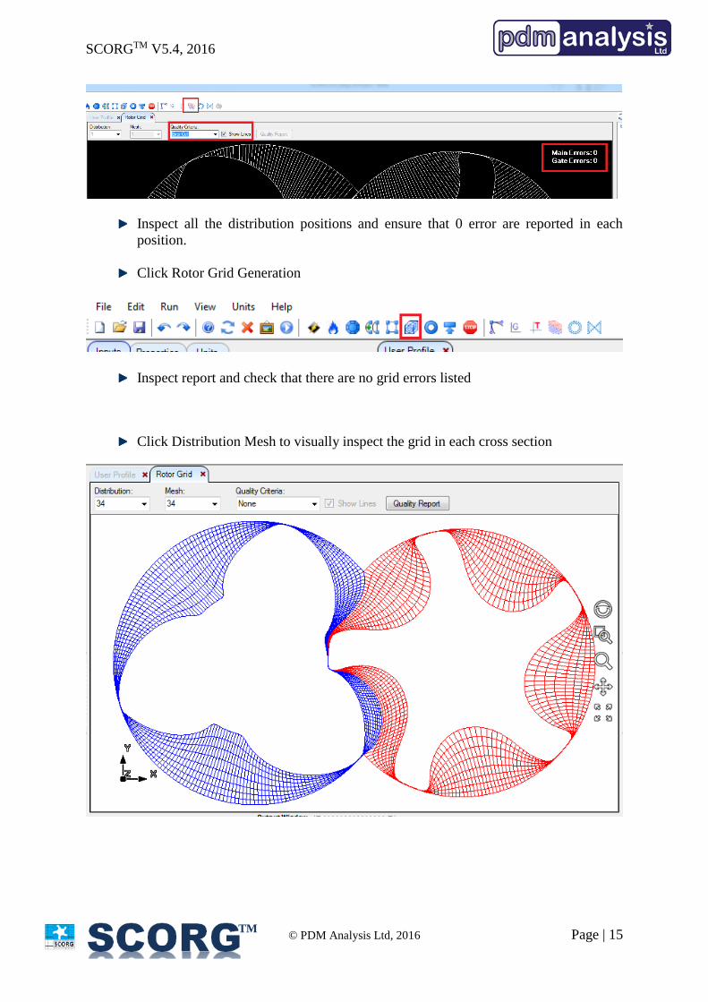
Inspect all the distribution positions and ensure that 0 error are reported in each
position.
Click Rotor Grid Generation
Inspect report and check that there are no grid errors listed
Click Distribution Mesh to visually inspect the grid in each cross section
SCORGTM V5.4, 2016
© PDM Analysis Ltd, 2016 Page | 16
TM
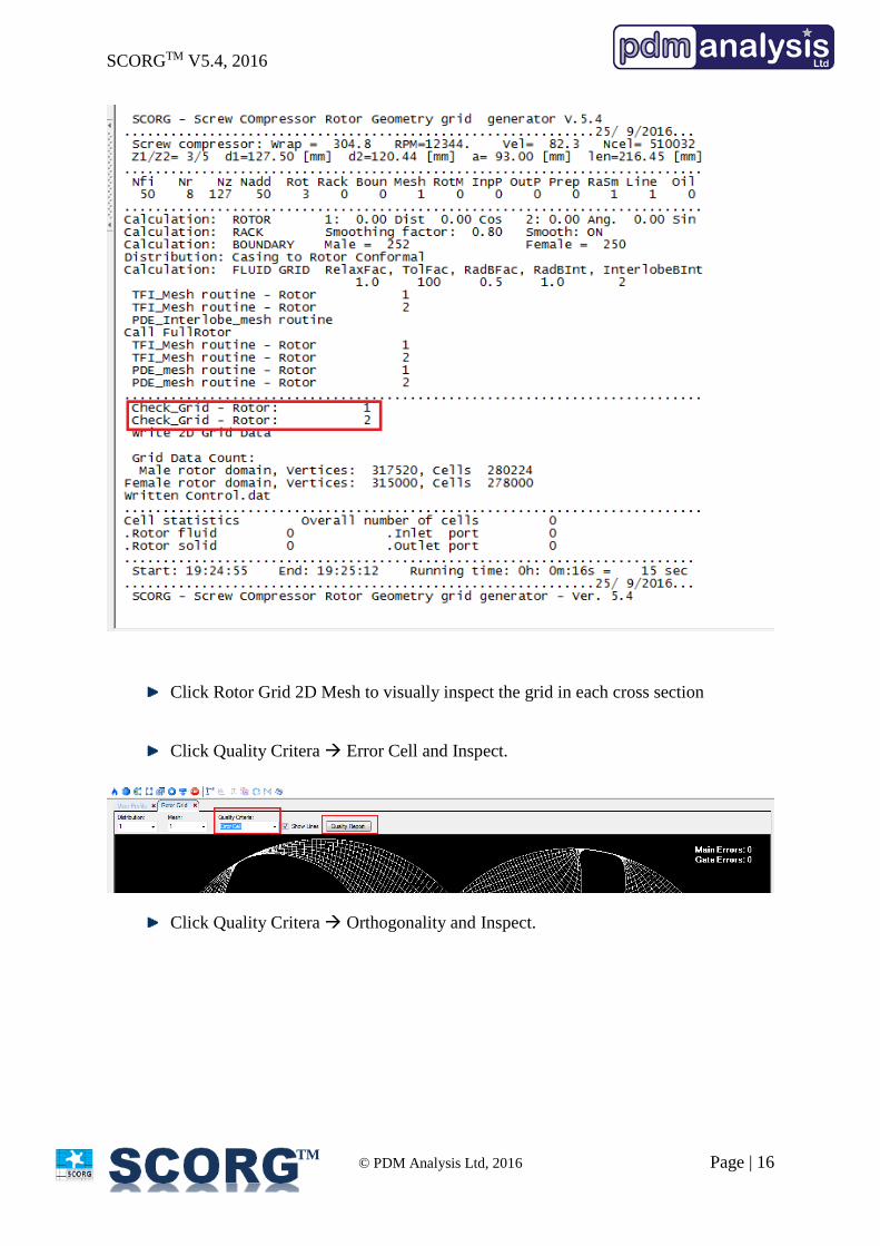
Click Rotor Grid 2D Mesh to visually inspect the grid in each cross section
Click Quality Critera Error Cell and Inspect.
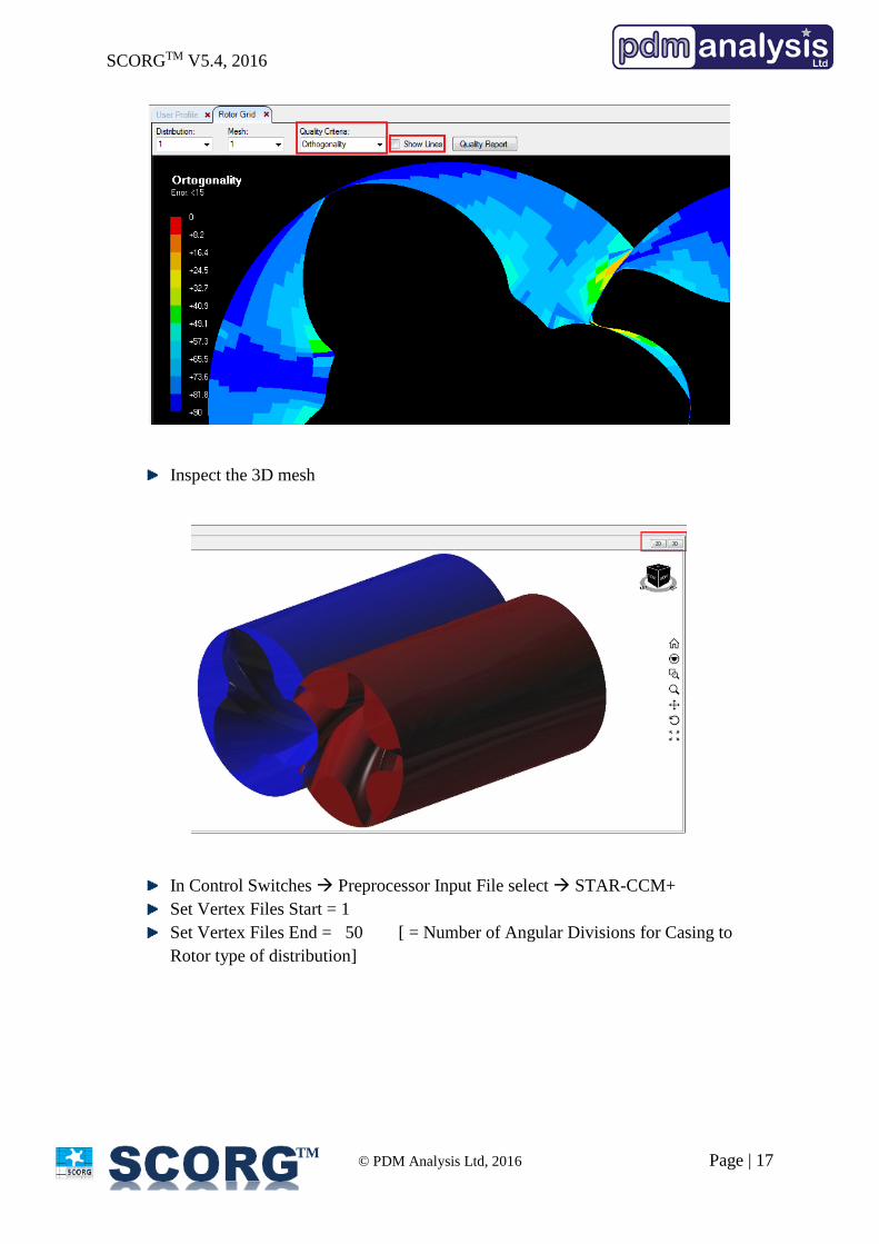
Click Quality Critera Orthogonality and Inspect.
SCORGTM V5.4, 2016
© PDM Analysis Ltd, 2016 Page | 17
TM
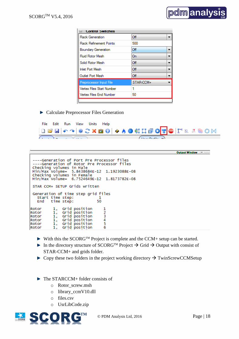
Inspect the 3D mesh
In Control Switches Preprocessor Input File select STAR-CCM+
Set Vertex Files Start = 1
Set Vertex Files End = 50 [ = Number of Angular Divisions for Casing to
Rotor type of distribution]
SCORGTM V5.4, 2016
© PDM Analysis Ltd, 2016 Page | 18
TM
Calculate Preprocessor Files Generation
With this the SCORGTM Project is complete and the CCM+ setup can be started.
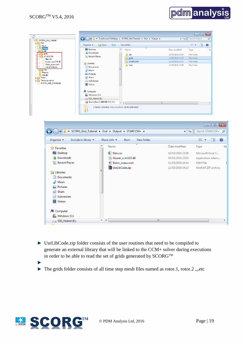
In the directory structure of SCORGTM Project Grid Output with consist of
STAR-CCM+ and grids folder.
Copy these two folders in the project working directory TwinScrewCCMSetup
The STARCCM+ folder consists of
o Rotor_screw.msh
o library_ccmV10.dll
o files.csv
o UsrLibCode.zip
SCORGTM V5.4, 2016
© PDM Analysis Ltd, 2016 Page | 19
TM
UsrLibCode.zip folder consists of the user routines that need to be compiled to
generate an external library that will be linked to the CCM+ solver during executions
in order to be able to read the set of grids generated by SCORGTM
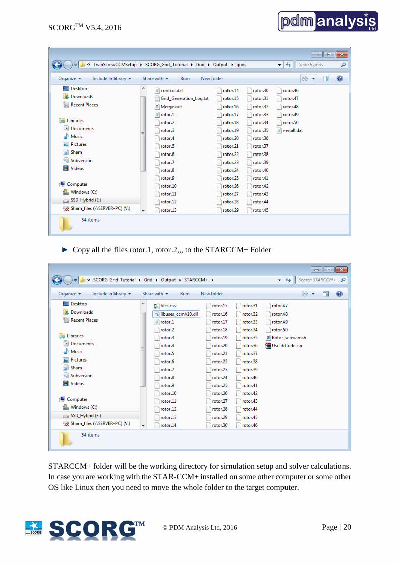
The grids folder consists of all time step mesh files named as rotor.1, rotor.2 ,,,etc
SCORGTM V5.4, 2016
© PDM Analysis Ltd, 2016 Page | 20
TM
Copy all the files rotor.1, rotor.2,,, to the STARCCM+ Folder
STARCCM+ folder will be the working directory for simulation setup and solver calculations.
In case you are working with the STAR-CCM+ installed on some other computer or some other
OS like Linux then you need to move the whole folder to the target computer.

SCORGTM V5.4, 2016
© PDM Analysis Ltd, 2016 Page | 21
TM
4 Compile User defined Library [ One time procedure ]
C++ Compiler is required to build the user library required for the setup. It is not required to
repeat this step for every CCM+ case setup.
For Windows OS,
Install Microsoft Visual Studio 2015 or any later version with C++ x64 bit libraries.
Below are some links that provide these installers, but if you have other C++ compiler then it
can be used.
https://www.visualstudio.com/en-us/products/visual-studio-community-vs.aspx
You can then access the compiler command prompt as shown below. Try to run cl command
to check if it is recognized and properly works.
SCORGTM V5.4, 2016
© PDM Analysis Ltd, 2016 Page | 22
TM
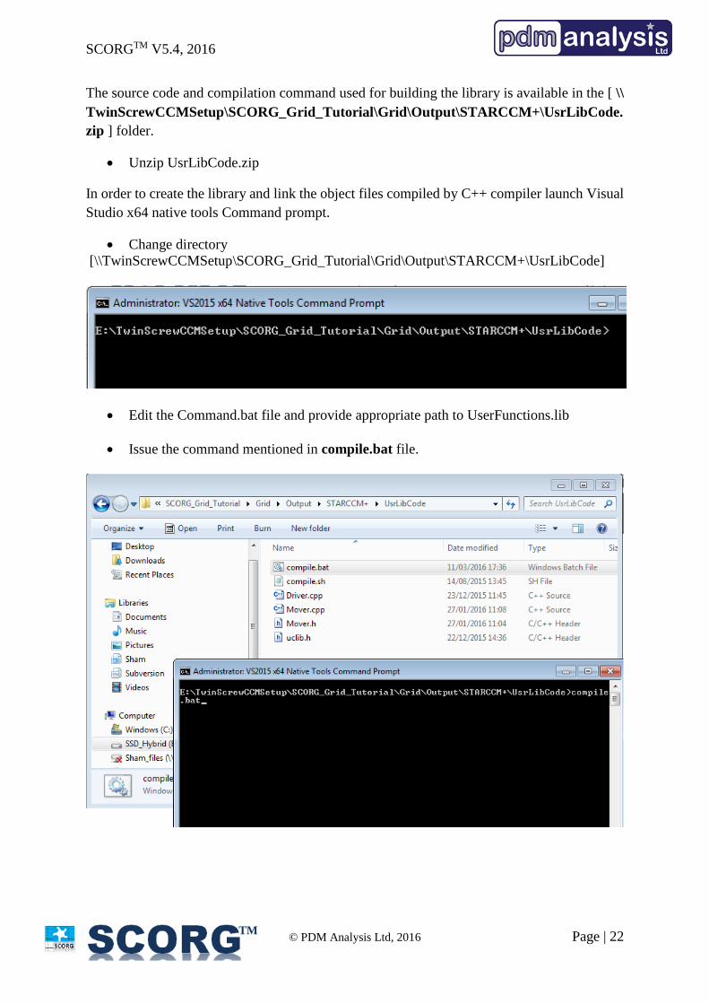
The source code and compilation command used for building the library is available in the [ \\
TwinScrewCCMSetup\SCORG_Grid_Tutorial\Grid\Output\STARCCM+\UsrLibCode.
zip ] folder.
Unzip UsrLibCode.zip
In order to create the library and link the object files compiled by C++ compiler launch Visual
Studio x64 native tools Command prompt.
Change directory
[\\TwinScrewCCMSetup\SCORG_Grid_Tutorial\Grid\Output\STARCCM+\UsrLibCode]
Edit the Command.bat file and provide appropriate path to UserFunctions.lib
Issue the command mentioned in compile.bat file.
SCORGTM V5.4, 2016
© PDM Analysis Ltd, 2016 Page | 23
TM
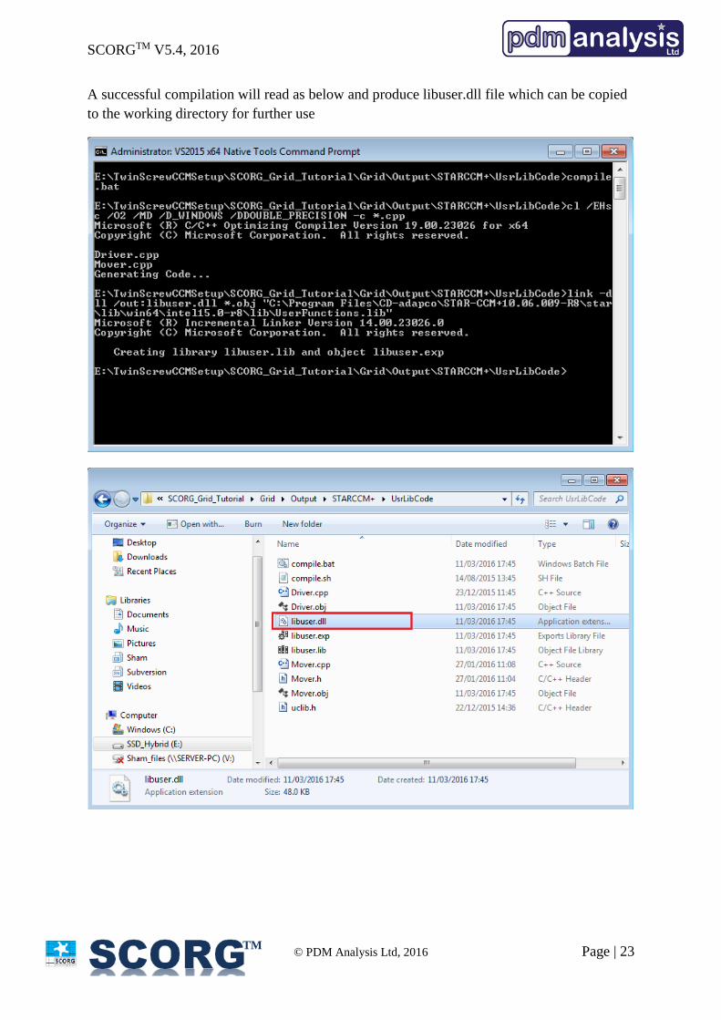
A successful compilation will read as below and produce libuser.dll file which can be copied
to the working directory for further use
SCORGTM V5.4, 2016
© PDM Analysis Ltd, 2016 Page | 24
TM
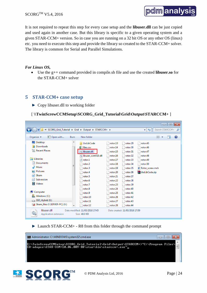
It is not required to repeat this step for every case setup and the libuser.dll can be just copied
and used again in another case. But this library is specific to a given operating system and a
given STAR-CCM+ version. So in case you are running on a 32 bit OS or any other OS (linux)
etc. you need to execute this step and provide the library so created to the STAR-CCM+ solver.
The library is common for Serial and Parallel Simulations.
For Linux OS,
Use the g++ command provided in compile.sh file and use the created libuser.so for
the STAR-CCM+ solver
5 STAR-CCM+ case setup
Copy libuser.dll to working folder
[ \\TwinScrewCCMSetup\SCORG_Grid_Tutorial\Grid\Output\STARCCM+ ]
Launch STAR-CCM+ - R8 from this folder through the command prompt
SCORGTM V5.4, 2016
© PDM Analysis Ltd, 2016 Page | 25
TM
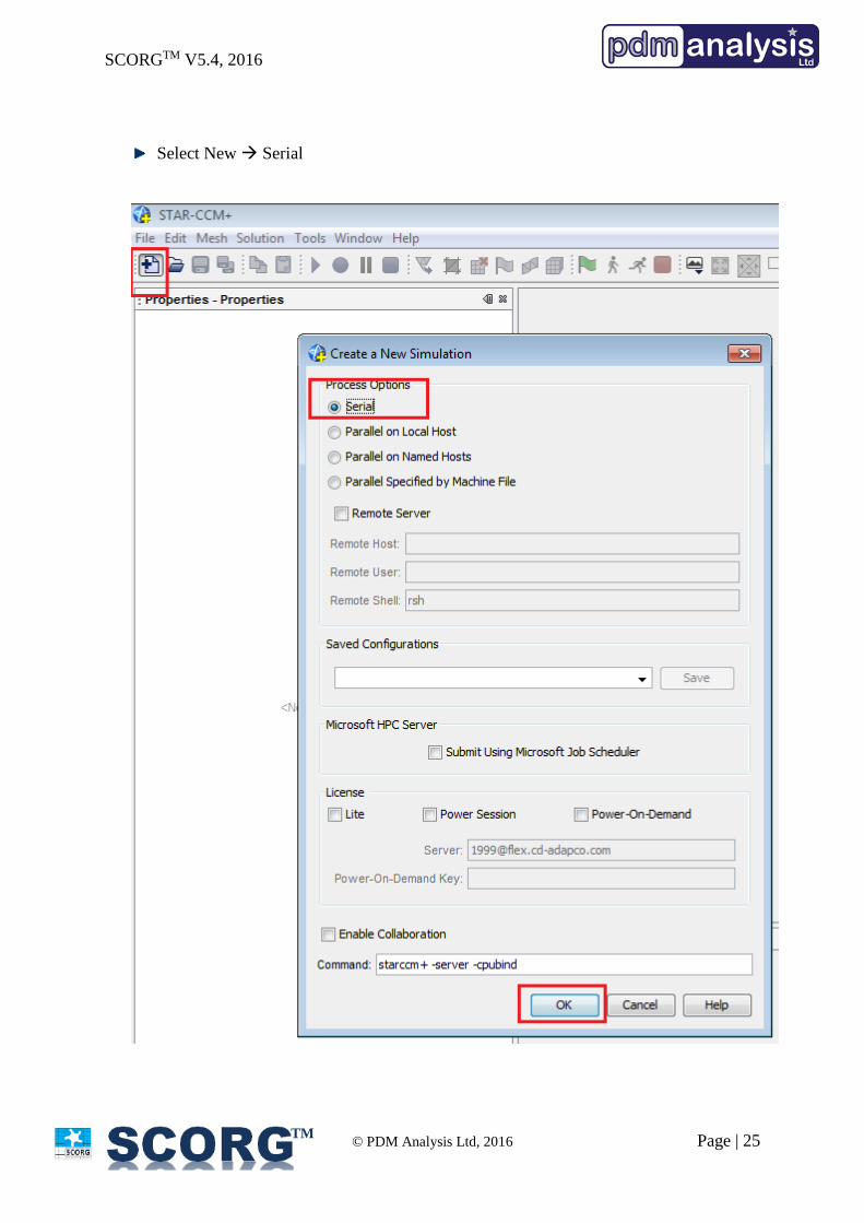
Select New Serial
SCORGTM V5.4, 2016
© PDM Analysis Ltd, 2016 Page | 26
TM
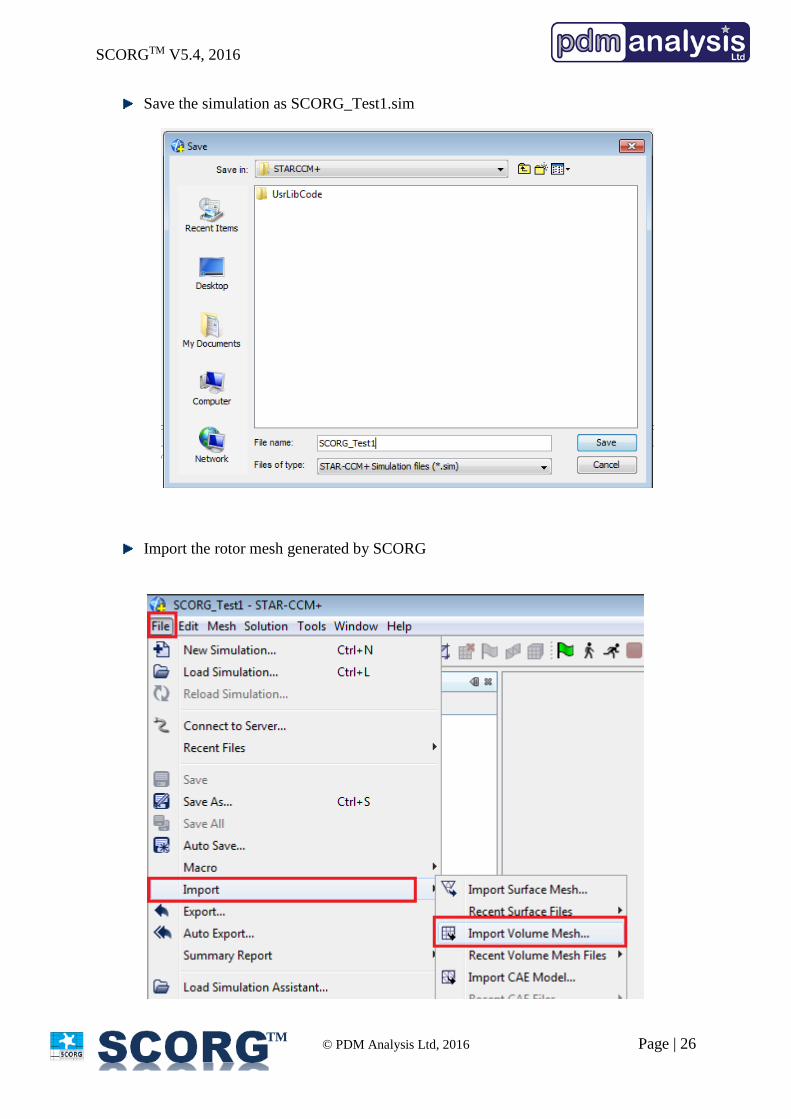
Save the simulation as SCORG_Test1.sim
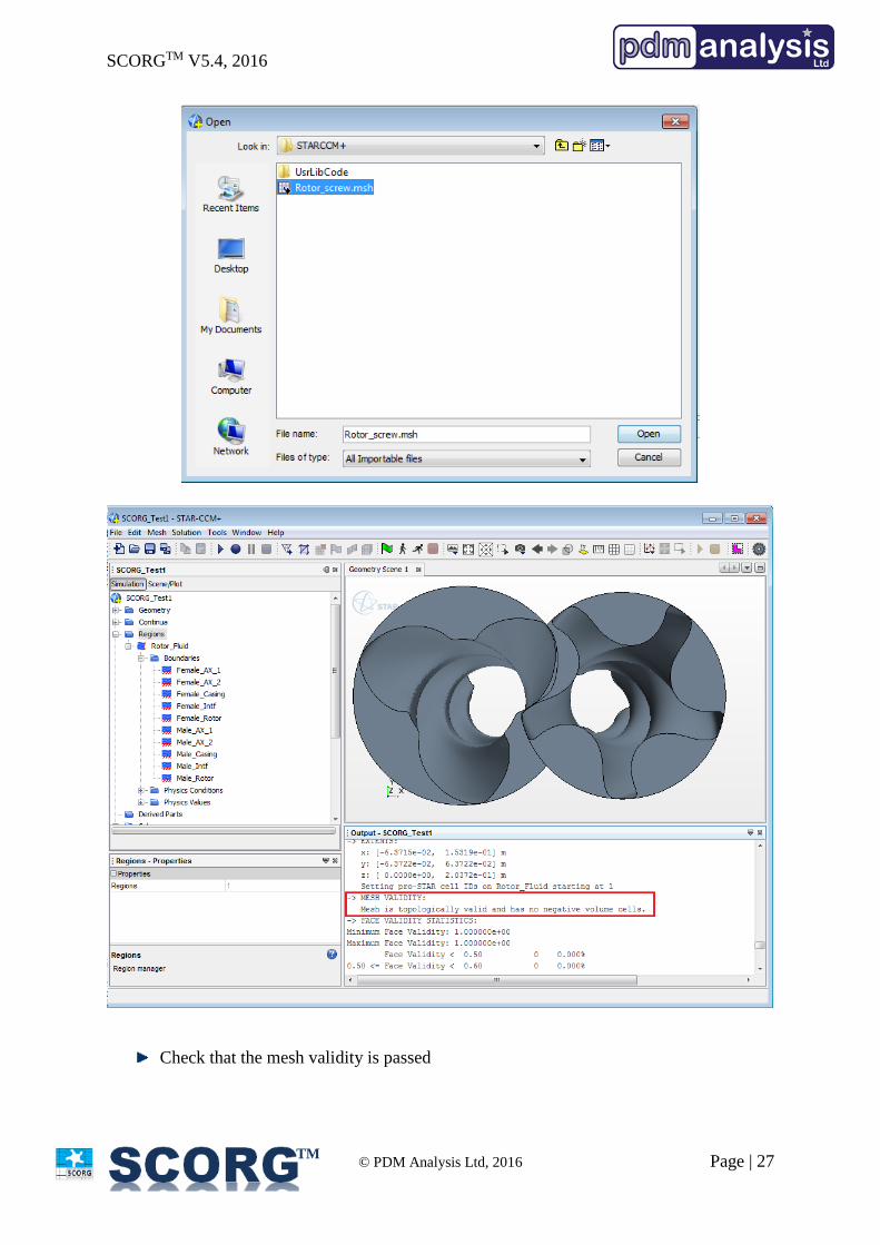
Import the rotor mesh generated by SCORG
SCORGTM V5.4, 2016
© PDM Analysis Ltd, 2016 Page | 27
TM
Check that the mesh validity is passed
SCORGTM V5.4, 2016
© PDM Analysis Ltd, 2016 Page | 28
TM
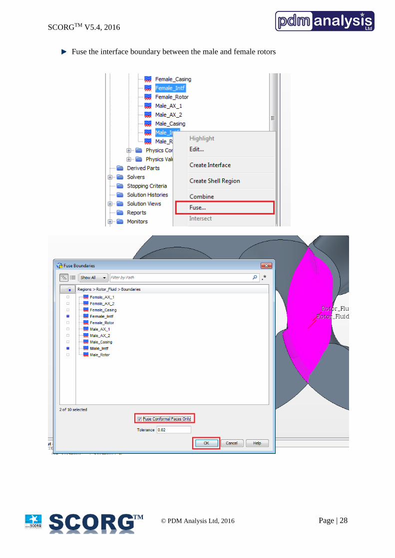
Fuse the interface boundary between the male and female rotors
SCORGTM V5.4, 2016
© PDM Analysis Ltd, 2016 Page | 29
TM
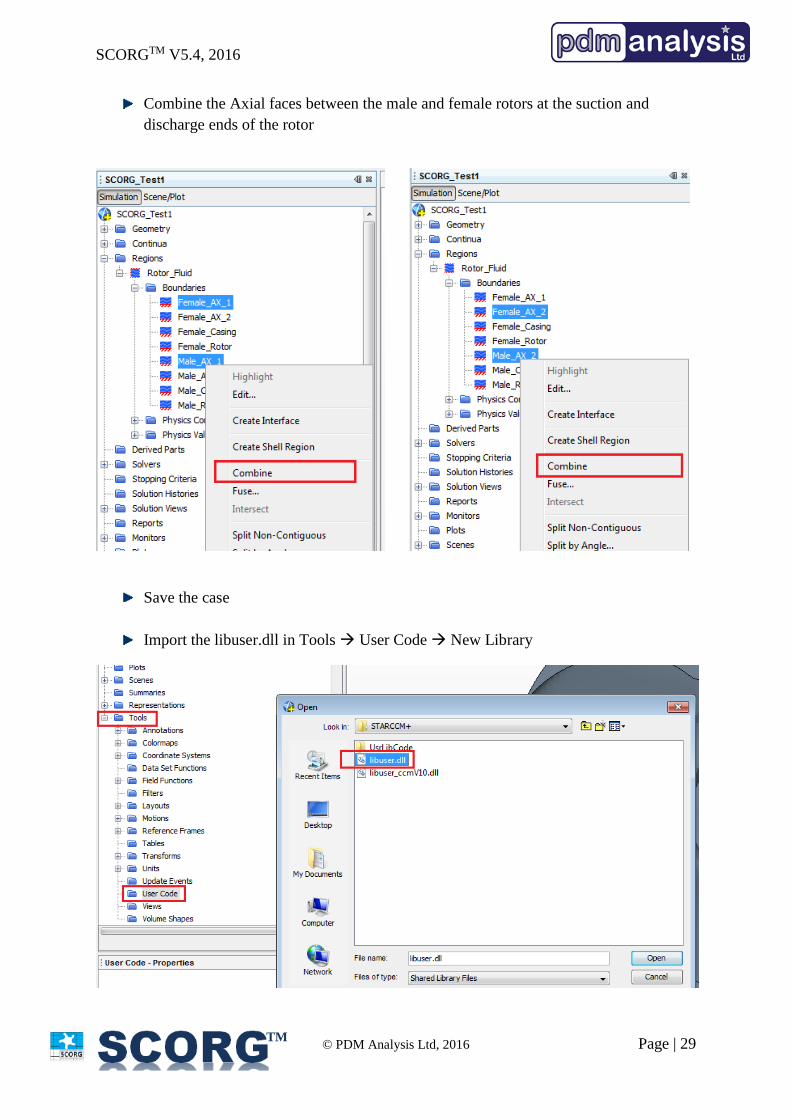
Combine the Axial faces between the male and female rotors at the suction and
discharge ends of the rotor
Save the case
Import the libuser.dll in Tools User Code New Library
SCORGTM V5.4, 2016
© PDM Analysis Ltd, 2016 Page | 30
TM
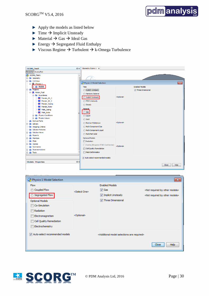
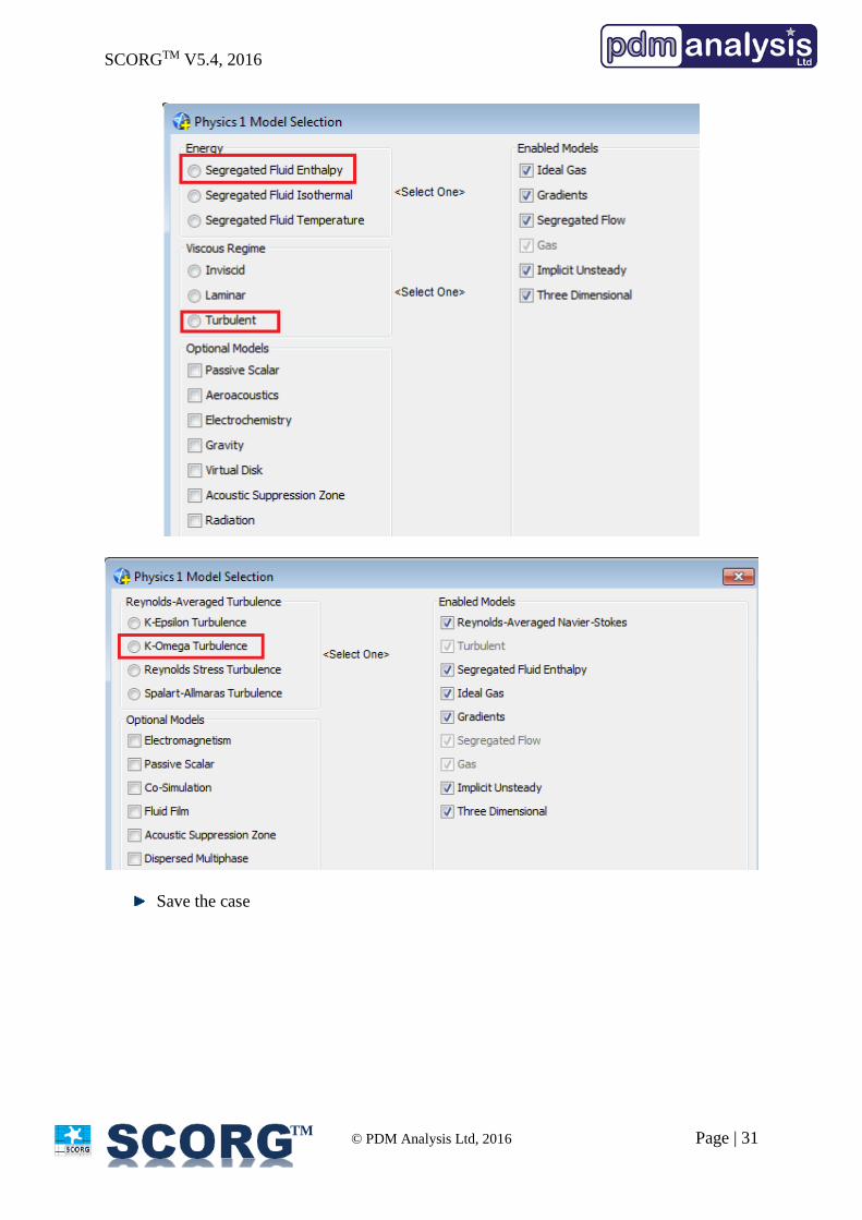
Apply the models as listed below
Time Implicit Unsteady
Material Gas Ideal Gas
Energy Segregated Fluid Enthalpy
Viscous Regime Turbulent k-Omega Turbulence
SCORGTM V5.4, 2016
© PDM Analysis Ltd, 2016 Page | 31
TM
Save the case
SCORGTM V5.4, 2016
© PDM Analysis Ltd, 2016 Page | 32
TM
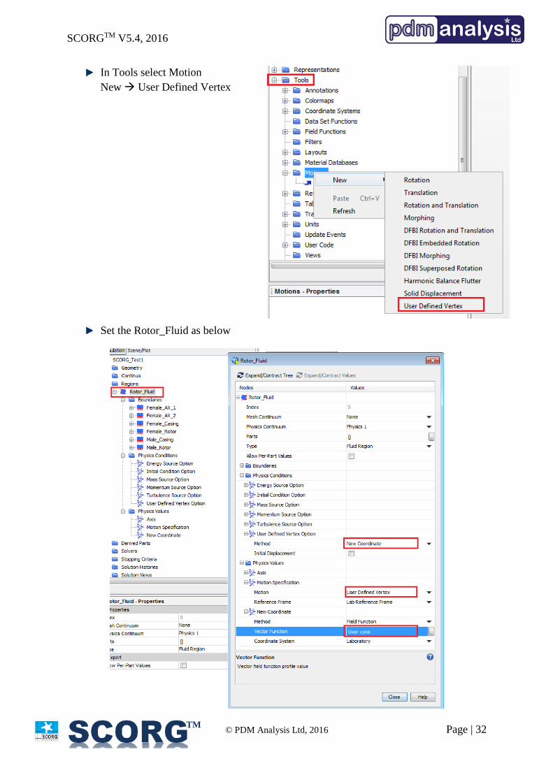
In Tools select Motion
New User Defined Vertex
Set the Rotor_Fluid as below
SCORGTM V5.4, 2016
© PDM Analysis Ltd, 2016 Page | 33
TM
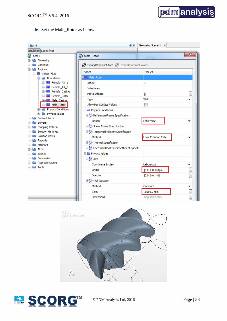
Set the Male_Rotor as below
SCORGTM V5.4, 2016
© PDM Analysis Ltd, 2016 Page | 34
TM
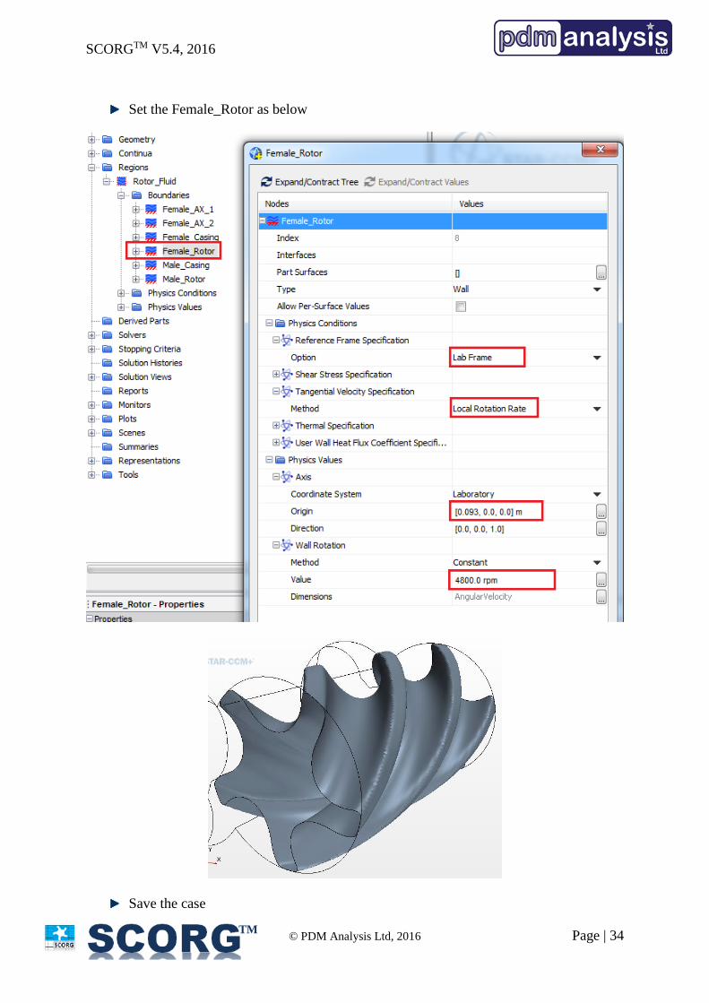
Set the Female_Rotor as below
Save the case
SCORGTM V5.4, 2016
© PDM Analysis Ltd, 2016 Page | 35
TM
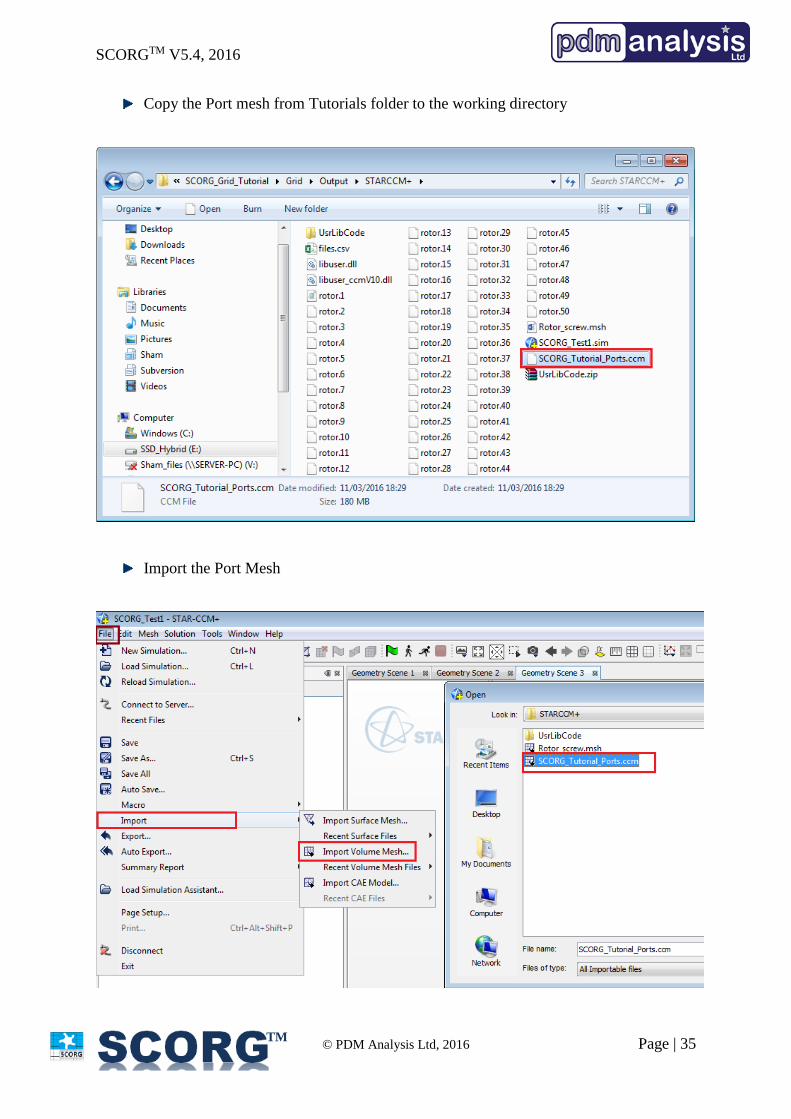
Copy the Port mesh from Tutorials folder to the working directory
Import the Port Mesh
SCORGTM V5.4, 2016
© PDM Analysis Ltd, 2016 Page | 36
TM
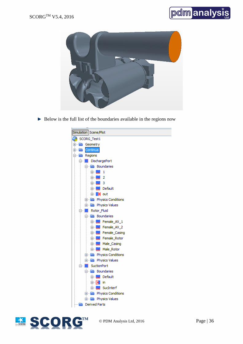
Below is the full list of the boundaries available in the regions now
SCORGTM V5.4, 2016
© PDM Analysis Ltd, 2016 Page | 37
TM
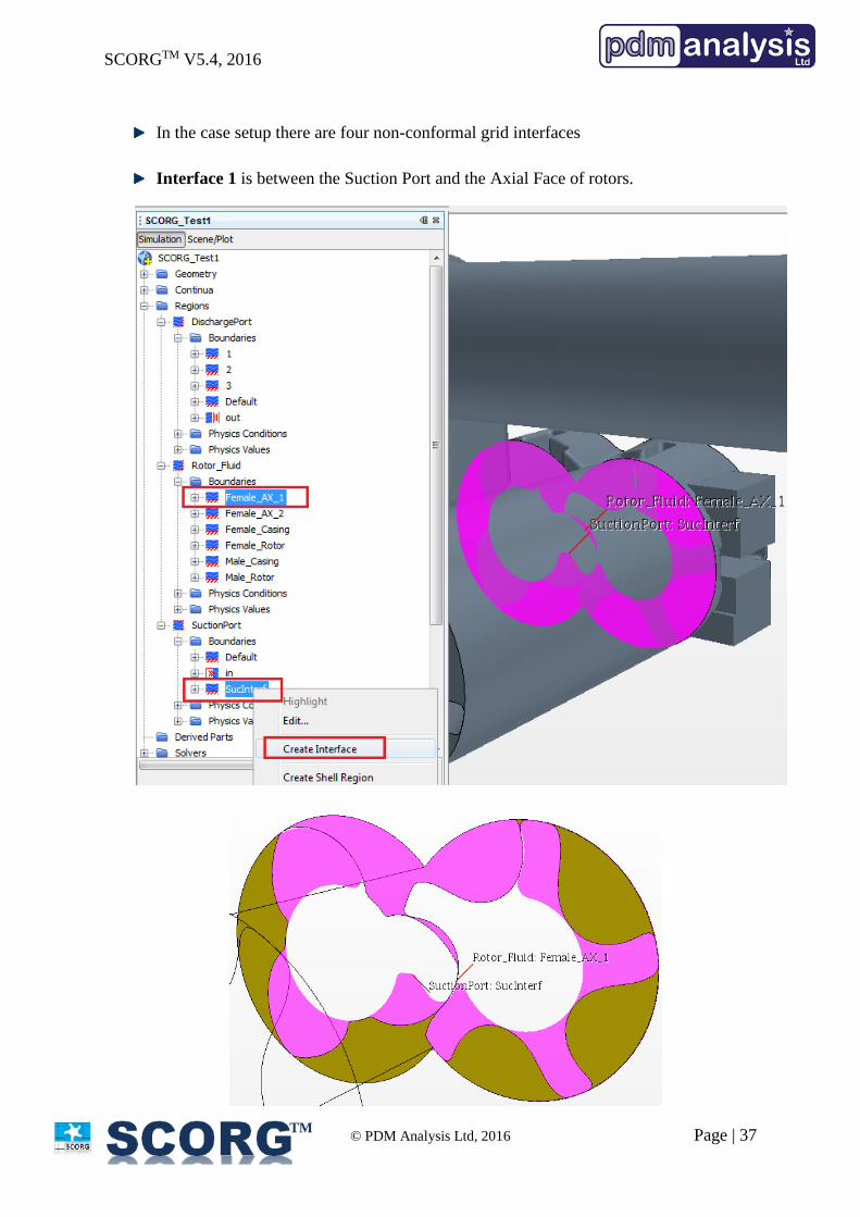
In the case setup there are four non-conformal grid interfaces
Interface 1 is between the Suction Port and the Axial Face of rotors.
SCORGTM V5.4, 2016
© PDM Analysis Ltd, 2016 Page | 38
TM
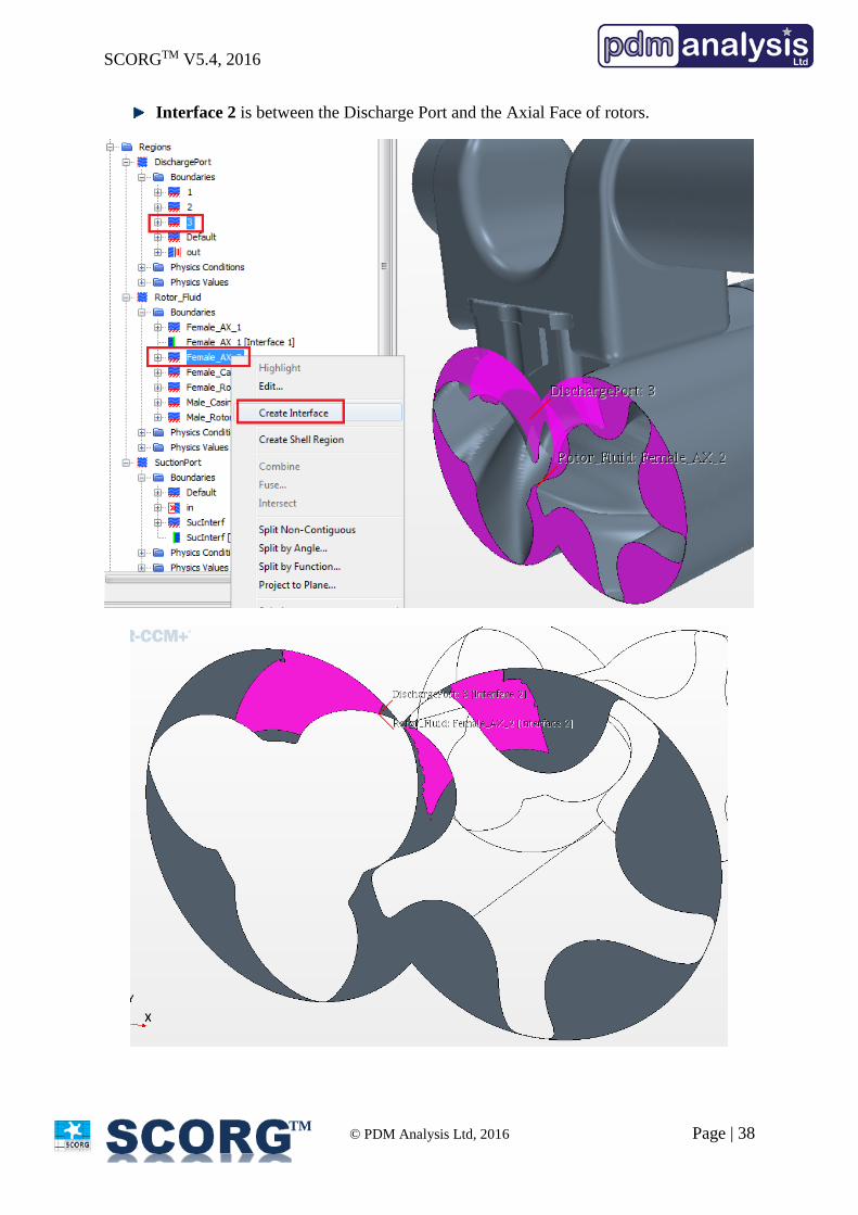
Interface 2 is between the Discharge Port and the Axial Face of rotors.
SCORGTM V5.4, 2016
© PDM Analysis Ltd, 2016 Page | 39
TM
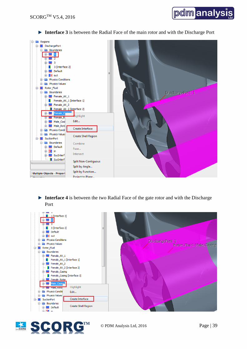
Interface 3 is between the Radial Face of the main rotor and with the Discharge Port
Interface 4 is between the two Radial Face of the gate rotor and with the Discharge
Port
SCORGTM V5.4, 2016
© PDM Analysis Ltd, 2016 Page | 40
TM
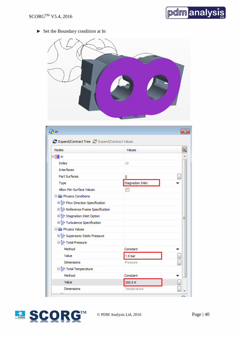
Set the Boundary condition at In
SCORGTM V5.4, 2016
© PDM Analysis Ltd, 2016 Page | 41
TM
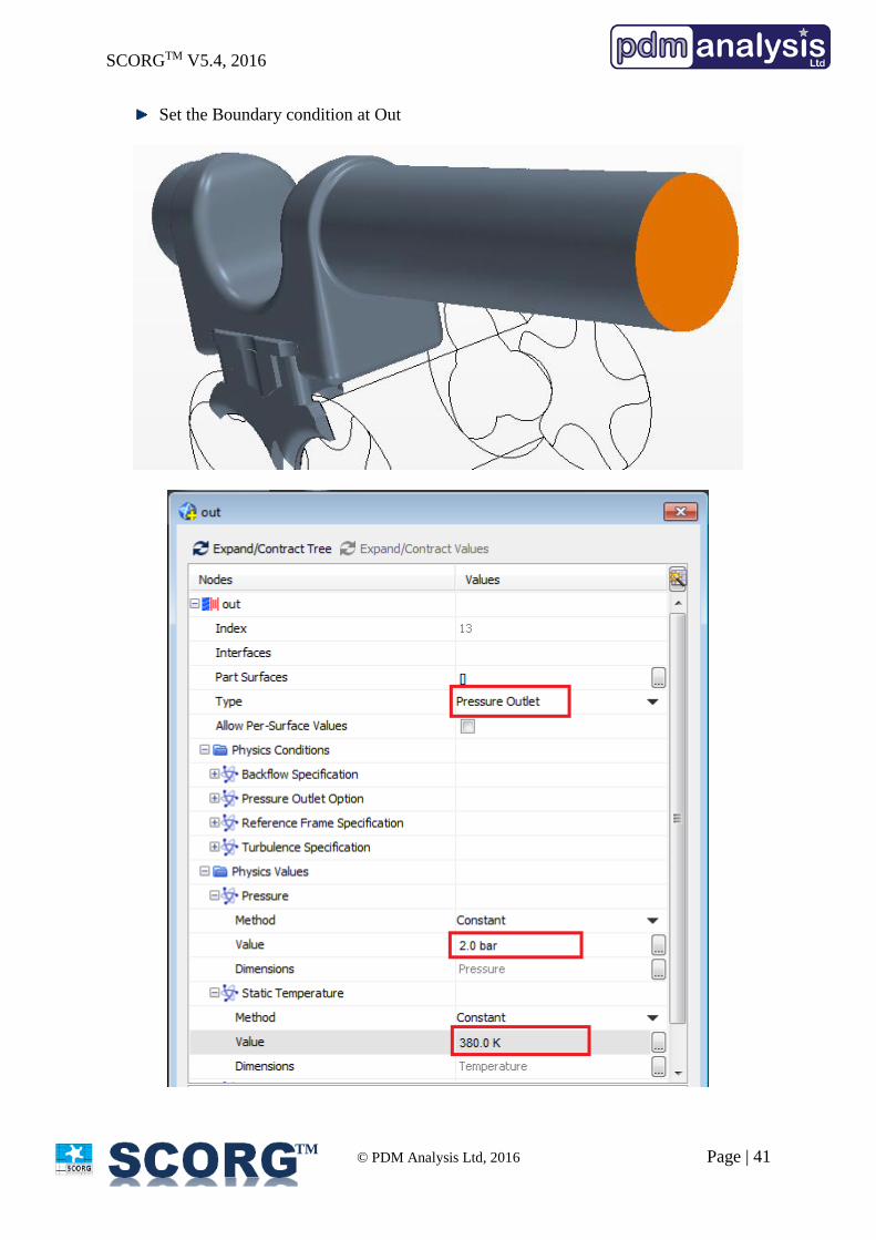
Set the Boundary condition at Out
SCORGTM V5.4, 2016
© PDM Analysis Ltd, 2016 Page | 42
TM
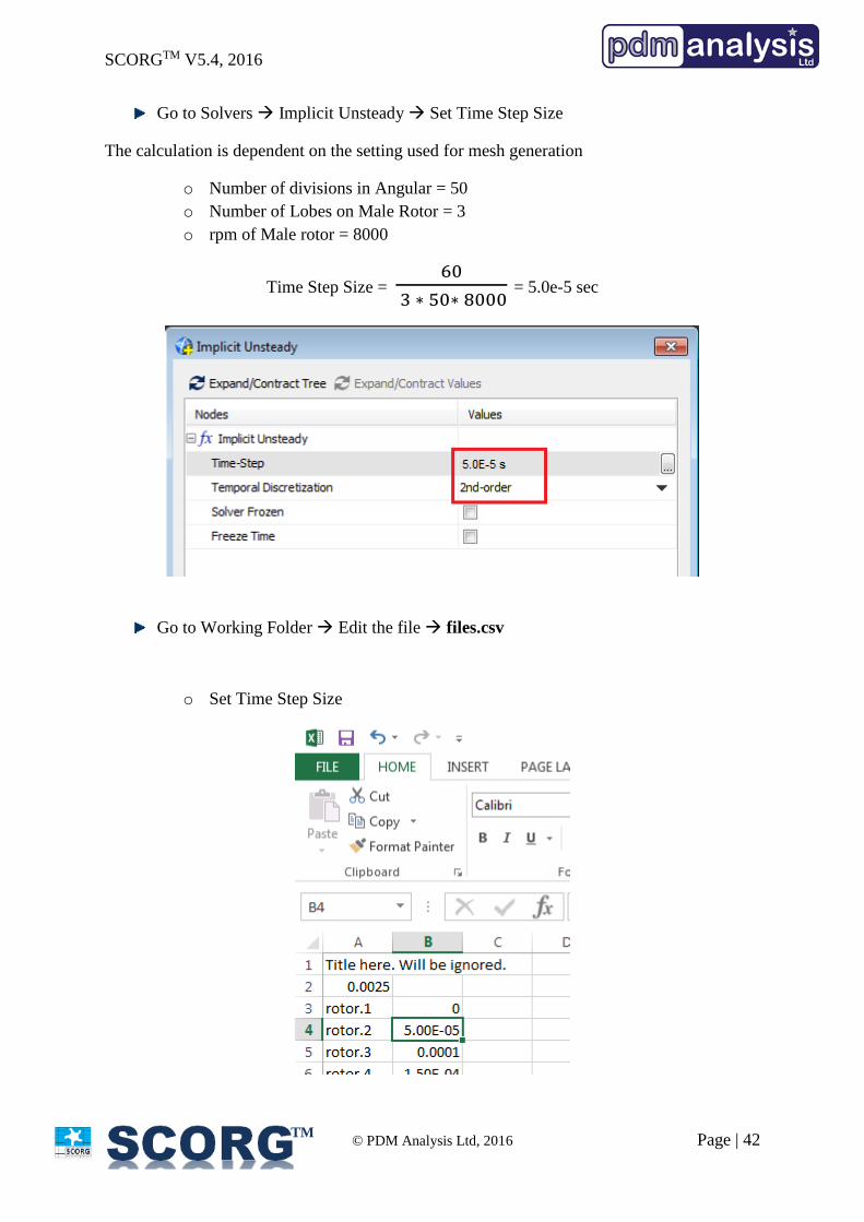
Go to Solvers Implicit Unsteady Set Time Step Size
The calculation is dependent on the setting used for mesh generation
o Number of divisions in Angular = 50
o Number of Lobes on Male Rotor = 3
o rpm of Male rotor = 8000
Time Step Size = 60
3 ∗ 50∗ 8000 = 5.0e-5 sec
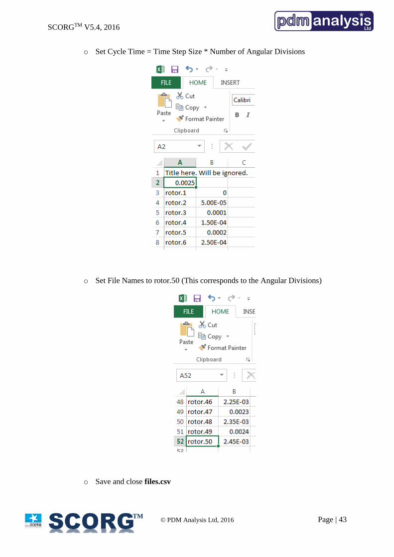
Go to Working Folder Edit the file files.csv
o Set Time Step Size
SCORGTM V5.4, 2016
© PDM Analysis Ltd, 2016 Page | 43
TM
o Set Cycle Time = Time Step Size * Number of Angular Divisions
o Set File Names to rotor.50 (This corresponds to the Angular Divisions)
o Save and close files.csv
SCORGTM V5.4, 2016
© PDM Analysis Ltd, 2016 Page | 44
TM
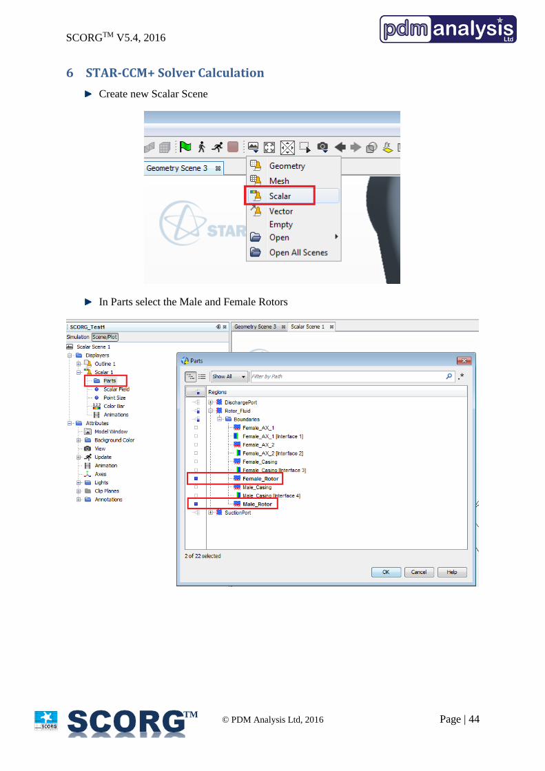
6 STAR-CCM+ Solver Calculation
Create new Scalar Scene
In Parts select the Male and Female Rotors
SCORGTM V5.4, 2016
© PDM Analysis Ltd, 2016 Page | 45
TM
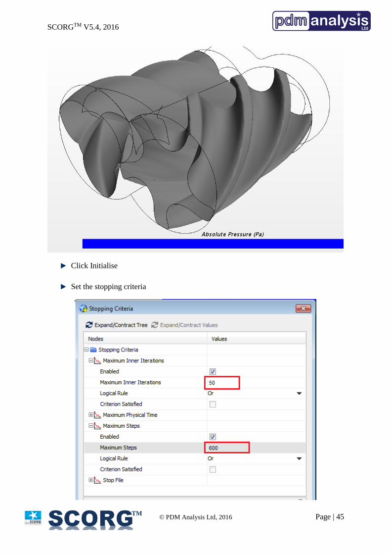
Click Initialise
Set the stopping criteria
SCORGTM V5.4, 2016
© PDM Analysis Ltd, 2016 Page | 46
TM
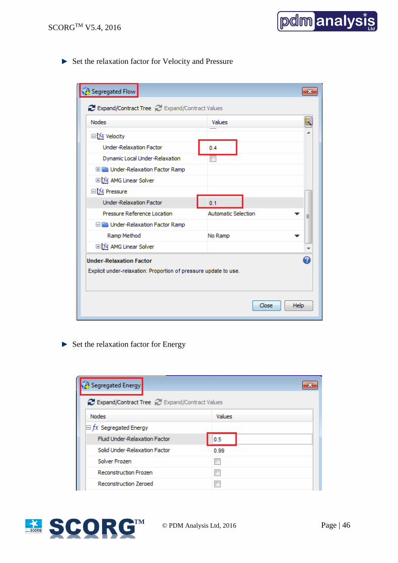
Set the relaxation factor for Velocity and Pressure
Set the relaxation factor for Energy
SCORGTM V5.4, 2016
© PDM Analysis Ltd, 2016 Page | 47
TM
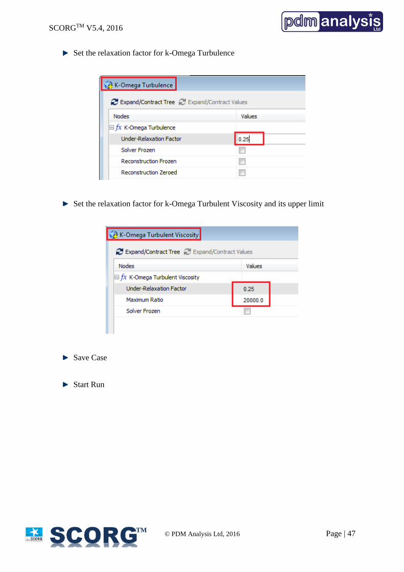
Set the relaxation factor for k-Omega Turbulence
Set the relaxation factor for k-Omega Turbulent Viscosity and its upper limit
Save Case
Start Run
SCORGTM V5.4, 2016
© PDM Analysis Ltd, 2016 Page | 48
TM
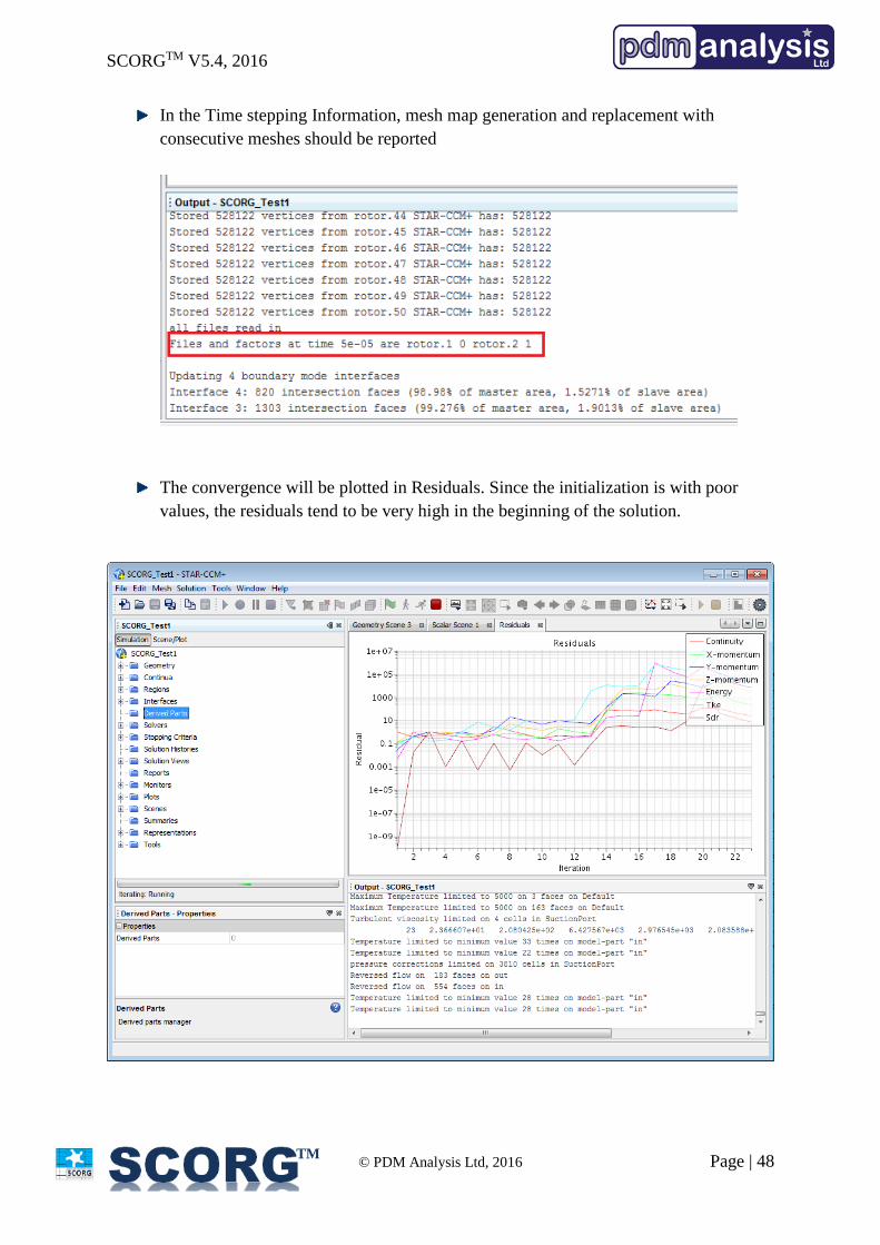
In the Time stepping Information, mesh map generation and replacement with
consecutive meshes should be reported
The convergence will be plotted in Residuals. Since the initialization is with poor
values, the residuals tend to be very high in the beginning of the solution.
SCORGTM V5.4, 2016
© PDM Analysis Ltd, 2016 Page | 49
TM
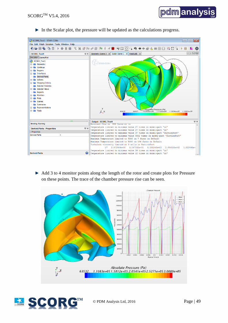
In the Scalar plot, the pressure will be updated as the calculations progress.
Add 3 to 4 monitor points along the length of the rotor and create plots for Pressure
on these points. The trace of the chamber pressure rise can be seen.
SCORGTM V5.4, 2016
© PDM Analysis Ltd, 2016 Page | 50
TM
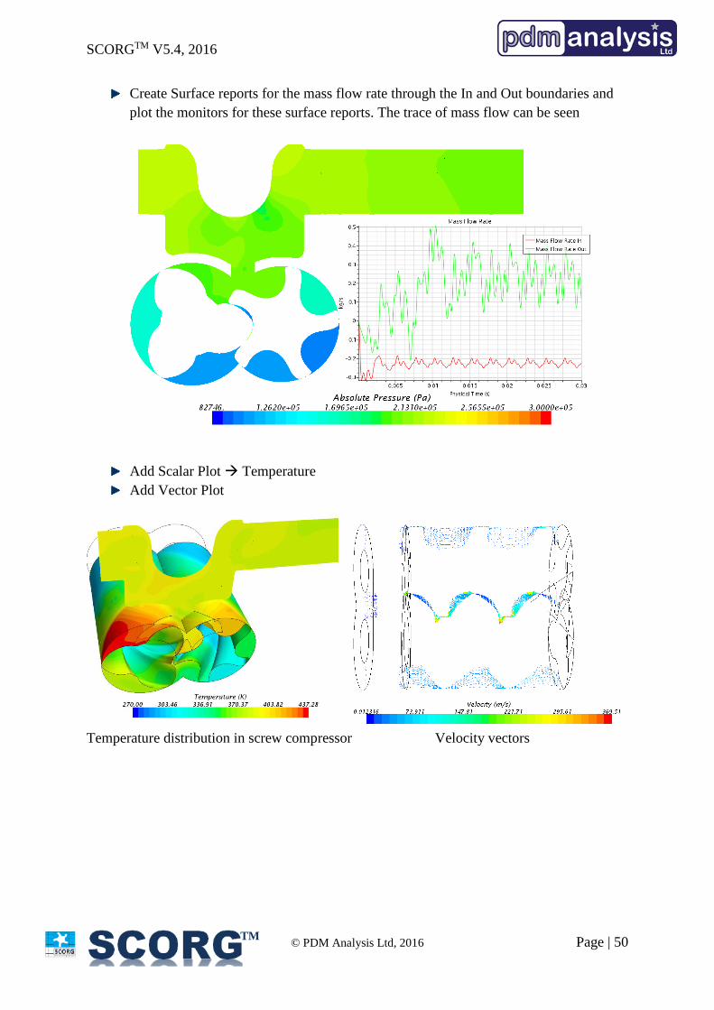
Create Surface reports for the mass flow rate through the In and Out boundaries and
plot the monitors for these surface reports. The trace of mass flow can be seen
Add Scalar Plot Temperature
Add Vector Plot
Temperature distribution in screw compressor Velocity vectors
SCORGTM V5.4, 2016
© PDM Analysis Ltd, 2016 Page | 51
TM
7 Summary
This document describes the steps to setup a STAR-CCM+ model for Screw compressor CFD
analysis using grids generated by SCORGTM Meshing tool. More detailed information on using
SCORG and Screw compressor mesh generation can be found in user guide (SCORG, 2016).
The set of mesh files generated for a complete cycle are reused cyclically when the simulation
is run for more than one cycle. Thus it is possible to continuously run the simulation until
repeatable results in the monitors and good convergence is obtained. It is also possible to stop
and restart the simulation in between, change certain Boundary conditions, Solver control
parameters or save the intermediate results. More detailed information on using STAR-CCM+,
Transient simulations and Post-Processing can be found in user guide (CD Adapco, 2016).
8 Bibliography
CD Adapco, S.-C. V., 2016. User Guide, London: CD Adapco.
DISCO, 2007. DISCO, User Help Manual, London: City University.
Kovacevic, A., Stosic, N. & Smith, I. K., 2007. Screw compressors - Three dimensional
computational fluid dynamics and solid fluid interaction, ISBN 3-540-36302-5. 1 ed. New
York: Springer-Verlag Berlin Heidelberg.
Rane, S., 2015. Grid Generation and CFD analysis of Variable Geometry Screw Machines,
London: City University London.
SCORG, 2016. SCORG, User Help Manual, London: City University.
Stosic, N., Smith, I. K. & Kovacevic, A., 2005. Screw compressors: Mathematical modeling
and performance calculation, ISBN 3540242759. 1 ed. London: Springer.
End of Document
PDM Analysis Ltd 8 Eccleston Close, Barnet, EN4 9EZ, United Kingdom +44 78 2781 8689; +44 20 3489 9018 [email protected] http://www.pdmanalysis.co.uk

![SCORGTM Setup for CFD Simulation of Twin Screw Machines with Simerics Inc…rbbb265/SCORG_Pumplinx_Setup_V5.4.pdf · 2016. 10. 14. · [ SCORG_CFX_Tutorial_Ports_V5.4.cfx ] Copy the](https://img.pdfslide.us/doc/110x75/61154f43d3a83d7da9368315/scorgtm-setup-for-cfd-simulation-of-twin-screw-machines-with-simerics-rbbb265scorgpumplinxsetupv54pdf.jpg)