Embed Size (px)
Citation preview

for Industry
SPECIFICATIONS & DRAWINGS FOR MASS PRODUCTION
3.Mar.2008
G3-29285-0021
3TNV88-BDSA
★

Note:
Manager
Sec.Manager
Checked Drawn
FinalDrawing
ForConference
ForApporval
ForInstallation
Sakamoto
Contents
128300-77920 TIMER, GLOW PLUG 1
for solenoid
119650-77910 RELAY ASSY, GLOW 1 for solenoid
119643-66900 DIODE 1
129242-55700 SEPARATOR ASSY 1
129004-13200 GASKET, SILENCER 1
119225-52102 PUMP, FUEL FEED 1
for solenoid
0ATNV-G00101 OPERATION MANUAL 1
129211-77920 TIMER, SECTION 1 1
114110-07760 LABEL, FUEL OIL CAUT 1
LOOSE PARTS
3TNV88-BDSAW.No.
B3-29285-0010 Out line
E3-29005-0010
BranchExp.Dept.CopyTotal
CustomerQTY
G3-29285-0021
Part No. Name
Wiring Diagram
①Since the durability of electric parts basically apply to R2 level of JIS D0203,pleaseinform the customer not to clean with steam or high pressure water.②Electric parts should not mounted on the engine directly (relay, timer etc.) must bekept free from wet & high humidity and be kept with good air ventilation.Regarding the vibration of the electrical components, these vibration level must be keptless than 4G.③Since there is the possibility of corrosion problem on engine cylinder liner or otherparts,please do not sell and use the engine with EGR valve in other than emissionregulated area.(Emission regulated area means North America,Europe and Japan)
Drawing No.
Z3-19822-0450 Detail of Flywheel
Qty. Remarks
Engine Development Dept.
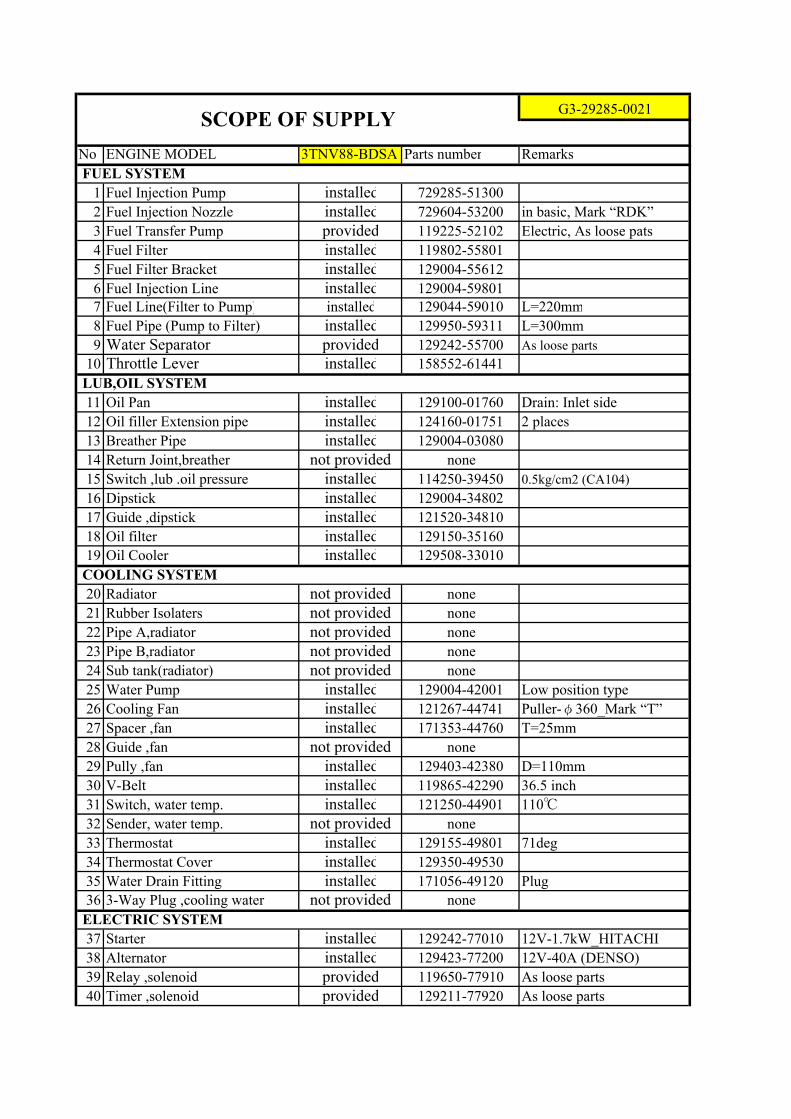
G3-29285-0021 SCOPE OF SUPPLY
★

No
1
2
3
4
5
9
10
14
15
16
17
3TNV88-BDSA
load
100%
↓
0%
intermitted
( ):continuous
13
18
19
20
8 Intermediate torque
11
12
Max.
Min.
Governorbility Governor type
Specific fuel consumption
6 Rated output
7 Gross output
Cooling
system
Coolant capacity
kgf/cm2
liter
Heat exchanger
Pressure cap
Fan
none
kgf/cm2 0.6 at low idle
Lubrication
system
System
Oil grade
Oil filter
Oil capacity
Oil pump
Oil pressure kgf/cm2 4 at rated output
liter 2.8 effective.
liter 6.7 max.
paper element
trochoid pump
API class CD, SAE grade 10W30
forced feed
hole type
paper element
deg FIT13.5(+1.0/-1.0) FIT b.T.D.C
Distributortype(YPD-MP2),Yanmar made
Diesel oilFuel
system
Fuel type
Fuel injection pump
Engine dry weight
Fuel injection timing
Fuel injection nozzle
Fuel filter
kg approx.148
Direction of rotation counterclockwise viewed from F.W.
Firing order 1-3-2-1 order from F.W.
deg 35(30)
Gradients Longitudinal
Lateral
deg 35(30)
min-1 max.22Stability
sec max.6Recovery time
% max.7Permanent
min-1 3210
% max.12Temporary
centrifugal-all speed governor
+25/-25Engine speed at no load
Ambient condition 25℃、750mmHg、30%
1000 +25/-25
g/kW-h(g/PS-h) 263(194) at rated output
min-1 1800(+100/-100)
N・m 98.8~107.7
min-1 3000
kW(PS) 28.2(38.3)
min-1 3000
kW(PS) 26.9(36.6)
Displacement litter 1.642
Compression ratio 19.1
min-1
No.of cylinders-Bore×Stroke mm 3-φ88×90
Combustion system Direct Injection
2
7-φ360
0.9
ENGINE SPECIFICATIONSG3-29285-0021
RemarksModel name 3TNV88-BDSA
Type 4 cycle, Inline,Water-cooled Diesel
★

No
22
25
26
<Career>
3TNV88-BDSA
3TNV88-BDSA
24
27 Applied regulation
Starting
system
Starter
Engine color
Breather system
W.No.
23 Muffler
Generator
Battery
Starting aid
21 Air cleaner none
12V-1.7kW
closed
none
EPA Int4,EC(NRMM)StageⅢA,ARB-OR-Int4
80D26
glow plug(super quick glow)
Silver
12V-40A
ENGINE SPECIFICATIONSG3-29285-0021
Model name 3TNV88-BDSA Remarks
★
G3-29285-0021
No ENGINE MODEL 3TNV88-BDSA Parts number Remarks
FUEL SYSTEM
1 Fuel Injection Pump installed 729285-51300
2 Fuel Injection Nozzle installed 729604-53200 in basic, Mark “RDK”
3 Fuel Transfer Pump provided 119225-52102 Electric, As loose pats
4 Fuel Filter installed 119802-55801
5 Fuel Filter Bracket installed 129004-55612
6 Fuel Injection Line installed 129004-59801
7 Fuel Line(Filter to Pump) installed 129044-59010 L=220mm
8 Fuel Pipe (Pump to Filter) installed 129950-59311 L=300mm
9 Water Separator provided 129242-55700 As loose parts
10 Throttle Lever installed 158552-61441
LUB,OIL SYSTEM
11 Oil Pan installed 129100-01760 Drain: Inlet side
12 Oil filler Extension pipe installed 124160-01751 2 places
13 Breather Pipe installed 129004-03080
14 Return Joint,breather not provided none
15 Switch ,lub .oil pressure installed 114250-39450 0.5kg/cm2 (CA104)
16 Dipstick installed 129004-34802
17 Guide ,dipstick installed 121520-34810
18 Oil filter installed 129150-35160
19 Oil Cooler installed 129508-33010
COOLING SYSTEM
20 Radiator not provided none
21 Rubber Isolaters not provided none
22 Pipe A,radiator not provided none
23 Pipe B,radiator not provided none
24 Sub tank(radiator) not provided none
25 Water Pump installed 129004-42001 Low position type
26 Cooling Fan installed 121267-44741 Puller-φ360_Mark “T”
27 Spacer ,fan installed 171353-44760 T=25mm
28 Guide ,fan not provided none
29 Pully ,fan installed 129403-42380 D=110mm
30 V-Belt installed 119865-42290 36.5 inch
31 Switch, water temp. installed 121250-44901 110℃
32 Sender, water temp. not provided none
33 Thermostat installed 129155-49801 71deg
34 Thermostat Cover installed 129350-49530
35 Water Drain Fitting installed 171056-49120 Plug
36 3-Way Plug ,cooling water not provided none
ELECTRIC SYSTEM
37 Starter installed 129242-77010 12V-1.7kW_HITACHI
38 Alternator installed 129423-77200 12V-40A (DENSO)
39 Relay ,solenoid provided 119650-77910 As loose parts
40 Timer ,solenoid provided 129211-77920 As loose parts
SCOPE OF SUPPLY

41 Engine Shut Off installed 119653-77950 coupler
42 Starting Aid installed 129008-77800
43 Diode ,solenoid relay provided 119643-66900 As loose parts
44 Timer, air heater (glow) provided 128300-77920 As loose parts
45 Relay, air heater (glow) not provided none
46 Current Limiter not provided none
47 Safety relay, starter not provided none
PTO SYSTEM
48 Flywheel Housing or Back plate installed 119888-01601 SAE #5 (124)
49 Flywheel installed 129188-21590 8-M8_PCφ222.5
50 Bearing ,retainer installed 119888-21450
51 Pully ,crankshaft installed 129004-21650 D=110 mm
52 Gear case installed 129604-01500
53 Hydraulic Pump not provided none
54 Device, hydraulic pump not provided none
INTAKE/EXHAUST SYSTEM
55 Air Cleaner not provided none
56 Bracket ,air cleaner not provided none
57 Manifold ,intake installed 129004-12100 Lateral
58 Joint installed 129486-12581 Flywheel side
59 Muffler not provided none
60 Gasket ,muffler provided 129004-13200 As loose parts
61 Manifold ,exhaust installed 129004-13109 Upward
62 Bend ,exhaust not provided none
63 EGR Pipe not provided none
64 EGR Valve not provided none
65 EGR Cooler not provided none
66 Turbine not provided none
ELECTRIC CONTROLL SYSTEM
67 ECU not provided none
68 Main Relay not provided none
69 Lack Actuator Relay not provided none
70 Starter Relay not provided none
GAUGE
71 Drive Unit ,tachometer not provided none
72 Cable ,tachometer not provided none
73 Tachometer not provided none
74 Key Switch not provided none
75 Cover ,terminals not provided none
76 Pilot lamp not provided none
77 Gauge ,oil/water temp not provided none
78 Gauge ,oil pressure not provided none
OTHERS
79 Filter Wrench ,lub .oil not provided none
80 Filter Wrench ,fuel .oil not provided none


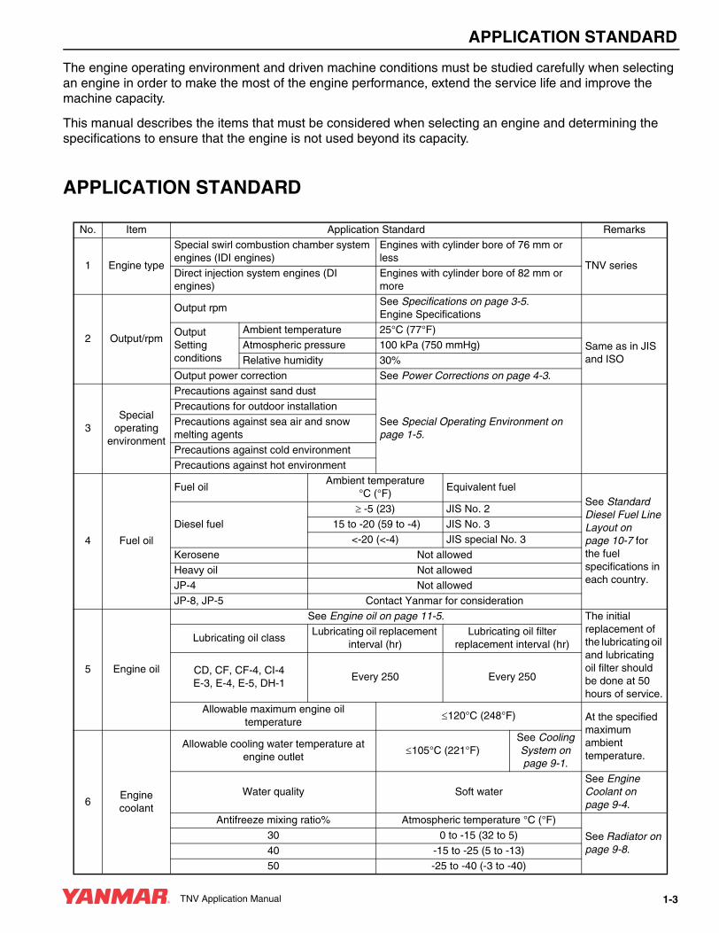
APPLICATION STANDARD
TNV Application Manual 1-3
The engine operating environment and driven machine conditions must be studied carefully when selecting an engine in order to make the most of the engine performance, extend the service life and improve the machine capacity.
This manual describes the items that must be considered when selecting an engine and determining the specifications to ensure that the engine is not used beyond its capacity.
APPLICATION STANDARD
No. Item Application Standard Remarks
1 Engine type
Special swirl combustion chamber system engines (IDI engines)
Engines with cylinder bore of 76 mm or less
TNV seriesDirect injection system engines (DI engines)
Engines with cylinder bore of 82 mm or more
2 Output/rpm
Output rpmSee Specifications on page 3-5.Engine Specifications
Output Setting conditions
Ambient temperature 25°C (77°F)
Same as in JIS and ISO
Atmospheric pressure 100 kPa (750 mmHg)
Relative humidity 30%
Output power correction See Power Corrections on page 4-3.
3Special
operating environment
Precautions against sand dust
See Special Operating Environment on page 1-5.
Precautions for outdoor installation
Precautions against sea air and snow melting agents
Precautions against cold environmentPrecautions against hot environment
4 Fuel oil
Fuel oilAmbient temperature
°C (°F)Equivalent fuel
See Standard Diesel Fuel Line Layout on page 10-7 for the fuel specifications in each country.
Diesel fuel
≥ -5 (23) JIS No. 2
15 to -20 (59 to -4) JIS No. 3<-20 (<-4) JIS special No. 3
Kerosene Not allowed
Heavy oil Not allowedJP-4 Not allowed
JP-8, JP-5 Contact Yanmar for consideration
5 Engine oil
See Engine oil on page 11-5. The initial replacement of the lubricating oil and lubricating oil filter should be done at 50 hours of service.
Lubricating oil classLubricating oil replacement
interval (hr)Lubricating oil filter
replacement interval (hr)
CD, CF, CF-4, CI-4E-3, E-4, E-5, DH-1
Every 250 Every 250
Allowable maximum engine oil temperature
≤120°C (248°F) At the specified maximum ambient temperature.
6Engine coolant
Allowable cooling water temperature at engine outlet
≤105°C (221°F)See Cooling System on page 9-1.
Water quality Soft waterSee Engine Coolant on page 9-4.
Antifreeze mixing ratio% Atmospheric temperature °C (°F)
See Radiator on page 9-8.
30 0 to -15 (32 to 5)
40 -15 to -25 (5 to -13)50 -25 to -40 (-3 to -40)
TNV_Application.book 3 ページ 2006年10月24日 火曜日 午後7時18分

APPLICATION STANDARD
1-4 TNV Application Manual
7Power take-
off (PTO)See P.T.O. Systems on page 15-1.
8Low-temperature startability
See Low-temperature startability on page 1-7.
9Allowable inclination angle
Continuous operation All directionsIDI ≤25° See Crankcase
Breather System on page 11-18.
DI ≤30°
Instantaneous operation (within 3 minutes) All directionsIDI ≤30°DI ≤35°
10
Allowable exhaust back pressure
See Allowable Air Intake Restriction and Exhaust Back Pressures on page 1-30.
11
Allowable air restriction at intake manifold
No. Item Application Standard Remarks
TNV_Application.book 4 ページ 2006年10月24日 火曜日 午後7時18分

APPLICATION STANDARD
TNV Application Manual 1-5
SPECIAL OPERATING ENVIRONMENT The engine performance depends greatly on the operating and environmental conditions.
Please consult with Yanmar when unusual operating conditions exist.
Precautions Against Dusty Conditions
Precautions for Outdoor Installation
(*) Level R2: A water spraying test level for checking the performance of the portion subject to indirect exposure to rainwater or splashing water.
Precautions Against Salty Conditions (Air, Sea Water, Road Salt)
Condition Part Countermeasure
Wear due to dusty or sandy condition
Air cleaner
The following measures and cleaning are necessary to prevent dust from entering the engine:Use double element (safety element)Use evacuator valveUse dust indicator
Alternator Dust-proof type may be required for preventing entry of sand and dust.Starting motor
Breather air reservoir (for turbocharged engine only)
Since dust can enter from the breather pipe while the engine is stopped, an air reservoir may be installed at the end of the breather pipe.
Cooling fanto improve the wear resistance, a fan made of nylon 6 (reinforced with glass fiber) or steel may be required.
V pulleyTo improve the wear resistance, a hardened pulley may be required.
V-beltTo counteract belt wear, a larger type V-belt may be required.
RadiatorChanging the core type and fin material may be required. Heat balance check after the modification is required.
Condition Part Countermeasure
Rain, snow, etc.
Rain cap (for both air cleaner and exhaust silencer)
Entry of rainwater, snow, etc. must be prevented.
Electrical partsSince electrical parts correspond to level R2(*) in JIS D 0203, either install them where they will not be splashed with water, or provide covers.
Location ------------------ Flat, well-ventilated place
Condition Part Countermeasure
Location exposed to salt air or road salt
Electrical parts
Since corrosion may occur, careful maintenance is necessary.
Speed control lever shaftStop lever shaft
Exhaust manifold bolts
Stop lever return spring
RadiatorLocation where salt water may splash directly onto the engine
------------------Do not install engine where it can be splashed with salt water.
TNV_Application.book 5 ページ 2006年10月24日 火曜日 午後7時18分

APPLICATION STANDARD
1-6 TNV Application Manual
Precautions Against Cold Environment
Precautions Against Hot Environment
Others
Environmental temperature Part Countermeasure Remarks
-30°C (-22°F) or aboveBattery (high CCA) Specification must be
changed.
See Low-temperature startability on page 1-7 for startability.
Starting motor
-30°C to -40°C (-22°F to -40°F)
Cooling water hose Special rubber may be required to prevent rubber parts from being damaged by hardening. Choose components that will maintain flexibility at this temperature range.
Intake air hose
O-ringsOil seal
Fuel hose
Fuel feed pumpAn electric feed pump is required.
Starting aid A block heater should be used.-40°C (-40°F) or below Not recommended.
Environmental temperature Part Countermeasure
Below 40°C (104°F) Electrical partsThe temperature inside the engine hood must be kept below 80°C (176°F) to protect the electrical parts. Provide ventilation around electrical parts.
Above 40°C (104°F)
Radiator A large capacity radiator and fan must be used to prevent the cooling water and lubricating oil temperatures from getting too hot.Cooling fan
Oil cooler Increase capacity or install as standard equipment.
Electrical partsThe temperature inside the engine hood must be kept below 80°C (176°F) to protect the electrical parts. Provide ventilation around electrical parts.
Condition Part Countermeasure
Location where explosive, flammable or toxic gas exists
------------------Engine is not designed for installation where explosive, flammable or toxic gas exists.
TNV_Application.book 6 ページ 2006年10月24日 火曜日 午後7時18分

DIESEL FUEL SYSTEM
10-10 TNV Application Manual
Layout for DI Engines with MP2 or MP4 Type Fuel Injection Pump
Fuel Line Layout for DI Engines.
Figure 10-5
Note: Keep return line (a) away from diesel fuel outlet (b) to prevent the diesel fuel line from drawing in air and / or hot diesel fuel. NEVER connect return line (a) to the inlet line.
Diesel Fuel System Part Names and Functions for DI Engines
Note: Mechanical feed pump is not available for DI engines.
No. Part name Function(1) Diesel Fuel Filter /
Water separatorSame as IDI engine.
(2) Diesel fuel filter Has 5 μm mesh paper element inside. Capacity to resist pressure is 7 kg/cm2. There is a valve on the inlet of the fuel filter for air bleeding.
(3) Diesel fuel pump Sends fuel to the fuel injection pump from fuel tank.Electric Mounted off the engine. Consult Yanmar before using a non-Yanmar fuel
pump. An additional check valve is not necessary on the Yanmar electric fuel pump since it has one built in.Note: On a bench test, diesel fuel injection pump performance was
not influenced by a minimum voltage of 10 V.
AB
C
ab
Return fuel
➁ Fuel filter
Fuel injection pump(MP Pump)
➂ Fuel feed pump
➀ Water separator
Fuel tank
D
TNV_Application.book 10 ページ 2006年10月24日 火曜日 午後7時18分

DIESEL FUEL SYSTEM
TNV Application Manual 10-11
Fuel Line Layout (DI engines)
Parts Specification for Engine
For poor quality fuel
Position Standard value Content
A 50 ~ 150 mmFrom fuel filter outlet to fuel injection pump inlet.For air bleeding, fuel filter outlet position should be higher than the fuel injection pump inlet position.
B ≤ 1000 mmTotal head of diesel fuel pump (from diesel fuel tank outlet to injection pump inlet)
C ≤ 400 mmSuction head in dry conditions (from diesel fuel tank outlet to diesel fuel pump inlet)
D ≤ 2000 mmSuppression of the suction side resistance at of the fuel feed pump(from diesel fuel tank outlet to diesel feed pump inlet)
Engine model
3TNV82A ~ 4TNV98
Diesel fuel pump
Electric type: 119225-52102 (standard), 129612-52100 (with water proof coupler)
Diesel fuel filter / water separator
Standard :Filter mesh:Water reservoir:
129242-55700 (fuel inlet & outlet horizontal)100 mesh (with valve)150 cc
Diesel fuel filter
Bracket:Filter:Filter mesh:Filtration size:
129004-55612 (with automatic air bleeding hole φ0.7)119802-558005 μm2000 cm2
Engine model
4TNV98T
Diesel fuel pump
Same as 3TNV82A ~ 4TNV98
Diesel fuel filter / water separator
Same as 3TNV82A ~ 4TNV98
Fuel filter
Bracket:Filter:Filter mesh:Filtration size:
123907-55610123907-558005 μm5000 cm2
3TNV82A to 4TNV98FilterFilter meshFiltration size
129004-558001 μm1650 cm2
129907-558001 μm4000 cm2
4TNV98TFilterFilter meshFiltration size
129907-558001 μm4000 cm2
TNV_Application.book 11 ページ 2006年10月24日 火曜日 午後7時18分