Embed Size (px)
Citation preview
This document is the property of Astrium. It shall not be communicated to third parties
without prior written agreement. Its content shall not be disclosed. EADS/Astrium
TRP and GSTP activity
Spacecraft Controller On a Chip (SCOC3)
ASIC Manufacturing, Test and Validation
EXECUTIVE SUMMARY
EUROPEAN SPACE AGENCY CONTRACT REPORT
The work described in this report was done under ESA contract.
Responsibility for the content resides in the author or the organisation that prepared it.
ESTEC Contract No. 22358/09/NL/JK
Prepared by: Aurélien LEFEVRE
EADS Astrium
1, boulevard Jean Moulin
ZAC de la Clef Saint Pierre - CS 30503
78997 Elancourt Cedex
FRANCE
This document is the property of Astrium. It shall not be communicated to third parties
without prior written agreement. Its content shall not be disclosed. EADS/Astrium
*Section to be completed by ESA
ESA STUDY CONTRACT REPORT
No ESA study Contract Report will be accepted unless this sheet is inserted at the beginning of each volume of the Report
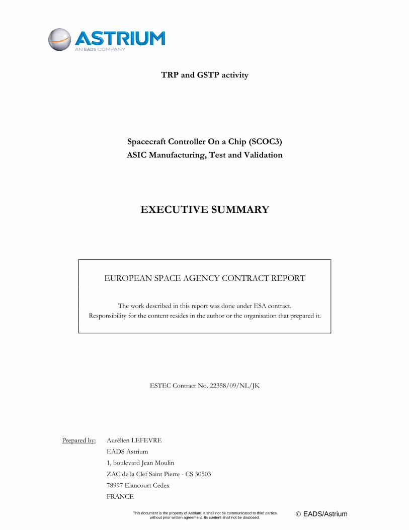
ESA Contract No:
22358/09/NL/JK
SUBJECT:
Spacecraft Controller on Chip (SCOC3) ASIC
Manufacturing and Test
CONTRACTOR:
Astrium SAS
* ESA CR N°
No of Volumes: 1
This is volume n°1
CONTRACTOR'S
REFERENCE:
R&D.SCOC3.RP.01377.E.AS
TR Issue 0 Rev 1
ABSTRACT:
The goal of the “Spacecraft Controller on Chip (SCOC3) ASIC Manufacturing and Test” contract was to
perform the gate-level design, layout, manufacturing and validation of the SCOC3 ASIC, to produce a first level
of basic SW and to prepare SCOC3 commercialisation.
SCOC3 was developed with a very high level of integration of functions to satisfy the demand for increasing
performance at reduced power and mass. The increasing amount of functionalities integrated into the same ASIC
implies that the development of a whole system relies on the use of pre-developed and pre-tested IP functions.
The ideal scenario is to be able to construct a whole system by “simply” integrating IP blocks. This is often
difficult. In reality, IP blocks usually have to be modified, but these IP blocks should always be very well tested
and have a well-known history. The gate level design methodology previously used for ASIC developments has
been improved to focus on the validation of the whole system and to take into account its greater complexity.
The extensive validation campaign was performed using two different boards. In addition to the test cases which
had been performed before the ASIC manufacturing in simulation or on FPGA, new tests were introduced,
testing SCOC3 under various operating conditions, to confirm the functionality and the electrical and timing
parameters, as well as the completeness of the user documentation. These tests were performed by HW teams
and by SW teams. The availability of a basic SW is essential for a System-on-Chip. This need was partly addressed
by the development of a non-flight basic SW. Finally, SCOC3 successfully underwent a radiation test.
Several tools have been developed outside of this contract, such as a Simulator for SW development and a low-
cost FPGA platform. Combined with services such as technical support, this forms a complete offer around the
SCOC3 ASIC to best serve our customers.
The work described in this report was done under ESA contract. Responsibility for the contents resides in the
author or organisation that prepared it.
Names of authors:
Aurélien LEFEVRE (EADS Astrium)
ESA STUDY MANAGER:
Mr Roland WEIGAND
DIV: Data Systems Division
(TEC-EDM)
DIRECTORATE: Technical
and Quality Management
ESA BUDGET HEADING:
TRP activity T701-099ED, budget line:
D/TEC/ESTEC/E/0901-
01/6171000//E/0901-01-K-01/09J12
GSTP activity G603-35ES, budget line:
D/TEC/ESTEC/E/0904-
04/6171000//E/0904-01-K-01/09J17
SCOC3
Ref: R&D.SCOC3.RP.01377.E.ASTR Issue : 1 Rev.: 0 Date : 2013/01/15 Page : 4
This document is the property of Astrium. It shall not be communicated to third parties
without prior written agreement. Its content shall not be disclosed. EADS/Astrium
DOCUMENT CHANGE LOG
Issue/
Revision Date Modification Nb Modified pages Observations
0/0 2012/05/11 First Issue
0/1 2012/07/05 Took ESA QAR comments into account
1/0 2013/01/15 Added the radiation test results
PAGE ISSUE RECORD Issue of this document comprises the following pages at the issue shown
Page Issue/
Rev. Page
Issue/
Rev. Page
Issue/
Rev. Page
Issue/
Rev. Page
Issue/
Rev. Page
Issue/
Rev.
all 1/0
SCOC3
Ref: R&D.SCOC3.RP.01377.E.ASTR Issue : 1 Rev.: 0 Date : 2013/01/15 Page : 5
This document is the property of Astrium. It shall not be communicated to third parties
without prior written agreement. Its content shall not be disclosed. EADS/Astrium
TABLE OF CONTENTS
1 INTRODUCTION .............................................................................................................................................. 7
1.1 CONTEXT AND RELEVANCE OF THE STUDY .......................................................................................................................... 7 1.2 ACRONYMS ................................................................................................................................................................................. 7
2 DESIGN OBJECTIVES AND CONSTRAINTS .............................................................................................. 11
2.1 BACKGROUND .......................................................................................................................................................................... 11 2.2 DESIGN OBJECTIVES ................................................................................................................................................................ 11
3 MAIN TOPICS .................................................................................................................................................. 13
3.1 SCOC3 DEVELOPMENT FLOW .............................................................................................................................................. 13 3.2 GATE-LEVEL DESIGN .............................................................................................................................................................. 14
3.2.1 SCOC3 synthesis and static timing analysis ............................................................................................................................. 14 3.2.2 SCOC3 gate-level simulations ................................................................................................................................................. 16 3.2.3 SCOC3 formal proof .............................................................................................................................................................. 18 3.2.4 SCOC3 preliminary floorplan ................................................................................................................................................. 18 3.2.5 SCOC3 foundry test programs ................................................................................................................................................. 18
3.3 LAYOUT AND MANUFACTURING ........................................................................................................................................... 19 3.4 ASIC VALIDATION .................................................................................................................................................................. 22 3.5 SW DEVELOPMENT ................................................................................................................................................................. 23 3.6 COMMERCIALISATION ............................................................................................................................................................. 24 3.7 RADIATION TEST ..................................................................................................................................................................... 26
4 FOLLOW-UP ACTIVITIES ............................................................................................................................. 27
5 CONCLUSION .................................................................................................................................................. 28
SCOC3
Ref: R&D.SCOC3.RP.01377.E.ASTR Issue : 1 Rev.: 0 Date : 2013/01/15 Page : 6
This document is the property of Astrium. It shall not be communicated to third parties
without prior written agreement. Its content shall not be disclosed. EADS/Astrium
LIST OF FIGURES
Figure 1: SCOC3 Development Flow ...................................................................................................................... 13
Figure 2: SCOC3 clock tree ....................................................................................................................................... 15
Figure 3: Overview of a Modelsim simulation ........................................................................................................ 16
Figure 4: Status of the gate-level simulations .......................................................................................................... 17
Figure 5: Clock definition for the functional foundry test program ................................................................... 19
Figure 6: SCOC3 preliminary Floorplan .................................................................................................................. 20
Figure 7: View of a SCOC3 die showing the final layout ..................................................................................... 20
Figure 8: SCOC3 ASIC mounted on a board ......................................................................................................... 21
Figure 9: SW Package (Basic SW and Demonstration SW) .................................................................................. 23
Figure 10: SCOC3 Complete Offer .......................................................................................................................... 24
Figure 11: SCOC3 Starter Kit (STARKIT): FPGA-based evaluation platform ................................................ 25
Figure 12: SCOC3 test board under the radiative beam ....................................................................................... 26
SCOC3
Ref: R&D.SCOC3.RP.01377.E.ASTR Issue : 1 Rev.: 0 Date : 2013/01/15 Page : 7
This document is the property of Astrium. It shall not be communicated to third parties
without prior written agreement. Its content shall not be disclosed. EADS/Astrium
1 INTRODUCTION
1.1 CONTEXT AND RELEVANCE OF THE STUDY
The objective of the Spacecraft-Controller-On-a-Chip (SCOC) series of activities was to produce a very
integrated and cost-effective solution for spacecraft control. This solution is the SCOC3 System-on-Chip
ASIC that integrates most of the functions of an On Board Data Handling system, and significantly
reduces the cost of embedded electronics.
In 2001-2003, Astrium developed a SCOC prototype design, SCOC1, along with an evaluation board,
BLADE, in the frame of ESA contract #13345/99/NL/FM entitled “Building Blocks for System On-a-
Chip”.
In 2003-2006, Astrium refined this SCOC prototype design into SCOC2, through internal R&D activities.
In 2006-2009, Astrium started the development of the SCOC3 System-on-Chip in the frame of ESA
contract #20167/06/NL/FM entitled “Further Development of the Spacecraft Controller on a Chip”,
during which the architectural design (VHDL, simulation and FPGA prototyping) was performed.
The present activity, under ESA contract #22358/09/NL/JK, is the continuation of these 3 studies. The
aim of this activity is:
to perform the gate-level design of the SCOC3 ASIC
to perform the layout of the ASIC
to manufacture the ASIC
to validate the ASIC, using boards specifically developed for this purpose
to develop a SW package comprising SW tools and a first level of basic SW
to prepare the commercialisation of SCOC3 and its establishment as an ASSP
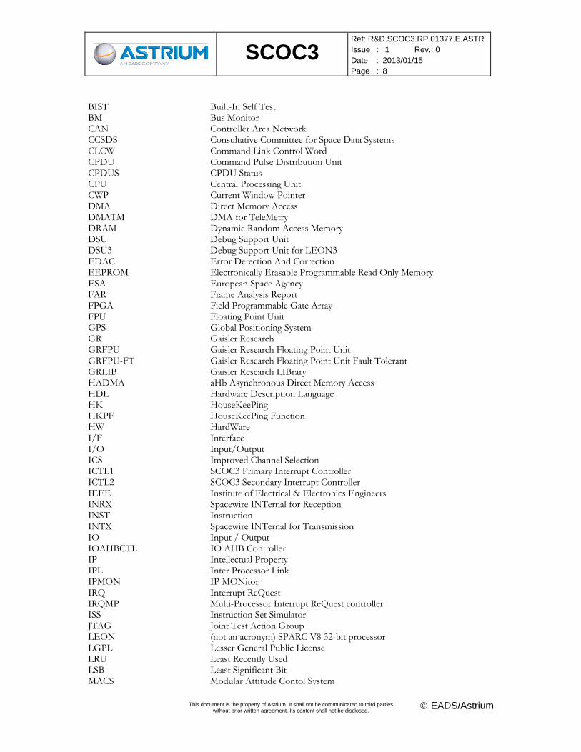
1.2 ACRONYMS
Name Description AHB Advanced High-performance Bus AHBR AHb to ahb BRidge AMBA Advanced Microcontroller Bus Architecture AOCS Attitude and Orbital Control System APB Advanced Peripheral Bus ASIC Application Specific Integrated Circuit ASSP Application Specific Standard Product ATPG Automatic Test Pattern Generation AUS AUthentication Status BC Bus Controller BCRT53 IP 1553 BC/RT/BM
SCOC3
Ref: R&D.SCOC3.RP.01377.E.ASTR Issue : 1 Rev.: 0 Date : 2013/01/15 Page : 8
This document is the property of Astrium. It shall not be communicated to third parties
without prior written agreement. Its content shall not be disclosed. EADS/Astrium
BIST Built-In Self Test BM Bus Monitor CAN Controller Area Network CCSDS Consultative Committee for Space Data Systems CLCW Command Link Control Word CPDU Command Pulse Distribution Unit CPDUS CPDU Status CPU Central Processing Unit CWP Current Window Pointer DMA Direct Memory Access DMATM DMA for TeleMetry DRAM Dynamic Random Access Memory DSU Debug Support Unit DSU3 Debug Support Unit for LEON3 EDAC Error Detection And Correction EEPROM Electronically Erasable Programmable Read Only Memory ESA European Space Agency FAR Frame Analysis Report FPGA Field Programmable Gate Array FPU Floating Point Unit GPS Global Positioning System GR Gaisler Research GRFPU Gaisler Research Floating Point Unit GRFPU-FT Gaisler Research Floating Point Unit Fault Tolerant GRLIB Gaisler Research LIBrary HADMA aHb Asynchronous Direct Memory Access HDL Hardware Description Language HK HouseKeePing HKPF HouseKeePing Function HW HardWare I/F Interface I/O Input/Output ICS Improved Channel Selection ICTL1 SCOC3 Primary Interrupt Controller ICTL2 SCOC3 Secondary Interrupt Controller IEEE Institute of Electrical & Electronics Engineers INRX Spacewire INTernal for Reception INST Instruction INTX Spacewire INTernal for Transmission IO Input / Output IOAHBCTL IO AHB Controller IP Intellectual Property IPL Inter Processor Link IPMON IP MONitor IRQ Interrupt ReQuest IRQMP Multi-Processor Interrupt ReQuest controller ISS Instruction Set Simulator JTAG Joint Test Action Group LEON (not an acronym) SPARC V8 32-bit processor LGPL Lesser General Public License LRU Least Recently Used LSB Least Significant Bit MACS Modular Attitude Contol System
SCOC3
Ref: R&D.SCOC3.RP.01377.E.ASTR Issue : 1 Rev.: 0 Date : 2013/01/15 Page : 9
This document is the property of Astrium. It shall not be communicated to third parties
without prior written agreement. Its content shall not be disclosed. EADS/Astrium
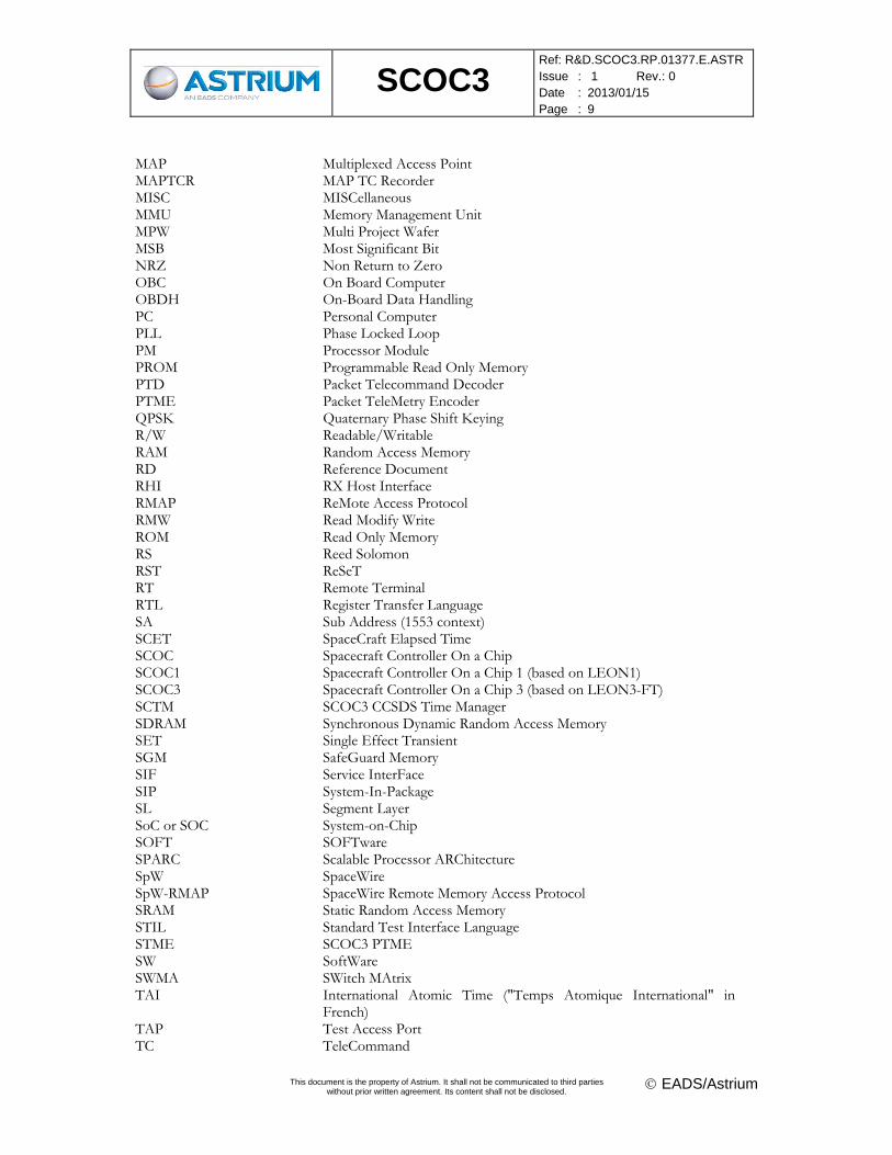
MAP Multiplexed Access Point MAPTCR MAP TC Recorder MISC MISCellaneous MMU Memory Management Unit MPW Multi Project Wafer MSB Most Significant Bit NRZ Non Return to Zero OBC On Board Computer OBDH On-Board Data Handling PC Personal Computer PLL Phase Locked Loop PM Processor Module PROM Programmable Read Only Memory PTD Packet Telecommand Decoder PTME Packet TeleMetry Encoder QPSK Quaternary Phase Shift Keying R/W Readable/Writable RAM Random Access Memory RD Reference Document RHI RX Host Interface RMAP ReMote Access Protocol RMW Read Modify Write ROM Read Only Memory RS Reed Solomon RST ReSeT RT Remote Terminal RTL Register Transfer Language SA Sub Address (1553 context) SCET SpaceCraft Elapsed Time SCOC Spacecraft Controller On a Chip SCOC1 Spacecraft Controller On a Chip 1 (based on LEON1) SCOC3 Spacecraft Controller On a Chip 3 (based on LEON3-FT) SCTM SCOC3 CCSDS Time Manager SDRAM Synchronous Dynamic Random Access Memory SET Single Effect Transient SGM SafeGuard Memory SIF Service InterFace SIP System-In-Package SL Segment Layer SoC or SOC System-on-Chip SOFT SOFTware SPARC Scalable Processor ARChitecture SpW SpaceWire SpW-RMAP SpaceWire Remote Memory Access Protocol SRAM Static Random Access Memory STIL Standard Test Interface Language STME SCOC3 PTME SW SoftWare SWMA SWitch MAtrix TAI International Atomic Time ("Temps Atomique International" in
French) TAP Test Access Port TC TeleCommand
SCOC3
Ref: R&D.SCOC3.RP.01377.E.ASTR Issue : 1 Rev.: 0 Date : 2013/01/15 Page : 10
This document is the property of Astrium. It shall not be communicated to third parties
without prior written agreement. Its content shall not be disclosed. EADS/Astrium
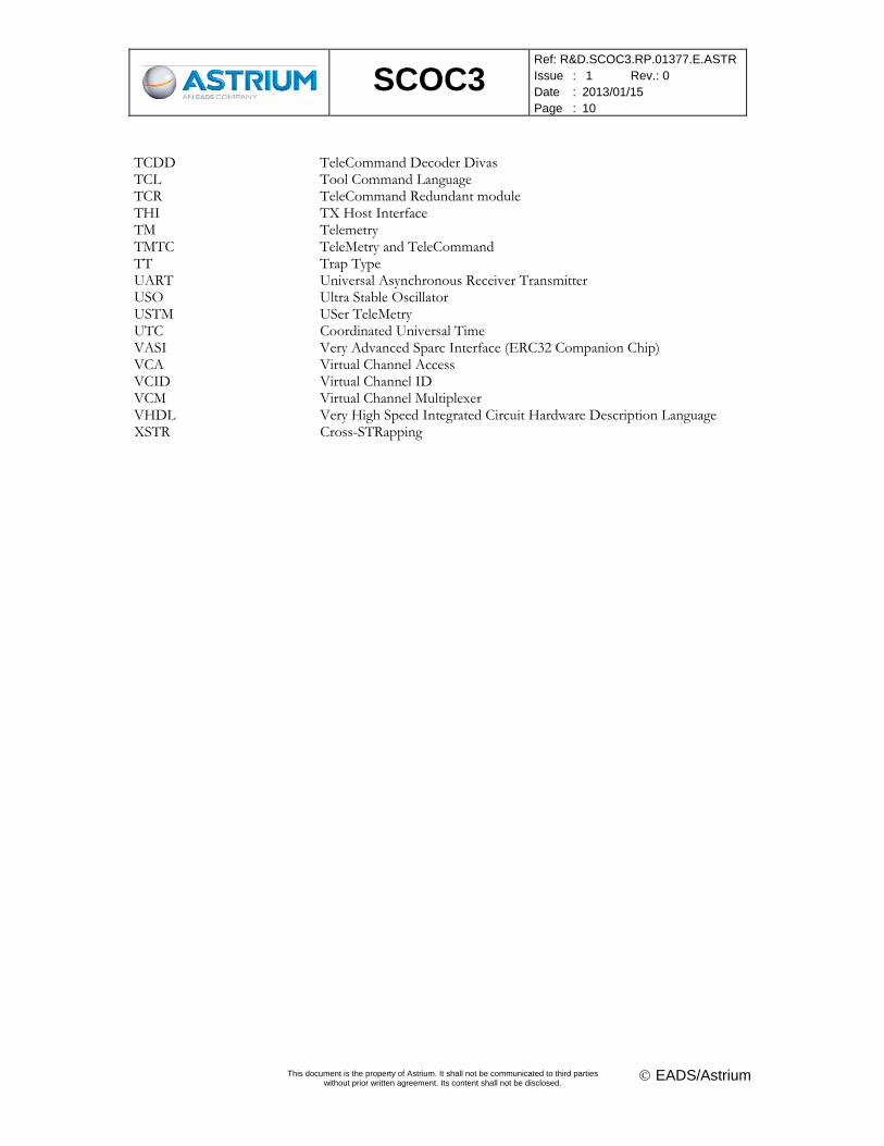
TCDD TeleCommand Decoder Divas TCL Tool Command Language TCR TeleCommand Redundant module THI TX Host Interface TM Telemetry TMTC TeleMetry and TeleCommand TT Trap Type UART Universal Asynchronous Receiver Transmitter USO Ultra Stable Oscillator USTM USer TeleMetry UTC Coordinated Universal Time VASI Very Advanced Sparc Interface (ERC32 Companion Chip) VCA Virtual Channel Access VCID Virtual Channel ID VCM Virtual Channel Multiplexer VHDL Very High Speed Integrated Circuit Hardware Description Language XSTR Cross-STRapping
SCOC3
Ref: R&D.SCOC3.RP.01377.E.ASTR Issue : 1 Rev.: 0 Date : 2013/01/15 Page : 11
This document is the property of Astrium. It shall not be communicated to third parties
without prior written agreement. Its content shall not be disclosed. EADS/Astrium
2 DESIGN OBJECTIVES AND CONSTRAINTS
2.1 BACKGROUND
The telecommunication satellite constellation market and the small satellite market drive to dramatically
decrease spacecraft equipment weight, consumption budget and recurrent price. The emerging micro
satellites and nano satellites generation also generates a demand for much more integrated equipments. In
the ‘80s and ‘90s, ESA and industrials developed a set of ASICs to reduce the size of electronics.
Functions such as the VCA, VCM and PTD used to build a CCSDS TM/TC system, bus interfaces such
as MACS, OBDH, 1553, or error correction chips (EDAC, Reed-Solomon, Viterbi…) were manufactured
as Application Specific Standard Products (ASSP).
In the past years, the ASICs developed under ESA contracts were offered to European industrials as
ASSPs. Most of these chips were designed using the VHDL language. As a side product, software macros
("IP-cores") were created, that can be reused under certain conditions. The idea of SCOC (Spacecraft
Controller On a Chip) was to merge several of these available blocks in a single ASIC called a “System-on-
Chip” that would be able to perform a large number of the Data Management System functions of a
platform.
With SCOC3, this idea has become reality, and the component is now available for space systems. Further
integration is possible with the SIP (System In a Package) emerging concept. Such a SIP device could also
include:
memories (SDRAM, SRAM, EEPROM, Flash…)
drivers (e.g. CAN, 1553…)
2.2 DESIGN OBJECTIVES
The System-on-Chip approach is now feasible as the number of gates per ASIC has grown enough. There
are at least two main domains of applications that require ASICs in Space, which are:
Digital Signal Processing applications that are extremely demanding in terms of gate and power
dissipation requirements. These functions are by now far from the “whole system on a single chip”
paradigm since they integrate hundreds of ASICs for some of them. Each of these individual ASICs
can however be a System-on-Chip by itself, i.e. integrating a processor core together with other
functions (DSP, communication, …).
Data Management Systems composed of elementary ASICs designed by the industrials or bought as
ASSP after their development under an ESA contract. These functions can be integrated together with
the microprocessor into a System-on-Chip to reduce the power and mass budget of on-board
computers.
Data Management Systems are built around a microprocessor, backplane bus interface, external serial bus
interfaces, TM/TC functions, positioning functions such as GPS... The first SCOC contract proved that it
was possible to integrate most of these functions on a single die. The objective of the SCOC series of
SCOC3
Ref: R&D.SCOC3.RP.01377.E.ASTR Issue : 1 Rev.: 0 Date : 2013/01/15 Page : 12
This document is the property of Astrium. It shall not be communicated to third parties
without prior written agreement. Its content shall not be disclosed. EADS/Astrium
activities was to produce an ASIC, available as an off-the-shelf component to the European Industry,
which simplifies the architecture of future on-board control and data handling (OBDH) systems.
SCOC3 functionality is comprehensive such as to satisfy a large variety of requirements, yet it is scalable
such as to be able to work in systems not using all of the features at reduced power consumption. As a key
asset, SCOC3 includes CCSDS telecommand and telemetry interface. While it has been demonstrated that
the reliability of an integrated solution is better than that of discrete components, SCOC3 nevertheless has
MAP- and other interfaces which allow cross-strapping of two redundant on-board computers. The use of
cache was a main concern for real time software developers. Most internal studies in this domain lead to a
solution satisfying both hardware and software teams.
The SCOC3 System-on-Chip resulting from this activity is a radiation-hardened ASIC providing all the
features of a spacecraft control system:
A LEON3-FT SPARC V8 processor including a debug module (DSU), a high-performance FPU (GRFPU), large caches (2 * 64kB) and a MMU
A CCSDS TC decoder
A CCSDS TM encoder
A CCSDS Time Management controller
8 * SpaceWire controllers, 2 of them being multiplexed and 7 of them supporting the RMAP protocol in HW
2 * 1553 BC/BM/RT controllers (each exclusive with the CAN controller that shares pins)
2 * CAN controllers (each exclusive with the 1553 controller that shares pins)
4 * UART controllers (3 * APB UART and 1 * AHB UART)
2 * memory controllers (One dedicated to CPU and one dedicated to the IO and TMTC modules)
A Housekeeping module
An AHB bus monitoring module
MAP interfaces to cross-strap two SCOC3s
Power-reduction modes
SCOC3
Ref: R&D.SCOC3.RP.01377.E.ASTR Issue : 1 Rev.: 0 Date : 2013/01/15 Page : 13
This document is the property of Astrium. It shall not be communicated to third parties
without prior written agreement. Its content shall not be disclosed. EADS/Astrium
3 MAIN TOPICS
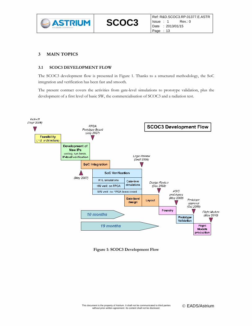
3.1 SCOC3 DEVELOPMENT FLOW
The SCOC3 development flow is presented in Figure 1. Thanks to a structured methodology, the SoC
integration and verification has been fast and smooth.
The present contract covers the activities from gate-level simulations to prototype validation, plus the
development of a first level of basic SW, the commercialisation of SCOC3 and a radiation test.
Figure 1: SCOC3 Development Flow
SCOC3
Ref: R&D.SCOC3.RP.01377.E.ASTR Issue : 1 Rev.: 0 Date : 2013/01/15 Page : 14
This document is the property of Astrium. It shall not be communicated to third parties
without prior written agreement. Its content shall not be disclosed. EADS/Astrium
3.2 GATE-LEVEL DESIGN
Gate-level design, also termed detailed design in ECSS-Q60-02A, was composed of the following
activities:
SCOC3 synthesis & static timing analysis
SCOC3 gate-level simulations
SCOC3 formal proof
SCOC3 preliminary floorplan
SCOC3 foundry test programs
3.2.1 SCOC3 synthesis and static timing analysis
The synthesis of SCOC3 has been performed using Synopsys DC compiler. DC Ultra and the required
DesignWare libraries have been evaluated. But it appeared that the gain in performance was less than 5%.
DC Topo was not used because its support was too recent for the targeted technology. The synthesis of
SCOC3 took about 4 hours on a UNIX workstation which was acceptable since most of the syntheses
were carried out during the night. This duration included JTAG and scan insertion that were quite long.
LEON3FT was provided by Gaisler Research as a pre-synthesized netlist, therefore the exploration of the
configuration space was limited since each new configuration of the generic parameters required a new
synthesis and delivery by Gaisler Research. This could also have been a limiting factor when evaluating the
other versions of DC compiler.
Concerning SEU hardening, all the flip-flops are HDFF SEU hardened flip-flops provided in ATMEL
library. A single clock tree is used (the clock tree is not triplicated) what simplifies gate level design.
A verilog netlist is created by the synthesis and the SDF file is generated using Primetime, in best and
worst conditions.
The static timing analysis was performed using Synopsys PrimeTime. Procedures have been developed to
check the timings in functional mode, scan mode and JTAG mode. These checks are carried out in best
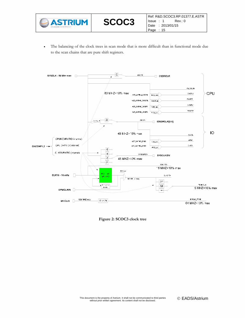
and worst conditions. SCOC3 is able to work at many frequencies for the CPU clock and the IO clock.
Thus the timing analysis is made for each clock configuration: (CPU, IO clock) = (32,32), (48,32),
(64,32)… At this step the exact characteristics of the clock tree are unknown. The clock tree is modelled
by ideal buffers. The value of these buffers have been chosen following ATMEL recommendations, that
consists in a table giving the estimated delay with respect to the number of flip flops of the tree, and the
die size. A drawing of the clock tree is provided in Figure 2. The main difficulties of such a clock tree are:
The different clock frequencies that are statically programmable and that require either a direct
connection or a divide-by-2 flip-flop for generation. It introduces a latency that ATMEL has to
compensate for.
SCOC3
Ref: R&D.SCOC3.RP.01377.E.ASTR Issue : 1 Rev.: 0 Date : 2013/01/15 Page : 15
This document is the property of Astrium. It shall not be communicated to third parties
without prior written agreement. Its content shall not be disclosed. EADS/Astrium
The balancing of the clock trees in scan mode that is more difficult than in functional mode due
to the scan chains that are pure shift registers.
Figure 2: SCOC3 clock tree
SCOC3
Ref: R&D.SCOC3.RP.01377.E.ASTR Issue : 1 Rev.: 0 Date : 2013/01/15 Page : 16
This document is the property of Astrium. It shall not be communicated to third parties
without prior written agreement. Its content shall not be disclosed. EADS/Astrium
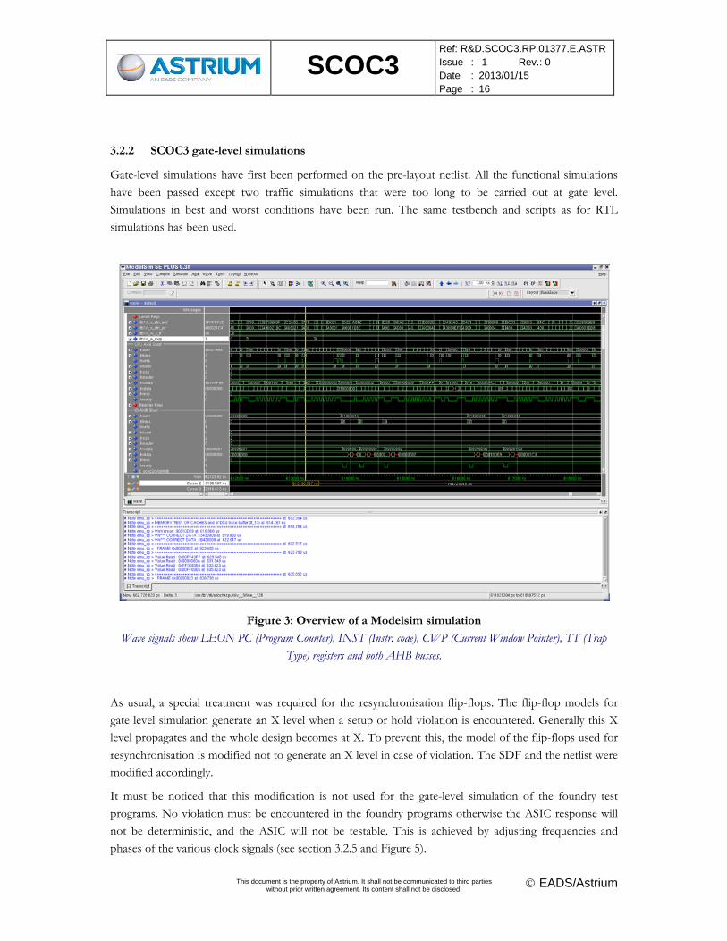
3.2.2 SCOC3 gate-level simulations
Gate-level simulations have first been performed on the pre-layout netlist. All the functional simulations
have been passed except two traffic simulations that were too long to be carried out at gate level.
Simulations in best and worst conditions have been run. The same testbench and scripts as for RTL
simulations has been used.
Figure 3: Overview of a Modelsim simulation
Wave signals show LEON PC (Program Counter), INST (Instr. code), CWP (Current Window Pointer), TT (Trap
Type) registers and both AHB busses.
As usual, a special treatment was required for the resynchronisation flip-flops. The flip-flop models for
gate level simulation generate an X level when a setup or hold violation is encountered. Generally this X
level propagates and the whole design becomes at X. To prevent this, the model of the flip-flops used for
resynchronisation is modified not to generate an X level in case of violation. The SDF and the netlist were
modified accordingly.
It must be noticed that this modification is not used for the gate-level simulation of the foundry test
programs. No violation must be encountered in the foundry programs otherwise the ASIC response will
not be deterministic, and the ASIC will not be testable. This is achieved by adjusting frequencies and
phases of the various clock signals (see section 3.2.5 and Figure 5).
SCOC3
Ref: R&D.SCOC3.RP.01377.E.ASTR Issue : 1 Rev.: 0 Date : 2013/01/15 Page : 17
This document is the property of Astrium. It shall not be communicated to third parties
without prior written agreement. Its content shall not be disclosed. EADS/Astrium
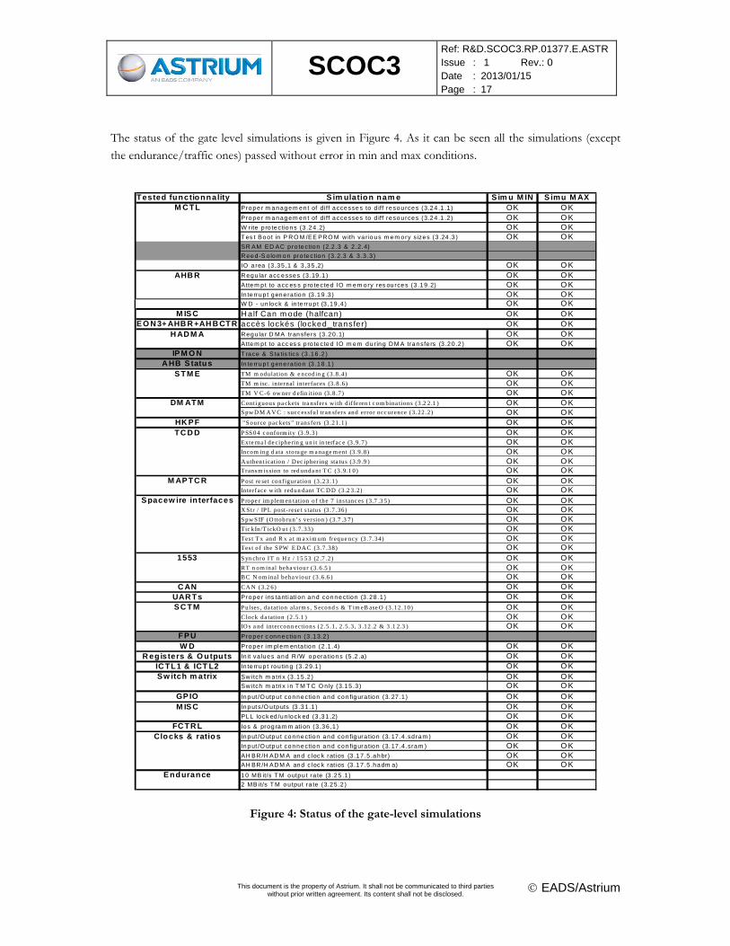
The status of the gate level simulations is given in Figure 4. As it can be seen all the simulations (except
the endurance/traffic ones) passed without error in min and max conditions.
Tested functionnality S im ulation nam e S im u M IN S imu M AX
M C TL Prope r m anagem en t of di ff accesses to d iff resou rces (3.24 .1 .1 ) OK O KPrope r m anagem en t of di ff accesses to d iff resou rces (3.24 .1 .2 ) OK O KW rite p ro tections (3 .24 .2) OK O KT es t Boo t in P R O M /EE PRO M w ith va r ious m em ory sizes (3 .24 .3 ) OK O KSR AM ED AC p ro tection (2.2 .3 & 2 .2. 4)
R eed -S o lom on pro tection (3 .2.3 & 3 .3 .3 )
IO a rea (3 ,35 ,1 & 3 ,35 ,2) OK O KAHB R R egu la r acc esses (3 .19 .1 ) OK O K
Attem p t to acc es s p ro tected IO m em ory res ou rces (3 .19 .2) OK O KIn te rrup t gene ra tion (3 .19 .3 ) OK O KW D - un lock & in te rrup t (3 ,19 ,4 ) OK O K
M IS C H alf Can m ode (halfcan) OK O KLE O N 3+ AHB R +AH B CTR accès lockés (locked_transfer) OK O K
H AD M A R egu la r D MA transfe rs (3 .20 .1) OK O KAttem p t to acc es s p ro tected IO m em du r ing D M A transfe rs (3 .20 .2 ) OK O K
IP M O N T race & Sta tis tics (3 .16 .2 )
A HB S tatus In te rrup t gene ra tion (3 .18 .1 )
S TM E TM m odulation & e ncodin g (3.8 .4) OK O KTM m isc. internal interfaces (3.8.6) OK O KTM V C-6 ow ner d efin ition (3 .8 .7) OK O K
DM ATM Conti guous pa ckets tra nsfers w ith dif fe ren t c om bina tions (3.2 2 .1 ) OK O KS pw D M A V C : s ucc es sful tran sfers and error occ urence (3.22 .2) OK O K
HK PF "S ource pac kets " trans fers (3 .21 .1) OK O KTC D D P SS 04 c onform ity (3 .9 .3) OK O K
Exte rna l de ciphe rin g un it in terfac e (3 .9 .7) OK O KIncom ing d ata s tora ge m a nage m ent (3.9 .8) OK O KA uthent ication / D ec ipher ing sta tus (3 .9 .9 ) OK O KTrans m is sion to red unda nt T C (3.9.1 0) OK O K
M APTC R P ost re set conf iguration (3 .23 .1) OK O KIn terface w ith redun dant TC D D (3 .2 3.2) OK O K
Spacew ire in terfaces P rope r im plem en tation of the 7 ins tanc es (3 .7 .3 5) OK O KX S tr / IP L post-rese t s tatus (3 .7.36) OK O KS pw S IF (O ttobrun’s version ) (3 .7 .3 7) OK O KTic kIn/T ickO ut (3 .7 .33) OK O KTes t T x and R x a t m a xim um freque ncy (3 .7 .34) OK O KTes t of the S PW E D A C (3 .7 .38) OK O K
1553 S yn chro IT n H z / 15 53 (2 .7 .2) OK O KRT n om inal beha viour (3 .6 .5 ) OK O KBC N om inal beha viour (3.6.6 ) OK O K
C AN CA N (3.2 6) OK O KUAR Ts Prope r i ns tantiati on and connection (3 .28 .1 ) OK O KSC TM P ulses , da tation alarm s , S econd s & T im eB ase O (3.12 .10) OK O K
Clock da tation (2 .5 .1 ) OK O KIO s a nd interconn ections (2 .5 .1, 2 .5 .3 , 3 .12 .2 & 3 .1 2 .3 ) OK O K
FPU Prope r c onnection (3 .13.2 )
W D Prope r im plem en ta tion (2 .1 .4) OK O KR egisters & O utputs In it va lues and R /W opera tions (5 .2 .a) OK O K
IC TL1 & ICT L2 In te rrup t rou ting (3 .29.1 ) OK O KSw itch m atrix Sw i tch m a trix (3 .15 .2 ) OK O K
Sw i tch m a trix in T M T C O n ly (3.15 .3 ) OK O KGP IO Input /O utpu t connection and con figura tion (3. 27 .1 ) OK O KM IS C Input s /O u tputs (3 .31 .1 ) OK O K
PLL lock ed /un lock ed (3 ,31 ,2) OK O KFC TR L Ios & prog ram m ation (3 ,36 ,1 ) OK O K
Clocks & ratios Input /O utpu t connection and con figura tion (3. 17 .4 .sd ram ) OK O KInput /O utpu t connection and con figura tion (3. 17 .4 .sram ) OK O KAH BR /H ADM A and c loc k rati os (3 .17 .5 .ahbr) OK O KAH BR /H ADM A and c loc k rati os (3 .17 .5 .hadm a) OK O K
Endurance 10 MB it/s T M outpu t ra te (3 .25 .1 )
2 MB it/s T M ou tpu t ra te (3.25 .2 )
Figure 4: Status of the gate-level simulations
SCOC3
Ref: R&D.SCOC3.RP.01377.E.ASTR Issue : 1 Rev.: 0 Date : 2013/01/15 Page : 18
This document is the property of Astrium. It shall not be communicated to third parties
without prior written agreement. Its content shall not be disclosed. EADS/Astrium
3.2.3 SCOC3 formal proof
To confirm and secure the results of the gate-level simulations, a formal proof of SCOC3 has been
performed with the FormalPro tool from Mentor. LEON3-FT was not included in the check since it was
provided as a netlist. The modules that are coded “classically” were checked without problem. But the tool
had some difficulties with modules using complex VHDL structures, such as the PTME module that
largely uses generics and records.
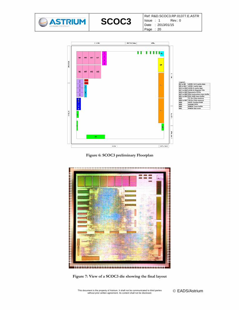
3.2.4 SCOC3 preliminary floorplan
The SCOC3 preliminary floorplan has been defined by Astrium (see Figure 6). Coloured boxes represent
the memory blocks that are placed on the die. Their location has been defined depending on the pads. The
figure depicts the location proposed by Astrium. ATMEL had the possibility to translate, flip or rotate
them. No floorplan of each function was required by ATMEL. Only LEON was placed by ATMEL in a
given area. The 8 larger pink blocks are the LEON3 cache memories. The two orange blocks are the TM
memories and the yellow one beside is the TC memory. It has been verified that the empty space left on
the die by memories is largely sufficient to contain the SCOC3 gates with the recommended security
factor. The JTAG circuitry is placed by ATMEL around the chip, an empty space is left between
memories and the pads.
3.2.5 SCOC3 foundry test programs
Foundry test programs have been developed for SCOC3. These programs correspond to 4 categories:
The functional test programs
The JTAG test program
The BIST test programs
The ATPG test programs
32 test programs have thus been developed. The total number of vectors is about 14 million which is
almost the limit given by ATMEL (16 M vectors). Such a number of vectors should guarantee the quality
of the tested parts.
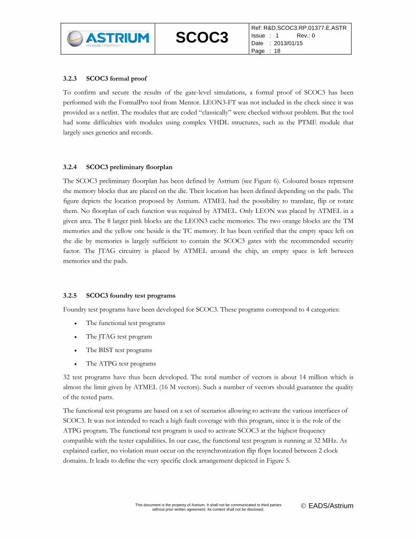
The functional test programs are based on a set of scenarios allowing to activate the various interfaces of
SCOC3. It was not intended to reach a high fault coverage with this program, since it is the role of the
ATPG program. The functional test program is used to activate SCOC3 at the highest frequency
compatible with the tester capabilities. In our case, the functional test program is running at 32 MHz. As
explained earlier, no violation must occur on the resynchronization flip flops located between 2 clock
domains. It leads to define the very specific clock arrangement depicted in Figure 5.
SCOC3
Ref: R&D.SCOC3.RP.01377.E.ASTR Issue : 1 Rev.: 0 Date : 2013/01/15 Page : 19
This document is the property of Astrium. It shall not be communicated to third parties
without prior written agreement. Its content shall not be disclosed. EADS/Astrium
CPUCLK (internal), before layout (estimate)
31,25 ns
32 MHz
SYSCLK
10 ns
10 ns
3 ns
11,5 ns = 3 + 8,5 ns clock tree + pad
CPUIO (internal), before layout (estimate) 18,5 ns
SPWCLKIN 19 ns
5 ns
4,2 ns = clock tree + pad
SPWCLKTX (internal), before layout (estimate)
Input setting at T=0 Output sampling at T=31 ns
SPWRX input
3 ns
CLK16
BITCLKI
2 ns
2 nsBITCLKDIV (internal) before layout (estimate)
4 ns
SPWRX internal, before layout (estimate)
CLK16 internal, before layout (estimate)
Figure 5: Clock definition for the functional foundry test program
The JTAG test program activates all the states of the TAP controller. It captures the inputs and forces the
outputs. It must be avoided that all the outputs are switching simultaneously, otherwise supply problem
may be encountered on ATMEL tester.
The BIST test program is used to activate the self test of each memory block and to verify that no errors
are found during the memory test.
The ATPG program is generated by Tetramax from Synopsys. Its fault coverage is 97.42% which is a
beyond the 95% required by Atmel. Transition delay fault (TDF-ATPG) was not used. The test program is
generated in STIL format, and interface between STIL and the tester is custom-developed by Atmel. In
the past, the transfer to tester had not always been smooth, but for SCOC3, no problems were
encountered.
3.3 LAYOUT AND MANUFACTURING
The layout and manufacturing of the SCOC3 ASIC have been performed by ATMEL.
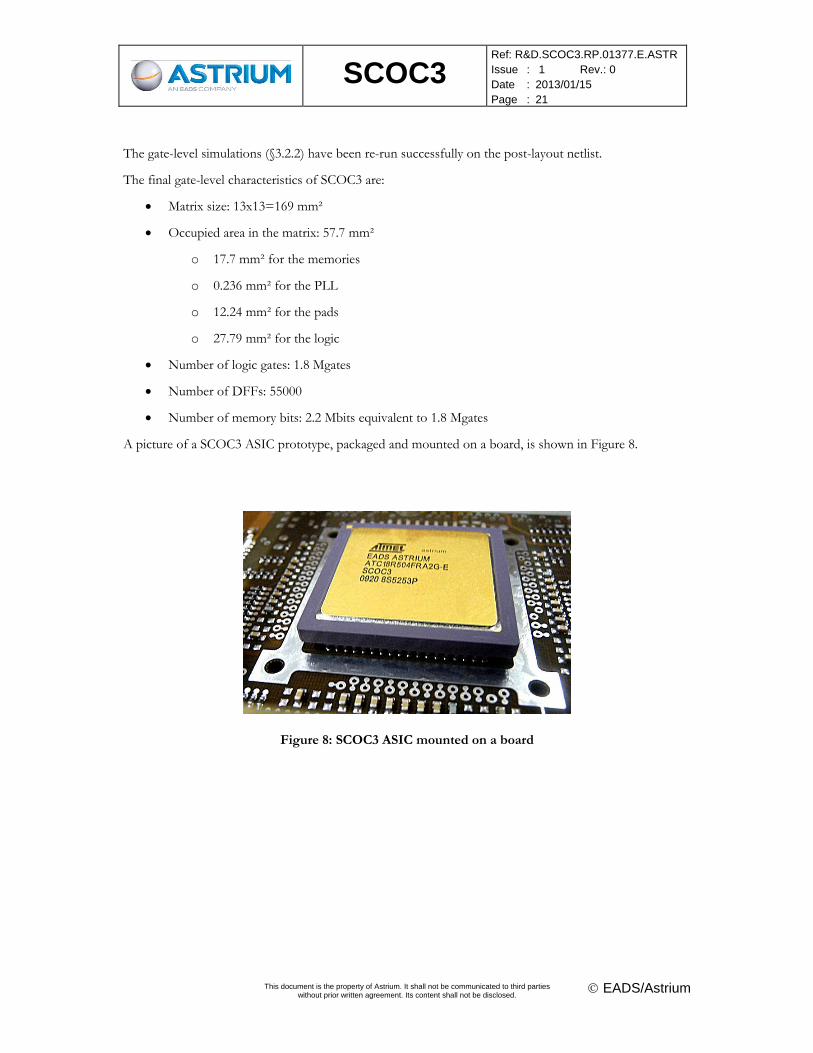
The final layout is shown in Figure 7. ATMEL has optimized the memory floorplan proposed by Astrium.
In particular, since the critical path is located in the LEON3FT, between the integer unit and the caches,
ATMEL has performed a hierarchical layout, with LEON3FT enclosed in a square area in the top left of
the die, surrounded by its memories.
SCOC3
Ref: R&D.SCOC3.RP.01377.E.ASTR Issue : 1 Rev.: 0 Date : 2013/01/15 Page : 20
This document is the property of Astrium. It shall not be communicated to third parties
without prior written agreement. Its content shall not be disclosed. EADS/Astrium
M9
M10
M11
M12
M13
M14
M15
M16
M17
M18
1
Legend :M1 to M8 LEON I & D cache dataM9 to M12 LEON I cache tagsM13 to M16 LEON D cache tagsM17 to M18 LEON IU Register FileM19 to M25 Spacewire FIFOsM47 to M50 DSU Instruction trace bufferM51 to M54 DSU AHB trace bufferM55 TC On Chip memoryM56 to M57 TM On Chip memoryM58 HKPF Context RAMM59 HADMA FIFOM60 IPMON Trace bufferM61 IPMON Stat mem
Figure 6: SCOC3 preliminary Floorplan
Figure 7: View of a SCOC3 die showing the final layout
SCOC3
Ref: R&D.SCOC3.RP.01377.E.ASTR Issue : 1 Rev.: 0 Date : 2013/01/15 Page : 21
This document is the property of Astrium. It shall not be communicated to third parties
without prior written agreement. Its content shall not be disclosed. EADS/Astrium
The gate-level simulations (§3.2.2) have been re-run successfully on the post-layout netlist.
The final gate-level characteristics of SCOC3 are:
Matrix size: 13x13=169 mm²
Occupied area in the matrix: 57.7 mm²
o 17.7 mm² for the memories
o 0.236 mm² for the PLL
o 12.24 mm² for the pads
o 27.79 mm² for the logic
Number of logic gates: 1.8 Mgates
Number of DFFs: 55000
Number of memory bits: 2.2 Mbits equivalent to 1.8 Mgates
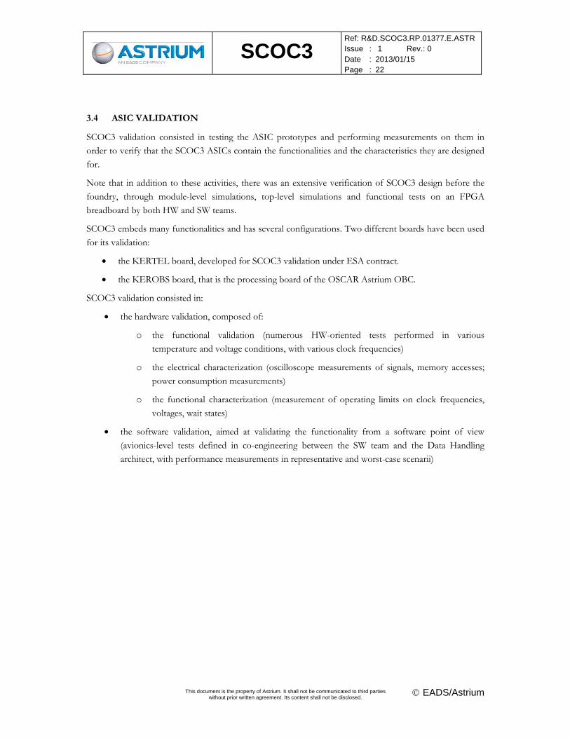
A picture of a SCOC3 ASIC prototype, packaged and mounted on a board, is shown in Figure 8.
Figure 8: SCOC3 ASIC mounted on a board
SCOC3
Ref: R&D.SCOC3.RP.01377.E.ASTR Issue : 1 Rev.: 0 Date : 2013/01/15 Page : 22
This document is the property of Astrium. It shall not be communicated to third parties
without prior written agreement. Its content shall not be disclosed. EADS/Astrium
3.4 ASIC VALIDATION
SCOC3 validation consisted in testing the ASIC prototypes and performing measurements on them in
order to verify that the SCOC3 ASICs contain the functionalities and the characteristics they are designed
for.
Note that in addition to these activities, there was an extensive verification of SCOC3 design before the
foundry, through module-level simulations, top-level simulations and functional tests on an FPGA
breadboard by both HW and SW teams.
SCOC3 embeds many functionalities and has several configurations. Two different boards have been used
for its validation:
the KERTEL board, developed for SCOC3 validation under ESA contract.
the KEROBS board, that is the processing board of the OSCAR Astrium OBC.
SCOC3 validation consisted in:
the hardware validation, composed of:
o the functional validation (numerous HW-oriented tests performed in various
temperature and voltage conditions, with various clock frequencies)
o the electrical characterization (oscilloscope measurements of signals, memory accesses;
power consumption measurements)
o the functional characterization (measurement of operating limits on clock frequencies,
voltages, wait states)
the software validation, aimed at validating the functionality from a software point of view
(avionics-level tests defined in co-engineering between the SW team and the Data Handling
architect, with performance measurements in representative and worst-case scenarii)
SCOC3
Ref: R&D.SCOC3.RP.01377.E.ASTR Issue : 1 Rev.: 0 Date : 2013/01/15 Page : 23
This document is the property of Astrium. It shall not be communicated to third parties
without prior written agreement. Its content shall not be disclosed. EADS/Astrium
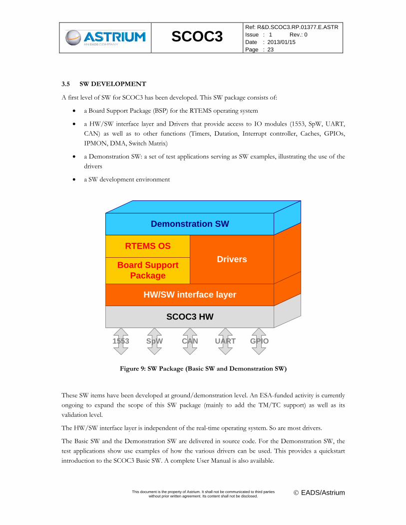
3.5 SW DEVELOPMENT
A first level of SW for SCOC3 has been developed. This SW package consists of:
a Board Support Package (BSP) for the RTEMS operating system
a HW/SW interface layer and Drivers that provide access to IO modules (1553, SpW, UART,
CAN) as well as to other functions (Timers, Datation, Interrupt controller, Caches, GPIOs,
IPMON, DMA, Switch Matrix)
a Demonstration SW: a set of test applications serving as SW examples, illustrating the use of the
drivers
a SW development environment
SCOC3 HW
HW/SW interface layer
Board Support Package
RTEMS OS
Drivers
Demonstration SW
1553 SpW CAN UART GPIO
Figure 9: SW Package (Basic SW and Demonstration SW)
These SW items have been developed at ground/demonstration level. An ESA-funded activity is currently
ongoing to expand the scope of this SW package (mainly to add the TM/TC support) as well as its
validation level.
The HW/SW interface layer is independent of the real-time operating system. So are most drivers.
The Basic SW and the Demonstration SW are delivered in source code. For the Demonstration SW, the
test applications show use examples of how the various drivers can be used. This provides a quickstart
introduction to the SCOC3 Basic SW. A complete User Manual is also available.
SCOC3
Ref: R&D.SCOC3.RP.01377.E.ASTR Issue : 1 Rev.: 0 Date : 2013/01/15 Page : 24
This document is the property of Astrium. It shall not be communicated to third parties
without prior written agreement. Its content shall not be disclosed. EADS/Astrium
The SW development environment comprises a compiler, a linker, and a tool to communicate with
SCOC3. It is delivered in a virtual machine, containing a Linux installation with all the tools properly
installed and configured. This virtual machine can be quickly installed on most platforms, providing a
quick way to install the environment without portability, version compatibility or tool installation
problems.
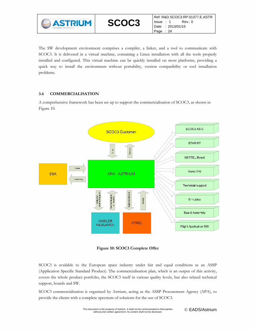
3.6 COMMERCIALISATION
A comprehensive framework has been set up to support the commercialisation of SCOC3, as shown in
Figure 10.
Figure 10: SCOC3 Complete Offer
SCOC3 is available to the European space industry under fair and equal conditions as an ASSP
(Application Specific Standard Product). The commercialisation plan, which is an output of this activity,
covers the whole product portfolio, the SCOC3 itself in various quality levels, but also related technical
support, boards and SW.
SCOC3 commercialisation is organized by Astrium, acting as the ASSP Procurement Agency (APA), to
provide the clients with a complete spectrum of solutions for the use of SCOC3.
SCOC3
Ref: R&D.SCOC3.RP.01377.E.ASTR Issue : 1 Rev.: 0 Date : 2013/01/15 Page : 25
This document is the property of Astrium. It shall not be communicated to third parties
without prior written agreement. Its content shall not be disclosed. EADS/Astrium
SCOC3 is advertised at the www.scoc3.com website, at which a contact address is provided. User
documentation and quotations for SCOC3 parts and related products can be requested via this contact.
SCOC3 is proposed at 3 quality levels (EM/prototype, QML-Q or QML-V). Since Atmel has refused to
endorse SCOC3 as an ASSP, ATMEL applies Minimum Order Quantities (MOQ). Therefore, SCOC3, for
the time being, can be ordered only with MOQ of 15 for EM, 20 for QML-Q and 15 for QML-V.
Discussions have started with ESA to circumvent the MOQ for the final customer by funding an initial
stock of components to be dispatched by Astrium in small quantities.
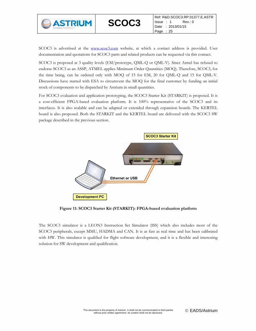
For SCOC3 evaluation and application prototyping, the SCOC3 Starter Kit (STARKIT) is proposed. It is
a cost-efficient FPGA-based evaluation platform. It is 100% representative of the SCOC3 and its
interfaces. It is also scalable and can be adapted or extended through expansion boards. The KERTEL
board is also proposed. Both the STARKIT and the KERTEL board are delivered with the SCOC3 SW
package described in the previous section.
Figure 11: SCOC3 Starter Kit (STARKIT): FPGA-based evaluation platform
The SCOC3 simulator is a LEON3 Instruction Set Simulator (ISS) which also includes most of the
SCOC3 peripherals, except MMU, HADMA and CAN. It is as fast as real time and has been calibrated
with HW. This simulator is qualified for flight software development, and it is a flexible and interesting
solution for SW development and qualification.
SCOC3
Ref: R&D.SCOC3.RP.01377.E.ASTR Issue : 1 Rev.: 0 Date : 2013/01/15 Page : 26
This document is the property of Astrium. It shall not be communicated to third parties
without prior written agreement. Its content shall not be disclosed. EADS/Astrium
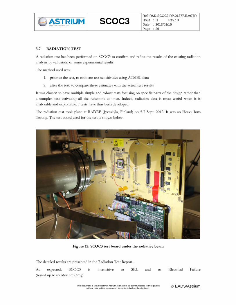
3.7 RADIATION TEST
A radiation test has been performed on SCOC3 to confirm and refine the results of the existing radiation
analysis by validation of some experimental results.
The method used was:
1. prior to the test, to estimate test sensitivities using ATMEL data
2. after the test, to compare these estimates with the actual test results
It was chosen to have multiple simple and robust tests focusing on specific parts of the design rather than
a complex test activating all the functions at once. Indeed, radiation data is most useful when it is
analyzable and exploitable. 7 tests have thus been developed.
The radiation test took place at RADEF (Jyvaskyla, Finland) on 5-7 Sept. 2012. It was an Heavy Ions
Testing. The test board used for the test is shown below.
Figure 12: SCOC3 test board under the radiative beam
The detailed results are presented in the Radiation Test Report.
As expected, SCOC3 is insensitive to SEL and to Electrical Failure
(tested up to 65 Mev.cm2/mg).
SCOC3
Ref: R&D.SCOC3.RP.01377.E.ASTR Issue : 1 Rev.: 0 Date : 2013/01/15 Page : 27
This document is the property of Astrium. It shall not be communicated to third parties
without prior written agreement. Its content shall not be disclosed. EADS/Astrium
The actual SEU rates, resulting from the test, are also lower than the rates estimated prior to the test. This
is detailed in the Radiation Test Report.
4 FOLLOW-UP ACTIVITIES
A SW activity is currently undertaken by a SW house, with ESA support, to expand the scope of the
current Basic SW as well as its validation level.
SCOC3
Ref: R&D.SCOC3.RP.01377.E.ASTR Issue : 1 Rev.: 0 Date : 2013/01/15 Page : 28
This document is the property of Astrium. It shall not be communicated to third parties
without prior written agreement. Its content shall not be disclosed. EADS/Astrium
5 CONCLUSION
The result of the SCOC series of activities is a powerful processor and spacecraft controller, in the form of
a highly integrated System-on-Chip, SCOC3. This ASIC greatly reduces cost, power and mass of on-board
computers.
SCOC3 is fully validated and already selected for 8 satellites. SCOC3 is flight-proven since 9th September
2012 on the SPOT6 satellite.
SCOC3 is also commercially available, with a comprehensive package to support its integration, use and
SW development.
This study also demonstrates the necessity for a reliable and effective design methodology for System-on-
Chip development. A good methodology allowed speeding up the development of the large and complex
design of SCOC3. There is a great interest for this SoC methodology for the future development of highly
integrated ASICs, whether they integrate CPU cores or not.
The development of large SoC devices also relies on the availability of a library of validated IP cores. Some
of these cores were provided by ESA, as the PTME, the Spacewire IP, the HurriCAN controller and a
collection of small but indispensable IP. The main processing function was procured as a commercial IP
from Gaisler Research: GRLIB and LEON3-FT.
The methodology also takes advantage from standards coming from commercial applications, military
developments or space industry, such as AMBA busses for internal connections of the IP cores, and also
external interface standards, that allow the reuse of developed IP cores, Mil-Std-1553, Spacewire, CCSDS
TM/TC. This strategy was beneficial for SCOC3 development as it allowed reusing previously developed
validation tools (emulators for the simulations and standard hardware testbenches for the board
evaluation).
The consistent use of these standards in space (ESA) programmes should be promoted, and the catalogue
of available IP cores should be enhanced accordingly.
The availability of large commercial programmable logic devices is beneficial. They allow rapid prototyping
of the system and a deeper functional validation than using only simulations. FPGA prototyping also
provides a breadboard platform for early software development, well before the availability of the System-
On-ASIC.
The development of a prototyping hardware platform does not suppress the essential simulation phase.
Nevertheless, due to the complexity of SCOC3, the simulation time dramatically increases (while partially
compensated by the increase of the computational performance of the simulation platform). The
simulations are then used to fully verify the IP core functionality in a standalone mode, while the system
simulations only partially verify the core functionality of each IP, focusing on the correct integration of
SCOC3. But it has to be noticed that an extensive set of simulations has been used in order to increase
confidence and allow early bug detection/investigation.
SCOC3
Ref: R&D.SCOC3.RP.01377.E.ASTR Issue : 1 Rev.: 0 Date : 2013/01/15 Page : 29
This document is the property of Astrium. It shall not be communicated to third parties
without prior written agreement. Its content shall not be disclosed. EADS/Astrium
It is always difficult to estimate the real feasibility of such an ASIC due to the margins taken at each level
(system, design, foundry). In the end, SCOC3 uses less resources than predicted. This reduces power
consumption and avoids problems during the layout phase.
For such complex designs, the use of formal proof for equivalence checking is mandatory.
Finally, the development of a Basic SW and of a complete set of utilities and services (SW Simulator, low-
cost FPGA platform, technical support) is essential to support the use of a System-on-Chip.
SCOC3
Ref: R&D.SCOC3.RP.01377.E.ASTR Issue : 1 Rev.: 0 Date : 2013/01/15 Page : 30
This document is the property of Astrium. It shall not be communicated to third parties
without prior written agreement. Its content shall not be disclosed. EADS/Astrium
DISTRIBUTION LIST
Overall document Summary Action Information
Roland Weigand (ESA) X
Mathieu Vandenbossche X
Franck Koebel X
Marc Souyri X
Arnaud Wagner X
Jean-Marc Taine X
Rémi Cissou X
Jean-Jacques Derrien X
Jean-Paul Blanche X
Alexandre Mège X
Aurélien Lefèvre X