Embed Size (px)
DESCRIPTION
System
Citation preview

STORMWATER CONVEYANCE MODELING AND DESIGN
Authors
Haestad Methods
S. Rocky Durrans
Managing Editor
Kristen Dietrich
Contributing Authors
Muneef Ahmad, Thomas E. Barnard,
Peder Hjorth, and Robert Pitt
Peer Review Board
Roger T. Kilgore (Kilgore Consulting)
G. V. Loganathan (Virginia Tech)
Michael Meadows (University of South Carolina)
Shane Parson (Anderson & Associates)
David Wall (University of New Haven)
Editors
David Klotz, Adam Strafaci, and Colleen Totz
HAESTAD PRESS
Waterbury, CT USA
Click here to visit the Bentley Institute Press Web page for more information

C H A P T E R
2System Components, Models,and the Design Process
Stormwater is managed with a network of structures designed to collect, convey, detain, treat, and discharge runoff. Examples of these structures are storm sewer con-duits, culverts, drainage ditches, and detention ponds. Generally, these structures act in a passive mode, relying on the force of gravity to move water. Occasionally, how-ever, stormwater is actively managed with devices such as pumps, gates, or valves.
In this book, models are defined as representations of the physical behavior of hydro-logic and/or hydraulic systems. They may be physical, electric-analog, or mathemati-cal in nature. Mathematical models are based on the laws of physics and typically apply the principles of conservation of mass, energy, or momentum. Computer mod-els (such as those on the CD-ROM accompanying this book) are collections of automated mathematical models.
Models are used to predict how stormwater structures will perform. The basic elements that must be considered when modeling stormwater management systems are hydrology (specifically, watershed response to storms), hydraulic capacities of the system structures, and upstream and downstream impacts (such as the effect of tailwa-ter elevation on storm sewer system hydraulics or the effect of a storm sewer system on downstream discharges).
Engineers use models in the design process to simulate the performance of a stormwater collection and conveyance system under a range of flows and conditions. The tradeoffs between size and performance can then be evaluated. Hydraulic performance in terms of resulting flows, headwater elevations, exit velocities, and so forth is the primary focus of this text. Other factors that must be considered in selecting system components are construction cost, structural loads, maintenance requirements, aesthetics, seepage flow (from or into the groundwater), and biological habitat. The final design is based on compliance with regulations, standards, and,ultimately, the professional judgment of the engineer.

18 System Components, Models, and the Design Process Chapter 2
Sections 2.1 and 2.2 of this chapter describe stormwater conveyance system compo-nents and modeling approaches for the purpose of assisting those new or inexperi-enced in the field of stormwater management in getting a brief overview of basic concepts, common terminology, and analysis methods. They also serve as a “road map” for the book by directing the reader where to find further information on various topics. The stages of the design process, including master planning, preliminary design, and detailed design, are presented in Section 2.3. Section 2.4 provides a brief discussion of the integration of computerized stormwater models with CAD and GIS. The chapter concludes with an overview of model input data sources in Section 2.5.
2.1 Hydrologic ComponentsHydrology is the study of the properties, distribution, and effects of water as it cycles through the earth’s surface, subsurface, and atmosphere. This book is concerned with hydrology in terms of loading stormwater management systems. Coverage of the topic is therefore limited to quantifying precipitation and runoff for that purpose.
This section briefly describes the modeling of rainfall and runoff. These topics are covered in detail in Chapters 4 and 5.
PrecipitationTo design or evaluate a storm sewer system, the engineer must determine the recur-rence frequency of the storm event(s) that the system should be designed to handle. These events, also called design storms, will typically be dictated by local practice or regulations. In other instances, it may be up to the engineer to determine what storm events should be used given the type of project, its impact on the surrounding area, and the consequences of system failure.
Rainfall intensity varies with time over the course of a storm event. Design storms are frequently computed by applying a total storm rainfall depth to a synthetic rainfall distribution (see Section 4.5, page 91). Rainfall distributions may also be developed from actual precipitation records for an area. Evaluation of multiple storm events for a single design is often desirable, especially if stormwater will be detained or pumped.
Once the design storms are selected and developed, rainfall data can be combined with drainage basin characteristics to determine runoff volumes and discharges.
RunoffRunoff or rainfall excess is the portion of the rainfall that is not lost to interception, evapotranspiration, or infiltration (see Section 5.1, page 108). It “runs off” over the ground surface and into streams, ditches, and other stormwater management struc-tures. Thus, runoff is the hydrologic component of primary interest in stormwater conveyance modeling.
The methods and models available for computing runoff are numerous. They range from simple peak discharge calculations for sizing pipes to more complex hydrograph

Section 2.2 Hydraulic Components 19
methods that account for total runoff volume and the change in discharge over time. The rational method is an example of the former; the unit hydrograph method is an example of the latter. Methods for computing runoff from snowmelt, which may be a consideration in some cases, are also available.
Spreadsheets can assist in runoff hydrograph calculation, and many computer pro-grams for automating the calculations are also available. Computer programs such as HEC-HMS and PondPack (Haestad, 2003a) offer several models from which the user can choose.
2.2 Hydraulic ComponentsMany types of structures are used in stormwater management systems. A conveyance structure may be as simple as an earthen ditch or as complex as an extensive system of inlets and subsurface piping that delivers water to a storage facility from which it is pumped to a treatment plant or receiving stream.
The subsections that follow describe some of the basic properties of open channels, culverts, storm sewer systems, and detention/retention facilities. Brief descriptions of commonly used materials and applicable mathematical models are included, as well as examples of computer software available for model calculations. Table 2.1, which is located at the end of this section, summarizes the various stormwater system com-ponents, methods used in modeling these components, and typical model input requirements. It also provides text references for obtaining more detailed information.
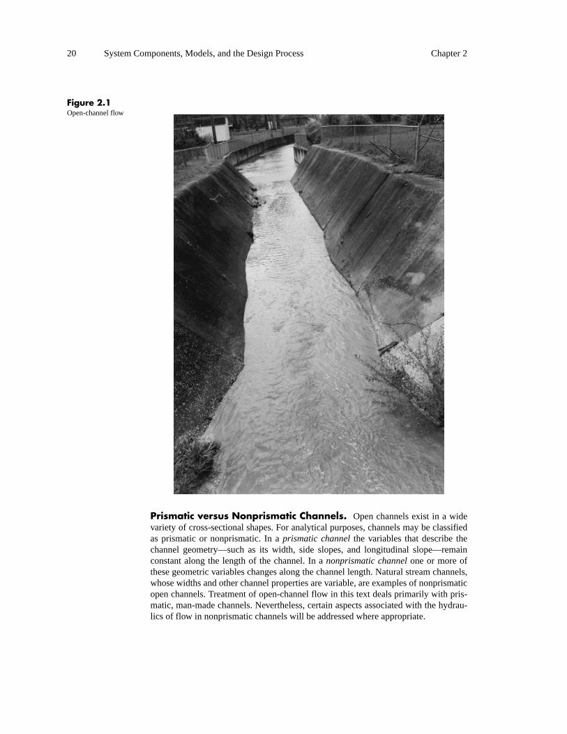
Open ChannelsOpen channels include natural stream channels, as well as natural swales (depres-sions) along which water runs following rainfall events. In the constructed or urban-ized environment, open channels include street gutters, drainage ditches, pipes, lined or unlined stormwater collection channels, and natural or modified stream channels. Figure 2.1 shows an example of flow in an open channel with a trapezoidal cross section.
Flow in a pipe is classified as open-channel flow if there is a water surface at atmo-spheric pressure (that is, a free water surface). For the purposes of this book, the term open-channel flow refers to any flow having a free water surface, regardless of whether it occurs in a closed conduit such as a culvert or storm sewer, aboveground channel, or other structure. Open-channel flow theory is presented in detail in Chapter7. However, when the text refers simply to an open channel in the context of physical characteristics or design approaches, as in Chapter 8, the term is meant to describe nonpipe conveyances only.
20 System Components, Models, and the Design Process Chapter 2
Figure 2.1Open-channel flow
Prismatic versus Nonprismatic Channels. Open channels exist in a wide variety of cross-sectional shapes. For analytical purposes, channels may be classified as prismatic or nonprismatic. In a prismatic channel the variables that describe the channel geometry—such as its width, side slopes, and longitudinal slope—remain constant along the length of the channel. In a nonprismatic channel one or more of these geometric variables changes along the channel length. Natural stream channels, whose widths and other channel properties are variable, are examples of nonprismatic open channels. Treatment of open-channel flow in this text deals primarily with pris-matic, man-made channels. Nevertheless, certain aspects associated with the hydrau-lics of flow in nonprismatic channels will be addressed where appropriate.

Section 2.2 Hydraulic Components 21
Materials. Open channels can also be classified on the basis of whether they are lined or unlined. The bottom and sides of an unlined channel consist of natural geo-logic materials such as earth, gravel, or rock. In a lined channel, the channel bottom and sides are covered with an erosion-resistant material such as concrete, asphalt, riprap, or vegetation.
As shown in Chapter 7, the channel’s lining material (or lack thereof) affects hydrau-lic performance characteristics such as flow depth and velocity. In turn, these same characteristics affect the erosive forces of the flow, thereby influencing the lining selection. The selection of the channel lining material is therefore a significant part of the hydraulic design process.
Model Representation. To model open-channel flow, the engineer must know the flow condition. With steady flow, flow characteristics such as discharge and veloc-ity are constant over time at a given point in the channel. When these characteristics do vary over time as a point, the condition is unsteady.
Steady flow can be further classified as either uniform flow or varied flow. Uniformflow is a condition in which the depth, velocity, cross-sectional area, and discharge are constant along the channel length. As a practical matter, this can happen only in a prismatic channel and only if the flow is steady. In uniform flow, the depth of flow is called normal depth.
Two models that can be used to describe uniform flow are the Manning equation and the Chézy equation. In their simplest forms, either of these equations may be used to calculate velocity or discharge as a function of channel slope, roughness and geome-try. In design, these models are used in a variety of ways. For example, for a given channel geometry, slope, roughness, and depth, the discharge may be calculated. Alternatively, if the channel geometry, material roughness, discharge and maximum allowable depth are specified, the required slope can be calculated. An example of a computer model used for uniform flow calculations is FlowMaster. Modeling of uni-form flow is covered in more detail in Section 7.3.
Varied flow is a condition in which the depth and velocity of flow change along the length of the channel. If the depth and velocity change only gradually, the flow is said to be gradually varied flow (GVF). If the depth and velocity change quickly over a short distance, as in a hydraulic jump, the flow is said to be a rapidly varied flow (RVF). Gradually varied flow occurs in all nonprismatic channels and in prismatic channels under the influence of a flow control other than normal depth. Because the curvatures of flow streamlines are small in a gradually varied flow, the pressure forces can be assumed to be hydrostatic. Constitutive relationships developed for uniform flow, such as the Manning equation, can be assumed to be valid for computing friction losses in gradually varied flow.
Because of the variable channel geometry and the presence of flow controls, the data required for gradually varied flow analysis are considerably more complex than for uniform flow analysis. The input includes channel cross-section geometry, reach lengths, channel roughness, and the water surface elevation at the control section. HEC-RAS is an example of a computer program frequently used in gradually varied flow profile calculations. For more information on gradually varied flow calculations, see Section 7.8.

22 System Components, Models, and the Design Process Chapter 2
Channel routing is a procedure by which the outflow at the downstream end of a channel reach is computed from inflow data and channel characteristics. It accounts for the effects of channel storage and travel time on discharge rates; thus, it is a type of unsteady flow modeling. Channel routing is applicable to both open channels and sewer systems when channel storage and/or travel time affect flow rate to a significant degree.
Channel routing may be accomplished by using either hydrologic or hydraulic routingmethods. Hydrologic routing is computationally simpler and less data-intensive, but usually is also less accurate. Hydrologic routing algorithms are based on the physical principle of conservation of mass and on an assumed storage relationship. Hydraulic methods are more physically based and employ conservation of mass and conserva-tion of momentum. Their use requires considerable data on channel geometry and roughness variables and on initial and boundary conditions of the flow itself. The Muskingum, Modified Puls, and Convex routing methods are examples of hydrologic routing models. (See Section 5.8 and Appendix C.) Hydraulic routing involves a solu-tion of the Saint-Venant equations, and may consist of kinematic, diffusion, or dynamic wave routing. Such methods are not well-suited to manual calculations but are coded into software packages such as HEC-RAS.
CulvertsA culvert is a relatively short underground water conveyance conduit. The primary purpose of a culvert, like that of a bridge, is to provide a means whereby the water in a stream or other open channel can pass through an obstruction such as a highway or railway embankment. Figure 2.2 shows a small culvert passing under a driveway.
Materials. Culverts come in a variety of shapes, sizes, and materials. As shown in Figure 2.3, cross-sectional shapes associated with culverts include circular, box, ellip-tical (horizontal or vertical orientation), and arched.
Common materials used for culvert design are reinforced precast or cast-in-place con-crete and corrugated steel. Other materials include corrugated aluminum, polyethyl-ene, and polyvinyl chloride (PVC). Discussions of these materials, including available shapes and sizes and sources of further information, are presented in Section 9.2.
The inlet and/or outlet ends of a culvert often receive special treatment. A culvert end may simply project from the embankment, or it may be mitered to conform to the embankment slope. It may also be fitted with a special flared end section or with a headwall and wingwalls. Section 9.3 discusses various types of end treatments and their hydraulic performance characteristics, as well as special inlet configurations that can be used when allowable headwater depths are limited.
Model Representation. A complete theoretical analysis of the hydraulics of a particular culvert installation is complex. Flow conditions vary from one culvert to the next, and they also vary over time. The barrel of the culvert may flow full or partially full, depending on upstream or downstream conditions, barrel characteristics, and inlet geometry. A commonly used method of analysis of culvert hydraulics was devel-

Section 2.2 Hydraulic Components 23
Figure 2.2A corrugated metal pipe culvert under a driveway
oped by the Federal Highway Administration and published as “Hydraulic Design Series No. 5: Hydraulic Design of Highway Culverts,” often referred to as HDS-5 (Norman, Houghtalen, and Johnston, 2001). Modeling software such as CulvertMas-ter follows the calculation methods set forth in HDS-5.
The following list describes the principal terms and concepts in culvert hydraulics More detailed information on culvert hydraulic analysis and HDS-5 methodologies is provided in Section 9.5 and Section 9.6.
• Headwater depth is the depth (relative to the culvert’s upstream invert eleva-tion) of flow just upstream of the culvert entrance. Any increase in energy required to push an increased discharge through a culvert translates into a greater headwater depth.
• Tailwater depth is the depth of water just downstream of the culvert outlet. The tailwater surface elevation may be dictated by downstream channel characteristics, by obstructions, or by a receiving-water elevation. An exit condition in which the tailwater depth is significantly less than the depth of flow in the culvert, and thus does not affect the upstream hydraulics, is called a free outfall.

24 System Components, Models, and the Design Process Chapter 2
Figure 2.3Common cross-sectional shapes for culverts
• The flow condition in a culvert can be characterized as either full (pressure) flow or partially full flow with a free water surface. Both free-surface and pressure flow can occur simultaneously at different locations within the same culvert. Uniform flow and gradually varied flow, as discussed earlier for open channels, apply to free-surface flow in culverts as well.
• The flow in a culvert may be controlled by conditions at either the inlet or the outlet of the culvert, so the type of control is classified as either inlet control or outlet control. In the case of inlet control, the hydraulic capacity of the culvert entrance limits the amount of water conveyed for a given headwa-ter depth; therefore, hydraulic characteristics downstream of the inlet control section do not affect the culvert capacity. In an outlet control condition, the culvert barrel capacity or downstream tailwater elevation limits the amount of flow that can be conveyed by the culvert for a particular headwater eleva-tion. The control section for outlet control is located at the barrel exit or fur-ther downstream.

Section 2.2 Hydraulic Components 25
• The flow velocity at the exit of a culvert is typically higher than that of the stream channel into which the culvert discharges. High outlet velocity can cause streambed scour and bank erosion in the vicinity of the culvert outlet. Minor problems occasionally can be avoided by increasing the barrel rough-ness, but structures such energy dissipators and/or outlet protection such as riprap are often necessary.
Storm Sewer SystemsA storm sewer system is a network of primarily subsurface structures for the collec-tion and conveyance of stormwater runoff. A typical storm sewer system consists of inlets through which stormwater enters from the land surface, pipes that convey this water, junction and manhole structures that serve as connection points for pipes and provide access to the subsurface system, and outlets or outfalls where stormwater is discharged to treatment facilities, to detention/retention structures, or into a larger conveyance such as an open channel.
Components and Materials. Storm sewer systems almost always include gutters, inlets, manholes, pipes, and outlet structures. Some systems may include stor-age and/or pumping facilities and other structures such as weirs. The following sub-sections briefly describe each of these components.
Although roadway gutters are not always considered a part of a stormwater manage-ment system, they are in fact an integral part of the system and are responsible for conveying runoff that collects in streets to inlets, where it enters the subsurface con-veyance system. A gutter may be formed by a curb along the edge of a street, or, for roads without curbs, it may consist of a shallow swale along the road edge. The vari-ous gutter types are presented in Section 10.1.
Figure 2.4 is a photo of a concrete curb-and-gutter section. The width of flow in the gutter is called the spread. Depending on the roadway classification and posted speed limits, allowable spread widths may extend beyond the roadway shoulder width and into the travel lane.
Curbs are typically composed of either precast, poured-in-place, extruded, or asphalt concrete. In some cases, a depressed section of gutter may be integrated with the con-crete curb, and the remainder of the gutter section is composed of the roadway pave-ment material.
A stormwater inlet is a structure for intercepting stormwater on the ground surface or in a roadway gutter and conveying it to the subsurface storm sewer piping system. Common inlet types are grate inlets (Figure 2.5), curb inlets (Figure 2.6), and combi-nation inlets (Figure 2.7).
For each of these three types, inlets can be further described as either continuous-grade inlets or sag inlets. A sag inlet is constructed in a low point where water drains to the inlet from all directions. With a continuous-grade inlet (also referred to as an inlet on grade), surface water may flow away from the inlet opening in one or more directions.

26 System Components, Models, and the Design Process Chapter 2
Figure 2.4Concrete curb and gutter
Below the ground surface, inlets consist of box-like structures that support the inlet opening (for example, the grate) and connect to the system piping. The inlet box is typically constructed of precast reinforced concrete. Other materials include poured-in-place concrete, corrugated metal, brick, and block. A catch basin is a special type of inlet box designed to trap sediment and debris.
Although not considered inlets per se, runoff from streams and channels can enter storm sewer systems through culvert-type entrances such as headwalls. Additional specialized inlet types are discussed in Section 10.2.

Section 2.2 Hydraulic Components 27
Figure 2.5A grate inlet in a triangular gutter section
Figure 2.6A large curb inlet

28 System Components, Models, and the Design Process Chapter 2
Figure 2.7A combination inlet
Manholes, sometimes called access holes, are usually installed in sewers at locations where pipes join, change direction, or change size. They provide access to the system for inspection and maintenance. Manholes for relatively small-diameter sewers generally consist of a concrete or masonry base, which ideally has been formed to aid in reducing the energy loss associated with water traveling from the inlet pipe(s) to the outlet pipe. Figure 2.8 shows a precast concrete manhole structure prior to installation. Junction structures, like manholes, are used where two or more pipes join one another. However, junction structures tend to be associated with larger or more complex installations and are often custom-made.
For storm sewer pipes, circular pipe is the most typical cross-sectional shape, but, as with culverts, a variety of cross-sectional shapes are available (see Figure 2.3). Ellipti-cal and arch-shaped cross sections may be used for instances in which vertical or hor-izontal clearances are limited. Rectangular concrete box sections are also available. Concrete pipe (shown in Figure 2.9) is available in both nonreinforced and reinforced varieties and in a range of wall thicknesses and strength classes and is probably the most commonly used pipe material for storm sewer construction.

Section 2.2 Hydraulic Components 29
Figure 2.8A precast manhole structure
Corrugated metal pipe (or CMP) is also used frequently in storm sewers (see Figure 2.10). Like concrete pipe, CMP is manufactured in a number of cross-sectional shapes and sizes and in strict accordance with standard specifications. Corrugated steel prod-ucts include circular and arch pipes, structural plate pipe-arches, and structural plate arches, with the last requiring bolted assembly in the field. Various coatings and steel thicknesses are available.
Although concrete and corrugated steel pipes are by far the most common in storm sewer and culvert applications, other materials, such as corrugated aluminum, poly-ethylene, and polyvinyl chloride (PVC), are used as well. PVC pipes are shown in Figure 2.11.

30 System Components, Models, and the Design Process Chapter 2
Figure 2.9Concrete pipes
Figure 2.10Corrugated metal pipe (CMP)
Storm sewers may outfall to the ground surface, into a natural or man-made body of water, or into detention or treatment facilities. Exit velocities at storm sewer outfalls are often large enough to cause erosion problems and potential undermining of the outfall pipe. Outlet structures dissipate the excess energy of the flow and prevent undermining. An outlet structure may be as simple as a concrete headwall with a riprap and filter blanket downstream of the outfall point, or it may consist of a more complex energy dissipator or stilling basin.

Section 2.2 Hydraulic Components 31
Figure 2.11PVC pipes
In most cases, stormwater management systems are designed as gravity systems. Pumping of stormwater is generally undesirable because it significantly increases the cost of stormwater conveyance but cannot be avoided in some instances. For storm-water pumping purposes, the most common types of pumps are axial-flow pumps, radial-flow pumps, and mixed-flow pumps. Both wet-well and dry-well installations are found in stormwater pumping applications. Chapter 13 provides information on the design of stormwater pumping systems.
Model Representation. Many components are involved in modeling a storm sewer system, and various levels of model complexity exist for their analysis. The hydraulic design or analysis of a storm sewer can typically be broken down into two major parts: surface hydraulics (that is, gutter flow and inlet capacity) and subsurface hydraulics (pipe capacity and energy losses). Other possible components are pump stations and storage facilities.
Levels of analysis that may be performed on storm sewers include:
• Use of a steady-state model that ensures the system can handle peak flows.
• Use of an extended-period simulation (EPS) analysis that applies hydrologic routing and that may also simulate inter-storm time periods.
• Use of a dynamic model that solves the full Saint-Venant equations.

32 System Components, Models, and the Design Process Chapter 2
A steady-state analysis is typically sufficient for design applications that do not involve system flooding or storage facilities and for which the peak flows from vari-ous subbasins arrive at the outlet at roughly the same time. This type of analysis is the primary focus of this text. The paragraphs that follow describe basic steady-state model requirements for surface systems, subsurface systems, and pumping facilities.
The surface portion of a storm sewer system consists of gutters and other open chan-nels, and inlet structures. Gutter hydraulics are typically modeled as uniform flow in an open channel. Specialized forms of the Manning equation have been developed to facilitate this calculation and are given in Section 10.1. The data required are the dis-charge, the geometry of the street (longitudinal and transverse slopes) the height of the curb, and the roughness of the pavement.
Inlets in sag locations operate as weirs for shallow flows and as orifices for greater flow depths. The forms of the weir and orifice equations used for computing the capacities of curb-opening and grate inlets are presented in Section 10.2 of this text. For grated inlets, information on the grate perimeter and open area is required. For curb inlet calculations, the dimensions of the curb opening and the local depression are necessary.
Calculations for inlets on grade are somewhat more complex, as all of the flow that comes toward the inlet may not be intercepted. A portion of the flow in the gutter, termed bypass flow, may flow over or around the inlet and continue downgradient. The calculation of intercepted flow and bypass flow is performed using empirical methods that take into account the velocity of the flow in the gutter relative to the inlet length, the amount of inlet depression, and the inlet’s splash-over velocity (for grate inlets, the critical velocity at which a portion of the flow begins to splash over the inlet). Section 10.2 provides the equations describing the capacity of inlets on grade.
Inlet bypass flows form a surface network for stormwater runoff similar to the way sewer piping forms a subsurface network. Manual calculations for inlet capture and bypass can be quite tedious if a project has a large number of inlets on grade. Some computer programs used for computing inlet and gutter hydraulic characteristics are simple equation-solvers that look at each structure individually. An example of this type of program is FlowMaster, which is useful for performing quick calculations on small systems.
Other computer programs allow the user to develop a network of on-grade inlets, inlets in sag, and gutters. These programs analyze the surface system using the same methodologies as the simpler programs, but alterations in the loading of gutters and inlets due to upstream bypass flows are automatically taken into account. Typically, this type of program will also perform the subsurface hydraulic calculations. Many software packages are available for this application, but one popular package is StormCAD (Haestad, 2003b).
Flow in the subsurface system is modeled as one of two flow conditions (see Table 2.1). When a pipe is not full and the water surface is open to the atmosphere, the flow is modeled as open-channel flow. A friction loss equation such as the Manning or Chézy equation may be used to determine flow depths and velocities. When a pipe is flowing full (that is, it is surcharged), closed conduit pressure flow calculation

Section 2.2 Hydraulic Components 33
methods are used. The data requirements for these calculations are discharge, pipe size, roughness, length, and slope.
In a storm sewer network, the minor energy losses that occur at inlets, at locations where pipe size or alignment changes, and at outlets can be significant. Data require-ments for computing these losses include the geometry of the structure and the entrance and exit velocities. Several methods for computing minor losses are available (see Sections 6.3 and 11.4), and computer models such as StormCAD can compute these losses as part of a network analysis.
The operating characteristics of a pump, when installed in a piping system, can be ascertained from graphs of pump and system curves. These characteristics include the energy head produced by the pump, the corresponding pump discharge, the brake horsepower requirements for the pump motor(s), and the net positive section head required to avoid cavitation damage to the impeller and other internal parts. Methods for determining these operating characteristics, for both single- and multiple-pump installations, are presented in Section 13.3.
Stormwater Detention and RetentionA common objective in stormwater management is to maintain the peak runoff rate from a developing area to a value no greater than the predevelopment rate. This prac-tice will reduce local flooding, soil erosion, sedimentation, and pollution. Local gov-erning bodies typically establish specific design criteria for peak flow attenuation. Detention basins reduce the magnitude of peak flows by temporarily storing the run-off and releasing it over an extended period of time. Additionally, ponds often func-tion as sedimentation basins, reducing the concentration of suspended materials in the discharge.
Detention Basin Types and Components. Wet ponds are designed to maintain a minimum water depth between storms. Dry ponds are designed to com-pletely discharge stored runoff between storms. The configuration of a detention pond is generally dictated by site conditions. A dry detention pond is shown in Figure 2.12.
The most common detention facility designs are earthen basins or ponds located downstream of the collection area and upstream of the discharge point. The detention pond’s outlet structure controls the rate at which runoff may discharge from the facil-ity. Common outlet structure devices include weirs, orifices, culverts, inlet boxes, and standpipes. Most ponds are also equipped with an emergency overflow spillway to handle flows if the primary outlet becomes clogged, or if a storm has a magnitude greater than the pond’s design event.
Model Representation. Detention ponds are modeled using the routing proce-dures described in Section 12.7. The basic data requirements are an inflow hydrograph, the depth to volume relationship of the pond, and the hydraulic charac-teristics of the outlet structure.

34 System Components, Models, and the Design Process Chapter 2
Figure 2.12Dry detention pond
Capabilities of computer programs for stormwater detention modeling vary widely. The most basic programs allow for hydrograph input into a single pond with a simple outlet such as an orifice or weir, and the pond is routed using a technique such as storage-indication routing or numerical integration. More powerful models, such as PondPack (Haestad Methods, 2003a), can analyze networked watersheds and multiple ponds, interconnected ponds, and complex outlet structures. Fully dynamic stormwa-ter modeling programs allow storage facilities to be modeled together with other ele-ments of the stormwater conveyance system.
Summary of Hydraulic Models for Various Components of Stormwater Management SystemsA number of computer modeling software programs are available for virtually all of the methods presented in this text, and some examples of these programs have been mentioned in this chapter. However, because of the wide variety of structure types and available calculation techniques used in the field of stormwater management, there is great variation and specialization among the available programs. The primary thrust of this text as it relates to computer modeling is to aid the reader in understanding the methodologies underlying the programs. Such understanding is necessary if the engi-neer is to apply the computer programs correctly and confidently.
Table 2.1 lists the numerical models frequently used to describe the behavior of vari-ous components of stormwater conveyance systems, the input data required by these models, and references to the sections of this book where each model is discussed. It should be noted that most software programs can implement a collection of models from this list. For instance, modeling software for storm sewer systems would likely include solvers for uniform, gradually varied, and pressure flow; gutter flow; inlet performance; and minor losses in manholes.

Section 2.2 Hydraulic Components 35
Note: This table is repeated in Appendix D. That version lists the software program on the accompanying CD-ROM that can be used with each type of model component.
Table 2.1 References for common stormwater conveyance system component models
Component Modeling Methods Typical Input data Section of Text
Channel with uni-form flow
Manning equation, Chézy equation, or Darcy-Weisbach equation
Channel roughnessChannel geometryChannel slopeDischarge or velocity
7.3
Channel with gradu-ally varied flow
Direct-step method orstandard-step method
Geometry of each cross sectionStarting water surface elevation
7.8
Channel with flow routing
Muskingum Historical flood data or routing coefficients
Inflow hydrograph
5.8
Modified Puls Geometry of outletInflow hydrograph
5.8
Saint-Venant equations Channel geometryInflow hydrograph
Appendix C
Culvert with inletcontrol
HDS-5 methodology Inlet geometryDischarge
9.5
Culvert with outlet control
HDS-5 methodology Pipe geometryPipe materialInlet geometryDischarge Tailwater elevation
9.5
Roadway overtop-ping
HDS-5 methodology Roadway profile coordinatesType of roadRoadway widthDischarge
9.6
Gutter flow Manning equation or Chézy equation
Roadway slopesCurb heightPavement roughnessDischarge
10.1
Storm sewer pipes with open channel flow
Manning equation or Chézy equation; Saint-Venantequations
Pipe roughnessPipe geometryPipe slopeDischarge or velocity
7.3; 7.4; 7.5; 7.811.5; Appendix C
Storm sewer pipes with pressure flow
Darcy-Weisbach,Manning, Hazen-Williams, or Chézy equation; Saint-Venant equations
Pipe roughnessPipe geometryPipe slopeDischarge or velocityTailwater conditions
6.2; 6.3; 11.5;Appendix C
Inlets Weir and orifice equations Discharge Inlet type and geometry
10.2
Manholes Minor loss equations Entrance and exit velocitiesStructure geometry
6.3; 11.4
Diversions/over-flows
Weir and/or orifice equations GeometryWater surface elevations
7.6; 7.7
Pumps Energy equationSystem equilibrium
Pump head-discharge curvesSystem curve(s)
13.3; 13.7
System outlets Weir equationsOrifice equationsMinor loss equationsEnergy dissipation model
Boundary conditions such as tail-water data or downstream chan-nel characteristics
Geometric characteristics of outlet
6.3; 9.5; 11.7
Detention ponds Hydrologic routing andHydraulic routing
Inflow hydrographDepth vs. volume for pondGeometry of outlet or stage-
discharge curve
12.6; 12.7

36 System Components, Models, and the Design Process Chapter 2
2.3 THE DESIGN PROCESSThe urban stormwater infrastructure can be viewed as consisting of a minor system and a major system. The minor system is designed to handle frequent events with return periods typically on the order of 2 to 10 years. The minor system consists of, for instance, roadway gutters, inlets, and pipes.
The major system consists of the pathways taken by flows in excess of the capacity of the minor system. It can be thought of as inundated roadways, swales and depres-sions, and natural and man-made open channels. A major system always exists, even when a minor system does not. Unfortunately, major systems are often neglected and do not receive the attention that they warrant, especially in light of the high probabil-ity of operational failure of the minor system.
The overall process of designing a storm drainage system can be broken down into a number of phases. These phases are
1. Master planning
2. Concept and preliminary design development
3. Detailed design
4. Preparation of construction drawings, specifications, and contract documents
Each of these phases is described more fully in the sections that follow.
Master PlanningMaster planning, often conducted for an entire urban area by a drainage-system authority or review agency, provides a holistic view of the urban drainage system and how its various components interact. The need for master planning is particularly acute where an urbanized area spans a number of different political jurisdictions, each having its own objectives and design criteria. In such instances, master planning can help ensure that systems that cross jurisdictional boundaries are consistent with one another. Even if only one political jurisdiction is involved, master planning provides useful guidance for constructing new drainage systems that are consistent not only with one another, but also with existing facilities.
The issues that should be addressed by a master plan are, at a minimum, delineations of major urban drainageways (whose floodplains might be mapped for flood insur-ance purposes) and approximate limits and locations of storm sewers in the contribut-ing drainage basin(s). The master plan should make a clear distinction between the minor and major drainage systems, and it should also take whatever steps are politi-cally and legally possible to ensure that the major system is functional and provides a reasonable degree of protection from severe storm events.
Technically, a master plan should contain enough detail to be an effective guide to the ultimate construction and/or rehabilitation of storm drainage facilities in the area cov-ered by the plan. Hydrologic analyses should have sufficient detail to provide reason-able estimates of required system conveyance capacities and should address estimates of expected future flows in developing drainage basins. Zoning master plans, where
Section 2.3 The Design Process 37
available, are invaluable for providing estimates of ultimate land uses in a drainage basin.
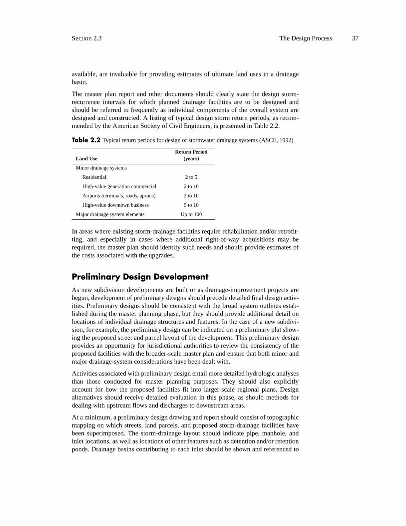
The master plan report and other documents should clearly state the design storm-recurrence intervals for which planned drainage facilities are to be designed and should be referred to frequently as individual components of the overall system are designed and constructed. A listing of typical design storm return periods, as recom-mended by the American Society of Civil Engineers, is presented in Table 2.2.
In areas where existing storm-drainage facilities require rehabilitation and/or retrofit-ting, and especially in cases where additional right-of-way acquisitions may be required, the master plan should identify such needs and should provide estimates of the costs associated with the upgrades.
Preliminary Design DevelopmentAs new subdivision developments are built or as drainage-improvement projects are begun, development of preliminary designs should precede detailed final design activ-ities. Preliminary designs should be consistent with the broad system outlines estab-lished during the master planning phase, but they should provide additional detail on locations of individual drainage structures and features. In the case of a new subdivi-sion, for example, the preliminary design can be indicated on a preliminary plat show-ing the proposed street and parcel layout of the development. This preliminary design provides an opportunity for jurisdictional authorities to review the consistency of the proposed facilities with the broader-scale master plan and ensure that both minor and major drainage-system considerations have been dealt with.
Activities associated with preliminary design entail more detailed hydrologic analyses than those conducted for master planning purposes. They should also explicitly account for how the proposed facilities fit into larger-scale regional plans. Design alternatives should receive detailed evaluation in this phase, as should methods for dealing with upstream flows and discharges to downstream areas.
At a minimum, a preliminary design drawing and report should consist of topographic mapping on which streets, land parcels, and proposed storm-drainage facilities have been superimposed. The storm-drainage layout should indicate pipe, manhole, and inlet locations, as well as locations of other features such as detention and/or retention ponds. Drainage basins contributing to each inlet should be shown and referenced to
Table 2.2 Typical return periods for design of stormwater drainage systems (ASCE, 1992)
Land UseReturn Period
(years)
Minor drainage systems
Residential 2 to 5
High-value generation commercial 2 to 10
Airports (terminals, roads, aprons) 2 to 10
High-value downtown business 5 to 10
Major drainage system elements Up to 100

38 System Components, Models, and the Design Process Chapter 2
accompanying hydrologic estimates of design flows in the report. Finally, the prelim-inary design report should explicitly address the major drainage system, including the general pathways and directions of major system flow on the design drawing.
Detailed Design Following the approval of the preliminary design by the appropriate jurisdictional authorities, the engineer can proceed with the detailed design. As the name implies, this phase involves detailed engineering analyses that will serve as the basis for the design described by the construction plans and specifications.
Detailed hydrologic and hydraulic analyses must be performed at this stage to finalize design discharges and determine the dimensions of hydraulic structures, such as pipes, inlets, ponds, and energy dissipators. Structural analyses are necessary to deter-mine required pipe strength classes or wall thicknesses and may also be required for other project-specific hydraulic structures. Geotechnical analyses are necessary to locate shallow bedrock that could affect construction costs; to determine groundwater elevations that could affect trenching, buoyancy forces on submerged pipes and struc-tures, and pipe infiltration; and to determine pipe-bedding requirements.
It is essential that complete and well-organized files be maintained to document each activity and decision in the detailed design phase. Should unforeseen circumstances occur during construction, or should litigation arise after construction of the system has been completed, these files will provide a record of the adequacy of the design and its adherence to accepted engineering practices.
Construction Drawings, Specifications, and Contract DocumentsConstruction drawings should be prepared as the final design is completed and should go hand in hand with that activity. Construction plans consist of plan and profile sheets showing horizontal and vertical alignments of new and existing facilities, including all dimensions required for a survey crew to lay out the system in the field. Plan views should indicate the locations, elevations, and dimensions of all proposed pipes, inlets, manholes, and other system features, and should show at least approxi-mate locations of existing utilities that could pose potential conflicts. Existing land-surface features, such as curbs, walks, and other structures requiring demolition and subsequent replacement, should also be shown.
Profile views should include required pipe slopes and invert elevations, existing and proposed ground-surface elevations, approximate limits of bedrock, and approximate elevations of underground utilities. If the construction contractor is to perform utility relocations, then construction requirements for the relocations must also be included in the plans. It is sometimes desirable to show energy and hydraulic grade-line pro-files on construction plans; they are certainly not needed for construction, but may be required for regulatory submittals.
In addition to plan and profile drawings, construction plans should clearly identify required materials and material classes and should provide construction details, such

Section 2.4 Integration of Stormwater Conveyance Modeling with CAD Software and GIS 39
as reinforcing steel layouts, for any special structures. Some construction details may already be available in sets of standard plans published by, for example, transportation departments. As a courtesy to project bidders, construction plans may also include one or more sheets containing tabulations of estimated material quantities.
Technical specifications are the heart of any set of construction documents, spelling out in detail the required construction methods and material types, classes, and testing requirements. It is common to reference standard construction specifications pub-lished by jurisdictional agencies, but care should be taken to avoid conflicting require-ments in the plans and technical specifications. There may be conflicts between the engineer’s specifications and standard specifications, between standard specifications and construction plans, or both. There is no such thing as a “standard project.” Stan-dardized technical specifications must be viewed with a wary eye.
The contract documents for a construction project consist of the plans, technical spec-ifications, and other “boiler-plate” provisions. These additional provisions generally consist of bidding documents, bonds, official notices to proceed and notices of project acceptance, and general and special conditions of the contract. The general conditions typically specify such things as owner-engineer-contractor responsibilities and job-site requirements relating to issues such as materials storage, sanitation, site cleanup, and conformance with applicable laws and regulations. The general conditions are typically a standard document used for all construction contracts within a jurisdic-tional area. The “Standard General Conditions of the Construction Contract” docu-ment from the Engineers Joint Contract Documents Committee (EJCDC, 2002) is a widely used set of general conditions in the United States Special conditions, which are project-specific and assembled by the engineer, identify requirements other than those specified in the general conditions, and can also be used to modify provisions of standardized technical specifications.
2.4 INTEGRATION OF STORMWATER CONVEYANCE MODELING WITH CAD SOFTWARE AND GIS
The integration of conveyance modeling with computer-aided design (CAD) pro-grams and geographic information systems (GIS) has a number of benefits. Hydraulic and hydrologic design and analysis software often includes both CAD and GIS-type features. In some cases, analysis applications can run directly within an organization’s preferred CAD or GIS platform. This section describes some of the benefits of lever-aging CAD and GIS capabilities in hydraulic design and analysis.
CAD IntegrationCAD software can be useful in both the initial and final stages of a hydraulic design project. A CAD drawing typically provides the base plan for the layout of stormwater management facilities such as sewer networks, channels, and detention ponds. After the facilities have been designed, this plan is updated to reflect proposed structures for inclusion in the construction documents.

40 System Components, Models, and the Design Process Chapter 2
Software applications interact with CAD systems in a variety of ways. A graphics-based application such as StormCAD may be capable of displaying a background CAD file for use in system layout, or the hydraulic analysis application may run directly inside of a CAD program such as AutoCAD (see Figure 2.13) or Microsta-tion. CAD features can be used to fine-tune system layout and supply data on the topography and horizontal and vertical structure coordinates. Many CAD programs used by civil engineers are equipped with special tools for assisting engineers in cre-ating roadway grading plans and drawing sewer profiles.
Figure 2.13Storm sewer plan and profile created using hydraulic design software running inside of AutoCAD
Engineers can choose from various approaches when integrating hydraulic design with a CAD application. Several possible options, ordered from least to greatest degree of integration, are as follows:
• No automated data exchange occurs between the CAD program and the hydraulic modeling software. The engineer manually enters schematic data on the hydraulic system into the analysis software and designs the system. The system characteristics resulting from the design are then manually input into the CAD drawing for inclusion in construction documents.
• A CAD drawing containing the background information necessary to lay out the stormwater facilities is used as a background map in the hydraulic design software. After the system’s layout is completed and its elements designed, the layout is imported into the CAD drawing. Other element characteristics are added to the drawing manually.
• The initial hydraulic system layout is created in the CAD drawing and imported into the analysis program. Depending on the features of the CAD

Section 2.4 Integration of Stormwater Conveyance Modeling with CAD Software and GIS 41
software, the data imported may include, in addition to the horizontal layout (that is, coordinate and/or connectivity data), elevation information, structure types, preliminary structure sizes, and other characteristics. Once the design is final, system data can be transferred back into the CAD application through automated import/export methods.
• An analysis application that runs directly within the CAD platform is used. In the design process, hydraulic structures are inserted directly into the draw-ing file, and data are readily available from both the CAD program and hydraulic design tool. This technique is the most efficient of the various inte-gration approaches.
Typically, increased integration of CAD and hydraulic design and analysis applica-tions translates to less data duplication, decreased opportunities for the introduction of errors and omissions, and increased time savings.
GIS IntegrationA geographic information system (GIS) is a powerful configuration of computer hard-ware and software used for compiling, storing, managing, manipulating, analyzing, and mapping (displaying) spatially referenced information. It combines the function-alities of a computer graphics program, an electronic map, and a database.
Like CAD, a GIS can be used in many stages of stormwater conveyance modeling. Although CAD programs provide an excellent format for developing technical draw-ings, they generally do not provide a means of storing data associated with those drawings. For example, a CAD drawing may show a stormwater pipe network for a neighborhood. However, if the engineer is to model the network using information from the drawing, the drawing must contain detailed annotations for each structure describing characteristics such as pipe material, size, and inlet and outlet elevations. A GIS, by comparison, can store model information in an internal database associated with each GIS data layer. The database functions of a GIS also allow data to be stored and maintained externally and accessed when needed through a dynamic database link.
GIS software typically has tools for drawing (digitizing), map display, data storage, and data analysis. The digitizing tools allow for conversion of hard-copy drawings to an electronic format and are almost identical to those of CAD programs. Map display tools allow users to change the appearance of different types of features (points, lines, polygons, and text) according to values in the database. [For instance, within a single layer, all 6-in. (150-mm) pipes may be shown in red, with concrete pipes displayed as solid lines and corrugated steel pipes displayed as dashed lines.] The data storage tools are similar to those of many database programs, with data lookup, query, and sort functions.
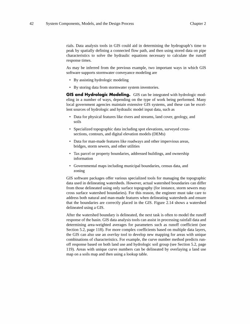
The data analysis tools of GIS make it well-suited to supporting stormwater convey-ance modeling. These tools allow users to consider both spatial and data relationships to develop new data or to provide model inputs. For example, one may be trying to evaluate the runoff response of a watershed by looking at information about a storm sewer trunk line, which may be made up of multiple pipes of different sizes and mate-
42 System Components, Models, and the Design Process Chapter 2
rials. Data analysis tools in GIS could aid in determining the hydrograph’s time to peak by spatially defining a connected flow path, and then using stored data on pipe characteristics to solve the hydraulic equations necessary to calculate the runoff response times.
As may be inferred from the previous example, two important ways in which GIS software supports stormwater conveyance modeling are
• By assisting hydrologic modeling
• By storing data from stormwater system inventories.
GIS and Hydrologic Modeling. GIS can be integrated with hydrologic mod-eling in a number of ways, depending on the type of work being performed. Many local government agencies maintain extensive GIS systems, and these can be excel-lent sources of hydrologic and hydraulic model input data, such as
• Data for physical features like rivers and streams, land cover, geology, and soils
• Specialized topographic data including spot elevations, surveyed cross-sections, contours, and digital elevation models (DEMs)
• Data for man-made features like roadways and other impervious areas, bridges, storm sewers, and other utilities
• Tax parcel or property boundaries, addressed buildings, and ownership information
• Governmental maps including municipal boundaries, census data, and zoning
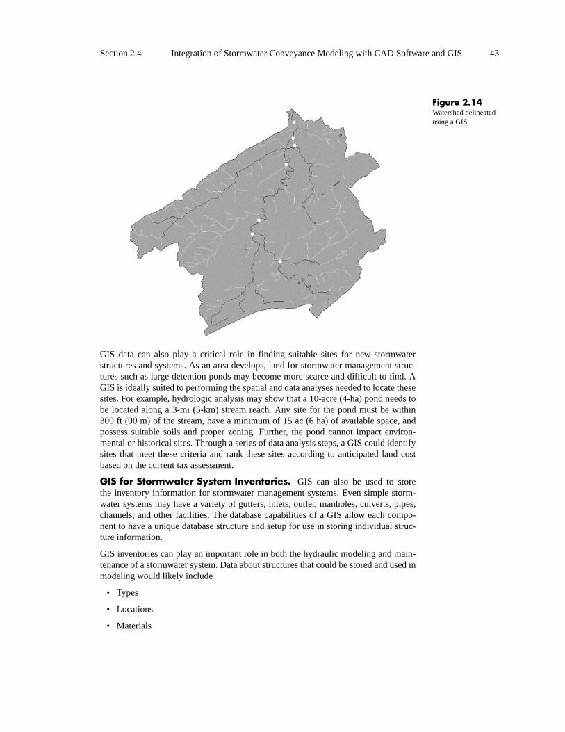
GIS software packages offer various specialized tools for managing the topographic data used in delineating watersheds. However, actual watershed boundaries can differ from those delineated using only surface topography (for instance, storm sewers may cross surface watershed boundaries). For this reason, the engineer must take care to address both natural and man-made features when delineating watersheds and ensure that the boundaries are correctly placed in the GIS. Figure 2.14 shows a watershed delineated using a GIS.
After the watershed boundary is delineated, the next task is often to model the runoff response of the basin. GIS data analysis tools can assist in processing rainfall data and determining area-weighted averages for parameters such as runoff coefficient (see Section 5.2, page 118). For more complex coefficients based on multiple data layers, the GIS can also use an overlay tool to develop new mapping for areas with unique combinations of characteristics. For example, the curve number method predicts run-off response based on both land use and hydrologic soil group (see Section 5.2, page119). Areas with unique curve numbers can be delineated by overlaying a land use map on a soils map and then using a lookup table.
Section 2.4 Integration of Stormwater Conveyance Modeling with CAD Software and GIS 43
Figure 2.14Watershed delineated using a GIS
GIS data can also play a critical role in finding suitable sites for new stormwater structures and systems. As an area develops, land for stormwater management struc-tures such as large detention ponds may become more scarce and difficult to find. A GIS is ideally suited to performing the spatial and data analyses needed to locate these sites. For example, hydrologic analysis may show that a 10-acre (4-ha) pond needs to be located along a 3-mi (5-km) stream reach. Any site for the pond must be within 300 ft (90 m) of the stream, have a minimum of 15 ac (6 ha) of available space, and possess suitable soils and proper zoning. Further, the pond cannot impact environ-mental or historical sites. Through a series of data analysis steps, a GIS could identify sites that meet these criteria and rank these sites according to anticipated land cost based on the current tax assessment.
GIS for Stormwater System Inventories. GIS can also be used to store the inventory information for stormwater management systems. Even simple storm-water systems may have a variety of gutters, inlets, outlet, manholes, culverts, pipes, channels, and other facilities. The database capabilities of a GIS allow each compo-nent to have a unique database structure and setup for use in storing individual struc-ture information.
GIS inventories can play an important role in both the hydraulic modeling and main-tenance of a stormwater system. Data about structures that could be stored and used in modeling would likely include
• Types
• Locations
• Materials

44 System Components, Models, and the Design Process Chapter 2
Data useful in maintenance efforts may include
• Inspection reports
• Maintenance logs
• Public works complaint records
The database linking capability of the GIS is important, because many of the mainte-nance records may be stored in databases of several different local government departments.
GIS integration with stormwater modeling, like CAD integration, can range from no automated data exchange to complete integration within a GIS platform. However, the data analysis and database capabilities that can be performed using a GIS are more complex and, in many cases, can substantially reduce the number of data-entry steps. The data exchange between a model and a GIS is two-way: a GIS can provide existing information to a model, and data from a model of a new system can be imported into a GIS to update a stormwater system inventory. Some hydraulic analysis applications (for example, StormCAD) provide a means of automatically synchronizing data with a GIS. Figure 2.15 shows storm sewer system data stored in a GIS.
Figure 2.15Information on a storm sewer system can be stored in a GIS
2.5 Sources of Model DataThe typical stormwater conveyance project, whether it is a new design or a study of an existing system, uses data from a variety of sources. At the beginning of a project, the engineer should consider what the data requirements for the project will be, including data types, quality, and quantity. Once these requirements have been defined, it is usu-ally a straightforward effort to identify the data sources. When multiple sources are

Section 2.5 Sources of Model Data 45
available for a specific data type, the choice of which source to use is based on bal-ancing cost with data quality.
Proposed SystemsFor proposed systems, most of the model input is developed by the engineer as part of the design process and will be subject to constraints dictated by project goals, site conditions, and local design standards. Common sources of data utilized in the design of new systems are described in the paragraphs that follow.
Surveys. For proposed systems, survey data are used as the base upon which the proposed layout and grading plans, and therefore stormwater conveyance designs, are developed. A survey also provides information on existing watercourses, drainage systems, utilities, and various obstacles in the project area, and aids the engineer in avoiding conflicts with these features. Of particular interest to stormwater conveyance designers is survey information on the site’s outfall(s). The outfall location provides the engineer with a controlling elevation that the proposed system must tie into. For cases in which a proposed sewer system will tie directly to an existing sewer system, information on existing structure characteristics is required.
Layout and Grading Plans for the Proposed Site. The design of the stormwater conveyance system for a project is typically performed concurrently with or following the development of the layout and grading plans. These plans serve as the primary source of information for development of the preliminary drainage sys-tem layout. The proposed grading reveals the site’s major catchment areas and pro-vides the ground elevations required by the model.
Hydrologic Data Sources. Hydrologic data are available from a variety of sources. For most designs, local rainfall data and design storm information can be obtained from the local review agency. Transportation departments are another possi-ble source of hydrologic data, as are governmental organizations such as the National Weather Service and Natural Resource Conservation Service in the United States. Often, data are readily available through an organization’s web site. Further informa-tion on hydrologic data sources is presented in Chapters 4 and 5.
Local Design Standards. Local design standards provide a number of con-straints in drainage design and may originate from more than one source (for instance, in addition to city or county requirements, state environmental regulations and trans-portation department standards may also be applicable to a single design project). Requirements frequently include
• Minimum pipe or culvert size
• Acceptable pipe or culvert materials
• Approved inlet types
• Design storm event return periods
• Maximum gutter spread and depth
• Minimum inlet capture efficiency

46 System Components, Models, and the Design Process Chapter 2
• Maximum distance between manholes
• Minimum freeboard requirement
• Stormwater detention requirements
• Accepted analysis techniques and applicable procedures and coefficients
• Submittal requirements for permitting
When beginning a drainage design in an unfamiliar jurisdiction, it is best to contact the local reviewing agency or agencies early in the design process to discuss theapplicable requirements and obtain a copy of the local stormwater regulations/design guidelines, if available. This preparation can save considerable time later in the process.
Existing SystemsThe sources of information used in evaluating the performance of an existing storm-water facility such as a sewer system, detention basin, or roadway culvert are often the same as those used in new designs, but the approach to the project will differ somewhat. On the surface, the analysis of an existing system may appear to be an eas-ier task than designing new facilities: the geometry of the system is known, and topo-graphic information can be taken directly from a survey rather than from a proposed design. However, the analysis of an existing system often presents other challenges, as such studies almost always stem from problems such as undersized piping and flood-ing in the area. The modeler is faced with the forensic problem of trying to re-create what happens in a real system, as opposed to simply sizing system components for a synthetic design event.
Surveys. Survey data are relied on much more extensively in the analysis of an existing system than in the design of a new system. For instance, a number of storm sewer manholes and inlet structures must often be field-located and their covers removed to determine pipe sizes, orientations, and invert elevations. Ponds and depressions that serve as detention basins must be carefully surveyed, and these areas are often wet or overgrown, making access difficult. Detention outlet structures must also be surveyed carefully to model the basin accurately, including planned or unplanned overflow spillways. If a culvert roadway crossing is being examined, the culvert entrance type must be noted and the roadway profile surveyed for overtopping analysis. A detailed topographic survey may also be needed to determine drainage subbasin areas.
Site Reconnaissance. When conducting a study of an existing drainage system, it is advisable for the engineer to make at least one site visit. A visit to the site pro-vides an opportunity to
• Resolve ambiguities in the survey
• Examine and delineate contributing drainage areas that may lie outside of the survey area
• Observe the condition of the existing infrastructure

Section 2.5 Sources of Model Data 47
• Look for project-related problems such as soil erosion, debris in drainage-ways, and water quality issues
• Observe watershed and drainageway characteristics to determine model parameters such as channel roughnesses, runoff coefficients, and culvert entrance types
• Photograph the site to assist other engineers involved in the project, provide answers to questions that may arise after the site visit, and provide a record of site conditions
Original Plans and Design Calculations. A great deal of information use-ful in the study of an existing system can be obtained from original construction doc-uments and design calculations. The compliance of the constructed system with the original plans must still be verified through a survey, but these plans do help the engi-neer to understand the original intent of the designer. They are an excellent starting point for the engineer in deciding what information the surveyor should gather. The engineer can also use the plans to identify problems in the system resulting from dif-ferences in the intent of the designer and the constructed system—problems that may be alleviated by altering the site to bring it into closer agreement with the original plan—or to identify deficiencies in the original design.
The original hydraulic and hydrologic design calculations can also be of help to the engineer. The model input data and calculations can be verified for accuracy, which can aid the discovery of why the system is not providing the anticipated level of pro-tection. For instance, a contributing drainage area upstream of the project’s convey-ance system may have been developed since the project’s construction and be contributing more runoff than it was previously.
As-Built Surveys/Drawings. When available, as-built drawings can be an excellent source of information when conducting a study of an existing system. These drawings may be obtained from the property owner, the engineer who did the original design, the surveyor who performed the as-built survey, or the local review agency.
If the accuracy of the as-built drawings can be verified through site reconnaissance, and depending on the level of detail required by the study, as-built drawings can greatly reduce or even eliminate the need for additional survey data. The engineer must make allowances for the level of detail of the as-built drawings and any changes made to the site since its construction when deciding how much to rely on this source of information.
Structure Inventories and Atlases. Local public works departments or stormwater utilities, and state transportation departments, often maintain mapping and other data on stormwater conveyances, especially those within the public right-of-way. Frequently, this information is stored within a GIS. These data can be useful when performing a hydraulic analysis, especially to help the engineer understand what is happening off-site and learn about the potential downstream effects of a project.
Existing Flood Studies. Existing hydraulic studies are available for many streams, especially in developed areas. In the United States, these studies may have been performed by the U.S. Army Corps of Engineers or, increasingly, by private

48 System Components, Models, and the Design Process Chapter 2
consulting engineers under contract with government agencies or developers. In the United States, these studies are usually submitted to the Federal Emergency Manage-ment Agency (FEMA) and, if approved, become part of regulatory flood maps.
For projects involving large, previously studied conveyances, detailed reports and hydrologic and hydraulic calculations can often be obtained through the contracting or reviewing agency. The calculations can be used to understand the performance of conveyances in and around the project area, and they can be modified to reflect changes to these conveyances resulting from the proposed project.
When using existing flood study data, it is important to keep in mind the study’s level of accuracy. Many of these studies are out-of-date and were subject to tight budgetary constraints. Thus, the level of detail that often characterizes these large-scale studies is typically insufficient when examined on the smaller scale of many stormwater con-veyance projects. For instance, flows may have been computed using a regression for-mula having a high degree of uncertainty associated with it, or stream cross-sections may be very far apart.
Also important to be aware of when referring to an older study are changes in the state of engineering practice since the study was performed. More accurate modeling tech-niques may have become available since that time. Further, the study area may have undergone significant changes since the study was performed, such as alterations to land use, stream cross-sections, and roadway crossings.
Floodplain Modeling Using HEC-RAS (Dyhouse et al., 2003) provides detailed infor-mation on flood studies.
2.6 CHAPTER SUMMARYStormwater drainage systems involve many types of structures; thus, a number of mathematical models (both hydraulic and hydrologic) are necessary to describe these systems adequately. Facility types used in stormwater management include open channels, culverts, storm sewers, pump stations, and detention basins, and various software packages are available for their analysis and design.
Hydraulic software that allows for integration with CAD, GIS, and databases already used by an organization can greatly facilitate the model-building process, the creation of construction documents, and the maintenance of records on stormwater facilities.
Data that can be used in modeling stormwater systems come from a variety of sources. The sources chosen depend somewhat on whether the project consists of the study of an existing system or the design of a new system. For proposed systems, data come primarily from surveys, site plans, and local design standards. Surveys take on increased importance when modeling existing systems, as do site reconnaissance and record drawings. Original plans and design calculations and structure inventories may also be used when available.

References 49
REFERENCES
American Society of Civil Engineers (ASCE). 1992. Design and Construction of Urban Storm Water Man-agement Systems, New York: ASCE.
Dyhouse, Gary, J. A.Benn, David Ford Consulting, J. Hatchett, and H. Rhee. 2003. Floodplain Modeling Using HEC-RAS. Waterbury, Connecticut: Haestad Methods.
Engineers Joint Contract Documents Committee (EJCDC). 2002. Standard General Conditions of the Con-struction Contract, Reston, Virginia: ASCE.
Haestad Methods. 2003a. PondPack: Detention Pond and Watershed Modeling Software. Waterbury, Con-necticut: Haestad Methods.
Haestad Methods. 2003b. StormCAD: Storm Sewer Design and Analysis Software. Waterbury, Connecticut: Haestad Methods.
Normann, J.M., R.J. Houghtalen, and W.J. Johnston. 2001. Hydraulic Design of Highway Culverts. 2d ed.Washington, D.C.: Federal Highway Administration (FHWA).

A hydraulic jump is formed in a
laboratory tank. For a short jump, momentum is the
same upstream (left) and
downstream (right). Energy is lower
downsteam because of dissipation by
turbulence.