Embed Size (px)
Citation preview

Scintillation Counters For Geologic Use M . __ .
GEOLOGICAL SURVEY BULLETIN 1052-F
/V report concerns work done on behalf of the U. S. Atomic Energy Commission and is published with the permission of the Commission

Scintillation Counters For Geologic UseBy W. W. VAUGHN, V. C. RHODEN, E. E. WILSON, and HENRY PAUL
EXPERIMENTAL AND THEORETICAL GEOPHYSICS
GEOLOGICAL SURVEY BULLETIN 1052-F
This report concerns work done on behalf of the U. S. Atomic Energy Commission and is published with the permission of the Commission
"JNITED STATES GOVERNMENT PRINTING OFFICE, WASHINGTON : 1959

UNITED STATES DEPARTMENT OF THE INTERIOR
FRED A. SEATON, Secretary
GEOLOGICAL SURVEY
Thomas B. Nolan, Director
The XT. 8. Geological Survey Library has cataloged this publication as follows:
Vaughn, William Wendell, 1921-Scintillation counters for geologic use, by W. W. Vaughn
tand others] Washington, U. S. Govt. Print. Off., 1959.iv, 213-240 p. diagrs. 25 cm. (U. S. Geological Survey. Bulletin
1052-F. Experimental and theoretical geophysics)
Bibliography: p.240.
1. Scintillation counters. (Series: U. S. Geological Survey. Bulletin 1052-F. Series: U. S. Geological Survey. Experimental and theoretical geophysics)
622.15
For sale by the Superintendent of Documents, U. S. Government Printing Office Washington 25, D. C. Price 35 cents (paper cover)

CONTENTS
PageAbstract____________________________________ 213Introduction.-----.--.-______________________________ 213Acknowledgments _____________________________________________ 214Hand-portable scintillation counter__________________________________ 215
Physical design____________________________________________ 215Electronic design..._______________________________________ 216Calibration.________________________________ 220Spectrometry_ __________________________________ 221Special applications.________________________________________ 221
Airborne-carborne scintillation counter ______ _ _ ____ _ ____ _ _________ 222Physical design____ ____________________________ 222Electronic design_______________________________________ 223Response..______.__________________________ 227
Portable scintillation gamma-ray well-logging instrument--_ ___ ____ 232Physical design________________________________________ 232Electronic design..____...___________________________ 234Calibration. _________._________________________ 237
Selected bibliography...____________________________._ 240m

IV CONTENTS
ILLUSTRATIONS
PagePLATE 9. Eight commercially available models of the hand-portable
scintillation counter,______________________________ Facing 22010. Carborne scintillation counter______________________ Facing 22111. Portable scintillation gamma-ray well-logging instruments-- Facing 233
FIGURE 54. Crystal photomultiplier assembly._________________ 21655. Circuit diagram of the hand-portable scintillation counter____ 21756. Circuit diagram of airborne-carborne scintillation counter,___ 22457. Simplified diagram of the diode pump-type ratemeter. _______ 22558. Graph showing the response of the airborne-carborne scintilla
tion counter with distance from a 24.28-milligram radium source at a speed of 10 miles per hour along 660-foot straight- line traverses__________________________________-_-____ 228
59. Graph showing the response of the airborne-carborne scintilla tion counter with distance from a 24.28-milligram radium source at a speed of 20 miles per hour along 660-foot straight- line traverses_____________-_____-_-___-----___-----___ 229
60. Graph showing the response of the airborne-carborne scintilla tion counter with distance from a 24.28-milligram radium source at a speed of 30 miles per hour along 660-foot straight- line traverses__-_________--__--__--_-_-------------__- 230
61. Graph showing the response of the airborne-carborne scintilla tion counter with distance from a 24.28-milligram radium source at a speed of 40 miles per hour along 660-foot straight- line traverses__-_-______-___--------------_----------- 231
62. Circuit diagram of the scintillation probe__________________ 23463. Circuit diagram of the portable scintillation gamma-ray well-
logging instrument____-______-_-------_--------------- 23564. Diagram of simulated ore body for calibrating scintillation
gamma-ray well-logging instrument_____________________ 23865. Typical calibration chart for scintillation gamma-ray well-
logging instrument------------------------------------ 239

EXPERIMENTAL AND THEORETICAL GEOPHYSICS
SCINTILLATION COUNTERS FOR GEOLOGIC USE
By W. W. VAUGHN, V. C. RHODEN, E. E. WILSON, and HENRY FAUL
ABSTRACT
A small light hand-portable scintillation counter, an airborne-carborne scintilla tion counter, and a portable scintillation gamma-ray well-logging instrument have been designed, constructed, and tested, and are now commercially manufactured. The amplifier circuits take full advantage of the high counting rate that can be obtained from photomultipliers and phosphors. Relaxation-oscillator-type high- voltage supplies provide regulated voltages for the photomultiplier tubes.
The portable-hand scintillation counter was designed to be carried when prospecting on foot. The airborne-carborne unit is primarily intended for broad- area reconnaissance from automobiles or light aircraft at altitudes of 500 feet or less. This instrument uses a sodium iodide crystal 3 inches in diameter and 1% inches thick and a photomultiplier tube with a cathode diameter of 3 inches. Larger crystals may be adapted. Variations in the geometry of the measurement (mass effect), and the degree of radioactive equilibrium of an exposed surface make it impossible to calibrate the instruments directly in terms of uranium content. However, the instrument can be calibrated in milliroentgens per hour if the type of radiation is specified.
The portable scintillation gamma-ray well-logging instrument has a manually operated reel and is capable of logging holes 1,000 feet deep. The probe contains only the photomultiplier tube and matching circuit. The energy resolution of the instrument using a cesium source is approximately 10 percent, measured through the 1,000 feet of coaxial cable. The portable scintillation gamma-ray well-logging instrument was designed for dual application as an aid in stratigraphic studies and to log ore-grade material. The wide range of sensitivity is accomplished by adjustments made at the surface. A sample calibration chart for determining the grade of material in a drill hole is included with the report.
INTRODUCTION
From rather primitive beginnings (Rajewsky, 1943; Ridland, 1945), the portable gamma-ray detector has rapidly developed into a popular geologic tool. Many more gamma-ray detectors are in use today than all other geophysical instruments.
The Manhattan Engineer District expended considerable effort on the design of a portable Greiger-Muller survey meter for health-
213
214 EXPERIMENTAL AND THEORETICAL GEOPHYSICS
physics work. The basic design adopted toward the end of the war utilized the Schmitt (1938) trigger circuit as an amplifier, with a high-voltage supply (dry batteries, oscillators, or vibrators), and was produced commercially by many instrument manufacturers. The in strument was clearly successful and is still manufactured, with minor modifications. Although this instrument was designed primarily for use in health-physics work, it has been widely used in geologic field work (Faul, 1948,1950).
Experience in radiation measurement for geologic applications has revealed that the ordinary Geiger-Muller survey meter is not sensitive enough to be useful in areas of low levels of radiation. When large Geiger-Muller tubes were connected to the survey meter, singly or in bundles, it was found that data of great geologic significance could be obtained (Nelson, 1953; Slack, 1949; Slack and Whitham, 1951). However, the large counters (as much as 2 inches in diameter and 40 inches long) were clumsy to use in the field, difficult to mount in automobiles and small aircraft, and impossible to lower down small bore holes. Portable scintillation counters are not subject to these handicaps.
A hand-portable scintillation counter was announced by G. M. Brownell in Canada (1950), and became commercially available shortly thereafter. Brownell's instrument weighed about 15 pounds, had considerable drift with temperature and time, and cost more than $1,000 in the United States, so that it did not become widely used. Nevertheless, Brownell's work showed that a portable scintillation counter could be very useful in geologic studies.
About 1950, hand-portable scintillation counters were being devel oped independently at the Oak Ridge National Laboratory (C. J. Borkowsky and R. Dandl) and at the Los Alamos Scientific Labora tory (R. J. Watts). Each of these instruments had definite advan tages : the Oak Ridge circuit was very fast and had a good oscillator power supply; the Los Alamos circuit was built with subminiature tubes and could be made very small and light. Obviously, an instru ment combining the advantages of both designs would be of great value to the geologic profession, and we decided to attempt its develop ment.
ACKNOWLEDGMENTS
We are greatly indebted to our colleagues at the Oak Ridge Na tional Laboratory and the Los Alamos Scientific Laboratory for their kind and helpful assistance during the early phases of this work. Particular thanks are due Messrs. C. J. Borkowsky, Ray Dandl, R. J. Watts, and F. J. Davis. Dr. Hugh Carmichael of the Chalk River laboratory and Mr. John Harshaw of the Harshaw Chemical Co. have

SCINTILLATION COUNTERS FOR GEOLOGIC USE 215
been very helpful in discussions of the various techniques of crystal mounting. Carl Bunker supplied the calibration chart for the por table well-logging instrument. We are grateful to the many geolo gists, geophysicists, and engineers who have helped us in the practical field evaluation of these instruments. The work here reported is part of a program that the U. S. Geological Survey is conducting on be half of the Division of Eaw Materials of the U. S. Atomic Energy Commission.
HAND-PORTABLE SCINTILLATION COUNTER
The hand-portable scintillation counter that was developed (pi. 9) weighs about 7 pounds and retails for about $300 to $500. It has now been produced in quantity by several manufacturers and is used ex tensively by many private individuals and mining companies, per sonnel of the Geological Survey, the Atomic Energy Commission, the Department of Agriculture, and geological surveys of Brazil, France, Norway, Peru, Turkey, and other foreign governments. Much re mains to be learned about the calibration and optimum energy response of scintillation counters for field use, but in spite of their limitations they are of great value to the geologist.
PHYSICAL DESIGN
The outward design of the first instruments was determined largely by a committee of field geologists in Denver, under the chairmanship of L. E. Page, U. S. Geological Survey. It was decided that the in strument should be housed in two boxes, of which one would contain little more than the batteries, or roughly half the weight of the device.
The battery box has suitable loops so that it can be worn on the belt, and it is connected to the probe by a flexible coiled cord.
The probe contains most of the circuits, the sensitive element, and meter. It is as light as possible, and waterproof for use in mines. For obvious reasons, the probe is very rugged. The meter is so placed that is easily readable at arm's length, and the use of the instrument requires only one hand. The probe fastens to the battery case with a spring catch and is firmly held, yet easily removed.
The sensitive element is a very fragile assembly and must be mounted in the probe with utmost care to prevent damage in normal (that is, rather rough) use. The thallium-activated sodium iodide crystal, about 2 cubic inches or larger in volume, was originally housed in a thin spun-aluminum cup (fig. 54) filled with clear silicone fluid of very high viscosity (as much as several hundred thousand centistokes). The can slips over the end of the photomultiplier and is attached with industrial adhesive tape. A phosphor bronze spring keeps the polished

216 EXPERIMENTAL AND THEORETICAL GEOPHYSICS
face of the crystal in contact with the photocathode. The other sur faces of the crystal are left rough. Various modifications of this technique are used by the commercial suppliers. Commercially avail able potted crystals using magnesium or aluminum oxide reflectors are useful if one attempts to make spectral measurements, but the resilient silicone mount is less costly and mechanically sturdier. We have not observed any detrimental reaction between the crystal, the tape, and the silicone oil.
The photomultiplier is magnetically shielded by a thin sheet of highly permeable nickel-iron alloy, available commercially under sev eral trade names. The entire assembly of the sensitive element is suspended in the probe in sponge rubber to minimize damage if the probe is dropped accidentally.
/Crystal
Aluminum cup-FIGDEB 54. The crystal photomultiplier assembly.
Spring
Some manufacturers are now producing the instrument in a single box in order to reduce the cost and still produce a rugged instrument (pi. 9). The one-box design results in an instrument of less well- defined detector geometry, but offers the advantages of greater rugged- ness, durability, and lower cost.
ELECTRONIC DESIGN
The pulse amplifier (fig. 55) is a trigger pair of subminiature tubes (type CK-533-AX) with tube V-\ normally conducting. The input sensitivity is varied by means of the potentiometer marked "Cali brate," which directly affects the bias on tube "F-2 and, to some extent, the bias on tube F-l, and is adjustable down to a few millivolts, or a point just above the dark current of the photomultiplier tube. The amplifier has a gain of 20, a pulse length of 6 microseconds, and a 14- microsecond resolution period. The pulse length and resolution period are independent of range setting and are less dependent on input pulse amplitude and counting rate than any other type amplifier tested for portable scintillation counters. Specifications call for a

CK53
3AX
CK5
33AX
CK52
6AX
6i I
6199
6291
Resis
tanc
e is
in o
hms
K=10
3 (th
ousa
nd)
M=1
06 (
milli
on)
VXR
900
VXR
1200
All
resis
tors
l/3
wat
tCa
pacit
ance
is in
micr
ofar
ads
unle
ss o
ther
wise
not
ed
CK5
33AX
CK
526A
X
FIQ
UBB
55
. C
ircu
it d
iagr
am o
f th
e ha
nd-p
orta
ble
scin
till
atio
n co
unte
r.
I Q
O M
W GQ O I i H to

218 EXPERIMENTAL AND THEORETICAL GEOPHYSICS
minimum rate of 200,000 counts per minute in a field of 1 milliroentgen per hour of radium gamma rays with a cylindrical sodium iodide crystal 1 inch thick and iy2 inches in diameter.
The ranges are selected by switching resistors in the plate circuit of tube F-2. A series network with selected resistor values for the range settings was tried and was found to be very satisfactory, but procurement in quantity of resistors of the correct values proved to be difficult. The present method was chosen as a compromise. Two time constants of 1 and 10 seconds are obtained by switching con densers C-i and Cz respectively. The necessary voltage to drive the metering circuit is obtained from the range resistors in the plate cir cuit of tube F-2. This circuit is essentially a vacuum-tube voltmeter using a type CK-526-AX tube. A 4-volt swing of the grid of tube F-3 will give full scale deflection on the 50-microampere ruggedized meter. The grid voltage versus plate current curve is linear over the operation range of grid voltages so that the meter deflection is linear with respect to the voltage developed across any range resistor. Other tubes may be used where higher meter currents are required, as in some applications discussed below. The potentiometer ("Zero") in the cathode circuit, which is controlled externally, serves as the zero balance. Zero drift is small, less than 1 microampere in 40 hours of operation.
The negative 900 volts for the photomultiplier is supplied by relaxa tion oscillator high-voltage supply with an approximate plate effi ciency of 16 percent. The overall efficiency is about 3.5 percent. The relaxation oscillator (about 100 cycles per second) triggers the grid of tube F-4. The reactive voltage developed by the choke in the plate of F-4 is rectified by F-5 and regulated by F-6. This voltage is sensitive to oscillator frequency, which drifts as the batteries weaken. The frequency is set slightly above optimum, which gives a peak to be reached and traversed during the useful life of the B batteries. This, in turn, gives constant voltage for a longer time per battery change. Additional compensation is afforded by feedback of the change of voltage with load at the regulator tube through a resistor to the grid of F-4. The selection of chokes for the high- voltage supply is important. Of a group tested only two makes of reactors had sufficient positive impedance and would develop the desired voltage. The resistive and hysteresis loss in other chokes tested was excessive.
The use of a ruggedized meter may be thought extravagant by economy-minded manufacturers, but experience has shown that meter damage is a major item of service cost on instruments of this general size and shape. Tall narrow instruments are easily knocked over, with obvious consequences for the meter.

SCINTILLATION COUNTERS FOR GEOLOGIC USE 219
The heart of the portable scintillation counter is the sensitive ele ment a thallium-activated sodium iodide crystal and photomulti- plier tube. The thallium content of the crystal is about 1 percent by weight. About 25 percent of the gamma rays from radium produce sufficient light in a 1X 1%-inch crystal to be detected by the circuit with a photomultiplier tube of minimum acceptable sensitivity. The type 6199 tube, although far from ideal for this application, was used because it was the only small-window (1.5 inches in diameter) tube available when the instrument was designed. This tube is often microphonic, and sometimes exhibits two stable states of operation, apparently related to the physical position of the dynode structure with respect to the cathode at fixed dynode voltage. A slight jarring may cause the tube to change from one stable state to another. With dynode voltage held constant, the sensitivity varies over a wide range. Careful selection of tubes from commercial runs is essential; on the average, 1 tube out of 4 can be used in this instrument. The tubes tested in our laboratory exhibit a trend in sensitivity that can be associated with physical dimensions: generally, the shorter tubes are more sensitive. The new type 6291 is not microphonic in ordinary handling, has exceptional gain, and is relatively uniform in sensi tivity (factor of 4 tubes in 7 tested). Unfortunately, its overall op erating voltage of 1,200 volts is somewhat high for portable instruments.
Much of the difficulty with photomultipliers can be avoided by operating each tube at its best voltage. When the regulator tube (F-6) is matched to the photomultiplier tube, the sensitivity will be much more uniform. However, commercially available regulator tubes cover only a narrow range of voltages. Regulators with a spread of voltages (900 to 1,050 volts) can be obtained on special request and make possible the selection of the proper regulator for the individual photomultiplier tube being used. This matching procedure greatly complicates servicing but makes it possible to use some photo- multipliers that otherwise would be discarded.
Pulses of all amplitudes come from the photomultiplier. They are roughly proportional to the energy dissipated in the crystal, up to a point of saturation. The lower limit for pulses that are detected by the amplifier is usually determined by the ultimate input sensitivity of the circuit rather than the background noise of the photomultiplier. Very fine pulse-height discrimination is common practice in the lab oratory, but it is difficult to achieve with any degree of reproducibility in a simple portable instrument.
220 EXPERIMENTAL AND THEORETICAL GEOPHYSICS
CALIBRATION
In principle, the procedure for absolute calibration of a scintil lation counter is the one used for Geiger-Miiller counters. The instru ment is brought into a known flux of gamma radiation, usually from a radium needle, and the circuit is adjusted to give the correct reading in milliroentgens per hour. If all instruments are correctly calibrated, their independent readings can be compared directly, regardless of the spectrum of the source of the gamma rays measured, and the intensity will be in milliroentgens per hour if the source is radium.
In practice, however, various difficulties arise. Our instrument is calibrated by first-flight quanta from an effective point source. Scattered radiation is measured separately (by interposing a lead block between source and detector) and is subtracted from the gross intensity. In nature, the source is almost always extended, and much of the radiation reaching the detector has been scattered, so that the effective spectrum is greatly enriched on the low-energy end.
The Geiger-Miiller counter is not especially sensitive to low-energy radiation, and a point-source calibration is reasonably adequate. The scintillation counter, however, has good sensitivity down to very low energies, and most of the scattered radiation is detected. Conse quently, the portable scintillation counters calibrated with a point source will not show the correct intensity (in milliroentgens per hour) when the measured radiation is scattered. The gross readings are still comparable from counter to counter, but the units are essentially meaningless in practice.
The second difficulty in wholesale calibration arises from the great variation in quality of photomultiplier tubes and the consequent wide variation in sensitivity of the scintillation counters. Therefore, in a given group of instruments the choice is either to tailor each circuit to fit the particular photomultiplier tubes or to calibrate all instru ments at the sensitivity level of the worst one in the group. The first alternative is usually desirable. If the voltage versus gain rela tion is known for all the photomultiplier tubes, then the proper value of voltage-regulator tube (F-6, fig. 55) can be selected from a random lot for a particular photomultiplier tube. In this manner a high stand ard of sensitivity can be uniformly achieved.
When it is impossible to select and match components, it may be desirable to adjust the scintillation counter to optimum sensitivity, at the expense of absolute calibration. Uniform calibration tends to re move the greatest advantage of the scintillation counter, its high sensitivity. It has been our experience that geologists prefer to have their instruments adjusted for optimum sensitivity, at the expense of absolute calibration.

GE
OL
OG
ICA
L
SU
RV
EY
BU
LL
ET
IN
10
52
P
LA
TE
9
EIG
HT
C
OM
ME
RC
IAL
LY
A
VA
ILA
BL
E
MO
DE
LS
OF
TH
E
HA
ND
-PO
RT
AB
LE
S
CIN
TIL
LA
TIO
N
CO
UN
TE
R

GEOLOGICAL SURVEY
V
BULLETIN 1052 PLATE 10
A
F.
CARBORNE SCINTILLATION COUNTER
A, Detector assembly, electronic circuit, and strip-chart recorder; B, detector mounted on car top; C electronic circuit and strip-chart recorder mounted under instrument panel.
SCINTILLATION COUNTERS FOR GEOLOGIC USE 221
The third problem arises from the nonlinearity of the circuit afc very high counting rates. Even with a dead time of only about 15 microseconds, coincidence loss is high at the rates that are observed in some phases of geophysical exploration, particularly underground. We see no simple way of greatly reducing the dead time of the circuit. Geiger-Miiller counters should be used where the intensity is too high for linear operation of the scintillation counter.
The stability of the pulse-height acceptance level of this circuit is considerably better than one normally expects from portable equip ment. This stability is achieved by suitably matching the various batteries and their loads so that bias on the grid of tube F-2 decreases as the plate voltage decreases with aging batteries. In addition, the oscillator is adjusted to a frequency higher than the optimum. Thusy the voltage on the photomultiplier increases with aging batteries, with the net result that the overall sensitivity is stable. Specifications re quire that 1 calibration adjustment be sufficient to keep the sensitivity within 10 percent of the original value for a period of twenty-five 8- hour days (at constant temperature).
SPECTROMETRY
It is frequently suggested that portable scintillation counters be used as spectrometers to identify the radiation source by the energy of its gamma rays (Pringle, Roulston, and Brownell, 1950; and others). We have found that interest in this application is largely academic. It is true that a portable scintillation counter could distinguish among uranium, thorium, and potassium under especially favorable condi tions. However, the required source concentration is so high that almost any geologist can identify the mineral long before he has assembled enough of it for a spectrometric examination. For some of the rarer thorium-uranium minerals, a visual estimate of the thorium- uranium ratio may not be possible, but the physical determination of this ratio is difficult even with fairly complete equipment in the labora tory (Peirson, 1951; Eichholz, Hilborn, and McMahon, 1953; Hurley, 1956).
SPECIAL APPLICATIONS
Occasionally, it may be necessary to make accurate determinations at very low radiation levels, such as measuring the radioactivity of vegetation, or tracing isorads in areas where radioactivity differences are small. Entomologic applications (the tracing of insects tagged with radioisotopes) also fall in this category.
If sufficient time is available to allow the needle to reach a stable position (a long time constant), the scintillation counter can be modi fied by increasing the time constant and connecting a suitable battery
222 EXPERIMENTAL AND THEORETICAL GEOPHYSICS
across the range-resistor system, in opposition to the voltage developed across these resistors. This change will increase the amount of meter deflection with a given increase in radiation flux and lengthen the effective time constant of the instrument. Any portion of the original range of sensitivity may thus be expanded electronically to extend from zero to full-scale reading on the usual meter. However, the modi fication tends to increase the drift of the instrument.
If it is necessary to connect more than one photomultiplier to the circuit shown in figure 55 (as, for example, in automobile installa tions), special care must be taken to separate the input channels or amplify the signals before combining them. Transistor networks are very useful for this purpose. If the channels are not separated, some of the signal from one detector will be dissipated in the matching net works of the other, or others, and the overall efficiency will be impaired.
AIRBORNE-CARBORNE SCINTILLATION COUNTER
Shortly after development of the portable scintillation counter it became apparent that a more sensitive scintillation counter that would make a permanent record of radioactivity was needed. An instrument of this type could be used for rapid surveying from light aircraft and motor vehicles; therefore, the requirements for both types of in stallation were considered. Plate 10 shows the instrument and com plete installation in a station wagon.
PHYSICAL DESIGN
The detector assembly and its coupling circuit are mounted in a nickel-plated waterproof steel cylinder approximately 5 inches in di ameter and 10 inches high, weighing about 9 pounds. Photomulti plier tube and crystal assembly is mounted in sponge rubber inside the detector unit. For carborne use, the unit is usually mounted on the roof on a standard luggage carrier and protected from overhanging brush and other obstructions by a steel pipe curved to enclose and shield the area of the detector.
The electronic circuit is built in a shock-mounted aviation-type in strument case and weighs about 12 pounds. The on-off, range, and time-constant switches are on the front panel. Two meters are usually provided. One is a simple milliammeter with a large dial, placed where it can be seen easily by the driver (or pilot).
The other meter, connected in series, is a strip-chart recording milli ammeter carefully shock-mounted. In carborne installations the chart drive of the recorder is geared to the speedometer cable of the vehicle so that the chart indication is in terms of radiation intensity versus distance of travel. The gear assembly consists of a Metron variable-
SCINTILLATION COUNTERS FOR GEOLOGIC USE 223
ratio (30:1 to 800:1) gear-reduction box mounted on the side of the recorder case, and a flexible drive shaft to a right-angle worm gear in series with the speedometer cable. Commercial gear assemblies for different models of cars are also available. In airplanes, the recorder is usually clock-driven and equipped with manually operated edge markers for reference marking of the chart.
ELECTRONIC DESIGN
In an effort to produce a circuit of maximum sensitivity, special attention was paid to small pulses resulting from scattered and hence low-energy radiation, at the expense of uniform pulse shaping. An instrument that would operate satisfactorily under field conditions would have to be stable with respect to temperature, source voltage, and time, would permit the detecting element to be at a reasonable distance from the electronic circuits without appreciable loss of signal, and would be capable of driving either a meter or a graphic recorder, or both, to indicate the relative gamma-ray intensity. In addition, the usual compromise had to be made to produce a circuit capable of fast response to a source of radiation yet with reasonably low statisti cal fluctuations. The circuit designed to embody these qualities is shown in figure 56.
To help attain a high counting rate, a thallium-activated sodium iodide crystal 3 inches in diameter and 1^> inches thick is used. The crystal is held in an aluminum cup (0.03-inch wall thickness), sealed in silicone fluid (100,000 centistokes viscosity) to exclude moisture, and is mounted directly on the cathode face of a 3-inch type 6363 photomultiplier tube to give maximum optical coupling. The surface of the crystal in contact with the photomultiplier tube is finished with 2-0 emery cloth and wiped with absolute alcohol before mounting. All other surfaces are left rough.
The photomultiplier tube is operated with the cathode grounded and the anode at a high positive potential. The voltages for dynodes 1 through 10 are supplied from a voltage divider consisting of a series of 22-megohm resistors. Dynode 10 is bypassed to the cathode by a 0.01-microf arad 1,600-volt ceramic capacitor in order to keep a steady voltage across the dynodes. The amplification in the photomultiplier is determined by the voltage applied, which is adjusted to a value that gives the desired response. The overall sensitivity of the equipment is adjusted in this way.
The negative pulses developed at the plate of the photomultiplier tube are coupled through a high-voltage capacitor to the grid of a type 5654 tube connected as a cathode follower. In order to reproduce negative pulses with the extremely fast rise time required by the rate-

224 EXPERIMENTAL AND THEORETICAL GEOPHYSICS
tosi

SCINTILLATION COUNTERS FOR GEOLOGIC USE 225
meter circuit, the cathode follower is biased to draw a substantial amount of cathode current (10 milliamperes) and uses a 200-ohm load resistor.
The amplifier utilizes negative feedback for stability and has an overall gain of about 1,000. A high degree of pulse shaping is ob tained here because of the short time-constant coupling circuits (2.5 microseconds input and 5 microseconds interstage) and by clipping in the second stage. The cathode follower drives the diode pump with out loading the amplifier excessively.
A simplified diagram of the diode pump is shown in figure 57. Its operation is as follows. Negative pulses are fed into the input (#* ). During each pulse, capacitor Cr is charged through diode D^ At the end of the pulse the voltage across the input drops back to normal and Cr discharges through diode Dz into capacitor CT. Owing to the small capacity of Cr in relation to GT-, only a small charge is placed on CT for each discharge of Gr ; therefore, a large number of input pulses are necessary to build up an appreciable voltage across CT. CT and RT connected in parallel constitute a long time-constant integrating circuit which averages the pulses over a period of time and produces at the output (E0ut) a d-c voltage proportional to the number and, to some extent, the amplitude of pulses that occurred during the averag ing time. Eeducing the size of Or increases the number of pulses nec essary to produce a given output voltage and vice versa. Reducing the size of CT reduces the time constant, or averaging time, of the in tegrating circuit, and vice versa, but does not affect the value of the output voltage.
'.001 jxf
in
RT1 megohm
FIGUBD 57. Simplified diagram of the diode pump-type ratemeter.

226 EXPERIMENTAL AND THEORETICAL GEOPHYSICS
This basic diode-pump circuit is modified for use in this equipment. The whole circuit operates at a potential of about 35 volts above ground, except that the bottom of C? is grounded to filter the pulses out of the metering circuit. The plate of diode Z>± is connected to an adjustable voltage source so that the level at which the circuit begins to operate can be selected. This is the discriminator control. Four different values of Or are used to give four ranges of sensitivity. Three values of C? are used to give three different time constants, and provision is made to keep the unused time-constant capacitors charged to proper voltage to prevent the indicating meter from "kicking" either upward or downward when the time constant is switched.
The metering circuit consists of a stabilized d-c amplifier and a cathode follower. The output of the diode pump is applied to the grid of the amplifier, and the plate of the amplifier is connected di rectly to the cathode follower grid. Thus, the amplified output of the diode pump appears at the cathode of the cathode follower. About half of this voltage is fed back to the bottom of R? in the diode pump, and thus to the grid of the amplifier, in order to stabilize the circuit against changes in plate voltage, filament voltage, and aging of tubes. The indicating meter or recorder is connected between the cathode of the amplifier tube and a tap on the cathode load resistor of the cathode follower. The position of this tap is adjustable to provide a zero adjustment for the indicator.
The regulated high-voltage supply uses the inductive "kick" prin ciple of generating a high voltage. Briefly the operation is as follows: Energy is stored in a choke coil connected in series with the plate of a type 5654 drive tube, owing to the current flowing in this tube. The current is then suddenly cut off by the application of a negative pulse to the grid of the tube. The voltage generated by the inductive kick in the choke due to this sudden break in current is rectified and filtered in an R-C filter and then regulated. The negative pulses supplied to the grid of the driver tube are generated by a relaxation oscillator.
Regulation of the high voltage is accomplished by taking a portion of the output high voltage, amplifying it, and feeding this as an error voltage to the bottom of the grid resistor of the driver tube. In this way the amount of current that can flow in the choke coil, and thus the amplitude of voltage generated by the inductive kick, is controlled.
The use of a high-voltage regulator tube as part of the high-voltage divider improves regulation by reducing the overall high voltage without reducing the change in the error voltage available to the regu lator circuit. Cathode reference voltage for the feedback amplifier and for the driver tube is established by a type KE-7 neon tube. The

SCINTILLATION COUNTERS FOB GEOLOGIC USE 227
amplified error voltage at the plate of the feedback amplifier is trans mitted through an NE-2 tube to the bottom of the driver-tube grid resistor. The NE-2 gives a constant voltage drop and is used to shift the d-c voltage level from that at the plate of the amplifier to the voltage necessary at the grid of the driver tube. The 500K ohm resistor from the junction of the NE-2 and the grid resistor to ground serves to keep the NE-2 conducting.
The B-f voltage is regulated at 150 volts by type OA2 regulator tubes. Because of the high current requirements of the circuit (45 milliamperes) and the wide fluctuations in supply voltage to be expected in vehicular installations, the B-f load can be split into two approximately equal parts, each of which is regulated by a separate dropping resistor and OA2 combination. A more satis factory method of regulating the B-f voltage is to use a single OA2 tube to regulate the voltage and a 10-watt 120-volt lamp for the dropping resistor. B power is derived from the 6- or 12-volt system of the car or plane through a vibrator power supply of standard commercial design. Heater power for the vacuum tubes is taken directly from the battery in 6-volt installations; in 12-volt installations the heaters are connected in series pairs and powered by the 12-volt battery.
RESPONSE
The response of the instrument was tested with a point source of 24.28 milligrams of radium, in equilibrium with its decay products, in a platinum-iridmm needle with a 0.5-millimeter-thick wall. This amount of radium corresponds to a field of radiation of 204 roentgens per hour at a distance of 1.0 centimeter.
The needle was mounted on a wooden pole 7 feet above the ground. The needle and pole were placed at points 50 feet apart along a line perpendicular to the line of motion of the vehicle. The car was then driven past the source. The graphic recorder was adjusted to approxi mately 18 inches of chart advance per mile of vehicle travel.
The tests were made in a flat field with a uniform background value (0.018 milliroentgens per hour), which was determined by taking the average of the readings of a group of laboratory-calibrated field-survey meters.
The results are shown in figures 58-61, which show the peaks, each representing 660 feet of traverse, obtained by driving in a straight line past the source at different distances and speeds. The peak heights are in uniform arbitrary units of meter deflection, and the smooth curve is the calculated radiation intensity from the point source as a function of distance, ignoring buildup due to scattering

228 EXPERIMENTAL AND THEORETICAL GEOPHYSICS
sunn xavajjaav NI '
anon a3d SN33iN3oamiw NI

Mea
sure
d in
tens
ity a
long
trav
erse
s (d
ista
nce
betw
een
dash
ed r
ules
, 66
0 fe
et)
50M
idpo
int o
f tra
vers
es
(min
imum
dis
tanc
e fro
m p
oint
sou
rce)
.010
-
300
5020
0 15
0 DI
STAN
CE F
ROM
SO
URCE
, IN
FEE
T
FIG
URE
59. G
raph s
how
ing
the
resp
onse
of
the
airb
orne
-car
born
e sc
inti
llat
ion
coun
ter
wit
h, d
ista
nce
from
a 2
4.28
-mil
ligr
am
radi
um s
ourc
e at
a
spee
d of
20
mil
es
per
hour
alo
ng 6
60-f
oot
stra
ight
-lin
e tr
aver
ses
(tim
e co
nsta
nt m
ediu
m,
rang
e se
ttin
g 30
).
I 8 00 1 § I
§ Cj
03 H

0.22
0 -
200
-
.190
-
.180
.170
.160
IE |
.150
g
.140
w
.130
LU 2
.120
=
.090
|
-080
£
.070
.060
.050
.040
.030
.010
EXPL
ANAT
ION
Cal
cula
ted
inte
nsity
Mea
sure
d in
tens
ity a
long
trav
erse
s (d
ista
nce
betw
een
dash
ed r
ules
, 66
0 fe
et)
-112 10 7
l
300
250
200
150
DIST
ANCE
FRO
M S
OURC
E, I
N FE
ET50
FIG
UEB
60
. G
rap
h s
how
ing
the
resp
onse
of
the
airb
orne
-car
born
e sc
inti
llat
ion
coun
ter
wit
h di
stan
ce f
rom
a 2
4.28
-mil
ligr
am
radi
um
sour
ce at
a s
peed
of
30 m
iles
pe
r ho
ur a
long
66
0-fo
ot
stra
ight
-lin
e tr
aver
ses
(tim
e co
nsta
nt m
ediu
m,
rang
e se
ttin
g 30
).
to 8

0.22
0
210
.200
.190
.180
.170
.160
cc o
.150
.140
.130
.120
.100
z
.090
|.0
80
|
.070
z
.060
.050
.040
.030 .010
EXPL
ANAT
ION
Cal
cula
ted
inte
nsity
AM
easu
red
inte
nsity
alo
ng tr
aver
ses
(dis
tanc
e be
twee
n da
shed
rul
es.
660
feet
)
50M
idpo
int o
f tra
vers
es
(min
imum
dis
tanc
e fro
m p
oint
sou
rce)
10 6
13 2
300
250
200
150
DIS
TAN
CE
FRO
M S
OU
RC
E, I
N FE
ET10
0
FIG
DEB
61. G
raph s
how
ing
the
resp
onse
of
the
airb
orne
-car
bone
sci
ntil
lati
on c
ount
er w
ith
dist
ance
fro
m a
24.
28-m
illi
gram
ra
dium
so
urce
at
a
spee
d of
40
m
iles
pe
r ho
ur a
long
66
0-fo
ot
stra
ight
-lin
e tr
aver
ses
(tim
e co
nsta
nt m
ediu
m,
rang
e se
ttin
g 30
).to C
O

232 EXPERIMENTAL AND THEORETICAL GEOPHYSICS
from the ground and in the air. This curve is common to all four graphs.
From these graphs one can obtain a semiquantitative picture of the limits of detectability of a point source as a function of distance and speed of travel. It will be seen that the source is clearly picked up at a distance of 250-300 feet at a speed of 10 mph, and that it is still discernible about 200 feet away at a speed of 40 mph. The top speed for surveying from a car seldom exceeds 40 mph.
It should be remembered that in the carborne installation the front, back, and bottom of the detector are shielded to reduce undesired radiation from the road or from ore samples carried in the vehicle. Consequently, the peaks appear sharper than they would without the shielding.
PORTABLE SCINTILLATION GAMMA-RAY WELL- LOGGING INSTRUMENT
The major advantage of the scintillation gamma-ray well-logging instrument, as with other types of scintillation counters, is the high sensitivity associated with the extremely high counting rates that can be obtained from the sodium iodide crystal and photomultiplier tube combination and the inherently small statistical fluctuation of this counting rate. These virtues are reflected directly in the ability of the instrument to detect and record reliably very small variations in radioactivity. A second advantage is the possibility of spectral meas urements in the hole (DiGiovanni and others, 1953). However, little information has been published to show the accuracy of spectral meas urements or how useful they could be in practice. Several aspects are discussed by Tittle (1954).
The principal usefulness of the scintillation gamma-ray well-logging instrument is in holes where high radioactivity (that is, from uranium ore) is not expected. Therefore, our portable scintillation gamma-ray well-logging instrument was designed to offer maximum sensitivity to gamma radiation, primarily for correlating radioactivity with lith- ology and stratigraphy. However, when ore is found, the sensitivity of the instrument can be reduced by as much as 30 times and ore-grade material can be logged satisfactorily.
PHYSICAL DESIGN
The reel is operated manually and has a maximum capacity of 1,500 feet of RG-59/U coaxial cable. This cable is 0.245 inches in diameter and has a tensile strength of approximately 200 pounds. It is wound
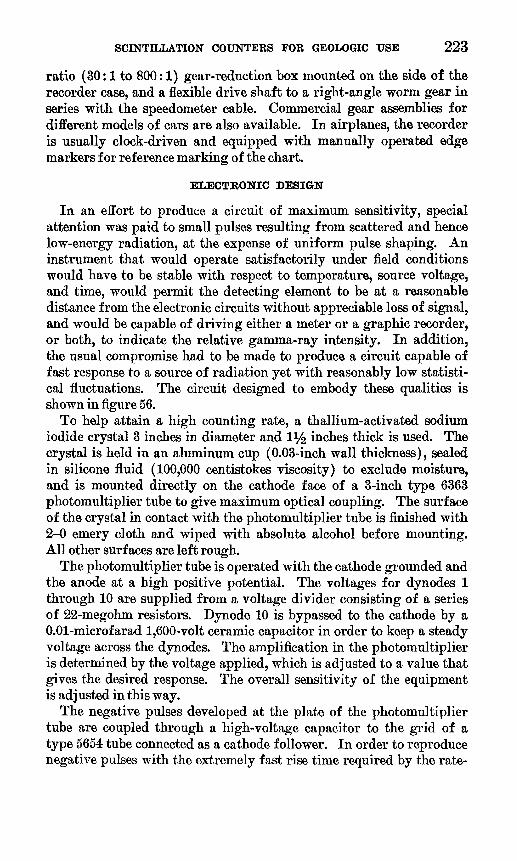
GEOLOGICAL SURVEY BULLETIN 1052 PLATE 11
PORTABLE SCINTILLATION GAMMA-RAY WELL-LOGGING INSTRUMENTS


SCINTILLATION COUNTERS FOR GEOLOGIC USE 233
on a reel of light construction. Two versions of the instrument are shown in plate 11.
The design of a suitable reel is, to a large extent, a matter of personal choice. Only a few aspects are troublesome. The miearta-insulated vertical slip-ring assembly is enclosed in a cast-aluminum housing and sealed with felt washers. Each slip ring has three spring-loaded, wiping contacts. The contacts and slip ring are made of brass; after being "run in" on a lathe, the noise level of this moving connection is below the noise level of the photomultiplier tube. Two drives for the reel are usually provided, one driving the reel directly, the other with a mechanical advantage of about four. A metering wheel located on a tripod over the bore hole, or directly on the reel frame, provides a direct means of measuring the hole depth by reading a revolution counter geared to the wheel. The metering wheel also provides a means of driving the chart movement of the recorder, providing a con tinuous log of radioactivity in the bore hole. The diameter of the metering wheel is cut to give a convenient relation between the ad vance of the chart per foot of hole logged. The error in depth meas urement is surprisingly small usually less than 0.1 percent.
The probe has an outside diameter of 1% inches and is approx imately 14 inches long. Contained within the probe are the photomultiplier tube and dynode voltage dividing system, the thal lium-activated sodium iodide crystal (l^ inches in diameter and 2 inches long), and one-half of the impedance-matching circuit necessary for transmitting the pulse through the coaxial cable. Figure 62 is a schematic diagram of the circuit in the probe.
The crystal is immersed in silicone fluid (200,000 centistrokes vis cosity) in an aluminum cup with 0.020-inch wall thickness and is spring loaded against the window of the photomultiplier tube. The silicone fluid provides optical coupling between the surface of the crystal and the cathode of the photomultiplier. The photomultiplier is shielded magnetically. The part of the aluminum cup containing the sodium iodide crystal extends beyond the magnetic shield. The skirt of the cup fits over the glass envelope of the photomultiplier tube and makes possible a firm connection between tube and crystal. The entire assembly crystal, photomultiplier tube, socket, magnetic shield, and matching circuit is fitted snugly into the probe shell. The probe is then sealed and made waterproof by a pressure gland consisting of three O-rings with a compression nut. A probe with a brass shell of 0.030 inches wall thickness was tested for strength in a triaxial kerosene-filled pressure chamber and collapsed at 600 psi.

234 EXPERIMENTAL AND THEORETICAL GEOPHYSICS
RG59/U
Nal crystal
FIGURE 62. Circuit diagram of the scintillation probe.
The amplifier-ratemeter, high-voltage supply, driving circuit for the recorder, the surface part of the matching circuit, and the battery complement are contained in a suitable case attached to the back of the recorder. The external controls are the on-off, range, and time- constant switches, and the zero and sensitivity controls. The case is sealed against moisture and dust for use under the adverse conditions common to logging.
ELECTRONIC DESIGN
The sensitivity of the probe is such that when placed in a field of 1 milliroentgen per hour of radium gamma rays, a minimum of 300,000 counts per minute will be recorded. Much higher counting rates are possible, but the value quoted here is a compromise which is necessary if a number of instruments are to be made uniform in response and the calibration maintained over a long period of time.
The electrical impulse from the photomultiplier tube is fed into the coaxial cable through the 1000:1 impedance-matching transformer, T! (fig. 62). The coaxial cable has a characteristic impedance of 73 ohms, a capacity of 21 micromicrofarads per foot, is insulated for 2,300 volts, and has an attenuation constant of 3.8 decibels per 100 feet at 100 megacycles. A second impedance-matching transformer, Ta (fig. 63), identical to TI and electrically reversed, is located in the ratemeter at the surface. The pulse at the high-voltage side of trans former Tz is in the form of a damped oscillation; however, the

SCINTILLATION COUNTERS FOR GEOLOGIC USE 235

236 EXPERIMENTAL AND THEORETICAL GEOPHYSICS
damping factor is large enough so that only the first wave will trigger F-l.
The high voltage is connected to the dynode system of the photo- multiplier tube through the same electrical path matching trans formers and coaxial cable that returns the electrical impulse to the counting ratemeter. The high-voltage oscillator tube (F-4) is a sub- miniature tetrode type CK-526-AX. F-4 is triggered by a sawtooth voltage provided by a relaxation oscillator consisting of NE-2, a 0.005-microfarad condenser, and a 5-megohm resistor. The frequency of oscillation is approximately 100 cycles per second and can be con trolled by adjusting either the value of the 0.005 microfarad capacitor or the 5-megohm resistor. The high voltage, which is affected by the frequency of oscillation, is generated by the inductive kick in the choke when the current in F-4 ceases abruptly. This voltage is rec tified and regulated. The high-voltage supply used in the scintilla tion gamma-ray well-logging instrument has 2 regulator tubes (F-6 and F-T) which regulate at 1,200 and 900 volts respectively. The de sired voltage is selected by an external high-voltage selection switch at the amplifier-ratemeter. The 1,200-volt setting is used for high sensitivity, when low-level activity is measured, while the 900-volt setting is used for logging bore holes containing ore-grade materials. The high voltage can be adjusted over a range of 120 volts by the high-voltage adjustment control. This control of counting rate by adjusting the high voltage along with an adjustment of the input sensitivity control on the instrument makes possible a wide range of sensitivity. Therefore, the instrument can be used for logging ore- grade materials with the same linearity and reproducibility as in log ging for stratigraphic correlation. Linearity and reproducibility are extremely important when the instrument is to be calibrated for quan titative measurements.
The ratemeter proper is essentially analogous to the circuit de scribed earlier (fig. 55). A 1-milliampere recorder is driven by tho potential developed across the resistance in the cathode circuit and F-3. The circuit dead time of the trigger pair is approximately 8 microseconds, the pulse time 4 microseconds. Four ranges are cali brated for full-scale readings of 0.04, 0.12, 0.4, and 1.2 milliroentgens per hr (unscattered radium gamma rays). These readings correspond respectively to 12,000, 36,000,120,000 and 360,000 counts per minute. The two potentiometers for adjusting the electrical zero and instru ment sensitivity are controlled externally. Two time constants (1 and 5 seconds) are normally available. The 1-second time constant is commonly used. It is possible to reduce the time constant to 0.2 sec ond by modifying the circuit. With such a fast time constant and a logging speed of 5 feet per minute, 90 percent of a maximum reading

SCINTILLATION COUNTERS FOR GEOLOGIC USE 237
may be recorded during the interval needed for the probe to travel about %-inch. Such rapid response is not normally needed in a port able logging instrument. For all practical purposes, the record of radioactivity as a function of depth is not significantly affected by variations in logging speed of a foot or two per minute when the 1-second time constant is used.
CALIBRATION
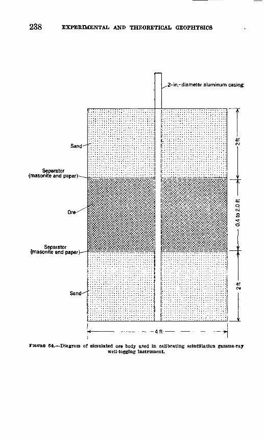
In order to use the equipment to its full capabilities it should be calibrated in terms of grade and thickness of the ore. Although sev eral methods have been attempted, the simplest and most accurate involves the use of simulated drill holes (fig. 64). The holes can be built up in corrugated-iron culvert liners not less than 4 feet in diam eter. An aluminum casing of about 16-gauge thickness is used in the hole. In our calibration procedure, the ore thickness was varied from 0.4 to 2.0 feet. Several grades of radiometrically analyzed ore in the 0.01-1.0 percent equivalent uranium range were used.
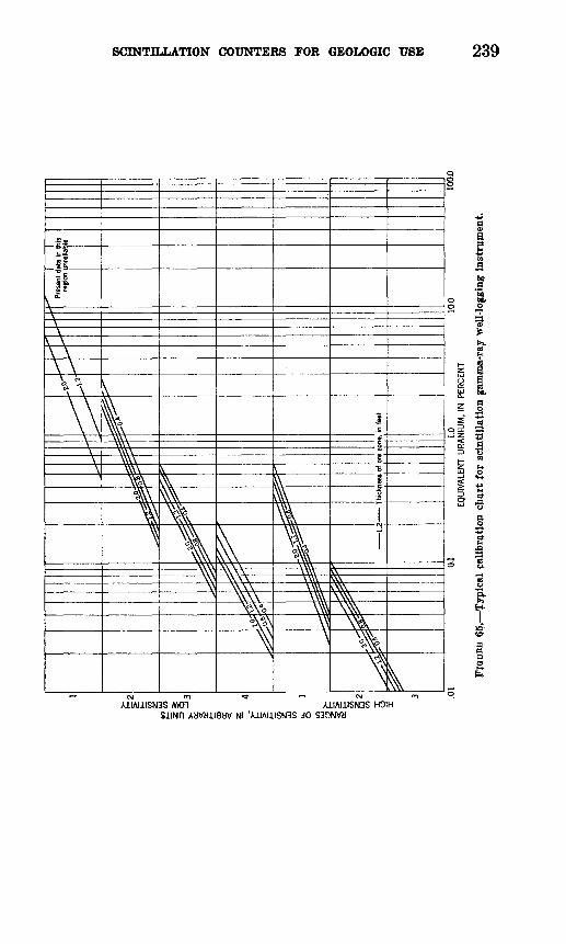
Each grade and thickness combination was logged approximately 25 times in order to obtain a mean value. The results are shown in figure 65.
In order to use the calibration chart to determine the grade of material in an exploratory drill hole, it is necessary to know the height of the deflection registered on the chart and assume the thickness of the postulated ore layer. An indication of the thickness of the mate rial, for layers more than a few inches thick, is obtained by measuring the width of the peak at approximately 70 percent of the maximum deflection.
Field experience with the described equipment has shown that the fast time constant and a logging speed of 10 feet per minute will give very good results for both determining lithology and estimating grade and thickness of radioactive material. In order to maintain the cali bration in the field, a radioactive source should be carried with the instrument and the instrument response to the source at fixed geometry should be checked daily. In this way any drift due to battery fatigue will be recognized and the batteries can be replaced or the necessary adjustments can be made to compensate for the drift.
238 EXPERIMENTAL AND THEORETICAL GEOPHYSICS
2-in.-diameter aluminum casing.
Sand
Separator (masonrte and paper)
Separator {masonite and paper
Sand
FIGCBB 64. Diagram of simulated ore body used In calibrating scintillation gamma-raywell-logging instrument.
2 .01
^§^
,Y>
0.1
1.0
EQUI
VALE
NT U
RANI
UM, I
N PE
RCEN
T
§5.
Typ
ical
cali
bra
tion
cji
art
for
scin
till
atio
n g
amm
a-
*
\ \
Pres
ent d
ata
in t
his
regi
on u
nrel
iat l
e
10.0
100.
0
ray
wel
l-lo
ggin
g in
stru
men
t.
1 s O
H
Q CO

240 EXPERIMENTAL AND THEORETICAL GEOPHYSICS
SELECTED BIBLIOGRAPHY
Brownell, G. M., 1950, Radiation surveys with a scintillation counter: Econ. Geology, v. 45, p. 167-174.
Davis, F. J., Barter, J. A., Reinhardt, P. W., and Harris, D. F., 1954, Scintilla tion detector for carborne and airborne use: Nucleonics, v. 12, no. 12, p. 46- 47.
DiGiovanni, H. J., Graveson, R. T., and Yoli, A. H., 1953, Scintillation unit for drill-hole logging: Nucleonics, v. 11, no. 4, p. 34-39.
Eichholz, G. G., Hilborn, J. W., and McMahon, C., 1953, The determination of uranium and thorium in ores: Canadian Jour. Physics, v. 31, p. 613-628.
Faul, Henry, 1948, Radioactivity exploration with Geiger counters: Am. Inst. Min. Metall. Eng. Trans., v. 178, p. 458-478.
1950, Radioactivity methods; in Jakosky, J. J., (editor) Geophysical pros pecting : Los Angeles, Trija Publishing Co., p. 987-1015.
Hurley, P. M., 1956, Direct radiometric measurement by gamma-ray scintillation spectrometer: Geol. Soc. America Bull., v. 67, no. 4, p. 395-412.
Nelson, J. M., 1953, Prospecting for uranium with car-mounted equipment: U. S. Geol. Survey Bull. 988-1, p. 211-221.
Peirson, D. H., 1951, Alpha particle assay and the measurement of the thorium- uranium ratio in radioactive ores: Phys. Soc. (London) Proc., sec. B, v. 64, p.876-888.
Pringle, R. W., Roulston, K. L., and Brownell, G. M., 1950, Ultrasensitive portable gamma-ray spectrometer: Nature, v. 165, no. 4196, p. 527.
Rajewsky, B., 1943, Das Geiger-Miiller Zahlrohr im Dienste des Bergbaues [The Geiger-Mtiller counter applied to mining]: Zeitschr. Physik, Band 120, p. 627-638.
Ridland, G. C., 1945, Use of the Geiger-Miiller counter in the search for pitch blende-bearing veins at Great Bear Lake, Canada: Am. Inst. Min. Metall. Eng. Trans., v. 164, p. 117-124.
Schmitt, O. H., 1938, Thermionic trigger: Jour. Sci. Instruments, v. 15, p. 24-26.Slack, H. A., 1949, Radioactivity measurements in the Kirkland Lake area,
northern Ontario, Am. Geophys. Union Trans., v. 30, no. 6, p. 867-874. 1952, The application of recent counting techniques to geophysical re
search Part I, Field measurement of the radioactivity of rocks: Am. Geo phys. Union Trans. v. 33, no. 6, p. 897-901.
Slack, H. A., and Whitham, K., 1951, A further investigation of the radioactivity of the Round Lake and Elzevir batholiths: Am. Geophys. Union Trans., v. 32, no. 1, p. 44-48.
Tittle, C. W., 1954, Gamma-ray and neutron logging in the petroleum industry, in Faul, H., (editor), Nuclear geology: New York, John Wiley and Son, p. 241-250.
O