Embed Size (px)
Citation preview
,I j
PROPOSAL No. ~ I i l' I \
Scientific Spokesman: i ~ j
James K. Walker :1 ! Fermi National Acce1erat:of Lab P.O. Box 500 ;
!
I
Batavia, Illinois 60510
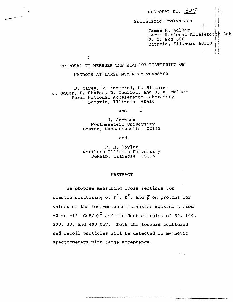
PROPOSAL TO MEASURE THE ELASTIC SCATTERING OF
HADRONS AT LARGE MOMENTUM TRANSFER
D. Carey, R. Kammerud, D. Ritchie, J. Sauer, R. Shafer, D. Theriot, and J. K. Walker
Fermi National Accelerator Laboratory Batavia, I~linois 60510
and
J. Johnson Northeastern University
Boston, Massachusetts 02115
and
F. E. Taylor Northern Illinois University
DeKalb, Illinois 60115
ABSTRACT
We propose measuring cross sections for
+ + elastic scattering of n-, K-, and p on protons for
values of the four-momentum transfer squared t from
-2 to -15 (Gev/c)2 and incident energies of 50, 100,
200, 300 and 400 GeV. Both the forward scattered
and recoil particles will be detected in magnetic
spectrometers with large acceptance.

TABLE OF CONTENTS
I. Introduction
II. Physics Objectives and Justification
III. Experimental Method
A. General
B.. Recoil Spectrometer
c. Forward Spectrometer
D. Trigger
IV. Beam Requirements
V. Elastic Rates
VI. Backgrounds
A. Quasi-Elastic N* Production
B. Singles Rates
C. Trigger Rate
VII. Time Request
VIII. Fermi1ab Request
IX. Proposed Schedule
X. Additional Experimental Possibilities
A. Backward Elastic Scattering
B. Inclusive Reactions
APPENDIX I Magnetic Parameters and Cost Estimate
APPENDIX II Electronic Data Filter and Processor
Description
Page
1
2
6
6
8
10
12
14
15
16
16
17
19
21
22
23
23
23
24
26
28
-1
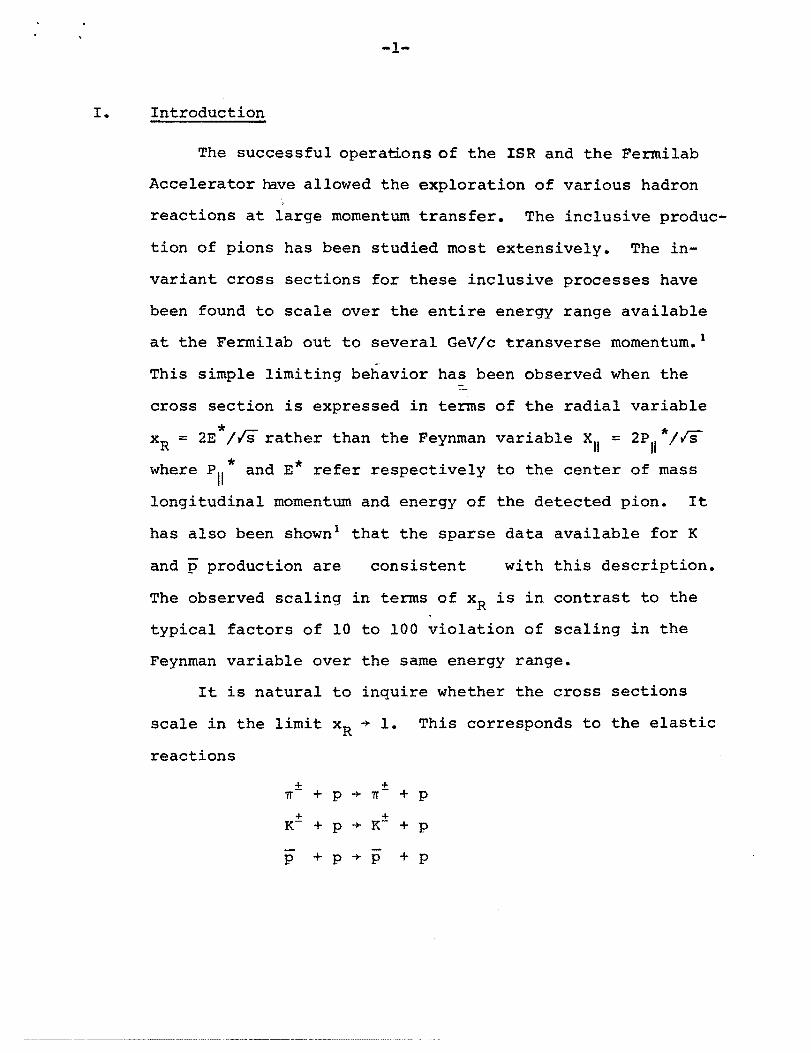
I. Introduction
The successful operations of the ISR and the Fermilab
Accelerator have allowed the exploration of various hadron
reactions at large momentum transfer. The inclusive produc
tion of pions has been studied most extensively. The in
variant cross sections for these inclusive processes have
been found to scale over the entire energy range available
at the Fermilab out to several GeV;c transverse momentum. l
This simple limiting behavior has been observed when the
cross section is expressed in terms of the radial variable
= 2E *;IS rather than the Feynman variable Xu = 2P *;rsxR U
where P * and E* refer respectively to the center of massII
longitudinal momentum and energy of the detected pion. It
has also been shown l that the sparse data available for K
and p production are consistent with this description.
The observed scaling in terms of xR is in contrast to the
typical factors of 10 to 100 violation of scaling in the
Feynman variable over the same energy range.
It is natural to inquire whether the cross sections
scale in the limit xR + 1. This corresponds to the elastic
reactions
p + p + p + P
------- -- ---~---~--------------~ ---.............---~-----------~---.-.------.- .._- -~~--------~---- ---

-2
These reactions are completely unexplored at large momen
tum transfer (It I > 2) and high energy. The experimental
results on inclusive pion production demonstrate the im
portance of making the elastic measurements over the largest
possible energy range at large fixed momentum transfer.
II. Physics Objectives and Justification
The purpose of this experiment is to measure the + +
elastic scattering of ~-, K-, pat 50, 100, 200, 300 and
400 GeV for It I ~ 2 (Gev/c)2. The upper limit of momentum
transfer will be determined by the counting rate and the
lower limit (which could be less than 2 (Gev/c)2) by the
desire to provide a region of overlap with existing data.
Experiment 7 (Meyer et a1.) presently has data out to
It I > 1 (Gev/c)2 and expect to approach It I = 2 (GeV/c)2.
The lower limit of the elastic cross section which
will be able to be measured will be less than 10-36 cm2
/(GeV/c)2 and the experiment will be able to place an upper
limit to the cross section at large It I of - 10- 37 cm2
/(GeV/c)2. The energy dependence of the elastic cross sec
tion, da/dt at fixed It I follows a power law behavior2 s-n
(where n depends on Itl). The value of n decreases as s is
is increased (Fig. 1) until the cross section scales. How
ever, at ISR energies the pp elastic cross section at It I
~ 2 (Gev/c)2 dramatically changes its character and begins to
rise although at this time the statistics are poor. The
-3
increase in cross section appears to be about a factor
of 2 over the ISR energy range. 3 These preliminary re
sults are shown in Fig. 2. This behavior was predicted
in 1972 within the context of the Impact Picture~ and is
connected with the rising proton proton total cross
section. More generally, the s dependence of the
elastic cross section provides model independent informa
tion on the impact parameter range which is responsible
for the increasing total cross sections.
+As the K p total cross section starts to rise
already at 20 GeV this channel is of great interest
in providing the cleanest means of studying the
mechanisms involved in the phenomenon of rising cross
sections. It is likely that the kaon-nucleon elastic
cross sec ion at large momentum transfer is quite large
and will therefore be relatively easy to measure. The
simplest way to see this is by observing that the Kp
total cross section is small, 20 rob, compared to 30 rob
and 40 rob for TIp and pp respectively. This implies that
the kaon probably is quite a small object compared to
the pion and nucleon and this will result in a larger
scattering cross section at large momentum transfer.
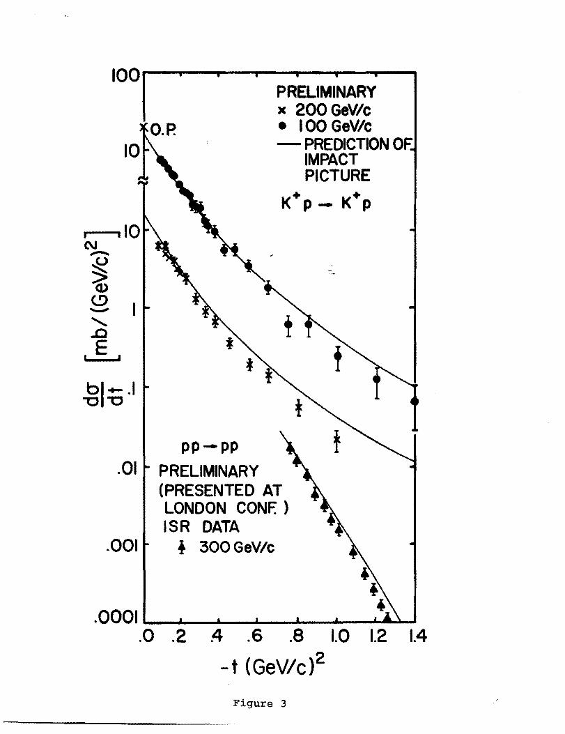
Figure 3 shows the predictionS of the Impact Picture for
K+P elastic scattering and the preliminary data of Exp. 7.
Already at It I = 1 there is a strong suggestion that
the Kp cross section is becoming much larger than the pp
cross section. Figure 4 shows the predicted pomeron
contribution to each elastic cross section in the range
o ~ It I ~ 10 (GeV/c)2.

-4
For s > 600 GeV2 the pp predictions are in good
agreement with the ISR data out to It I ~ 4(Gev/c)2. The
predicted Kp cross section flattens out at large It I
and is about 10-36 cm2/(Gev/c)2 at It I ~ 20 (GeV/c)2.
Although these Kp estimates may be somewhat optimistic
they do raise the definite possibility of making measure
ments out to enormous momentum transfer.
We therefore take note of the following:
1. The Kp channel may have more than a
thousand times the cross section of
the other channels at large Itl.
Although the K content of the beam
is expected to be rather small (K/~
N .1) it is possible that
the number of scattered kaons will
be large relative to pions. This is
in distinct contrast to the situation
for single particle inclusive produc
tion at large PJL where the kaons are
less numerous than pions. For this
reason we propose to have full ~-K
separation of the scattered particles
in order to obtain an initial survey of
the cross sections. Based on the
results of the survey we will respond
to any large particle ratios by adding
additional particle identification if
necessary.
- -
-5
2. The spectrometer system should be
physically able to measure to a It I
of at least l5(GeV/c)2.
3. There will probably be significant
s-dependencies of the "asymptotic"
cross sections, dcr/dt, as in the pp
channel. To study this will require
measurements over the largest possible
energy range.
We now summarize the physics objectives of this
experiment. We shall measure the elastic cross sections
for the processes
± ± 1T + P + 1T + P
+ +K- + K+ P + P
+ + PP + P P
from 50 to 400 GeV, It I ~ 2(GeV/c)2. The lower limit
of cross section which will be measurable will be
about 10-37 cm2/(Gev/c)2. These reactions "are of
fundamental importance. They will provide information
on the mechanism of rising total cross sections. In
addition, many model predictions (parton etc.) exist
which try to relate the strong interaction dynamics
of inclusive particle production and elastic scattering
in the high momentum transfer region. The data obtained
from this experiment together with the available
-6
inclusive data will provide stringent constraints
for such models.
III. Experimental Method
A. General
Our objective is to be sensitive to the lowest
possible cross sections. For this purpose we need
to use the highest beam intensity available, a long
target and have the largest possible detector acceptance.
The importance of the latter requirement is greatest
for 300 and 400 GeV running because of the decreasing
particle flux in the beam. For this reason we have
designed our spectrometers to have a very large acceptance.
At the same time, however, we have taken care to ensure
that detectors are located in such a way that their
instantaneous singles counting rates are acceptable.
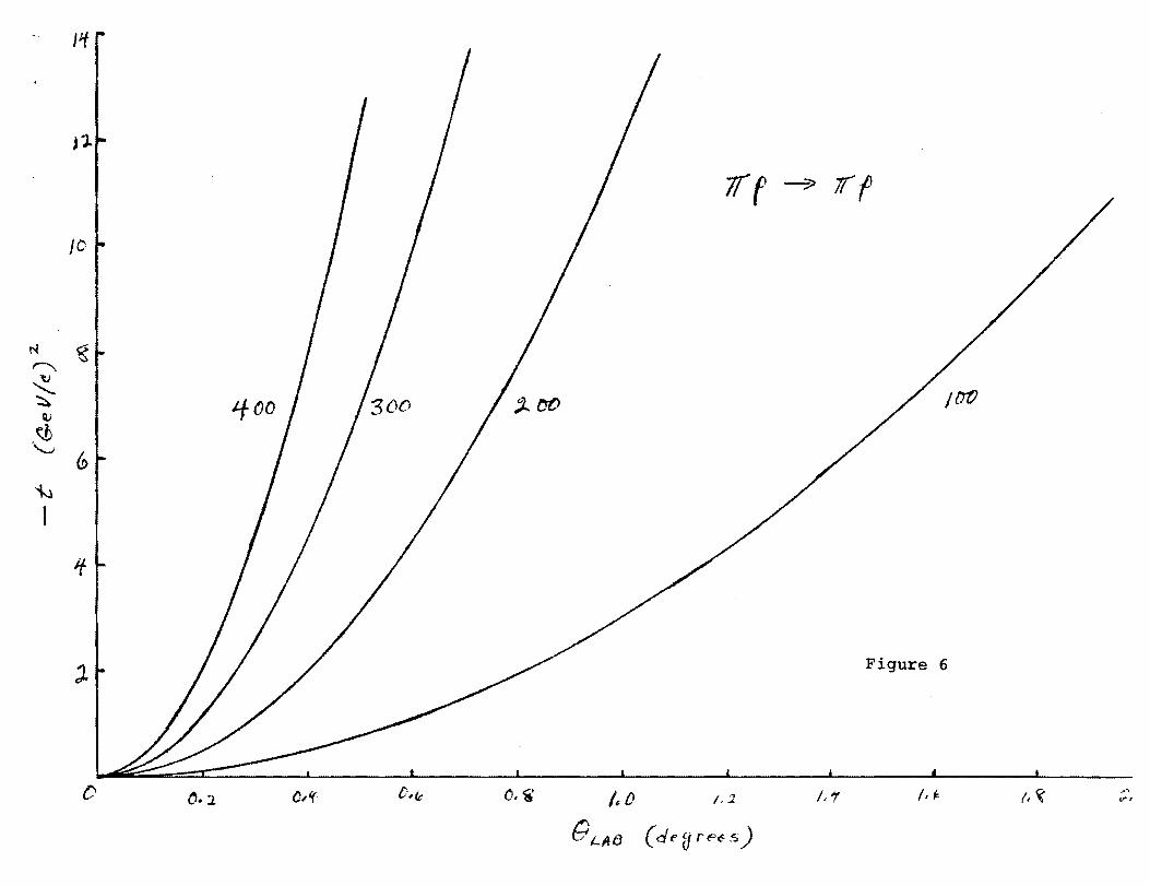
Figures 5 and 6 show the Laboratory angles of the
recoil proton (approximately independent of incident
beam particle species and momentum) versus It I and the
angle of the fast forward scattered particle versus Itl.
Given that a major part of the running for the experiment
is required for the largest Itl measurement we have
chosen to design our magnet spectrometers with very large
~ acceptance and at the same time have a large ~t accept
ance at large Itl. In fact, the recoil proton is detected
with high efficiency in the range 5.7 ~ It I ~ 12.7 (Gev/c)2
in a single setting with a ~~ acceptance of 300• This

300
-7
Itlacceptance transforms to ~eHor = 0.370 and ~¢Vert. =
for the forward scattered particle at 200 GeV/c
incident energy. The small geometric acceptance for the
forward scattered particle is of help not only in limiting
the cost of the forward magnets but in keeping to a rea
sonable radius the very long Cerenkov counters required
for momenta above 200 GeV. In addition, we can see from
Fig. 6 that if we scale distances proportional to energy
for the forward spectrometer then~~e maintain full
acceptance over the energy range 50-400 GeV.
The measurements will be made using an intense
(- 109 particles/sec) unseparated secondary beam of
hadrons produced from a primary proton beam of up to
500 GeV/c. This beam intensity precludes counting in
the incident beam. The liquid hydrogen target will be
16" long.
Elastic events will be defined by measuring the
momentum and angle of both particles in the final state
using magnetic spectrometers. This provides a one
constraint fit for eiastic scattering even though no
measurements are made in the incident beam. The forward
scattered particle will be identified with Cerenkov
counters. Figure 7 shows a layout of the two spectrom
eters.
The momentum resolution in the forward arm will
be ~ ± 1% or better in all cases and ~ ±1.5% in the
recoil spectrometer. The recoil arm will have an angular

'-8-
resolution of ± 2.5 mr, and the forward arm an angular
resolution of ± .25 mr at 100 GeV and proportionately
better at the higher energies. These provide quite adequate
t resolution e~t/t S .03), and enable tight kinematic
constraints to be made to reject backgrounds.
B. Recoil Spectrometer
Recoil protons will be analyzed using a magnet which
bends trajectories in the vertical plane (see Figure 8).
Proportional wire chambers will be located behind the
magnet. A trajectory will be defined by the chambers
behind the magnet together with the line source defined by
the beam in the target. This magnet will have a 15 Kg
field and will be 60" long, with a 24" pole width and a
15" gap. To enable this magnet to be as close as possible
to the target at the small angles e- 300 for It I = 10
(Gev/c)2), the incident beam passes through a slot in one
of the pole pieces. Tbe effect of the pole piece slot on
the magnetic field is slight. The coils are carried
around on the other side of the aperture.
Proportional chambers PI' P2 will have vertical wires
with 3 mm spacing and will be separated by 3 feet. The
angle of the recoil proton is measured to an accuracy of
~ep = ± 2.4 mr. Proportional chambers P3 and P4 have
horizontal wires with 2 mm spacing and are used to determine
the recoil momentum. The chambers are separated by 3' giving
a magnet exit angle resolution of ± 1.6 mr.
-9
The hodoscopes HI and H3 have 1" fingers in the
vertical direction and allow measurements of the recoil
proton angle t~ ± 20 mr. Hodoscopes H2 and H4 have 2"
fingers in the horizontal direction and provide a measure
ment of the recoil proton magnet exit angle to ± 30 mr.
The hodoscope information is used in the trigger as
described later.
This spectrometer, when set at ~ 320 to the beam
line, for the large It I measurement~ has an acceptance of
~ ± 2.50 in the horizontal plane for the entire target
length and a 6~ acceptance of 300 • The target acceptance
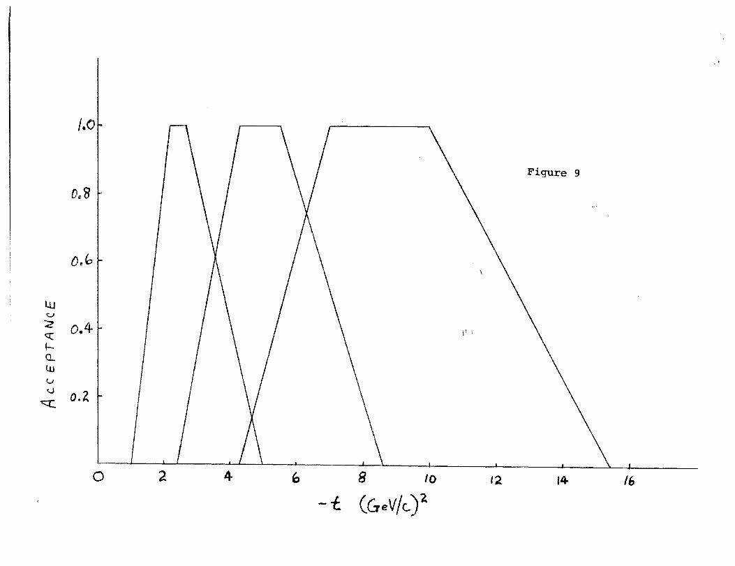
of the spectrometer as a function of It I is shown in Fig.
9. Three settings will be required to cover the full
range 2 ~ It I ~ 12.7 (GeV/c) 2 with a 6~ acceptance of >
200 and a target acceptance of ~ 60% for all Itl. The
acceptance over the entire It! range varies by ~ 4% within
the It I resolution of the spectrometer.
The rms momentum and It I resolutions of the spectrom
eter are summarized in the table below. When we take
into account the ± 1 mr beam divergence, the multiple
scattering of the recoil proton in the target and the
finite target size we obtain:

-10
Reco1"1 S;pectromet er Reso1ut10n
It I 2(GeV/c)
.~
p At t.
2 ± 0.6% ± 1.0%
6 ± 1.2% ± 1.1%
10 ± 1.S% ± 1.2%
c. Forward Spectrometer
The forward scattered particle will be analyzed in
a vertical bending magnet with proportional wire chambers
Ps ' P6 , P7 and Ps in front and P9 and Plp behind the
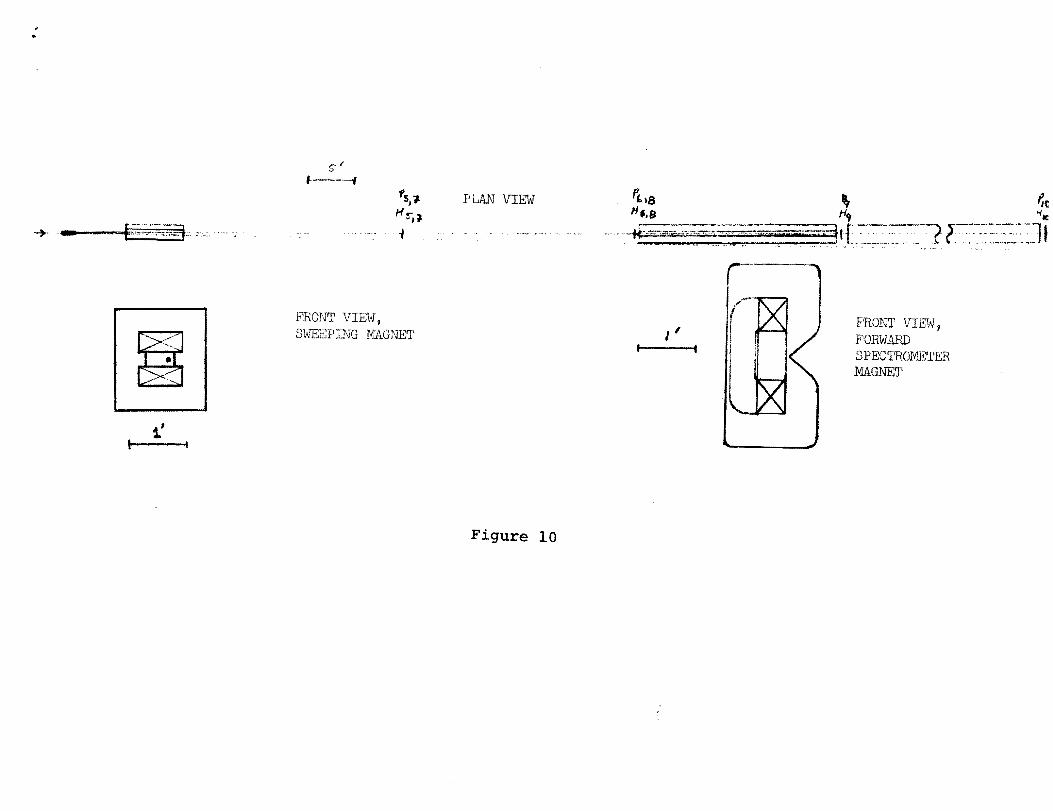
magnet. To sweep (see Fig. 10) lower momentum charged
particles away from the front chambers, a small vertical
bending magnet (- 6" gap x 3" pole width x 72" long)
will be placed close to the target. The line source
defined by the beam in the target together with PS ' P6 ,
P7 and Ps will provide a second momentum measurement.
Although the resolution on this measurement is somewhat
poorer than in the main analyzing system, it will be
helpful in eliminating any pole tip scatters which escape
the other cuts in the trigger and analysis.
The main momentum-analyzing magnet will be 6.5" gap
x 9.5" high x 20' long and will be constructed as shown
in Fig. 10 to allow close enough approach to the beam.
The distance of this magnet from the target will be
scaled to the incident energy, so that the distances
from the beam for fixed It I will remain the same. The

-11
acceptance is matched to that of the recoil arm at large
It I.
The propor,tional wire chambers PS' P6 , P7 , PS' P9 ,
and PIO will have 1 rom wire spacing and permit an rms
angle measurement of ± .2 mr at 100 GeV/c (resolution
scales with energy) and an rms momentum determination
of ± 1%. Hodoscopes HS' and H6 allow a measurement of
the scattering angle to .... ±l mr and H7 and HS measure the
azimuth to ~ 100 • Both of these r,esolutions include the
beam divergence which dominates the estimates. The hori
zontal element hodoscopes H9 and HIO are located behind
the analyzing magnet. The information from the hodoscopes
is used in the trigger as described later.
Threshold Cerenkov counters Cl and C2 are shown in
the 200 GeV configuration in Fig. 7. Counter Cl detects
pions and C2 detects both pions and kaons. Simultaneous
identification of pion, kaon and nucleon scattering can
thereby be achieved. It is quite possible that the
predicted large differences in cross sections will make
the task of particle identification very difficult.
For example if the K/p cross section is indeed > 10 3 at
large It I then a small inefficiency in counter C2 will
give a large error to the nucleon cross section.
If on the other hand, the la.rge differences in
cross section are not found, then the relatively small
K/~ ratio of the beam (- .1) probably prevents measuring

-12
2the K cross section below ~10-35 cm , that is, at the
highest energies and largest Itl. In this case, we need
only identify pions with reasonable efficiency (~ 95%).
The Cerenkov counters shown in Fig. 7 will provide
reliable cross section measurements for both pions and
kaons in either of the above situations. is 65 metersC1 long giving an efficiency for pion detection of €~ ~ 99.9;
C2 has a comparable efficiency for kaons and is 25 meters
long. These efficiencies guarantee that for either extreme,
in relative cross section, the contamination of K's in
the ~ signal or ~'s in the K signal is ~ 3%. This is
certainly adequate and may be relaxed somewhat.
Depending on the results of the early running, we will
add whatever additional particle identification that is
necessary.
D. Trigger
We intend reaching a cross section sensitivity of
~ 10-37 cm2/{Gev/c)2. In a ~t = 1 {Gev/c)2, this
corresponds to about one interaction in every 1011 beam
target interactions being an elastic event. Hence a high
rejection efficiency for background processes is re
quired in the trigger. We propose using a three level
trigger system. The first level employs a fast
-13
coincidence between hodoscopes
and a calorimeteric measurement of the forward energy to
25%.
The second level of the trigger employs a hardwire
matrix coincidence of the hodoscope information. Assum
ing elastic kinematics, coplanarit.y to within ± 50 can
be demanded. In addition, the hodoscope reconstruction
can assure that the tracks in both arms are target
associated. If these requirements are met, the hodo
scope information will be used to mask the proportional
chambers for track finding in the final level of trigger
definition.
In the third and final trigger level, a hard-wired
processor of the proportional chamber outputs will be
employed to make
i) a coplanarity check to ± 30 ,
ii) forward momentum determination
to ± 10%,
iii) recoil angle-momentum correlation
to ± 10%.
The first level trigger signal will be processed
in about 100 ns. The coarse hodoscope logic will require
an estimated 200 ns (roughly the gating time of the
chambers). The last level of the trigger involves track

-14
location within "roads" generated by the hodoscopes
and will require an estimated 1 ~s.
If all three levels of trigger are satisfied then
a master trigger signal will be generated and all counter
and wire. chamber data will be recorded on magnetic tape.
A schematic description of the hodoscope data filter
and proportional chamber processor is given in Appendix
II, and their effect on the trigger rate is outlined in
Section VI.
IV. Beam Requirements
The highest possible beam intensity is required
within the constraints given below. Our detection system
is designed to be able to accomodate 109 incident particles/
beam pulse.
The vertical beam spot size should be ~ 2 mm so as
not to degrade the momentum resolution of the recoil arm.
The vertical beam divergence should be kept to ± 0.4 mr
at 100 GeV and proportionately less at higher energy
to maintain the resolution in coplanarity for It I < 5
(GeV/c) 2 • The divergence can be increased to ± .6 mr for
the large It I measurements at full beam intensity. The
horizontal divergence should be less than ± 0.5 mr for
the measurements with reduced beam intensity at low Itl.
However, for measurements at the largest It I values which
require maximum beam flux we can take a horizontal beam
divergence of ± 1 mr.

-15
V.ElasticRates
The rate of elastic events is
1014Nn = beam flux = 1.2 x (300 hours, 9 sec. rep.
rate, 109 n/pu1se
Np = target protons =,16.8 x 1023 (16" LH2)
~¢ = azimuthal acceptance = 3Q~
At the cross section limit of 10-37 cm2/(Gev/c)2
we obtain - 2 events/(GeV/c)2.
If we take as an estimate of the cross sections
the lower limits predicted by the Impact
Picture as shown in Fig. 4 then we expect to measure
the np cross sections to a It I of at least 5 (GeV/c)2
at the highest energy and to It I of at least 15 (Gev/c)2
for the kaons at all incident momenta.
The following table shows the predicted rates
based upon the impact picture estimate of the minimum
cross section (i.e. pomeron contribution only) that
will be observed. This assumes a beam intensity of
109 pions/pulse (4 x 10¹¹ n/hour and K/n=.l.

-16
MINIMUM EXPECTED RATES
t (GeV/c) 2
£\4>
dcr/dt cm2/(Gev/c) 2
1Tp kp
Time (Hours)
Yield/2(GeV/c) 1Tp kp
2.5 200 lxlO-33 8xlO-3l 100 4,000 320,00C
5.0 25 0 2xlO-36 lxlO-32 200 20 10,000
8.5 300 6xlO-39 5xlO-34 300 800
Due to the expected small number of p I;S in the beam
(p/1T - 10-2) pp elastic cross section will be measured
only to _ 10-34 cm2/(Gev/c)2.
VI. Backgrounds and Trigger Rate
The major background contaminations in the trigger
of the proposed experiment are expected to result from
quasi-elastic N* production and from random coincidences.
The rates and system acceptance for these backgrounds is
outlined below.
A. Quasi-Elastic N* Production
Events of the type 1Tp ~ 1TN* most nearly simulate elastic
kinematics and will certainly provide acceptable triggers.
Kinematically, this is most severe for the higher mass N*'S
decaying in the production plane. The integrated diffrac
tive inelastic cross section is known to be comparable to
the elastic cross section. However, if we assume pessimisti
cally that the N*'s, which appear to be produced in a

-17
diffractive fashion at low energy, individually have produc
tion cross sections at 2 ~ It I $ 6 (Gev/c)2 comparable to
the elastic cross section, then we will observe a somewhat
greater number of N* events than elastics in the first
level of the trigger. Less than 20% of the quasi-elastic
events will satisfy the coplanarity and recoil angle-
momentum correlation cuts in the third level of the
trigger. The expected master trigger rate for this type
of event is therefore comparable~~o or less than the
elastic rate.
The angular and momentum resolutions of the recoil
spectrometer are adequate to separate the decay proton
from an elastic proton in the offline analysis for all but
a small region of c.m. decay angles for the N* (for
example, 69 cm - 200 for the N* (1520)) and a small region
in azimuthal angle of the decay plane (69 - 400 ). Based
upon these considerations, we expect to observe roughly
1% of the N* decays which are kinematically inseparable
from elastic scatters within the system resolution.
Assuming the integrated N* production cross section is
comparable to the elastic cross section in this It I interval, we expect that the contamination will be about
1% in all cases and will simultaneously be measured in
the kinematic region outside the elastic peak. This will
allow a reliable subtraction to be made.
B. SinglesRates
Estimates of the single particle rates in the counters
-18
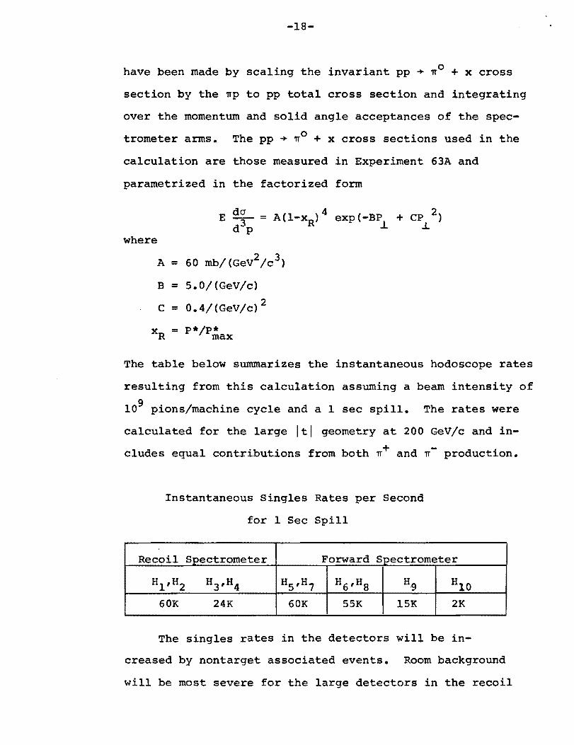
have been made by scaling the invariant pp + nO + x cross
section by the np to pp total cross section and integrating
over the momentum and solid angle acceptances of the spec
trometer arms.. The pp + nO + x cross sections used in the
calculation are those measured in Experiment 63A and
parametrized in the factorized form
where
A = 60 mb/(Gev2/c3)
B = 5.0/(GeV/c)
C = 0.4/(Gev/c)2
X = p*/p*R max
The table below summarizes the instantaneous hodoscope rates
resulting from this calculation assuming a beam intensity of
109 pions/machine cycle and a 1 sec spill. The rates were
calculated for the large It I geometry at 200 GeV/c and in
cludes equal contributions from both n+ and ~- production.
Instantaneous Singles Rates per Second
for 1 Sec Spill
Recoil Spectrometer Forward Spectrometer
Hl ,H2 H3,H4 H5 ,H7 H6 ,H8 H9 HIO 60K 24K 60K 55K 15K 2K
The singles rates in the detectors will be in
creased by nontarget associated events. Room background
will be most severe for the large detectors in the recoil

-19
spectrometer. These effects will be reduced to a tolerable
level by shielding.
Secondary target backgrounds will be most severe in ,
the forward arm where the solid angle subtended by the
detectors from the target is small relative to the solid
angle of the possible secondary targets. The most serious
secondary targets will be the recoil spectrometer magnet
structure, the beam pipe and the sweeping magnet poles.
The sweeping magnet in the forwar~ spectrometer will
shield the detectors quite well from the recoil magnet
structure. It may be desirable to use a helium bag instead
of a beam pipe between the target and downstream detectors.
Pole tip scatters in the forward spectrometer will certainly
increase the singles rates in the detectors. This could
provide an increase in singles rates by as much as a factor
of S or 10 in HS' H6 , H7 and H8- We do not expect a
correspondingly large increase in the detectors H9 and H10
behind the analyzing magnet due to the large sweeping
power of this magnet and the dominance of low momentum
secondaries resulting from the pole tip scatters. Thus,
no counter is expected to operate at more than about 0.5
megacycle per second instantaneous rate.
c. TriggerRate
The trigger rate (at any level of the trigger) will
consist primarily of elastic scatters, quasi-elastic
production and random coincidences. As discussed in part

-20
A of this section, we expect the quasi-elastic rate satis
fying the full trigger to be comparable to or less than
the elastic rate. We shall now estimate the random coin
cidence rate for the trigger.
The rate of random coincidences between the hodoscopes
in the recoil and forward spectrometers is determined by
the rates of particles traversing the complete set of detec
tors in both spectrometers. As discussed in Section B above,
these rates will be dominated by the single particle inclu
sive rates and are 24 K and 2 K respectively. Assuming a
10 ns resolving time we will therefore obtain NO.5 random
coincidences/machine cycle. The three level trigger system
will reduce this to about 0.1 random master trigger/hour.
This has been estimated in the following way.
Less than 30% of the random coincidences among the
hodoscopes will satisfy the calorimetric energy measure
ment in the forward spectrometer. Thus -0.13 randoms/pu1se
will satisfy the first level of the trigger.
In the second trigger level N30% of the randoms will
satisfy the cop1anarity cut (-0.04/pu1se). In addition,
at this level most nontarget associated tracks will be
eliminated.
In the third and final level of the trigger 40% of the
randoms will survive the coplanarity cut and assuming a
momentum distribution -exp(-5.0 P ) in both spectrometers,L
a further reduction by at least a factor of 50 is
realized in the momentum cuts and the angle-momentum
-21
correlation in the recoil spectrometer. We then expect
~O.l random master trigger/hr which is quite satisfactory.
The master trigger rate is therefore dominated by at least
a factor of a thousand by elastic and quasi-elastic scatter
ing at the large It I setting.
VII. Time Request
We propose to divide the experiment into two phases.
In the first phase (Phase I) we will study + +
a) the It I dependence of the 'IT-P, K-p and pp
elastic cross section for 2 ~ It I ~ 12.7
(GeV/c)2 at 200 GeV. As indicated in the
yield calculation, this will require 600
hours of beam.
In addition, we will investigate
b) the s dependence of these cross sections
by obtaining data at 100 and 400 GeV in
the interval 3.5 ~ It I ~ 7.0 (GeV/c)2.
Less than 200 hours will be required at each of these two
energies. The total time required to perform these
measurements is then ~ 1000 hours. We will also require
200 hours for testing and tuning.
Based upon the results of the Phase I experiment we
will request time for Phase II. There we will perform a
more detailed study of the s dependence of the cross sec
tions by running at 50, 100, 300, and 400 GeV/c for momen
tum transfers up to the largest It I that the rates permit.

-22
In summary, the Phase I running time request is
Secondary Beam Energy H.ours of Beam Time
100 GeV
200 GeV
400 GeV
200 hours
600 hours
200 hours
together with 200 hours of tune up time.
VIII. FermiLab Requirements
We propose that the items listed below be provided by
the Laboratory research facilities.
1. Liquid hydrogen target 16" long.
2. Three magnets and the associated
mechanical support systems.
Approximate design characteristics
and cost estimates for the magnets
are given in Appendix I.
3. PREP electronics.
4. Computer and Porta Kamp.
5. Shielding and collimation as necessary.
The Physics Departments of FermiLab, Northeastern Univer
sity, and Northern Illinois University will provide
1. Beam Monitors
2. Cerenkov counters
3. Scintillation counters

-23
4. Proportional chambers
5. Hardwire data processors (Appendix II)
IX. Proposed Schedule
From the time of approval of this proposal we can have
the apparatus assembled and ready for preliminary testing
in 18 months. No technological development work is required
for any of the apparatus~ the design is straightforward and
can be done now. We believe that the high momentum transfer
elastic scattering results obtaine.d through this experiment
will be crucial to our understanding and progress in strong
interactions. For these reasons, i.e. a) fundamental physics
interest and b) technological straightforward design, we
request prompt action and support of this proposal.
X. Additional Experimental Possibilities
The spectrometer system proposed here is well suited to
experiments other than the large It I elastic scattering. Two
of the more interesting possibilities are discussed briefly
below.
A. Backward Elastic Scattering
With the addition of a short Cerenkov counter for parti
cle identification in the recoil spectrometer, the large luI
(1 ~ lui ~ 12 (GeV/c)2) elastic scattering reactions
+ + Ie + p -+- p + K-
p + p -+- p + P
--- ... _._----_.

• • •
-24
can be studied. In fact because mass effects are essentially
negligible at high energy and momentum transfer, our
optimized high It I double spectrometers are also optimal
for the high lui case. The same remarks can be made for
the interesting crossed reactions
p - + P .... 'IT + 'IT+
P + P .... K- + K+
Little is known about the high energy behavior of any
of these cross sections. At large sand u, baryon exchange
amplitudes typically become small so parton effects may
dominate.
Compared to the first generation backward scattering
experiments proposed in the Meson Laboratory this study
would be approximately 1000 times more sensitive in looking
at small cross sections.
B. Inclusive Reactions
The inclusive particle production cross sections in
the reactions
+ X
+ and the corresponding reactions for K- and p projectiles
can be studied at large transverse momentum.

-25
Particle identification would be required in the incident
beam and this would limit the flux to -10' particles/sec.
Beam intensity can be controlled by using particles produced
at a p ~l GeV/c and thereby enhancing the kaon and anti~
proton content of the beam. For 10' particles/pulse we would
obtain about 3 x 10⁶ K/pulse.
The forward spectrometer would be operated in its largest
solid angle position corresponding to about 0.35 msr. This
large solid angle allows the detection of the decay products
of short lived particles such as the $, Kso, etc. In addition,
it is conceivable that useful correlations could be studied
when triggering on specific particles in the forward spec
trometer and using the large aperture second spectrometer to
study the reaction products.
Inclusive cross sections would be measured out to p ~
~ 5 GeV/c and over a large range of center of mass angle.
-26
APPENDIX I
Magnet Parameters and Cost Estimate
The table on the following page shows the basic
design parameters for the three magnets discussed
in this proposal. Based upon these parameters rough
designs have been generated in order to provide an
estimate of the cost of each magnet. The cross sec
tions of the magnets shown in Figures 8 and 10 are
based on this design and some of the pertinent numbers
are included in the following table. The cost
estimates are based on a machined steel price of
$400/ton and a formed copper price of $8/lb. These
estimates do not include assembly cost.
Upon approval of this experiment we will attempt
to locate existing magnets or parts of magnets which
can be adapted for our use. In particular, the sweep
ing magnet geometry is not critical and a suitable
substitute can probably be found. The 20' analyzing
magnet has a larger aperture than the main ring bending
magnets, but it may be possible to modify and use some
of the parts without excessively compromising the
experimental design.

-27
Magnet
Recoil Spectrometer Ana1yzing Magnet
Forward Spectrometer Sweeping Magnet
Forward Spectrometer Ana1y~ ing Magnet
Central Fl.eld (Kg)
;
15 18 18
Gap (in. ) 15 6 6.5
Fl.eld Width (in. ) 24 3 9.5
rl.e1d Length (in. ) 60 72 240
~oi1 turns 500 150 120
~urrent
(Amps. ) 1000 .15.00 2000
~onductor Cross ~ection (in. Xin. ) .6x.75 .5x.5 .5x.6
[Power (KW at 30% Puty Factor) 46 60 100
~opper Wel.ght (tons) 5.2 1.2 7.5
~tee1 Wel.ght (tons) 33 3.2 21.4
~opper Cost (formed) $83.2K $19.3K $120.0K
~teel Cost (machined) $l3.2K $ l.3K $ lO.6K
Irotal Cost $96.4K $20.6K $l30.6K
; .

-28
APPENDIX II
ELECTRONIC DATA FILTER
AND PROCESSOR DESCRIPTION
In order to improve the signal to noise ratio in
the trigger of the proposed experiment we will design
and build:
i) a hardwire data filter operating
entirely on hodoscope information.
ii) a hardwire processor of mUlti-wire
proportional chamber information.
This bi-level system will insure that the particles
taking part in the fast trigger satisfy loose kinematic
constraints before the event is recorded on tape.
This will significantly reduce system deadtime and
off-line processing time. The system will be designed
to limit the trigger rate resulting from potentially
serious types of backgrounds, namely random coincidences
and nontarget associated tracks. An overall reduction
in trigger rate by more than a factor of 100 will be
realized for both of these types of events.
The detection system described earlier employs
scintillation hodoscopes at all proportional chamber
locations. This permits a) initial track candidate
selection from the hodoscopes during the proportional
chamber gating time and b) masking of the chambers with
the hodoscopes, that is, examining the chambers for

-29
"hits" in hodoscope selected regions of the
chambers.
The first level of the trigger is defined by
the presence of a coincidence between all hodoscope
planes. On satisfying this loose trigger all hodoscope
data will be latched into an equal-time fast hardware
data register for further analysis. The analysis will
proceed in two levels as described below until either
i) the trigger passes all tests and a
computer interrupt is generated,
ii) a test failure occurs and the trigger
is aborted or
iii) the trigger is determined to be ambiguous
and a computer interrupt is generated by
default.
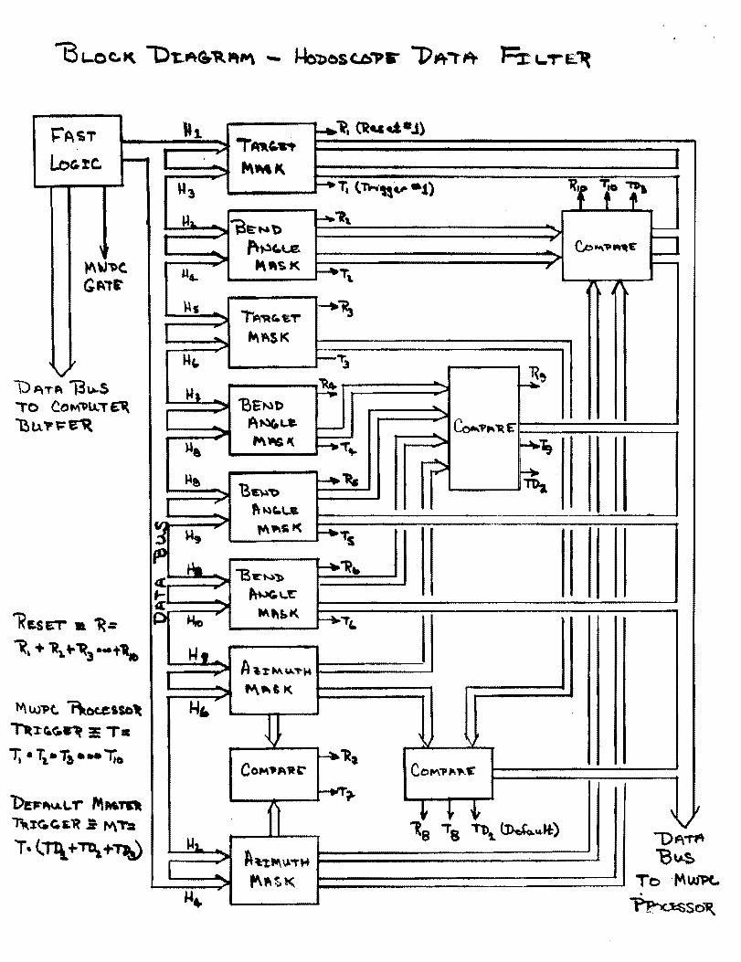
A. HodoscopeFilter (Trigger Level II)
During the proportional chamber gating time the
latched hodoscope data will be filtered to select
master trigger candidates. The block diagram outlines
the tests to which the hodoscope data is subjected.
Each mask is a matrix of two sets of hodoscope elements
hardwire programmed to fulfill certain coincidence
requirements. The hodoscope pairs are examined to
allow only acceptable trajectories through the magnets,
collimators, etc. In addition, the hodoscope analysis
includes a check on the azimuthal correlation of the
-30
track candidates in the forward and recoil spectrometers.
Filtered hodoscope data outputs of the masks contain
only acceptable hits on each hodoscope plane. Each
mask also generates a trigger (reset) signal if the
coincidence requirements are (not) met.
The individual masks are technically straight
forward to make and require - 3 logic levels. The
overall decision time is therefore < 100 ns using
emitter-coupled fast logic.
Immediately following the parallel masking,
comparison of the fi1~ered hodoscope data is performed to
eliminate data which has not·satisfied all masks in
which the individual hodoscopes participate. This
comparison requires at most 2 logic levels or roughly
50 ns. At this stage ambiguous events are defined as
those in which more than one element of H2 , H4 , H6 ,
HS' Hg or H10 satisfies all masks. Ambigous events
will result in a master trigger and computer interrupt.
For unambigous events satisfying all masks the
filtered hodoscope data and a Level II trigger will
be communicated "to th~ proportional chamber processor.
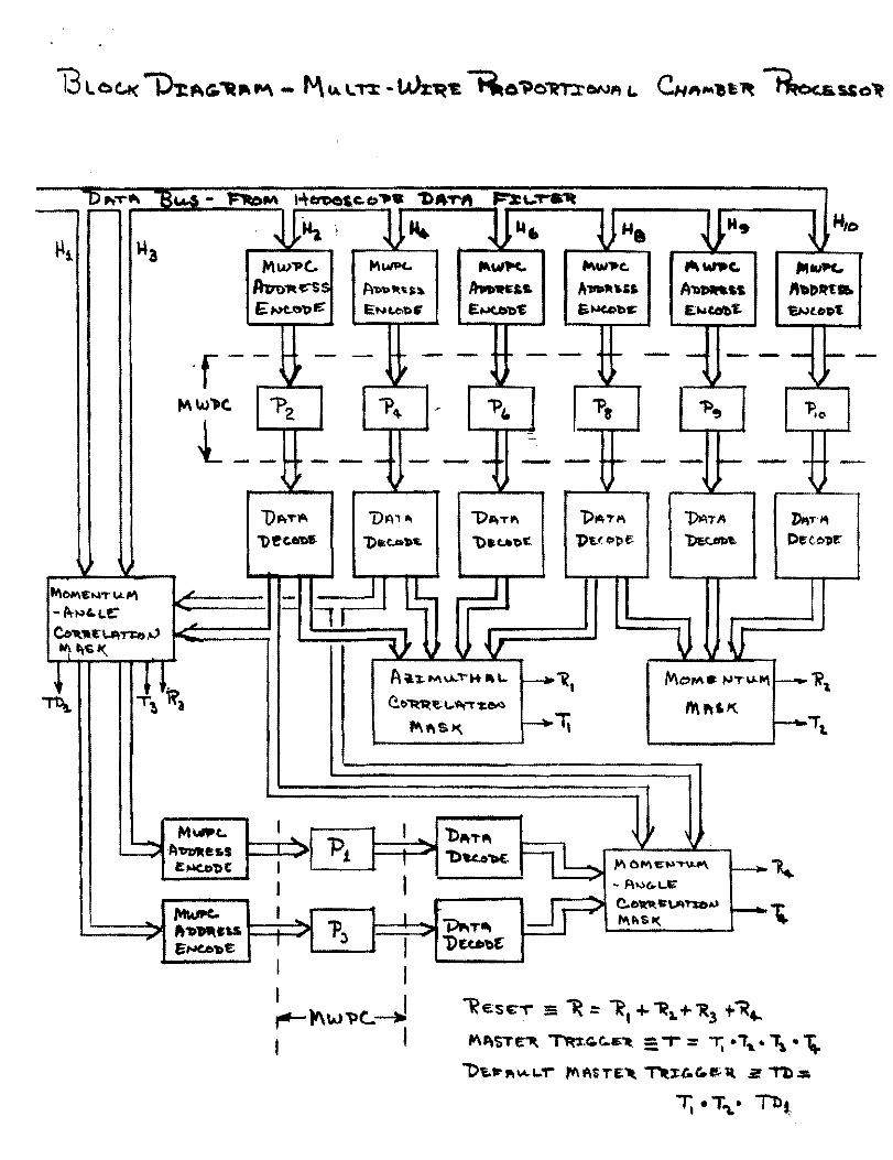
B•. Multi-Wire Proportional Chamber Processor (Level III)
The definition of single track candidates in the
hodoscope filter simplifies propo~tiona1 chamber
processing and results in a significant saving in
processing time. The chamber information is processed

-31
primarily in order to improve the resolution on the
trigger candidates and to check for recoil production
angle and recoil momentum correlation. The block
diagram outlines the essential features of the processor.
A trigger from the hodoscope filter initiates
addressing and subsequent readout of the hodoscope
defined regions of interest in MWPC planes P 2 , P 4 ,
P6 , PS' P9 and PlO • The chamber data is decoded to
the forward and recoil spectro~eter bend angles
(momenta) and azimuths. These are parallel masked to
insure
i) that the momenta are in the
range of interest and
ii) that the tracks are azimuthally
correlated.
In ?arallel with these masks, the recoil bend angle
(me-mentum) is matrixed with the recoil production
an~rle candidates. This preprogrammed hare.wire matrix
wi pass only i:.hose HI H3 combinations cc;'~'r.esponding
to a production angle which is consist.(~nt I,dth the
k.:.U:.!Ulatic5. If more than one HI H3 pair. sc.tisfies
1:1H; mask, a default master trigger will. re,!:;ult. :p.
sj,l!':-jle H1. H3 paL: \'.'111 initiate readou·t', of the co:crespone
ill'j '!:-' 1 P 3 regions. The production ang~~e w5.11 be de
c0(,~,d and again masked with the recoil momentum.

-32
The output of the processor will be a) a system
reset if any mask fails or b) a master trigger and
computer interrupt if all masks are satisfied or c) a
default master trigger if more than one Hl H3 pair is
found to agree with the calculated momentum (assuming
the azimuth and forward hend angle masks are satisfied)
or if any addressed chamber region contains more than
one wire "hit". The complete processing of an event
will require severnl VS.
The hodoscopo filter and processing system described
here will, as detai!ed in Section VI, result in a
master trigger r·3.te. of - .l/hr for randoms and non
target associated event.s. This is an improvement by a
factor of - 500 ft·,)·n tLe hodoscope coincidence rate in
lev·:!! 1 of the t:~~~. ~>:l':-;:. In the worst case if the
hc.,,:'I.n'<;cl)pn single:1 r"3.t-l?~; p'Juld increase by a factor of
2{l ,-"')ver th:! calc'llCitt:z.d inclusive rate, the master
tri;:;ger rata. for. ,-:.0.00 so-.;trces would increase to - 20/hour.
Most of the3e '.V':::':ld J:(;;ult from the default conditions
in the hodoscope ::: 1 to::. Even in this case the elastic
and quasi-elastic master triggers will dominate by a
factor of 10 at ·thE! largest It'l configuration.
~M""D"T~ "B.....a- '-+en>o,c.()"'. 1)A,...,. ~,....r.1It H,o
ro-
~ ~~. IN. ~ .., ~ ~ W1 ~ ~, ~
~l "'a ~
Mw"'Pc... ~wP(" MWltc., "..".c.~~ "'1U1I'C..1hn>'R t:'"$ S ~l>t>lit,t.~ 1hwK".. A..-~" A'tI~ss '''.r>rtt:. E~o~.r Ii::N t.l:>1). £~~ &.~be' £Ntob't. 1Wt.ODt:
'f- ,... - - r - - r - - - --i -- -J' ~ , ~ ,
\II 'oj
~w')c. "P~ "'Pq. .~ "'Pc. 1>. ~~ 'P,o ..t - ""~- -- - - - - -. - -I -,
" l)~T" 1>~C.O-
\oj v foI\OI'l\e;",,.. ~ 111\ .J' - -- f:tr~"Le: I I c..''''t:~T1:o ,., -'.. ~ l\c,1(
J. Jll~l
MW'Pt.. I ~
... "Pt'A~alos ;a ..... £...c.ol)t I
I ~(.. I... ... ""D~eu. 1:) e....ee'D~
I
'J oJ V
UA'" "'D~,..... "PAT... 1)ATI4 iMT~
1)a:eP".. '1)_t..1>':: 1>~f.;bbe: ~ C>ec.o'Pr
I~ ~
" V l\ \I i A~tN\u.."'''''_\'' i"""'i, MOM. ,..,,..u..-., r--1? c.f>1lt.~~ ........,. "U/f') ff\ ,,&K
~1\$K. ~1i f---t-ia.
I '" .iIJ
I, I
I
bAT-III ' II \ 11
n~"Dk6~ "'" 0."" e;~~ t----~ - At..>t..t..~
~ --. C-blt"fl"\ATI:OjI,) ~~
~T~ "" t:\ 'S I(
"Du.'f)t
~e.s~T' :5 'It .::: '"R, +- ~a.+"R3 +~4-~J\ST~ ~G.G.6'1t, =. "T"::: -r; .i,."\ • ~
1)1.It' PI \,4.I.:r ff\ f\S T E: "Il i"Itl:(''' p; 1t 3! "'f1).:=.
T. •T'\,. Tb"
l="ACST
LoG-%c, I-
\
)4\ \J"D(,
G~"I'
it V
"1
"3 "2
I , '"'4
", ...
1-4"
Wl _
;:II
"e. ~e.
Ij ~9
IfIJ t-4a 4. , ,.... «: ~
IP u.o
1-1,-I
f.I".
~1
... :::II.
fo'..
~~. (t-....:I..J),..-,.... ~MK
~,. (-n...·U.,. -1) 1ft to f' 1k-....b
I-'-"It. I--
"'~t.U!. .. Co"",,,,,,,,11: tJ
~~f.1( I-~,.... ,
/'
"'~t.t" --.~
~~K
-"3 . 1<"
~ ~.
"BEND ... A~t.e. - ~",,11(E'
"'''''' 4,... ::J. ~i,
? ~.
"B~"O ~ ... -ro,.
"~c..,-- ---Jl\f\st<
;JJ~..'"'B~~'])
~\..t:
W\'-L-t( ~T"
A"%:M~""H ~~'I(
l ,
CC"''''''1tC'' ~'R~
Co......,,,"'"'£' ~?-
~ 1 J ~ ~ 'v II
18 18 "tb~ ~~U:) ""'011\ ~:t:'t""v..,.... l3u.So
"'" s t( To 'M.
PaT" 13~s COt-'\1>ll,,. ~
U?f:~ o
E.SET • ~=
,+ 'Rl. ..~ ...t" W'Pc.. 1\~,so~
~G..(i.":: T
• T1.- Ta··-T,o
l.>uII\U.""" ,.,MTCIt T",rGr('S".'R .= ~'T:a T•(:TIl+~+TJa)

-33
FIGURE CAPTIONS
Figure 1. Energy dependence of the pp elastic
differential cross section at several
fixed values of Itl.
Figure 2. Energy dependence of the pp elastic
differential cross section in the region
of the secondary maximum {It I ~ 2 (GeV/c)2)
in the ISR energy region. A significant
increase in the crqss section at IS ~ 30 is
oberved. The solid curve shows the s-depend
ence predicted by the Impact Picture.
Figure 3. Small Itl K+P elastic differential cross
section as measured by Meyer et a1. in
(Fermilab Experiment 7). The curves are
the predictions of the Impact Picture (Ref.
S). Some ISR pp elastic data is also shown.
Figure 4. Impact Picture predictions for the pomeron
contribution to the ~p and kp elastic
cross section at 200 GeV/c. These are
then the predicted minimum cross sections
that will be encountered at 200 GeV/c.
Figure S. Recoil proton laboratory angle vs. It I for
~p elastic scattering. This curve is
virtually energy independent (E > 50 GeV)
and has little dependence on the type of
forward scattered particle (k, p). Figure 6. Laboratory angle of the forward scattered
.._-_._--------

-34
pion in ~p elastic scattering at several
fixed values of incident momentum.
Figure 7. Apparatus arrangement for the proposed
experiment in the 200 GeV/c configuration.
Figure 8. Recoil spectrometer layout. The plan view
in the upper left shows the 2 magnet poles,
the 16" target and the beam line passing
through the slot in the pole. Also shown
are the approximate locations of the recoil
arm detectors (hodoscopes and MWPC). The
elevation view in the lower left shows the
ray trace of 6 GeV/c particles at azimuths
of ± 150 • The cross section of the magnet
in the upper right shows the slot allowing close
approach to the beam.
Figure 9. Calculated It I acceptance of the recoil
spectrometer at the 3 settings required to
cover the region 2 ~ It I ~ 12.7 (GeV/c)2.
The It I resolution of the spectrometer is
such that the geometric acceptance does not
change by more than - 4% within the resolu
tion.
Figure 10.Layout of the forward spectrometer showing
the target to the left, the sweeping magnet,
momentum analyzing magnet, Cerenkov counters
and the approximate detector locations. Below
the two magnets are shown expanded cross

-35
sectional views. The beam passes through the aperture
of the sweeping magnet and a slot in the pole of the
(vertical bend) analyzing magnet is provided for the
beam pipe.

-36
REFERENCES
lD. C. Carey, J. R. Johnson, R. Kammerud, M. Peters,
D. J. Ritchie, A. Roberts, J. R. Sauer, R. Shafer,
D. Theriot, J. K. Walker, and F. E. Taylor, Phys.
Rev. Letters 33, 327, Phys. Rev. Letters 33, 330.
2 D• Horn and F. Zacharism, Hadron Physics at Very
High Energies, W. A. Benjamin Inc., Reading, Mass.
(1973) and references cited therein.
'Results presented at the London Conference, July,
1974 by the Aachen-CERN-Geneva-Heidelberg-Turrin
collaboration.
~H. Cheng, J. K. Walker, T. T. Wu, Paper presented
to the XVI International Conference on High Energy
Physics, Batavia (1972).
sT. T. Wu, Invited talk at the Fifth International
Conference on High Energy Collisions, Stony Brook,
N. Y., August, 1973.

Q8
1.2 2.0 3.0
Figure 1
• CHOV o ACHGT • FNAL0.15 POWER LAW
S-n REGION WHERE O"'T GROWS
0.1 ~REGION OFI \ IAPPROX. : \ :SCALI NG :f \ I I
005 \~ III
I ---
20 40 60
Js[GeV]
Figure 2
PRELIMINARY )( 200GeV/c • 100 GeV/c - PREDICTION OF.
IMPACT PICTURE
+ +K p .... K P
"'.c , E ,
bl .....1 '"0 '"0
pp-pp
.01 PRELIMINARY (PRESENTED AT LONDON CONF. ) ISR DATA
.001 + 300 GeV/c
.0001 '--....t-----'_....a...-----'i.-..........---..I~.....
. 0 .2 A .6 .8 1.0 1.2 1.4
-t (GeV/c)2
Figure 3

-~ s-b
N '" ~ ..:J
-litD
-H10
Figure 4

-----
'.
~
~ ~
~
--. \/I
~ tJ Q.. ~
~
k ~
~
ru .~
~
to... Cb-i
~
rJ
(Y'l
Ln
Q)
J..I ::s ~
..... <
)
n"'"
.. ()-o
\y.:\o
0
'-. ~
'::'~
- o
(1)
1'"
l:>
Q;
~.
"b
c.r: .., 'b ?>
". "" \.......
? ~
~
~
-:". ....
~
~ ~
:-- ~
~
t:rj
~
1-'
IJ.'l ~
11
::--CD
~
0'1

"
FORWARD "'.,_ J
SWEEPING ~.-~SPECTROMFJrER CALORIMETERMAGNET ! MAGNET J
Figure 7 fl

:Z:::~.'-
I ....
;
I I
,/ /
/ /t
I I
I II1/
II
!: I I
IiI
I
/ 1
"-../
i
7
i I i i
\ I
\ \ \ \ I
\ \
f I
~ i
1-3 !
I, I~ I I
I. ,
\ "'-..._
-'''"
,,"---
-_
/----~
.. =.=
/
, I j
-,
a- \oS)
-(Xl
N
r-.. ~
:>
$ Q1
"iJ
oo
• ..
N 4
c -
{;'
f.----t
fSj 'J PLAN VIEW f,t H's,'J o ,'.... '" ?E-:~::"-J~' ~. - -f:.~-.'." A,c. - ~ ;:.,-,,:::~,,: ::::~..::,-g;§l'f,~~:,< ' " ,--'"._-r
( ! FORWARD
SPEC'I'ROME'l'ER
1
b'RONT VIEW, FRON'l' VIEW, Sw'EEPJNG JVTAGNE'11 I'
MAGNET~ l'
Figure 10