Embed Size (px)
Citation preview
24 Oilfield Review
Scientific Deep-Ocean Drilling: Revealing the Earth’s Secrets
Tim BrewerUniversity of LeicesterLeicester, England
Tatsuki EndoMasahiro KamataFuchinobe, Japan
Paul Jeffrey FoxTexas A&M UniversityCollege Station, Texas, USA
Dave GoldbergGreg MyersLamont-Doherty Earth ObservatoryPalisades, New York, USA
Yoshi KawamuraShin’ichi KuramotoJapan Agency for Marine-EarthScience and Technology Yokosuka, Japan
Steve KittredgeWebster, Texas
Stefan MrozewskiHouston, Texas
Frank R. RackJoint Oceanographic Institutions, Inc.Washington, DC, USA
adnVISION (Azimuthal Density Neutron tool), AIT (ArrayInduction Imager Tool), APS (Accelerator Porosity Sonde),DSI (Dipole Shear Sonic Imager), Formation MicroScanner,GeoFrame, geoVISION, GPIT (General Purpose InclinometryTool), HLDT (Hostile Litho-Density Tool), proVISION, RAB (Resistivity-at-the-Bit), SFL (Spherically Focused Resistivity), SlimXtreme, VSI (Versatile Seismic Imager) and WST (Well Seismic Tool) are marks of Schlumberger.For help in preparation of this article, thanks to John Beckand Ann Yeager, Texas A&M University, College Station,Texas, USA; Rosalind Coggon, Southampton OceanographyCentre, England; Javier Espinosa and Nathan Frisbee,
Webster, Texas; Agus Hadijanto, Tokyo, Japan; MartinJakobsson, Stockholm University, Sweden; Robert Kleinbergand Lisa Stewart, Ridgefield, Connecticut, USA; Herbert Leyton, Belle Chasse, Louisiana, USA; Dave McInroy, British Geological Survey, Edinburgh, Scotland; and Kerry Swain, NASA, Houston, Texas.Thanks also to the Integrated Ocean Drilling Program, andto Joint Oceanographic Institutions (JOI), Washington, DC,USA; Lamont-Doherty Earth Observatory, Palisades, NewYork, USA; and Texas A&M University, College Station, USA,for providing the Ocean Drilling Program material used inthe preparation of this article.
The oceans and their underlying sediments and rocks act as natural laboratories that
record the Earth’s dynamic processes from past to present. Scientific deep-ocean
drilling, sampling and borehole measurements collected during the past 40 years are
enhancing our knowledge of the Earth, giving clues to the distribution of mineral
resources, to global climate change and to potential natural disasters. While some
technologies used in the oil and gas industry are deployed for scientific research,
other methods and tools developed specifically for deep-ocean drilling are also
finding applications in the energy industry.
Understanding the past is critical to predictingthe future. The ocean floors and their underlyingsediments and rocks contain a high-resolutionrecord of both the Earth’s history and its currentconditions. Information locked within thesestrata has the potential to answer fundamentalscientific questions. Scientific ocean-drillingprograms provide keys to unlock this buriedtreasure trove of data, which leads to a betterunderstanding of climatic changes, natural haz-ards such as earthquakes, volcanic eruptionsand floods, and mineral and energy resources.Technologies commonly used in the oil and gasindustry for drilling, borehole measurementsand sampling play a major role in scientificocean drilling.
Seafloor drilling during the past 40 years hasled to exciting scientific discoveries. For exam-ple, in 1968, drilling confirmed that sedimentsand rocks flooring the south Atlantic becameincreasingly older with distance from the axis ofthe mid-Atlantic oceanic ridge, thereby verifyingthe plate tectonics hypothesis.1
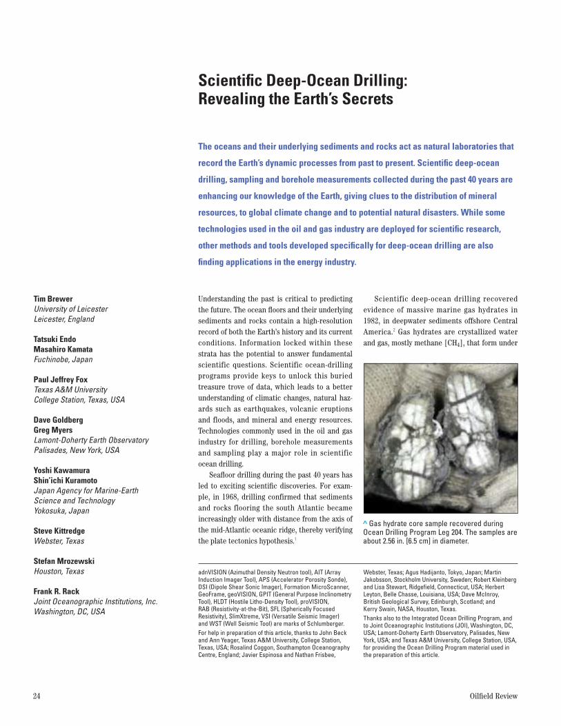
Scientific deep-ocean drilling recovered evidence of massive marine gas hydrates in1982, in deepwater sediments offshore CentralAmerica.2 Gas hydrates are crystallized waterand gas, mostly methane [CH4], that form under
> Gas hydrate core sample recovered duringOcean Drilling Program Leg 204. The samples areabout 2.56 in. [6.5 cm] in diameter.
Winter 2004/2005 25
1. Le Pichon X: “Sea-Floor Spreading and Continental Drift,”Journal of Geophysical Research 73, no. 12 (June 1968):3661–3697.
2. Kvenvolden KA and McDonald TJ: “Gas Hydrates of theMiddle America Trench, Deep Sea Drilling Project Leg 84,”in Von Huene R, Aubouin J, Arnott RJ, Baltuck M, Bourgois J, Filewicz M, Helm R, Lienert B, McDonald TJ,McDougall K, Ogawa Y, Taylor E and Winsborough B: Initial Reports of the Deep Sea Drilling Project 84.Washington, DC: US Government Printing Office (1985):667–682.
3. Kleinberg LR and Brewer PG: “Probing Gas HydratesDeposits,” American Scientist 89, no. 3 (May-June 2001):244–251.
4. Collett T, Lewis R and Uchida T: “Growing Interest in GasHydrates,” Oilfield Review 12, no. 2 (Summer 2000): 42–57.
5. Kerr RA: “Signs of a Warm, Ice-Free Arctic,” Science 305,no. 5691 (September 2004): 1693.
6. Schlumberger logs were acquired since the beginning of scientific deep-ocean drilling with Project Mohole (reference 10). Schlumberger has also been involved inonshore scientific drilling programs, leading to new technology for the oil and gas industry, for example, anew drilling technology that combined rotary drilling andsandline core retrieval techniques. For more on continentalscientific drilling: Bram K, Draxler J, Hirschmann G, Zoth G,Hiron S and Kühr M: “The KTB Borehole—Germany’sSuperdeep Telescope into the Earth’s Crust,” OilfieldReview 7, no. 1 (January 1995): 4–22.
7. IODP is a global partnership of scientists, research institutions and government agencies. The US NationalScience Foundation (NSF) and Japan’s Ministry of Education, Culture, Sports, Science and Technology(MEXT) are lead members who make equal financial contributions. The balance of the funding is provided bythe contributing member European Consortium for OceanResearch Drilling (ECORD), and the Ministry of Scienceand Technology (MOST), China, an associate member.
conditions of high pressure and low tempera-tures (previous page).3 Hydrates have steadilygained recognition in the oil and gas industrybecause they are both a drilling hazard and apotential energy resource for the future.4
More recently, in 2004, drilling in the ice-covered Arctic Ocean at the crest of theLomonosov Ridge has provided preliminary evidence that the Arctic was ice-free and warmabout 56 million years ago.5 Scientists analyzingthe cores and log data hope to determine when,why and how the Arctic climate changed fromhot to cold, and to gain insight on current globalwarming trends. Scientists are also speculatingabout the possibility of oil and gas prospects inthe Arctic Ocean.
Important facilitators to these discoverieshave been advances in drilling, coring and logging technology. Borehole measurements,routinely collected in oil and gas wells, also playa major role in scientific ocean research by providing data in sections with poor or no corerecovery, and in linking core measurements withlarger scale seismic data. Schlumberger hasbeen involved in scientific deep-ocean drillingprograms since 1961, providing borehole measurements and working closely with scientists to develop technology to support theirscientific objectives.6
While many tools and techniques developedfor oilfield use are being applied in scientificresearch, technologies that advanced under sci-entific drilling programs are also useful in drillingfor oil and gas, particularly deepwater drillingand in logging-while-drilling (LWD) applications.
In this article, we first review the historicalcontext for scientific deep-ocean drilling andthen examine current and emerging technolo-gies, particularly for downhole measurements,that are essential to achieving the goals of scientific drilling. Finally, we describe the newIntegrated Ocean Drilling Program (IODP),which will offer flexibility in its use of diversedrilling capabilities in all ocean basins regard-less of water depth and geographic location.7
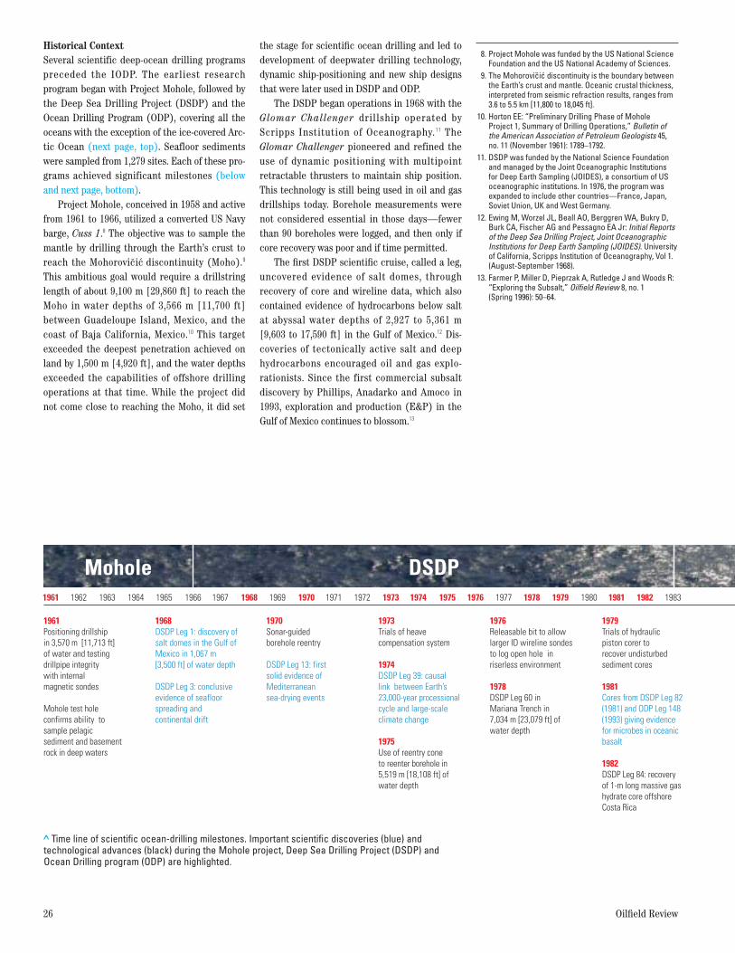
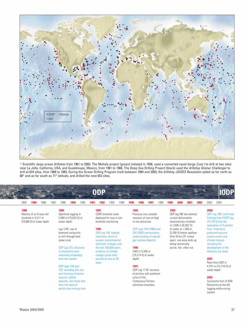
Historical ContextSeveral scientific deep-ocean drilling programspreceded the IODP. The earliest research program began with Project Mohole, followed bythe Deep Sea Drilling Project (DSDP) and theOcean Drilling Program (ODP), covering all theoceans with the exception of the ice-covered Arc-tic Ocean (next page, top). Seafloor sedimentswere sampled from 1,279 sites. Each of these pro-grams achieved significant milestones (belowand next page, bottom).
Project Mohole, conceived in 1958 and activefrom 1961 to 1966, utilized a converted US Navybarge, Cuss 1.8 The objective was to sample themantle by drilling through the Earth’s crust toreach the Mohorovicic discontinuity (Moho).9
This ambitious goal would require a drillstringlength of about 9,100 m [29,860 ft] to reach theMoho in water depths of 3,566 m [11,700 ft]between Guadeloupe Island, Mexico, and thecoast of Baja California, Mexico.10 This targetexceeded the deepest penetration achieved onland by 1,500 m [4,920 ft], and the water depthsexceeded the capabilities of offshore drillingoperations at that time. While the project didnot come close to reaching the Moho, it did set
the stage for scientific ocean drilling and led todevelopment of deepwater drilling technology,dynamic ship-positioning and new ship designsthat were later used in DSDP and ODP.
The DSDP began operations in 1968 with theGlomar Challenger drillship operated byScripps Institution of Oceanography.11 TheGlomar Challenger pioneered and refined theuse of dynamic positioning with multipointretractable thrusters to maintain ship position.This technology is still being used in oil and gasdrillships today. Borehole measurements werenot considered essential in those days—fewerthan 90 boreholes were logged, and then only ifcore recovery was poor and if time permitted.
The first DSDP scientific cruise, called a leg,uncovered evidence of salt domes, throughrecovery of core and wireline data, which alsocontained evidence of hydrocarbons below saltat abyssal water depths of 2,927 to 5,361 m[9,603 to 17,590 ft] in the Gulf of Mexico.12 Dis-coveries of tectonically active salt and deephydrocarbons encouraged oil and gas explo-rationists. Since the first commercial subsaltdiscovery by Phillips, Anadarko and Amoco in1993, exploration and production (E&P) in theGulf of Mexico continues to blossom.13
26 Oilfield Review
8. Project Mohole was funded by the US National ScienceFoundation and the US National Academy of Sciences.
9. The Mohorovicic discontinuity is the boundary betweenthe Earth’s crust and mantle. Oceanic crustal thickness,interpreted from seismic refraction results, ranges from3.6 to 5.5 km [11,800 to 18,045 ft].
10. Horton EE: “Preliminary Drilling Phase of Mohole Project 1, Summary of Drilling Operations,” Bulletin of the American Association of Petroleum Geologists 45,no. 11 (November 1961): 1789–1792.
11. DSDP was funded by the National Science Foundationand managed by the Joint Oceanographic Institutions for Deep Earth Sampling (JOIDES), a consortium of USoceanographic institutions. In 1976, the program wasexpanded to include other countries—France, Japan,Soviet Union, UK and West Germany.
12. Ewing M, Worzel JL, Beall AO, Berggren WA, Bukry D,Burk CA, Fischer AG and Pessagno EA Jr: Initial Reportsof the Deep Sea Drilling Project, Joint OceanographicInstitutions for Deep Earth Sampling (JOIDES). Universityof California, Scripps Institution of Oceanography, Vol 1.(August-September 1968).
13. Farmer P, Miller D, Pieprzak A, Rutledge J and Woods R:“Exploring the Subsalt,” Oilfield Review 8, no. 1 (Spring 1996): 50–64.
1961 1962 1963 1964 1965 1966 1967 1968 1969 1970 1971 1972 1973 1974 1975 1976 1977 1978 1979 1980 1981 1982 1983
DSDPMohole
1968DSDP Leg 1: discovery of salt domes in the Gulf of Mexico in 1,067 m [3,500 ft] of water depth
DSDP Leg 3: conclusive evidence of seafloor spreading and continental drift
1970Sonar-guided borehole reentry
DSDP Leg 13: first solid evidence of Mediterraneansea-drying events
1973Trials of heave compensation system
1974DSDP Leg 39: causal link between Earth’s 23,000-year processional cycle and large-scale climate change
1975Use of reentry cone to reenter borehole in 5,519 m [18,108 ft] of water depth
1979Trials of hydraulic piston corer to recover undisturbed sediment cores
1981Cores from DSDP Leg 82 (1981) and ODP Leg 148 (1993) giving evidence for microbes in oceanic basalt
1982DSDP Leg 84: recovery of 1-m long massive gas hydrate core offshore Costa Rica
1976Releasable bit to allow larger ID wireline sondes to log open hole in riserless environment
1978DSDP Leg 60 in Mariana Trench in 7,034 m [23,079 ft] of water depth
1961Positioning drillship in 3,570 m [11,713 ft] of water and testing drillpipe integrity with internal magnetic sondes
Mohole test hole confirms ability to sample pelagic sediment and basement rock in deep waters
> Time line of scientific ocean-drilling milestones. Important scientific discoveries (blue) andtechnological advances (black) during the Mohole project, Deep Sea Drilling Project (DSDP) andOcean Drilling program (ODP) are highlighted.
Winter 2004/2005 27
> Scientific deep-ocean drillsites from 1961 to 2003. The Mohole project (green) initiated in 1958, used a converted naval barge Cuss I to drill at two sitesnear La Jolla, California, USA, and Guadeloupe, Mexico, from 1961 to 1966. The Deep Sea Drilling Project (black) used the drillship Glomar Challenger todrill at 624 sites, from 1968 to 1983. During the Ocean Drilling Program (red) between 1984 and 2003, the drillship JOIDES Resolution sailed as far north as80° and as far south as 71° latitude, and drilled the next 653 sites.
DSDPODP
Mohole
1984 1985 1986 1987 1988 1989 1990 1991 1992 1993 1994 1995 1996 1997 1998 1999 2000 2001 2002 2003 2004
ODP
1985Reentry of an 8-year-old borehole in 5,511 m [18,080 ft] of water depth
1989Openhole logging in 5,980 m [19,620 ft] of water depth
Leg 124E: use of diamond coring bits to drill through hard ocean crust
ODP Leg 125: discovery of serpentine mud volcanoes emanating from the mantle
ODP Legs 158 and 193: revealing the size and structure of active massive sulfide deposits, like those that form the basis of world-class mining sites
1991CORK borehole seals deployed for true in-situ borehole monitoring
1992ODP Leg 146: highest resolution record of oceanic environmental and biotic changes over the last 160,000 years; evidence of climate change cycles with periods as low as 50 years
1999ODP Leg 186: two seismic/ crustal deformation observatories installed in 2,000 m [6,562 ft] of water at 1,000 m [3,280 ft] below seafloor. Only 50 km [31 miles] apart, one area ends up being seismically active, the other not
1995Pressure core sampler recovery of core at high in-situ pressures
ODP Legs 164 (1995) and 204 (2002) revolutionize understanding of natural gas hydrate deposits
1996LWD in 5,056 m [19,214 ft] of water depth
1997ODP Leg 171B: recovery of pristine soft-sediment cores of the Cretaceous/Tertiary extinction boundary
2000ODP Leg 189: confirmed findings from DSDP Leg 29 (1973) that the separation of Australia from Antarctica produced massive ocean current and climate change– including the development of the Antarctic ice sheet
2001Real-time LWD in 4,791 m [15,718 ft] of water depth
2002Successful test of RAB Resistivity-at-the-Bitlogging-while-coringsystem
IODP

Geophysicslaboratory
Moon pool
Downhole measurements and auxiliary laboratories
Core, physical properties and paleomagnetism laboratories
Microbiology, paleontology and chemistry laboratories
Computer laboratory and lounge
Photography laboratory
Shipboard Laboratories
28 Oilfield Review
< Drillship JOIDES Resolution with seven floorsof on-board laboratories. The 143-m [466-ft]drillship features a seven-story laboratorycomplex to analyze the wide variety of coresand logs collected worldwide. The ship ispositioned over the drillsite by 12 computer-controlled thrusters that support the mainpropulsion system. Near the center of the shipis the moon pool, a 7-m [23-ft] opening in thebottom of the ship, through which the drillstringis lowered. The drillship is a virtual universitythat can house 50 scientists and techniciansand 65 crew members, with a stack of labora-tories on seven floors. The bottom two floors(not shown) have core-storage facilities. Atthe fantail of the ship, on the left, is a geo-physics laboratory, which contains equipmentthat gathers ship position, water depth andmagnetic information used in studying theseafloor topography.
> A Schlumberger engineer acquiring real-time LWD data in the downholemeasurements laboratory.
> An ODP scientist working on core descriptions. (Photographcourtesy of Texas A&M University.)

Winter 2004/2005 29
The ODP, the next phase of the scientificdeep-ocean drilling programs, used the JOIDESResolution drillship operated by Texas A&M University in College Station (previous page).14
The ODP drilled 1,700 boreholes in water depthsranging from 91 to 1,828 m [300 to 6,000 ft] withmore than 213,000 m [699,000 ft] of core recov-ery.15 With successful well-logging results, wirelineacquisition became an integral part of the ODP,with more than 56% of the boreholes logged.16
The past four decades of scientific oceandrilling have benefited from numerous technolog-ical advances in wireline logging, drilling andmeasurement technologies, coring and samplingtechniques and long-term borehole-monitoringdevices. The development of technologies toaddress challenges in scientific deep-oceandrilling was the result of close collaboration bythe scientific community and the service industry.
Challenges in Scientific Deep-Ocean DrillingThere are many challenges associated withdrilling in deepwater and ultradeepwater areas,where water depths exceed 183 m [600 ft] and1,524 m [5,000 ft], respectively. The scientificobjectives of the ocean-drilling programsrequired drilling in water depths far greaterthan those common in E&P operations. The pro-gram had to develop technology to drill withouta riser—a large-diameter pipe that connects thesubsea blowout preventer (BOP) stack to a float-ing surface rig—commonly used in offshore oiland gas drilling (right). When drilling with ariser, drilling fluid circulates down the pipe,through the bit, and returns back to the surfacealong with rock cuttings through the exterior ofthe drillpipe.
14. The Ocean Drilling Program was managed by JointOceanographic Institutions, Inc. (JOI)—a consortium of US oceanographic institutions. The operation andstaffing of the drillship and core retrieval from sitesaround the world were managed by Texas A&M University(TAMU). The Lamont-Doherty Earth Observatory (LDEO) atColumbia University, New York, USA, managed the loggingservices and site survey data bank. The funding for ODP was initially provided by the US National ScienceFoundation (NSF) and later expanded to include otherinternational partners including Australia, Belgium,Canada, China, Denmark, Finland, France, Germany, Iceland, Ireland, Italy, Japan, Korea, The Netherlands,Norway, Portugal, Spain, Sweden, Switzerland, Taiwanand UK.
15. ODP core repositories are located at Lamont-DohertyEarth Observatory, Palisades, New York, USA; ScrippsInstitution of Oceanography, California; Texas A&M University; and Bremen University, Germany.
16. Goldberg D: “The Role of Downhole Measurements in Marine Geology and Geophysics,” Reviews of Geophysics 35, no. 3 (August 1997): 315–342.
> Riser drilling. The riser is a pipe that extends from the drilling platformdown to the seafloor. Drilling mud and cuttings from the borehole arereturned to the surface through the riser. The top of the riser is attached tothe drillship, while its bottom is secured at the seafloor. A blowout preventer(BOP) placed at the seafloor between the wellhead and the riser providesprotection against overpressured formations and sudden release of gas. Theriser pipe diameter of up to 21 in. [53.3 cm] is large enough to allow thedrillpipe, logging tools and multiple casing strings to pass through.
Drillpipe
Seafloor
Drilling fluid is pumpeddown through drillpipe.
Riser
Blowoutpreventer
Drilling fluid and cuttingsflow up between thedrillpipe and the riser.
Surface casing
LWD tool
Drilling fluid and cuttingsflow up between thedrillpipe and the boreholeor casing.
Second casing
Open hole

Without a riser, the drilling fluid spills out ofthe top of the borehole onto the seafloor, anddoes not return to the surface (above left). Thisdoes not create a problem for the seafloor environment, because seawater is used as thedrilling fluid. However, because no solids areadded, no mudcake forms. Without mudcake, the
borehole is less stable, which may lead to bore-hole collapse. Technology and solutions had tobe developed to deal with problems of shipheave, wellbore stability, reentry of wells inmore than 5,000-m [16,405-ft] water depth,along with other technical issues.
In conventional drilling for oil and gas, compensation devices treat the riser as the nonmoving reference to correct for depth uncertainties. A major improvement for loggingin riserless wells was the development of a large-displacement heave compensator to reducedepth uncertainties arising from ship heave. The
30 Oilfield Review
> Riserless drilling. Seawater is pumped down through the drillpipe to cleanand cool the bit. The drilling fluid and the cuttings flow up between thedrillpipe and the borehole or casing, where they spill onto the seafloor and donot return to the surface.
Cuttings flow into ocean.
Drillpipe
Cuttings
Seafloor
Seawater is pumpeddown through drillpipe.
Surface casing
Drill bit
Second casing
Open holeLWD tool
Seawater and cuttingsflow up between thedrillpipe and the boreholeor casing.
> The reentry cone. A large 3.7-m [12-ft]diameter, funnel-shaped installation on theseafloor serves as a conduit for relocating apreviously drilled hole and for landing andsupporting the surface casing string. The reentrycone is released through the moon pool (top).(Photograph courtesy of Texas A&M University.)
10 3⁄4-in. casing
16-in. casing
Seafloor
Mud skirt
Reentry cone
13 3⁄8-in. casing
20-in. casing

Winter 2004/2005 31
wireline heave compensator (WHC) system measures the vertical motion of the ship with anaccelerometer and automatically displaces thehydraulic piston and unspools logging cable bythe required amount.17 The WHC can adequatelycompensate for heaves of up to 6 m [20 ft]. Anew programmable rotary winch compensationsystem, developed by Schlumberger, is currentlybeing tested on the JOIDES Resolution.
With flexible drillpipe more than 5,000 mlong hanging in tension from the derrick, start-ing a borehole in bare rock is quite a challengewithout a riser. In hard-rock settings such as themid-oceanic ridges, spudding a hole and keepingit open becomes trickier due to the brittle, fractured nature of the rocks encountered. ODPdeveloped the hard-rock reentry system to spudholes in difficult environments using a hydraulichammer drill. The hammer drill is run inside thecasing, and it simultaneously drills a hole andadvances the casing.18 In the oil field today, technology using standard oilfield casing to drillthe well and then leave it in place to case thewell eliminates drillstring tripping and canincrease drilling efficiency by 20 to 30%.
Another challenge in riserless drilling wasreentry into preexisting boreholes. Reentry maybe required for several reasons, such as replacing a bit, or when returning to the bore-hole on multiple legs. To replace the bit, forexample, the drillstring must be raised, a newbit attached, and the string lowered back to thebottom into the same drill hole. The formidabletask of reentering a borehole on the ocean floorwas accomplished with the use of sonar scanning equipment and a reentry cone. Thereentry cone assembly comprises a reentry funnel mounted on a support plate that rests onthe seafloor and a housing to support multiplecasing strings (previous page, right). The reen-try system is wide at the top, above the seafloor,and narrows at the bottom near the base of theseafloor, thereby making it easy for the funnel toguide the drillpipe into the borehole.
The reentry cone allows a borehole to bereentered on multiple legs to deepen the hole orto install a borehole observatory for long-termdownhole measurement and sampling.
ODP developed two primary types of bore-hole observatories. Downhole broadbandseismometers with a bandwidth from 0.001 to10 Hz and strainmeters were deployed atselected sites, primarily in seismogenic, orearthquake-prone, zones near Japan and in theeastern Pacific Ocean. The other type of bore-hole observatory consists of instrumentation toobtain in-situ recordings of formation temperature
and pressure, and sampling of fluid geochemicalproperties. Similarly, permanent downholegauges to monitor flow rate, pressure and tem-perature are routine in the oil field for real-timeproduction optimization.19
However, effective utilization of boreholes ashydrogeological laboratories required sealingthem from the overlying ocean water, and allowing the formation to return to a state ofequilibrium. This was made possible by a circu-lation obviation retrofit kit (CORK) system, first deployed in 1991, which isolates boreholes from the ocean water above the seabed (above).
Temperature and pressure data recorded over aperiod of months to several years are recoveredusing manned or unmanned submersibles.
17. Lorsignol M, Armstrong A, Rasmussen MW andFarnieras L: “Heave Compensated Wireline LoggingWinch System and Method of Use,” US Patent no. 6,216,789 (April 17, 2001).
18. Shipboard Scientific Party, 2000: “Leg 191 PreliminaryReport: West Pacific ION Project/Hammer Drill Engineering,” ODP Preliminary Report 191, http://www-odp.tamu.edu/publications/prelim/191_prel/191PREL.PDF(accessed December 10, 2004).
19. Acock A, ORourke T, Shirmboh D, Alexander J, Andersen G,Kaneko T, Venkitaraman A, López-de-Cárdenas J, Nishi M,Numasawa M, Yoshioka K, Roy A, Wilson A and Twynam A: “Practical Approaches to Sand Management,”Oilfield Review 16, no. 1 (Spring 2004): 10–27.
> Circulation obviation retrofit kit (CORK). After coring and logging operations are completed, theborehole is isolated from the ocean water above by placing a CORK—a mechanical borehole sealretrofitted to a reentry cone (top). The seal prevents circulation of fluid into or out of the borehole.The CORK can be fitted with a sensor assembly that extends down into the borehole to measure in-situ temperature, pressure, and chemical and biological properties over several years. An advancedCORK incorporates multiple seals to enable recording of time-series observations in several isolatedzones (bottom). A submarine or an ROV (remotely operated vehicle) is deployed to download the dataperiodically. (Photograph courtesy of Texas A&M University.)
Mud skirt
Reentry cone
Datalogger forpressure recording
Hydraulic samplingports (from screens)
CORK head
Casing
Screens
Bridge plug
Packer inflation line
Packers
Hydraulic sampling lines(from screens)
A new generation of advanced CORKs willincorporate multiple packers to isolate subsurface zones in the borehole to measuretemperature, pressure, fluid chemistry andmicrobiology in each zone.
Although the water depths and borehole conditions are extreme, ODP and Schlumbergerhave engineered methods and tools for boreholemeasurements to satisfy scientific goals and tooperate effectively in hostile environments.
Advances in Borehole MeasurementsBorehole logging measurements are now consid-ered as vital to the scientific goals of scientificdeep-ocean drilling as they are to the E&Pindustry. They provide a continuous record offormation properties under in-situ conditions, alink between core data and larger scale regionalseismic data, and are sometimes the only usabledata when core recovery is poor or nonexistent.
The need for tools in slimhole, high-pressure,and high-temperature environments and the
need for high-resolution tools to characterizethin beds have been the driving forces behindthe customization and development of new borehole tools.
Sometimes logging sondes have to be conveyed through a pipe diameter as small as3.8 in. [9.7 cm] to make measurements in holesizes exceeding 11.8 in. [30 cm] in diameter. Toovercome this difficulty, some oilfield tools havebeen made slimmer. In 1988, the FormationMicroScanner device, with an outside diameter(OD) of more than 4.5 in. [11.4 cm], was modi-fied to 3.7-in. [9.4-cm] OD. Another tool, theslimhole WST Well Seismic Tool, was customizedby addition of two horizontal geophones. Thisenabled determination of shear-wave velocityand anisotropy of underlying rocks from a vertical seismic profile survey.
The goal of increasing vertical resolution ofdownhole measurements prompted scientists atLamont-Doherty Earth Observatory in Palisades,New York, USA (LDEO) to develop the multi-sensor gamma ray tool (MGT) in 2001. This toolincreases resolution by common-depth stackingand summing of the data received from an arrayof four gamma spectrometry sensors spaced 2 ft[61 cm] apart.20 The MGT increases the verticalresolution of natural gamma ray log data by afactor of three to four over conventional loggingtools, improving characterization of thin layersand their correlation with core data.
Typically, a wireline-conveyed system cannotlog the top interval just beneath the seafloorbecause the drillpipe has to be lowered about 50 to 100 m [164 to 328 ft] to ensure wellborestability. Additionally, long tool strings oftencannot log the bottom of the borehole. Also, incertain difficult environments, for example,alternating layers of hard and soft rock such aschert-chalk sequences, the rocks deteriorateafter drilling, resulting in both poor core recovery and poor logs. In such cases, LWD toolsare of critical importance and provide the onlyin-situ measurements.21
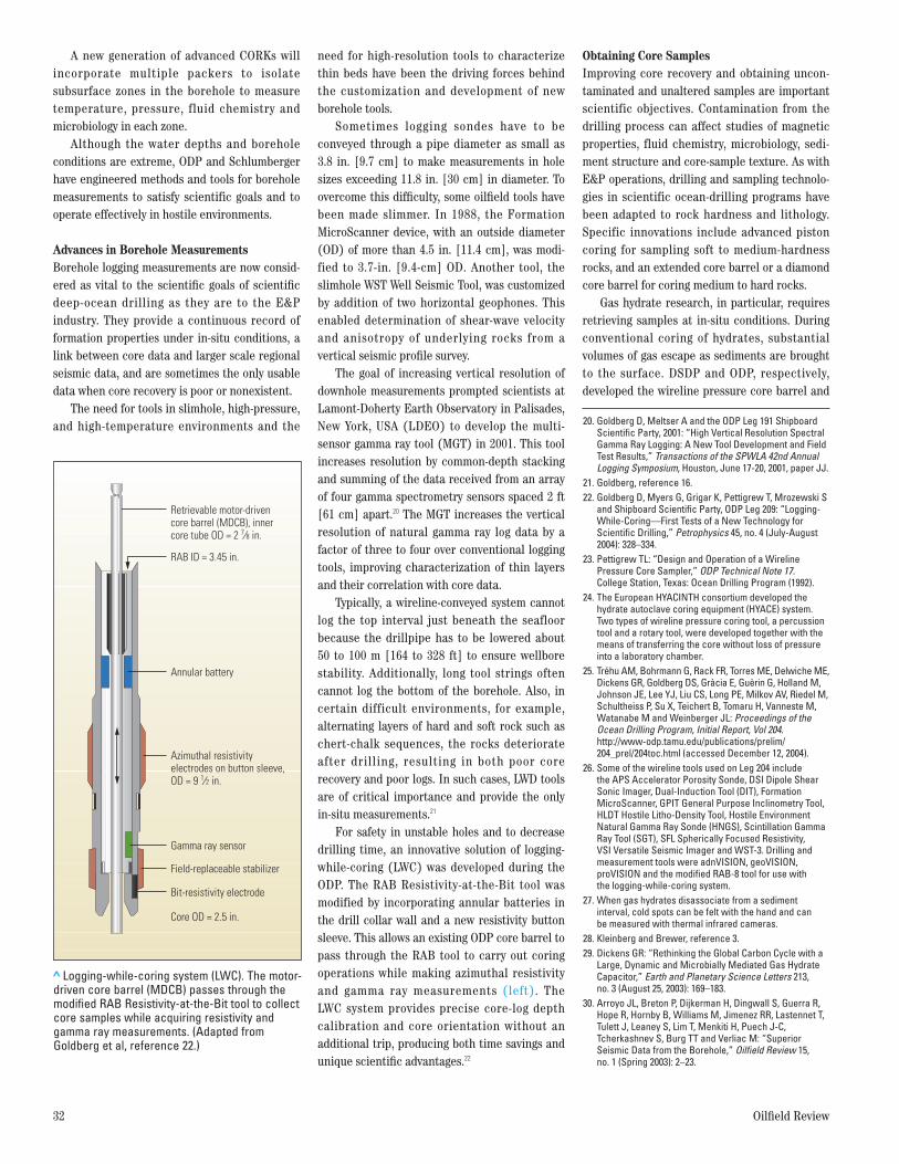
For safety in unstable holes and to decreasedrilling time, an innovative solution of logging-while-coring (LWC) was developed during theODP. The RAB Resistivity-at-the-Bit tool was modified by incorporating annular batteries inthe drill collar wall and a new resistivity buttonsleeve. This allows an existing ODP core barrel topass through the RAB tool to carry out coringoperations while making azimuthal resistivityand gamma ray measurements (left). The LWC system provides precise core-log depth calibration and core orientation without anadditional trip, producing both time savings andunique scientific advantages.22
Obtaining Core SamplesImproving core recovery and obtaining uncon-taminated and unaltered samples are importantscientific objectives. Contamination from thedrilling process can affect studies of magneticproperties, fluid chemistry, microbiology, sedi-ment structure and core-sample texture. As withE&P operations, drilling and sampling technolo-gies in scientific ocean-drilling programs havebeen adapted to rock hardness and lithology.Specific innovations include advanced pistoncoring for sampling soft to medium-hardnessrocks, and an extended core barrel or a diamondcore barrel for coring medium to hard rocks.
Gas hydrate research, in particular, requiresretrieving samples at in-situ conditions. Duringconventional coring of hydrates, substantial volumes of gas escape as sediments are broughtto the surface. DSDP and ODP, respectively,developed the wireline pressure core barrel and
32 Oilfield Review
20. Goldberg D, Meltser A and the ODP Leg 191 ShipboardScientific Party, 2001: “High Vertical Resolution SpectralGamma Ray Logging: A New Tool Development and FieldTest Results,” Transactions of the SPWLA 42nd AnnualLogging Symposium, Houston, June 17-20, 2001, paper JJ.
21. Goldberg, reference 16.22. Goldberg D, Myers G, Grigar K, Pettigrew T, Mrozewski S
and Shipboard Scientific Party, ODP Leg 209: “Logging-While-Coring—First Tests of a New Technology forScientific Drilling,” Petrophysics 45, no. 4 (July-August2004): 328–334.
23. Pettigrew TL: “Design and Operation of a Wireline Pressure Core Sampler,” ODP Technical Note 17.College Station, Texas: Ocean Drilling Program (1992).
24. The European HYACINTH consortium developed thehydrate autoclave coring equipment (HYACE) system.Two types of wireline pressure coring tool, a percussiontool and a rotary tool, were developed together with themeans of transferring the core without loss of pressureinto a laboratory chamber.
25. Tréhu AM, Bohrmann G, Rack FR, Torres ME, Delwiche ME,Dickens GR, Goldberg DS, Gràcia E, Guèrin G, Holland M,Johnson JE, Lee YJ, Liu CS, Long PE, Milkov AV, Riedel M,Schultheiss P, Su X, Teichert B, Tomaru H, Vanneste M,Watanabe M and Weinberger JL: Proceedings of theOcean Drilling Program, Initial Report, Vol 204.http://www-odp.tamu.edu/publications/prelim/204_prel/204toc.html (accessed December 12, 2004).
26. Some of the wireline tools used on Leg 204 include the APS Accelerator Porosity Sonde, DSI Dipole ShearSonic Imager, Dual-Induction Tool (DIT), FormationMicroScanner, GPIT General Purpose Inclinometry Tool,HLDT Hostile Litho-Density Tool, Hostile EnvironmentNatural Gamma Ray Sonde (HNGS), Scintillation GammaRay Tool (SGT), SFL Spherically Focused Resistivity, VSI Versatile Seismic Imager and WST-3. Drilling andmeasurement tools were adnVISION, geoVISION, proVISION and the modified RAB-8 tool for use with the logging-while-coring system.
27. When gas hydrates disassociate from a sediment interval, cold spots can be felt with the hand and can be measured with thermal infrared cameras.
28. Kleinberg and Brewer, reference 3.29. Dickens GR: “Rethinking the Global Carbon Cycle with a
Large, Dynamic and Microbially Mediated Gas HydrateCapacitor,” Earth and Planetary Science Letters 213,no. 3 (August 25, 2003): 169–183.
30. Arroyo JL, Breton P, Dijkerman H, Dingwall S, Guerra R,Hope R, Hornby B, Williams M, Jimenez RR, Lastennet T,Tulett J, Leaney S, Lim T, Menkiti H, Puech J-C,Tcherkashnev S, Burg TT and Verliac M: “Superior Seismic Data from the Borehole,” Oilfield Review 15,no. 1 (Spring 2003): 2–23.
> Logging-while-coring system (LWC). The motor-driven core barrel (MDCB) passes through themodified RAB Resistivity-at-the-Bit tool to collectcore samples while acquiring resistivity andgamma ray measurements. (Adapted fromGoldberg et al, reference 22.)
Retrievable motor-drivencore barrel (MDCB), innercore tube OD = 2 7⁄8 in.
Annular battery
RAB ID = 3.45 in.
Azimuthal resistivityelectrodes on button sleeve,OD = 9 1⁄2 in.
Field-replaceable stabilizer
Bit-resistivity electrode
Core OD = 2.5 in.
Gamma ray sensor

Winter 2004/2005 33
the pressure core sampler to recover samples atin-situ pressures up to 10,000 psi [70 MPa].23
These tools are particularly useful for samplinggas hydrates and for measuring the volume ofgas released from these samples. The need forpressurized sampling, which maintains the coreat downhole pressure in an autoclave chamber,inspired a European consortium to develop anew suite of tools known as the hydrate auto-clave coring equipment—the next generation ofpressurized coring systems.24
ODP Leg 204, conducted from July to August2002, provided the opportunity to test a widevariety of new technologies and measurementtechniques.25 The scientific objective of the mission was to understand the occurrence anddistribution of gas hydrates offshore Oregon,USA. It marked the first use of simultaneous logging and coring with the LWC system andextensive tests of pressurized coring tools. Leg204 also deployed a wide range of Schlumbergerwireline tools and logging-while-drilling (LWD)tools, and included tools developed by ODP tomeasure in-situ pressure.26 Digital infrared cameras were used for the first time in an ODPoperation to scan core samples. This is done assoon as they are retrieved from the gas hydrateinterval to record the temperature anomalies.27
Focus on Gas Hydrates Gas hydrates have been known to exist inmarine sediments since the early days of DSDP,but they were judiciously avoided in the pastbecause of drilling safety issues. However, agrowing interest in hydrates as a potentialresource for energy and in their possible influ-ence on climate change has made hydrates oneof the focus areas in scientific ocean drilling.
Hydrates found in deepwater sediments atouter continental margins are usually stable.Gas hydrates become unstable when ocean temperature rises or depressurization occursdue to a reduction in confining pressure, causedfor example by a decrease in sea level or a lossin sediment overburden.28 This triggers therelease of methane—a powerful greenhousegas—into the Earth’s oceans and atmosphere.Scientists have raised questions about theimpact of gas hydrates on the carbon cycle andon global climate.29 However, there is greatuncertainty about how much hydrate and freegas are actually contained in marine sediments.It is therefore important to know where and howhydrates accumulate, and to monitor conditionsthat could change their stability.
To reduce this uncertainty, 45 boreholeswere drilled at nine sites on the bathymetrichigh known as Hydrate Ridge, in about 790 m
[2,592 ft] of water, offshore Oregon, USA (top). Several geophysical measurements thatcan help quantify gas hydrates were performedduring Leg 204. These include nuclear magneticresonance, resistivity imaging, sonic logging andvertical seismic profiles (VSPs). Borehole seis-mic data were acquired with the VSI VerticalSeismic Imager tool, which can record simulta-
neously at multiple stations. With differentsource-receiver configurations, offset VSP andwalkaway VSPs were acquired to image the sub-surface away from the borehole.30
The three-dimensional (3D) seismic dataacquired over the nine drilled sites on the southern Hydrate Ridge provide a regional structural and stratigraphic setting (above). A
> ODP Leg 204 drillsites on Hydrate Ridge, offshore Oregon, USA. (Adapted from Tréhu et al, reference 25.)
1250
1249
1248
1247
1246
12451244
1252
1251
-800
44°33’ N125°09’W 125°06’ W 125°03’ W
44°36’ N
-900 -1,000
-1,100
-1,200
> East-west vertical slice through the three-dimensional seismic data. The seismic data show thestructural and stratigraphic setting of Hydrate Ridge at Sites 1244, 1245, 1246 and 1252. The high-amplitude reflector below the seafloor is the bottom-simulating reflector (BSR), and it corresponds tothe base of the gas hydrate stability zone. The BSR has a negative polarity, indicating high-velocitysediments containing gas hydrate that overlie low-velocity sediments containing free gas. Below theboundary AC, the seismic data are incoherent, and represent older, highly deformed sediments of theaccretionary complex at the core of Hydrate Ridge. Seismic reflections marked as A, B, B', Y and Y'are anomalously bright stratigraphic events. The depth scale in meters below seafloor (mbsf) is based on the assumption of a velocity of 1,550 m/s [5,085 ft/s] above 150 mbsf [492 ft] and 1,650 m/s[5,413 ft/s] below 150 mbsf. The reddish-orange lines indicate the depth of penetration at each site.(Adapted from Tréhu et al, reference 25.)
Dept
h, m
0
75
150
225
300
375
450
Two-
way
trav
eltim
e, s
1.1
1.2
1.3
1.4
1.5
1.6
1.7
1.8
1.9
4,100 ft1,250 m
BSR
BSR
AC
A
BY
Y B
Site 1245Site 1246
Site 1244
Site 1252
high-amplitude reflector referred to as the bottom-simulating reflector (BSR) results from astrong velocity contrast between the high-velocity sediments containing gas hydrates anddeeper low-velocity sediments containing freegas. This reflector is interpreted as the base ofthe gas hydrate stability zone. Seismic velocitiesfrom the VSPs clearly resolve this velocitydecrease, indicative of the presence of free gasbeneath the BSR that occurs 129 to 134 m [423 to440 ft] below the seafloor.
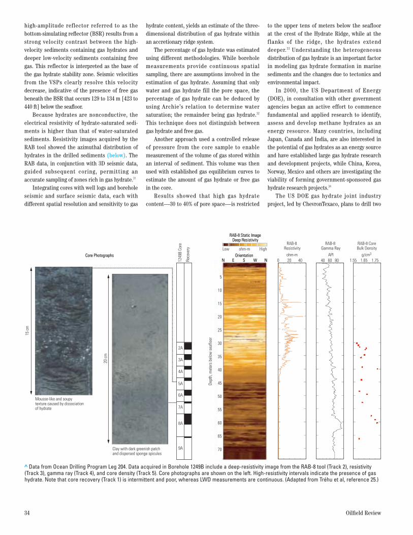
Because hydrates are nonconductive, theelectrical resistivity of hydrate-saturated sedi-ments is higher than that of water-saturatedsediments. Resistivity images acquired by theRAB tool showed the azimuthal distribution ofhydrates in the drilled sediments (below). TheRAB data, in conjunction with 3D seismic data,guided subsequent coring, permitting an accurate sampling of zones rich in gas hydrate.31
Integrating cores with well logs and boreholeseismic and surface seismic data, each with different spatial resolution and sensitivity to gas
hydrate content, yields an estimate of the three-dimensional distribution of gas hydrate withinan accretionary ridge system.
The percentage of gas hydrate was estimatedusing different methodologies. While boreholemeasurements provide continuous spatial sampling, there are assumptions involved in theestimation of gas hydrate. Assuming that onlywater and gas hydrate fill the pore space, thepercentage of gas hydrate can be deduced byusing Archie’s relation to determine water saturation; the remainder being gas hydrate.32
This technique does not distinguish between gas hydrate and free gas.
Another approach used a controlled releaseof pressure from the core sample to enable measurement of the volume of gas stored withinan interval of sediment. This volume was thenused with established gas equilibrium curves toestimate the amount of gas hydrate or free gasin the core.
Results showed that high gas hydrate content—30 to 40% of pore space—is restricted
to the upper tens of meters below the seafloor at the crest of the Hydrate Ridge, while at theflanks of the ridge, the hydrates extend deeper.33 Understanding the heterogeneous distribution of gas hydrate is an important factorin modeling gas hydrate formation in marinesediments and the changes due to tectonics andenvironmental impact.
In 2000, the US Department of Energy(DOE), in consultation with other governmentagencies began an active effort to commencefundamental and applied research to identify,assess and develop methane hydrates as anenergy resource. Many countries, includingJapan, Canada and India, are also interested inthe potential of gas hydrates as an energy sourceand have established large gas hydrate researchand development projects, while China, Korea,Norway, Mexico and others are investigating theviability of forming government-sponsored gashydrate research projects.34
The US DOE gas hydrate joint industry project, led by ChevronTexaco, plans to drill two
34 Oilfield Review
> Data from Ocean Drilling Program Leg 204. Data acquired in Borehole 1249B include a deep-resistivity image from the RAB-8 tool (Track 2), resistivity(Track 3), gamma ray (Track 4), and core density (Track 5). Core photographs are shown on the left. High-resistivity intervals indicate the presence of gashydrate. Note that core recovery (Track 1) is intermittent and poor, whereas LWD measurements are continuous. (Adapted from Tréhu et al, reference 25.)
Dept
h, m
eter
s be
low
sea
floor
RAB-8 Resistivity
ohm-m0 20 40 40 60 80
RAB-8 Gamma Ray
API1.55 1.65 1.75
g/cm3
RAB-8 CoreBulk Density
Mousse-like and soupytexture caused by dissociationof hydrate
Clay with dark greenish patchand dispersed sponge spicules
1249
B Co
re
Reco
very
2A
3A
4A
5A
6A
7A
8A
9A
15 c
m
20 c
m
OrientationOrientationCore PhotographsCore PhotographsNN EE SS WW NN
5
10
15
20
25
30
35
40
45
50
55
60
65
70
Low Highohm-m
RAB-8 Static ImageDeep Resistivity
RAB-8 Static ImageDeep Resistivity
Winter 2004/2005 35
sites in the deepwater Gulf of Mexico in 2005.Some of the techniques and lessons learned fromLeg 204 will be applied. While the primary goal isto learn how to safely exploit conventional hydrocarbon reservoirs beneath hydrate, theresults of the program will also allow a betterassessment of the commercial viability of marinegas hydrates.
All these technological achievements willadvance scientific ocean drilling studies in the21st century, although specific technologies areneeded in the next decade to address challengessuch as measuring high temperatures and pres-sures in seismogenic zones, conducting in-situsampling of fluids, retrieving uncontaminatedsediments and microbial life at in-situ conditions,developing enhanced downhole measurementsand installing long-term or permanent sensors.
As more data are acquired, data manage-ment is becoming another critical issue. In 1996,Schlumberger and ODP collaborated to test astabilized mount for the antennae utilized for high-speed data transmission from theJOIDES Resolution to shore-based data centers.An advanced version of this very small apertureterminal (VSAT) system is now common in IODP operations, offering almost total globalcoverage for data transmission and electronicand voice communications.
Finally, the enormous volumes of data andinformation produced by the ocean drilling pro-grams create the same issues that challengeE&P data management.35 These include legacydata gathered during the DSDP and ODP, anddata from the newly launched IODP. In additionto raw measurements, the copious volume of digital information, such as drilling reports, mudlogging data and cutting descriptions, must bemanaged properly and associated with the rawmeasured data to maintain contextual informa-tion and ensure integrity and validity of datamanaged by the system. Schlumberger has beencollaborating closely with JAMSTEC—the Japan Agency for Marine-Earth Science andTechnology—to design and build the prototypeof such a data management system. Integratingdata analysis capability into the data manage-ment system using GeoFrame integratedreservoir characterization system softwareallows users to directly access data from aremote site.
A New Era in Ocean Drilling The Integrated Ocean Drilling Program (IODP),a new program that began in 2004, builds uponthe experience and knowledge gained duringprevious scientific ocean drilling campaigns.
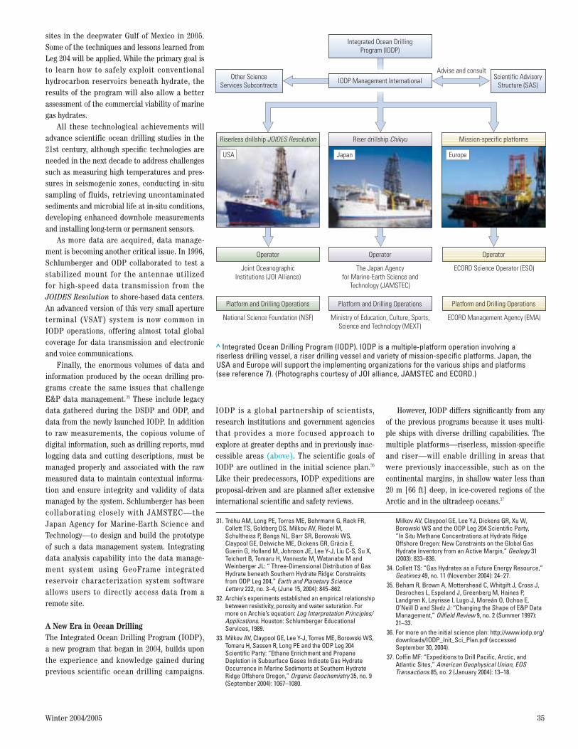
IODP is a global partnership of scientists,research institutions and government agenciesthat provides a more focused approach toexplore at greater depths and in previously inac-cessible areas (above). The scientific goals ofIODP are outlined in the initial science plan.36
Like their predecessors, IODP expeditions areproposal-driven and are planned after extensiveinternational scientific and safety reviews.
However, IODP differs significantly from anyof the previous programs because it uses multi-ple ships with diverse drilling capabilities. Themultiple platforms—riserless, mission-specificand riser—will enable drilling in areas thatwere previously inaccessible, such as on the continental margins, in shallow water less than20 m [66 ft] deep, in ice-covered regions of theArctic and in the ultradeep oceans.37
31. Tréhu AM, Long PE, Torres ME, Bohrmann G, Rack FR,Collett TS, Goldberg DS, Milkov AV, Riedel M, Schultheiss P, Bangs NL, Barr SR, Borowski WS, Claypool GE, Delwiche ME, Dickens GR, Gràcia E, Guerin G, Holland M, Johnson JE, Lee Y-J, Liu C-S, Su X,Teichert B, Tomaru H, Vanneste M, Watanabe M andWeinberger JL: “ Three-Dimensional Distribution of GasHydrate beneath Southern Hydrate Ridge: Constraintsfrom ODP Leg 204,” Earth and Planetary Science Letters 222, no. 3–4, (June 15, 2004): 845–862.
32. Archie’s experiments established an empirical relationshipbetween resistivity, porosity and water saturation. Formore on Archie’s equation: Log Interpretation Principles/Applications. Houston: Schlumberger Educational Services, 1989.
33. Milkov AV, Claypool GE, Lee Y-J, Torres ME, Borowski WS,Tomaru H, Sassen R, Long PE and the ODP Leg 204 Scientific Party: “Ethane Enrichment and Propane Depletion in Subsurface Gases Indicate Gas HydrateOccurrence in Marine Sediments at Southern HydrateRidge Offshore Oregon,” Organic Geochemistry 35, no. 9(September 2004): 1067–1080.
> Integrated Ocean Drilling Program (IODP). IODP is a multiple-platform operation involving ariserless drilling vessel, a riser drilling vessel and variety of mission-specific platforms. Japan, theUSA and Europe will support the implementing organizations for the various ships and platforms (see reference 7). (Photographs courtesy of JOI alliance, JAMSTEC and ECORD.)
Riserless drillship JOIDES Resolution
Joint OceanographicInstitutions (JOI Alliance)
The Japan Agencyfor Marine-Earth Science and
Technology (JAMSTEC)
ECORD Science Operator (ESO)
Riser drillship Chikyu Mission-specific platforms
Integrated Ocean DrillingProgram (IODP)
Scientific AdvisoryStructure (SAS)
Other ScienceServices Subcontracts
Advise and consultIODP Management International
OperatorOperator Operator
National Science Foundation (NSF) Ministry of Education, Culture, Sports,Science and Technology (MEXT)
ECORD Management Agency (EMA)
Platform and Drilling OperationsPlatform and Drilling Operations Platform and Drilling Operations
USA Japan Europe
Milkov AV, Claypool GE, Lee YJ, Dickens GR, Xu W,Borowski WS and the ODP Leg 204 Scientific Party, “In Situ Methane Concentrations at Hydrate Ridge Offshore Oregon: New Constraints on the Global GasHydrate Inventory from an Active Margin,” Geology 31(2003): 833–836.
34. Collett TS: “Gas Hydrates as a Future Energy Resource,”Geotimes 49, no. 11 (November 2004): 24–27.
35. Beham R, Brown A, Mottershead C, Whitgift J, Cross J,Desroches L, Espeland J, Greenberg M, Haines P, Landgren K, Layrisse I, Lugo J, Moreán O, Ochoa E,O’Neill D and Sledz J: “Changing the Shape of E&P DataManagement,” Oilfield Review 9, no. 2 (Summer 1997):21–33.
36. For more on the initial science plan: http://www.iodp.org/downloads/IODP_Init_Sci_Plan.pdf (accessed September 30, 2004).
37. Coffin MF: “Expeditions to Drill Pacific, Arctic, andAtlantic Sites,” American Geophysical Union, EOSTransactions 85, no. 2 (January 2004): 13–18.
The current US vessel, JOIDES Resolution,will be used in the first operational phase ofriserless operations, which lasts through 2005.38
The mission-specific platforms (MSPs) operatedby the European Consortium for Ocean ResearchDrilling will operate in shallow waters and ice-covered regions.39 As the name mission-specificsuggests, these drilling platforms could bedrilling barges, jackup rigs or seafloor drillingsystems, depending on the drilling environment.
The construction of the riser platform anddevelopment of related technologies were initi-ated in 1990 by MEXT (Ministry of Education,Culture, Sports, Science and Technology) inJapan. This program, called Ocean Drilling inthe 21st Century, was integrated into the IODP.40
The Japanese vessel, the Chikyu, meaning“Earth” will be a state-of-the-art, riser-equipped,dynamically positioned drillship. Chikyu willinitially reach a total depth of 10,000 m[32,800 ft], in water depths of up to 2,500 m[8,200 ft]. In riserless operations, Chikyu willbe able to drill in water depths of up to 7,000 m[22,970 ft].
In the future, Chikyu will be able to drillwith a riser in 4,000-m [13,120-ft] water depth toreach a total depth of 12,000 m [39,370 ft],allowing access to regions where the presence ofhydrocarbons or other fluids has previously pre-vented scientific drilling. Although riser drillingis commonly used for hydrocarbon explorationand development, it has never been used in suchultradeep environments. It will be possible todrill boreholes that are more stable, and thatcan penetrate zones with different pressures.Seismogenic zones in particular are difficult todrill because of heavy fluid losses associatedwith fractured intervals. Using this vessel,researchers can drill and install permanent sensors in seismogenic zones. Chikyu is expectedto be operational in late 2006 or early 2007.
IODP began its operations in 2004, with Expedition 301 using the riserless drillship andExpedition 302 using a mission-specific platform.The goal of Expedition 301 was to research thehydrogeology within the oceanic crust, determinefluid distribution pathways, establish linkagesbetween fluid circulation, chemical alterationand microbial processes and to determine therelationship between seismic and hydrologicalproperties.41 Expedition 301 was completed inAugust 2004, at the Juan de Fuca ridge, easternPacific Ocean. At this active hydrothermal system, molten lava from the Earth’s interior isreleased into colder ocean waters. Several hostile-environment wireline tools developed forthe oil and gas industry to explore deeper reser-voirs at extreme temperatures and pressureswere used in Expedition 301.42
Expedition 301 also collected sediments,basalt, fluids and microbial samples. Two new borehole observatories were established as deep as 583 m [1,913 ft] beneath the seafloor. Hydrogeologic tests were conducted in these boreholes.
In the future, a network of such boreholeobservatories will enable the study of fluid move-ment. Water circulation through the oceaniccrust has implications on land, particularlywhere oceanic plates sink beneath the continen-tal plates. For example, the recent volcanicactivity at Mount St. Helens, Washington, USA, inOctober 2004, is due to the combining of waterwith molten rock when the oceanic plate subducted into the Earth’s interior. Water indeep subduction zones is geochemically reactivewith the surrounding rocks, and may also affectdeep faulting.43
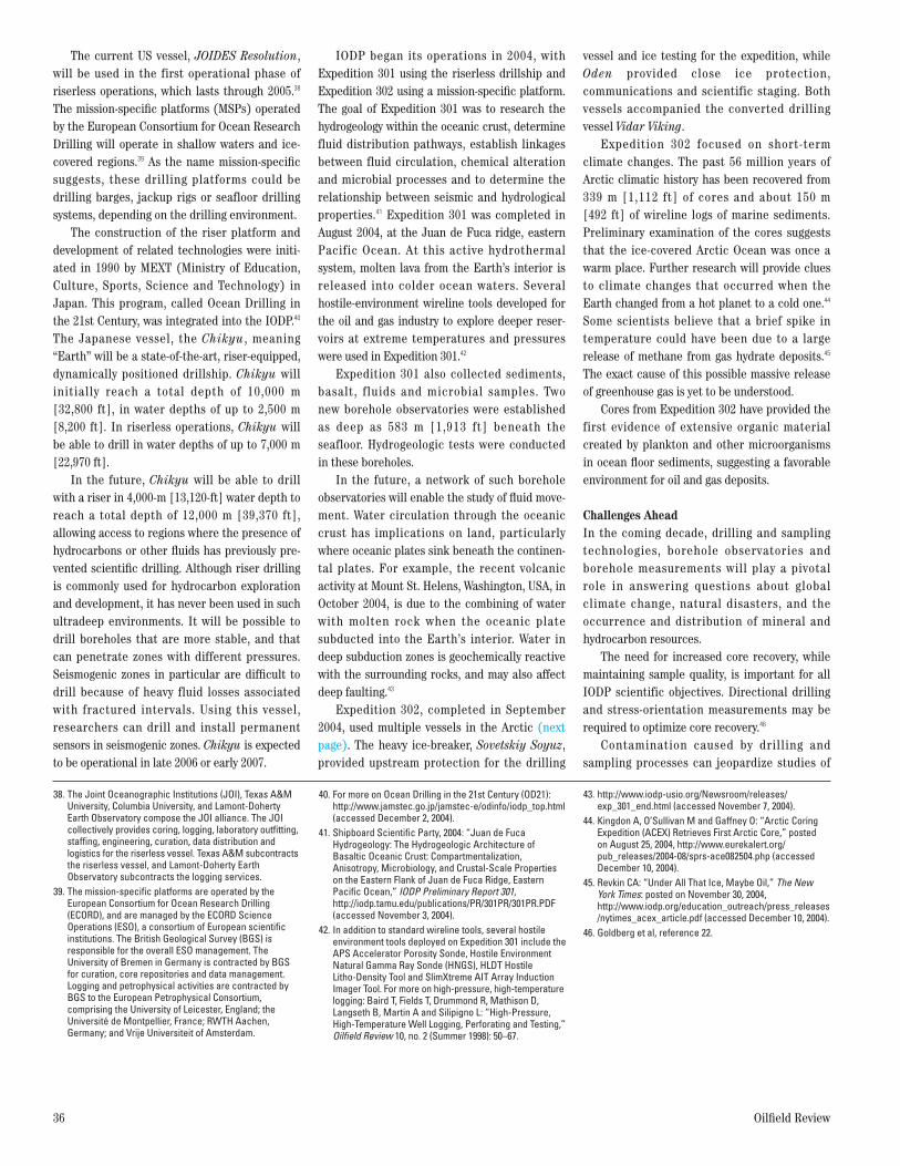
Expedition 302, completed in September2004, used multiple vessels in the Arctic (nextpage). The heavy ice-breaker, Sovetskiy Soyuz,provided upstream protection for the drilling
vessel and ice testing for the expedition, whileOden provided close ice protection, communications and scientific staging. Both vessels accompanied the converted drilling vessel Vidar Viking.
Expedition 302 focused on short-term climate changes. The past 56 million years ofArctic climatic history has been recovered from339 m [1,112 ft] of cores and about 150 m[492 ft] of wireline logs of marine sediments.Preliminary examination of the cores suggeststhat the ice-covered Arctic Ocean was once awarm place. Further research will provide cluesto climate changes that occurred when theEarth changed from a hot planet to a cold one.44
Some scientists believe that a brief spike in temperature could have been due to a largerelease of methane from gas hydrate deposits.45
The exact cause of this possible massive releaseof greenhouse gas is yet to be understood.
Cores from Expedition 302 have provided thefirst evidence of extensive organic material created by plankton and other microorganismsin ocean floor sediments, suggesting a favorableenvironment for oil and gas deposits.
Challenges AheadIn the coming decade, drilling and samplingtechnologies, borehole observatories and borehole measurements will play a pivotal role in answering questions about global climate change, natural disasters, and the occurrence and distribution of mineral andhydrocarbon resources.
The need for increased core recovery, whilemaintaining sample quality, is important for allIODP scientific objectives. Directional drillingand stress-orientation measurements may berequired to optimize core recovery.46
Contamination caused by drilling and sampling processes can jeopardize studies of
36 Oilfield Review
38. The Joint Oceanographic Institutions (JOI), Texas A&MUniversity, Columbia University, and Lamont-DohertyEarth Observatory compose the JOI alliance. The JOIcollectively provides coring, logging, laboratory outfitting,staffing, engineering, curation, data distribution and logistics for the riserless vessel. Texas A&M subcontractsthe riserless vessel, and Lamont-Doherty Earth Observatory subcontracts the logging services.
39. The mission-specific platforms are operated by the European Consortium for Ocean Research Drilling(ECORD), and are managed by the ECORD Science Operations (ESO), a consortium of European scientificinstitutions. The British Geological Survey (BGS) isresponsible for the overall ESO management. The University of Bremen in Germany is contracted by BGSfor curation, core repositories and data management.Logging and petrophysical activities are contracted byBGS to the European Petrophysical Consortium, comprising the University of Leicester, England; the Université de Montpellier, France; RWTH Aachen, Germany; and Vrije Universiteit of Amsterdam.
40. For more on Ocean Drilling in the 21st Century (OD21):http://www.jamstec.go.jp/jamstec-e/odinfo/iodp_top.html(accessed December 2, 2004).
41. Shipboard Scientific Party, 2004: “Juan de Fuca Hydrogeology: The Hydrogeologic Architecture ofBasaltic Oceanic Crust: Compartmentalization,Anisotropy, Microbiology, and Crustal-Scale Propertieson the Eastern Flank of Juan de Fuca Ridge, EasternPacific Ocean,” IODP Preliminary Report 301,http://iodp.tamu.edu/publications/PR/301PR/301PR.PDF(accessed November 3, 2004).
42. In addition to standard wireline tools, several hostileenvironment tools deployed on Expedition 301 include theAPS Accelerator Porosity Sonde, Hostile EnvironmentNatural Gamma Ray Sonde (HNGS), HLDT Hostile Litho-Density Tool and SlimXtreme AIT Array InductionImager Tool. For more on high-pressure, high-temperaturelogging: Baird T, Fields T, Drummond R, Mathison D,Langseth B, Martin A and Silipigno L: “High-Pressure,High-Temperature Well Logging, Perforating and Testing,”Oilfield Review 10, no. 2 (Summer 1998): 50–67.
43. http://www.iodp-usio.org/Newsroom/releases/exp_301_end.html (accessed November 7, 2004).
44. Kingdon A, O’Sullivan M and Gaffney O: “Arctic CoringExpedition (ACEX) Retrieves First Arctic Core,” posted on August 25, 2004, http://www.eurekalert.org/pub_releases/2004-08/sprs-ace082504.php (accessedDecember 10, 2004).
45. Revkin CA: “Under All That Ice, Maybe Oil,” The NewYork Times: posted on November 30, 2004,http://www.iodp.org/education_outreach/press_releases/nytimes_acex_article.pdf (accessed December 10, 2004).
46. Goldberg et al, reference 22.

Winter 2004/2005 37
microbiology, fluid composition and paleo-magnetism. The occurrence and distribution ofmicrobial populations are a focus of futureresearch. Samples will be collected from a rangeof tectonic and environmental settings that willutilize the multiple platforms in IODP. With riserdrilling, for the first time, direct samples will beobtained from the area of coupling between thecontinental and oceanic plates. Contamination-free samples are crucial to the success of thesestudies. Finally, pressurized coring techniqueswill need to be developed further to retrievesamples at in-situ conditions, maintaining thepressure and temperature. This is particularlyimportant in sediments containing hydrocarbonsand gas hydrates.
Another prime goal of future expeditions willbe to study seismogenic zones by drilling to theepicenter of earthquakes and placing permanentmonitoring devices that track temporal changesin temperature, pore pressure, fluid chemistry,tilt, stress and strain. Temperatures can reach
250°C [482°F] in seismogenic zones and 400°C[752°F] in hydrothermal areas. However, current downhole sensors can withstand temperatures only up to 150°C [302°F] for long-term monitoring.
Schlumberger Kabushiki Kaisha (SKK) Technology Center in collaboration with JAMSTEC has performed a feasibility study onpermanent monitoring technology and its appli-cability for long-term monitoring in scientificdeep-ocean wells. Generally, the temperatureand pressure ratings of the scientific instru-ments used in the past are not suitable. Anothermajor problem is the amount of power requiredto monitor seismicity continuously, for periodslonger than a year, and the reliability of thedownhole monitoring system. Schlumberger hasbegun a new project to develop low-powertelemetry and a power-delivery system for next-generation permanent monitoring sensors.
Scientific research on marine gas hydratescontinues to be a focus area in the IODP pro-
gram. Knowing the occurrence and distributionof gas hydrates, understanding their role in theglobal carbon cycle and evaluating their potential as an energy resource continue to beimportant objectives. The diverse drilling platforms will enable sampling and boreholemeasurements from different depths and envi-ronments. New technology will be needed, notonly to directly measure gas hydrate properties,but also to monitor pressure, temperature andfluid flow over extended time periods. Boreholeobservatories will play a vital role in the future.
Finally, the enormous quantity of data gathered over the coming years—seismic surveys, logs, cored samples, data from boreholeobservatories, documents and reports—must bestored in databases for easy access by the global scientific community. A continuing close partnership between the scientific communityand service providers is necessary to developtools and processes to address these challengesin the years ahead. —RG
60°W
120°W
60°E
0°
180°
GREENLAND
ACEX sites
SVALBARD
Lomon
osov Ridge
< An example of an MSP operation (Expedition 302) in the Arc-tic. The first Arctic coring expedition (ACEX) was conductedfrom August to September 2004, at the crest of the LomonosovRidge in the central Arctic Ocean (left). The Vidar Viking drill-ship (right) was protected by two icebreakers Oden andSovetskiy Soyuz. Vidar Viking drilled five boreholes at four sites,and a 339-m [892-ft] long sedimentary sequence was recoveredin the cores. (Photograph courtesy of M. Jakobsson, IODP.)