Embed Size (px)
DESCRIPTION
research, design, patent
Citation preview

Patrick Shao-Kai PeiScience & Design Portfolio
1

The place I stay now
The place I had been travelled
2

Patrick Shao-Kai PeiAddress: No.2-9, Ln. 140, Sec. 2, Zhongzheng Rd.,
Tamsui Dist., New Taipei City 251, Taiwan (R.O.C.)
Tel: 011 886 2 2805-3080
Mobile Phone: 011 886 921954753
Email: [email protected]/ [email protected]
EDUCATIONAL QUALIFICATIONS
2005 ~ 2007 Master of Chemical Engineering, National Taiwan University of Science and Technology, Taiwan
2003 ~ 2005 Bachelor of Chemical Engineering National Taiwan University of Science and Technology, Taiwan
1999 ~ 2003 Five Year Junior College of Chemical EngineeringMing-Chi Institute of Technology, Taiwan
KEY STRENGTHS
Over 100 US patents ( 17 issued patents ; 104 filed patents )
6 years experience in sensor, solar cell, optical thin film , dielectric material fabrication
2 years electronic system design with teamwork
Manage 700 labors of Chinese factory to build new electronic products into mass production for the world’s customers
WORK EXPERIENCE
2008 – Present Assistant Supervisor, Hon-Hai Precision Industry (Foxconn), Tucheng Taiwan/China
2007 – 2008 Semiconductor thin film engineer, VIS Specialty IC Foundry, Hsinchu Taiwan
Concept invention design and filled the patentsDeveloped camera module’s production line in ChinaDesigned PVD sputtering system in Taipei R&D centerWorked with Apple, Nokia, HP, SONY and Nintendo to develop IR-cut filter and lens anti-reflection (AR) coating project in camera modules lineDeveloped blue glass of IR-cut filter, cost down for Apple customerDeveloped hard coating on molding glass, coating variable of alloy materialsDeveloped EMI sputtering line in China
Worked with VIS partner with leading flash design house to develop 0.18 / 0.13um flash/embedded flash processDeveloped CMOS process from 0.18-micron to 0.6-micron can meet the wide range of IC design requirementsTransferred product tasks of CMOS process between factoryReaseach and develop variety material including AlCu, TiN, Si3N4, WSix and SiO2 to produce poly/metal or polysilicon/metal layers by PVD and PECVEDChecked wafer defect rate and controlled it in higher yield rate for higher reliability
3

HONORS
2009 – 2011 Patent genius prizes for 1st rank in company awarded by Hon-Hai CEO, Terry Guo
2006– 2007 Outstanding nanomaterial research at Taiwan National Science Council project - (NSC 94-2120-M-011-001), awarded $1,000,000 USD research fund
2004 – 2005 Outstanding students in chemical engineering, Ming-Chi Institute of Technology, Taiwan
2004 – 2005 Formosa Plastics Group scholarship, Taiwan
2003 - 2004 USC scholarship, Canada
PUBLICATIONS
Fang-Tso Liu, Shiang-Fu Gao, Shao-Kai Pei, Shih-Cheng Tseng, Chin-Hsin J. Liu., ZnO nanorod gas sensor for NO2 detection. JTICE 2009, 40(5), 528-532.
Shao-Kai Pei, C.J. Liu, Y.S. Huang, D.S. Tsai, “Quartz crystal microbalance sensor based on partially reduced IrO2”, The 7 th East Asian Conference on Chemical Sensors, December 3-5, 2007, Singapore [NSC 94-2120-M-011-001]
Shao-Kai Pei, Chin-Hsin J. Liu, Ying-Sheng Huang, Dah-Shyang Tsai., Gas sensing Properties of IrO2 nanorod., 2007 Chemical Sensor Conference, I-SHOU University, Taiwan [NSC 94-2120-M-011-001]
4
Patrick Shao-Kai Pei
PROFESSIONAL COATING EXPERIENCE
� Metal organic chemical vapor deposition (MOCVD):Deposited IrO2 nanorod by controlling different substrate temperature and precursor concentration. Furthermore, our team inventeda useful technique to reduced IrO2
become Ir/IrO2 co-existed or Ir existed independently on quartz crystal microbalance (the evidence by XRD, XPS investigation), Ir/IrO2 or Ir nanorod surface had higheroxygen vacancies to make sensor more sensitivity and good electrical properties. This successful achievements were showed on on my master thesis and were beenpublished at Singapore conference of Nanyang Technological University.� Ion beam plasma vacuum deposition: Deposited metal oxide, for example, TiO2/SiO2 multilayer on anti-reflection (AR) coating and infrared light cut filter. Controlled parameters such as ion source energy, crucible rotated rate, source evaporated rate and substrate temperature (dorm substrate) to get higher density of optical thin film. It was used on plastic lens coating which physical parameters such as transmittance and reflectance were detected by UV-vis spectrometer. In addition, use Optical thin film simulation of Macleod & TFCalc todesign color filter coating layers mixing with high and low refractive thin film to meet customer spec, for example, IR-cut_TiO2/SiO2_42 layers met Tave% > 95% at wavelength 420nm~680nm and Tave% < 2% at wavelength 700nm~1200nm ; AR_TiO2(Ta2O5)/SiO2_6~8 layers met Tave% > 99% at wavelength 420nm~680nm. � In-line sputtering (multiple cathode):The system coated Cu/SUS EMI sputtering to avoid electromagnetic disturbance, plastic decoration, light guide plate coated CrN used in dashboard, solar cell AR coating.� Reactive magnetron sputtering deposition: Sputtering TiO2 as seed layer on quartz for gas sensor, AlCu, TiN, Si3N4, WSix and SiO2 to produce poly/metal or polysilicon/metal layers or Pt-Ir-Ni 0.8~1.1um as protective layers on molding jig to mold optical glass….etc� Aerosol spray pyrolysis: Build system by myself, invented rapid, low cost, and non-vacuum nebulization system, combined the system with hydrothermal system to manufacture many kinds of transition metal oxide (TiO2, RuO2, IrO2, ZnO…), ZnO nanorod had been used on NO2 gas sensing, which successful achievements had been published on journal papers� Sol-gel method: combined it with my invented aerosol spray pyrolysis system to do dye-sensitized solar cell device (DSSC, SnO2:F/TiO2(by spray)/N3-dye (by sol-gel) ), this device had 3% ~ 4% solar efficiency

SOFTWARE / GRAPHIC DESIGN TOOLS
SolidWorks, ProE, MINITAB, MATLAB, Macleod, TFCalc, SEM, ESCA, TEM, UV spectrometer, XRD, Raman spectrometer
REFERENCE
Jen Tsorng Chang Assistant Vice President
Foxconn [email protected]
Dah-Shyang Tsai Professor
National Taiwan University of Science and Technology [email protected]
Chin-Hsin J. Liu Professor
National Taiwan University of Science and Technology [email protected]

PATENT PUBLICATIONS 6
Research Experience (I) 70
Research Experience (II) 73
Statement of Purpose 78
6

Patent Publications13 issued patents ; 83 filled patents
7

Issued (13+)
Public (83+)
URL: http://www.patentbuddy.com/Inventor/PEI-SHAO-KAI/12465796
Patents and Applications
1 8,293,081 Physical vapor deposition device
2 8,277,289 Multi-functional grinding apparatus
3 8,272,344 Wet coating system having annealing chamber
4 8,257,547 Surface activation device
5 8,257,151 Polishing device
6 8,250,739 Multi-functional assembly device
7 8,251,013 Vapor deposition device
8 8,251,779 Grinding device with cleaning assembly
9 8,246,421 Arc surface grinding device
10 8,246,795 Lens module fabrication method
11 8,211,320 Carbon nanotube device and method for making same
12 8,007,019 Clamp having symmetrical configuration
13 8,009,980 Light blocking plate, camera module having same, and method for making same
2010/0058,981 FILM COATING APPARATUS
2010/0051,717 ULTRASONIC ATOMIZER
2010/0037,913 CLEANING APPARATUS AND METHOD FOR CLEANING GLUE
2010/0288,314 EVAPORATION MATERIAL CLEANING APPARATUS
2010/0275,838 COATING APPARATUS
2010/0270,153 GAS SENSING SYSTEM WITH QUARTZ CRYSTAL SUBSTRATE
2010/0252,427 MAGNETRON SPUTTERING TARGET AND MAGNETRON SPUTTERING SYSTEM
2010/0170,443 FILM MANUFACTURING DEVICE
2010/0126,578 WORKING ELECTRODE, DYE-SENSITIZED SOLAR CELL HAVING SAME AND METHOD FOR MAKING SAME
PUB. APP. NO. Title
2011/0020,486 DEVICE FOR FORMING FILM
2011/0011,339 COATING APPARATUS
2011/0000,429 FILM COATING APPARATUS
2010/0319,622 FILM COATING APPARATUS FOR CHEMICAL VAPOR DEPOSITION AND PHYSICAL VAPOR DEPOSITION
2010/0294,658 MAGNETRON SPUTTERING DEVICE HAVING ROTATABLE SUBSTRATE HOLDER
2010/0288,630 PHYSICAL VAPOR DEPOSITION DEVICE
8

2012/0260,956 CLEANING DEVICE FOR CLEANING HOLDER OF LENS MODULE
PUB. APP. NO.
2012/0048,187 COATING HOLDER AND COATING DEVICE HAVING SAME
2012/0048,199 CRUCIBLE AND EVAPORATION DEPOSITION DEVICE HAVING SAME
2012/0048,475 FIXING DEVICE AND GLASS MANUFACTURING DEVICE USING THE SAME
2012/0048,308 LENS CLEANING APPARATUS
2012/0037,075 COATING APPRATUS HAVING CONCENTRATION SENSOR
2012/0037,076 MULTI-ENVIRONMENT COATING DEVICE
2012/0040,593 COATING AND CYLINDRICAL GRINDING APPARATUS
2012/0021,678 CYLINDRICAL GRINDING AND POLISHING DEVICE
2012/0012,050 APPARATUS FOR PROCESSING COATING MATERIAL AND EVAPORATION DEPOSITION DEVICE HAVING SAME
2012/0012,051 DRUM COATING DEVICE
2012/0012,056 APPARATUS FOR PROCESSING COATING MATERIAL AND EVAPORATION DEPOSITION DEVICE HAVING SAME
2012/0015,591 GLASS MANUFACTURING DEVICE
2012/0097,098 COATING APPRATUS HAVING TWO COATING DEVICES FOR SUCCESSIVELY COATING SAME SURFACE OF SUBSTRATE
2012/0090,442 GLASS CUTTING DEVICE
2012/0088,437 GLASS MANUFACTURING DEVICE
2012/0073,499 COATING DEVICE
2012/0077,423 SANDBLASTING APPARATUS
2012/0073,965 MAGNET MOUNTING SYSTEM AND MAGNETRON SPUTTERING DEVICE HAVING SAME
2012/0064,807 SANDBLASTING APPARATUS
2012/0260,956 CLEANING DEVICE FOR CLEANING HOLDER OF LENS MODULE
2012/0006,267 APPARATUS FOR PROCESSING COATING MATERIAL AND EVAPORATION DEPOSITION DEVICE HAVING SAME
2011/0314,983 CUTTING DEVICE AND CUTTING APPARATUS HAVING SAME
2011/0314,985 CUTTING APPARATUS
2011/0318,998 POLISHING DEVICE
2011/0308,456 COATING APPARATUS
2011/0312,252 SANDBLASTING APPARATUS AND METHOD FOR SHAPING PRODUCT WITH SAME
Title
9

2011/0297,602 LIQUID PURIFYING APPARATUS AND SUBSTRATE CLEANING APPARATUS
2011/0297,607 LIQUID PURIFYING APPARATUS
2011/0283,938 LENS BARREL COATING AID APPARATUS
2011/0283,943 VAPOR DEPOSITION APPARATUS
2011/0271,909 COATING APPARATUS
2011/0266,148 TARGET BASE AND SPUTTERING APPARATUS USING SAME
2011/0267,684 LIGHT BLOCKING PLATE, LENS MODULE HAVING SAME, AND METHOD FOR MAKING SAME
2011/0266,028 CONDUCTIVE FILM AND METHOD FOR MAKING SAME
2011/0259,738 MAGNETRON SPUTTERING DEVICE
2011/0259,266 COATING SYSTEM
2011/0259,267 FILM COATING HOLDER
2011/0253,531 COMPOSITE COATING APPARATUS
2011/0253,036 WET-COATING APPARATUS
2011/0253,038 SPIN COATING DEVICE
2011/0253,041 DIP COATING APPARATUS
2011/0247,558 COATING HOLDER AND COATING DEVICE HAVING SAME
2011/0232,572 PLASMA FILM-COATING APPARATUS
2011/0203,736 SURFACE ACTIVATION DEVICE
2011/0192,346 COATING DEVICE
2011/0185,968 COATING DEVICE
2011/0179,994 COATING APPARATUS
2011/0177,307 CARBON NANOTUBE DEVICE AND METHOD FOR MAKING SAME
2011/0155,053 APPARATUS FOR MAKING WORKING ELECTRODE OF DYE-SENSITIZED SOLAR CELL
2011/0155,055 CVD DEVICE
PUB. APP. NO. Title
10

2011/0155,562 LENS MODULE FABRICATION METHOD
2011/0159,792 MULTI-FUNCTIONAL GRINDING APPARATUS
2011/0126,763 VAPOR DEPOSITION DEVICE
2011/0126,766 COATING APPARATUS
2011/0088,615 DIP COATING APPARATUS
2011/0073,472 COATING APPARATUS
2011/0065,367 ARC SURFACE GRINDING DEVICE
2011/0052,180 LIGHT BLOCKING PLATE, CAMERA MODULE HAVING SAME, AND METHOD FOR MAKING SAME
2011/0053,472 GRINDING DEVICE WITH CLEANING ASSEMBLY
2011/0047,787 MULTI-FUNCTIONAL ASSEMBLY DEVICE
2011/0048,321 COATING APPARATUS
2011/0035,890 AUTOMATIC CLEANING APPARATUS
2011/0036,293 VAPOR DEPOSITION DEVICE
2011/0030,614 WET COATING SYSTEM HAVING ANNEALING CHAMBER
2011/0031,108 SPUTTERING DEPOSITION METHOD AND APPARATUS
2011/0031,116 MAGNETRON SPUTTERING TARGET ASSEMBLY AND COATING APPARATUS HAVING SAME
2011/0024,290 MAGNETIC DEVICE AND MAGNETRON SPUTTERING DEVICE USING THE SAME
2011/0017,136 COATING DEVICE
PUB. APP. NO. Title
11

PEI, SHAO-KAI
HON HAI PRECISION INDUSTRY CO., LTD
Tu-Cheng, TW
On-line check more patent detail:
http://www.patentbuddy.com/Inventor/PEI-SHAO-KAI/12465796
12

LIGHT BLOCKING PLATE, CAMERA MODULE HAVING
SAME, AND METHOD FOR MAKING SAME
An exemplary light blocking plate includes a light pervious substrate, a filter film formed on the light pervious substrate,
and a metal film layer formed on the light pervious substrate and the optical filter film. The metal film layer defines a
through hole to expose a central portion of the optical filter film.
Application number: 12/758,038Publication number: US 2011/0052180 A1Filing date: Apr 12, 2010Issued patent: US8009980 (Issue date Aug 30, 2011)
13

Clamp having symmetrical configuration
A clamp includes a pivot, a first lever, a second lever, and two stretched resilient members. The first and
second levers are pivotally coupled to each other via the pivot. Each of the first and second levers includes
a first handle and, a second handle arranged at opposite sides of the pivot. Each of the first and second
levers includes a first jaw member arranged on a distal end of the second handle thereof and a second jaw
member arranged on a distal end of the first handle. One of the stretched resilient members is
interconnected between the first handle of the first lever and the second handle of the second lever, and
the other of the stretched resilient member being interconnected between the second handle of the first
lever and the first handle of the second lever.
Patent number: 8007019
Filing date: Aug 14, 2010
Issue date: Aug 30, 2011
Application number: 12/856,645
14

APPARATUS FOR MAKING WORKING
ELECTRODE OF DYE-SENSITIZED SOLAR CELL
Application number: 12/788,306Publication number: US 2011/0155053 A1Filing date: May 27, 2010
An apparatus for making a working electrode of a dye-sensitized solar cell is provided. The apparatus
includes a columnar body, a rotatable mechanism rotatably received in the columnar body, and a
cover enclosing the columnar body. Accommodating grooves are formed in the columnar body
configured to accommodate substrates. The rotatable mechanism includes a containing chamber,
rollers, and nozzles. The nozzles are configured for jetting the slurry from the containing chamber to
the accommodating grooves. The rollers are independently rotatable and configured for rolling the
slurry on the substrates. The cover has feeding tubes and exporting tubes extending therethrough.
The feeding tubes are in communication with the containing chamber and configured for feeding the
slurry to the containing chamber. The exporting tubes are in communication with the columnar body
and configured for evacuating excess slurry from the columnar body.
15

CVD DEVICE
A CVD device includes a reaction chamber, a support device, a gas input assembly and a gas output device. The support device is
positioned in the reaction chamber. The gas input assembly and a gas output assembly are connected to the reaction chamber
respectively. The gas input assembly includes a main body positioned in the reaction chamber and a plurality of gas jets uniformly
positioned on the main body, introducing mixed gas to the reaction chamber uniformly.
Application number: 12/767,026Publication number: US 2011/0155055 A1Filing date: Apr 26, 2010
16

WORKING ELECTRODE, DYE-SENSITIZED SOLAR CELL
HAVING SAME AND METHOD FOR MAKING SAME
Application number: 12/502,378Publication number: US 2010/0126578 A1Filing date: Jul 14, 2009
An exemplary working electrode includes a transparent conductive substrate, a nanorod layer formed on the transparent
conductive substrate, and a porous semiconductor layer formed on the nanorod layer. The nanorod layer includes a plurality of
nanorods. Each nanorod is comprised of a material selected from the group consisting of iridium-iridium oxide and ruthenium-
ruthenium oxide. The porous semiconductor layer has a dye sensitizer adsorbed thereon
17

COATING APPARATUS
A coating apparatus includes a chamber device and a transporting device. The chamber device defines two coating chambers, two
parallel coating channels, and a transportation channel communicating with the coating channels. The coating chambers are
separated from each other. The coating chambers and the coating channels are alternately arranged. Each coating chamber
defines at least one coating slot communicating with the respective coating channel. The transporting device includes a shaft
rotatable with respect to the chamber device and a carrying board fixed on the shaft. The shaft is axially movable in the
transportation channel. The carrying board is receivable in each of the coating channels for exposing a substrate to the
corresponding coating chamber via the associated coating slot. The carrying board is rotatable about the shaft in each of the
coating channels and jointly movable with the shaft in and along the transportation channel between the coating channels.
Application number: 12/732,200Publication number: US 2010/0275838 A1Filing date: Mar 26, 2010
18

An ultrasonic atomizer includes a container, a separating membrane and an ultrasonic oscillator. The container defines an inner
chamber therein. The separating membrane is disposed in the inner chamber. The separating membrane partitions the inner
chamber into a bottom chamber and a top chamber, the bottom chamber is filled with a noncorrosive liquid. The ultrasonic
oscillator is received in the bottom chamber and submerged in the liquid.
ULTRASONIC ATOMIZERApplication number: 12/470,472Publication number: US 2010/0051717 A1Filing date: May 21, 2009
19

MAGNETIC DEVICE AND MAGNETRON
SPUTTERING DEVICE USING THE SAME
Application number: 12/796,620Publication number: US 2011/0024290 A1Filing date: Jun 8, 2010
A magnetron sputtering device includes a base arranged adjacent to a sputtering target, and a plurality of movable magnet
assemblies. Each movable magnet assembly includes a support fixed to the base, and a plurality of magnets that are connected
to each other, arranged on the support and comprising opposing poles facing the base. Each movable magnet assembly also
includes a driving device to drive the plurality of magnets to slide with respect to the support.
20

AUTOMATIC CLEANING APPARATUS
An exemplary cleaning apparatus includes a cleaning member, a connecting member, a drying member, and a workpiece holder. The
connecting member includes a main housing defining two opposite surfaces and two blocks received in the main housing. The main
housing defines a first chamber and two second chambers communicating with the first chamber, each of the second chambers
extending through to one of the two opposite surfaces and near to the other opposite surface. The cleaning member and the drying
member are connected to the two opposite surfaces and communicate with each other via the first chamber. The two blocks are
movable between the first chamber the second chambers, respectively. Each block defines an engaging surface, facing the other
engaging surface. When the blocks move into the first chamber and the engaging surfaces engage with each other, the blocks shut off
communication between the cleaning member and the drying member
Application number: 12/835,703Publication number: US 2011/0035890 A1Filing date: Jul 13, 2010
21

FILM COATING APPARATUS
A film coating apparatus for coating a substrate includes a number of film coating units. Each film coating unit includes a
container, a transfer roller, a liquid jet, and a heater. The container is used for receiving coating liquid. The coating liquid
includes coating material. The transfer roller is capable of conveying the substrate. The liquid jet is configured for jetting
coating liquid received in the container toward the transfer roller. The heater is used for heating the coating liquid on the
substrate to solidify the coating material of the coating liquid on the substrate to form films.
Application number: 12/494,280Publication number: US 2010/0058981 A1Filing date: Jun 30, 2009
22

A vapor deposition device includes a holding compartment and a reaction device. The holding compartment defines a receiving
chamber and includes a number of inner side surfaces and a number of holding plates disposed on the respective inner side
surfaces, each holding plate defines a number of holding grooves for holding substrates. The reaction device is rotatably received
in the receiving chamber and includes an outer barrel and an inner barrel received in the outer barrel, the outer barrel and the
inner barrel cooperatively defines a first room, the inner barrel defines a second room; the reaction device includes ion nozzles
communicating with the second room and precursor gas nozzles communicating with the first room; the outer barrel includes at
least one crucible and at least one electron beam gun received in the first room, the inner barrel includes an ion source received in
the second room.
VAPOR DEPOSITION DEVICEApplication number: 12/718,097Publication number: US 2011/0126763 A1Filing date: Mar 5, 2010
23

MAGNETRON SPUTTERING DEVICE HAVING
ROTATABLE SUBSTRATE HOLDER
A magnetron sputtering device includes a target holder, a substrate holder, and a first driver. The target holder defines a
sputtering space therein, and includes at least one target tray arranged at a periphery of the sputtering space. The
substrate holder is rotatably positioned in the sputtering space. The first driver is connected to the substrate holder. The
first driver is operable to rotate the substrate holder relative to the target holder.
Application number: 12/568,800Publication number: US 2010/0294658 A1Filing date: Sep 29, 2009
24

MAGNETRON SPUTTERING TARGET AND
MAGNETRON SPUTTERING SYSTEM
A magnetron sputtering target comprises a magnetron device and a target positioned in a magnetic field of the magnetron
device. The magnetron device comprises a metal plate, a plurality of first magnets and second magnets. A direction of the
magnetic lines of the first magnets is opposite to that of the second magnets. The first magnets and the second magnets
are embedded in the metal plate and arranged in a number of rows and columns. At least one first magnet is adjacent to a
second magnet in one row, and at least one first magnet is adjacent to a second magnet in one column, therefore, there are
magnetic lines in row direction and column direction exist in the magnetic field of the magnetron device.
Application number: 12/753,123Publication number: US 2010/0252427 A1Filing date: Apr 2, 2010
25

LENS MODULE FABRICATION METHOD
A method for fabricating a lens module includes forming an IR-cut filter, forming a shading block on part of
a surface of the IR-cut filter, forming a blocking layer on the IR-cut filter and the shading block, forming an
electromagnetic shielding layer on the blocking layer, polishing the electromagnetic shielding layer and the
blocking layer to expose the shading block, removing the shading block from the IR-cut filter to form an
optical component, mounting a lens in the barrel portion adjacent to the IR-cut filter portion, and
packaging the holding portion of the optical component to a printed circuit board to form the lens module.
Application number: 12/763,128Publication number: US 2011/0155562 A1Filing date: Apr 19, 2010
26

CARBON NANOTUBE DEVICE AND METHOD FOR MAKING SAME
A carbon nanotube device includes a flexible substrate and a patterned carbon nanotube layer. The flexible substrate defines a
plurality of recesses. The patterned carbon nanotube layer is formed on the flexible substrate. The carbon nanotube layer
includes a plurality of carbon nanotube arrays. Each carbon nanotube array is fixedly attached in the corresponding recess
Application number: 12/821,146Publication number: US 2011/0177307 A1Filing date: Jun 23, 2010
27

FILM COATING APPARATUS FOR CHEMICAL VAPOR
DEPOSITION AND PHYSICAL VAPOR DEPOSITION
An exemplary film coating apparatus includes a housing, a holder for holding a workpiece, and a coating source. The housing defines a
chamber therein. The holder and the coating source are received in the chamber. The coating source includes a supporting plate and a
number of gas jetting heads. The supporting plate includes a first surface facing the holder, and defines a receiving recess at the first
surface configured for receiving a target material, and a number of through holes. The gas jetting heads are capable of introducing one
or more gases into the chamber, each gas jetting head passes through one respectively through hole and is fixed in the through hole.
Application number: 12/541,697Publication number: US 2010/0319622 A1Filing date: Aug 14, 2009
28

CLEANING APPARATUS AND METHOD FOR CLEANING GLUE
A cleaning apparatus includes a heating device, a freezing device, and a conveying belt. The heating device includes a hot water
source and a hot water container. The hot water container includes an exit shutter and defines a water inlet and a water outlet.
The hot water source being communicated to the hot water container via the water inlet. The freezing device includes an aerosol
spray system and a freezing container. The spray system includes a spray head. The freezing container includes an entrance
shutter. The spray head is received in the freezing container. The conveying belt extends into the hot water container via the exit
shutter and into the freezing container via the entrance shutter and thereby bridges the hot water container and the freezing
container.
Application number: 12/477,136Publication number: US 2010/0037913 A1Filing date: Jun 3, 2009
29

MULTI-FUNCTIONAL ASSEMBLY DEVICEApplication number: 12/691,889Publication number: US 2011/0047787 A1Filing date: Jan 22, 2010
A multi-functional assembly device includes a fixed barrel, a number of supporting boards, a rotatable barrel, and a driving device for
rotating the rotatable barrel. The fixed barrel includes a number of sidewalls and defines a chamber surrounded by the sidewalls. The
supporting boards are configured for holding the lens modules and are able to be secured on the inner surfaces of the sidewalls. The
rotatable barrel includes a main body, a number of carrying devices, a number of glue dispensers, and a number of glue solidifying
devices. The main body includes a first side surface, a second side surface, and a third side surface facing the inner surfaces of the
sidewalls. The carrying devices, the glue dispensers, and the glue solidifying devices are installed on the first side surface, the second
side surface, and the third side surface respectively.
30

COATING HOLDER AND COATING DEVICE HAVING SAMEApplication number: 12/820,056Publication number: US 2011/0247558 A1Filing date: Jun 21, 2010
A coating holder for holding a plurality of workpieces includes a rotating shaft, a first driving member, a plurality of hanging
arms, a plurality of supporting trays, and a plurality of second driving members. The first driving member is configured for
driving the rotating shaft to rotate. The hanging arms extend from the rotating shaft. Each hanging arm includes a free end
distal from the rotating shaft. The supporting trays are configured for holding the workpieces. The second driving members
are fixed in the respective free ends and are connected to the respective supporting trays. The second driving members are
configured for driving the supporting trays to rotate.
31

WET COATING SYSTEM HAVING ANNEALING CHAMBERApplication number: 12/641,581Publication number: US 2011/0030614 A1Filing date: Dec 18, 2009
An exemplary wet coating system includes a coating chamber, an annealing chamber, an unloading chamber, and a
mechanical arm. The coating chamber is configured for allowing a substrate being wet coated therein. The unloading
chamber is configured for allowing the substrate being unloaded therein. The annealing chamber is interposed between and
communicated with the coating chamber and the unloading chamber and is configured for allowing the substrate being
annealed therein. The communicated coating chamber, annealing chamber, and unloading chamber are vacuumized. The
mechanical arm is configured for holding the substrate and moving the substrate across the coating chamber, the annealing
chamber, and the unloading chamber.
32

COATING DEVICEApplication number: 12/862,725Publication number: US 2011/0192346 A1Filing date: Aug 24, 2010
A coating device includes an autoclave and a spray member. The autoclave includes an autoclave body and a cover sealing the
autoclave body. The autoclave body defines a plurality of holding grooves in an inner surface thereof for holding substrates.
The spray member is positioned on the cover and received in the autoclave body. The spray member defines openings in a
side surface thereof. The spray member includes a container and an ultrasonic atomization unit. The container defines a cavity
in communication with the openings. The ultrasonic atomization unit is received in the cavity.
33

FILM MANUFACTURING DEVICEApplication number: 12/639,141Publication number: US 2010/0170443 A1Filing date: Dec 16, 2009
A film manufacturing device for forming a film on a substrate includes a vaporizing device, a container, an absorption
tower and a film deposition device. The vaporizing device is configured for vaporizing a dopant containing solution.
The container is configured for containing a film forming solution. The absorption tower is configured for mixing the
film forming solution with the vaporized dopant containing solution to obtain a precursor solution. The film
deposition device is configured for forming the film on the substrate using the precursor solution.
34

PHYSICAL VAPOR DEPOSITION DEVICE
A physical vapor deposition device includes a chamber; a cathode and an opposite anode, a target material, and
supporting device arranged in the chamber. The target material and the supporting device are positioned between
the cathode and the anode. The supporting device includes a rotatable device and a hollow supporting plate. The
hollow supporting plate is configured for securing the workpiece and exposing part of the workpiece where is
needed to be coated. The hollow supporting plate is movably fastened to the rotatable device. A distance from the
hollow supporting plate to the rotatable device can be adjusted when the hollow supporting plate is rotated
together with the rotatable device in order to align workpiece with the target material.
Application number: 12/699,988Publication number: US 2010/0288630 A1Filing date: Feb 4, 2010
35

DEVICE FOR FORMING FILMApplication number: 12/634,828Publication number: US 2011/0020486 A1Filing date: Dec 10, 2009
A device for forming films on a substrate includes a main chamber and a reacting device. The main chamber is for
receiving the substrate. The reacting device is received in the main chamber facing the substrate. The reacting
device includes a reacting container, a supporting plate, a cover, and a collimation tube. The supporting plate and
the cover are disposed on opposite ends of the reacting container to close the reacting container. The supporting
plate is configured for supporting a target. The collimation tube is located in the reacting container to divide the
reacting container into a first chamber and a second chamber. The target is located in the first chamber, and the
cover defines a number of through holes.
36

MAGNETRON SPUTTERING TARGET ASSEMBLY
AND COATING APPARATUS HAVING SAME
A coating apparatus includes a shielding casing defining a chamber, a substrate holder received in the chamber
and a target assembly located inside the shielding casing. The substrate holder is configured to hold a substrate.
The target assembly faces the substrate. The target assembly includes a target frame, two opposite target
electrodes, a number of magnetrons and a transport unit. The target base includes two opposite end surfaces
and a number of side surfaces interconnecting the end surfaces. The two opposite target electrodes are fixed on
the two opposite side surfaces. The magnetrons are received in the receiving cavity and disposed between the
target electrodes. The transport unit is configured to carry the magnetrons to circulate therearound.
Application number: 12/758,034Publication number: US 2011/0031116 A1Filing date: Apr 12, 2010
37
PLASMA FILM-COATING APPARATUSApplication number: 12/820,057Publication number: US 2011/0232572 A1Filing date: Jun 21, 2010
An exemplary plasma film-coating apparatus includes a reaction chamber, a pipe, and a reaction
device. The reaction chamber defines a reaction cavity. The reaction cavity includes receiving
grooves defined in an inner wall of the reaction chamber. The receiving grooves are configured for
receiving workpieces. The pipe extends through the reaction chamber and is in communication
with the reaction cavity. The reaction device is rotatably connected to the reaction chamber. The
reaction device includes two electrodes and at least one precursor chamber. The two electrodes
are positioned inside the reaction cavity, and face each other. The at least one precursor chamber
is attached to a surface of one electrode away from another electrode, and extends through the
reaction chamber. The at least one precursor chamber is in communication with the reaction
cavity and is configured for providing gaseous precursor.
38

GAS SENSING SYSTEM WITH QUARTZ CRYSTAL SUBSTRATE
An exemplary gas sensing system includes a gas sensing unit, a detecting unit, and a processing unit. The
gas sensing unit includes a quartz crystal substrate, a first electrode layer, a second electrode layer, a first
activating layer, and a sensor medium layer having adsorption ability and desorption ability to chemiacal
gas. The detecting unit is electrically connected with the first electrode and the second electrode, and is
configured for detecting a frequency change of the gas sensing unit before and after adsorbing the
chemiacal gas. The processing unit is electrically connecting with the detecting unit, and is configured for
obtaining a mass change of the gas sensing unit according to the frequency change.
Application number: 12/730,248Publication number: US 2010/0270153 A1Filing date: Mar 24, 2010
39

SPUTTERING DEPOSITION METHOD AND APPARATUSApplication number: 12/844,804Publication number: US 2011/0031108 A1Filing date: Jul 27, 2010
A sputtering deposition method is utilized by a sputtering deposition apparatus including a first
chamber, a second chamber, a first carrier, and a second carrier. Some first substrates are positioned in
the first carriers in the first chamber for heating. The first carriers in the first chamber and the second
carriers in the second chamber are exchanged. The first substrates in the second chamber are
sputtered. The second carriers in the first chamber and the first carriers in the second chamber are
exchanged. The first substrates in the first chamber are taken out.
40

EVAPORATION MATERIAL CLEANING APPARATUS
An apparatus capable of cleaning a material includes pipes arranged in a first barrel; and through holes
defined in a second barrel. The second barrel is received in the first barrel. The apparatus Further
includes a driver comprising a drive shaft, the drive shaft extending through the first barrel and being
connected to the second barrel. A fluid container is included store fluid, an air controller is provided air-
dry the material. Before washing the material, the second barrel is driven by the driver to cause each of
the through holes to disengage from a corresponding pipe. After washing the material, the second
barrel is driven by the driver to cause each of the through holes to engage with the corresponding pipe.
Application number: 12/778,148Publication number: US 2010/0288314 A1Filing date: May 12, 2010
41

It is common to use more than one kind of coating process, such as, spraying, ion sputtering, vapor
deposition, or spray pyrolysis when applying multiple coats of materials such as paint or primer to a
workpiece. Generally, each coating process must be carried out within a different vacuum chamber. To
complete these multiple coating processes, the workpiece must be transported from one vacuum chamber
to another. However, during the transportation, the workpiece may be exposed to the environment and may
be contaminated.
WORKING ELECTRODE, DYE-SENSITIZED SOLAR CELL
HAVING SAME AND METHOD FOR MAKING SAME
US Patent
Application Document
42

A spin coating device includes a container and a rotating member. The container is used for holding a first solution
and includes a sidewall which a plurality of substrates are arranged on. The rotating member is rotatable within
the container and includes an inlet and at least one outlet. A second solution flows into the rotating member
through the inlet, and flows into the container through the at lease one outlet. A mixture of the first solution and
the second solution is spread onto the substrate by centrifugal force of the rotating member.
SPIN COATING DEVICE US Patent
Application Document
43

GLASS CUTTING DEVICE
A glass cutting device includes a cutter, a driver, and an ejector. The cutter includes a connection tube,
an annular blade base, and a blade. The annular blade base extends outward from an end of the
connection tube along a direction substantially parallel to a radial direction of the connection tube. The
blade extends from a surface of the blade base opposite to the connection tube along a direction
substantially perpendicular to the radial direction of the connection tube. The driver drives the
connection tube to spin and move toward a glass substrate to cut a circular glass from the glass
substrate by the blade. The ejector is received in the connection tube and ejects the circular glass from
the glass substrate.
US Patent
Application Document
44

COATING DEVICE
A coating device includes a table, a number of coating housings, a carrier, a
number of conveyors, and a number of turntables. The coating housings are separately
mounted on the table, and each including a hatch formed thereon. The hatches of all
the coating housings face towards a same direction. The carrier are used for carrying
one or more products to be coated. The conveyors are distributed on the table
around each of the coating housing, and respectively extend into the inside of the
coating housing through the hatch for delivering the carrier into the coating housings
in turn. The turntables are installed between every two adjacent conveyors for
transporting the carrier from a preceding conveyor to a succeeding conveyor
according to a predefined route, respectively.
US Patent
Application Document
45

LIQUID PURIFYING APPARATUS AND SUBSTRATE CLEANING
APPARATUS CROSS-REFERENCE TO RELATED APPLICATION
An exemplary liquid purifying apparatus includes beads in contact with the liquid, a
lighting element, and a driving member. Each bead has a purifying coating comprised
of a nanomaterial formed thereon. The lighting element has the beads positioned
thereon. The driving member is configured for driving the lighting element to rotate,
thereby rotating the beads in the liquid.
US Patent
Application Document
46

WET-COATING APPARATUS
A wet-coating apparatus includes a main body, a cleaning agent bin, a coating agent
storage bin, a hot-air injector, a heater, and a transport. The main body defines a coating
chamber. The coating chamber includes a first sub-chamber, 5 a second sub-chamber, and a
third sub-chamber located between the first and second sub-chambers. The cleaning agent
storage bin is received in the first sub-chamber. The coating agent storage bin is received in
the first sub-chamber and located adjacent to the third sub-chamber. The hot-air injector is
received in the third sub-chamber. The heater is received in the second sub-chamber. The
10 transport is located over the cleaning agent storage bin and the coating agent storage bin,
andconfigured to transport a substrate from the first sub-chamber to the second sub-chambe
US Patent
Application Document
47

COATING APPARATUS
A coating apparatus includes a first vessel, a revolving unit, and a motor having a
drive shaft. The first vessel has a receiving space defined therein for receiving
substrates and a first solution. The revolving unit is received in the receiving space and
rotatable relative to the first vessel to impart a centrifugal force to the first solution. The
drive shaft is coupled to the revolving unit. The motor is configured for rotating the
revolving unit.
US Patent
Application Document
48

CONDUCTIVE FILM AND METHOD FOR MAKING SAME
A method for making a conductive film, includes: providing a carbon nanotube film defining a
plurality of holes therein; attaching the carbon nanotube film on a substrate; adjusting a temperature
of the carbon nanotube film in a range from about 7°C to about 9°C; dropping and rubbing a
nanoparticle aqueous solution in the carbon nanotube film, the nanoparticles aqueous solution
containing a plurality of nanoparticles; and adjusting the temperature of the carbon nanotube film in a
range from about 24°C to about 26°C and drying the carbon nanotube film to obtain the conductive
film on the substrate.
US Patent
Application Document
49

MAGNETRON SPUTTERING DEVICE
A magnetron sputtering device includes a holding compartment, a target assembly, a
supporting base, and a rotation module. The holding compartment is divided to a
reactive chamber and a receiving chamber. The target assembly includes two cooling
plates, two magnetic units, and a target. The two cooling plates define a magnetron
room communicating with the receiving chamber. The two magnetic units are
10 suspended in the magnetron room. The target is attached on the cooling plate under the
magnetic units. The supporting base is for supporting work-pieces. The rotation
module is received in the receiving chamber, and jointed to the two magnetic units. The
rotation module drives the magnetic units to spin about a central axis thereof and move
back and forth along a direction lengthwise of the magnetic unit.
US Patent
Application Document
50

CUTTING DEVICE AND CUTTING APPARATUS HAVING SAME
A cutting device includes a fixing plate, a revolving cylinder, an annular cutting
blade, and a ejection bar. The fixing plate defines a first through hole. The revolving
cylinder is threadedly coupled in the first through hole and defines a second through hole.
The cutting blade defines a third through hole and is attached to the revolving cylinder.
The revolving cylinder is configured for being rotatable relative to the fixing plate to
move the cutting blade between an extended position and a retracted position. The
ejection bar is slidably arranged in the second through hole and the third through hole.
US Patent
Application Document
51

COATING SYSTEM
A coating system includes a housing, a coating umbrella, a rotatable assembly, a lift
driver, a solvent storage chamber, and a jet device. The housing includes a block
dividing the housing into a coating chamber and a painting chamber. The coating
umbrella is configured for receiving a number of workpieces. The rotatable assembly is
connected to the coating umbrella to drive the rotatable assembly to rotate. The lift
driver lifts the rotatable assembly to switch the position of the coating umbrella between
the coating chamber and the spray painting chamber. The solvent storage chamber is
configured for storing paint solvent. The solvent storage chamber communicates with
the painting chamber. The jet device is received in the solvent storage chamber, and
communicated with the painting chamber to spray the paint solvent onto the workpieces.
US Patent
Application Document
52

LENS BARREL COATING AID APPARATUS
A lens barrel coating aid apparatus includes a holder, a suction component and a
suction source. The holder includes a holding surface, securing portions positioned on
the holding surface to fix lens barrels, and a first positioning portion. The first
positioning portions are formed on the holding surface, and spaced from the securing
portions. The suction component includes a suction surface facing the holding surface
and a second positioning portion corresponding to the first positioning portion. Suction
holes are defined on the suction surface corresponding to the securing portions. The
suction holes are configured to suck plugs to insert into or pull out of the lens barrels.
The second positioning portions are formed on the suction surface, and spaced from the
suction holes. The suction source is connected with the suction holes, and provides
suction force to the suction holes.
US Patent
Application Document
53

APPARATUS FOR PROCESSING COATING MATERIAL AND
EVAPORATION DEPOSITION DEVICE HAVING SAME
US Patent
Application Document
An apparatus for processing coating material includes a crucible having a receptacle
for receiving coating material, a drive member having a drive shaft, a cover coupled
to the drive shaft, and a monitor system including a light source and a camera
module. The cover includes a flat surface, a slot defined in the flat surface, a first
through hole and a second through hole respectively communicating with opposite
ends of the slot. The drive shaft drives the cover to rotate between a closed
position where the cover covers the receptacle, and the flat surface presses and
flattens the coating material, and an open position where the cover is moved away
from the receptacle. The light source is for emitting light through the first through
hole to illuminate the coating material. The camera module is for capturing images
of the illuminated coating material through the second through hole.
54

GLASS MANUFACTURING EQUIPMENT
A glass manufacturing equipment includes a working container, a loading device, a
15 sand blower, a shielding device, and a supporting device. The loading device is
received in the working container and configured for loading a glass substrate in place.
The sand blower is arranged opposite to the loading device and configured for
sandblasting the glass substrate. The supporting device is used for supporting the
shielding device and pressing the shielding device onto the glass substrate during the
process of sandblasting. The shielding device includes a shielding cover having a
number of shielding units. The shielding units are configured to shield portions of the
glass substrate and prevent the portions of the glass substrate from being cut during
sandblasting.
US Patent
Application Document
55

DRUM COATING DEVICE
A drum coating device for coating work-pieces includes a main body, a support
element, a cleaning device, a spraying device, a rotary drum device, a heating device,
anda drive device. The main body defines a receiving 5 room. The support element is
received in the receiving room and defines slots for receiving the work-pieces. The
cleaning device cleans the work-pieces. The spraying device sprays coating materials to
the work-pieces. The rotary drum device uniformly coats the coating materials on the
work-pieces. The heating device heats the coating materials coated on the work-pieces.
10 The drive device includes a rotating drive rotating the support element and a linear drive
raising or lowering the support element in the receiving room.
US Patent
Application Document
56
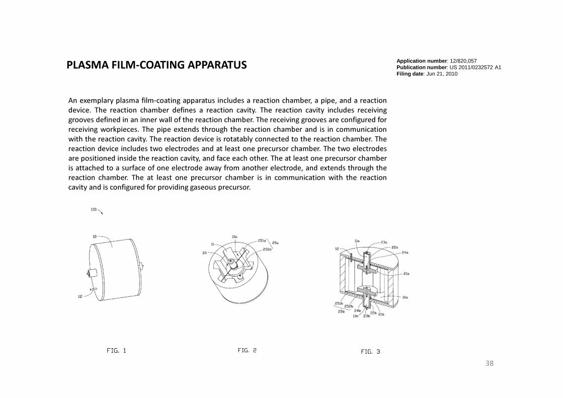
APPARATUS FOR PROCESSING COATING MATERIAL AND
EVAPORATION DEPOSITION DEVICE
An apparatus for processing coating material includes a crucible having a receptacle
for receiving coating material, a drive member having a drive shaft, a cover coupled
to the drive shaft, and a flame nozzle opposing the receptacle. The cover includes
an inner chamber, a first through hole and a number of second through holes. The
first through hole and the second through holes communicate with the inner chamber.
The cover has a flat surface with the second through holes exposed at the flat surface.
The drive shaft drives the cover to rotate between a closed position where the cover
covers the receptacle and the flat surface presses against the coating material to
flatten the coating material, and an open position where the cover is moved away
from the receptacle. The flame nozzle sprays flame from the second through holes
through the first through hole to heat the coating material.
US Patent
Application Document
57

POLISHING DEVICE
A polishing device includes an outer barrel, an inner barrel, polishing
members, and an actuator. The outer barrel defines a chamber and includes
inner surfaces substantially parallel to a central axis of the outer barrel. Each
of the inner surfaces defines a holding groove for holding a workpiece. The
inner barrel is received in the chamber and includes a side surface substantially
parallel to the central axis. The side surface defines installation grooves.
Each polishing member includes an elastic piece, a polishing motor connected to
a bottom of a corresponding installation groove by the elastic piece and received
in the corresponding installation groove, and a polishing plate connected to the
polishing motor and capable of being driven to rotate by the polishing motor.
The actuator is configured for driving the outer barrel to spin and move back and
forth along the central axis.
US Patent
Application Document
58

CYLINDRICAL GRINDING AND POLISHING DEVICE
A cylindrical grinding and polishing device includes a main body defining a cavity,
a polishing device, a cylindrical grinding device, a support device. The polishing device
is received in the cavity, and includes a number of polishing wheels positioned along a
first direction. The cylindrical grinding device is received in the cavity, and includes a
grinding wheel positioned at an end of the cavity along a second direction substantially
perpendicular to the first direction. The support device is received in the cavity, and
includes a support plate for supporting a work-piece. The support device carries the
work-piece to contact the polishing wheels or the grinding wheel.
US Patent
Application Document
59

A coating device includes a chamber, an evaporative source, a coating holder, and a
supporting structure. The evaporative source is positioned at the bottom of the chamber.
The coating holder is positioned at the top of the chamber and includes concentric
annular parts with different diameters, and drive devices connected to the annular parts
correspondingly. The drive devices are configured to move the annular parts along axial
directions of the annular parts. Each annular part includes a bottom board defining
receiving holes for receiving lenses. The supporting structure is positioned at the top of
the chamber and supports the drive devices.
COATING HOLDER AND COATING DEVICEUS Patent
Application Document
60

A sandblasting apparatus includes a chamber defining a cavity, a support assembly received in
the cavity, a first sandblasting assembly, and a second sandblasting assembly. The support assembly
includes a plurality of pairs of elongated support plates for holding a plate-shaped workpiece
therebetween. The support plates are moveable along a vertical direction and a first horizontal
direction. The first sandblasting assembly is configured for spraying sand downwardly toward the
plate-shaped workpiece so as to cut the plate-shaped workpiece into a plurality of workpiece stripes.
The second sandblasting assembly is configured for spaying sand toward the workpiece stripes along
a second horizontal direction perpendicular to the first horizontal direction so as to cut each of the
workpiece stripes into workpiece block, and processing the workpiece blocks into cylindrical
workpieces.
SANDBLASTING APPARATUS US Patent
Application Document
61

CRUCIBLE AND EVAPORATION DEPOSITION DEVICE
A crucible includes a body, an ejector and a drive member. The body has a
receptacle for receiving coating material, and a bottom in the receptacle. The
bottom has an ejector hole communicating with the receptacle. The ejector is
positioned below the receptacle and received in the ejector hole. The drive
member has a drive shaft coupled to the ejector. The drive member is configured
for driving the ejector to move toward or away from the receptacle along a central
axis of the ejector hole so that the coating material can be moved up or down in the
receptacle.
US Patent
Application Document
62

A sandblasting apparatus for cutting a plate-shaped workpiece into a plurality of separate tablets
includes a chamber defining a cavity, a support assembly received in the cavity, a sandblasting
assembly for spraying sand toward the workpiece, a first mask located between the sandblasting
assembly and the support assembly, a second mask located 5 between the sandblasting assembly and the
support assembly, and a mask switching member for selectively placing the first mask or the second
mask over the workpiece. The support assembly is configured for supporting the workpiece and the
tablets. The first mask cooperates with the sandblasting assembly to remove unwanted portions of
the workpiece thus obtaining a tablet network consisting of a plurality of tablets and a plurality of
10 connecting portions interconnected between the tablets. The second mask cooperates with the
sandblasting assembly to remove the connecting portions of the tablet network thus obtaining a
plurality of separated tablets.
SANDBLASTING APPARATUS US Patent
Application Document
63

COATING APPARATUS
A coating apparatus for coating a number of workpieces includes a deposition chamber, a
reaction assembly, and a controller. The reaction assembly is received in the deposition
chamber and includes an outer barrel, an inner barrel, a number of nozzles, and a number of
pipes. The housing and the outer barrel define a reaction chamber therebetween. The outer
barrel includes a main body and two protruding portions extending from the main body. The
workpieces are positioned on the protruding portions. The main body and the inner barrel
define a first room therebetween. The inner barrel defines a second room. The pipes
communicates the second room with the reaction chamber. The nozzles communicates the first
room with the reaction chamber. The controller controls the pipes to introduce a first reaction
gas to the first room or controls the nozzles to introduce a second reaction gas to the second
room in different time.
US Patent
Application Document
64

COATING DEVICE
A coating device includes a reaction device, a mixing device, a deposition device, a first
switching device and a second switching device. The reaction device defines a reaction
chamber. The mixing device is connected to the reaction device and defines a mixing
chamber that communicates with the reaction chamber. The deposition device is connected
to the mixing device and defines a deposition chamber that communicates with the mixing
chamber. The first switching device is configured to communicate and separate the reaction
chamber and the mixing chamber. The second switching device is configured to
communicate and isolate the mixing chamber and the deposition chamber.
US Patent
Application Document
65

A coating device includes a main body and at least one ionic-wind generating device.
The main body includes a first surface, a second surface opposite to the first surface, and
a plurality of receiving holes passing through the first surface and the second surface.
Each receiving hole is used for receiving an element which needs to be coated and
includes an inlet for letting the element to enter the receiving hole. The inlet is
positioned on the first surface. The at least one ionic-wind generating device is
positioned on one side of the main body, and is used for blowing ionic-wind towards a
direction opposite to the second surface, thus blowing ionic-wind towards the element
before the element enters the inlet.
COATING DEVICE
US Patent
Application Document
66
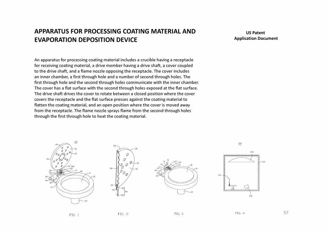
CUTTING DEVICE
An exemplary cutting device includes a support base, a first
slide module, a second slide module slidably connected to the first
slide module, and a cutting module. The support base includes a
support surface and a first slide portion on the support surface. The
cutting module includes a fixed frame fixed on the second slide
module, a driving device fixed on the fixed frame, and a cutter
connected to the driving device. The driving device drives the
cutter to rotate and move up and down along its own axis. The
cutter includes a hollow cylindrical blade which can create round
glass lenses of predetermined dimensions without the need to firstly
secure the glass blank by adhesive or similar means.
US Patent
Application Document
67

A loading device which is used in coating processes includes a base, a loading plate,
and a reversing assembly. The base includes an outer frame and a ring-shaped inner
frame rotatably positioned on the outer frame. The loading plate defines a number of
holes for loading components. The reversing assembly connects the inner frame to the
loading plate. The reversing assembly includes two reversing motors and two shafts.
The reversing motors are opposite to each other and fixed on the inner frame. The
reversing shafts are opposite to each other and positioned in a straight line. One end of
each reversing shaft is coupled with a corresponding reversing motor, the other end of
each reversing shaft is fixed on the loading plate. The reversing shafts are driven by the
reversing motors to reverse the loading plate relative to the inner frame.
LOADING DEVICE FOR COATING PROCESSUS Patent
Application Document
68

CLEANING DEVICE
A cleaning device for cleaning a holder includes a support component and a
jetting component. The support component fixes the holder. The jetting
component jets high pressure water into the holder to clean the holder.
US Patent
Application Document
69

EVAPORATION SOURCE WITH FLAME JETTING UNIT AND
RELATED EVAPORATION DEPOSITION SYSTEM
An evaporation source includes a crucible chamber, a crucible, a driving unit, a
flame jetting unit and an electron-beam emitting unit. The crucible is rotatably received
in the crucible chamber, and contains a target material. The driving unit is located on a
sidewall of the crucible chamber and drives the crucible to rotate. The flame jetting unit
jets a flame to pre-heat the target material in the crucible. The electron-beam emitting
unit emits an electron-beam to the crucible to evaporate the pre-heated target material.
An evaporation deposition system using the evaporation source is also provided.
US Patent
Application Document
70

Research Experience (I)
-- Color Filter Development
71

traditional IR cut filter hybrid IR cut filter
In order to improve image quality, our team use coating technique on glass for IR-Cut thin film deposition.
It always cut light wavelength from 700~1100 nm due to prevent red light pass through image sensor. Light in red will
cause image sensor be sensitive and flare on camera screen will break down the photos quality.
We had already completed mass production in Foxconn, China. The component used for camera module of popular i-phone communication device has been proved from world’s A customers .
But there are a few problems still be modified until going to the new i-phone generation. The problem here means “petal flare”. It can be solved by “hybrid IR Cut filter”.
Here are some photos about IR-Cut filter and explanation about how we improve the “petal flare”.
traditional IR cut filter hybrid IR cut filter
petal flare no red petal flare
Image quality can be investigated by using each hands-on light source simulation including fluorescent lamp
test , artificial sunlight test, halogen lamp test, tungsten halogen lamp test, stray light test, studio image test,
relative illumination test, and color shading test to check flare and color shading effect on camera module.
halogen lamp testhalogen sun light testfluorescent lamp test tungsten halogen lamp test
stray light test studio image test
72

In today modern society, people always love to take a picture outside with high resolution image camera device in order to satisfy their desire. Based on the condition, there are some kind of new
technologies performing now. The name is called wafer level optics (WLO). The camera modules of the portable electronic devices have become smaller and smaller in size. Accordingly, it is required
that optical elements (e.g., a light blocking plate) used in the camera module have a smaller size/volume.
Due to WLO expensive cost, and complex manufacturing process. These reasons cause WLO can’t expand quickly to the world’s market. So we need to think about a better solution to solve the
mentioned problems.
This is an example of the process solution, related patents had been issued: LIGHT BLOCKING PLATE, CAMERA MODULE HAVING SAME, AND METHOD FOR MAKING SAME, US8009980 (Issue date Aug
30, 2011), the patent shows the solution of making the light blocking plate by semiconductor process. Detail technology can see on google patents or refer to next patent detail introductory.
Traditional Camera Module Structure
holder
barrel
lens
sensorIR-CUT
Foxconn Corp. is professional electronic manufacturing company to produce electronic device from prototype design in real ones. The business model we were said is OEM/ODM which vendor can corporate with
customer site for their demands. In below electronic components, camera module, has been used in i-phone portable device for many years but it has still been more difficult issues to overcome. So we need to
develop it in effort to put scale of patent applications first under many ideals and technologies before manufacturing. I had already invented lots of process patents, please check detail on google patents or refer
to next patent detail introductory.
Wafer Level Optics (WLO)
WLO
camera module die attached on the sensor
73

Research Experience (II)
-- Sensor Development
74

This material fabricated by ZnO nanorod. The variety shape can let sensor detect gas more sensitive.
Our team has been developed variety shapes by controlling different process time and temperature.
We also developed 3D axis nano structure to detect gas molecule. The rod has 30nm diameter, 2um rod length,
and has more complex vacancy on rod surface.
Rod shape can detect strong sensing signal, It can be used in variety technical field in
house fire detector, commercial electronic parts, and so on.
In those tech combination, I invent a kind of brush using ZnO nanorod material for the concept design
Each brush hair has connected into signal sensor to monitor the younger or older person could be careful of their teeth.
If they don’t clean their teeth cleaning, sensor will detect it from smelling and mouth cavity environment and feedback
information to the user. We developed it successfully and applied patents. We hope to share everyone this great invention
and open it to the world’s market.
Brush hair (ZnO material)
sensor
alarm system
ZnO nanorod gas sensor for NO2 detectionFang-Tso Liu, Shiang-Fu Gao, Shao-Kai Pei, Shih-Cheng Tseng, Chin-Hsin J. Liu *
Department of Chemical Engineering, National Taiwan University of Science and Technology, Taipei 106, Taiwan
75

Nanostructured IrO2 crystals are grown on a gold-coated quartz substrate by metal organic chemical vapor deposition (MOCVD).
The resultant quartz crystal microbalance (QCM) sensors show good gas sensitivities towards carboxylic acid at the ppm level.
When the oxide is heated at 450℃~600℃in high vaccum, the IrO2 is partially reduced to Ir/IrO2 by thermal decomposition.
The Ir/IrO2 sensor shows higher gas sensitivity as compared to the IrO2 sensor, but with lower sensor reversibility.
Further improvement of the sensor reversibility can be achieved by growing the IrO2 crystals onto a thin Ti layer deposited on the Au electrode,
followed by the same reduction treatment.
The composition and the morphology of the IrO2 surface before and after thermal reduction are investigated by X-ray diffraction (XRD),
X-ray photoelectron spectroscopy (XPS), Raman spectroscopy, and scanning electron microscopy (SEM).
The mechanism of improvements in sensitivity and reversibility will also be discussed.
MOCVD system VOC sensing system
0 1000 2000 3000 4000 5000 6000 7000 80009926360
9926380
9926400
9926420
9926440
9926460
9926480
9926500
9926520
9926540
9926560
9926580
600ppm
400ppm200ppm
100ppm
50ppm
10ppm
5ppm
Freq
uen
cy (
Hz)
Time (s)
Ts=350 oC Tr=550 oC tr=30 min
1ppm
This research used AT-cut 10MHz quartz covered by two side of gold electrode which was 0.38 cm diameter and MOCVD method, syatem as shown in Fig. to deposit IrO2 nano rod onto gold electrode surface.
Precursor coated material was (MeCp)Ir(COD) under 110℃ to mixed well and spray onto the QCM substrate. Substrate temperature(Ts) was controlled in 350℃ and environmental gas flow was 80 sccm under the
maintained chamber pressure for 20 mbar. After deposited IrO2 for 1 hr, we opened turbo pump to further reached in high vacccum pressure at 5*10-5mbar and controlled Ts from 350℃ up to the range
of 450℃ ~ 600℃ for 30 to 90 minutes. Finally, compared the above sensor result before and after reduction.
When did upon work of manufactured IrO2-OCM electrode, we used VOC sensing system, to detect sensor signal by injected Propanic acid compound to volatile acid gas adsorption
on IrO2-QCM surface. After a while when adsorped signal frequency was stable and was no variation increased, then controlled nitrogen gas by MFC flow meter to 100 sccm at 25℃ and desorption acid molecule
from IrO2 surface.
Figure shows that XPS analyze IrO2 composition before and after reduction at different reduction temperature. When the
reduction temperature headed up to 450℃which composition consisted of IrO2/IrO3/Ir(OH)x was as the same as no reduction, as shown in
Fig (a)(b), but fewer binding peak of Ir 4f7/2
and Ir4f5/2
at 450℃ than no reduction. It was probably the reason that no increased variation
frequency but decreased reversibility. When headed up to 550℃, the phase transformed to Ir/IrO2 and its higherΔf (~270Hz) and Re%(~98%)
contributed to the C=O or –OH easily to bind with Ir vacancy side by physical adsorption to form the byproduct IrO2. After pump in N2 gas to
desorption, reversibility will easily to recover. When headed up to 600℃, the phase transformed to Ir/Ir4+-Oads and Δf further up to 320Hz .
However reversibility goes down to 32%. The reason for that contributed to the C=O or –OH much strongly binding on metal Ir but hardly to
leave from Ir4+-Oads, Oads may be hydroxide from the air.
Quartz crystal microbalance sensor based on partially reduced IrO2S.K. Pei a, C.J. Liu a,*, Y.S. Huang b, D.S. Tsai a
a Department of Chemical Engineering, National Taiwan University of Science and Technology
b Department of Electronic Engineering, National Taiwan University of Science and Technology
76

SEM top view and cross sectional view under the different reduction time and reduction temperature.
The surface morphology before reduction shows incomplete-nanotube and nano blade as the same as by controlling lower
reduction temperature 450℃. At higher reduction temperature like 550℃, nanorod were aggregated to form the flower shape
which existed much more adsoption area that caused higher variarition frequency. Nanorode length which was easily increased by
higher reduction temperature, but there is no evidence to say the length could affect the sensor quality.
0 30 60 900
50
100
150
200
250
300
350
400 (a)
delt
a fr
equ
ency
, ∆∆ ∆∆f (
Hz)
reduction time (min)
reduction at 450 oC reduction at 500 oC reduction at 550 oC reduction at 600 oC
0 30 60 900
20
40
60
80
100(b)
reduction time (sec)
450 oC 500 oC 550 oC 600 oC
reve
rsib
ility
, Re
%
Iridium dioxide can be produced by MOCVD and partially reduced at different reduction temperature and reduction time.
We proved the adsorption frequency and revesibility coming from oxgen vacancy on Iridium metal such as Ir/Ir4+ vacancy,
Ir4+ vacancy or Ir vacancy. We also improved reversibility by coated Ti seed layer under IrO2 nanorod. It was very efficiency
way that could be used in all kind of metal oxide gas sensor.
X-ray diffraction pattern shows that only IrO2 peak existed in the structure. After the reduction for 450~550℃, the main IrO2 (101) was partial reduced to Ir/IrO2 phase.
30 40 50 60 70 80
Ir(2
00)
IrO
2 (22
0)
IrO
2 (2
11)
IrO
2 (11
0)
Ir(1
11)Ir
O2 (
101) A
u (
111)
before reduction
reduction at 550 oC
reduction at 500 o
C
reduction at 450 o
C
2θθθθ
In
ten
sity
(a.
u)
Quartz crystal microbalance sensor based on partially reduced IrO2S.K. Pei a, C.J. Liu a,*, Y.S. Huang b, D.S. Tsai a
a Department of Chemical Engineering, National Taiwan University of Science and Technology
b Department of Electronic Engineering, National Taiwan University of Science and Technology
77

Statement of Purpose
My name is SHAO-KAI PEI. I was greatly inspired by media-lab speakers from Ted.com and opening course for turning their innovative ideasinto actual inventions. Hence I have been applying my enthusiasm for inventions ever since. I have been focusing on improving theOEM/ODM electronic manufacturing as well as the R&D strength with Foxconn Technology Group, the company I am working now, and Ihave filed 105 U.S. patents with 13 patents issued with the company. In addition, I had managerial experience over product design andmanufacturing for clients such as Apple, Nokia, HTC, and Nintendo.
During the past 2 year of the world’s economic crisis, we met a lot of factory problems not only a labor strike on salary but also the productsprofit going down. Overseeing the obstacles and failures Foxconn encountered in the past, I believe high profit products should be in what thecompany gear for. Apple Inc. is an excellent example benefiting from highly attractive product lines. Hence I will be studying in developing onhighly desirable products with durable hardware, software and the industrial surface design.
In the past six years, I also learn lots of research skills at Foxconnand VIS semiconductor company on studying thin film design andmanufacturing including inorganic film, organic film or optical film used on sensor, solar cell, semiconductor, camera module, optical device orplastic/glass decoration. I was familar with several deposition systems at the same time. Previously, when I was a 1st year graduated student, Iinvented a new kind of spray pyrolysis system which used a few solvent to do thesame thing as market spray system. My invented-system onlycost 300 USD dollars was cheaper than 5,000 USD market system. Finally, I connected my system with hydrothermal system to deposit wellstable nanorod. The achievements had already been published in the journaland national conference papers. Based on this system, it alsohelped many junior students in the laboratory to graduate soon. It made me feel sofulfillment and happy for helping people finish on theirworks. In my 2nd year, Professor asked me doing the most important National Science Council project with other laboratory students. Undertime restriction, I figured out using MOCVD to deposit IrO2-Oxygen vacancy nanorod under high temperature annealing treatment on QCMsensor and discover higher sensitive signals on sensing Propanic/Amino acid than traditional IrO2 sensor. It will probably improve PH meterfunction in the future. Therefore, when I graduated from school, I got 89(A) score ofmy oral thesis.
I believe that my professional coating experience can help Professorto develop new kind of materials both in creative ways and in cost-downsolution combined with some coating treatments of high-quality thin film deposition. I am certain that study will help me to fulfill of myresearch goals of inventing under profit into the world’s market. Hope you can take my application into consideration and give me a chance torealize my dream to become outstanding inventor in the world.