Embed Size (px)
Citation preview
SScchhrruupppp HHyyddrraauulliicc
AAccccuummuullaattoorrss


HL Hydraulic, Inc. P.O. Box 450 • Seneca, PA 16346 • Phone 814-677-4086 • Toll Free 877-677-4086 • Fax 814-677-
4087 Website: www.hlhydraulic.com • E-mail: [email protected]
3
TABLE OF CONTENTS DESCRIPTION SPECIFICATION NO. PAGE NO.Standard Bladder Accumulators, 3000 psi ABA-001 4
Standard Bladder Accumulators, 5000 psi ABA-002 5
Top Repairable Bladder Accumulators, 3000 psi ABA-003 6
Top Repairable Bladder Accumulators, 5000 psi ABA-004 7
Transfer Barrier Bladder Accumulators, 3000 psi ABA-001---T 8
Bladder Accumulator Gas Bottles, 3000 psi ABA-001---G 9
Bladder Accumulator Accessories 10
Bladder Accumulator Mounting Brackets 11
Replacement Bladders & Optional Fluid Ports 12
Bladder Accumulators Ordering Information 13
Bladder Accumulator Maintenance Instructions 14-16
Bladder Accumulator, Top Repairable, Welded Construction ADA-HTR 17
Diaphragm Accumulator Welded Construction ADA-H 18
Diaphragm Accumulator Threaded Construction ADA-HST 19
Diaphragm Accumulator, PVC or Polypropylene Body
ADA-HSTPVC ADA-HSTP 20
Diaphragm Accumulator, Stainless Steel Body ADA-HSTX 21
Diaphragm Accumulator, Charging Assembly & Gas Valve
SCA-160 SCA-162 22
Bladder Type Pulsation Dampeners HBX 23
Bladder Type Pulsation Dampeners, Top Repairable
HTRX BXT 24
Accumulator Special Executions 25

HL Hydraulic, Inc. P.O. Box 450 • Seneca, PA 16346 • Phone 814-677-4086 • Toll Free 877-677-4086 • Fax 814-677-
4087 Website: www.hlhydraulic.com • E-mail: [email protected]
4
BLADDER ACCUMULATORS
Specification No. ABA-001
ASME VIII Range 3000 psi
TECHNICAL
Maximum Working Pressure: 3000 psi @ 200°F Minimum Test Pressure: 4500 psi Nominal Capacities: 1quart, 1.0, 2.5, 5.0, 10.0 & 15.0 gal.
DESIGN
Shell: Designed and Manufactured in accordance with ASME Code Rules, Section VIII, Division 1 Material - Chrome Molybdenum Steel, SA372 Grade E, Class 70 (Meets 4 : 1 Safety Requirements)
Separator Bag: Totally enclosed molded synthetic rubber bag in a range of materials. Integral steel stem fitted with gas valve assembly, sealing cap, O-ring, locknut and protective cap.
Fluid Port Assembly: Poppet type assembly manufactured in AISI 4130 carbon steel specifications, complete with molded retaining rings, locking ring and bleed plug.
Inspection: Shell certified throughout manufacture with witness testing by independent authorities, ASME approval and “U” code stamped.
Finish: One coat epoxy based primer. Special finishes available.
Dimensions, inch (mm) Hydraulic Ports Nominal Capacity Gallons (Liters)
Gas Volume Cu. in. (Liters)
Max. WP psi
(bar)
Weight
Lbs. (kg) A B C D E F G H Size¹
(Thread) J Size
(Thread) 1 Qt. (0.95)
60 (0.95)
3000² (207)
10 (4.5)
4.50 (114)
11.25 (286)
1.75 (45)
2.00 (51)
1.75 (45)
2.50 (63.5)
1.00 (25.4)
SAE #16 (1-5/16”-12) N/A
1.0 (3.79)
231 (3.79)
3000 (207)
30 (13.3)
6.75 (171)
16.25 (413)
2.25 (58)
2.75 (70)
2.36 (59.9)
3.13 (79.5)
1.00 (25.4)
SAE #20 (1-5/8”-12)
SAE #6 (9/16”-18)
2.5 (9.46)
600 (9.8)
3000 (207)
80 (36)
9.00 (230)
21.25 (540)
2.25 (58)
3.50 (89)
3.00 (76.2)
4.13 (105)
1.00 (25.4)
SAE #24 (1-7/8”-12)
SAE #6 (9/16”-18)
5.0 (18.9)
1203 (19.7)
3000 (207)
120 (55)
9.00 (230)
33.50 (851)
2.25 (58)
3.50 (89)
3.00 (76.2)
4.13 (105)
1.00 (25.4)
SAE #24 (1-7/8”-12)
SAE #6 (9/16”-18)
10.0 (37.9)
2259 (37.0)
3000 (207)
220 (100)
9.00 (230)
54.50 (1384)
2.25 (58)
3.50 (89)
3.00 (76.2)
4.13 (105)
1.00 (25.4)
SAE #24 (1-7/8”-12)
SAE #6 (9/16”-18)
15.0 (56.8)
3440 (56.3)
3000 (207)
300 (133)
9.00 (230)
78.00 (1981)
2.25 (58)
3.50 (89)
3.00 (76.2)
4.13 (105)
1.00 (25.4)
SAE #24 (1-7/8”-12)
SAE #6 (9/16”-18)
All dimensions subject to change without notice ¹ Optional Fluid Ports Available. ² In accordance with ASME VIII calculations only.
2.5 – 15 Gallon Split Flange Fluid Port Option

HL Hydraulic, Inc. P.O. Box 450 • Seneca, PA 16346 • Phone 814-677-4086 • Toll Free 877-677-4086 • Fax 814-677-
4087 Website: www.hlhydraulic.com • E-mail: [email protected] 5
BLADDER ACCUMULATORS
Specification No. ABA-002
ASME VIII Range 5000 psi
TECHNICAL
Maximum Working Pressure: 5000 psi @ 200°F Minimum Test Pressure: 7500 psi Nominal Capacities: 2.5, 5.0, 10.0 & 15.0 gal.
DESIGN
Shell: Designed and Manufactured in accordance with ASME Code Rules, Section VIII, Division 1 Material - Chrome Molybdenum Steel, SA372 Grade E Class 70 (Meets 4 : 1 Safety Requirements)
Separator Bag: Totally enclosed molded synthetic rubber bag in a range of materials. Integral steel stem fitted with gas valve assembly, sealing cap, O-ring, locknut and protective cap.
Fluid Port Assembly: Poppet type assembly manufactured in AISI 4130 carbon steel specifications, complete with molded retaining rings, locking ring and bleed plug.
Inspection: Shell certified throughout manufacture with witness testing by independent authorities, ASME approval and “U” code stamped.
Finish: One coat epoxy based primer. Special finishes available.
Dimensions, inch (mm) Hydraulic Ports Nominal Capacity Gallons (Liters)
Gas Volume Cu. in. (Liters)
Max. WP psi
(bar)
Weight
Lbs. (kg) A B C D E F G
Hex. H Size¹
(Thread) J Size
(Thread) 2.5
(9.46) 600 (9.8)
5000 (345)
125 (57)
9.75 (248)
24.00 (610)
3.25 (83)
4.00 (102)
3.00 (76.2)
4.00 (102)
2.50 (63.5)
SAE #24 (1-7/8”-12)
SAE #6 (9/16”-18)
5.0 (18.9)
1203 (19.7)
5000 (345)
200 (91)
9.75 (248)
36.00 (914)
3.25 (83)
4.00 (102)
3.00 (76.2)
4.00 (102)
2.50 (63.5)
SAE #24 (1-7/8”-12)
SAE #6 (9/16”-18)
10.0 (37.9)
2259 (37.0)
5000 (345)
350 (159)
9.75 (248)
57.00 (1448)
3.25 (83)
4.00 (102)
3.00 (76.2)
4.00 (102)
2.50 (63.5)
SAE #24 (1-7/8”-12)
SAE #6 (9/16”-18)
15.0 (56.8)
3440 (56.3)
5000 (345)
500 (227)
9.75 (248)
80.00 (2032)
3.25 (83)
4.00 (102)
3.00 (76.2)
4.00 (102)
2.50 (63.5)
SAE #24 (1-7/8”-12)
SAE #6 (9/16”-18)
All dimensions subject to change without notice ¹ Optional Fluid Ports Available.

HL Hydraulic, Inc. P.O. Box 450 • Seneca, PA 16346 • Phone 814-677-4086 • Toll Free 877-677-4086 • Fax 814-677-
4087 Website: www.hlhydraulic.com • E-mail: [email protected]
6
BLADDER ACCUMULATORS
Specification No. ABA-003
ASME VIII Range (Top Repairable) 3000 psi
TECHNICAL
Maximum Working Pressure: 3000 psi @ 200°F Minimum Test Pressure: 4500 psi Nominal Capacities: 2.5, 5.0, 10.0 & 15.0 gal.
DESIGN
Shell: Designed and Manufactured in accordance with ASME Code Rules, Section VIII, Division 1 Material - Chrome Molybdenum Steel, SA372 Grade E Class 70 (Meets 4 : 1 Safety Requirements)
Separator Bag: Totally enclosed molded synthetic rubber bag in a range of materials. Integral steel stem fitted with gas valve assembly, sealing cap, O-ring, locknut and protective cap.
Fluid Port Assembly: Poppet type assembly manufactured in AISI 4130 carbon steel specifications, complete with molded retaining rings, locking ring and bleed plug.
Inspection: Shell certified throughout manufacture with witness testing by independent authorities, ASME approval and “U” code stamped.
Finish: One coat epoxy based primer. Special finishes available.
Dimensions, inch (mm) Hydraulic Ports Nominal Capacity Gallons (Liters)
Gas Volume Cu. in. (Liters)
Max. WP psi
(bar)
Weight
Lbs. (kg) A B C D E F G H Size¹
(Thread) J Size
(Thread) 2.5
(9.46) 600 (9.8)
3000 (207)
80 (36)
9.00 (230)
21.25 (540)
1.75 (45)
3.50 (89)
3.00 (76.2)
4.13 (105)
3.00 (76.2)
SAE #24 (1-7/8”-12)
SAE #6 (9/16”-18)
5.0 (18.9)
1203 (19.7)
3000 (207)
120 (55)
9.00 (230)
33.50 (851)
1.75 (45)
3.50 (89)
3.00 (76.2)
4.13 (105)
3.00 (76.2)
SAE #24 (1-7/8”-12)
SAE #6 (9/16”-18)
10.0 (37.9)
2259 (37.0)
3000 (207)
220 (100)
9.00 (230)
54.50 (1384)
1.75 (45)
3.50 (89)
3.00 (76.2)
4.13 (105)
3.00 (76.2)
SAE #24 (1-7/8”-12)
SAE #6 (9/16”-18)
15.0 (56.8)
3440 (56.3)
3000 (207)
300 (133)
9.00 (230)
78.00 (1981)
1.75 (45)
3.50 (89)
3.00 (76.2)
4.13 (105)
3.00 (76.2)
SAE #24 (1-7/8”-12)
SAE #6 (9/16”-18)
All dimensions subject to change without notice ¹ Optional Fluid Ports Available.

HL Hydraulic, Inc. P.O. Box 450 • Seneca, PA 16346 • Phone 814-677-4086 • Toll Free 877-677-4086 • Fax 814-677-
4087 Website: www.hlhydraulic.com • E-mail: [email protected] 7
BLADDER ACCUMULATORS
Specification No. ABA-004
ASME VIII Range (Top Repairable) 5000 psi
TECHNICAL
Maximum Working Pressure: 5000 psi @ 200°F Minimum Test Pressure: 7500 psi Nominal Capacities: 2.5, 5.0, 10.0 & 15.0 gal.
DESIGN
Shell: Designed and Manufactured in accordance with ASME Code Rules, Section VIII, Division 1 Material - Chrome Molybdenum Steel, SA372 Grade E Class 70 (Meets 4 : 1 Safety Requirements)
Separator Bag: Totally enclosed molded synthetic rubber bag in a range of materials. Integral steel stem fitted with gas valve assembly, sealing cap, O-ring, locknut and protective cap.
Fluid Port Assembly: Poppet type assembly manufactured in AISI 4130 carbon steel specifications, complete with molded retaining rings, locking ring and bleed plug.
Inspection: Shell certified throughout manufacture with witness testing by independent authorities, ASME approval and “U” code stamped.
Finish: One coat epoxy based primer. Special finishes available.
Dimensions, inch (mm) Hydraulic Ports Nominal Capacity Gallons (Liters)
Gas Volume Cu. in. (Liters)
Max. WP psi
(bar)
Weight
Lbs. (kg) A B C D E F G
Hex. H Size¹
(Thread) J Size
(Thread) 2.5
(9.46) 600 (9.8)
5000 (345)
125 (57)
9.75 (248)
24.00 (610)
3.25 (83)
4.00 (102)
3.00 (76.2)
4.00 (102)
2.50 (63.5)
SAE #24 (1-7/8”-12)
SAE #6 (9/16”-18)
5.0 (18.9)
1203 (19.7)
5000 (345)
200 (91)
9.75 (248)
36.00 (914)
3.25 (83)
4.00 (102)
3.00 (76.2)
4.00 (102)
2.50 (63.5)
SAE #24 (1-7/8”-12)
SAE #6 (9/16”-18)
10.0 (37.9)
2259 (37.0)
5000 (345)
350 (159)
9.75 (248)
57.00 (1448)
3.25 (83)
4.00 (102)
3.00 (76.2)
4.00 (102)
2.50 (63.5)
SAE #24 (1-7/8”-12)
SAE #6 (9/16”-18)
15.0 (56.8)
3440 (56.3)
5000 (345)
500 (227)
9.75 (248)
80.00 (2032)
3.25 (83)
4.00 (102)
3.00 (76.2)
4.00 (102)
2.50 (63.5)
SAE #24 (1-7/8”-12)
SAE #6 (9/16”-18)
All dimensions subject to change without notice ¹ Optional Fluid Ports Available.
A
B
HEF
J
C
G
D

HL Hydraulic, Inc. P.O. Box 450 • Seneca, PA 16346 • Phone 814-677-4086 • Toll Free 877-677-4086 • Fax 814-677-
4087 Website: www.hlhydraulic.com • E-mail: [email protected]
8
BLADDER ACCUMULATORS
Specification No. ABA-001- - -T
Transfer Barriers
ASME VIII Range 3000 psi
TECHNICAL
Maximum Working Pressure: 3000 psi @ 200°F Minimum Test Pressure: 4500 psi Nominal Capacities: 2.5, 5.0, 10.0 & 15.0 gal.
DESIGN
Shell: Designed and Manufactured in accordance with ASME Code Rules, Section VIII, Division 1 Material - Chrome Molybdenum Steel, SA372 Grade E, Class 70 (Meets 4 : 1 Safety Requirements)
Separator Bag: Totally enclosed molded synthetic rubber bag in a range of materials. Integral steel stem fitted with gas tube, O-ring seals, locknut and gas tube adapter nut.
Fluid Port Assembly: Poppet type assembly manufactured in AISI 4130 carbon steel specifications, complete with molded retaining rings, locking ring and bleed plug.
Inspection: Shell certified throughout manufacture with witness testing by independent authorities, ASME approval and “U” code stamped.
Finish: One coat epoxy based primer. Special finishes available.
Dimensions, inch (mm) Hydraulic Ports Nominal Capacity Gallons (Liters)
Gas Volume Cu. in. (Liters)
Max. WP psi
(bar)
Weight
Lbs. (kg) A B C D E F G
Hex. H Size¹
(Thread) J Size
(Thread) 2.5
(9.46) 600 (9.8)
3000 (207)
80 (36)
9.00 (230)
21.75 (553)
2.75 (70)
3.50 (89)
3.00 (76.2)
4.13 (105)
1.25 (31.8)
SAE #24 (1-7/8”-12)
SAE #6 (9/16”-18)
5.0 (18.9)
1203 (19.7)
3000 (207)
120 (55)
9.00 (230)
34.00 (864)
2.75 (70)
3.50 (89)
3.00 (76.2)
4.13 (105)
1.25 (31.8)
SAE #24 (1-7/8”-12)
SAE #6 (9/16”-18)
10.0 (37.9)
2259 (37.0)
3000 (207)
220 (100)
9.00 (230)
55.00 (1397)
2.75 (70)
3.50 (89)
3.00 (76.2)
4.13 (105)
1.25 (31.8)
SAE #24 (1-7/8”-12)
SAE #6 (9/16”-18)
15.0 (56.8)
3440 (56.3)
3000 (207)
300 (133)
9.00 (230)
78.50 (1994)
2.75 (70)
3.50 (89)
3.00 (76.2)
4.13 (105)
1.25 (31.8)
SAE #24 (1-7/8”-12)
SAE #6 (9/16”-18)
All dimensions subject to change without notice ¹ Optional Fluid Ports Available.

HL Hydraulic, Inc. P.O. Box 450 • Seneca, PA 16346 • Phone 814-677-4086 • Toll Free 877-677-4086 • Fax 814-677-
4087 Website: www.hlhydraulic.com • E-mail: [email protected] 9
BLADDER ACCUMULATORS
Specification No. ABA-001- - - G
Gas Bottles
ASME VIII Range 3000 psi
TECHNICAL
Maximum Working Pressure: 3000 psi @ 200°F Minimum Test Pressure: 4500 psi Nominal Capacities: 2.5, 5.0, 10.0 & 15.0 gal.
DESIGN
Shell: Designed and Manufactured in accordance with ASME Code Rules, Section VIII, Division 1 Material - Chrome Molybdenum Steel, SA372 Grade E, Class 70 (Meets 4 : 1 Safety Requirements)
Fluid Port Assembly: Assembly manufactured in AISI 4130 carbon steel specifications, complete with molded retaining rings, locking ring and bleed plug.
Drain Port Assembly: Molded Buna-N sealing adapter. Integral steel stem fitted with locknut and drain plug.
Inspection: Shell certified throughout manufacture with witness testing by independent authorities, ASME approval and “U” code stamped.
Finish: One coat epoxy based primer. Special finishes available.
Dimensions, inch (mm) Ports Nominal Capacity Gallons (Liters)
Gas Volume Cu. in. (Liters)
Max. WP
psi (bar)
Weight
Lbs. (kg) A B C D E F G H Size¹
(Thread) J Size
(Thread) K Size
(Thread) 2.5
(9.46) 600 (9.8)
3000 (207)
80 (36)
9.00 (230)
20.38 (518)
0.88 (22)
3.50 (89)
3.00 (76.2)
4.13 (105)
0.88 (22)
SAE #24 (1-7/8”-12)
SAE #6 (9/16”-18)
SAE #3 (3/8”-24)
5.0 (18.9)
1203 (19.7)
3000 (207)
120 (55)
9.00 (230)
32.63 (829)
0.88 (22)
3.50 (89)
3.00 (76.2)
4.13 (105)
0.88 (22)
SAE #24 (1-7/8”-12)
SAE #6 (9/16”-18)
SAE #3 (3/8”-24)
10.0 (37.9)
2259 (37.0)
3000 (207)
220 (100)
9.00 (230)
53.63 (1362)
0.88 (22)
3.50 (89)
3.00 (76.2)
4.13 (105)
0.88 (22)
SAE #24 (1-7/8”-12)
SAE #6 (9/16”-18)
SAE #3 (3/8”-24)
15.0 (56.8)
3440 (56.3)
3000 (207)
300 (133)
9.00 (230)
77.13 (1959)
0.88 (22)
3.50 (89)
3.00 (76.2)
4.13 (105)
0.88 (22)
SAE #24 (1-7/8”-12)
SAE #6 (9/16”-18)
SAE #3 (3/8”-24)
All dimensions subject to change without notice ¹ Optional Fluid Ports Available.

HL Hydraulic, Inc. P.O. Box 450 • Seneca, PA 16346 • Phone 814-677-4086 • Toll Free 877-677-4086 • Fax 814-677-
4087 Website: www.hlhydraulic.com • E-mail: [email protected]
10
BLADDER ACCUMULATORS
Accessories
Available from Schrupp
SCA-313 Charging & Gauging Head Assembly
SCA-31 3,000 psi Pressure Gauge SCA-49 2,000 psi Pressure Gauge SCA-51 5,000 psi Pressure Gauge
SCA-53 1-15 Gallon Valve Stem SCA-52 5,000 psi Gas Valve SCA-47 Valve Stem Extension
SBP Bag Puller Rod SCH-CT Valve Core Cross Type Tool SCH-SW Spanner Wrench SCA-3 Complete 3,000 psi Charging Assembly
SCA-44 Hose Assembly
SCA-314 Head Assembly

HL Hydraulic, Inc. P.O. Box 450 • Seneca, PA 16346 • Phone 814-677-4086 • Toll Free 877-677-4086 • Fax 814-677-
4087 Website: www.hlhydraulic.com • E-mail: [email protected] 11
BLADDER ACCUMULATORS
Mounting Brackets for Accumulators Designed for specific use on Accumulator installation, both Clamps & Bases are supplied complete with Rubber Support to ensure rigid mounting.
ACCUMULATOR BRACKETS MODEL A
In. (mm) B In. (mm)
C In. (mm)
D (DIA.) In. (mm)
H In. (mm)
K In. (mm)
L (Slot) In. (mm)
WIDTH In. (mm)
SCH- 1 QRT
5.26 (134)
3.94 (100)
6.68 (170)
4.51 (115) 2.87 (73) --- 0.35 x 0.50 (8.9 x 12.7) 1.25 (32)
SCH- 1 GAL
7.50 (191)
6.02 (153)
9.00 (229)
6.75 (171)
3.94 (100) --- 0.35 x 0.50 (8.9 x 12.7) 1.25 (32)
SCH-2.5-15 GAL
10.0 (254)
8.50 (216)
9.67 (246)
8.90 (226)
4.84 (123)
12.5 (317) 0.59 (15) 1.58 (40)
BASE BRACKETS WITH RUBBER RINGS MODEL A
In. (mm) B In. (mm)
C In. (mm)
D (DIA.) In. (mm)
E In. (mm)
F In. (mm)
G In. (mm)
H In. (mm)
L (DIA.) In. (mm)
SB- 1 GAL
10.2 (260)
7.87 (200)
3.94 (100)
4.72 (120) 2.95 (75) 1.38 (35) 8.86
(225) 3.94 (100) 0.67 (17)
SB-2.5- 15 GAL
10.2 (260)
7.87 (200)
3.94 (100)
6.69 (170) 2.95 (75) 1.38 (35) 8.86
(225) 4.84 (123) 0.67 (17)
RUBBER RINGS MODEL A
In. (mm) B In. (mm)
C In. (mm)
D (DIA.) In. (mm)
E In. (mm)
F In. (mm) USE WITH BASE BRACKET NO.
SCA-138 5.91 (150)
4.72 (120)
4.69 (119)
4.25 (108) 0.79 (20) 0.59 (15) SB-1 GAL
SCA-139 7.87 (200)
6.69 (170)
6.65 (169)
6.26 (159) 0.79 (20) 0.59 (15) SB-2.5 GAL – 15 GAL
All dimensions subject to change without notice
RUBBER RINGSBASE BRACKETS
ACCUMULATOR BRACKETS
1 QRT. – 1 GAL.
2½ GAL. – 15 GAL.

HL Hydraulic, Inc. P.O. Box 450 • Seneca, PA 16346 • Phone 814-677-4086 • Toll Free 877-677-4086 • Fax 814-677-
4087 Website: www.hlhydraulic.com • E-mail: [email protected]
12
BLADDER ACCUMULATORS
Replacement Bladders 3000 PSI BLADDER KITS
Bladder Material & Part No. Size Buna-N Butyl EPR Viton Low Temp.1 Quart ABA-001-B-.25gal-N ABA-001-B-.25gal-B ABA-001-B-.25gal-E ABA-001-B-.25gal-V ABA-001-B-.25gal-L 1 Gallon ABA-001-B-1gal-N ABA-001-B-1gal-B ABA-001-B-1gal-E ABA-001-B-1gal-V ABA-001-B-1gal-L 2½ Gallon ABA-001-B-2.5gal-N ABA-001-B-2.5gal-B ABA-001-B-2.5gal-E ABA-001-B-2.5gal-V ABA-001-B-2.5gal-L 5 Gallon ABA-001-B-5gal-N ABA-001-B-5gal-B ABA-001-B-5gal-E ABA-001-B-5gal-V ABA-001-B-5gal-L 10 Gallon ABA-001-B-10gal-N ABA-001-B-10gal-B ABA-001-B-10gal-E ABA-001-B-10gal-V ABA-001-B-10gal-L 15 Gallon ABA-001-B-15gal-N ABA-001-B-15gal-B ABA-001-B-15gal-E ABA-001-B-15gal-V ABA-001-B-15gal-L
5000 PSI BLADDER KITS Bladder Material & Part No. Size Buna-N Butyl EPR Viton Low Temp.
2½ Gallon ABA-002-B-2.5gal-N ABA-002-B-2.5gal-B ABA-002-B-2.5gal-E ABA-002-B-2.5gal-V ABA-002-B-2.5gal-L 5 Gallon ABA-002-B-5gal-N ABA-002-B-5gal-B ABA-002-B-5gal-E ABA-002-B-5gal-V ABA-002-B-5gal-L 10 Gallon ABA-002-B-10gal-N ABA-002-B-10gal-B ABA-002-B-10gal-E ABA-002-B-10gal-V ABA-002-B-10gal-L 15 Gallon ABA-002-B-15gal-N ABA-002-B-15gal-B ABA-002-B-15gal-E ABA-002-B-15gal-V ABA-002-B-15gal-L
3000 PSI TOP REPAIRABLE BLADDER KITS Bladder Material & Part No. Size Buna-N Butyl EPR Viton Low Temp.
2½ Gallon ABA-003-B-2.5gal-N ABA-003-B-2.5gal-B ABA-003-B-2.5gal-E ABA-003-B-2.5gal-V ABA-003-B-2.5gal-L 5 Gallon ABA-003-B-5gal-N ABA-003-B-5gal-B ABA-003-B-5gal-E ABA-003-B-5gal-V ABA-003-B-5gal-L 10 Gallon ABA-003-B-10gal-N ABA-003-B-10gal-B ABA-003-B-10gal-E ABA-003-B-10gal-V ABA-003-B-10gal-L 15 Gallon ABA-003-B-15gal-N ABA-003-B-15gal-B ABA-003-B-15gal-E ABA-003-B-15gal-V ABA-003-B-15gal-L
5000 PSI TOP REPAIRABLE BLADDER KITS Bladder Material & Part No. Size Buna-N Butyl EPR Viton Low Temp.
2½ Gallon ABA-004-B-2.5gal-N ABA-004-B-2.5gal-B ABA-004-B-2.5gal-E ABA-004-B-2.5gal-V ABA-004-B-2.5gal-L 5 Gallon ABA-004-B-5gal-N ABA-004-B-5gal-B ABA-004-B-5gal-E ABA-004-B-5gal-V ABA-004-B-5gal-L 10 Gallon ABA-004-B-10gal-N ABA-004-B-10gal-B ABA-004-B-10gal-E ABA-004-B-10gal-V ABA-004-B-10gal-L 15 Gallon ABA-004-B-15gal-N ABA-004-B-15gal-B ABA-004-B-15gal-E ABA-004-B-15gal-V ABA-004-B-15gal-L
FLUID PORTS 1 Quart, 3000 psi
Bladder Accumulator 1 Gallon, 3000 psi
Bladder Accumulator2½-15 Gallon, 3000 psi Bladder Accumulator
2½-15 Gallon, 5000 psi Bladder Accumulator
N 1” NPT N 1¼” NPT N 2” NPT N 2” NPT S 1-5/16”-12 SAE S 1-5/8”-12 SAE S 1-7/8”-12 SAE S 1-7/8”-12 SAE
Fluid Port Specifications (Internal Threads)
F 2” Code 61 F 1½” Code 62
CHARGING GAS VALVE
SCA-53 - 3000 PSI SCA-52 - 5000 PSI

HL Hydraulic, Inc. P.O. Box 450 • Seneca, PA 16346 • Phone 814-677-4086 • Toll Free 877-677-4086 • Fax 814-677-
4087 Website: www.hlhydraulic.com • E-mail: [email protected] 13
BLADDER ACCUMULATORS
Ordering Information
MODEL CODE ABA
TYPE 001 - 3,000 psi Bottom Repairable 002 - 5,000 psi Bottom Repairable 003 - 3,000 psi Top Repairable 004 - 5,000 psi Top Repairable
FLUID PORT S - SAE Threaded N - NPT Threaded F - Split Flanged
NOMINAL SIZE .25GAL - 1 quart 5GAL - 5 gallon 1GAL - 1 gallon 10GAL - 10 gallon 2.5GAL - 2.5 gallon 15GAL - 15 gallon
BLADDER MATERIAL N - Buna-N B - Butyl V - Viton E - EPR LT - Low Temperature Buna-N
AVAILABLE OPTIONS G - Gas Bottle T - Transfer Barrier W - Water Service (Nickel Plated) 22 - Appendix 22 Approval
Not all combinations are available. See specification sheets for availability.
Accumulator Charging Assemblies
MODEL CODE SCA -
PRESSURE RANGE 3 - 3,000 psi 5 - 5,000 psi 48 - 3,000 psi w/ 2,000 psi Gauge
See accessories page for other available accumulator accessories.

HL Hydraulic, Inc. P.O. Box 450 • Seneca, PA 16346 • Phone 814-677-4086 • Toll Free 877-677-4086 • Fax 814-677-
4087 Website: www.hlhydraulic.com • E-mail: [email protected]
14
BLADDER ACCUMULATORS
Maintenance Instructions
Tools needed to repair Schrupp Bladder Accumulators.
Part Number Description SCH-CT Valve Core Tool
SBP-1QT-2.5GAL Bag Puller Rod (1qt-2.5gal) SBP-5GAL Bag Puller Rod (5gal) SBP-10GAL Bag Puller Rod (10gal) SBP-15GAL Bag Puller Rod (15gal)
SCH-SW Spanner Wrench
DISASSEMBLING THE ACCUMULATOR
1. Turn off system.2. Release all hydraulic pressure from the system by opening the safety valve block or the
control valve.3. Remove the accumulator from the system.4. Remove protective cap and valve cap from accumulator.5. Using the valve core tool release the gas precharge pressure from the bladder.6. Securely clamp the accumulator in a vise (preferably a chain vise). Make sure strips of
padding or metal on the vise protect the shell.7. Remove core from gas valve using valve core tool.8. Remove bleeder plug from the fluid port and poppet assembly (if applicable).9. Remove locknut from the fluid port and poppet assembly using a spanner wrench and an
adjustable wrench.10. Remove metal spacer (if applicable).11. Push fluid port and poppet assembly into the shell.12. Remove back-up ring, o-ring, o-ring washer, and anti-extrusion from the fluid port. Fold
the anti-extrusion ring to remove from the shell.13. Remove fluid port and poppet assembly from the shell.14. Remove the bladder nut from the valve stem. Hold the valve stem with a wrench to
prevent the bladder from twisting.15. Depress the bladder and eliminate as much gas pressure as possible.16. Remove the old bladder out of the bottom of the accumulator.
HL Hydraulic, Inc. P.O. Box 450 • Seneca, PA 16346 • Phone 814-677-4086 • Toll Free 877-677-4086 • Fax 814-677-
4087 Website: www.hlhydraulic.com • E-mail: [email protected] 15
BLADDER ACCUMULATORS
Maintenance Instructions
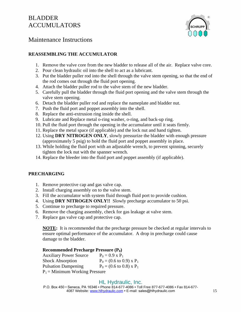
REASSEMBLING THE ACCUMULATOR
1. Remove the valve core from the new bladder to release all of the air. Replace valve core.2. Pour clean hydraulic oil into the shell to act as a lubricant.3. Put the bladder puller rod into the shell through the valve stem opening, so that the end of
the rod comes out through the fluid port opening.4. Attach the bladder puller rod to the valve stem of the new bladder.5. Carefully pull the bladder through the fluid port opening and the valve stem through the
valve stem opening.6. Detach the bladder puller rod and replace the nameplate and bladder nut.7. Push the fluid port and poppet assembly into the shell.8. Replace the anti-extrusion ring inside the shell.9. Lubricate and Replace metal o-ring washer, o-ring, and back-up ring.10. Pull the fluid port through the opening in the accumulator until it seats firmly.11. Replace the metal space (if applicable) and the lock nut and hand tighten.12. Using DRY NITROGEN ONLY, slowly pressurize the bladder with enough pressure
(approximately 5 psig) to hold the fluid port and poppet assembly in place.13. While holding the fluid port with an adjustable wrench, to prevent spinning, securely
tighten the lock nut with the spanner wrench.14. Replace the bleeder into the fluid port and poppet assembly (if applicable).
PRECHARGING
1. Remove protective cap and gas valve cap.2. Install charging assembly on to the valve stem.3. Fill the accumulator with system fluid through fluid port to provide cushion.4. Using DRY NITROGEN ONLY!! Slowly precharge accumulator to 50 psi.5. Continue to precharge to required pressure.6. Remove the charging assembly, check for gas leakage at valve stem.7. Replace gas valve cap and protective cap.
NOTE: It is recommended that the precharge pressure be checked at regular intervals toensure optimal performance of the accumulator. A drop in precharge could causedamage to the bladder.
Recommended Precharge Pressure (P0)Auxiliary Power Source P0 = 0.9 x P1 Shock Absorption P0 = (0.6 to 0.9) x P1Pulsation Dampening P0 = (0.6 to 0.8) x P1P1 = Minimum Working Pressure

HL Hydraulic, Inc. P.O. Box 450 • Seneca, PA 16346 • Phone 814-677-4086 • Toll Free 877-677-4086 • Fax 814-677-
4087 Website: www.hlhydraulic.com • E-mail: [email protected]
16
BLADDER ACCUMULATORS
Maintenance Instructions
ACCUMULATOR ASSEMBLY ITEM DESCRIPTION
1 SHELL 2 BLADDER 3 NAME PLATE 4 GAS VALVE 5 BLADDER NUT 6 PROTECTIVE CAP 7 FLUID PORT ASSEMBLY 8 ANTI-EXTRUSION RING 9 METAL O-RING WASHER 10 O-RING 11 BACK-UP RING 12 METAL SPACER
13 LOCK NUT 14 BLEEDER PLUG 15 BLEEDER PLUG O-RING
Note: Item 12, Metal Spacer, is no longer required in all applications.
BLADDER KIT ITEM DESCRIPTION
2 BLADDER 4 GAS VALVE 9 METAL O-RING WASHER 10 O-RING 11 BACK-UP RING

HL Hydraulic, Inc. P.O. Box 450 • Seneca, PA 16346 • Phone 814-677-4086 • Toll Free 877-677-4086 • Fax 814-677-
4087 Website: www.hlhydraulic.com • E-mail: [email protected] 17
BLADDER ACCUMULATORS
Specification No. ADA-HTR
Top Repairable TECHNICAL
Maximum Working Pressure: 3045 psi Test Pressure: 4567 psi Nominal Capacities: 20, 40, 90 cu.in., 1, 2.5 Gal.
DESIGN
Body: Carbon steel painted black. An optional body construction with Zinc Dichromate plating, internally and externally, is available by adding a T to the end of the part number.
Gas Valve: Standard: SCA-162, Pmax = 4350 psi Optional: SCA-53, Pmax = 3000 psi
Bladder: Buna-N (Alternatives Available). Bladder is suitable for use with mineral oils and non-aggressive fluids.
Installation: Mounted in any position.
Working Temperatures: 5°F ⇒ 194°F
Pressure Ratio: Recommended: P2:P0 = 2.5:1 Maximum: P2:P0 = 4:1
Special Modifications: Diaphragms for working temperatures from –60°F ⇒ 180°F
Part No.Gas
VolumeMax. W.P.
Weight Max. Flow Dimensions, inch (mm)
Hydraulic Ports
Figure No.
ADA-HTRcu. in.
(Liters)PSI
(bar)lbs.
(Kg.)gpm
(l/min) H D C BF Size
(Thread)20CI 21.4 3045 5.5 11.9 6.10 3.62 0.91 0.79 M 18 x1.5 1
(0.35) (210) (2.5) (45) (155) (92) (23) (20)40CI 42.7 3045 8.2 10.6 8.66 3.62 0.91 0.79 M 18 x1.5 1
(0.7) (210) (3.7) (40) (220) (92) (23) (20)90CI 91.5 3045 13.0 10.6 10.43 4.53 0.91 0.98 M 18 x1.5 1
(1.5) (210) (5.9) (40) (265) (115) (23) (25)1GAL 274.6 3045 30.9 58.1 14.37 6.69 0.91 1.97 3/4" BSP 2
(4.5) (210) (14) (220) (365) (170) (23) (50)1GAL.1 274.6 3045 35.3 105.6 15.55 6.69 0.91 3.15 1-1/4" BSP 2
(4.5) (210) (16) (400) (395) (170) (23) (80)2.5GAL 610.2 4350 68.4 79.3 25.20 6.69 0.91 3.15 1-1/4" BSP 2
(10) (300) (31) (300) (640) (170) (23) (80)All dimensions subject to change without notice.
Fig. 1 Fig. 2

HL Hydraulic, Inc. P.O. Box 450 • Seneca, PA 16346 • Phone 814-677-4086 • Toll Free 877-677-4086 • Fax 814-677-
4087 Website: www.hlhydraulic.com • E-mail: [email protected]
18
DIAPHRAGM ACCUMULATORS
Specification No. ADA-H
TECHNICAL
Maximum Working Pressure: 3045 psi Test Pressure: 4567 psi Nominal Capacities: 10, 20, 25, 40, 60, 85 cu.in.
DESIGN
Body: Cold formed steel with ends welded in protected argon atmosphere.
Diaphragm: Buna-N (Alternatives Available). Non replaceable diaphragm is suitable for use with mineral oils and non-aggressive fluids.
Installation: Mounted in any position.
Working Temperatures: 5°F ⇒ 194°F
Pressure Ratio: Recommended: P2:P0 = 2.5:1 Maximum: P2:P0 = 4:1
Special Modifications: Diaphragms for working temperatures from –60°F ⇒ 180°F
Part No.Gas
VolumeMax. W.P.
Weight Max. Flow Dimensions, inch (mm)
Hydraulic Ports
ADA-Hcu. in.
(Liters)PSI
(bar)lbs.
(Kg.)gpm
(l/min) H D E C B F Size (Thread)
10CI 9.2 3625 2.6 10.6 5.59 2.76 1.77 0.91 0.59 SAE #8(0.15) (250) (1.2) (40) (142) (70) (45) (23) (15) (3/4"-16)
20CI 21.4 3625 3.8 9.2 8.07 2.76 1.38 0.91 0.59 SAE #8(0.35) (250) (1.7) (35) (205) (70) (35) (23) (15) (3/4"-16)
25CI 27.5 3625 4.2 13.2 6.57 3.62 2.17 0.91 0.67 SAE #8(0.45) (250) (1.9) (50) (167) (92) (55) (23) (17) (3/4"-16)
40CI 42.7 3625 6.0 10.6 8.66 3.62 1.57 0.91 0.67 SAE #8(0.7) (250) (2.7) (40) (220) (92) (40) (23) (17) (3/4"-16)
60CI 61.0 3625 7.7 13.2 7.87 4.53 2.36 0.91 0.75 SAE #8(1.0) (250) (3.5) (50) (200) (115) (60) (23) (19) (3/4"-16)
85CI 85.4 3625 10.8 10.6 10.63 4.53 2.36 0.91 0.75 SAE #8(1.4) (250) (4.9) (40) (270) (115) (60) (23) (19) (3/4"-16)
120CI 122 3625 12.8 10.6 13.78 4.53 2.36 0.91 0.75 SAE #8(2.0) (250) (5.8) (40) (350) (115) (60) (23) (19) (3/4"-16)
1GAL 231 3045 30.9 21.1 12.60 6.69 3.74 0.91 0.59 3/4" BSP(3.8) (210) (14) (80) (320) (170) (95) (23) (15)
All dimensions subject to change without notice.

HL Hydraulic, Inc. P.O. Box 450 • Seneca, PA 16346 • Phone 814-677-4086 • Toll Free 877-677-4086 • Fax 814-677-
4087 Website: www.hlhydraulic.com • E-mail: [email protected] 19
DIAPHRAGM ACCUMULATORS
Specification No. ADA-HST
TECHNICAL
Maximum Working Pressure: 4350 psi Test Pressure: 6525 psi Nominal Capacities: 5, 20, 30, 50, 80, 90, 140 cu.in.
DESIGN
Body: Forged steel machined and externally painted black. The accumulator body and cap consists of a special thread that results in the two halves to be normally self-locking under pressure. An optional body construction with Zinc Dichromate plating, internally and externally, is available by adding a T to the end of the part number.
Gas Valve: Standard: SCA-162, Pmax = 4350 psi Optional: SCA-53, Pmax = 3000 psi
Diaphragm: Buna-N (Alternatives Available)
Installation: Mounted in any position.
Working Temperatures: 5°F ⇒ 194°F
Pressure Ratio: Recommended: P2:P0 = 2.5:1 Maximum: P2:P0 = 6:1
Special Modifications: Diaphragms for working temperatures from –60°F ⇒ 300°F
Part No.Gas
VolumeMax. W.P.
Weight Max. Flow Dimensions, inch (mm)
Hydraulic Ports
Figure No.
ADA-HSTcu. in.
(Liters)PSI
(bar)lbs.
(Kg.)gpm
(l/min) H D E C B F Size (Thread)
5CI 7 4350 4.6 11.9 5.55 3.11 2.95 0.91 3.58 SAE #8 1(0.12) (300) (2.1) (45) (141) (79) (75) (23) (91) (3/4"-16)
20CI 21 4350 7.1 13.2 6.02 3.90 3.74 0.91 3.58 SAE #8 1(0.35) (300) (3.2) (50) (153) (99) (95) (23) (91) (3/4"-16)
30CI 30 4350 11.0 15.9 6.30 4.88 4.53 0.91 4.21 SAE #8 1(0.5) (300) (5.0) (60) (160) (124) (115) (23) (107) (3/4"-16)
50CI 49 4350 12.8 15.9 7.09 5.43 4.72 0.91 3.03 SAE #8 2(0.8) (300) (5.8) (60) (180) (138) (120) (23) (77) (3/4"-16)
80CI 80 4350 17.5 14.5 9.06 4.88 4.53 0.91 7.68 SAE #8 1(1.3) (300) (7.9) (55) (230) (124) (115) (23) (195) (3/4"-16)
90CI 92 4350 19.2 14.5 10.63 5.43 4.72 1.91 6.69 SAE #8 2(1.5) (300) (8.7) (55) (270) (138) (120) (23) (170) (3/4"-16)
140CI 140 4350 23.2 14.5 14.17 5.43 4.72 0.91 6.69 SAE #8 2(2.3) (300) (10.5) (55) (360) (138) (120) (23) (170) (3/4"-16)
All dimensions subject to change without notice
Fig. 1
Fig. 2

HL Hydraulic, Inc. P.O. Box 450 • Seneca, PA 16346 • Phone 814-677-4086 • Toll Free 877-677-4086 • Fax 814-677-
4087 Website: www.hlhydraulic.com • E-mail: [email protected]
20
DIAPHRAGM ACCUMULATORS
Specification No. ADA-HSTPVC ADA-HSTP
TECHNICAL
Maximum Working Pressure: 145 psi Test Pressure: 217 psi Nominal Capacities: 5, 20, 40, 50, 90, 140, 300, 600 cu.in.
DESIGN
Body: PVC or Polypropylene constructed in two parts and joined with a special thread that under conditions of dynamic pressure tends to self-lock.
Diaphragm: Buna-N (Standard), Butyl, Nitrile, Polyurethane, EPDM, Viton, PVC, Hytrel, Alcryn
Installation: Mounted in any position.
Max. Working Temperatures: 122°F (PVC) 158°F (Polypropylene)
Pressure Ratio: Recommended: P2:P0 = 2.5:1 Maximum: P2:P0 = 6:1
Part No. Part No.Gas
VolumeMax. W.P.
Weight Dimensions, inch (mm)Hydraulic
Ports
ADA-HSTPVC ADA-HSTPcu. in.
(Liters)PSI
(bar)lbs.
(Kg.) H D C F Size (Thread)
5CI 5CI 7 145 2.6 5.43 3.15 0.91 SAE #6(0.12) (10) (1.2) (138) (80) (23) (9/16"-18)
20CI 20CI 21 145 4.0 6.10 3.94 0.91 SAE #8(0.35) (10) (1.8) (155) (100) (23) (3/4"-16)
40CI 40CI 43 145 5.3 8.07 3.94 0.91 SAE #8(0.7) (10) (2.4) (205) (100) (23) (3/4"-16)
50CI 50CI 49 145 8.6 7.09 5.51 0.91 SAE #8(0.8) (10) (3.9) (180) (140) (23) (3/4"-16)
90CI 90CI 92 145 13.2 10.63 5.51 1.91 SAE #12(1.5) (10) (6.0) (270) (140) (23) (1 1/16"-12)
140CI 140CI 140 145 22.0 14.17 5.51 0.91 SAE #12(2.3) (10) (10.0) (360) (140) (23) (1 1/16"-12)
300CI 300CI 305 145 39.7 16.93 7.87 0.91 SAE #24(5) (10) (18.0) (430) (200) (23) (1 7/8"-12)
600CI 600CI 610 145 57.3 16.93 7.87 0.91 SAE #32(10) (10) (26) (730) (200) (23) (2 1/2"-12)
All dimensions subject to change without notice

HL Hydraulic, Inc. P.O. Box 450 • Seneca, PA 16346 • Phone 814-677-4086 • Toll Free 877-677-4086 • Fax 814-677-
4087 Website: www.hlhydraulic.com • E-mail: [email protected] 21
DIAPHRAGM ACCUMULATORS
Specification No. ADA-HSTX
TECHNICAL
Max. Working Pressure: 2175 / 3045 psi On special request Working Pressure up to 7250 psi.
Test Pressure: 3250 / 4400 psi, Nominal Capacities: 5, 20, 30, 40, 50, 90, 140,
275, 600 cu.in.
DESIGN
Body: 316 stainless steel, constructed in two parts and joined with a special thread that under conditions of dynamic pressure tends to self-lock. Constructed in accordance with ASME Sec. VIII, Div. 1
Diaphragm Available: Buna-N (Standard), Viton, Butyl, EPDM, Nitrile, etc.
Installation: Mounted in any position.
Pressure Ratio: Recommended: P2:P0 = 2.5:1 Maximum: P2:P0 = 4:1
Part No.Gas
VolumeMax. W.P.
Weight Dimensions, inch (mm)Hydraulic
PortsFigure
No.
ADAcu. in.
(Liters)PSI
(bar)lbs.
(Kg.) H D E C BF Size
(Thread)HSTX-5CI 6 2175/3045 4.9 5.43 3.11 2.95 0.91 3.58 BSP #6 1
(0.1) (150/210) (2.2) (138) (79) (75) (23) (91) (3/8-19)HSTX- 20CI 21 2175/3045 8.2 6.10 3.94 3.70 0.91 3.82 BSP #8 1
(0.35) (150/210) (3.7) (155) (100) (94) (23) (97) (1/2-14)HSTX-30CI 30 2175/3045 12.2 6.30 4.84 4.84 0.91 4.21 BSP #8 1
(0.5) (150/210) (5.5) (160) (123) (123) (23) (107) (1/2-14)HSTX-40CI 40 2175/3045 11.1 8.07 3.94 3.70 0.91 6.30 BSP #8 1
(0.7) (150/210) (5) (205) (100) (94) (23) (160) (1/2-14)HSTX-50CI 49 2175/3045 13.5 7.09 5.43 4.72 0.91 3.03 BSP #8 2
(0.8) (150/210) (6.1) (180) (138) (120) (23) (77) (1/2-14)HSTX-90CI 92 2175/3045 19.2 10.63 5.43 4.72 0.91 6.69 BSP #12 2
(1.5) (150/210) (8.7) (270) (138) (120) (23) (170) (3/4"-14)HSTX-140CI 140 2175/3045 23.2 14.17 5.43 4.72 0.91 6.69 BSP #12 2
(2.3) (150/210) (10.5) (360) (138) (120) (23) (170) (3/4"-14)HSTX-275CI 275 2175/3045 53.0 14.57 7.09 7.09 0.71 - BSP #12 3
(4.5) (150/210) (27) (370) (180) (180) (18) - (3/4"-14)HSTX-600CI 610 2175/3045 100.0 29.13 7.09 - 0.71 - BSP #20 3
(10) (150/210) (45) (740) (180) - (18) - (1 1/4"-11)All dimensions subject to change without notice
Fig. 2 Fig. 3
Fig. 1

HL Hydraulic, Inc. P.O. Box 450 • Seneca, PA 16346• Phone 814-677-4086 • Toll Free 877-677-4086 • Fax 814-677-
4087 Website: www.hlhydraulic.com • E-mail: [email protected]
22
DIAPHRAGM ACCUMULATORS
CHARGING ASSEMBLY
Specification No. SCA-160 TECHNICAL
The precharge valve is an essential device for filling and checking nitrogen precharge in accumulators. Made of plated carbon steel, this valve can be used for a maximum working pressure of 350 Bar. It is supplied in a special case that includes a pressure gauge and 7 foot of hose for connection to the nitrogen bottle.
INSTRUCTION FOR USE How To Check Nitrogen Pressure: a) If the accumulator is connected to the system, please check that there isno pressure on the oil side. Turn the valve control knob counterclockwise until it is fully disengaged and install it on the accumulator. b) Close the nitrogen discharge valve and turn the “AR“ valve knobclockwise until the pressure gauge signals there that there is no internal pressure left or the knob is fully turned clockwise in the event that the accumulator is fully discharged. c) Once the nitrogen pressure is checked, slowly unscrew the dischargevalve until the pressure starts decreasing. Once the desired nitrogen pressure is reached, fully unscrew the control valve knob, and open the nitrogen discharge valve to eliminate any residual pressure and then unscrew the “AR” valve from the accumulator and re-install the protective cap of the nitrogen valve on accumulator. Be sure that the protective cap is tightened securely. Filling Of Nitrogen: Repeat the above mentioned operations connecting the nitrogen bottle quick release coupling before opening the control valve knob. Start filling the nitrogen very slowly. We recommend the use of a gas pressure reducing valve installed on the bottle in order to avoid over-pressurization of the accumulator body during the filling operation, especially when the precharge pressure is low. Check nitrogen precharge approximately every six months.
GAS VALVE
Specification No. SCA-162 TECHNICAL
The SCA-162 type valves mounted on our accumulators are made of plated carbon steel and can be used at a maximum working pressure of 400 Bar. In addition to their use on accumulators, they are a safety device for use on pressure vessels for various other applications of filling or controlling of a gas/fluid charge. These valves can also be used for an air drain on closed loop systems. They are also available in AISI 303 stainless steel.

HL Hydraulic, Inc. P.O. Box 450 • Seneca, PA 16346 • Phone 814-677-4086 • Toll Free 877-677-4086 • Fax 814-677-
4087 Website: www.hlhydraulic.com • E-mail: [email protected] 23
BLADDER TYPE PULSATION DAMPENER
Specification No. HBX TECHNICAL
Max. Working Pressure: See Data Below Test Pressure: See Data Below Nominal Capacities: 1.3, 2.5, 5, & 6.5 Gallon
DESIGN
Body: 316 stainless steel, constructed in three parts and joined with a special thread that under conditions of dynamic pressure tends to self-lock. Constructed in accordance with ASME Sec. VIII, Div. 1
Bladders Available: Buna-N, Butyl, Nitrile, Vamac, Silicone, Hypalon, Polyurethane, EPDM, etc.
Installation: Mounted in vertical position with the gas valve on top.
Pressure Ratio: Recommended: P2:P0 = 2.5:1 Maximum: P2:P0 = 4:1
* Note: the number of cycles is inverselyproportional to the increase of the compression ratio. For pulsation dampener applications the nitrogen precharge must be from 60% to 80% of the working pressure.
Part No.Gas
VolumeMax. W.P.
Test Press.
Weight Max. Flow Dimensions, inch (mm)
Hydraulic Ports
cu. in. (Liters)
PSI (bar)
PSI (bar)
lbs. (Kg.)
gpm (l/min) H D CH C B
F Size (Thread)
HBX-1.3gal 305 3045 4567 55.1 47.5 31.50 4.92 2.56 1.38 2.36 1 1/4" NPT(5) (20) (315) (25) (180) (800) (125) (65) (35) (60)
HBX-2.5gal 610 3045 4567 108.0 97.7 29.13 7.09 3.15 1.38 2.36 2" NPT(10) (210) (315) (49) (370) (740) (180) (80) (35) (60)
HBX-5gal 1129 2175 3262 165.4 132.1 33.46 8.66 3.86 1.77 3.94 3" NPT(18.5) (150) (225) (75) (500) (850) (220) (98) (45) (100)
HBX-6.5gal 1520 2175 3262 198.4 145.3 39.76 8.66 3.86 1.77 3.94 3" NPT(24.9) (150) (225) (90) (550) (1010) (220) (98) (45) (100)
All dimensions subject to change without notice

HL Hydraulic, Inc. P.O. Box 450 • Seneca, PA 16346 • Phone 814-677-4086 • Toll Free 877-677-4086 • Fax 814-677-
4087 Website: www.hlhydraulic.com • E-mail: [email protected]
24
BLADDER TYPE PULSATION DAMPENER
Specification No. HTRX BXT
Top Repairable TECHNICAL
Max. Working Pressure: See Data Below Test Pressure: See Data Below Nominal Capacities: HTRX: 0.4 & 1.2 Gallon
BXT: 2.5, 5, & 6.5 Gallon
DESIGN
Body: 316 stainless steel, constructed in three parts welded together. Constructed in accordance with ASME Sec. VIII, Div. 1
Bladders Available: Buna-N, Butyl, Nitrile, Vamac, Silicone, Hypalon, Polyurethane, EPDM, etc.
Installation: Mounted in vertical position with the gas valve on top.
Pressure Ratio: Recommended: P2:P0 = 2.5:1 Maximum: P2:P0 = 4:1
* Note: the number of cycles is inverselyproportional to the increase of the compression ratio. For pulsation dampener applications the nitrogen precharge must be from 60% to 80% of the working pressure.
Part No.Gas
VolumeMax. W.P.
Test Press.
Weight Max. Flow Dimensions, inch (mm)
Hydraulic Ports
ADAcu. in.
(Liters)PSI
(bar)PSI
(bar)lbs.
(Kg.)gpm
(l/min) H D CH C BF Size
(Thread)HTRX-0.4gal 92 1015 1523 14.80 39.6 10.63 4.49 3.15 0.79 - 1" NPT
(1.5) (70) (105) (6.7) (150) (270) (114) (80) (20) -HTRX- 1.2gal 275 725 1088 22.0 52.8 13.78 6.61 3.54 1.77 - 1 1/2" NPT
(4.5) (50) (75) (10) (200) (350) (168) (90) (45) -BXT-2.5gal 610 725 1088 35.3 47.5 29.92 6.61 2.76 1.57 1.73 2" BSP
(10) (50) (75) (16) (180) (760) (168) (70) (40) (44)BXT-5gal 1129 435 652 57.3 52.8 29.13 8.66 3.70 2.36 2.05 3" BSP
(18.5) (30) (45) (26) (200) (740) (220) (94) (60) (52)BXT-6.5gal 1520 435 652 66.2 47.5 35.04 8.66 3.70 2.36 2.05 3" BSP
(24.9) (30) (45) (31) (180) (890) (220) (94) (60) (52)All dimensions subject to change without notice
HTRX BXT
Fig. 1

HL Hydraulic, Inc. P.O. Box 450 • Seneca, PA 16346 • Phone 814-677-4086 • Toll Free 877-677-4086 • Fax 814-677-
4087 Website: www.hlhydraulic.com • E-mail: [email protected] 25
ACCUMULATOR SPECIAL EXECUTIONS TECHNICAL
The catalog does not include all of the special modifications that are available from SCHRUPP. We recommend therefore that you contact our technical office concerning any special request, which cannot be satisfied by our standard product.
Following is a list of a few examples of special products already manufactured by SCHRUPP:
-Special flanges per request.
-Accumulators for very high pressures (7000-14000 psi) both in carbon steel and stainless steel.
-Accumulators in preheat vapor chambers
-Accumulators for pulsation dampening in both carbon steel and stainless steel.
-Accumulators manufactured in polypropylene and nylon.
-Accumulators manufactured in hastelloy.
-Inline silencers without elastomers for aggressive fluids.
-Inline silencers without elastomers for extremely high temperature fluids.
-Inline silencers with elastomers without precharge pressure.
-P.T.F.E. diaphragm dampers with stainless steel, PVC or polypropylene construction.