Embed Size (px)
Citation preview
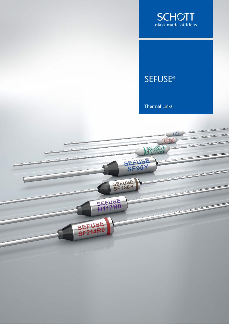
SEFUSE®
Thermal Links
SCHOTT Japan Corporation3-1 Nichiden, Minakuchi-cho, Koka-shi, Shiga 528-0034, JapanPhone +81-(0)748-63-6629Fax +81-(0)[email protected]/epackaging
70219 ENGLISH 08/2018 Printed in Japan
This printed matter uses FSC® certified paper using properly controlled forest
wood. Furthermore, it uses vegetable-oil-based ink including soy oil-based ink
and waterless printing that does not discharge any hazardous waste fluids.

2 23
Storage
The body and lead A of the SF-type, and the leads of SM092A, SM092B, SM225A, SM225B and SM225G are silver-plated. Therefore, these parts may discolor because of sulfuration, making the markings on the body illegible or negatively affecting the solder-ability of the lead. To avoid this, the thermal link should not be kept around materials (such as cardboard or rubber, etc.) which generate sulfurous acid gas.
When storage in cardboard boxes is required, thermal links should be double packed and sealed in polybags such as polyethylene.
Recommendation
SCHOTT recommends the following tests upon receipt and after mounting of the thermal link, as it may have undergone some mechanical load or thermal influence during transportation or when being mounted.1. Appearance check2. Resistance check (comparing before with after), or conductive check3. X-ray inspection4. Operation check for sampling
Be careful when mounting the thermal link because external force, heat or a harmful atmosphere (containing excessive humidity or sulfurous acid gas) may damage the thermal link.
If applicable, it is recommended that the general consumers, who are unaware of the usage cautions for thermal links, be informed not to mount, remove, or replace the thermal link through a note to this effect in the user's manual and other related material.
All reasonable care has been taken to present the data here and the values contained in this document were obtained under certain testing conditions by us. They are not guaranteed and are for reference only.For any clarifications or more information about these cautions, please kindly contact SCHOTT.
The information herein is based on the documents as of August 2018, and is subject to change without notice. Therefore it is recommended to refer to latest individual information such as drawing for mass production designing. The latest product information will also be made available on www.schott.com/epackaging for your reference.
It is prohibited to reprint or copy the contents herein without prior written agreement from SCHOTT Japan Corporation.
Please note that should any problems relevant to the industrial property of third parties occur with the use of products from SCHOTT Japan Corporation, the company would not assume any responsibility for matters other than the ones directly related to the structure or the manufacturing process of the products supplied by SCHOTT Japan Corporation.
Although continuous efforts to improve the quality and reliability of our products are in place, the possibility of defects cannot be entirely eliminated. Therefore when using our electronic component products, please ensure that sufficient safety measures are included in the design of the final application, such as redundancy, fire containment and malfunction prevention against physical injuries, fire disasters and social damages in consideration of the said defect occurrences.
Our products are classified into 2 groups: “Standard” and “Special”. The recommended applications of the products according to its quality level are indicated below. If you intend to use our products for applications other than “Standard” level, please consult with our sales representative in advance.
"Standard"
Computers, office equipment, communication equipment, measuring equipment, audio & visual equipment, home electric appliances, machine tools, personal electrical equipment and industrial robots, etc.
"Special"
Transportation equipment (automobiles, trains, ships and others), aircrafts, aerospace equipment, medical equipment for life support, etc.
SCHOTT is a leading international technology group in the areas of specialty glass and glass-ceramics. With more than 130 years of outstanding development, materials and technology expertise we offer a broad portfolio of high-quality products and intelligent solutions that contribute to our customers’ success.For several decades, SCHOTT has been a leading developer and manufacturer of thermal links. These safety devices serve a broad range of applications, including home appliances, li-ion batteries and automobiles. With many years of extensive experience and a strong development and manufacturing set-up, we can respond flexibly to market needs and customer requirements.
3
ContentsIntroduction, Advantages, Safety standards 3Design 4Applications 5Standard Ratings 6Performance Data 14Definition of Terms 18Lead Cutting and Taping 18Cautions 20
IntroductionSCHOTT develops and manufactures thermal link protection devices, widely known as SEFUSE®. These devices are designed to protect industrial and home electrical equipment from catching fire by sensing overheating and cutting off the electrical circuit immediately.There are two SEFUSE® types: SF and SM. Both types suit the needs of a wide range of applications. The SF-type uses thermosensitive material as the thermal pellet, while the SM-type uses a fusible alloy.
SCHOTT SEFUSE® Advantages:
Trusted: For many decades, SEFUSE® has been one of the most renowned a trusted brands of thermal links worldwide.
Safe & Reliable: SCHOTT SEFUSE® thermal links are highly reliable thermal protection devices that provide excellent, long-lasting performance and meet numerous international industrial safety standards, such as UL, VDE, CCC, PSE, etc. SEFUSE®
SF-type fuses, except SF/K series, have a ceramic pipe that alleviates stress that may occur on the sealing resin when the leads are bent, thereby reliably holding the leads in place.
Eco-friendly: SEFUSE® thermal links contain no hazardous substances and comply with WEEE and RoHS standards. In addition, the sliding contact of SEFUSE® SF-type thermal links are made of an environmentally-friendly silver copper oxide (AgCuO) material that is patented worldwide.
Safety standards
Please review the "Cautions" on pages 20 through 23 prior to using SEFUSE®.
VDE (Germany) BEAB (UK) PSE (Japan)CCC (China) UL (USA) cUL (Canada) KC (Korea)CSA (Canada)
4
Design
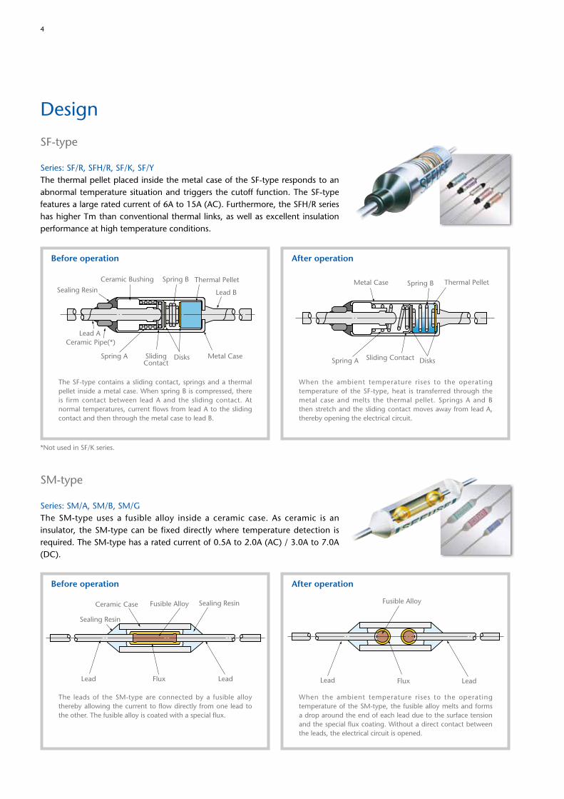
SF-type
Series: SF/R, SFH/R, SF/K, SF/YThe thermal pellet placed inside the metal case of the SF-type responds to an abnormal temperature situation and triggers the cutoff function. The SF-type features a large rated current of 6A to 15A (AC). Furthermore, the SFH/R series has higher Tm than conventional thermal links, as well as excellent insulation performance at high temperature conditions.
Thermal Pellet
Lead B
Lead A
Metal Case
Spring B
Spring A SlidingContact
Disks
Ceramic Bushing
Sealing Resin
Ceramic Pipe(*)
Metal Case Spring B
Spring A
Thermal Pellet
DisksSliding Contact
Before operation After operation
The SF-type contains a sliding contact, springs and a thermal pellet inside a metal case. When spring B is compressed, there is firm contact between lead A and the sliding contact. At normal temperatures, current flows from lead A to the sliding contact and then through the metal case to lead B.
When the ambient temperature rises to the operating temperature of the SF-type, heat is transferred through the metal case and melts the thermal pellet. Springs A and B then stretch and the sliding contact moves away from lead A, thereby opening the electrical circuit.
*Not used in SF/K series.
SM-type
Series: SM/A, SM/B, SM/GThe SM-type uses a fusible alloy inside a ceramic case. As ceramic is an insulator, the SM-type can be fixed directly where temperature detection is required. The SM-type has a rated current of 0.5A to 2.0A (AC) / 3.0A to 7.0A (DC).
Lead Lead
Ceramic Case Fusible Alloy Sealing Resin
Sealing Resin
Flux
Before operation
The leads of the SM-type are connected by a fusible alloy thereby allowing the current to flow directly from one lead to the other. The fusible alloy is coated with a special flux.
Lead LeadFlux
Fusible Alloy
After operation
When the ambient temperature rises to the operating temperature of the SM-type, the fusible alloy melts and forms a drop around the end of each lead due to the surface tension and the special flux coating. Without a direct contact between the leads, the electrical circuit is opened.

5
Applications
Small home appliancesCoffee makers, electric kettles, bread makers,rice cookers, hot plates, irons, hair dryers
*SF-type, SM-type
AutomotiveAutomotive air conditioners, seat heaters, engine cooling
*SF-type
Office equipmentCopiers, laser beam printers, facsimile copiers, power taps, etc.
*SF-type
Large home appliancesAirconditioners, refrigerators, washing machines, fan heaters, electrical toilets, gas boilers, electrical tables with heaters
*SF-type, SM-type
6
Marking 1 (SF70R*−SF129R*) Marking 2 (SF139R*−SF240R*)
** Factory Code represents the factory location as shown below Thailand : C
S E F U S E
S F 7 0 R 0
1392
73℃15A
Factory Code** Lot Number
Rated Current
Rated FunctioningTemperature
Part Number
Brand Name
How to read a lot number
Sub-lot number
MonthX……OctoberY……NovemberZ……December
Last two digit of year
ex.)
S E F U S E
S F 2 1 4 R 1
1392
216℃15A
Factory Code**
CCC Mark
Lot Number
Rated Current
Rated FunctioningTemperature
Part Number
Brand Name
CCC Mark
13 9 2
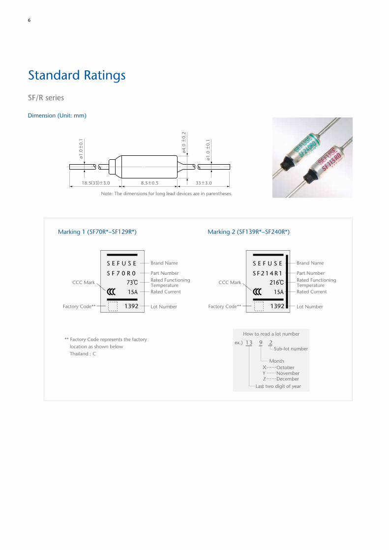
Standard Ratings
SF/R series
Dimension (Unit: mm)
ø1.0
±0.
1
18.5(33)±3.0 33 ±3.08.5 ±0.5
ø1.0
±0.
1
ø4.0
±0.
2
Note: The dimensions for long lead devices are in parentheses.
7
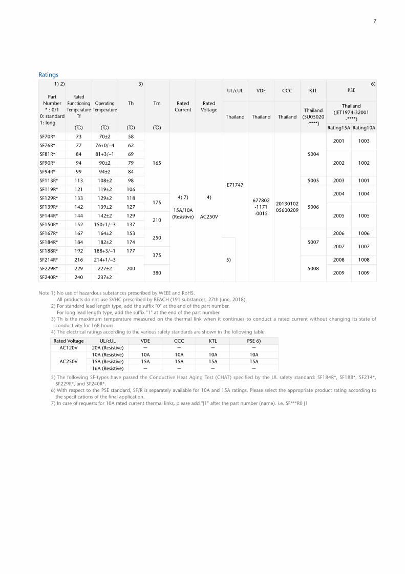
Ratings1) 2)
PartNumber* : 0/1
0: standard1: long
RatedFunctioningTemperature
Tf
(℃)
OperatingTemperature
(℃)
3)
Th
(℃)
Tm
(℃)
RatedCurrent
RatedVoltage
UL/cUL VDE CCC KTL6)
PSE
Thailand Thailand ThailandThailand
(SU05020-****)
Thailand(JET1974-32001
-****)
Rating15A Rating10A
SF70R* 73 70±2 58
165
4) 7)
15A/10A(Resistive)
4)
AC250V
E71747
677802-1171-0015
2013010205600209
5004
2001 1003SF76R* 77 76+0/−4 62
SF81R* 84 81+3/−1 69
2002 1002SF90R* 94 90±2 79
SF94R* 99 94±2 84
SF113R* 113 108±2 98 5005 2003 1001
SF119R* 121 119±2 106
5006
2004 1004SF129R* 133 129±2 118
175SF139R* 142 139±2 127
2005 1005SF144R* 144 142±2 129210
SF150R* 152 150+1/−3 137
SF167R* 167 164±2 153250
5007
2006 1006
SF184R* 184 182±2 174
5)
2007 1007SF188R* 192 188+3/−1 177
375SF214R* 216 214+1/−3
200 5008
2008 1008
SF229R* 229 227±2380 2009 1009
SF240R* 240 237±2
Note 1) No use of hazardous substances prescribed by WEEE and RoHS. All products do not use SVHC prescribed by REACH (191 substances, 27th June, 2018). 2) For standard lead length type, add the suffix "0" at the end of the part number. For long lead length type, add the suffix "1" at the end of the part number. 3) Th is the maximum temperature measured on the thermal link when it continues to conduct a rated current without changing its state of
conductivity for 168 hours. 4) The electrical ratings according to the various safety standards are shown in the following table.
5) The following SF-types have passed the Conductive Heat Aging Test (CHAT) specified by the UL safety standard: SF184R*, SF188*, SF214*, SF229R*, and SF240R*.
6) With respect to the PSE standard, SF/R is separately available for 10A and 15A ratings. Please select the appropriate product rating according to the specifications of the final application.
7) In case of requests for 10A rated current thermal links, please add "J1" after the part number (name). i.e. SF***R0 J1
Rated Voltage UL/cUL VDE CCC KTL PSE 6)AC120V 20A (Resistive) - - - -
AC250V10A (Resistive) 10A 10A 10A 10A15A (Resistive) 15A 15A 15A 15A16A (Resistive) - - - -
8
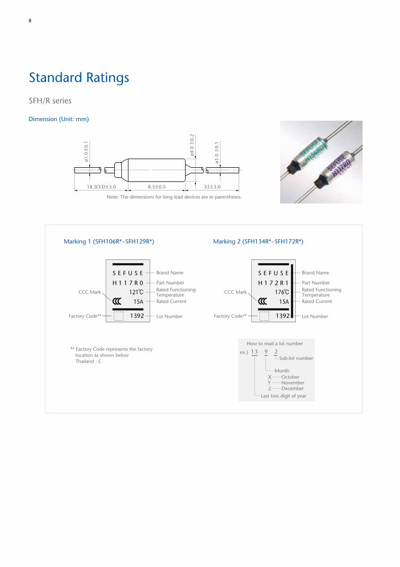
Standard Ratings
SFH/R series
Dimension (Unit: mm)
Marking 1 (SFH106R*−SFH129R*) Marking 2 (SFH134R*−SFH172R*)
** Factory Code represents the factory location as shown below Thailand : C
S E F U S E
H 1 1 7 R 0
1392
121℃15A
Factory Code**
CCC Mark
Lot Number
Rated Current
Rated FunctioningTemperature
Part Number
Brand Name
How to read a lot number
Sub-lot number
MonthX……OctoberY……NovemberZ……December
Last two digit of year
ex.)
S E F U S E
H 1 7 2 R 1
1392
176℃15A
Factory Code** Lot Number
Rated Current
Rated FunctioningTemperature
Part Number
Brand Name
CCC Mark
13 9 2
ø1.0
±0.
1
18.5(33)±3.0 33 ±3.08.5±0.5
ø1.0
±0.
1
ø4.0
±0.
2Note: The dimensions for long lead devices are in parentheses.
9
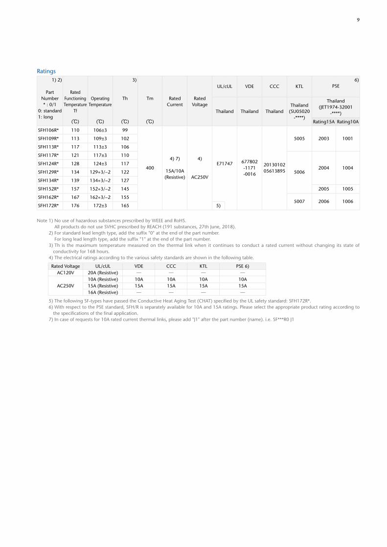
Ratings1) 2)
PartNumber* : 0/1
0: standard1: long
Rated Functioning Temperature
Tf
(℃)
OperatingTemperature
(℃)
3)
Th
(℃)
Tm
(℃)
RatedCurrent
RatedVoltage
UL/cUL VDE CCC KTL6)
PSE
Thailand Thailand ThailandThailand
(SU05020-****)
Thailand(JET1974-32001
-****)
Rating15A Rating10A
SFH106R* 110 106±3 99
400
4) 7)
15A/10A(Resistive)
4)
AC250V
E71747 677802-1171-0016
2013010205613895
5005 2003 1001SFH109R* 113 109±3 102
SFH113R* 117 113±3 106
SFH117R* 121 117±3 110
50062004 1004
SFH124R* 128 124±3 117
SFH129R* 134 129+3/−2 122
SFH134R* 139 134+3/−2 127
SFH152R* 157 152+3/−2 145 2005 1005
SFH162R* 167 162+3/−2 1555007 2006 1006
SFH172R* 176 172±3 165 5)
Note 1) No use of hazardous substances prescribed by WEEE and RoHS. All products do not use SVHC prescribed by REACH (191 substances, 27th June, 2018). 2) For standard lead length type, add the suffix "0" at the end of the part number. For long lead length type, add the suffix "1" at the end of the part number. 3) Th is the maximum temperature measured on the thermal link when it continues to conduct a rated current without changing its state of
conductivity for 168 hours. 4) The electrical ratings according to the various safety standards are shown in the following table.
5) The following SF-types have passed the Conductive Heat Aging Test (CHAT) specified by the UL safety standard: SFH172R*. 6) With respect to the PSE standard, SFH/R is separately available for 10A and 15A ratings. Please select the appropriate product rating according to
the specifications of the final application. 7) In case of requests for 10A rated current thermal links, please add "J1" after the part number (name). i.e. SF***R0 J1
Rated Voltage UL/cUL VDE CCC KTL PSE 6)AC120V 20A (Resistive) ─ ─ ─ ─
AC250V10A (Resistive) 10A 10A 10A 10A15A (Resistive) 15A 15A 15A 15A16A (Resistive) ─ ─ ─ ─
10
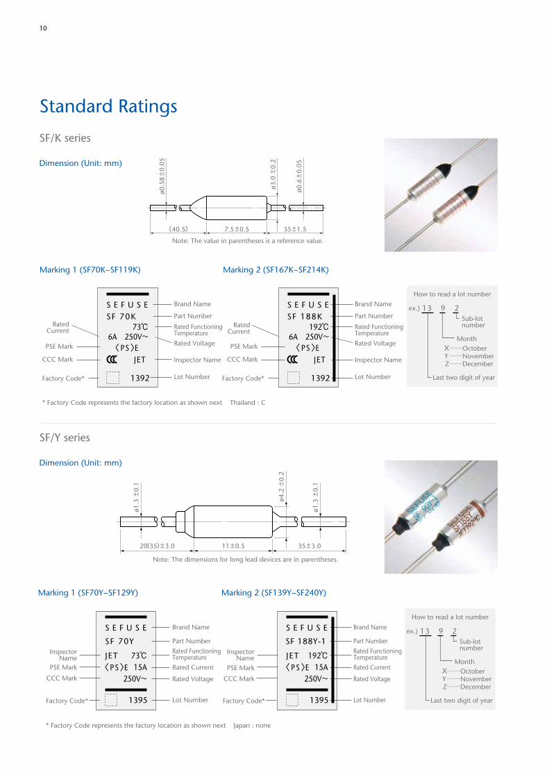
Standard Ratings
SF/K series
Dimension (Unit: mm)
SF/Y series
Dimension (Unit: mm)
ø0.5
8 ±
0.05
(40.5) 35 ±1.57.5 ±0.5
ø0.6
±0.
05
ø3.0
±0.
2
Note: The value in parentheses is a reference value.
Marking 1 (SF70K−SF119K) Marking 2 (SF167K−SF214K)
How to read a lot number
Last two digit of year
MonthX……October Y……November Z……December
ex.) S E F U S ESF 70K
1392
73℃6A 250V~
Inspector Name
PSE Mark
CCC Mark
Lot Number
Rated Voltage
RatedCurrent
Rated FunctioningTemperature
Part Number
Brand Name
〈 PS〉E
* Factory Code represents the factory location as shown next Thailand : C
Factory Code*
JET
S E F U S ESF 188K
1392
192℃6A 250V~
Inspector Name
Lot Number
Rated Voltage
RatedCurrent
Rated FunctioningTemperature
Part Number
Brand Name
〈 PS〉E
Factory Code*
JET
PSE Mark
CCC Mark
Sub-lotnumber
13 9 2
ø1.3
±0.
1
ø1.3
±0.
1
20(35) ±3.0 35 ±3.011 ±0.5
ø4.2
±0.
2
Note: The dimensions for long lead devices are in parentheses.
Marking 1 (SF70Y−SF129Y) Marking 2 (SF139Y−SF240Y)
S E F U S E
SF 70Y
1395
73℃15A
250V~
InspectorName
CCC Mark
PSE Mark
Lot Number
Rated Voltage
Rated Current
Rated FunctioningTemperature
Part Number
Brand Name
JET〈 PS〉E
Factory Code*
PSE Mark
S E F U S E
SF 188Y-1
1395
192℃15A
250V~
InspectorName
CCC Mark
Lot Number
Rated Voltage
Rated Current
Rated FunctioningTemperature
Part Number
Brand Name
JET〈 PS〉E
Factory Code*
* Factory Code represents the factory location as shown next Japan : none
How to read a lot number
Last two digit of year
Sub-lotnumber
MonthX……October Y……November Z……December
ex.) 13 9 2
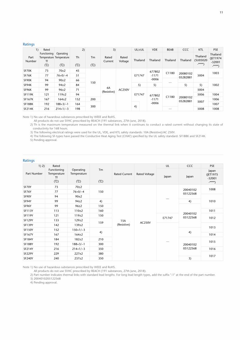
11
Ratings1)
PartNumber
Rated Functioning Temperature
Tf(℃)
OperatingTemperature
(℃)
2)
Th
(℃)
Tm
(℃)
3)
RatedCurrent
RatedVoltage
UL/cUL VDE BEAB CCC KTL PSE
Thailand Thailand Thailand ThailandThailand
(SU05020-****)
Thailand(JET1974-32001-****)
SF70K 73 70±2 45
150
6A (Resistive)
AC250V
E71747677802-1171-0006
C1180 2008010205282881
50041003
SF76K 77 76+0/−4 51
SF90K 94 90±2 66─
1002SF94K 99 94±2 84 5) 5) 5) 5)
SF96K 99 96±2 71
E71747 677802-1171-0006
C1180 2008010205282881
5004
SF119K 121 119±2 94 5006 1004
SF167K 167 164±2 152 2005007
1006
SF188K 192 188+3/−1 164300 4)
1007
SF214K 216 214+1/−3 198 ─ 5008 1008
Note 1) No use of hazardous substances prescribed by WEEE and RoHS. All products do not use SVHC prescribed by REACH (191 substances, 27th June, 2018). 2) Th is the maximum temperature measured on the thermal link when it continues to conduct a rated current without changing its state of
conductivity for 168 hours. 3) The following electrical ratings were used for the UL, VDE, and KTL safety standards: 10A (Resistive)/AC 250V. 4) The following SF-types have passed the Conductive Heat Aging Test (CHAT) specified by the UL safety standard: SF188K and SF214K. 5) Pending approval.
Ratings1) 2)
Part Number
Rated Functioning Temperature
Tf(℃)
OperatingTemperature
(℃)
Tm
(℃)
Rated Current Rated Voltage
UL CCC PSE
Japan Japan
Japan(JET1975-32001-****)
SF70Y 73 70±2
150
15A (Resistive)
AC250V
─
2004010205122568
1008SF76Y 77 76+0/−4
SF90Y 94 90±2
1010SF94Y 99 94±2 4) 4)
SF96Y 99 96±2 150
2004010205122568
SF113Y 113 110±2 160 1011
SF119Y 121 119±2 150E71747 1012
SF129Y 133 129±2159
SF139Y 142 139±2
─
1013SF150Y 152 150+1/−3
4) 4)SF167Y 167 164±2 1014
SF184Y 184 182±2 210
2004010205122568
1015SF188Y 192 188+3/−1 300
SF214Y 216 214+1/−3 350 1016
SF229Y 229 227±2 3801017
SF240Y 240 237±2 350 3)
Note 1) No use of hazardous substances prescribed by WEEE and RoHS. All products do not use SVHC prescribed by REACH (191 substances, 27th June, 2018). 2) Part number indicates thermal links with standard lead lengths. For long lead length types, add the suffix "-1" at the end of the part number. 3) 2004010205122568 4) Pending approval.
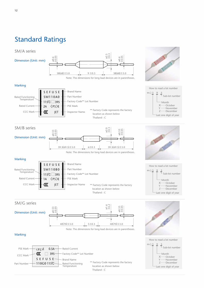
12
Standard Ratings
SM/A series
Dimension (Unit: mm)
Marking
ø0.6
±0.
05
ø0.6
±0.
05
38(68) ±3.0 38(68) ±3.09 ±0.3
ø2.5
±0.
3
Note: The dimensions for long lead devices are in parentheses.
115℃ 3952A
Inspector NameCCC Mark
PSE MarkRated Current
Rated FunctioningTemperature
Factory Code** Lot Number
Part Number
Brand NameS E F U S E
SM110A0
JET
〈 PS〉E
How to read a lot number
Sub-lot number
MonthX……OctoberY……NovemberZ……December
Last one digit of year
ex.) 3 9 5
** Factory Code represents the factory
location as shown below
Thailand : C
SM/B series
Dimension (Unit: mm)
Marking
ø0.5
3±
0.05
ø0.5
3±
0.05ø2
.0±
0.3
39.5(69.5) ±3.0 39.5(69.5) ±3.06 ±0.3
Note: The dimensions for long lead devices are in parentheses.
115℃ 3951A
S E F U S E
S M 1 1 0 B 0
JET Inspector NameCCC Mark
PSE MarkRated Current
Rated FunctioningTemperature
Factory Code** Lot Number
Part Number
Brand Name
〈 PS〉E
How to read a lot number
Sub-lot number
MonthX……OctoberY……NovemberZ……December
Last one digit of year
ex.) 3 9 5
** Factory Code represents the factory
location as shown below
Thailand : C
SM/G series
Dimension (Unit: mm)
Marking
ø0.5
3±
0.05
ø0.5
3±
0.05ø1
.6±
0.2
40(70) ±3.0 40(70) ±3.05 ±0.3
Note: The dimensions for long lead devices are in parentheses.
110G0 115℃
395
Rated FunctioningTemperature
Rated Current
Part Number
Brand NameS E F U S E
0.5APSE Mark < PS >E
CCC MarkFactory Code** Lot Number
How to read a lot number
Sub-lot number
MonthX……OctoberY……NovemberZ……December
Last one digit of year
ex.) 3 9 5
** Factory Code represents the factory
location as shown below
Thailand : C
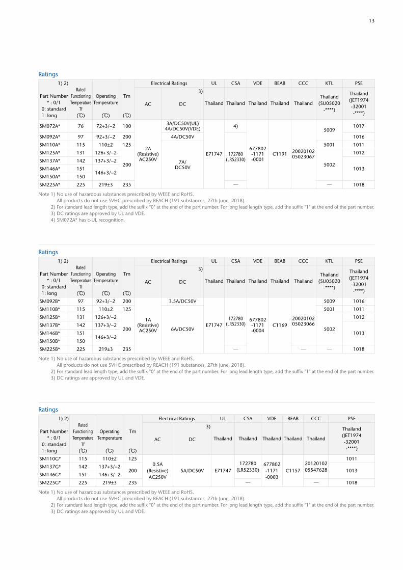
13
Ratings
Note 1) No use of hazardous substances prescribed by WEEE and RoHS. All products do not use SVHC prescribed by REACH (191 substances, 27th June, 2018). 2) For standard lead length type, add the suffix "0" at the end of the part number. For long lead length type, add the suffix "1" at the end of the part number. 3) DC ratings are approved by UL and VDE. 4) SM072A* has c-UL recognition.
1) 2)
Part Number* : 0/1
0: standard1: long
RatedFunctioningTemperature
Tf(℃)
OperatingTemperature
(℃)
Tm
(℃)
Electrical Ratings UL CSA VDE BEAB CCC KTL PSE
AC
3)
DC Thailand Thailand Thailand Thailand ThailandThailand
(SU05020-****)
Thailand(JET1974-32001-****)
SM072A* 76 72+3/−2 100
2A (Resistive)AC250V
3A/DC50V(UL)4A/DC50V(VDE)
E71747
4)
677802-1171-0001
C1191 2002010205023067
50091017
SM092A* 97 92+3/−2 200 4A/DC50V
172780(LR52330)
1016
SM110A* 115 110±2 125
7A/DC50V
5001 1011
SM125A* 131 126+3/−2
200 5002
1012
SM137A* 142 137+3/−2
1013SM146A* 151146+3/−2
SM150A* 150
SM225A* 225 219±3 235 ─ ─ 1018
Ratings
Note 1) No use of hazardous substances prescribed by WEEE and RoHS. All products do not use SVHC prescribed by REACH (191 substances, 27th June, 2018). 2) For standard lead length type, add the suffix "0" at the end of the part number. For long lead length type, add the suffix "1" at the end of the part number. 3) DC ratings are approved by UL and VDE.
1) 2)
Part Number* : 0/1
0: standard1: long
RatedFunctioningTemperature
Tf(℃)
OperatingTemperature
(℃)
Tm
(℃)
Electrical Ratings UL CSA VDE BEAB CCC KTL PSE
AC
3)
DC Thailand Thailand Thailand Thailand ThailandThailand
(SU05020-****)
Thailand(JET1974-32001-****)
SM092B* 97 92+3/−2 200
1A (Resistive)AC250V
3.5A/DC50V
E71747172780
(LR52330)677802-1171-0004
C11692002010205023066
5009 1016
SM110B* 115 110±2 125
6A/DC50V
5001 1011
SM125B* 131 126+3/−2
200 5002
1012
SM137B* 142 137+3/−2
1013SM146B* 151146+3/−2
SM150B* 150
SM225B* 225 219±3 235 ─ ─ ─ 1018
Ratings1) 2)
Part Number* : 0/1
0: standard1: long
RatedFunctioningTemperature
Tf(℃)
OperatingTemperature
(℃)
Tm
(℃)
Electrical Ratings UL CSA VDE BEAB CCC PSE
AC
3)
DC Thailand Thailand Thailand Thailand Thailand
Thailand(JET1974-32001-****)
SM110G* 115 110±2 1250.5A
(Resistive)AC250V
5A/DC50V E71747172780
(LR52330)677802-1171-0003
C11572012010205547628
1011
SM137G* 142 137+3/−2200 1013
SM146G* 151 146+3/−2
SM225G* 225 219±3 235 ─ ─ 1018
Note 1) No use of hazardous substances prescribed by WEEE and RoHS. All products do not use SVHC prescribed by REACH (191 substances, 27th June, 2018). 2) For standard lead length type, add the suffix "0" at the end of the part number. For long lead length type, add the suffix "1" at the end of the part number. 3) DC ratings are approved by UL and VDE.
14
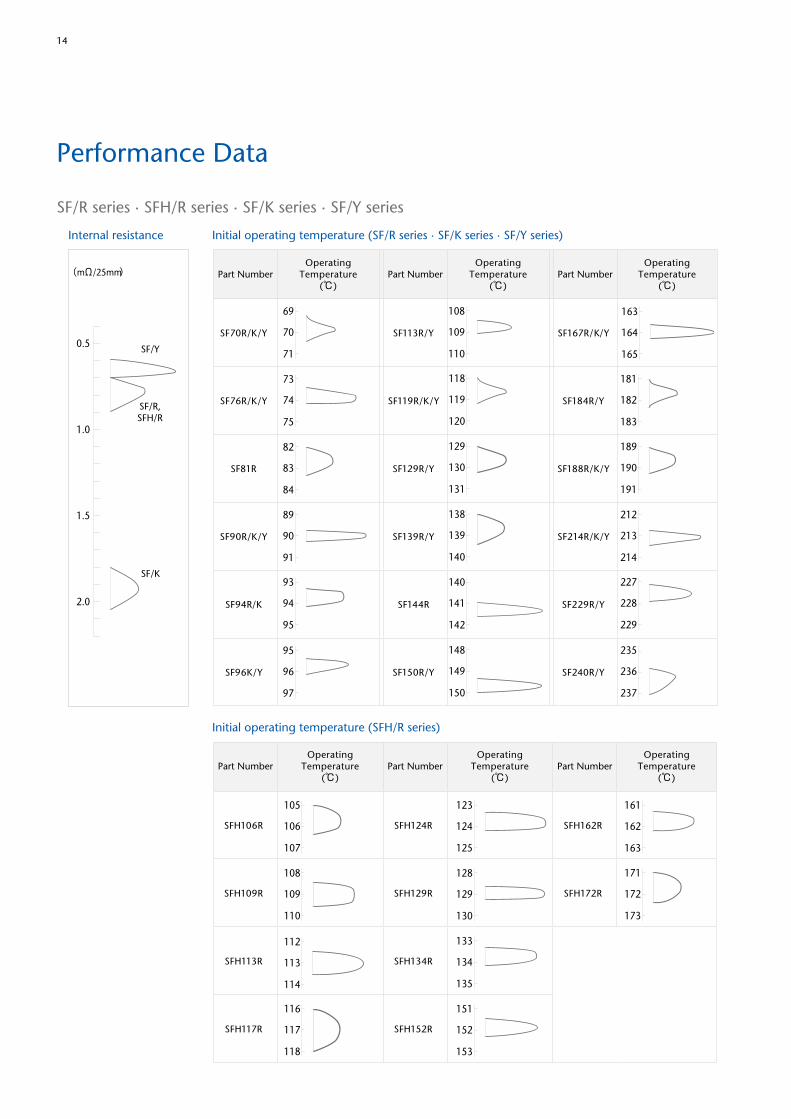
Performance Data
SF/R series ∙ SFH/R series ∙ SF/K series ∙ SF/Y series
(mΩ/25mm)
0.5
1.5
2.0
1.0
SF/Y
SF/R,SFH/R
SF/K
Internal resistance Initial operating temperature (SF/R series ∙ SF/K series ∙ SF/Y series)
Initial operating temperature (SFH/R series)
190
191
212
213
214
235
236
237
119
120
129
130
131
138
139
140
82
83
84
140
141
142
148
149
150
69
118
189
70
71
73
74
75
93
94
95
95
96
97
108
109
110
89
90
91
163
164
165
182
183
181
227
228
229
190
191
212
213
214
235
236
237
119
120
129
130
131
138
139
140
82
83
84
140
141
142
148
149
150
69
118
189
70
71
73
74
75
93
94
95
95
96
97
108
109
110
89
90
91
163
164
165
182
183
181
227
228
229
190
191
212
213
214
235
236
237
119
120
129
130
131
138
139
140
82
83
84
140
141
142
148
149
150
69
118
189
70
71
73
74
75
93
94
95
95
96
97
108
109
110
89
90
91
163
164
165
182
183
181
227
228
229
Part NumberOperating
Temperature(℃)
Part Number Part NumberOperating
Temperature(℃)
OperatingTemperature
(℃)
SF70R/K/Y SF113R/Y SF167R/K/Y
SF76R/K/Y SF119R/K/Y SF184R/Y
SF81R SF129R/Y SF188R/K/Y
SF90R/K/Y SF139R/Y SF214R/K/Y
SF94R/K SF144R SF229R/Y
SF96K/Y SF150R/Y SF240R/Y
172
173
124
125
128
129
130
133
134
135
151
152
153
105 123
171
106
107
108
109
110
116
117
118
112
113
114
162
163
161
172
173
124
125
128
129
130
133
134
135
151
152
153
105 123
171
106
107
108
109
110
116
117
118
112
113
114
162
163
161
172
173
124
125
128
129
130
133
134
135
151
152
153
105 123
171
106
107
108
109
110
116
117
118
112
113
114
162
163
161
SFH106R SFH124R SFH162R
SFH109R SFH129R SFH172R
SFH113R SFH134R
SFH117R SFH152R
Part NumberOperating
Temperature(℃)
Part NumberOperating
Temperature(℃)
Part NumberOperating
Temperature(℃)
15
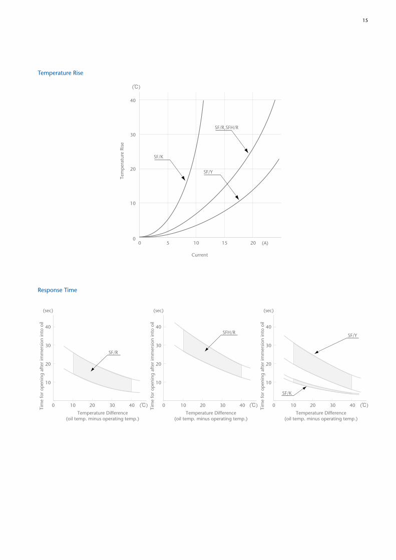
Temperature Rise
Response Time
(℃)
40
30
20
10
00 5 10 15 20
Current
SF/K
SF/Y
(A)
SF/R,SFH/RTe
mp
erat
ure
Rise
(℃)
40
30
20
10
10 20 30 400
(sec)
SF/K
SF/Y
(℃)
40
30
20
10
10 20 30 400
(sec)
SFH/R
)(℃
40
30
20
10
10 20 30 400
(sec)
SF/R
Temperature Difference(oil temp. minus operating temp.)
Tim
e fo
r op
enin
g af
ter
imm
ersi
on in
to o
il
Temperature Difference(oil temp. minus operating temp.)
Temperature Difference(oil temp. minus operating temp.)
Tim
e fo
r op
enin
g af
ter
imm
ersi
on in
to o
il
Tim
e fo
r op
enin
g af
ter
imm
ersi
on in
to o
il
16
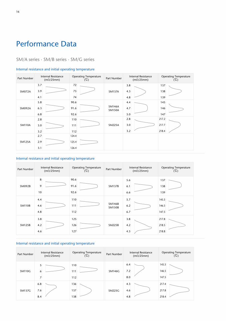
Performance Data
Internal resistance and initial operating temperature
Internal resistance and initial operating temperature
Internal resistance and initial operating temperature
72
73
74
3.7
3.9
4.1
124.4
125.4
126.4
2.7
2.9
3.1
90.6
91.6
92.6
5.8
6.3
6.8
137
138
139
3.8
4.3
4.8
Part NumberInternal Resistance
(mΩ/25mm)Internal Resistance
(mΩ/25mm)Operating Temperature
(℃)Operating Temperature
(℃) Part Number
SM072A
SM125A
SM092A
SM137A
110
111
112
2.8
3.0
3.2
145
146
147
4.4
4.7
5.0
217.2
217.7
218.4
2.8
3.0
3.2
SM110A
SM146ASM150A
SM225A
110
111
112
4.4
4.6
4.8
90.6
91.6
92.6
8
9
10
125
126
127
3.8
4.2
4.6
137
138
139
5.6
6.1
6.6
145.5
146.5
147.5
5.7
6.2
6.7
SM092B SM137B
SM110BSM146BSM150B
SM125B
217.8
218.5
218.8
3.8
4.2
4.3
SM225B
Part Number Part NumberInternal Resistance
(mΩ/25mm)Internal Resistance
(mΩ/25mm)Operating Temperature
(℃)Operating Temperature
(℃)
110
111
112
5
6
7
136
137
138
6.8
7.6
8.4
145.5
146.5
147.5
6.4
7.2
8.0
SM225G
SM110G SM146G
SM137G
217.4
217.8
218.4
4.3
4.6
4.8
Part Number Part NumberInternal Resistance
(mΩ/25mm)Internal Resistance
(mΩ/25mm)Operating Temperature
(℃)Operating Temperature
(℃)
SM/A series ∙ SM/B series ∙ SM/G series
17
(℃)
(sec)
SM072A
SM110ASM125A
SM092ASM137ASM146ASM150ASM225A
30
20
10
0 10 20 30 40Temperature Difference
(oil temp. minus operating temp.)
Tim
e fo
r op
enin
g af
ter
imm
ersi
on in
to o
il
(℃)
(A)Current
35
25
30
20
15
10
5
0 3 4 72 61 5
SM150ASM146A
SM092A
SM072A
SM137ASM225A
SM110ASM125A
Tem
per
atur
e Ri
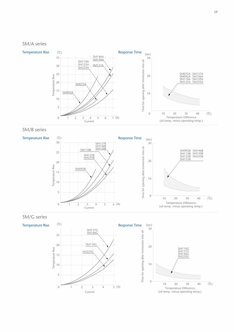
seTemperature Rise
Temperature Rise
Temperature Rise
Response Time
Response Time
Response Time
SM/A series
SM/B series
SM/G series
30
25
20
15
10
5
0 2 4 61 3 5
(℃)
(A)Current
SM092B
SM110B
SM225BSM125B
SM146BSM137B
SM150B
Tem
per
atur
e Ri
se
(℃)
(sec)
SM225B
SM146B
SM137B
SM110BSM092B
SM125B
30
20
10
010 20 30 40
SM150B
Temperature Difference(oil temp. minus operating temp.)
Tim
e fo
r op
enin
g af
ter
imm
ersi
on in
to o
il
(℃)
(A)
Current
Tem
per
atur
e Ri
se
25
20
15
10
5
0 2 41 3 5
SM137GSM146G
SM110G
SM225G
Temperature Difference(oil temp. minus operating temp.)
Tim
e fo
r op
enin
g af
ter
imm
ersi
on in
to o
il
(℃)
(sec)30
20
10
010 20 30 40
SM225G
SM110GSM137GSM146G
18
Definition of Terms
Rated Functioning Temperature (Tf)Rated functioning temperature is the operating temperature of the thermal link, measured using the method specified in the safety standard.As stated in the Electrical Appliance and Material Safety Law (PSE) of Japan (Appendix 3, Section 3), the thermal links should operate within ±7°C of the specified operating temperature. In cases where Tf is greater than 200°C, the thermal links should operate within ±10°C of the specified operating temperature.In standards that comply with the IEC standard, it is indicated that the thermal links should operate within +0/-10°C of the specified temperature range.
Operating TemperatureOperating temperature and tolerance refers to the operating temperature range measured by the following conditions.A thermal link test sample is placed in the condition where the temperature of a thermostatic oven is raised until 12°C belowthe rated functioning temperature of the test sample at optionally increasing speed.Then the temperature of the thermostatic oven is raised at the rate of 0.5-1.0°C a minute.At this time, the electric current flowing through the test sample for opening confirmation shall be less than 10mA.Furthermore, the distance between a measuring point and a test sample shall be less than 20 mm.
Th (Holding Temperature)Th is the maximum temperature measured on the thermal links when it continues to conduct a rated current without changing its state of conductivity for 168 hours.
Tm (Maximum Temperature Limit)Maximum temperature limit is the maximum temperature for which conductivity does not occur again during the following test.First, the samples are maintained at Tm for a period of 10 minutes. Then, the withstand voltage test is conducted for 2 minutes with twice the rated voltage. During the test, the thermal links must remain in the functioned state, i.e. open. Hence, no current is allowed to pass through.(Functioned state of the SF-type: not less than 0.2MΩ; SM-type: not less than 2MΩ (between body and lead) and not less than 0.2MΩ (between lead and lead)
Lead Cutting and Taping
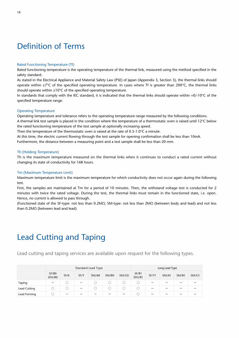
Lead cutting and taping services are available upon request for the following types.
Standard Lead Type Long Lead Type
SF/R0SFH/R0
SF/K SF/Y SM/A0 SM/B0 SM/G0SF/R1
SFH/R1SF/Y1 SM/A1 SM/B1 SM/G1
Taping - ○ - ○ ○ ○ ○ - - - -
Lead Cutting ○ ○ - ○ ○ ○ ○ - - - -
Lead Forming ○ - - - - - ○ - - - -
19
L1 L2
R
S T W
t
T
S
ZP
R
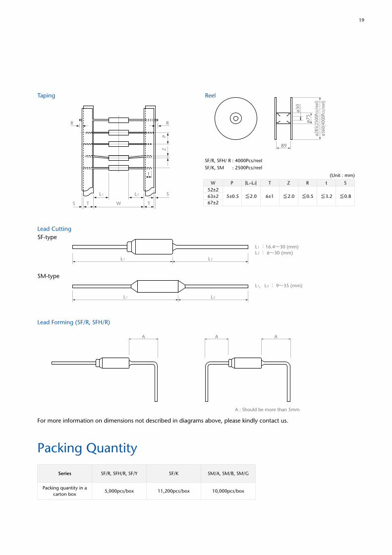
Taping Reel
Lead Cutting
Lead Forming (SF/R, SFH/R)
Packing Quantity
SF/R, SFH/ R : 4000Pcs/reelSF/K, SM : 2500Pcs/reel
ø30
ø75
89
(Unit : mm)
ø285
(250
0Pcs
/ree
l)ø3
60(4
000P
cs/r
eel)
W P T Z R t S|L1-L2|52±2
5±0.5 6±1≦2.0 ≦2.0 ≦0.5 ≦3.2 ≦0.863±267±2
SF-type
SM-type
L1 L2
L1 L2
L1 :16.4~30 (mm)L2 : 6~30 (mm)
L1, L2 : 9~35 (mm)
片側折り曲げ 両側折り曲げ
A : Should be more than 5mm
AAA
For more information on dimensions not described in diagrams above, please kindly contact us.
Series SF/R, SFH/R, SF/Y SF/K SM/A, SM/B, SM/G
Packing quantity in a carton box
5,000pcs/box 11,200pcs/box 10,000pcs/box
20
Cautions
This section describes points to note, about the design, installation and storage of SEFUSE® thermal links, so as to achieve the optimum performance of these thermal protection devices.
For optimal thermal link performance, it is recommended that customers correctly store the thermal protection devices, design appropriate circuits for the appliances and perform evaluations, mounting and testing steps as necessary. Problems arising from the inappropriate execution of the above would be the sole responsibility of the customer, and SCHOTT declines any and all responsibility.
Design
Do not use this device for any purpose other than as a thermal link.The thermal link is designed to detect abnormal rises in temperature and open the electrical circuits as required. It is not a current fuse that cuts off excess current. If the thermal link is used as a current fuse, it may malfunction.
Do not use this device in aerospace equipment, aeronautical equipment, nuclear reactor control systems, life support equipment or systems, transportation machinery engine control or safety-related equipment.This device is designed for use in household electrical appliances, office automation equipment, audio and video equipment, computer communications equipment, test and measurement equipment, personal electronic equipment and transportation equipment (excluding engine control).
Decisions regarding the type of thermal link, the installation location and the mounting method should be made by the customers, based upon the requirements of the final application.It is recommended that designers test the final design with the selected thermal link under both normal conditions as well as predicted worst-case scenarios.
▼Thermal links should be mounted where it can detect abnormal heat as quickly as possible.The thermal link operates when the thermal element within melts. Therefore, if the thermal element does not reach the operating temperature, the cutoff will not activate even if the ambient temperature has risen to the operating temperature. In addition, a short lag time might result in the event of a sudden rise in the ambient temperature or if the thermal link only detects part of the temperature increase.
▼Thermal links* should be mounted such that the temperature gradient is equal throughout the thermal link.If lead B of the SF-type, which is caulked to the metal case, is mounted in such a way that it only conducts heat to the metal case, the temperature around the thermal pellet would always be higher than other parts in the metal case. This could lead to the thermal link opening prematurely. Hence, it is recommended that lead A, which is the resin-sealed side, be connected nearer to the heat source.It should also be mentioned that similarly, if lead A is fixed in a location where the temperature it is exposed to is always lower than that of lead B, the thermal link could also be prematurely triggered.* except SFH/R series
▼Cautions about TmPlease ensure that the design of the final application does not exceed Tm (the maximum temperature limit) of the thermal link.If used in conditions beyond the rated temperature, a dielectric breakdown could result and the thermal link could re- conduct even after opening.
▼Cautions about Th (SF-type)Continuous exposure to temperatures close to the Th temperature of the thermal link could result in the thermal pellet reducing in size over time, thereby shortening the lifespan of the thermal link. This change in the pellet size is irreversible. Hence, it is important that designers select and test thermal links suitable for the temperature zone of the final application, based on the temperature recommendations in Table 1.Please also note that the Th temperature test is a one-time test, not a cycle test, conducted continuously for 168 hours.
21
Designers of the final application should take into account the maximum surface temperature of the thermal link as shown in Table 1, and avoid exceeding this level.If the body temperature of the thermal link is exceeded on a regular basis, the thermal link may start opening at temperatures lower than the normal operating temperature. Malfunctions may also occur. In case of using SM-type in DC rating, please kindly contact SCHOTT.
Thermal links have a limited life.The thermal elements used are durable substances designed for long-term use. However, the longevity of the thermal link depends on the conditions in which it is exposed to. This is particularly true if the thermal protection device is frequently exposed to temperatures very close to its operating temperature.Hence, it is recommended that designers conduct a reliability test by fixing the thermal protection device onto the actual application and simulating the expected operating conditions to assess the lifetime of the device.
The body temperature of the thermal link increases as current passes through it.The body temperature of the thermal link could rise to levels higher than the ambient temperature current passes through the device. In addition, the body temperature could also increase depending on a number of factors such as the mounting method. Hence, it is recommended that designers measure the body temperature of the thermal link after conducting a reliability test.
Use the thermal link with a voltage and current level lower than the rated level.If the thermal link is used with a voltage or current level higher than the rated level, the contacts may be welded together in the SF-type, causing the thermal link to malfunction. In the SM-type, the body of the thermal link may rupture.
Do not use the thermal link in an atmosphere out of the standard specifications such as in environments exposed to sulfurous acid gas, nitrogen oxide gas, ammonia gas or conditions that contain formic acid. It is also not suitable for high humidity situations and submersion in a liquid.The case of the thermal link* is made with a copper alloy. Hence, installing the thermal link in such conditions or similar, could deteriorate the sealing resin or lead to cracks in the case of the thermal link due to corrosion. The thermal link could thus operate at lower than operating temperatures or not activate even if its operating temperature is exceeded.* SF-K series only
The thermal link corresponds to industrial waste.The thermal link corresponds to industrial waste, and requires disposal according to governmental and provincial regulations. The services of a licensed disposal contractor could also be engaged.
The thermal link is a non-repairable device.In case of replacement, an equivalent thermal link from the same manufacturer should be used. For general consumers who are not aware of the cautions associated with the thermal link, they should be informed not to mount, remove or replace the thermal link through a note to this effect in the user's manual and other related materials.
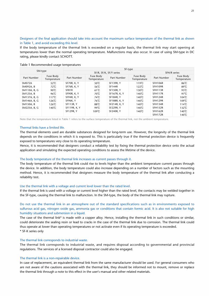
Table 1 Recommended usage temperatures
SM-typeSF-type
SF/R, SF/K, SF/Y series SFH/R series
Note that the temperature listed in Table 1 refers to the surface temperature of the thermal link, not the ambient temperature.
SM072ASM092A, BSM110A, B, GSM125A, BSM137A, B, GSM146A, B, GSM150A, BSM225A, B, G
Part NumberFuse Body
Temperature Part NumberFuse Body
Temperature Part NumberFuse Body
Temperature Part NumberFuse Body
Temperature
52℃72℃90℃96℃
117℃126℃126℃140℃
50℃56℃61℃70℃74℃76℃88℃99℃
109℃
119℃122℃130℃140℃140℃140℃140℃140℃140℃
86℃89℃93℃97℃
104℃109℃114℃132℃140℃140℃
SF70R, K, YSF76R, K, YSF81RSF90R, K, YSF94R, K, YSF96K, YSF113R, YSF119R, K, YSF129R, Y
SF139R, YSF144RSF150R, YSF167R, K, YSF184R, YSF188R, K, YSF214R, K, YSF229R, YSF240R, Y
SFH106RSFH109RSFH113RSFH117RSFH124RSFH129RSFH134RSFH152RSFH162RSFH172R
22
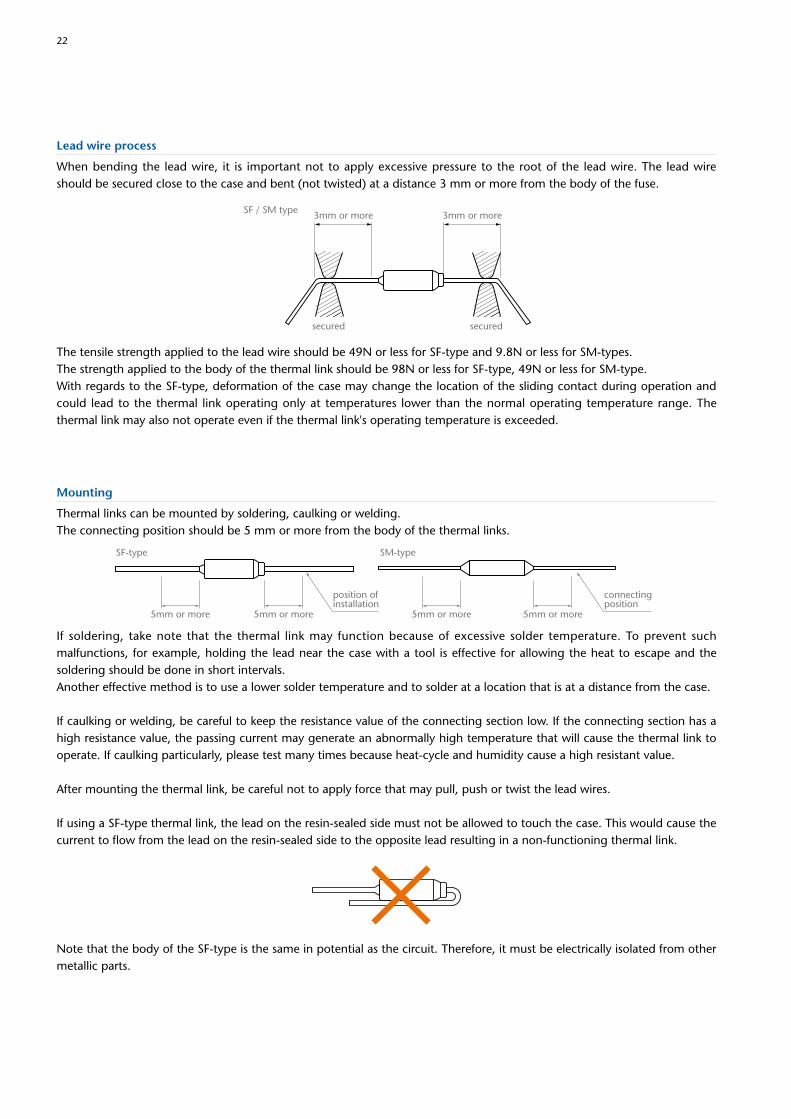
Lead wire process
5mm or more5mm or more 5mm or more5mm or more
SF-type SM-type
connectingposition
position ofinstallation
Mounting
Thermal links can be mounted by soldering, caulking or welding.The connecting position should be 5 mm or more from the body of the thermal links.
secured secured
3mm or more3mm or moreSF / SM type
When bending the lead wire, it is important not to apply excessive pressure to the root of the lead wire. The lead wire should be secured close to the case and bent (not twisted) at a distance 3 mm or more from the body of the fuse.
The tensile strength applied to the lead wire should be 49N or less for SF-type and 9.8N or less for SM-types.The strength applied to the body of the thermal link should be 98N or less for SF-type, 49N or less for SM-type.With regards to the SF-type, deformation of the case may change the location of the sliding contact during operation and could lead to the thermal link operating only at temperatures lower than the normal operating temperature range. The thermal link may also not operate even if the thermal link's operating temperature is exceeded.
If soldering, take note that the thermal link may function because of excessive solder temperature. To prevent such malfunctions, for example, holding the lead near the case with a tool is effective for allowing the heat to escape and the soldering should be done in short intervals.Another effective method is to use a lower solder temperature and to solder at a location that is at a distance from the case.
If caulking or welding, be careful to keep the resistance value of the connecting section low. If the connecting section has a high resistance value, the passing current may generate an abnormally high temperature that will cause the thermal link to operate. If caulking particularly, please test many times because heat-cycle and humidity cause a high resistant value.
After mounting the thermal link, be careful not to apply force that may pull, push or twist the lead wires.
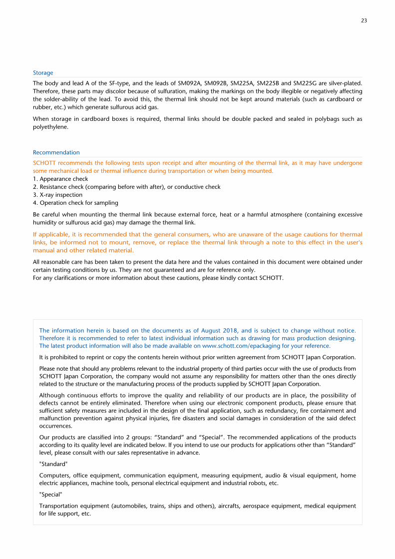
If using a SF-type thermal link, the lead on the resin-sealed side must not be allowed to touch the case. This would cause the current to flow from the lead on the resin-sealed side to the opposite lead resulting in a non-functioning thermal link.
Note that the body of the SF-type is the same in potential as the circuit. Therefore, it must be electrically isolated from other metallic parts.
2 23
Storage
The body and lead A of the SF-type, and the leads of SM092A, SM092B, SM225A, SM225B and SM225G are silver-plated. Therefore, these parts may discolor because of sulfuration, making the markings on the body illegible or negatively affecting the solder-ability of the lead. To avoid this, the thermal link should not be kept around materials (such as cardboard or rubber, etc.) which generate sulfurous acid gas.
When storage in cardboard boxes is required, thermal links should be double packed and sealed in polybags such as polyethylene.
Recommendation
SCHOTT recommends the following tests upon receipt and after mounting of the thermal link, as it may have undergone some mechanical load or thermal influence during transportation or when being mounted.1. Appearance check2. Resistance check (comparing before with after), or conductive check3. X-ray inspection4. Operation check for sampling
Be careful when mounting the thermal link because external force, heat or a harmful atmosphere (containing excessive humidity or sulfurous acid gas) may damage the thermal link.
If applicable, it is recommended that the general consumers, who are unaware of the usage cautions for thermal links, be informed not to mount, remove, or replace the thermal link through a note to this effect in the user's manual and other related material.
All reasonable care has been taken to present the data here and the values contained in this document were obtained under certain testing conditions by us. They are not guaranteed and are for reference only.For any clarifications or more information about these cautions, please kindly contact SCHOTT.
The information herein is based on the documents as of August 2018, and is subject to change without notice. Therefore it is recommended to refer to latest individual information such as drawing for mass production designing. The latest product information will also be made available on www.schott.com/epackaging for your reference.
It is prohibited to reprint or copy the contents herein without prior written agreement from SCHOTT Japan Corporation.
Please note that should any problems relevant to the industrial property of third parties occur with the use of products from SCHOTT Japan Corporation, the company would not assume any responsibility for matters other than the ones directly related to the structure or the manufacturing process of the products supplied by SCHOTT Japan Corporation.
Although continuous efforts to improve the quality and reliability of our products are in place, the possibility of defects cannot be entirely eliminated. Therefore when using our electronic component products, please ensure that sufficient safety measures are included in the design of the final application, such as redundancy, fire containment and malfunction prevention against physical injuries, fire disasters and social damages in consideration of the said defect occurrences.
Our products are classified into 2 groups: “Standard” and “Special”. The recommended applications of the products according to its quality level are indicated below. If you intend to use our products for applications other than “Standard” level, please consult with our sales representative in advance.
"Standard"
Computers, office equipment, communication equipment, measuring equipment, audio & visual equipment, home electric appliances, machine tools, personal electrical equipment and industrial robots, etc.
"Special"
Transportation equipment (automobiles, trains, ships and others), aircrafts, aerospace equipment, medical equipment for life support, etc.
SCHOTT is a leading international technology group in the areas of specialty glass and glass-ceramics. With more than 130 years of outstanding development, materials and technology expertise we offer a broad portfolio of high-quality products and intelligent solutions that contribute to our customers’ success.For several decades, SCHOTT has been a leading developer and manufacturer of thermal links. These safety devices serve a broad range of applications, including home appliances, li-ion batteries and automobiles. With many years of extensive experience and a strong development and manufacturing set-up, we can respond flexibly to market needs and customer requirements.
SEFUSE®
Thermal Links
SCHOTT Japan Corporation3-1 Nichiden, Minakuchi-cho, Koka-shi, Shiga 528-0034, JapanPhone +81-(0)748-63-6629Fax +81-(0)[email protected]/epackaging
70219 ENGLISH 08/2018 Printed in Japan
This printed matter uses FSC® certified paper using properly controlled forest
wood. Furthermore, it uses vegetable-oil-based ink including soy oil-based ink
and waterless printing that does not discharge any hazardous waste fluids.