Embed Size (px)
Citation preview

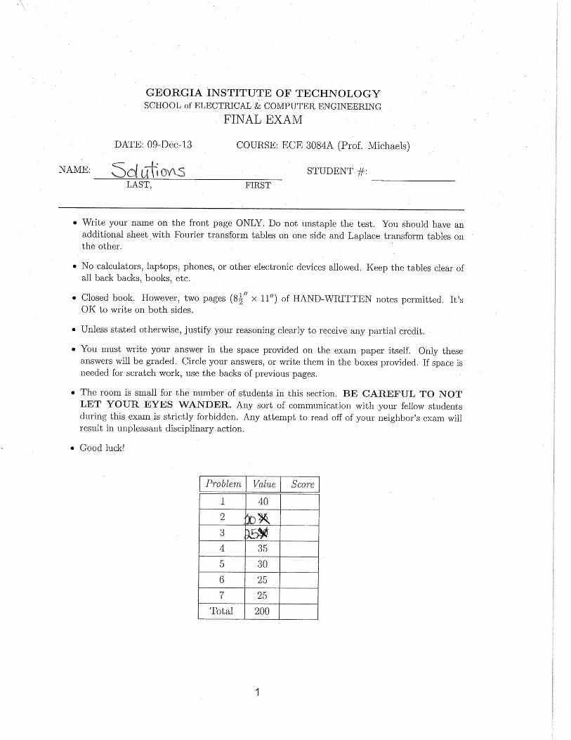
GEORGIA INSTITUTE OF TECHNOLOGYSCHOOL of ELECTRICAL & COMPUTER ENGINEERING
FINAL EXAM
DATE: 09-Dec-13 COURSE: ECE 3084A (Prof. Michaels)
NAME: STUDENT #:
LAST, FIRST
• Write your name on the front page ONLY. Do not unstaple the test. You should have anadditional sheet with Fourier transform tables on one side and Laplace transform tables onthe other.
• No calculators, laptops, phones, or other electronic devices allowed. Keep the tables clear ofall back backs, books, etc.
• Closed book. However, two pages (812
′′ × 11′′) of HAND-WRITTEN notes permitted. It’sOK to write on both sides.
• Unless stated otherwise, justify your reasoning clearly to receive any partial credit.
• You must write your answer in the space provided on the exam paper itself. Only theseanswers will be graded. Circle your answers, or write them in the boxes provided. If space isneeded for scratch work, use the backs of previous pages.
• The room is small for the number of students in this section. BE CAREFUL TO NOTLET YOUR EYES WANDER. Any sort of communication with your fellow studentsduring this exam is strictly forbidden. Any attempt to read off of your neighbor’s exam willresult in unpleasant disciplinary action.
• Good luck!
Problem Value Score
1 40
2 25
3 20
4 35
5 30
6 25
7 25
Total 200
1

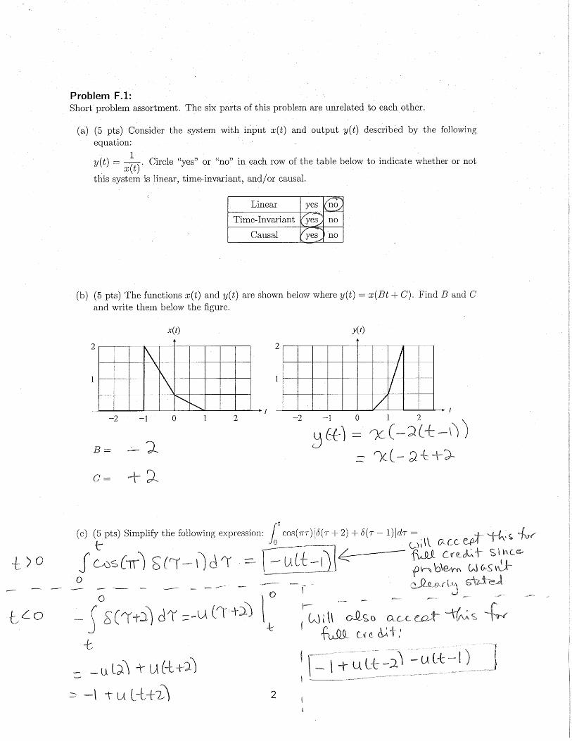
Problem F.1:Short problem assortment. The six parts of this problem are unrelated to each other.
(a) (5 pts) Consider the system with input x(t) and output y(t) described by the followingequation:
y(t) =1
x(t). Circle “yes” or “no” in each row of the table below to indicate whether or not
this system is linear, time-invariant, and/or causal.
Linear yes no
Time-Invariant yes no
Causal yes no
(b) (5 pts) The functions x(t) and y(t) are shown below where y(t) = x(Bt+C). Find B and Cand write them below the figure.
0 1 2 −2 −1
1
2
0 1 2 −2 −1
1
2
x(t) y(t)
t t
B =
C =
(c) (5 pts) Simplify the following expression:
∫ t
0cos(πτ)[δ(τ + 2) + δ(τ − 1)]dτ =
2
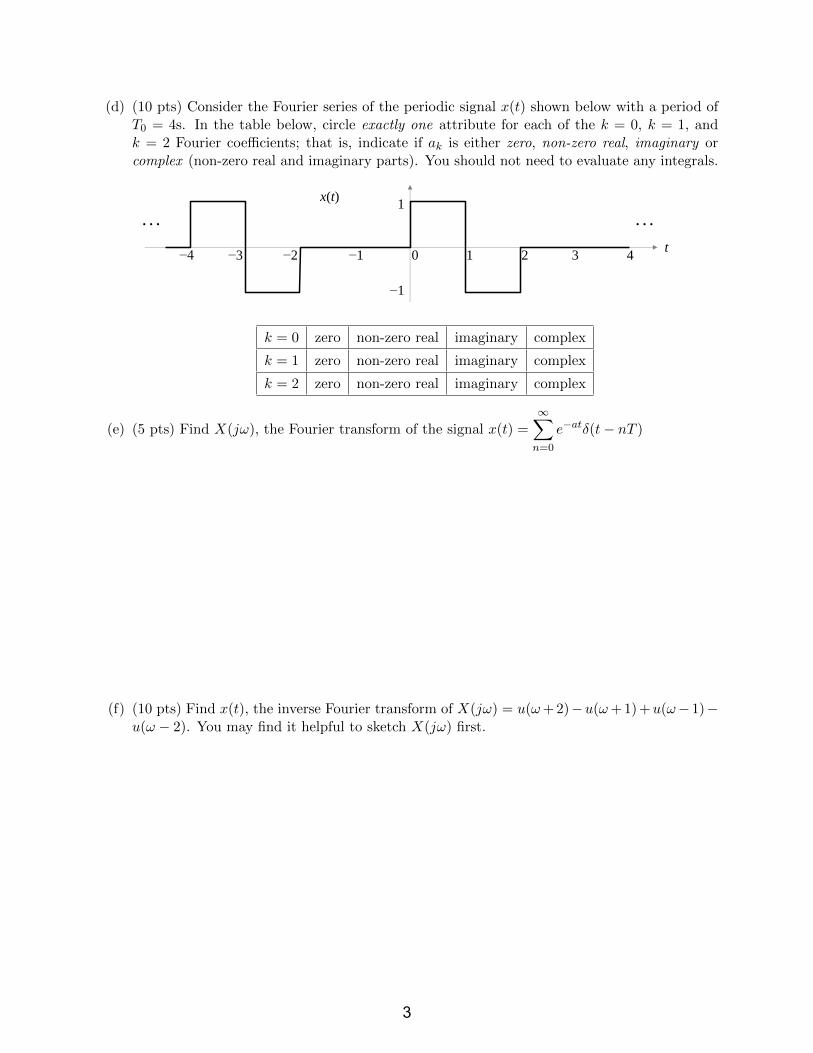
(d) (10 pts) Consider the Fourier series of the periodic signal x(t) shown below with a period ofT0 = 4s. In the table below, circle exactly one attribute for each of the k = 0, k = 1, andk = 2 Fourier coefficients; that is, indicate if ak is either zero, non-zero real, imaginary orcomplex (non-zero real and imaginary parts). You should not need to evaluate any integrals.
0 1 2 −2 −1 3 4 −3 −4
1
−1
x(t)
t
. . . . . .
k = 0 zero non-zero real imaginary complex
k = 1 zero non-zero real imaginary complex
k = 2 zero non-zero real imaginary complex
(e) (5 pts) Find X(jω), the Fourier transform of the signal x(t) =
∞∑n=0
e−atδ(t− nT )
(f) (10 pts) Find x(t), the inverse Fourier transform of X(jω) = u(ω+ 2)−u(ω+ 1) +u(ω− 1)−u(ω − 2). You may find it helpful to sketch X(jω) first.
3

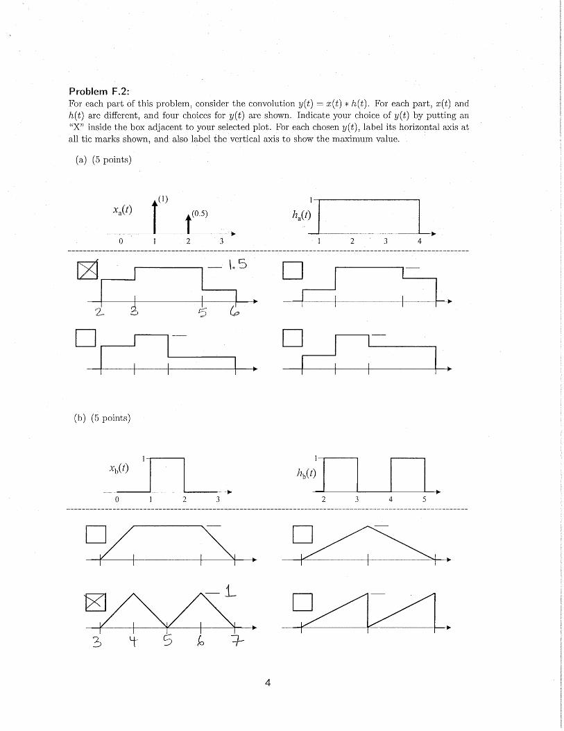
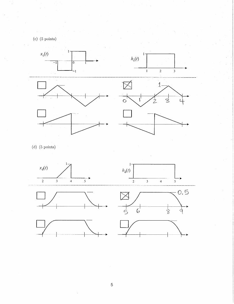
Problem F.2:For each part of this problem, consider the convolution y(t) = x(t) ∗ h(t). For each part, x(t) andh(t) are different, and four choices for y(t) are shown. Indicate your choice of y(t) by putting an“X” inside the box adjacent to your selected plot. For each chosen y(t), label its horizontal axis atall tic marks shown, and also label the vertical axis to show the maximum value.
(a) (5 points)
0 1 2 3
xa(t) (1)
(0.5)
1 2 3 4
ha(t)
1
(b) (5 points)
0 1 2 3
xb(t)
2 3 4 5
hb(t)
1 1
4
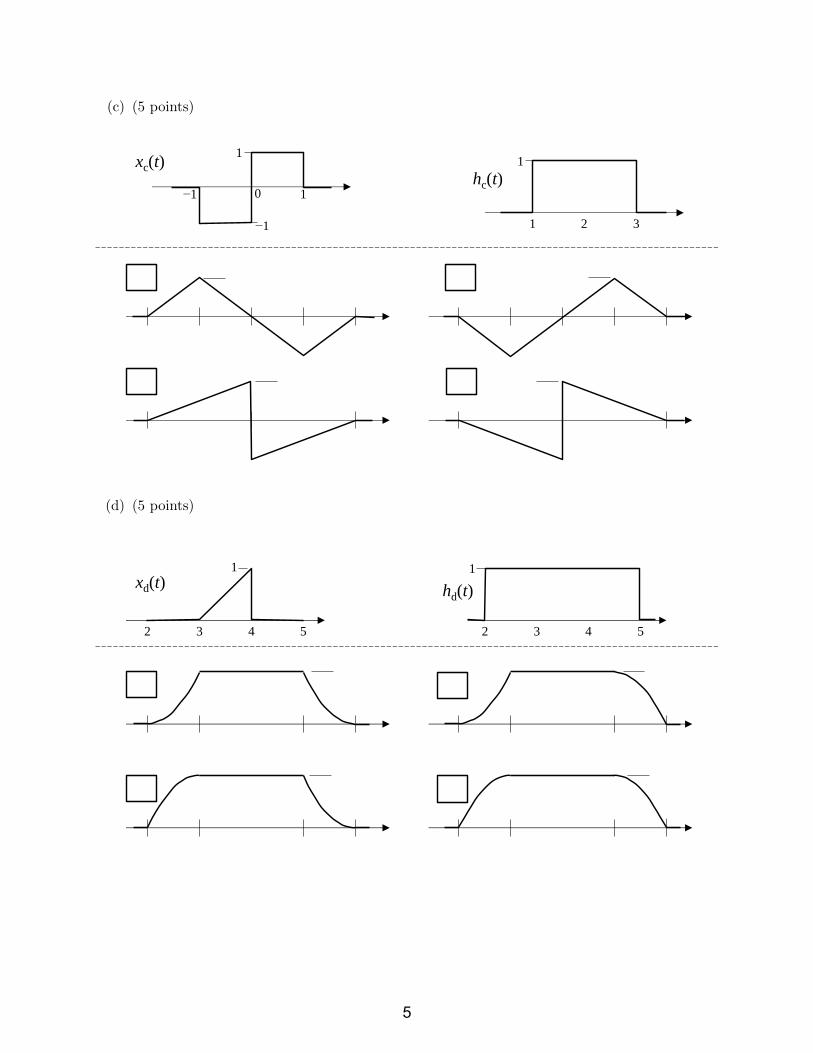
(c) (5 points)
−1 0 1
xc(t) 1
−1 1 2 3
hc(t) 1
(d) (5 points)
2 3 4 5
xd(t)
2 3 4 5
hd(t)
1 1
5

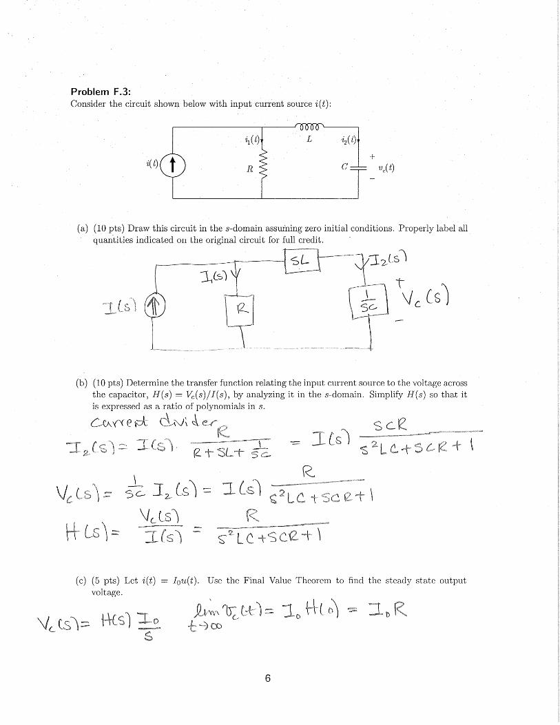
Problem F.3:Consider the circuit shown below with input current source i(t):
R
L
C i(t)
i1(t) i2(t)
+
−
vc(t)
(a) (10 pts) Draw this circuit in the s-domain assuming zero initial conditions. Properly label allquantities indicated on the original circuit for full credit.
(b) (10 pts) Determine the transfer function relating the input current source to the voltage acrossthe capacitor, H(s) = Vc(s)/I(s), by analyzing it in the s-domain. Simplify H(s) so that itis expressed as a ratio of polynomials in s.
(c) (5 pts) Let i(t) = I0u(t). Use the Final Value Theorem to find the steady state outputvoltage.
6

Problem F.4:Consider a system with input x(t) and output y(t) whose impulse response is h(t) = δ(t)+δ(t− td).This system is a reasonable model for a signal with an echo (often called “multipath”) where td,the time delay of the echo, is unknown.
(a) (10 pts) Find H(jω) in terms of td. Simplify it as much as possible, which will help you withpart (c).
(b) (10 pts) Find y(t) for td = 4 and x(t) = 5 + u(t)− u(t− 1) + 2 cos(π2 t).
7

(c) (10 pts) Accurately sketch |H(jω)| for |ω| < 6π/td.
(d) (5 pts) One strategy for finding td is to excite the system with a delta function; i.e., x(t) = δ(t),and analyze the response y(t) in the frequency domain by finding its nulls (frequencies whereY (jω) = 0). Express td in terms of ωnull, the first null of Y (jω), for x(t) = δ(t). (This shouldbe very straightforward if part (c) is correct).
8
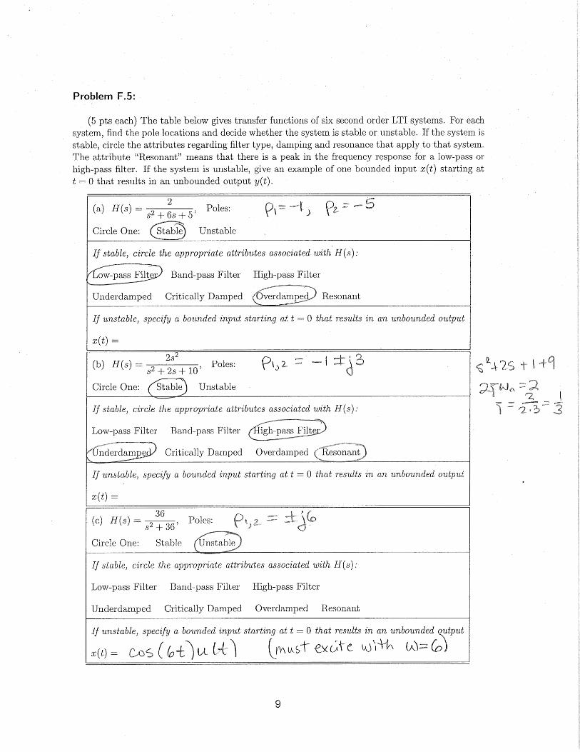
Problem F.5:
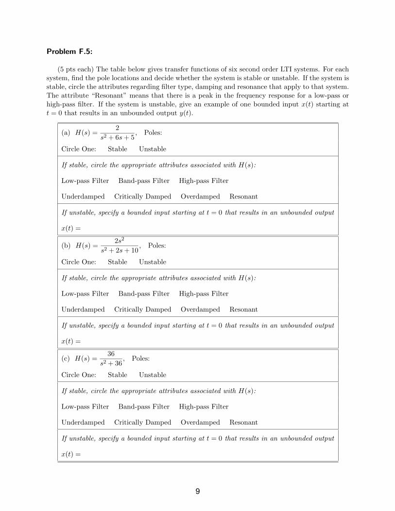
(5 pts each) The table below gives transfer functions of six second order LTI systems. For eachsystem, find the pole locations and decide whether the system is stable or unstable. If the system isstable, circle the attributes regarding filter type, damping and resonance that apply to that system.The attribute “Resonant” means that there is a peak in the frequency response for a low-pass orhigh-pass filter. If the system is unstable, give an example of one bounded input x(t) starting att = 0 that results in an unbounded output y(t).
(a) H(s) =2
s2 + 6s+ 5, Poles:
Circle One: Stable Unstable
If stable, circle the appropriate attributes associated with H(s):
Low-pass Filter Band-pass Filter High-pass Filter
Underdamped Critically Damped Overdamped Resonant
If unstable, specify a bounded input starting at t = 0 that results in an unbounded output
x(t) =
(b) H(s) =2s2
s2 + 2s+ 10, Poles:
Circle One: Stable Unstable
If stable, circle the appropriate attributes associated with H(s):
Low-pass Filter Band-pass Filter High-pass Filter
Underdamped Critically Damped Overdamped Resonant
If unstable, specify a bounded input starting at t = 0 that results in an unbounded output
x(t) =
(c) H(s) =36
s2 + 36, Poles:
Circle One: Stable Unstable
If stable, circle the appropriate attributes associated with H(s):
Low-pass Filter Band-pass Filter High-pass Filter
Underdamped Critically Damped Overdamped Resonant
If unstable, specify a bounded input starting at t = 0 that results in an unbounded output
x(t) =
9

(d) H(s) =20s
s2 + 10s+ 25, Poles:
Circle One: Stable Unstable
If stable, circle the appropriate attributes associated with H(s):
Low-pass Filter Band-pass Filter High-pass Filter
Underdamped Critically Damped Overdamped Resonant
If unstable, specify a bounded input starting at t = 0 that results in an unbounded output
x(t) =
(e) H(s) =s2
s2 + 4s− 5, Poles:
Circle One: Stable Unstable
If stable, circle the appropriate attributes associated with H(s):
Low-pass Filter Band-pass Filter High-pass Filter
Underdamped Critically Damped Overdamped Resonant
If unstable, specify a bounded input starting at t = 0 that results in an unbounded output
x(t) =
(f) H(s) =100
s2 + 8s+ 25, Poles:
Circle One: Stable Unstable
If stable, circle the appropriate attributes associated with H(s):
Low-pass Filter Band-pass Filter High-pass Filter
Underdamped Critically Damped Overdamped Resonant
If unstable, specify a bounded input starting at t = 0 that results in an unbounded output
x(t) =
10

Problem F.6:This problem considers velocity control of a plant Gp(s) using a controller Gc(s) where Gc(s) = Kp
(proportional control) and Gp(s) =1
s(s+ a).
+
−
R(s) Y(s) Gc(s) Gp(s)
(a) (5 pts) Find the transfer function H(s) of the closed loop system in terms of a, the plant polelocation, and Kp. Express your answer as a ratio of polynomials with all like terms combined.
(b) (10 pts) For Kp > 0 and a > 0, indicate whether the following statements about the closedloop system are true or false. Select “Can’t Tell” if there is insufficient information to deter-mine if it is true or false.
The system is stable for all Kp > 0 and a > 0 True False Can’t Tell
The system perfectly tracks a step function input True False Can’t Tell
The system is overdamped True False Can’t Tell
The natural frequency ωn depends only on Kp True False Can’t Tell
The damping ratio ζ depends only on a True False Can’t Tell
(c) (10 pts) Consider the case where a = 10. Find Kp such that ζ = 5/6. Where are the poles ofthe resulting closed loop system?
11

Problem F.7:
Consider the feedback system shown below, which differs from that of the previous problemby having positive feedback (see the positive sign where y(t) feeds into the summing junction).
The transfer function of a closed loop system with positive feedback is H+(s) =Gc(s)Gp(s)
1−Gc(s)Gp(s).
Positive feedback is usually undesirable, but it is often quite easy to accidentally hook up a systemincorrectly such that the feedback is positive rather than negative (Prof. Michaels knows thisfrom personal experience). As for the previous problem, consider the situation for which the plantoutput, y(t), is the velocity of a mechanical system, and the goal is to control velocity.
+
+
R(s) Y(s) Gc(s) Gp(s)
(a) (5 pts) Find the transfer function H+(s) of the closed loop system with positive feedback for
Gc(s) = Kp (proportional control) and Gp(s) =1
s(s+ a). Express your answer as a ratio of
polynomials with all like terms combined.
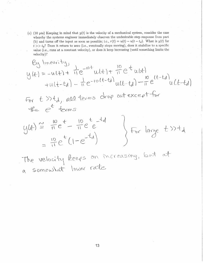
(b) (10 pts) For a = 9 and Kp = 10, find the complete step response; that is, find y(t) forr(t) = u(t).
12

(c) (10 pts) Keeping in mind that y(t) is the velocity of a mechanical system, consider the casewhereby the systems engineer immediately observes the undesirable step response from part(b) and turns off the input as soon as possible; i.e., r(t) = u(t)− u(t− td). What is y(t) fort >> td? Does it return to zero (i.e., eventually stops moving), does it stabilize to a specificvalue (i.e., runs at a constant velocity), or does it keep increasing (until something limits thevelocity)?
13


![IgY JoVE Protocol 3084[1]](https://img.pdfslide.us/doc/110x75/577d242a1a28ab4e1e9bc162/igy-jove-protocol-30841.jpg)