Embed Size (px)
Citation preview
The Scholastic SeriesSchool Bus Heater
Operating InstructionsInstallation InstructionsService Parts Listing
Webasto Thermosystems Inc.North America3333 John Conley DriveLapeer, MI 48446Phone (810) 245-2400Toll-free (800) HEATER-1Fax (810) 664-7720
Technical Assistance HotlineUSA: (800) 555-4518Canada: (800) 667-8900
www.webasto.comOrg. 2/2001 50000058A
For:
Conventional ModelTransit Model (Engine Front)Transit Model (Engine Rear)
TABLE OF CONTENTS
I
Table of Contents
1. Introduction
1.1 Scope and Purpose . . . . . . . . . . . . . . . . . . . . . . . . . . . . . . . . . . . . . . . . . . . . . . . . . . . . 1-11.2 Meaning of Warnings, Cautions and Notes . . . . . . . . . . . . . . . . . . . . . . . . . . . . . . . . . . 1-11.3 Additional Documentation to be Used . . . . . . . . . . . . . . . . . . . . . . . . . . . . . . . . . . . . . . 1-11.4 General Safety Regulations and Information . . . . . . . . . . . . . . . . . . . . . . . . . . . . . . . . . 1-1
1.4.1 General Safety Notes . . . . . . . . . . . . . . . . . . . . . . . . . . . . . . . . . . . . . . . . . . . 1-1
2. General Description
2.1 Scholastic Heater Description . . . . . . . . . . . . . . . . . . . . . . . . . . . . . . . . . . . . . . . . . . . . 2-1
3. Functional Description
3.1 Operating your Webasto Scholastic Heater . . . . . . . . . . . . . . . . . . . . . . . . . . . . . . . . . . 3-13.2 Switching On . . . . . . . . . . . . . . . . . . . . . . . . . . . . . . . . . . . . . . . . . . . . . . . . . . . . . . . . . 3-13.3 Switching Off . . . . . . . . . . . . . . . . . . . . . . . . . . . . . . . . . . . . . . . . . . . . . . . . . . . . . . . . . 3-23.4 Engine Preheating . . . . . . . . . . . . . . . . . . . . . . . . . . . . . . . . . . . . . . . . . . . . . . . . . . . . . 3-23.5 Boost Heating for Engine and Passenger Compartment . . . . . . . . . . . . . . . . . . . . . . . . . 3-23.6 Operation with 7-Day Digital Timer Model 1531 . . . . . . . . . . . . . . . . . . . . . . . . . . . . . . . 3-23.7 7-Day Digital Timer Programming and Operating Instructions . . . . . . . . . . . . . . . . . . . . . 3-4
4. Technical Data
4.1 Scholastic Series Heater Data . . . . . . . . . . . . . . . . . . . . . . . . . . . . . . . . . . . . . . . . . . . . 4-1
4.1.1 Scholastic Series Heater Dimensions . . . . . . . . . . . . . . . . . . . . . . . . . . . . . . . 4-2
4.2 Coolant Circulation Pump Data . . . . . . . . . . . . . . . . . . . . . . . . . . . . . . . . . . . . . . . . . . . 4-3
4.2.1 Coolant Circulation Pump Dimensions . . . . . . . . . . . . . . . . . . . . . . . . . . . . . . . 4-3
4.3 Tray Mount Dimensions . . . . . . . . . . . . . . . . . . . . . . . . . . . . . . . . . . . . . . . . . . . . . . . . . 4-4
5. Installation
5.1 General Information . . . . . . . . . . . . . . . . . . . . . . . . . . . . . . . . . . . . . . . . . . . . . . . . . . . . 5-15.2 Installation Locations . . . . . . . . . . . . . . . . . . . . . . . . . . . . . . . . . . . . . . . . . . . . . . . . . . . 5-15.3 Mounting the Heater . . . . . . . . . . . . . . . . . . . . . . . . . . . . . . . . . . . . . . . . . . . . . . . . . . . 5-25.4 Exhaust Pipe Connection . . . . . . . . . . . . . . . . . . . . . . . . . . . . . . . . . . . . . . . . . . . . . . . 5-25.5 Combustion Air Supply . . . . . . . . . . . . . . . . . . . . . . . . . . . . . . . . . . . . . . . . . . . . . . . . . 5-35.6 Plumbing into the Coolant System . . . . . . . . . . . . . . . . . . . . . . . . . . . . . . . . . . . . . . . . . 5-3
5.6.1 General Information . . . . . . . . . . . . . . . . . . . . . . . . . . . . . . . . . . . . . . . . . . . . . 5-35.6.2 Engine and Passenger Compartment Heating . . . . . . . . . . . . . . . . . . . . . . . . . 5-45.6.3 Instructions for Integrating into the Coolant System . . . . . . . . . . . . . . . . . . . . . 5-5
WEBASTO SCHOLASTIC SERIES
TABL E OF CONTENTS WEBASTO SCHOLASTIC SERIES
II
5.7 Fuel System . . . . . . . . . . . . . . . . . . . . . . . . . . . . . . . . . . . . . . . . . . . . . . . . . . . . . . . . . 5-7
5.7.1 General Description . . . . . . . . . . . . . . . . . . . . . . . . . . . . . . . . . . . . . . . . . . . . . 5-75.7.2 Fuel Supply . . . . . . . . . . . . . . . . . . . . . . . . . . . . . . . . . . . . . . . . . . . . . . . . . . . 5-75.7.3 Fuel Filter . . . . . . . . . . . . . . . . . . . . . . . . . . . . . . . . . . . . . . . . . . . . . . . . . . . . 5-9
5.8 Wiring Connections . . . . . . . . . . . . . . . . . . . . . . . . . . . . . . . . . . . . . . . . . . . . . . . . . . . . 5-10
5.8.1 General Information . . . . . . . . . . . . . . . . . . . . . . . . . . . . . . . . . . . . . . . . . . . . . 5-105.8.2 Connecting Power Harness to a Constant Power Source . . . . . . . . . . . . . . . . . 5-105.8.3 Timer and Switch Connections . . . . . . . . . . . . . . . . . . . . . . . . . . . . . . . . . . . . 5-115.8.4 Timer and Switch Installation . . . . . . . . . . . . . . . . . . . . . . . . . . . . . . . . . . . . . . 5-115.8.5 Wiring Diagram - Scholastic Series Heater . . . . . . . . . . . . . . . . . . . . . . . . . . . 5-125.8.6 Wiring Diagram - Chassis / Power Harness with Switch . . . . . . . . . . . . . . . . . . 5-135.8.7 Wiring Diagram - Chassis / Power Harness with Switch . . . . . . . . . . . . . . . . . . 5-145.8.8 Wiring Diagram - Chassis / Power Harness with Digital Timer Model 1531 . . . . 5-155.8.9 Wiring Diagram - Chassis / Power Harness with Digital Timer Model 1531 . . . . 5-16
5.9 Initial Operation . . . . . . . . . . . . . . . . . . . . . . . . . . . . . . . . . . . . . . . . . . . . . . . . . . . . . . . 5-17
6. Maintenanc e of the Heater
6.1 Annual Maintenance . . . . . . . . . . . . . . . . . . . . . . . . . . . . . . . . . . . . . . . . . . . . . . . . . . . 6-1
7. Basi c Troubleshooting
7.1 General Information . . . . . . . . . . . . . . . . . . . . . . . . . . . . . . . . . . . . . . . . . . . . . . . . . . . . 7-17.2 Quick Check Troubleshooting Matrix . . . . . . . . . . . . . . . . . . . . . . . . . . . . . . . . . . . . . . . 7-17.3 Heater Test Unit (Webasto P.N. 440280) . . . . . . . . . . . . . . . . . . . . . . . . . . . . . . . . . . . . 7-27.4 Test Procedures . . . . . . . . . . . . . . . . . . . . . . . . . . . . . . . . . . . . . . . . . . . . . . . . . . . . . . 7-3
8. Spare Parts Listing
Spare Parts Listing . . . . . . . . . . . . . . . . . . . . . . . . . . . . . . . . . . . . . . . . . . . . . . . . . . . . 8-1
WEBASTO SCHOLASTIC SERIES TABLE OF CONTENTS
III
List of Figures
2-1 Webasto Scholastic Series Heater . . . . . . . . . . . . . . . . . . . . . . . . . . . . . . . . . . . . . . . . . 2-13-1 7-Day Digital Timer – Typical . . . . . . . . . . . . . . . . . . . . . . . . . . . . . . . . . . . . . . . . . . . . . 3-34-1 Scholastic Series Heater Dimensions (Millimeters) . . . . . . . . . . . . . . . . . . . . . . . . . . . . . 4-24-2 Coolant Circulating Pump Assembly (P.N. 906017) Dimensions (Inches) . . . . . . . . . . . . 4-34-3 Tray Mount Dimensions (Inches) . . . . . . . . . . . . . . . . . . . . . . . . . . . . . . . . . . . . . . . . . . 4-45-1 Installation Locations . . . . . . . . . . . . . . . . . . . . . . . . . . . . . . . . . . . . . . . . . . . . . . . . . . . 5-15-2 Tray Mount Template (Supplied with Heater Kit) . . . . . . . . . . . . . . . . . . . . . . . . . . . . . . . 5-25-3 Typical School Bus Heating Circuit . . . . . . . . . . . . . . . . . . . . . . . . . . . . . . . . . . . . . . . . 5-35-4 Series Plumbing Circuit - Conventional Model . . . . . . . . . . . . . . . . . . . . . . . . . . . . . . . . 5-45-5 Series Plumbing Circuit - Transit Model (Engine Front) . . . . . . . . . . . . . . . . . . . . . . . . . 5-45-6 Series Plumbing Circuit - Transit Model (Engine Rear) . . . . . . . . . . . . . . . . . . . . . . . . . . 5-55-7 Fuel Standpipe Installation . . . . . . . . . . . . . . . . . . . . . . . . . . . . . . . . . . . . . . . . . . . . . . . 5-75-8 Fuel Line Parameters . . . . . . . . . . . . . . . . . . . . . . . . . . . . . . . . . . . . . . . . . . . . . . . . . . 5-85-9 Harness Connection Points . . . . . . . . . . . . . . . . . . . . . . . . . . . . . . . . . . . . . . . . . . . . . . 5-105-10 On/Off Switch . . . . . . . . . . . . . . . . . . . . . . . . . . . . . . . . . . . . . . . . . . . . . . . . . . . . . . . . 5-115-11 7-Day Digital Timer Model 1531 . . . . . . . . . . . . . . . . . . . . . . . . . . . . . . . . . . . . . . . . . . . 5-115-12 Wiring Diagram - Scholastic Series Heater . . . . . . . . . . . . . . . . . . . . . . . . . . . . . . . . . . 5-125-13 Wiring Diagram with Switch . . . . . . . . . . . . . . . . . . . . . . . . . . . . . . . . . . . . . . . . . . . . . . 5-135-14 Wiring Diagram with Switch . . . . . . . . . . . . . . . . . . . . . . . . . . . . . . . . . . . . . . . . . . . . . . 5-145-15 Wiring Diagram with Timer Model 1531 . . . . . . . . . . . . . . . . . . . . . . . . . . . . . . . . . . . . . 5-155-16 Wiring Diagram with Timer Model 1531 . . . . . . . . . . . . . . . . . . . . . . . . . . . . . . . . . . . . . 5-167-1 Test Unit P.N. 440280 . . . . . . . . . . . . . . . . . . . . . . . . . . . . . . . . . . . . . . . . . . . . . . . . . . 7-2
List of Tables
3-1 Digital Timer Instructions . . . . . . . . . . . . . . . . . . . . . . . . . . . . . . . . . . . . . . . . . . . . . . . . 3-44-1 Scholastic Series Heater Data . . . . . . . . . . . . . . . . . . . . . . . . . . . . . . . . . . . . . . . . . . . . 4-14-2 Coolant Circulation Pump Data . . . . . . . . . . . . . . . . . . . . . . . . . . . . . . . . . . . . . . . . . . . 4-37-1 Quick Check Troubleshooting Matrix . . . . . . . . . . . . . . . . . . . . . . . . . . . . . . . . . . . . . . . 7-17-2 Test Procedures and Results . . . . . . . . . . . . . . . . . . . . . . . . . . . . . . . . . . . . . . . . . . . . . 7-3
WEBASTO SCHOLASTIC SERIES 1 INTRODUCTION
1-1
1. Introduction
1.1 Scope and Purpose
This manual is intended to support authorized Webastotrained distributors, dealers and personnel in theinstallation of the Scholastic Series coolant heater.
Webasto Thermosystems, Inc. does not recommend theinstallation and servicing of Webasto products byuntrained, unauthorized personnel or end-users.
Installations and servicing of Webasto products byuntrained, unauthorized personnel and end-users willrelease Webasto Thermosystems, Inc. and Webastoauthorized distributors, dealers and personnel fromresponsibility for damage to Webasto product orcollateral property and personal injury.
Any use, operation, installation, modification orapplication of the product not described in Webastomanuals, or subjecting the product to extreme or unusualconditions beyond the limits of specified performancecharacteristics is misuse of the product.
Failure to comply with all installation instructions is amisuse of Webasto product. The same applies forrepairs without using genuine Webasto service parts.This will void the coolant heaters “Official Marks ofConformity.”
1.2 Meaning of Warnings, Cautions,and Notes
Warnings, Cautions and Notes in this manual have thefollowing meaning:
1.3 Additional Documentation to beUsed
This manual contains all of the information andprocedures necessary for the installation of theScholastic Series heater.
The use of additional documentation is normally notnecessary. Vehicle specific installation guides (whenavailable) may be used as complementary information ifnecessary.
1.4 General Safety Regulations andInformation
The general safety regulations for the prevention ofaccidents and relevant operating safety instructions mustbe observed at all times.
The specific safety regulations applicable to this manualare highlighted in the individual chapters by Warnings,Cautions and Notes.
1.4.1 General Safety Notes
The heater may only be installed in vehicles, with aminimum coolant capacity of 10 litres (2.6 US Gal.).
The heater must not be installed in the passengercompartments of the vehicle. Should the heater beinstalled in such a compartment, the installation box mustbe sealed tight against the vehicle interior. There mustbe sufficient ventilation of the installation box from theexterior in order not to exceed a maximum temperatureof 60 °C (140 °F) in the installation box. Excessivetemperatures may cause malfunctions.
NOTE:This heading is used to highlight and draw specificattention to information.
CAUTIONThis heading is used to highlight thatnon-compliance with instructions or procedures maycause damage to equipment.
WARNINGThis heading is used to highlight thatnon-compliance with instructions or procedures maycause injuries or lethal accidents to personnel.
WARNINGDue to the danger of poisoning and suffocation, theheater must not be operated in enclosed areas, such asgarages or workshops, without an exhaust ventingsystem, not even if the start-up is activated by the timeror remote start device.
At filling stations and fuel depots the heater must beswitched off as there is a potential danger of explosions.
Where flammable fumes or dust may build up (e.g. in thevicinity of fuel, coal, wood, cereal grain deposits orsimilar situations) the heater must be switched off toprevent explosions.
1 INTRODUCTION WEBASTO SCHOLASTIC SERIES
1-2
In the vicinity of the coolant heater, a temperature of85 °C (185 °F) must not be exceeded under anycircumstances (e.g. during body paint work). A violationof this temperature limit may cause permanent damageto the electronics.
When checking the coolant level, proceed in accordancewith the vehicle manufacturer’s instructions.
The coolant in the heating circuit of the heater mustcontain a minimum of 10% of a quality brand glycolbased anti-freeze.
Extracting combustion air from the vehicle interior is notpermissible under any circumstance.
The exhaust line outlet is to be positioned below thevehicle floor, to the nearest possible location of thevehicle’s left side. Exhaust pipes must be routed so thatexhaust fumes will not penetrate into the vehicle’sinterior.
The function of any parts vital for vehicle operation mustnot be impaired. Condensation accumulation in theexhaust line must be directly drained. A condensationdrain hole may be provided as required.
Electrical lines, switch gear, and control gear of theheater must be located in the vehicle so that their properfunction cannot be impaired under normal operatingconditions.
The coolant heater may only be operated within thespecified operating voltage range designated by type.
The coolant heater may only be operated with thespecified fuel (Diesel 1, Diesel 2, Arctic grade, Keroseneand certain military spec. fuels).
For the routing of fuel lines, the following importantregulations must be adhered to:• Fuel lines are to be installed in such a way that they
remain unaffected by torsional stresses created byvehicle and engine movement. They must beprotected against mechanical damage. Fuel linesmust be securely fastened to the vehicle every30 cm. (12 inches) or more often along the totallength from heater to fuel tank. Fuel-carrying partsare to be protected against excessive heat and are tobe installed so that any dripping or evaporating fuelcan neither accumulate nor be ignited by hotcomponents or electrical equipment.
• In buses, fuel lines are not to be located in thepassenger area or in the driver’s compartment.Fuel supply must not be by means of gravity orpressurization of the fuel tank.
• The fuel tank must either be equipped with a ventcap or be ventilated in another way (ventilation line).
• The operational state of the heater, i.e. an indication“On” or “Off”, must be clearly visible to the operator.
WEBASTO SCHOLASTIC SERIES 2 GENERAL DESCRIPTION
2-1
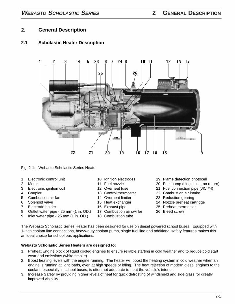
1 Electronic control unit2 Motor3 Electronic ignition coil4 Coupler5 Combustion air fan6 Solenoid valve7 Electrode holder8 Outlet water pipe - 25 mm (1 in. OD.)9 Inlet water pipe - 25 mm (1 in. OD.)
The Webasto Scholastic Series Heater has been designed for use on diesel powered school buses. Equipped with1-inch coolant line connections, heavy-duty coolant pump, single fuel line and additional safety features makes thisan ideal choice for school bus applications.
Webasto Scholastic Series Heaters are designed to:
1. Preheat Engine block of liquid cooled engines to ensure reliable starting in cold weather and to reduce cold startwear and emissions (white smoke).
2. Boost heating levels with the engine running. The heater will boost the heating system in cold weather when anengine is running at light loads, even at high speeds or idling. The heat rejection of modern diesel engines to thecoolant, especially in school buses, is often not adequate to heat the vehicle’s interior.
3. Increase Safety by providing higher levels of heat for quick defrosting of windshield and side glass for greatlyimproved visibility.
2. General Description
2.1 Scholastic Heater Description
Fig. 2-1: Webasto Scholastic Series Heater
10 Ignition electrodes11 Fuel nozzle12 Overheat fuse13 Control thermostat14 Overheat limiter15 Heat exchanger16 Exhaust pipe17 Combustion air swirler18 Combustion tube
19 Flame detection photocell20 Fuel pump (single line, no return)21 Fuel connection pipe (JIC #4)22 Combustion air intake23 Reduction gearing24 Nozzle preheat cartridge25 Preheat thermostat26 Bleed screw
WEBASTO SCHOLASTIC SERIES 3 FUNCTIONAL DESCRIPTION
3-1
3. Functional Description
3.1 Operating your Webasto Scholastic Heater
Before switching the Webasto heater on, set vehicle-heating system to the “Heat” position and open any shut offvalves. Depending on the type of control installed in the instrument panel of the vehicle, the heater can be operatedby the following methods.
WARNINGDue to the risk of carbon monoxide poisoning and asphyxiation, the heater must never be operated in closed spacessuch as garages and workshops without adequate exhaust extraction.
WARNINGDue to the risk of fire or explosion, the heater must be switched off while refueling and at fueling stations.
WARNINGDue to the risk of explosion, the heater must never be operated in areas where explosive materials, fumes or dustsmay be present.
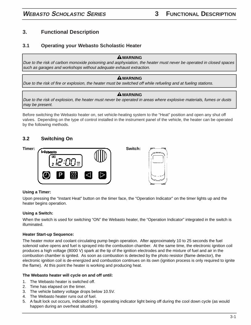
3.2 Switching On
Timer: Switch:
Using a Timer:
Upon pressing the “Instant Heat” button on the timer face, the “Operation Indicator” on the timer lights up and theheater begins operation.
Using a Switch:
When the switch is used for switching “ON” the Webasto heater, the “Operation Indicator” integrated in the switch isilluminated.
Heater Start-up Sequence:
The heater motor and coolant circulating pump begin operation. After approximately 10 to 25 seconds the fuelsolenoid valve opens and fuel is sprayed into the combustion chamber. At the same time, the electronic ignition coilproduces a high voltage (8000 V) spark at the tip of the ignition electrodes and the mixture of fuel and air in thecombustion chamber is ignited. As soon as combustion is detected by the photo resistor (flame detector), theelectronic ignition coil is de-energized and combustion continues on its own (ignition process is only required to ignitethe flame). At this point the heater is working and producing heat.
The Webasto heater will cycle on and off until:
1. The Webasto heater is switched off.2. Time has elapsed on the timer.3. The vehicle battery voltage drops below 10.5V.4. The Webasto heater runs out of fuel.5. A fault lock out occurs, indicated by the operating indicator light being off during the cool down cycle (as would
happen during an overheat situation).
3 FUNCTIONAL DESCRIPTION WEBASTO SCHOLASTIC SERIES
3-2
3.3 Switching Off
When heating is no longer required, switch the Webasto heater off. The fuel solenoid valve halts the fuel supply,combustion stops and the indicator light turns off. The Combustion air fan and the water pump remain on for another2-3 minutes (after run cycle) purging the combustion chamber of any fumes.
3.4 Engine Preheating
1. Set the timer 30 min. to 1 hr. before you want to start the engine. The heater will start up at the set time. (Seetimer operating instructions). Or switch the toggle switch or “Instant On” switch on your timer in the vehicle dashto “ON”. The heater will start up.
2. When the run time has elapsed on your timer or engine preheating is no longer required, switch the Webastoheater “OFF”. The heater will begin a brief after-run (cool down) cycle.
3.5 Boost Heating for Engine and Passenger Compartment
1. Switch the toggle switch (or the “Instant On” button of the timer) in the vehicle dash to “On”. The heater will startup if the coolant temperature is below 75 °C (167 °F). Above this temperature only the water pump will run.
2. When boost heating is no longer required, switch the Webasto heater “Off”. The heater will begin a brief after-run(cool-down) cycle.
3.6 Operation with 7-Day Digital Timer Model 1531
The digital timer with 3 time settings permits the Webasto heater to be switched on and off instantly, or automaticallyat 3 programmable starting times.
The operating time of the heater can be pre-selected. It is possible to program 3 different heating programsaccording to your individual needs.
Only one preset starting time can be activated at any one time. When the ignition is switched on, the current time ofthe day and the day of the week are displayed.
When the heater is in operation, the display and the buttons of the timer are illuminated.
Programmed Heater Operation
Three memory locations numbered 1 to 3 are available. Each memory location can be assigned a given timetogether with the day of the week.
Pre-selected Starting Times
The pre-selected starting time is the time at which the heater will be switched on automatically.
We recommend that memory locations 1 and 2 be used for presetting starting times within 24 hours of setting thetimer.
Memory location 3 can be used for a starting time within the next 7 days of setting the timer.
NOTE:If the heater is switched on while the engine is at operating temperatures above 68 °C (155 °F) only the operationindicator and the coolant circulation pump will be activated. The engine coolant temperature must fall below 68 °C(155 °F) at the heater before the heater will begin heating operation.
NOTE:Switching the Webasto heater on during the cool-down or “after-run” period is allowed. The heater will revert tonormal operational mode.
WEBASTO SCHOLASTIC SERIES 3 FUNCTIONAL DESCRIPTION
3-3
Operating Time
The period of time during which the heater is in operation is referred to as operating time. The heater remains inoperation for as long as the operating time has been preset.
Heater operation can be pre-selected for any time from as little as 1 minute to a maximum of 120 minutes (factorypreset is 60 minutes).
Remaining Operating Time
The remaining operating time refers to the period of time the heater still continues to remain in operation. It can onlybe changed while heater is in operation.
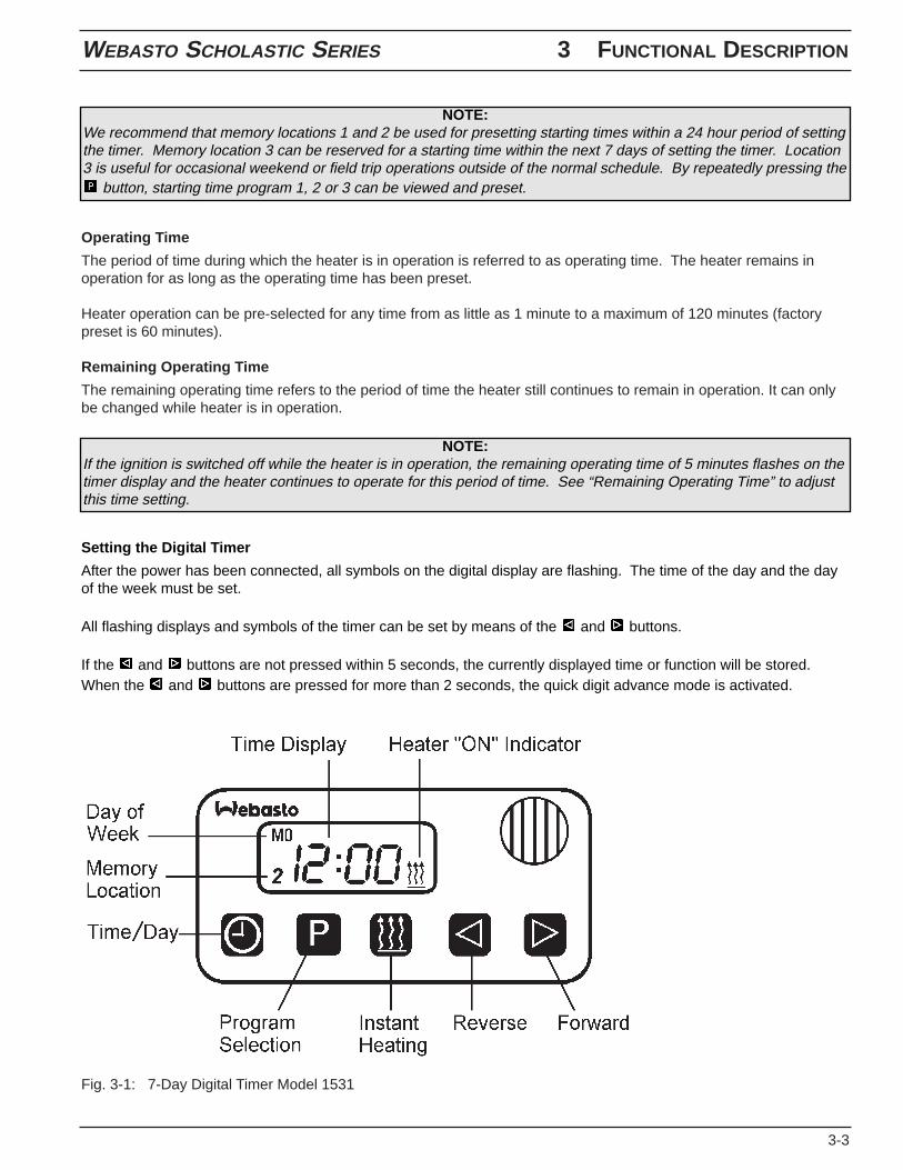
Fig. 3-1: 7-Day Digital Timer Model 1531
Setting the Digital Timer
After the power has been connected, all symbols on the digital display are flashing. The time of the day and the dayof the week must be set.
All flashing displays and symbols of the timer can be set by means of the and buttons.
If the and buttons are not pressed within 5 seconds, the currently displayed time or function will be stored.When the and buttons are pressed for more than 2 seconds, the quick digit advance mode is activated.
NOTE:If the ignition is switched off while the heater is in operation, the remaining operating time of 5 minutes flashes on thetimer display and the heater continues to operate for this period of time. See “Remaining Operating Time” to adjustthis time setting.
NOTE:We recommend that memory locations 1 and 2 be used for presetting starting times within a 24 hour period of settingthe timer. Memory location 3 can be reserved for a starting time within the next 7 days of setting the timer. Location3 is useful for occasional weekend or field trip operations outside of the normal schedule. By repeatedly pressing the
button, starting time program 1, 2 or 3 can be viewed and preset.
3 FUNCTIONAL DESCRIPTION WEBASTO SCHOLASTIC SERIES
3-4
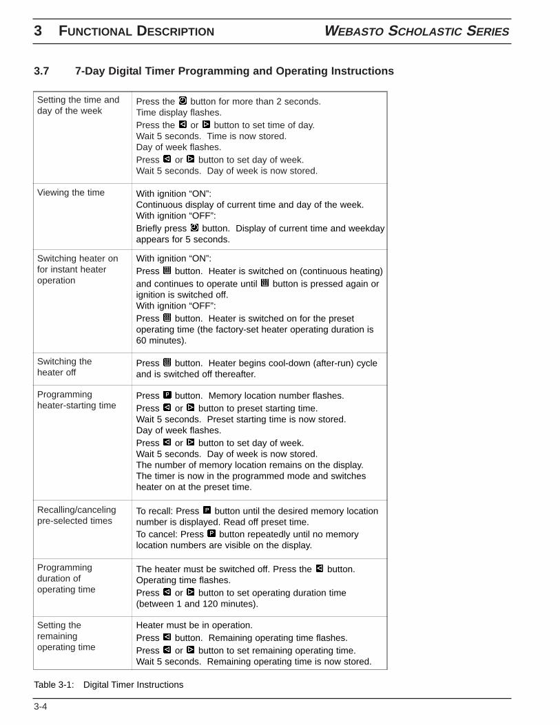
3.7 7-Day Digital Timer Programming and Operating Instructions
Setting the time andday of the week
Viewing the time
Switching heater onfor instant heateroperation
Switching theheater off
Programmingheater-starting time
Recalling/cancelingpre-selected times
Programmingduration ofoperating time
Setting theremainingoperating time
Press the button for more than 2 seconds.Time display flashes.Press the or button to set time of day.Wait 5 seconds. Time is now stored.Day of week flashes.Press or button to set day of week.Wait 5 seconds. Day of week is now stored.
With ignition “ON”:Continuous display of current time and day of the week.With ignition “OFF”:Briefly press button. Display of current time and weekdayappears for 5 seconds.
With ignition “ON”:Press button. Heater is switched on (continuous heating)and continues to operate until button is pressed again orignition is switched off.With ignition “OFF”:Press button. Heater is switched on for the presetoperating time (the factory-set heater operating duration is60 minutes).
Press button. Heater begins cool-down (after-run) cycleand is switched off thereafter.
Press button. Memory location number flashes.Press or button to preset starting time.Wait 5 seconds. Preset starting time is now stored.Day of week flashes.Press or button to set day of week.Wait 5 seconds. Day of week is now stored.The number of memory location remains on the display.The timer is now in the programmed mode and switchesheater on at the preset time.
To recall: Press button until the desired memory locationnumber is displayed. Read off preset time.To cancel: Press button repeatedly until no memorylocation numbers are visible on the display.
The heater must be switched off. Press the button.Operating time flashes.Press or button to set operating duration time(between 1 and 120 minutes).
Heater must be in operation.Press button. Remaining operating time flashes.Press or button to set remaining operating time.Wait 5 seconds. Remaining operating time is now stored.
Table 3-1: Digital Timer Instructions
WEBASTO SCHOLASTIC SERIES 4 TECHNICAL DATA
4-1
4. Technical Data
4.1 Scholastic Series Heater Data
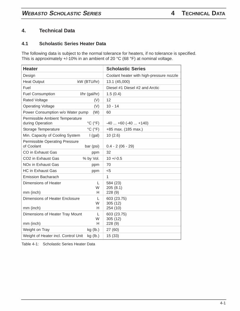
The following data is subject to the normal tolerance for heaters, if no tolerance is specified.This is approximately +/-10% in an ambient of 20 °C (68 °F) at nominal voltage.
Heater Scholastic SeriesDesign Coolant heater with high-pressure nozzle
Heat Output kW (BTU/hr) 13.1 (45,000)
Fuel Diesel #1 Diesel #2 and Arctic
Fuel Consumption l/hr (gal/hr) 1.5 (0.4)
Rated Voltage (V) 12
Operating Voltage (V) 10 - 14
Power Consumption w/o Water pump (W) 60
Permissible Ambient Temperatureduring Operation °C (°F) -40 ... +60 (-40 ... +140)
Storage Temperature °C (°F) +85 max. (185 max.)
Min. Capacity of Cooling System l (gal) 10 (2.6)
Permissible Operating Pressureof Coolant bar (psi) 0.4 - 2 (06 - 29)
CO in Exhaust Gas ppm 32
CO2 in Exhaust Gas % by Vol. 10 +/-0.5
NOx in Exhaust Gas ppm 70
HC in Exhaust Gas ppm <5
Emission Bacharach 1
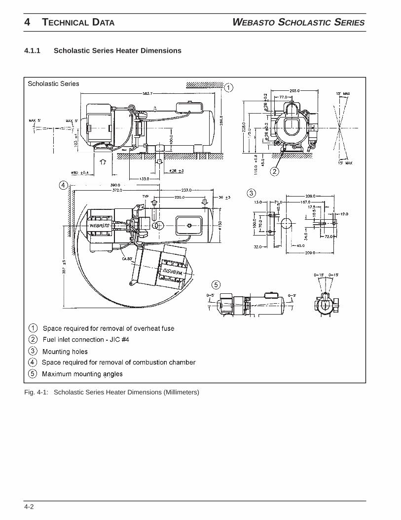
Dimensions of Heater L 584 (23)W 205 (8.1)
mm (inch) H 228 (9)
Dimensions of Heater Enclosure L 603 (23.75)W 305 (12)
mm (inch) H 254 (10)
Dimensions of Heater Tray Mount L 603 (23.75)W 305 (12)
mm (inch) H 228 (9)
Weight on Tray kg (lb.) 27 (60)
Weight of Heater incl. Control Unit kg (lb.) 15 (33)
Table 4-1: Scholastic Series Heater Data
4 TECHNICAL DATA WEBASTO SCHOLASTIC SERIES
4-2
4.1.1 Scholastic Series Heater Dimensions
Fig. 4-1: Scholastic Series Heater Dimensions (Millimeters)
WEBASTO SCHOLASTIC SERIES 4 TECHNICAL DATA
4-3
4.2 Coolant Circulation Pump Data
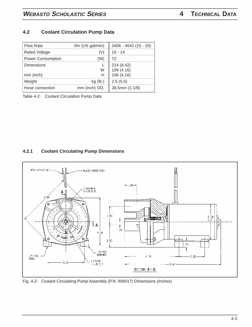
Flow Rate l/hr (US gal/min) 3406 - 4542 (15 - 20)
Rated Voltage (V) 10 - 14
Power Consumption (W) 72
Dimensions L 214 (8.42)W 106 (4.16)
mm (inch) H 106 (4.16)
Weight kg (lb.) 2.5 (5.5)
Hose connection mm (inch) OD. 28.5mm (1-1/8)
Table 4-2: Coolant Circulation Pump Data
4.2.1 Coolant Circulating Pump Dimensions
Fig. 4-2: Coolant Circulating Pump Assembly (P.N. 906017) Dimensions (Inches)
4 TECHNICAL DATA WEBASTO SCHOLASTIC SERIES
4-4
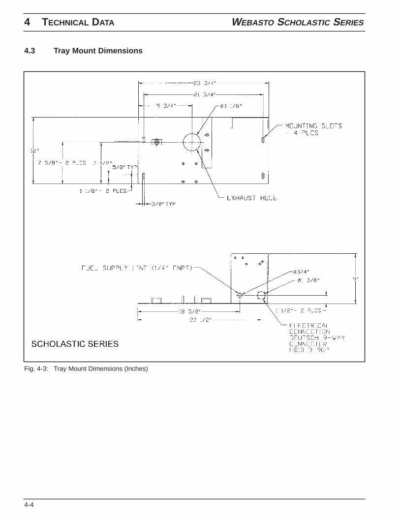
4.3 Tray Mount Dimensions
Fig. 4-3: Tray Mount Dimensions (Inches)
WEBASTO SCHOLASTIC SERIES 5 INSTALLATION
5-1
5. Installation
5.1 General Information
Webasto will take you step by step through the installation process to ensure successful operation for years to come.The installation must be performed in accordance with the installation instructions provided in this manual.
NOTE:This manual does not cover all possible installations. This manual is a general guideline only. For specialapplications or installations differing from what is described in this manual, contact Webasto Thermosystems directlyat 1-800-555-4518 for further information.
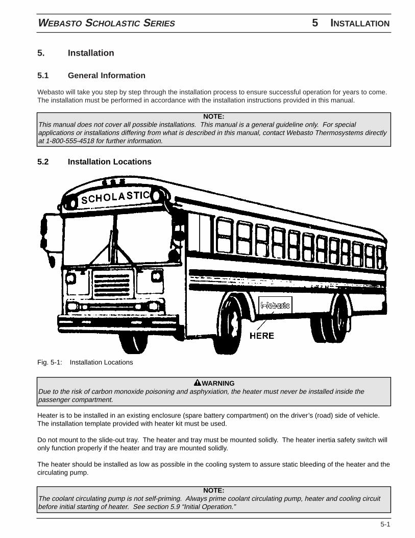
5.2 Installation Locations
Fig. 5-1: Installation Locations
WARNINGDue to the risk of carbon monoxide poisoning and asphyxiation, the heater must never be installed inside thepassenger compartment.
Heater is to be installed in an existing enclosure (spare battery compartment) on the driver’s (road) side of vehicle.The installation template provided with heater kit must be used.
Do not mount to the slide-out tray. The heater and tray must be mounted solidly. The heater inertia safety switch willonly function properly if the heater and tray are mounted solidly.
The heater should be installed as low as possible in the cooling system to assure static bleeding of the heater and thecirculating pump.
NOTE:The coolant circulating pump is not self-priming. Always prime coolant circulating pump, heater and cooling circuitbefore initial starting of heater. See section 5.9 “Initial Operation.”
5 INSTALLATION WEBASTO SCHOLASTIC SERIES
5-2
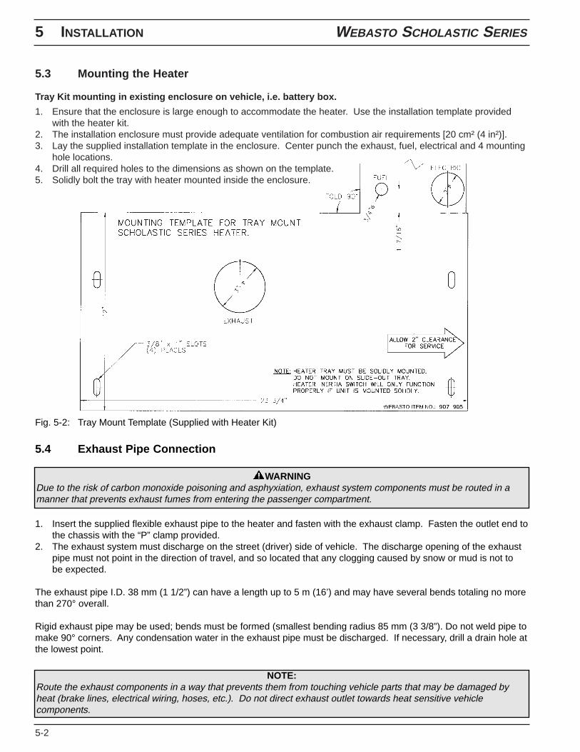
5.3 Mounting the Heater
Tray Kit mounting in existing enclosure on vehicle, i.e. battery box.
1. Ensure that the enclosure is large enough to accommodate the heater. Use the installation template providedwith the heater kit.
2. The installation enclosure must provide adequate ventilation for combustion air requirements [20 cm² (4 in²)].3. Lay the supplied installation template in the enclosure. Center punch the exhaust, fuel, electrical and 4 mounting
hole locations.4. Drill all required holes to the dimensions as shown on the template.5. Solidly bolt the tray with heater mounted inside the enclosure.
Fig. 5-2: Tray Mount Template (Supplied with Heater Kit)
5.4 Exhaust Pipe Connection
WARNINGDue to the risk of carbon monoxide poisoning and asphyxiation, exhaust system components must be routed in amanner that prevents exhaust fumes from entering the passenger compartment.
1. Insert the supplied flexible exhaust pipe to the heater and fasten with the exhaust clamp. Fasten the outlet end tothe chassis with the “P” clamp provided.
2. The exhaust system must discharge on the street (driver) side of vehicle. The discharge opening of the exhaustpipe must not point in the direction of travel, and so located that any clogging caused by snow or mud is not tobe expected.
The exhaust pipe I.D. 38 mm (1 1/2”) can have a length up to 5 m (16’) and may have several bends totaling no morethan 270° overall.
Rigid exhaust pipe may be used; bends must be formed (smallest bending radius 85 mm (3 3/8”). Do not weld pipe tomake 90° corners. Any condensation water in the exhaust pipe must be discharged. If necessary, drill a drain hole atthe lowest point.
NOTE:Route the exhaust components in a way that prevents them from touching vehicle parts that may be damaged byheat (brake lines, electrical wiring, hoses, etc.). Do not direct exhaust outlet towards heat sensitive vehiclecomponents.
WEBASTO SCHOLASTIC SERIES 5 INSTALLATION
5-3
WARNINGDue to the risk of carbon monoxide poisoning and asphyxiation, never draw combustion air from inside the vehiclespassenger compartment.
5.5 Combustion Air Supply
1. Never draw combustion air from inside the vehicle, or from areas where fumes or gases can accumulate.2. The installation housing must provide adequate ventilation for combustion air requirements [20 cm² (4 in²)].
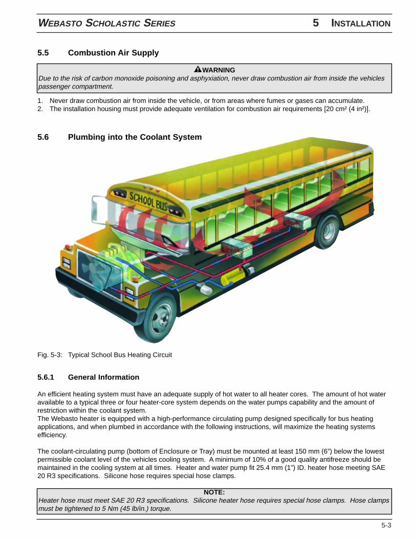
Fig. 5-3: Typical School Bus Heating Circuit
5.6.1 General Information
An efficient heating system must have an adequate supply of hot water to all heater cores. The amount of hot wateravailable to a typical three or four heater-core system depends on the water pumps capability and the amount ofrestriction within the coolant system.The Webasto heater is equipped with a high-performance circulating pump designed specifically for bus heatingapplications, and when plumbed in accordance with the following instructions, will maximize the heating systemsefficiency.
The coolant-circulating pump (bottom of Enclosure or Tray) must be mounted at least 150 mm (6”) below the lowestpermissible coolant level of the vehicles cooling system. A minimum of 10% of a good quality antifreeze should bemaintained in the cooling system at all times. Heater and water pump fit 25.4 mm (1”) ID. heater hose meeting SAE20 R3 specifications. Silicone hose requires special hose clamps.
NOTE:Heater hose must meet SAE 20 R3 specifications. Silicone heater hose requires special hose clamps. Hose clampsmust be tightened to 5 Nm (45 lb/in.) torque.
5.6 Plumbing into the Coolant System
5 INSTALLATION WEBASTO SCHOLASTIC SERIES
5-4
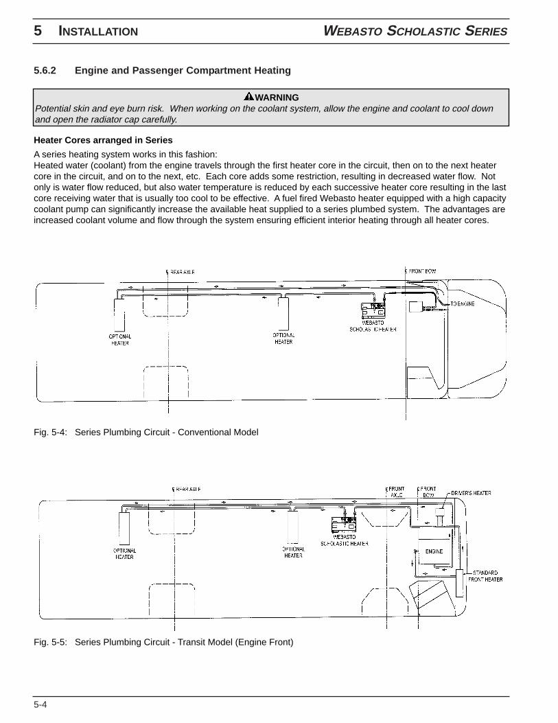
5.6.2 Engine and Passenger Compartment Heating
WARNINGPotential skin and eye burn risk. When working on the coolant system, allow the engine and coolant to cool downand open the radiator cap carefully.
Heater Cores arranged in Series
A series heating system works in this fashion:Heated water (coolant) from the engine travels through the first heater core in the circuit, then on to the next heatercore in the circuit, and on to the next, etc. Each core adds some restriction, resulting in decreased water flow. Notonly is water flow reduced, but also water temperature is reduced by each successive heater core resulting in the lastcore receiving water that is usually too cool to be effective. A fuel fired Webasto heater equipped with a high capacitycoolant pump can significantly increase the available heat supplied to a series plumbed system. The advantages areincreased coolant volume and flow through the system ensuring efficient interior heating through all heater cores.
Fig. 5-4: Series Plumbing Circuit - Conventional Model
Fig. 5-5: Series Plumbing Circuit - Transit Model (Engine Front)
WEBASTO SCHOLASTIC SERIES 5 INSTALLATION
5-5
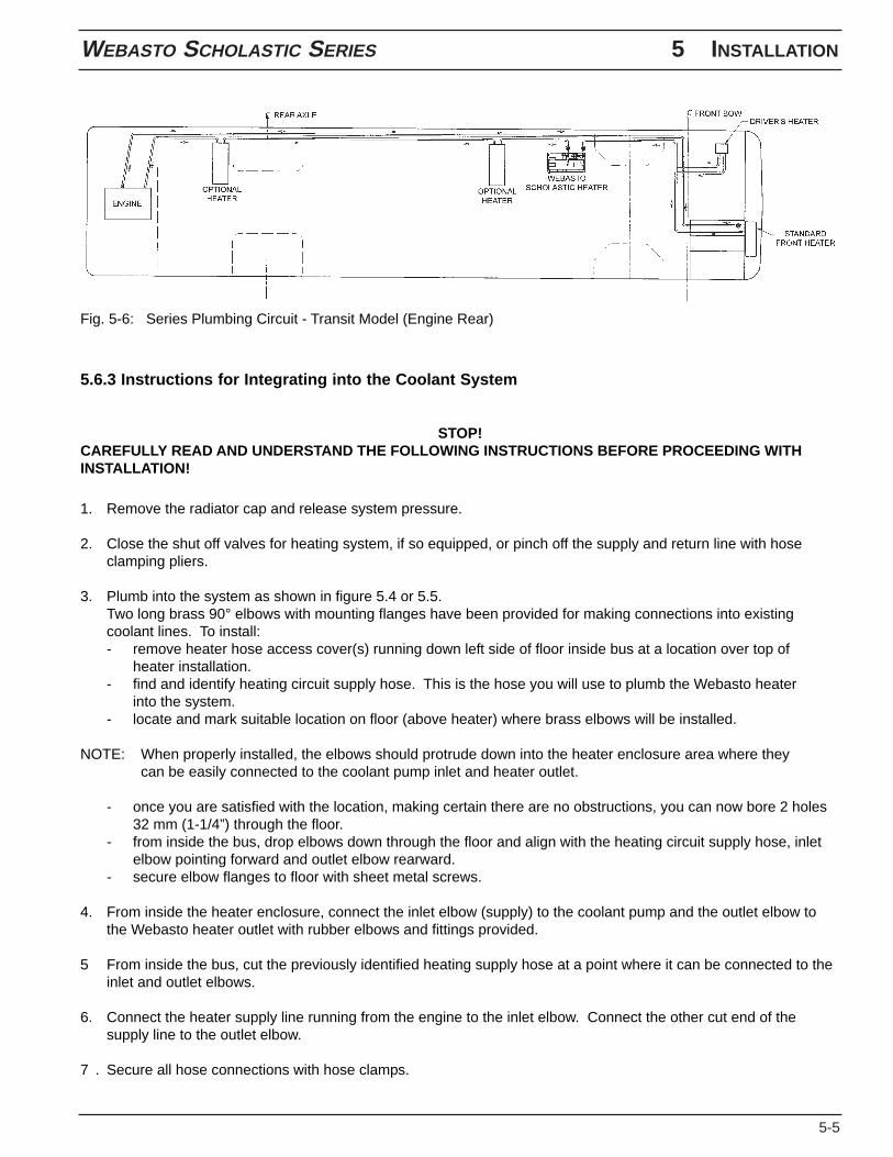
Fig. 5-6: Series Plumbing Circuit - Transit Model (Engine Rear)
5.6.3 Instructions for Integrating into the Coolant System
STOP!CAREFULLY READ AND UNDERSTAND THE FOLLOWING INSTRUCTIONS BEFORE PROCEEDING WITHINSTALLATION!
1. Remove the radiator cap and release system pressure.
2. Close the shut off valves for heating system, if so equipped, or pinch off the supply and return line with hoseclamping pliers.
3. Plumb into the system as shown in figure 5.4 or 5.5.Two long brass 90° elbows with mounting flanges have been provided for making connections into existingcoolant lines. To install:- remove heater hose access cover(s) running down left side of floor inside bus at a location over top of
heater installation.- find and identify heating circuit supply hose. This is the hose you will use to plumb the Webasto heater
into the system.- locate and mark suitable location on floor (above heater) where brass elbows will be installed.
NOTE: When properly installed, the elbows should protrude down into the heater enclosure area where theycan be easily connected to the coolant pump inlet and heater outlet.
- once you are satisfied with the location, making certain there are no obstructions, you can now bore 2 holes32 mm (1-1/4”) through the floor.
- from inside the bus, drop elbows down through the floor and align with the heating circuit supply hose, inletelbow pointing forward and outlet elbow rearward.
- secure elbow flanges to floor with sheet metal screws.
4. From inside the heater enclosure, connect the inlet elbow (supply) to the coolant pump and the outlet elbow tothe Webasto heater outlet with rubber elbows and fittings provided.
5 From inside the bus, cut the previously identified heating supply hose at a point where it can be connected to theinlet and outlet elbows.
6. Connect the heater supply line running from the engine to the inlet elbow. Connect the other cut end of thesupply line to the outlet elbow.
7 . Secure all hose connections with hose clamps.
5 INSTALLATION WEBASTO SCHOLASTIC SERIES
5-6
8 Remove hose clamping pliers and/ or open shut off valves.
9. Purge air from the Webasto heater by opening the bleeder valve screw (see page 2-1, figure 2-1, item 26).
10. Top off engine coolant as per engine manufacturer’s recommendations and re-install the radiator cap.
Do not install the previously removed heater hose access covers at this time. Hose connections will requireinspection and re-tightening of clamps once installation is completed and tested (see section 5.9 “Initial Operation”).
NOTE:Heater hose must meet SAE 20 R3 specifications. Silicone heater hose requires special hose clamps. Hose clampsmust be tightened to 5 Nm (45 lb/in.) torque.
WEBASTO SCHOLASTIC SERIES 5 INSTALLATION
5-7
5.7 Fuel System
5.7.1 General Description
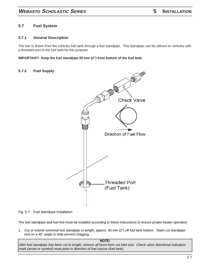
The fuel is drawn from the vehicles fuel tank through a fuel standpipe. This standpipe can be utilized on vehicles witha threaded port in the fuel tank for this purpose.
IMPORTANT! Keep the fuel standpipe 50 mm (2”) from bottom of the fuel tank.
5.7.2 Fuel Supply
Fig. 5-7: Fuel Standpipe Installation
The fuel standpipe and fuel line must be installed according to these instructions to ensure proper heater operation.
1. Cut or extend universal fuel standpipe to length, approx. 50 mm (2”) off fuel tank bottom. Slash cut standpipeend on a 45° angle to help prevent clogging.
NOTE:After fuel standpipe has been cut to length, remove all burrs from cut inlet end. Check valve directional indicationmark (arrow or symbol) must point in direction of fuel source (fuel tank).
5 INSTALLATION WEBASTO SCHOLASTIC SERIES
5-8
2. Install the universal fuel standpipe and 3/8” check valve. Check valve directional indication mark (arrow orsymbol) must point in direction of fuel source (fuel tank).- use 1/4” or 1/2” spare port on fuel tank and install fuel standpipe securely in fuel tank, use pipe thread sealant
on all pipe threads.
3. Route and secure fuel line from heater to fuel tank. Do not route fuel line over frame rails, always route throughor under the frame rail. Use grommets to protect fuel line whenever routed through holes.
4. Connect fuel line to fuel standpipe using 3 mm (1/8”) fuel hose meeting SAE 30RI specifications.
CAUTIONOn School Bus applications, fuel lines must not cross over top of the vehicle frame rails. Check local and Statecodes and regulations for exceptions.
CAUTIONFuel lines must be secured every 30 cm (12 inches) or less and kept clear of hot exhaust components and movingparts (driveshaft, wheels, etc.).
NOTE:Use supplied hose clamps to secure fuel line connections.
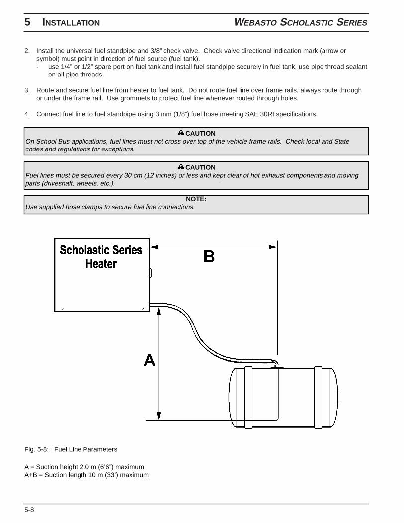
Fig. 5-8: Fuel Line Parameters
A = Suction height 2.0 m (6’6”) maximumA+B = Suction length 10 m (33’) maximum
WEBASTO SCHOLASTIC SERIES 5 INSTALLATION
5-9
5.7.3 Fuel Filter
Your heater is equipped with a spin-on fuel filter. Fuel filters require changing at least annually and in cases of dirtyfuel more often.
The fuel filter assembly should be mounted securely between the vehicle frame rails close to the fuel tank. Afterinstallation, before the heater is fired for the first time, the fuel filter MUST be filled with CLEAN diesel fuel. Whenreplacing the fuel filter, this procedure must be repeated to ensure proper firing and operation.
CAUTIONCheck local and State codes and regulations for fuel filter mounting locations.
CAUTIONTo prevent fuel nozzle failure, always use CLEAN fuel from a known CLEAN source for priming fuel systems andfilters.
NOTEThe Webasto Scholastic Series heater is equipped with an internal self-priming fuel pump.
5 INSTALLATION WEBASTO SCHOLASTIC SERIES
5-10
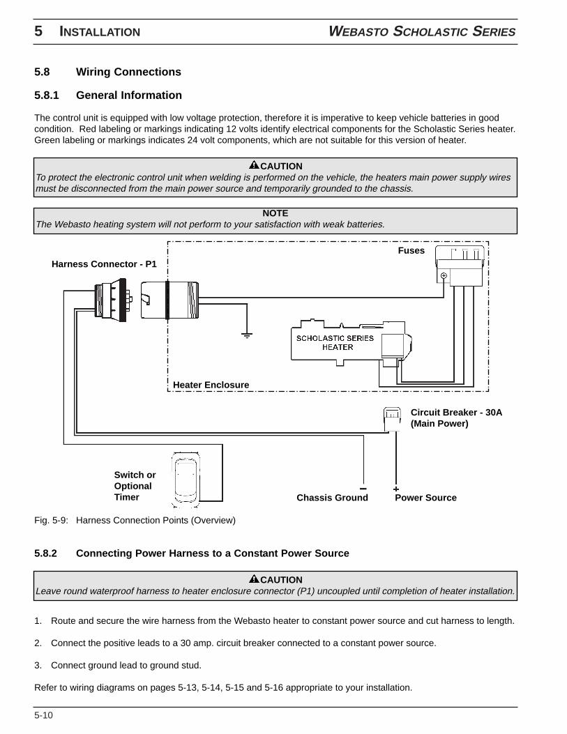
5.8 Wiring Connections
5.8.1 General Information
The control unit is equipped with low voltage protection, therefore it is imperative to keep vehicle batteries in goodcondition. Red labeling or markings indicating 12 volts identify electrical components for the Scholastic Series heater.Green labeling or markings indicates 24 volt components, which are not suitable for this version of heater.
CAUTIONTo protect the electronic control unit when welding is performed on the vehicle, the heaters main power supply wiresmust be disconnected from the main power source and temporarily grounded to the chassis.
NOTEThe Webasto heating system will not perform to your satisfaction with weak batteries.
Fig. 5-9: Harness Connection Points (Overview)
5.8.2 Connecting Power Harness to a Constant Power Source
1. Route and secure the wire harness from the Webasto heater to constant power source and cut harness to length.
2. Connect the positive leads to a 30 amp. circuit breaker connected to a constant power source.
3. Connect ground lead to ground stud.
Refer to wiring diagrams on pages 5-13, 5-14, 5-15 and 5-16 appropriate to your installation.
CAUTIONLeave round waterproof harness to heater enclosure connector (P1) uncoupled until completion of heater installation.
Chassis Ground Power Source
Circuit Breaker - 30A(Main Power)
FusesHarness Connector - P1
Switch orOptionalTimer
Heater Enclosure
5.8.4 Timer and Switch Installation
1. Locate appropriate switch knock-out (blank) on instrument panel for heater On/Off switch or select a suitablelocation in the vehicle dash for the (optional) timer.
2. Remove switch knock-out and replace with appropriate switch. Timer is supplied with a removablestick-on drilling template.
3. Route and secure switch harness from the heater to the vehicle dashboard. If possible use existing hole in firewall/ panel or drill in suitable location. Protect the harness with a grommet whenever passing through firewall/ panel holes.
4. Connect the terminals to the switch or timer. See pages 5-13, 5-14, 5-15 and 5-16 for complete wiring details.
CAUTIONMake sure there is enough space behind the dash for the switch or timer and wire connections before cutting anyholes.
CAUTIONTo prevent damage to electrical and mechanical components, check for clearance before drilling into panels andframe members.
WEBASTO SCHOLASTIC SERIES 5 INSTALLATION
5-11
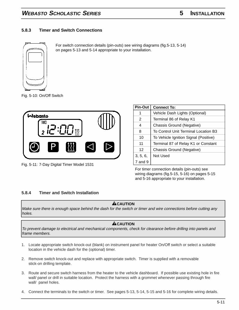
5.8.3 Timer and Switch Connections
Fig. 5-10: On/Off Switch
Fig. 5-11: 7-Day Digital Timer Model 1531
For switch connection details (pin-outs) see wiring diagrams (fig.5-13, 5-14)on pages 5-13 and 5-14 appropriate to your installation.
1 Vehicle Dash Lights (Optional)
2 Terminal 86 of Relay K1
4 Chassis Ground (Negative)
8 To Control Unit Terminal Location B3
10 To Vehicle Ignition Signal (Positive)
11 Terminal 87 of Relay K1 or Constant
12 Chassis Ground (Negative)
3, 5, 6, Not Used
7 and 9
Pin-Out Connect To:
For timer connection details (pin-outs) seewiring diagrams (fig.5-15, 5-16) on pages 5-15and 5-16 appropriate to your installation.
5 INSTALLATION WEBASTO SCHOLASTIC SERIES
5-12
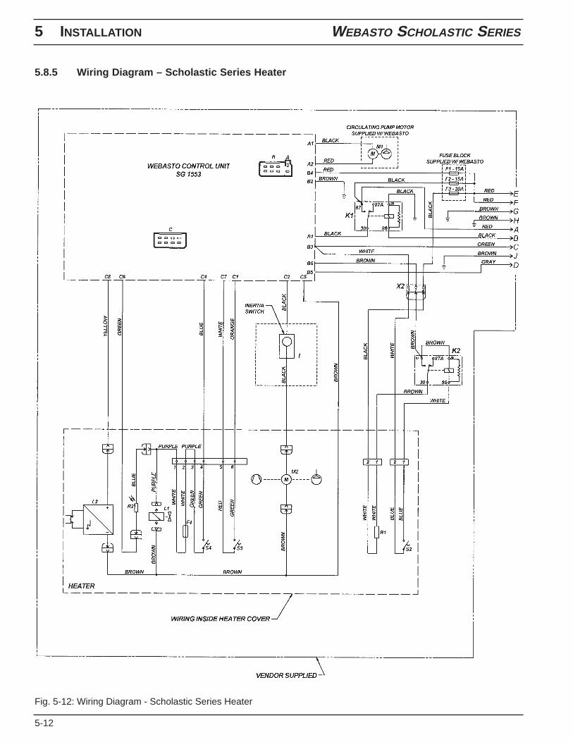
5.8.5 Wiring Diagram – Scholastic Series Heater
Fig. 5-12: Wiring Diagram - Scholastic Series Heater
WEBASTO SCHOLASTIC SERIES 5 INSTALLATION
5-13
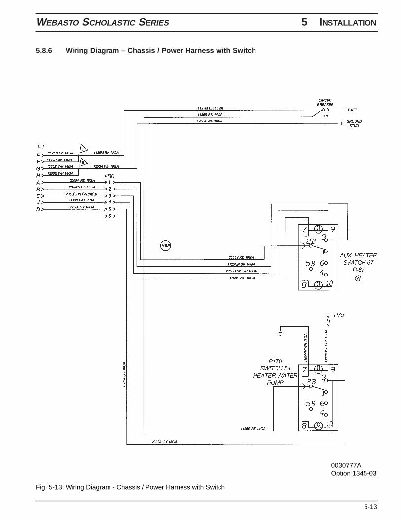
5.8.6 Wiring Diagram – Chassis / Power Harness with Switch
Fig. 5-13: Wiring Diagram - Chassis / Power Harness with Switch
0030777AOption 1345-03
5 INSTALLATION WEBASTO SCHOLASTIC SERIES
5-14
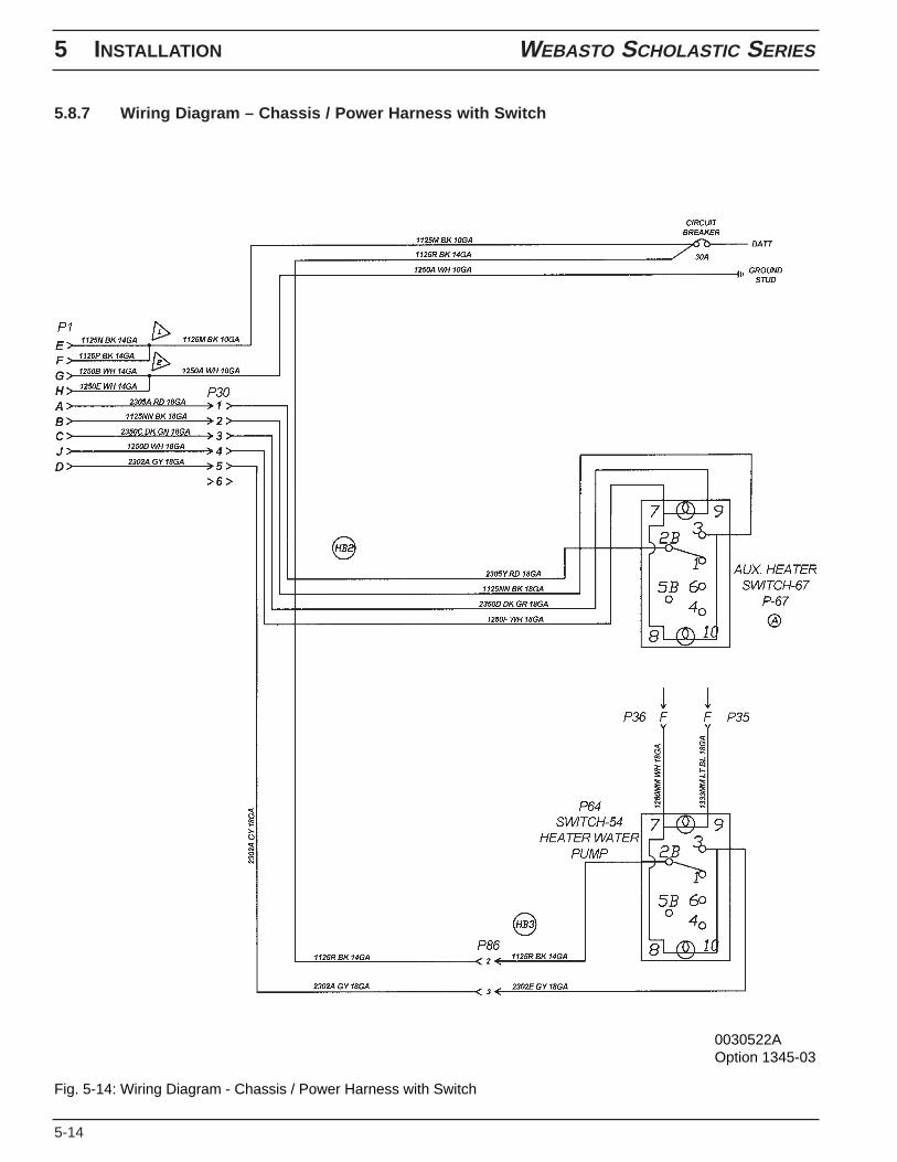
5.8.7 Wiring Diagram – Chassis / Power Harness with Switch
Fig. 5-14: Wiring Diagram - Chassis / Power Harness with Switch
0030522AOption 1345-03
WEBASTO SCHOLASTIC SERIES 5 INSTALLATION
5-15
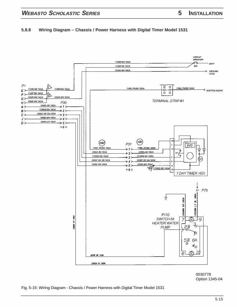
5.8.8 Wiring Diagram – Chassis / Power Harness with Digital Timer Model 1531
Fig. 5-15: Wiring Diagram - Chassis / Power Harness with Digital Timer Model 1531
0030778Option 1345-04
5 INSTALLATION WEBASTO SCHOLASTIC SERIES
5-16
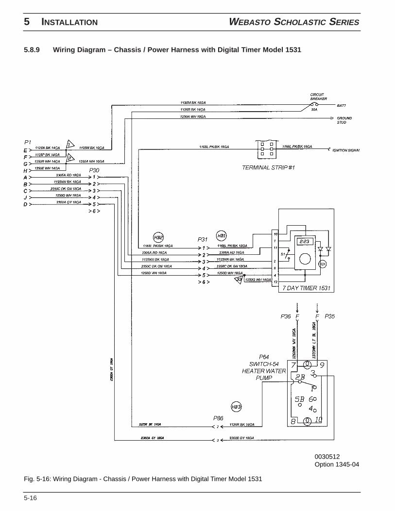
5.8.9 Wiring Diagram – Chassis / Power Harness with Digital Timer Model 1531
Fig. 5-16: Wiring Diagram - Chassis / Power Harness with Digital Timer Model 1531
0030512Option 1345-04
WEBASTO SCHOLASTIC SERIES 5 INSTALLATION
5-17
5.9 Initial Operation
1. Check your installation for:- loose nuts and bolts.- exhaust pipe routing and clamp tightness.- loose hose clamps.- routing and securing of wiring and heater hoses.- kinked or pinched hoses.- battery connection and polarity.- disconnect control thermostat on Webasto heat exchanger (red and green wire, see page 2-1, figure 2-1,
position 13).
2. Top off or refill cooling system with coolant as per engine manufacturer’s recommendations.
3. Connect power/ switch extension harness to waterproof plug.
4. Open shut-off valves and driver’s heater valve.
5. Set heater controls to maximum heat position and turn off Air Conditioning if applicable.
6. Switch “On” Webasto heater and check:- green indicator light on.- circulating pump in operation.
7. Start the vehicle engine and run it at a fast idle for 10 minutes to purge air from the Webasto coolant heater andall of the heat exchangers. While the engine is running check:- hose connections for leaks.- coolant level in the expansion tank and add coolant as needed.- use bleeder valve screw on top of Webasto heat exchanger to purge out any trapped air (see page 2-1, figure
2-1, item 26).
8. Shut off the engine.
9. Plug in control thermostat, the blower motor starts and the fuel pump primes the fuel lines. After 10 to 25 sec. thefuel solenoid opens and the electronic ignition coil ignites the air fuel mixture.
NOTEInstallations with long fuel lines may require a second start attempt to prime the fuel system. Cycle switch or timer offand on to reset control unit. Coolant temperature must be below 68 °C (155 °F) at heater before heater will beginheating operation.
10. Allow heater to run until coolant is hot and heater cycles off. During this period, monitor system for any coolant orfuel leaks.
NOTEThe engine temperature gauge may read a lower temperature depending on the location of the temperature sensoron the engine.
11. Temperature differential between water inlet and outlet should not exceed 10 °C (18 °F) during heating operation.
12. Switch “Off” Webasto heater.
13. Re-tighten hose clamps to 5 Nm. (45 lb/in.) and inspect installation for leaks.
14. Install any panels and access covers removed during installation.
5 INSTALLATION WEBASTO SCHOLASTIC SERIES
5-18
15. Complete the warranty card and send to Webasto Thermosystems (There is an area on the last page of thismanual for recording information that is useful when calling for technical support).
16. Install the enclosure cover if equipped. Installation is now complete.
NOTENecessary information to complete the warranty card can be found on the name plate on top of the heater burnerhead. The completion of the warranty card will ensure full warranty coverage. Please mail completed warranty cardwithin 30 days of purchase to register your heater.
WEBASTO SCHOLASTIC SERIES 6 HEATER MAINTENANCE
6-1
6. Heater Maintenance
6.1 Annual Maintenance
The Webasto heater requires a minimum of maintenance to operate.To keep your Webasto heater in good working order, the following maintenance procedures should be performedannually before each heating season:
Enclosure Area
- clean the heater and enclosure area of any accumulated debris or dust with compressed air.- inspect all components for wear and damage.
Electrical System
- check all wiring harnesses for damage and corrosion, repair or replace if required.- check the condition of the batteries and the connections.- load test the batteries and replace if necessary.
NOTEFor major repairs and service parts, return to your authorized Webasto Thermosystems Specialist.
Exhaust System
- check the exhaust system carefully for restrictions or corroded areas. Replace worn or damaged exhaustcomponents as necessary.
Fuel System
- replace the fuel filter (prime) and inspect the fuel line for wear and damage. Repair or replace if necessary.
Burner System
- swing open the burner head, clean the flame detection (photo eye), pull out the combustion chamber, inspectand clean the inside area of the heat exchanger. Replace the fuel nozzle if necessary (annually). Reinstallthe combustion chamber and close up the burner head.
Operational Check
- Run your heating system for at least 15 minutes.- Check all water and fuel connections for leakage. Check tightness of all hose clamps if necessary.
NOTEThe heater will not function properly or to your satisfaction with weak batteries.
NOTEOperate your Webasto heater at least once a month for 10 minutes.
CAUTIONAnnual maintenance requires basic product knowledge and maintenance procedures and should only be performedby Webasto trained and certified, skilled personnel. Ask your Webasto representative about training clinics.
WEBASTO SCHOLASTIC SERIES 7 BASIC TROUBLESHOOTING
7-1
7. Basic Troubleshooting
7.1 General Information
This section describes troubleshooting procedures for the Scholastic Series coolant heater. Troubleshooting isnormally limited to the isolation of defective components.
CAUTIONTroubleshooting requires profound knowledge about structure and theory of operation of the heater. Troubleshootingmay only be performed by Webasto trained and certified, skilled personnel.
Before troubleshooting, check for and eliminate the following causes for problems:
- fuel supply (plugged fuel filter or pinched fuel line)
- corrosion of battery terminals
- corrosion of electrical wiring, connections and fuses
- loose contacts or wrong crimping on connectors
- shut-down initiated by temperature limiter (automatic reset)
- shut-down initiated by overheat fuse (replace fuse)
- shut-down initiated by inertia switch (manual reset)
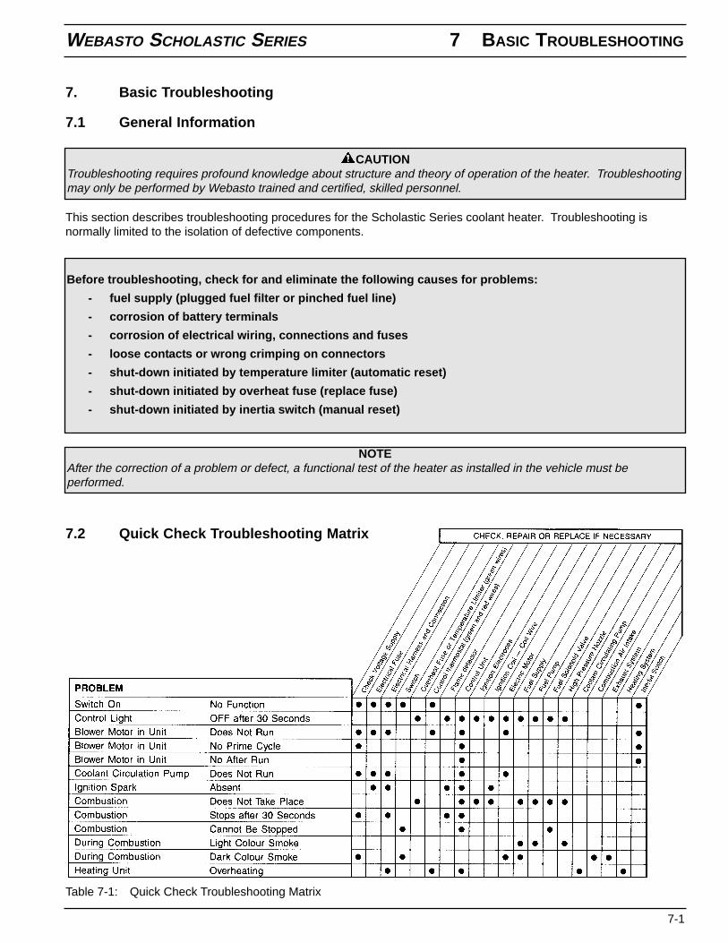
Table 7-1: Quick Check Troubleshooting Matrix
7.2 Quick Check Troubleshooting Matrix
NOTEAfter the correction of a problem or defect, a functional test of the heater as installed in the vehicle must beperformed.
7 BASIC TROUBLESHOOTING WEBASTO SCHOLASTIC SERIES
7-2
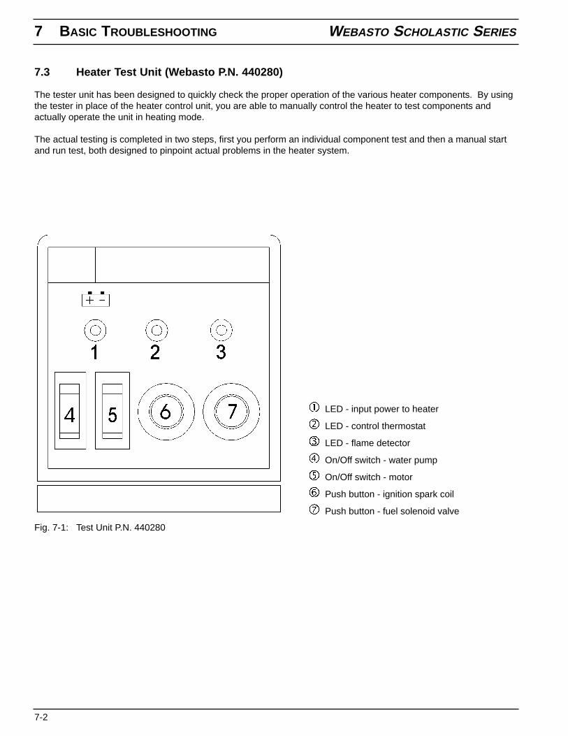
7.3 Heater Test Unit (Webasto P.N. 440280)
The tester unit has been designed to quickly check the proper operation of the various heater components. By usingthe tester in place of the heater control unit, you are able to manually control the heater to test components andactually operate the unit in heating mode.
The actual testing is completed in two steps, first you perform an individual component test and then a manual startand run test, both designed to pinpoint actual problems in the heater system.
Fig. 7-1: Test Unit P.N. 440280
LED - input power to heater
LED - control thermostat
LED - flame detector
On/Off switch - water pump
On/Off switch - motor
Push button - ignition spark coil
Push button - fuel solenoid valve
WEBASTO SCHOLASTIC SERIES 7 BASIC TROUBLESHOOTING
7-3
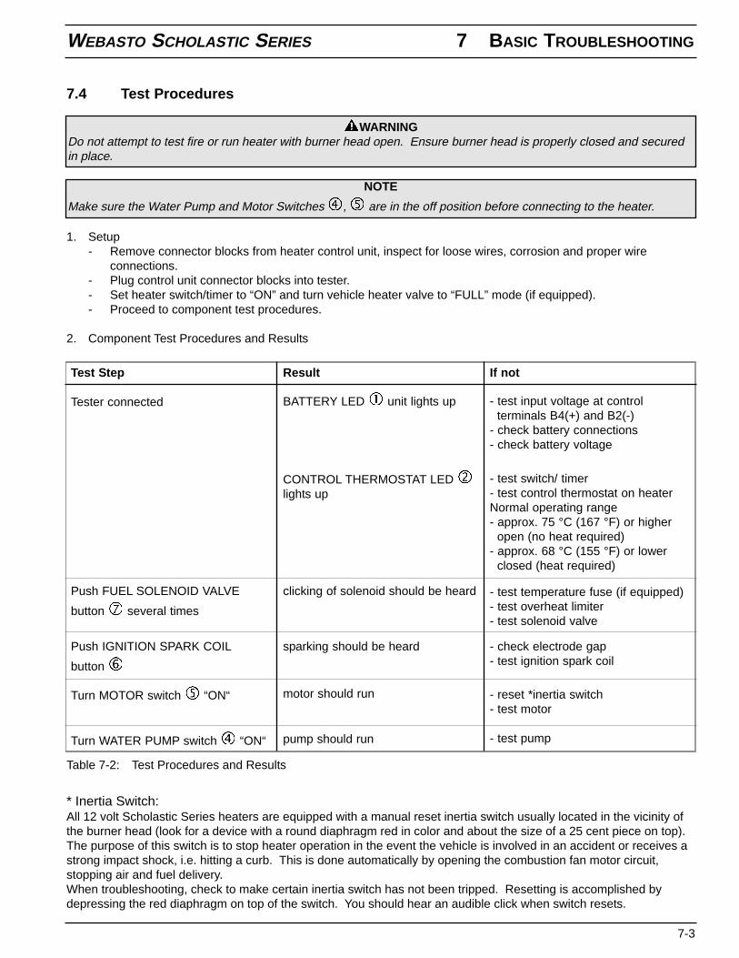
7.4 Test Procedures
1. Setup- Remove connector blocks from heater control unit, inspect for loose wires, corrosion and proper wire
connections.- Plug control unit connector blocks into tester.- Set heater switch/timer to “ON” and turn vehicle heater valve to “FULL” mode (if equipped).- Proceed to component test procedures.
2. Component Test Procedures and Results
WARNINGDo not attempt to test fire or run heater with burner head open. Ensure burner head is properly closed and securedin place.
NOTE
Make sure the Water Pump and Motor Switches , are in the off position before connecting to the heater.
If not
- test input voltage at controlterminals B4(+) and B2(-)
- check battery connections- check battery voltage
- test temperature fuse (if equipped)- test overheat limiter- test solenoid valve
- check electrode gap- test ignition spark coil
ResultTest Step
BATTERY LED unit lights up
CONTROL THERMOSTAT LEDlights up
Tester connected
Push FUEL SOLENOID VALVE
button several times
clicking of solenoid should be heard
sparking should be heardPush IGNITION SPARK COIL
button
Turn MOTOR switch “ON“ motor should run - reset *inertia switch- test motor
Turn WATER PUMP switch “ON“ pump should run - test pump
Table 7-2: Test Procedures and Results
* Inertia Switch:All 12 volt Scholastic Series heaters are equipped with a manual reset inertia switch usually located in the vicinity ofthe burner head (look for a device with a round diaphragm red in color and about the size of a 25 cent piece on top).The purpose of this switch is to stop heater operation in the event the vehicle is involved in an accident or receives astrong impact shock, i.e. hitting a curb. This is done automatically by opening the combustion fan motor circuit,stopping air and fuel delivery.When troubleshooting, check to make certain inertia switch has not been tripped. Resetting is accomplished bydepressing the red diaphragm on top of the switch. You should hear an audible click when switch resets.
- test switch/ timer- test control thermostat on heaterNormal operating range- approx. 75 °C (167 °F) or higher
open (no heat required)- approx. 68 °C (155 °F) or lower
closed (heat required)
7 BASIC TROUBLESHOOTING WEBASTO SCHOLASTIC SERIES
7-4
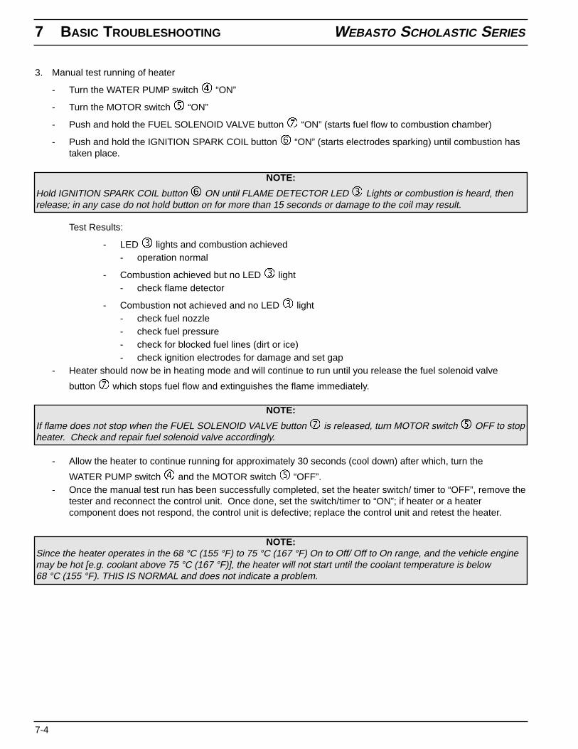
3. Manual test running of heater
- Turn the WATER PUMP switch “ON”
- Turn the MOTOR switch “ON”
- Push and hold the FUEL SOLENOID VALVE button “ON” (starts fuel flow to combustion chamber)
- Push and hold the IGNITION SPARK COIL button “ON” (starts electrodes sparking) until combustion hastaken place.
Test Results:
- LED lights and combustion achieved- operation normal
- Combustion achieved but no LED light- check flame detector
- Combustion not achieved and no LED light- check fuel nozzle- check fuel pressure- check for blocked fuel lines (dirt or ice)- check ignition electrodes for damage and set gap
- Heater should now be in heating mode and will continue to run until you release the fuel solenoid valve
button which stops fuel flow and extinguishes the flame immediately.
NOTE:
Hold IGNITION SPARK COIL button ON until FLAME DETECTOR LED Lights or combustion is heard, thenrelease; in any case do not hold button on for more than 15 seconds or damage to the coil may result.
- Allow the heater to continue running for approximately 30 seconds (cool down) after which, turn the
WATER PUMP switch and the MOTOR switch “OFF”.- Once the manual test run has been successfully completed, set the heater switch/ timer to “OFF”, remove the
tester and reconnect the control unit. Once done, set the switch/timer to “ON”; if heater or a heatercomponent does not respond, the control unit is defective; replace the control unit and retest the heater.
NOTE:
If flame does not stop when the FUEL SOLENOID VALVE button is released, turn MOTOR switch OFF to stopheater. Check and repair fuel solenoid valve accordingly.
NOTE:Since the heater operates in the 68 °C (155 °F) to 75 °C (167 °F) On to Off/ Off to On range, and the vehicle enginemay be hot [e.g. coolant above 75 °C (167 °F)], the heater will not start until the coolant temperature is below68 °C (155 °F). THIS IS NORMAL and does not indicate a problem.
WEBASTO SCHOLASTIC SERIES 8 SPARE PARTS LIST
8-1
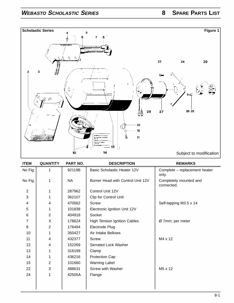
No Fig. 1 92119B Basic Scholastic Heater 12V Complete – replacement heateronly.
No Fig. 1 NA Burner Head with Control Unit 12V Completely mounted andconnected.
2 1 287962 Control Unit 12V
3 1 362107 Clip for Control Unit
4 4 470562 Screw Self-tapping M3.5 x 14
5 1 101838 Electronic Ignition Unit 12V
6 2 404918 Socket
7 X 178624 High Tension Ignition Cables Ø 7mm; per meter
8 2 176494 Electrode Plug
10 1 350427 Air Intake Bellows
11 4 432377 Screw M4 x 12
12 4 152269 Serrated Lock Washer
13 1 316199 Clamp
14 1 436216 Protection Cap
15 2 101660 Warning Label
22 3 488631 Screw with Washer M5 x 12
24 1 42505A Flange
ITEM QUANTITY PART NO. DESCRIPTION REMARKS
Figure 1Scholastic Series
Subject to modification
8 SPARE PARTS LIST WEBASTO SCHOLASTIC SERIES
8-2
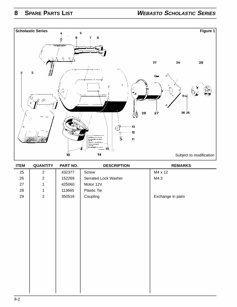
25 2 432377 Screw M4 x 12
26 2 152269 Serrated Lock Washer M4.3
27 1 425060 Motor 12V
28 1 113665 Plastic Tie
29 2 350516 Coupling Exchange in pairs
ITEM QUANTITY PART NO. DESCRIPTION REMARKS
Figure 1Scholastic Series
Subject to modification
WEBASTO SCHOLASTIC SERIES 8 SPARE PARTS LIST
8-3
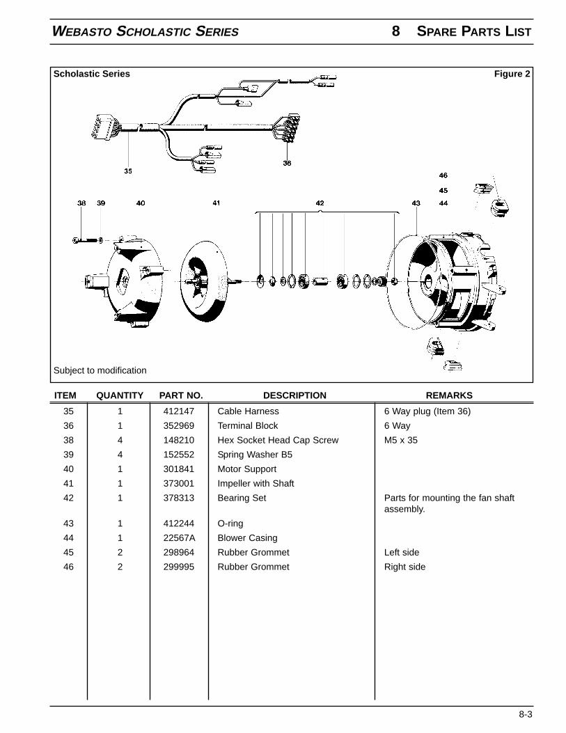
35 1 412147 Cable Harness 6 Way plug (Item 36)
36 1 352969 Terminal Block 6 Way
38 4 148210 Hex Socket Head Cap Screw M5 x 35
39 4 152552 Spring Washer B5
40 1 301841 Motor Support
41 1 373001 Impeller with Shaft
42 1 378313 Bearing Set Parts for mounting the fan shaftassembly.
43 1 412244 O-ring
44 1 22567A Blower Casing
45 2 298964 Rubber Grommet Left side
46 2 299995 Rubber Grommet Right side
ITEM QUANTITY PART NO. DESCRIPTION REMARKS
Figure 2Scholastic Series
Subject to modification
8 SPARE PARTS LIST WEBASTO SCHOLASTIC SERIES
8-4
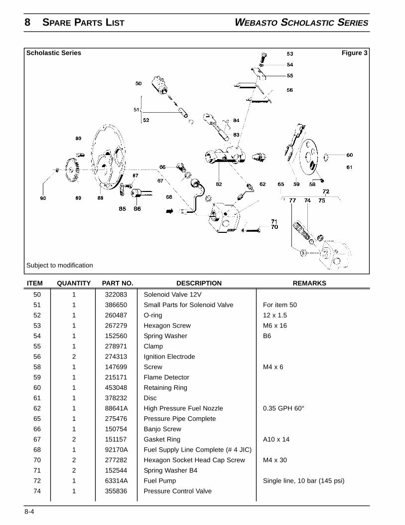
50 1 322083 Solenoid Valve 12V
51 1 386650 Small Parts for Solenoid Valve For item 50
52 1 260487 O-ring 12 x 1.5
53 1 267279 Hexagon Screw M6 x 16
54 1 152560 Spring Washer B6
55 1 278971 Clamp
56 2 274313 Ignition Electrode
58 1 147699 Screw M4 x 6
59 1 215171 Flame Detector
60 1 453048 Retaining Ring
61 1 378232 Disc
62 1 88641A High Pressure Fuel Nozzle 0.35 GPH 60°
65 1 275476 Pressure Pipe Complete
66 1 150754 Banjo Screw
67 2 151157 Gasket Ring A10 x 14
68 1 92170A Fuel Supply Line Complete (# 4 JIC)
70 2 277282 Hexagon Socket Head Cap Screw M4 x 30
71 2 152544 Spring Washer B4
72 1 63314A Fuel Pump Single line, 10 bar (145 psi)
74 1 355836 Pressure Control Valve
ITEM QUANTITY PART NO. DESCRIPTION REMARKS
Figure 3Scholastic Series
Subject to modification
WEBASTO SCHOLASTIC SERIES 8 SPARE PARTS LIST
8-5
75 1 310344 Filter Screen
77 1 260738 Gasket
80 2 488631 Screw with Washer
82 1 412198 Nozzle Holder
83 1 410799 Pre-heat Element 12V
84 1 19723B Holding Strap
85 1 298816 Bracket
86 1 104012 Pre-heat Thermostat
No Fig. 1 82399A Pre-heat Harness See item 186 for reference
87 4 488631 Screw with Washer
88 1 102861 Nozzle Holder Plate
89 1 371289 Straight Spur Gear
90 1 152390 Retaining Ring 6 x 0.7
No Fig. X 143820 ISOFLEX LDS 18 Special Hi-temp Grease In 100gtube. Use on fuel pump gears.
ITEM QUANTITY PART NO. DESCRIPTION REMARKS
8 SPARE PARTS LIST WEBASTO SCHOLASTIC SERIES
8-6
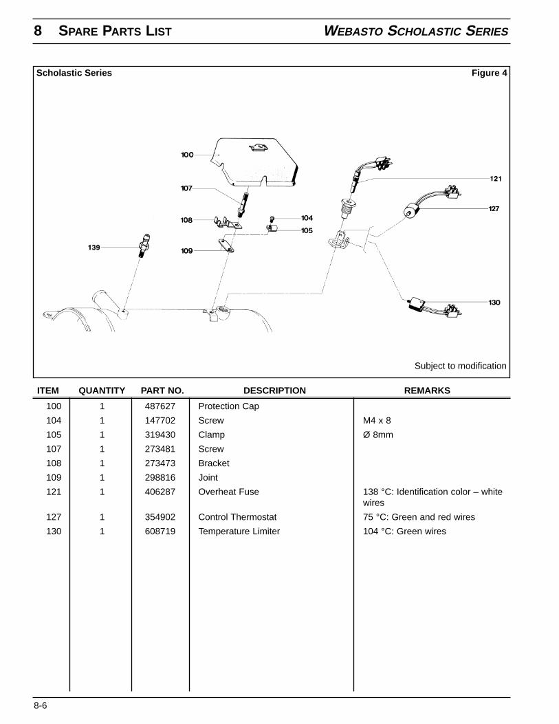
100 1 487627 Protection Cap
104 1 147702 Screw M4 x 8
105 1 319430 Clamp Ø 8mm
107 1 273481 Screw
108 1 273473 Bracket
109 1 298816 Joint
121 1 406287 Overheat Fuse 138 °C: Identification color – whitewires
127 1 354902 Control Thermostat 75 °C: Green and red wires
130 1 608719 Temperature Limiter 104 °C: Green wires
ITEM QUANTITY PART NO. DESCRIPTION REMARKS
Figure 4Scholastic Series
Subject to modification
WEBASTO SCHOLASTIC SERIES 8 SPARE PARTS LIST
8-7
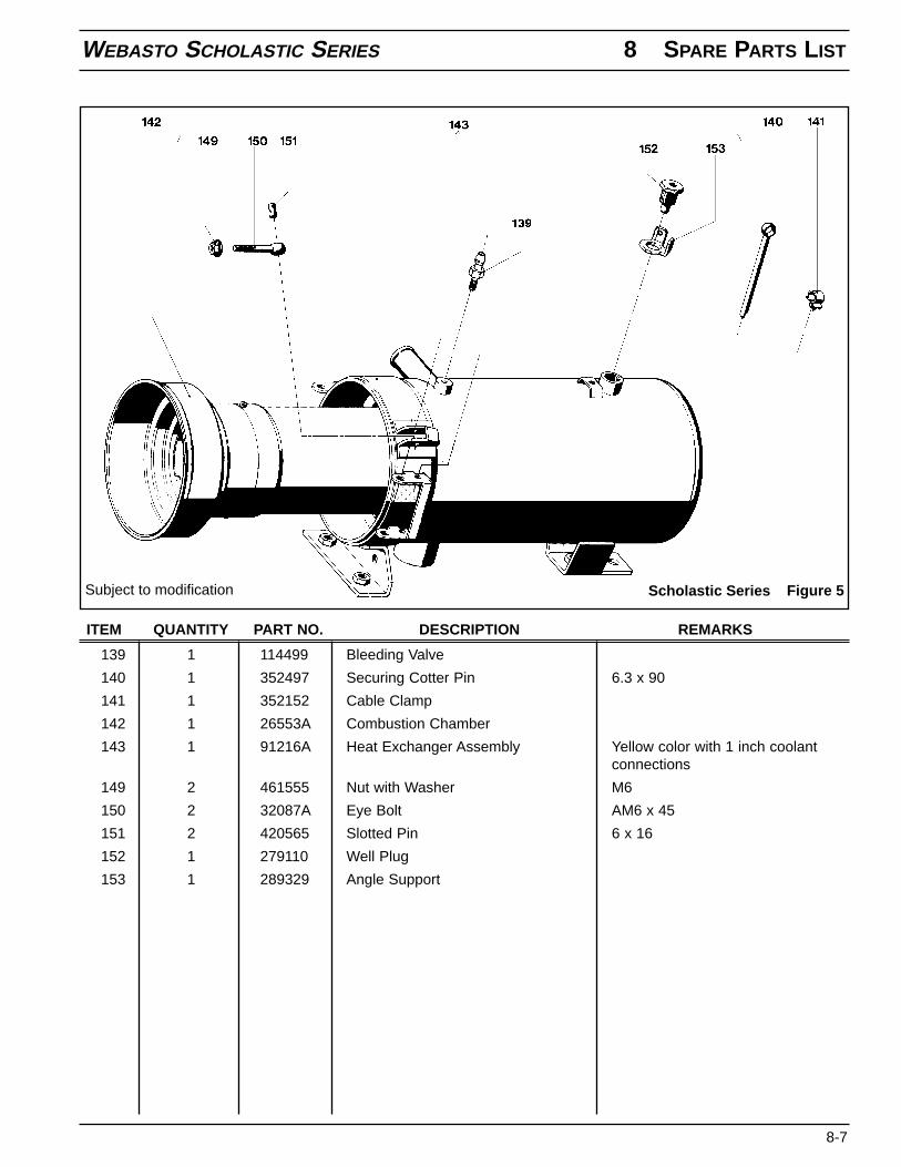
139 1 114499 Bleeding Valve
140 1 352497 Securing Cotter Pin 6.3 x 90
141 1 352152 Cable Clamp
142 1 26553A Combustion Chamber
143 1 91216A Heat Exchanger Assembly Yellow color with 1 inch coolantconnections
149 2 461555 Nut with Washer M6
150 2 32087A Eye Bolt AM6 x 45
151 2 420565 Slotted Pin 6 x 16
152 1 279110 Well Plug
153 1 289329 Angle Support
ITEM QUANTITY PART NO. DESCRIPTION REMARKS
Figure 5Scholastic SeriesSubject to modification
8 SPARE PARTS LIST WEBASTO SCHOLASTIC SERIES
8-8
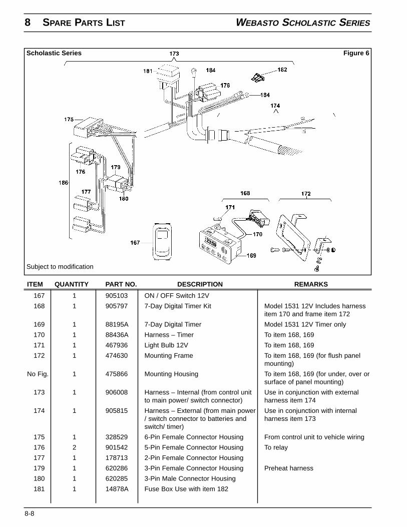
167 1 905103 ON / OFF Switch 12V
168 1 905797 7-Day Digital Timer Kit Model 1531 12V Includes harnessitem 170 and frame item 172
169 1 88195A 7-Day Digital Timer Model 1531 12V Timer only
170 1 88436A Harness – Timer To item 168, 169
171 1 467936 Light Bulb 12V To item 168, 169
172 1 474630 Mounting Frame To item 168, 169 (for flush panelmounting)
No Fig. 1 475866 Mounting Housing To item 168, 169 (for under, over orsurface of panel mounting)
173 1 906008 Harness – Internal (from control unit Use in conjunction with externalto main power/ switch connector) harness item 174
174 1 905815 Harness – External (from main power Use in conjunction with internal/ switch connector to batteries and harness item 173switch/ timer)
175 1 328529 6-Pin Female Connector Housing From control unit to vehicle wiring
176 2 901542 5-Pin Female Connector Housing To relay
177 1 178713 2-Pin Female Connector Housing
179 1 620286 3-Pin Female Connector Housing Preheat harness
180 1 620285 3-Pin Male Connector Housing
181 1 14878A Fuse Box Use with item 182
ITEM QUANTITY PART NO. DESCRIPTION REMARKS
Figure 6Scholastic Series
Subject to modification
WEBASTO SCHOLASTIC SERIES 8 SPARE PARTS LIST
8-9
182 2 24981A Fuse 15 Amp Use with item 181
182 1 103992 Fuse 20 Amp Use with item 181
183 7 178705 1-Pin Female Connector Housing
184 3 620295 Ring Connector Yellow M8
186 1 82399A Preheat Harness
No Fig. 1 900012 Inertia Switch
No Fig. 1 906026 Inertia Switch Harness
ITEM QUANTITY PART NO. DESCRIPTION REMARKS
8 SPARE PARTS LIST WEBASTO SCHOLASTIC SERIES
8-10
Figure 7Scholastic Series
Subject to modification
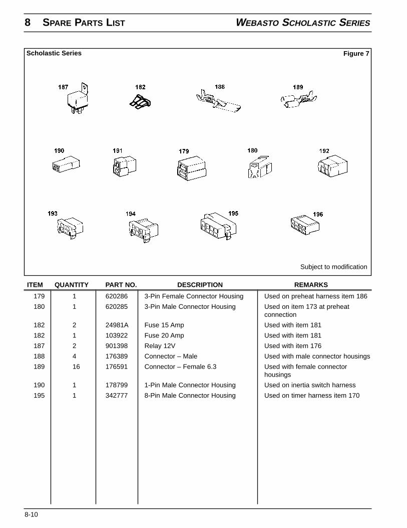
179 1 620286 3-Pin Female Connector Housing Used on preheat harness item 186
180 1 620285 3-Pin Male Connector Housing Used on item 173 at preheatconnection
182 2 24981A Fuse 15 Amp Used with item 181
182 1 103922 Fuse 20 Amp Used with item 181
187 2 901398 Relay 12V Used with item 176
188 4 176389 Connector – Male Used with male connector housings
189 16 176591 Connector – Female 6.3 Used with female connectorhousings
190 1 178799 1-Pin Male Connector Housing Used on inertia switch harness
195 1 342777 8-Pin Male Connector Housing Used on timer harness item 170
ITEM QUANTITY PART NO. DESCRIPTION REMARKS
WEBASTO SCHOLASTIC SERIES 8 SPARE PARTS LIST
8-11
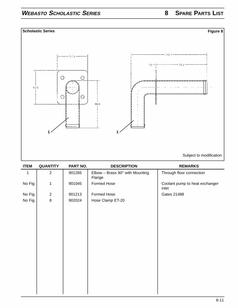
1 2 901265 Elbow – Brass 90° with Mounting Through floor connectionFlange
No Fig. 1 901045 Formed Hose Coolant pump to heat exchangerinlet
No Fig. 2 901213 Formed Hose Gates 21488
No Fig. 8 902024 Hose Clamp ET-20
ITEM QUANTITY PART NO. DESCRIPTION REMARKS
Figure 8Scholastic Series
Subject to modification
1 1
8 SPARE PARTS LIST WEBASTO SCHOLASTIC SERIES
8-12
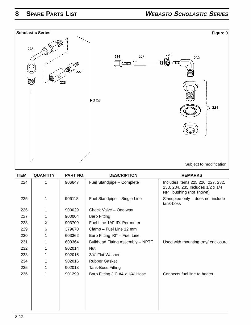
224 1 906647 Fuel Standpipe – Complete Includes items 225,226, 227, 232,233, 234, 235 Includes 1/2 x 1/4NPT bushing (not shown)
225 1 906118 Fuel Standpipe – Single Line Standpipe only – does not includetank-boss
226 1 900029 Check Valve – One way
227 1 900004 Barb Fitting
228 X 903709 Fuel Line 1/4” ID. Per meter
229 6 379670 Clamp – Fuel Line 12 mm
230 1 603362 Barb Fitting 90° – Fuel Line
231 1 603364 Bulkhead Fitting Assembly – NPTF Used with mounting tray/ enclosure
232 1 902014 Nut
233 1 902015 3/4” Flat Washer
234 1 902016 Rubber Gasket
235 1 902013 Tank-Boss Fitting
236 1 901299 Barb Fitting JIC #4 x 1/4” Hose Connects fuel line to heater
ITEM QUANTITY PART NO. DESCRIPTION REMARKS
Figure 9Scholastic Series
Subject to modification
WEBASTO SCHOLASTIC SERIES 8 SPARE PARTS LIST
8-13
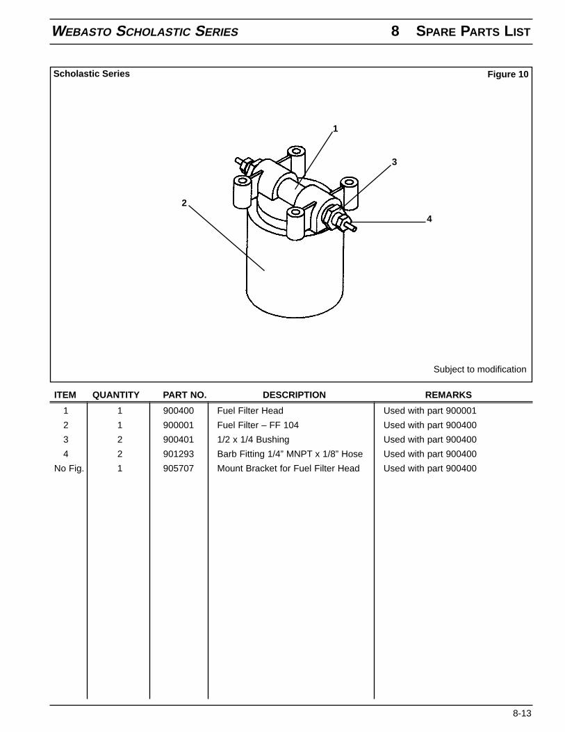
1 1 900400 Fuel Filter Head Used with part 900001
2 1 900001 Fuel Filter – FF 104 Used with part 900400
3 2 900401 1/2 x 1/4 Bushing Used with part 900400
4 2 901293 Barb Fitting 1/4” MNPT x 1/8” Hose Used with part 900400
No Fig. 1 905707 Mount Bracket for Fuel Filter Head Used with part 900400
ITEM QUANTITY PART NO. DESCRIPTION REMARKS
Figure 10Scholastic Series
Subject to modification
1
2
3
4
8 SPARE PARTS LIST WEBASTO SCHOLASTIC SERIES
8-14
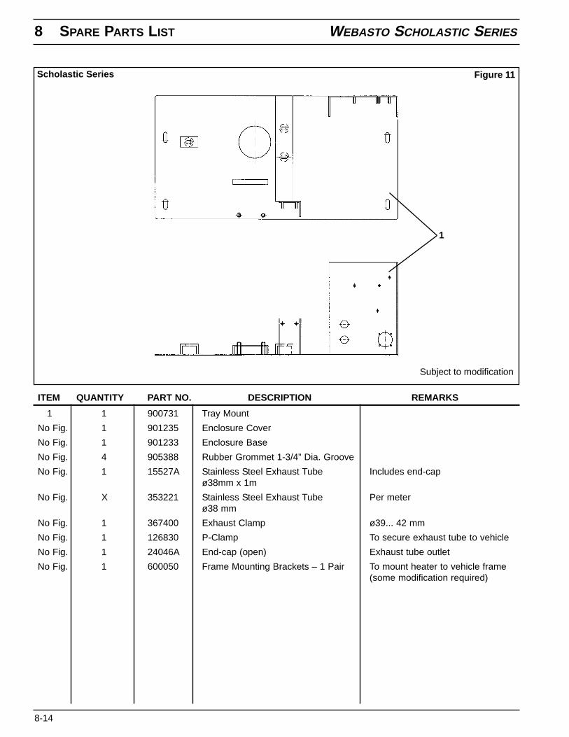
1 1 900731 Tray Mount
No Fig. 1 901235 Enclosure Cover
No Fig. 1 901233 Enclosure Base
No Fig. 4 905388 Rubber Grommet 1-3/4” Dia. Groove
No Fig. 1 15527A Stainless Steel Exhaust Tube Includes end-capø38mm x 1m
No Fig. X 353221 Stainless Steel Exhaust Tube Per meterø38 mm
No Fig. 1 367400 Exhaust Clamp ø39... 42 mm
No Fig. 1 126830 P-Clamp To secure exhaust tube to vehicle
No Fig. 1 24046A End-cap (open) Exhaust tube outlet
No Fig. 1 600050 Frame Mounting Brackets – 1 Pair To mount heater to vehicle frame(some modification required)
ITEM QUANTITY PART NO. DESCRIPTION REMARKS
Figure 11Scholastic Series
Subject to modification
1
WEBASTO SCHOLASTIC SERIES 8 SPARE PARTS LIST
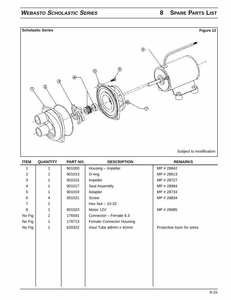
8-15
1 1 901000 Housing – Impeller MP # 28842
2 1 901013 O-ring MP # 28613
3 1 901015 Impeller MP # 28727
4 1 901017 Seal Assembly MP # 28984
5 1 901019 Adapter MP # 28733
6 4 901021 Screw MP # 28834
7 2 Hex Nut – 10-32
8 1 901023 Motor 12V MP # 28985
No Fig. 2 176591 Connector – Female 6.3
No Fig. 1 178713 Female Connector Housing
No Fig. 1 620322 Insul Tube ø8mm x 42mm Protective loom for wires
ITEM QUANTITY PART NO. DESCRIPTION REMARKS
Figure 12Scholastic Series
Subject to modification
8 SPARE PARTS LIST WEBASTO SCHOLASTIC SERIES
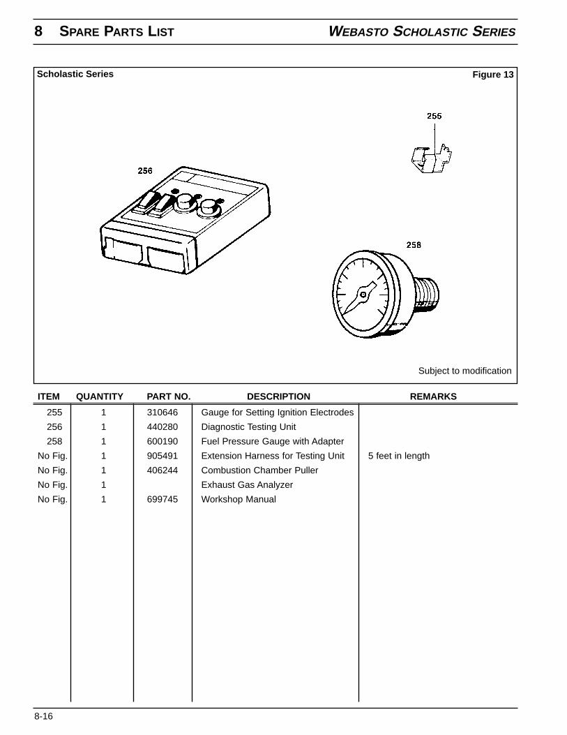
8-16
255 1 310646 Gauge for Setting Ignition Electrodes
256 1 440280 Diagnostic Testing Unit
258 1 600190 Fuel Pressure Gauge with Adapter
No Fig. 1 905491 Extension Harness for Testing Unit 5 feet in length
No Fig. 1 406244 Combustion Chamber Puller
No Fig. 1 Exhaust Gas Analyzer
No Fig. 1 699745 Workshop Manual
ITEM QUANTITY PART NO. DESCRIPTION REMARKS
Figure 13Scholastic Series
Subject to modification
The Scholastic SeriesSchool Bus Heater
Operating InstructionsInstallation InstructionsService Parts Listing
Webasto Thermosystems Inc.North America3333 John Conley DriveLapeer, MI 48446Phone (810) 245-2400Toll-free (800) HEATER-1Fax (810) 664-7720
Technical Assistance HotlineUSA: (800) 555-4518Canada: (800) 667-8900
www.webasto.comOrg. 2/2001 50000058A
For:
Conventional ModelTransit Model (Engine Front)Transit Model (Engine Rear)