Embed Size (px)
Citation preview
Simply the best! | 5
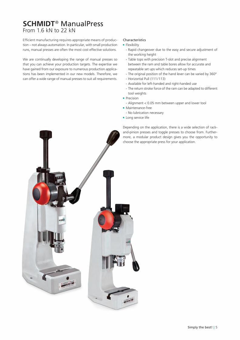
Efficient manufacturing requires appropriate means of produc-tion – not always automation. In particular, with small productionruns, manual presses are often the most cost effective solutions.
We are continually developing the range of manual presses so that you can achieve your production targets. The expertise we have gained from our exposure to numerous production applica-tions has been implemented in our new models. Therefore, we can offer a wide range of manual presses to suit all requirements.
Characteristics Flexibility
- Rapid changeover due to the easy and secure adjustment of the working height
- Table tops with precision T-slot and precise alignment between the ram and table bores allow for accurate and repeatable set ups which reduces set-up times
- The original position of the hand lever can be varied by 360° - Horizontal Pull (111 / 113) - Available for left-handed and right-handed use - The return stroke force of the ram can be adapted to different
tool weights Precision
- Alignment < 0.05 mm between upper and lower tool Maintenance-free
- No lubrication necessary Long service life
Depending on the application, there is a wide selection of rack-and-pinion presses and toggle presses to choose from. Further-more, a modular product design gives you the opportunity to choose the appropriate press for your application.
SCHMIDT ® ManualPressFrom 1.6 kN to 22 kN
6 | SCHMIDT® Presses
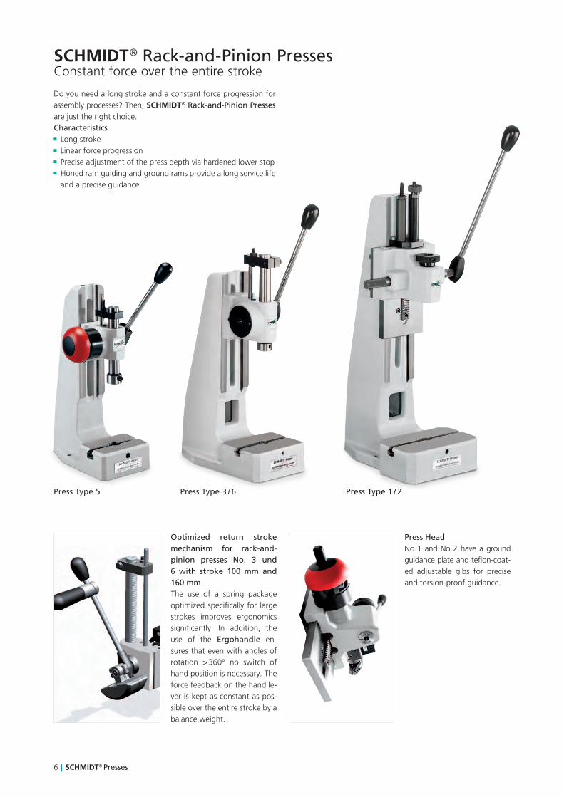
SCHMIDT ® Rack-and-Pinion PressesConstant force over the entire stroke
Do you need a long stroke and a constant force progression for assembly processes? Then, SCHMIDT ® Rack-and-Pinion Presses are just the right choice.Characteristics Long stroke Linear force progression Precise adjustment of the press depth via hardened lower stop Honed ram guiding and ground rams provide a long service life and a precise guidance
Press Type 5 Press Type 3 / 6 Press Type 1 / 2
Optimized return stroke mechanism for rack-and-pinion presses No. 3 und 6 with stroke 100 mm and 160 mmThe use of a spring package optimized specifically for large strokes improves ergonomics significantly. In addition, the use of the Ergohandle en-sures that even with angles of rotation > 360° no switch of hand position is necessary. The force feedback on the hand le-ver is kept as constant as pos-sible over the entire stroke by a balance weight.
Press HeadNo. 1 and No. 2 have a ground guidance plate and teflon-coat-ed adjustable gibs for precise and torsion-proof guidance.

0 0,5 1,0 1,5 2,0 2,5
100120140160180200
80604020
0
5 3+61+2
Simply the best! | 7
From 1.6 kN to 2.5 kN
M
SA
FK
C
B x T
L
Ø E
Ø D
B
10H9
17+1
7+1
9 ±
0.2
Press Type 5 5R 3 3R 6 6R 1 1R 2 2R
Press head type 5 5R 3 3R 3 3R 1 1R 1 1RNominal force kN 1.6 1.6 2.4 2.4 2.4 2.4 2.5 2.5 2.5 2.5Working stroke A mm 40 40 70 70 70 70 80 80 80 80
160 100 160 100 100 100 100 100Press head height S mm 240 240 350 350 350 350 400 400 400 400
350 350 350 350Throat depth C mm 65 65 86 86 86 86 86 86 86 86Ram bore Ø mm 10H7 10H7 10H7 10H7 10H7 10H7Collet (standard Ø 10) Ø mm 1 - 17 1 - 17 1 - 17 1 - 17Hand lever left • • • •Angle of rotation / mm stroke 4.1 ° 4.1 ° 3.2 ° 3.2 ° 3.2 ° 3.2 ° 2.2 ° 2.2 ° 2.2 ° 2.2 °
Max. weight of the upper tool 2) kg 1.5 1.0 2.5 2.0 2.5 2.0 1.0 1.0 1.0 1.0
Return stroke lock 1)
Minimum working stroke mm 17 18 18 26 26Locked position 1 mm bef. BDC 11.5 13 13 19.5 19.5Locked position 2 mm bef. BDC 3.5 4.5 4.5 7 7
Disengaging accuracy mm 0.06 0.07 0.07 0.08 0.08
Working height 3) FFrame No. 13 mm 55 - 200 55 - 200Frame No. 3 mm 75 - 220 75 - 220 120 - 260 120 - 260Frame No. 2 mm 100 - 355 100 - 355 145 - 360 145 - 360Frame No. 2-600 mm 200 - 600 200 - 600 200 - 600 200 - 600 245 - 650 245 - 650 245 - 650 245 - 650Frame No. 2-1000 mm 330 - 1030 330 - 1030 330 - 1030 330 - 1030 380 - 1080 380 - 1080 380 - 1080 380 - 1080Weight approx. kg 11 11 22 22 30 30 23 23 31 31
Accessories 5 5R 3 3R 6 6R 1 1R 2 2R
Mechanical counter
Throat depth frame (total depth)111 mm, 131 mm, 160 mm, 200 mm
Additional fixture mounting plate suitable for throat depth frame
Micrometer stop
Frame Overview Press Type Frame Height Mwithout height adj. (mm)
Table SizeB x T (mm)
Table BoreD (Ø mm)
Table HeightK (mm)
Mounting Surface B x L (mm)
No. 13 5 330 110 x 80 20H7 46 110 x 185No. 3 3, 1 400 150 x 110 20H7 60 150 x 260No. 2 6, 2 536 185 x 110 20H7 60 185 x 280No. 2-600 3, 6, 1, 2 810 200 x 160 20H7 98 200 x 290No. 2-1000 3, 6, 1, 2 1250 200 x 160 20H7 98 200 x 290
Options• Series with no additional charge Additional charge applies1) Adjustment of locking position on request2) The weight was determined with hand lever position 45° forward (guidelines)3) Typical values; can vary ± 3 mm due to casting and production
tolerancesOther available options
� Nickel plated – cast parts are electroless nickel plated, steel components black oxide finished, aluminum anodized, precision steel surfaces are untreated
� Custom Paint – press and column can be painted to customer’s color specification
� Bores for Adapting Tooling – customer specific sizes can be supplied
Pushing force (kN)
Forc
e at
the
han
d le
ver
(N)
Detailed dimensional drawings can be downloaded: www.schmidttechnology.de
30
M 8
10
No 3 + No 6: Ø 32 No 5: Ø 28
Ø 10H7

0,5 1,0 1,5 2,0 2,5 3,0 3,5 4,0 4,5 5,00 0 2 4 6 8 10 12 14 16
4,03,53,02,52,01,51,00,50
4,03,53,02,52,01,51,00,50
12
34
12
8 | SCHMIDT® Presses
SCHMIDT ® Toggle PressesThe high force at the end of stroke, just where it is important
Do you need a high force at the end of stroke for material trans-forming processes? Then, SCHMIDT ® Toggle Presses are just the right choice.
Characteristics High force at the end of stroke (see diagramm below) Honed bores and ground rams provide a long service life and
a precise guidance
Press Type 13RFZ Press Type 11 / 14 -17R
Pushing force (kN)
1 = No. 17 Force at the hand lever 200 N2 = No. 17 Force at the hand lever 120 N3 = No. 11, 14, 15, 16 Force at the hand lever 200 N4 = No. 11, 14, 15, 16 Force at the hand lever 120 N
Pushing force (kN)
1 = No. 13 Force at the hand lever 200 N2 = No. 13 Force at the hand lever 120 NSt
roke
bef
ore
plug
-in
posi
tion
of
the
togg
le (
mm
)
Stro
ke b
efor
e pl
ug-i
n po
siti
on o
f th
e to
ggle
(m
m)
Maximum force will be reached just before extended position

Simply the best! | 9
From 5 kN to 15 kN
Press Type1313F
13R13RF
1111F
11R11RF
1515F
15R15RF
1414F
14R14RF
1616F
16R16RF
1717F
Press head type13 - 4013F - 35
13R - 4013RF - 35
11 - 4511F - 35
11R - 4511RF - 35
11R - 4511F - 35
11R - 4511RF - 35
11 - 6011F - 50
11R - 6011RF - 50
11 - 6011F - 50
11R - 6011RF - 50
11 - 2011F - 20
Nominal force kN 5 5 12 12 12 12 12 12 12 12 15
Working stroke A mm4035
4035
4535
4535
4535
4535
6050
6050
6050
6050
2020
Throat depth C mm 65 65 86 86 86 86 86 86 86 86 86
Press head height S mm385400
385400
520540
520540
520540
520540
500520
500520
500520
500520
620640
Ram bore Ø mm 10H7 10H7 10H7 10H7 10H7 10H7 10H7 10H7 10H7 10H7 10H7Hand lever leftAngle of rotation 95 ° 95 ° 110 ° 110 ° 110 ° 110 ° 125 ° 125 ° 125 ° 125 ° 90 °Max. weight upper tool 3)
kg1.2 / 3.51.5 / 3
1.2 / 3.51.5 / 3
2 / 4.52.5 / 6
2 / 42 / 6
2 / 4.52.5 / 6
2 / 42 / 6
1.5 / 2.52 / 5
1.5 / 2.51.5 / 4
1.5 / 2.52 / 5
1.5 / 2.51.5 / 4
2.5 / -2.5 / -
Return stroke lock 1)
Minimum working stroke mm 25 20 20 24 24Locked position 1 mm bef. DC 13.5 12 12 14 14Locked position 2 mm bef. DC 1.5 1.5 1.5 1.5 1.5Disengaging accuracy mm 0.03 0.03 0.03 0.04 0.04Working height 4) F
Frame No. 13 mm65 - 18040 - 155
65 - 18040 - 155
Frame No. 3 mm75 - 21050 - 185
75 - 21050 - 185
90 - 22065 - 195
90 - 22065 - 195
65 - 20050 - 185
Frame No. 2 mm100 - 34580 - 325
100 - 34580 - 325
110 - 36085 - 335
110 - 36585 - 335
Frame No. 2-600 mm200 - 585175 - 560
200 - 585175 - 560
200 - 585175 - 560
200 - 585175 - 560
210 - 595185 - 570
210 - 595185 - 570
210 - 595185 - 570
210 - 595185 - 570
200 - 585175 - 560
Frame No. 2-1000 mm330 - 1020305 - 1000
330 - 1020305 - 1000
330 - 1020305 - 1000
330 - 1020305 - 1000
340 - 1030315 - 1010
340 - 1030315 - 1010
340 - 1030315 - 1010
340 - 1030315 - 1010
330 - 1020305 - 1000
Weight approx. kg 12 12 23 24 29 29 24 24 29 29 23
Accessories1313F
13R13RF
1111F
11R11RF
1515F
15R15RF
1414F
14R14RF
1616F
16R16RF
1717F
Mechanical counterThroat depth frame (total depth) 111 mm, 131 mmAdditional fixture mounting plate suitable for throat depth frame
Block clamping piece 2) • • • • •• • • •
Accessories1313F
13R13RF
1111F
11R11RF
1515F
15R15RF
1414F
14R14RF
1616F
16R16RF
1717F
Mechanical counterThroat depth frame (total depth) 111 mm, 131 mmAdditional fixture mounting plate suitable for throat depth frame
Block clamping piece 2) • • • • •• • • •
Options• Series with no additional charge Additional charge applies 1) Adjustment of locking position on request2) Stroke reduction about 10 mm by version with additional charge3) The weight was determined with hand lever position 45° forward
(guidelines)4) Typical values; can vary ± 3 mm due to casting and production
tolerances
Other available Options Nickel plated – Cast parts are electroless nickel plated, steel com-ponents black oxide finished, aluminum anodized, precision steel surfaces are untreated
Custom Paint – Press and column can be painted to customer’s color specification
Bores for Adapting Tooling – Customer specific sizes can be supplied
M
SA
FK
B
C
B x T
L
30
M 8
10
10H9
7+1
9 ±
0.2
17+1
Detailed dimensional drawings can be downloaded: www.schmidttechnology.de
Ø D
No. 113, 13: Ø 25No. 11, 14 - 17: Ø 32
Ø 10H7

0,5 1,0 1,5 2,0 2,5 3,0 3,5 4,0 4,5 5,00 0 2 4 6 8 10 12 14 16
4,03,53,02,52,01,51,00,50
4,03,53,02,52,01,51,00,50
12 12
10 | SCHMIDT® Presses
SCHMIDT ® Toggle Presses with Horizontal PullThe high force at the end of stroke, just where it is important
Ergonomic Press with hori-zontal pullWith press No. 113 and No. 111 the manual force is ap-plied by pulling the lever to-wards the body. This press is especially suitable for rapid production at small forces. We supply press No. 111 including the ergonomic handle (stand-ard scope of supply).
Do you need a high force at the end of stroke for material trans-forming processes? Then, SCHMIDT ® Toggle Presses are just the right choice.
Characteristics High force at the end of stroke (see diagramm below) Honed bores and ground rams provide a long service life and a precise guidance
Press Type 113RFZ Press Type 111RF
Pushing force (kN)
1 = No. 111 Force at the hand lever 200 N2 = No. 111 Force at the hand lever 120 NSt
roke
bef
ore
plug
-in
posi
tion
of
the
togg
le (
mm
)
Stro
ke b
efor
e pl
ug-i
n po
siti
on o
f th
e to
ggle
(m
m)
Maximum force will be reached just before extended position
1 = No. 113 Force at the hand lever 120 N2 = No. 113 Force at the hand lever 50 N

Simply the best! | 11
From 2.5 kN to 12 kN
Press Type113113F
113R113RF
111111F
111R111RF
Press head type 113113F
113R113RF
111 - 45111F - 50
111R - 45111RF - 50
Nominal force kN 2.5 2.5 12 12
Working stroke A mm2828
2828
4550
4550
Throat depth C mm 65 65 86 86
Press head height S mm170180
190200
215225
240250
Ram bore Ø mm 10H7 10H7 10H7 10H7Hand lever left - - - -Angle of rotation 80 ° 80 ° 90 ° 90 °
Max. weight upper tool 3) kg
1 / 30.6 / 3
0.5 / 2.50.6 / 3
2.5 / -3 / -
2.5 / -3 / -
Return stroke lock 1)
Minimum working stroke mm 22 24Locked position 1 mm bef. BDC 12 14Locked position 2 mm bef. BDC 0.5 1.5Disengaging accuracy mm 0.03 0.07Working height 4) F
Frame No. 13 mm50 - 16540 - 155
50 - 16540 - 155
Frame No. 3 mm120 - 205105 - 195
120 - 205105 - 195
Frame No. 2 mm120 - 345105 - 335
120 - 345105 - 335
Frame No. 2-600 mm200 - 580185 - 570
200 - 580185 - 570
Frame No. 2-1000 mm330 - 1020310 - 1000
330 - 1020310 - 1000
Weight approx. kg 11 11 28 28
Accessories 113113F
113R113RF
111111F
111R111RF
Mechanical counter
Throat depth frame (total depth)111 mm, 131 mm
Additional fixture mounting plate suitable for throat depth frame
Block clamping piece 2) • • • •
Frame Overview Press TypeFrame Height
M (mm)Table SizeB x T (mm)
Table BoreD (Ø mm)
Table HeightK (mm)
Mounting Surface B x L (mm)
No. 13 113 475 110 x 80 20H7 46 110 x 185
No. 3 111 540 150 x 110 20H7 60 150 x 260
No. 2 111 700 185 x 110 20H7 60 185 x 280
No. 2-600 111 974 200 x 160 20H7 98 200 x 290
No. 2-1000 111 1410 200 x 160 20H7 98 200 x 290
Options• Series with no additional charge Additional charge applies1) Adjustment of locking position on request2) Stroke reduction about 10 mm by version with additional charge3) The weight was determined with hand lever position 45° back
(guidelines)4) Typical values; can vary ± 3 mm due to casting and production
tolerances
Other available options Nickel plated – Cast parts are electroless nickel plated, steel components black oxide finished, aluminum anodized, precision steel surfaces are untreated
Custom Paint – Press and column can be painted to customer’s color specification
Bores for Adapting Tooling – Customer specific sizes
M
FK
S
B x T
30
M 8
10
17+1
7+1
9 ±
0.2
B
L
Detailed dimensional drawings can be downloaded: www.schmidttechnology.de
10H9
C
No. 113: Ø 25No. 111: Ø 32
Ø 10H7
Ø D

4,03,53,02,52,01,51,00,50
4,03,53,02,52,01,51,00,50
0 4 6 10 14 16 18 20 228 12 240 2 6 10 12 144 8 16
1212
12 | SCHMIDT® Presses
SCHMIDT ® Toggle Presses with Square RamOptimum guidance and anti-rotation
Do you need a high force at the end of stroke for material-transforming processes? Then, SCHMIDT ® Toggle Presses are just the right choice.
Characteristics High force at the end of stroke Square ram is anti-rotational (no die sets required) Fully adjustable, play-free teflon-lined gibs
Press Type 11 VRFZ 13 VRFZ 14 VRFZ
Press Type 15 VF 16 VF
Press Type 19 VF
1 = No. 11, 14, 15, 16 Force at the hand lever 200 N2 = No. 11, 14, 15, 16 Force at the hand lever 120 NNo. 13 see on page 8
1 = No. 19 Force at the hand lever 200 N2 = No. 19 Force at the hand lever 120 N
Maximum force will be reached just before extended position
Pushing force (kN)
Stro
ke b
efor
e pl
ug-in
pos
ition
of
the
togg
le (m
m)
Pushing force (kN)
Stro
ke b
efor
e pl
ug-in
pos
ition
of
the
togg
le (m
m)

Simply the best! | 13
From 5 kN to 22 kN
Press Type13 V13 VF
13 VR13 VRF
11 V11 VF
15 V15 VF
11 VR11 VRF
15 VR15 VRF
14 V14 VF
16 V16 VF
14 VR14 VRF
16 VR16 VRF
19 V19 VF
19 VR19 VRF
Press head type 13V-4013VF-40
13VR-4013VRF-40
11V-4511VF-45
11V-4511VF-45
11VR-4511VRF-45
11VR-4511VF-45
11V-6011VF-60
11V-6011VF-60
11VR-6011VRF-60
11VR-6011VRF-60
19V-40 1) 19VR-40 1)
Nominal force kN 5 5 12 12 12 12 12 12 12 12 22 22
Working stroke A mm40 40 45 45 45 45 60 60 60 60 40 4040 40 45 45 45 45 60 60 60 60 40 40
Throat depth C mm 65 65 86 86 86 86 86 86 86 86 131 131
Press head height S mm385 385 510 510 510 510 510 510 510 510 620 620400 400 530 530 530 530 530 530 530 530 620 620
Ram bore Ø mm 10H7 10H7 10H7 10H7 10H7 10H7 10H7 10H7 10H7 10H7 20H7 20H7Hand lever left • •Angle of rotation 95° 95° 110° 110° 110° 110° 125° 125° 125° 125° 175° 175°
Max. weight top tool 3) kg1.2 / 4 1.2 / 4 1.6 / 4.2 1.6 / 4.2 1.6 / 4.2 1.6 / 4.2 1 / 3.5 1 / 3.5 1 / 3.5 1 / 3.5 2 / - 2 / -
2 / 3.5 2 / 3.5 2 / 5 2 / 5 2 / 5 2 / 5 1 / 3.5 1 / 3.5 1 / 3.5 1 / 3.5 2 / - 2 / -
Return stroke lock 2)
Minimum working stroke mm 26 20 20 28 28 10Locked position 1 mm bef. BDC 14.5 12 12 14 14 4.5Locked position 2 mm bef. BDC 1.5 1.5 1.5 1.5 1.5 0.9 Disengaging accuracy mm 0.03 0.03 0.03 0.04 0.04 0.02Working height 4) F
Frame No. 13 mm65 - 180 65 - 18050 - 165 50 - 165
Frame No. 3 mm80 - 210 80 - 210 80 - 210 80 - 21060 - 190 60 - 190 60 - 190 60 - 190
Frame No. 2 mm105 - 350 105 - 350 105 - 350 105 - 35085 - 330 85 -330 85 - 330 85 - 330
Frame No. 2-600 mm200 - 585 200 - 585 210 - 590 210 - 590185 - 570 185 - 570 195 - 575 195 - 575
Frame No. 2-1000 mm330 - 1020 330 - 1020 340 - 1030 340 - 1030315 - 1000 315 - 1000 325 - 1015 325 - 1015
Frame No. 19 mm 90 - 220 90 - 220Frame No. 19-400 mm 160 - 400 160 - 400Frame No. 19-500 mm 260 - 550 260 - 550Weight approx. kg 12 12 24 32 24 32 24 32 24 32 85 85
Accessories13 V13 VF
13 VR13 VRF
11 V11 VF
15 V15 VF
11 VR11 VRF
15 VR15 VRF
14 V14 VF
16 V16 VF
14 VR14 VRF
16 VR16 VRF
19 V19 VF
19 VR19 VRF
Mechanical counter
Throat depth frame 111 mm,131 mm
Throat depth frame 151 mm
Additional fixture mounting plate suitable for throat depth frame
Frame Overview Press TypeFrame Height
M (mm)Table SizeB x T (mm)
Table BoreD (Ø mm)
Table HeightK (mm)
Mounting Surface B x L (mm)
No. 13 13 475 110 x 80 20H7 46 110 x 85No. 3 11, 14 540 150 x 110 20H7 60 150 x 260No. 2 15, 16 700 185 x 110 20H7 60 185 x 280
No. 2-600 15, 16 974 200 x 160 20H7 98 200 x 290No. 2-1000 15, 16 1410 200 x 160 20H7 98 200 x 290No. 19 19 640 200 x 160 25H7 112 200 x 370No. 19-400 19 840 250 x 200 40H7 145 250 x 460No. 19-500 19 1000 250 x 200 40H7 145 250 x 480
Options
• Series with no additional charge Additional charge applies1) Special strokes 12 mm and 50 mm on request2) Adjustment of locking position on request3 The weight was determined with hand lever position 45° forward (guidelines)4) Typical values; can vary ± 3 mm due to casting and production tolerances
Other available options Nickel plated – Cast parts are electroless nickel plated, steel components black oxide finished, aluminum anodized, precision steel surfaces are untreated
Custom Paint – Press and column can be painted to customer’s color specification
Bores for Adapting Tooling – Customer specific sizes
M
A
FK
B
C
B x T
S
10H9
17+1
7+1 9
± 0
.2
L
Detailed dimensional drawings can be downloaded: www.schmidttechnology.de
Ø D

2
3
1
5
2
1
4
14 | SCHMIDT® Presses
The return stroke lock guarantees reaching the required pressing depth with every stroke
1 TDC (Top Dead Center) position
2 First locking position: Loose tools can still be aligned
3 Second locking position before BDC (Bottom Dead Center). From here you can only continue to BDC.
4 After reaching BDC (Bottom Dead Center) by completing the stroke the return stroke lock is released. This guarantees a repeatable BDC and thus a constant press depth
5 The emergency button releases the locking function in any position
The micrometer screw serves as stop for the rack and pinion pressesA micrometer adjustable stop specially developed for presses for the fine adjustment of the BDC. The robust and precise design ensures the repeatability of the stop, no matter how many strokes are taken.
Fine adjustment with micrometer scale for Toggle PressesBy loosening the tensioning screw 1 and turning the adjust-ing nut 2 with the same tool, the setting of the BDC can be adjusted infinitely. The adjustment in a range of 1⁄100 of mm is reached rapidly and precisely.
SCHMIDT ® ManualPressOptions suitable for your application
Simply the best! | 15
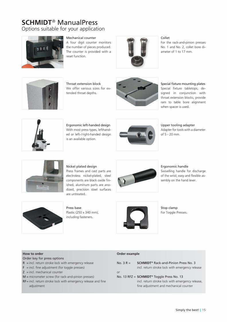
SCHMIDT ® ManualPressOptions suitable for your application
Mechanical counterA four digit counter monitors the number of pieces produced. The counter is provided with a reset function.
ColletFor the rack-and-pinion presses No. 1 and No. 2, collet bore di-ameter of 1 to 17 mm.
Upper tooling adapterAdapter for tools with a diameter of 5 - 20 mm.
Throat extension blockWe offer various sizes for ex-tended throat depths.
Special fixture mounting platesSpecial fixture tabletops, de-signed in conjunction with throat extension blocks, provide ram to table bore alignment when spacer is used.
Ergonomic handleSwivelling handle for discharge of the wrist; easy and flexible as-sembly on the hand lever.
Nickel plated designPress frames and cast parts are electroless nickel-plated, steel components are black oxide fin-ished, aluminum parts are ano-dized, precision steel surfaces are untreated.
Ergonomic left-handed designWith most press types, lefthand-ed or left- / right-handed design is an available option.
Press basePlastic (250 x 340 mm),including fasteners.
Stop clamp For Toggle Presses.
How to orderOrder key for press optionsR = incl. return stroke lock with emergency releaseF = incl. fine adjustment (for toggle presses)Z = incl. mechanical counterM = micrometer screw (for rack-and-pinion presses)RF = incl. return stroke lock with emergency release and fine adjustment
Order example
No. 3 R = SCHMIDT ® Rack-and-Pinion Press No. 3 incl. return stroke lock with emergency releaseorNo. 13 RFZ = SCHMIDT ® Toggle Press No. 13 incl. return stroke lock with emergency release, fine adjustment and mechanical counter