Embed Size (px)
Citation preview


________________________________________________________________________________________________ESD 1.6-104-r0 Check the LCLS Project website to verify 2 of 12 that this is the correct version prior to use.
1. Introduction: The AMO experiment at LCLS will use samples of gaseous atoms, molecules, clusters and their ions as targets to study the interaction of the x-ray FEL beam with simple isolated forms of matter. Neutral species will be introduced into the interaction region in the form of a skimmed supersonic gas jet to provide a collimated sample beam that will cross the FEL beam at its focus. The sample will be provided over a range of densities from single atoms, molecules or clusters in the interaction volume coincident with the FEL pulse for experiments where low signal rates are required, ion momentum spectroscopy for example, up to several hundred atoms, molecules or clusters in the same volume when larger integrated signals are required. This document describes the sample introduction system in detail together with calculations of required performance parameters.
Figure 1: Schematic of the gas jet system. 2. Interaction Volume The interaction volume is defined by the intersections of the volumes of: 1) the FEL beam, 2) the region where the sample has appreciable density, and 3) the acceptance of the particular detector(s) being used. Ideally the acceptance volume of the detector will be

________________________________________________________________________________________________ESD 1.6-104-r0 Check the LCLS Project website to verify 3 of 12 that this is the correct version prior to use.
matched to or larger than the other two factors, so will be neglected any further here. It is worth noting, however, that the acceptance volume of the detector can be used to select a “slice” of the intersection of the other two contributions to the interaction volume, i.e. to select a region of highest beam intensity. This can be accomplished using a suitable aperture over the entrance to the detector.
Figure 2: Ideallized sketch of the interaction region formed by the intersection of the FEL beam, extents shown in red, and a jet of gas of width l. Note that the FEL beam is focused to a width w though an angle s' from a width d at edges of the interaction region. A simple geometric consideration of the focusing of the FEL beam (considering it as a circular aperture source of size σ with divergence σ’) by optics a distance r away from the source focusing the beam to a point r’ beyond the optics is shown above in Figure 2. This sketch illustrates why a narrow collimated gas jet is preferred over an effusive source that rapidly diverges from the nozzle. In the case of an effusive jet, the length of the interaction region along the converging and diverging FEL beam is likely greater than that of a collimated beam, sampling a broader range of power densities of the FEL beam. 3. Sample Source Nozzle: Both continuous and pulsed supersonic sample sources are compatible with the requirements of the LCLS AMO experiment. In most circumstances the pulsed jet will be used, but in particular circumstances it may be preferable to use a continuous beam jet. The gas introduction system will be compatible with both methods of introducing the sample.
3.1. Continuous Beam Nozzle
A continuous source is formed by expanding gas from a relatively high pressure through a small orifice. Under the proper pressure conditions a supersonic expansion is formed as the gas expands from the orifice into the vacuum. While a continuous source will function appropriately with the LCLS a pulsed source will usually be preferable due to reduced pumping speed requirements. A continuous beam source might be appropriate for some specific applications, and it would therefore be prudent to maintain the capability for its use in the AMO instrument. Practically, the design of majority of the specifications and design for the gas jet system are compatible with both continuous and pulsed nozzles, with only a change of the nozzle at the end of the sample manipulator required. 3.2.1. The nozzle for a continuous beam source is typically created using a circular
electron microscope aperture with sizes ranging from 10 – 200 μm, depending

________________________________________________________________________________________________ESD 1.6-104-r0 Check the LCLS Project website to verify 4 of 12 that this is the correct version prior to use.
on the gaseous species, tolerable background pressure and whether or not clusters are desired.
3.2.2. The aperture disk, typically platinum or molybdenum is mounted to the end of a tube carrying the gas of interest with a metal to metal seal.
3.2.3. The output characteristics of the continuous beam nozzle are dynamically controlled simply via the backing pressure of the gas. The gas handling system is described in greater detail below.
3.2.4. Finally, cooling of the nozzle to liquid nitrogen (or even liquid helium) temperatures may be required. This can be achieved with fluids transported to the nozzle tip or with a thermal link to an appropriate temperature reservoir. Note that the pressure in the first skimmer chamber is often quite high (up to 10-3 Torr) and thermal loading of the linkage can be a problem at these high pressures.
3.2. Pulsed Beam Nozzle
A pulsed source is the preferred method for introducing sample gases into the interaction region as it increases the effective pumping speed in the skimmer chamber due to the low duty cycle of the LCLS. A pulsed gas source is created using a fast valve to modulate the gas flow into the nozzle. The nozzle is typically formed by the seat of the plunger used to form the valve. The expected gain in pumping capacity is given by the duty cycle of the valve: ( )
1P rate opening timeΔ = × . With a 100 μs opening
duration and 120 Hz rate, a pulsed valve can increase the pumping capacity of the background in the skimmer chamber by 83 times (even greater gains are realized if shorter pulses are used). Several different designs of pulsed gas valve are in use in the chemical dynamics and molecular spectroscopy communities: solenoidal valves; piezoelectric valves, etc. As a baseline, the AMO experiment will use the piezoelectric valve described by Proch and Trickl (Proch and Trickl 1989) due to the extensive (and positive) experience with this design in the Chemical Dynamics group at LBNL and elsewhere at UC Berkeley. Designs for the valve have been obtained from the Chemical Dynamics group at the ALS and will be used to fabricate the required parts. An alternative design currently being investigated is the Even-Lavie valve (Even, Jortner et al. 2000) which is capable of shorter opening times (quoted down to 15 μs). The gas jet system is modular, so it should be reasonably simple to change between different pulsed valves if necessary.

________________________________________________________________________________________________ESD 1.6-104-r0 Check the LCLS Project website to verify 5 of 12 that this is the correct version prior to use.
Figure 3: Schematic of the Proch Tickl supersonic gas jet valve (Proch and Trickl 1989). The valve is actuated by a piez disk translater (p.286.27) .
3.2.1. The valve must operate reproducibly at the frequency of the LCLS, typically
120 Hz, but also possibly 10, 30 and 60 Hz. 3.2.2. The opening time of the valve should be externally controllable and less than
100 μs. 3.2.3. The nozzle of the valve should be readily changeable, with a minimal number
of parts to be changed/remanufactured, in order to accommodate different sample conditions.
3.2.4. The leak rate of the valve should be low enough to maintain a base pressure of 10-7 Torr in the skimmer chamber.
3.2.5. Backing pressures of up to ten atmospheres should be safely accommodated by the valve body/plunger.
3.2.6. Operation of the valve at liquid nitrogen temperatures should be eventually accommodated
3.3. Sample Nozzle Mounting:
The sample nozzle will be mounted on a remotely controlled XYZ manipulator attached to a flange that connects to the skimmer vacuum chamber to allow optimization of the alignment of the gas jet with the skimmer(s) and interaction region. The distance of the nozzle from the skimmer is also an important dimension of control as the throughput of the system can depend sensitively on this distance and it can be different for different species.
3.3.1. The range of controllable motion in X and Y (transverse to the gas beam propogation direction) should be at least ± 10mm with a reproducibility and stability of 10 μm.

________________________________________________________________________________________________ESD 1.6-104-r0 Check the LCLS Project website to verify 6 of 12 that this is the correct version prior to use.
3.3.2. The range of controllable motion in the Z direction (the direction of gas jet propagation) should be ± 50mm with reproducibility and stability of 50 μm.
3.3.3. If required to ensure proper alignment, mechanical adjustment of the nozzle to bring it within the ranges of motion of the manipulators should be provided as an adjustment to be made on the bench.
3.3.4. Care should be taken to ensure that the nozzle cannot contact the fragile skimmer cone at the extremes of its motion.
3.3.5. Gas supply and electrical connections to operate the pulsed valve, in vacuum motors and position sensors (if used) and monitor the nozzle temperature should be provided on the flange mounting the manipulator permitting removal of the entire assembly.

_______________________________________________________________________________________________________ESD 1.6-104-r0 Check the LCLS Project website to verify 7 of 12 that this is the correct version prior to use.
4. Gas supply system The gas nozzle is supplied with gas from an external source through a pipe that passes through the vacuum chamber wall. At times high backing pressures will be required to cool internal degrees of freedom or aggregate the sample into clusters in the supersonic expansion. Pressure relief valve will not be useful due to this high pressure requirement. Careful consideration of safety and operational modes will need to be applied to the design of the gas supply system. All components of the gas supply system inside the vacuum system must also be designed to withstand the highest pressure required. Typically commercial Swagelock and VCR fitting are used which are to adequate pressures.
4.1. Supply valve
The first element of the gas supply system external to the vacuum chamber will be an interlocked shut off valve.
4.1.1. the valve should be a pneumatically actuated normally closed valve. 4.1.2. the valve should have commercial VCR or Swagelok fittings to facilitate its
replacement. 4.1.3. the valve should be interlocked to the normal operation of the vacuum system of the
skimmer chamber – i.e. the pumps should be fully operational and the pressure reading of the chamber in the nominal operation range before it can be opened.
4.1.4. When the bypass valve (see below) is opened, the supply valve must be closed. 4.1.5. The valve should not be openable if the front valve of the chamber is open, but
should remain open if opened before the front valve is opened.
4.2. Pump out
A vacuum pump should be dedicated for use with the gas supply system to pump it out in preparation for using a new gas sample. The pump will be used to evacuate the system before pressurizing it with a new sample or to remove the sample from the system at the conclusion of an experiment.
4.2.1. the pump should be an oil free system with a base pressure of <10-5 Torr. 4.2.2. A pneumatically actuated valve (or valves) connecting the pump to the gas supply
system should be capable of withstanding the pressure of the supply system. 4.2.3. The pump should be exhausted to an externally evacuated exhaust system to prevent
contamination of the hutch environment with the sample gas. 4.2.4. An expansion chamber should be fitted between the pump-out valve and the pump
to prevent over-pressurizing the pump body.
4.3. Pressure regulation
Samples of gas will typically either be purchased as a bottle of the pure gas, i.e. Neon, or prepared as a mixture of a sample in a carrier gas, i.e. 2% CO2 in He. Regardless, the samples will be in high pressure bottles that will be connected to the gas supply system through a pressure regulator. A manual regulator will first be used to reduce to supply pressure to an

_______________________________________________________________________________________________________ESD 1.6-104-r0 Check the LCLS Project website to verify 8 of 12 that this is the correct version prior to use.
appropriate level from the high pressure sample bottle. A digitally controlled pressure regulator will then be used to maintain the pressure of the sample gas at the desired level at the nozzle.
4.3.1. several different manual regulators with different CGA fittings and pressure ranges will need to be stocked to connect the sample bottle to the gas supply system via commercial tube fittings (i.e. Swagelok).
4.3.2. a computer controlled pressure regulating valve and pressure sensor will be fitted downstream of the manual regulator.
4.3.3. different pressure regulating valves (or at least sensors) may be required to cover the full range of desired sample pressures delivered to the nozzle.
4.3.4. the pressure sensor with the appropriate range downstream of the regulating valve should be monitored and recorded during an experimental run if it is not already a part of the pressure regulating valve.
4.4. Safety
Safety considerations are an important factor in the design of the gas supply system. Only commercial products with appropriate pressure ratings will be used in the gas supply system external to the skimmer vacuum chamber. The system will require the approval of the safety committee at SLAC before proceeding from design to fabrication and again before it can be put into operation.
5. Skimmer chamber Gas emerging from the nozzle in a supersonic jet is forward focused, relative to that emerging from an effusive jet, by approximately a factor of two. This results in an increased beam brightness in a given solid angle in the forward direction, but not by a large factor. Most of the gas in the beam is not moving in a direction that will result in it occupying the interaction region and hence it is best to remove that gas from the beam. That is accomplished using a skimmer with a small aperture on the axis between the nozzle and the interaction region. Gas which does not pass though the small skimmer aperture must be removed from the skimmer chamber volume, otherwise it will result in increased background pressure that will eventually interact with the supersonic beam, scattering it out of the acceptance of the skimmer aperture. The nozzle of the gas jet is susceptible to clogging due to small particles in the gas supply line, or icing due to cooling from the supersonic expansion. It can therefore be necessary to access the nozzle frequently. A means of isolating the skimmer chamber from the main experimental chamber, allowing only the skimmer chamber to be vented will expedite pump down and return to operations. When very low sample densities are required in the interaction region together with high sample pressure at the nozzle, i.e. when trying to have only one or a few atoms or clusters in the interaction region at a time during the FEL pulse, multiple stages of skimmers are required. The first skimmer chamber reduces the background density to ensure a free flight path for the sample atoms/molecules/clusters in the second chamber where the background pressure is much lower. The second (or subsequent) aperture serves to select a narrow solid angle of the beam emerging from the nozzle and hence reduce the density of the sample in the interaction region to the desired level.
_______________________________________________________________________________________________________ESD 1.6-104-r0 Check the LCLS Project website to verify 9 of 12 that this is the correct version prior to use.
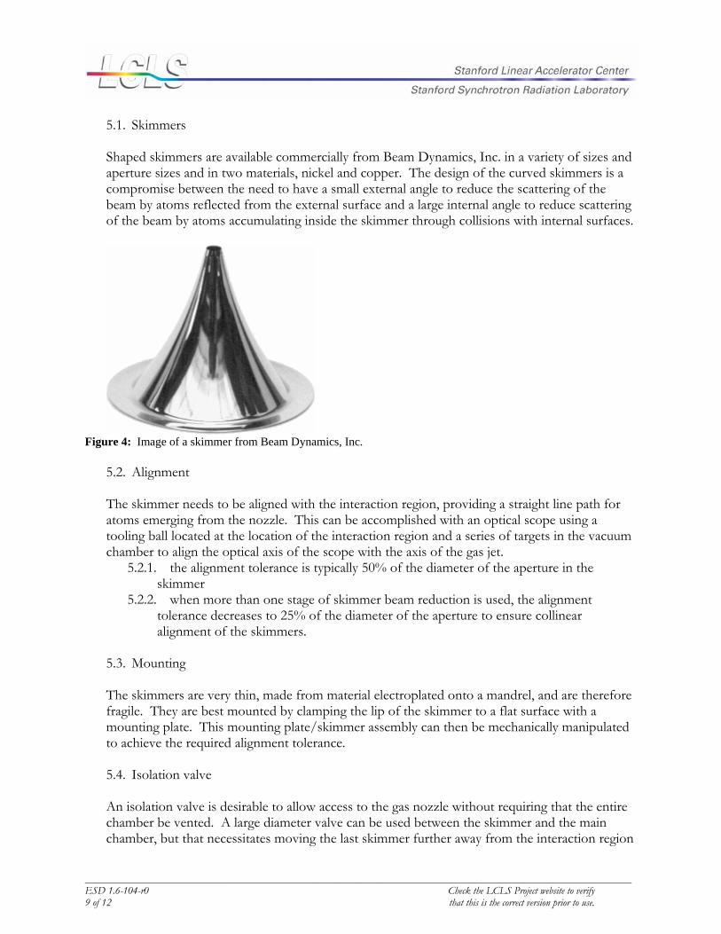
5.1. Skimmers
Shaped skimmers are available commercially from Beam Dynamics, Inc. in a variety of sizes and aperture sizes and in two materials, nickel and copper. The design of the curved skimmers is a compromise between the need to have a small external angle to reduce the scattering of the beam by atoms reflected from the external surface and a large internal angle to reduce scattering of the beam by atoms accumulating inside the skimmer through collisions with internal surfaces.
Figure 4: Image of a skimmer from Beam Dynamics, Inc.
5.2. Alignment
The skimmer needs to be aligned with the interaction region, providing a straight line path for atoms emerging from the nozzle. This can be accomplished with an optical scope using a tooling ball located at the location of the interaction region and a series of targets in the vacuum chamber to align the optical axis of the scope with the axis of the gas jet.
5.2.1. the alignment tolerance is typically 50% of the diameter of the aperture in the skimmer
5.2.2. when more than one stage of skimmer beam reduction is used, the alignment tolerance decreases to 25% of the diameter of the aperture to ensure collinear alignment of the skimmers.
5.3. Mounting
The skimmers are very thin, made from material electroplated onto a mandrel, and are therefore fragile. They are best mounted by clamping the lip of the skimmer to a flat surface with a mounting plate. This mounting plate/skimmer assembly can then be mechanically manipulated to achieve the required alignment tolerance.
5.4. Isolation valve
An isolation valve is desirable to allow access to the gas nozzle without requiring that the entire chamber be vented. A large diameter valve can be used between the skimmer and the main chamber, but that necessitates moving the last skimmer further away from the interaction region

_______________________________________________________________________________________________________ESD 1.6-104-r0 Check the LCLS Project website to verify 10 of 12 that this is the correct version prior to use.
in order to provide clearance for the valve. A more appropriate solution has been identified, an in vacuum gate valve from VAT. The valve gate and body are connected to the skimmer chamber while the actuating mechanism is attached to the outside of the main chamber. A linkage with appropriate stiffness and degrees of freedom is used to connect the two in vacuum.
5.4.1. the gate valve should seal sufficiently to allow venting the skimmer chamber without appreciable pressure increase in the interaction region chamber
5.4.2. the valve should provide sufficient clearance so as to not interfere with the beam emerging from the skimmer when open
5.4.3. the valve should be made of nonmagnetic materials and further isolated from the interaction region by additional magnetic shielding.
5.5. Bypass valve
When venting the entire chamber, including both the interaction region chamber and the skimmer chamber, care should be taken to ensure that a large differential pressure does not develop across the skimmer. While it is likely that the skimmer will survive mechanically, its alignment is likely to be changed unless a very stiff alignment mechanism is used. The easiest way to ensure that the two chambers remain at the same pressure when venting or pumping down is to open a large conductance path around the skimmer.
5.5.1. the bypass valve should be opened before venting the chambers and remain open during the venting procedure.
5.5.2. The chamber should be isolated from all upstream and downstream chambers when the bypass valve is open and all high voltages should be disabled.
5.5.3. The bypass valve can be closed only when the pumps reach their operational speeds or the pressures in both the chambers are below 1 mTorr.
5.6. Pumping
The skimmer chamber must be well pumped to ensure sufficient vacuum to allow collision free propagation of the gas jet from the nozzle to the skimmer aperture. Typically this requires large pumps on the skimmer chamber containing the gas nozzle. Subsequent skimmer chambers, when staged differential beam skimming is used, do not require high pumping speeds since most of the gas emerging from the nozzle will have been pumped away in the first skimmer chamber.
5.6.1. only oil free pumps will be used on the skimmer chambers 5.6.2. A turbomolecular pump with a minimum of 2000L/s pumping speed should be used
in the first skimmer chamber to accommodate both pulsed and continuous gas jets. The pump should be equipped with an ISO flange.
5.6.3. A high capacity mechanical pump should be used to back the turbo, preferably a dry pump with a blower for high throughput and low ultimate pressure.
5.6.4. The large mechanical pump should be located far enough away so as to not induce vibrations in the stands/chamber, preferably on a vibration isolated pad.
5.6.5. The mechanical pump should be vented to an externally exhausted line. 5.6.6. The pressure in the turbo pump foreline should be monitored with an appropriate
gauge – Pirani ? 5.6.7. An isolation valve should be fitted between the turbo pump and foreline pump to
prevent backstreaming of particulates when venting the system.

_______________________________________________________________________________________________________ESD 1.6-104-r0 Check the LCLS Project website to verify 11 of 12 that this is the correct version prior to use.
6. Controls A control system for the AMO experiment will be provided to meet the requirements of the gas sample system. The design of the control system will be provided in greater detail in a separate document. The specific requirements for the gas sample system are outline below.
6.1. Nozzle alignment
The control system will provide functions for positioning the nozzle using the three in vacuum stages. In addition to the ability to position the nozzle according to user input, functions for scanning the position of the nozzle while measuring the response of the signal should be provided to optimize the position of the nozzle relative to the skimmer and interaction region.
6.2. Gas pressure
The backing pressure of the gas behind the nozzle or nozzle valve will be controlled via a computer controlled pressure regulator. The control system should be able to set and hold a desired backing pressure using the regulator and pressure monitors. Appropriate error handling should be included when the pressure is out of range.
6.3. Shut off valve/pump out valve
Pump-down and venting of the gas jet must be properly sequenced to ensure no damage is done to the experimental apparatus. When venting, for example, the bypass valve must be opened (if the isolation valve is not closed) and all high voltage and gas supply disabled before opening the vent valve. Similarly, when pumping down the system, the state of the bypass valve should be appropriately controlled to ensure the most efficient operation of the vacuum system.
6.4. Valve timing
When a pulsed gas jet is used, the timing of the opening of the gas valve will be an important parameter to control. The time at which the valve is opened relative to the FEL pulse trigger will depend both on the distance of the interaction region from the FEL source and the distance of the gas jet nozzle from the interaction region. It is important to consider that depending upon the velocity of the gas leaving the jet, the timing of the valve may need to be changed when the distance of the nozzle from the skimmer is varied. The opening time of the valve is another parameter that will need to be controlled by the control system. This user selectable value will need to drive a voltage pulse of the appropriate magnitude to open the valve for the desired period.
6.5. Pumping
Status of the pumps and pressures should be monitored and recorded on a regular basis and reported to the users on a status screen. A history of the pump and pressure status should be available to the user to help in the diagnosis of trouble with the vacuum system. Appropriate

_______________________________________________________________________________________________________ESD 1.6-104-r0 Check the LCLS Project website to verify 12 of 12 that this is the correct version prior to use.
sequencing of the pump-down and venting operations will have to be developed to ensure trouble free operation of the instrumentation.
7. References:
Even, U., J. Jortner, et al. (2000). "Cooling of large molecules below 1 K and He clusters formation." Journal of Chemical Physics 112(18): 8068-8071. Proch, D. and T. Trickl (1989). "A High-Intensity Multi-Purpose Piezoelectric Pulsed Molecular-Beam Source." Review of Scientific Instruments 60(4): 713-716.


![Gas Dynamics and Jet Propulsion[May2006]](https://img.pdfslide.us/doc/110x75/55cf9202550346f57b92add3/gas-dynamics-and-jet-propulsionmay2006.jpg)