Embed Size (px)
Citation preview
2007 ACCESSORIES & EQUIPMENT
Horns - H3
SPECIFICATIONS
FASTENER TIGHTENING SPECIFICATIONS
Fastener Tightening Specifications
SCHEMATIC AND ROUTING DIAGRAMS
HORN SCHEMATICS
Fig. 1: Horn Circuit Schematic
ApplicationSpecification
Metric EnglishHorn Bolt 10 N.m 88 lb in
2007 Hummer H3
2007 ACCESSORIES & EQUIPMENT Horns - H3
2007 Hummer H3
2007 ACCESSORIES & EQUIPMENT Horns - H3
MY
Sunday, March 29, 2009 10:22:56 PM Page 1 © 2005 Mitchell Repair Information Company, LLC.
MY
Sunday, March 29, 2009 10:22:59 PM Page 1 © 2005 Mitchell Repair Information Company, LLC.
Courtesy of GENERAL MOTORS CORP.
COMPONENT LOCATOR
HORN COMPONENT VIEWS
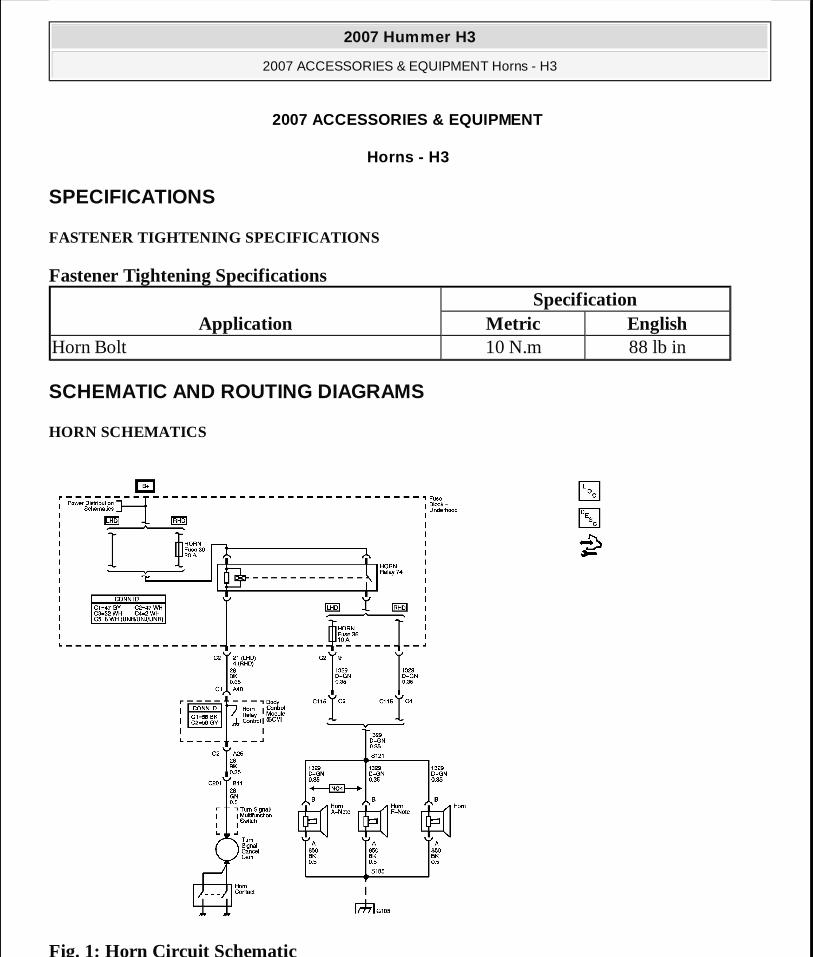
Fig. 2: Forward Lamp Harness Components Courtesy of GENERAL MOTORS CORP.
Callouts For Fig. 2 Callout Component Name
1 S1852 S1093 S1124 S1205 Horn
2007 Hummer H3
2007 ACCESSORIES & EQUIPMENT Horns - H3
MY
Sunday, March 29, 2009 10:22:56 PM Page 2 © 2005 Mitchell Repair Information Company, LLC.
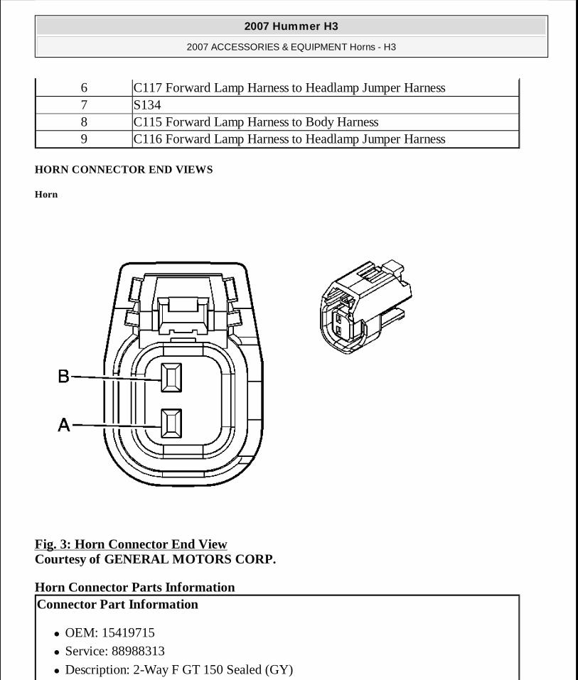
HORN CONNECTOR END VIEWS
Horn
Fig. 3: Horn Connector End View Courtesy of GENERAL MOTORS CORP.
Horn Connector Parts Information
6 C117 Forward Lamp Harness to Headlamp Jumper Harness7 S1348 C115 Forward Lamp Harness to Body Harness9 C116 Forward Lamp Harness to Headlamp Jumper Harness
Connector Part Information
� OEM: 15419715 � Service: 88988313 � Description: 2-Way F GT 150 Sealed (GY)
2007 Hummer H3
2007 ACCESSORIES & EQUIPMENT Horns - H3
MY
Sunday, March 29, 2009 10:22:56 PM Page 3 © 2005 Mitchell Repair Information Company, LLC.

Horn Connector Terminal Identification
Horn A - Note (NO4)
Fig. 4: Horn Connector End View Courtesy of GENERAL MOTORS CORP.
Horn Connector Parts Information
Terminal Part Information
� Terminal/Tray: 12191818/8 � Core/Insulation Crimp: See Terminal Kit � Release Tool/Test Probe: See Terminal Kit
Pin Wire Color Circuit No. FunctionA BK 850 GroundB D-GN 1329 Horn Supply Voltage
Connector Part Information
2007 Hummer H3
2007 ACCESSORIES & EQUIPMENT Horns - H3
MY
Sunday, March 29, 2009 10:22:56 PM Page 4 © 2005 Mitchell Repair Information Company, LLC.
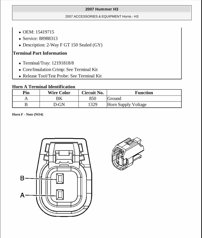
Horn A Terminal Identification
Horn F - Note (NO4)
� OEM: 15419715 � Service: 88988313 � Description: 2-Way F GT 150 Sealed (GY)
Terminal Part Information
� Terminal/Tray: 12191818/8 � Core/Insulation Crimp: See Terminal Kit � Release Tool/Test Probe: See Terminal Kit
Pin Wire Color Circuit No. FunctionA BK 850 GroundB D-GN 1329 Horn Supply Voltage
2007 Hummer H3
2007 ACCESSORIES & EQUIPMENT Horns - H3
MY
Sunday, March 29, 2009 10:22:56 PM Page 5 © 2005 Mitchell Repair Information Company, LLC.
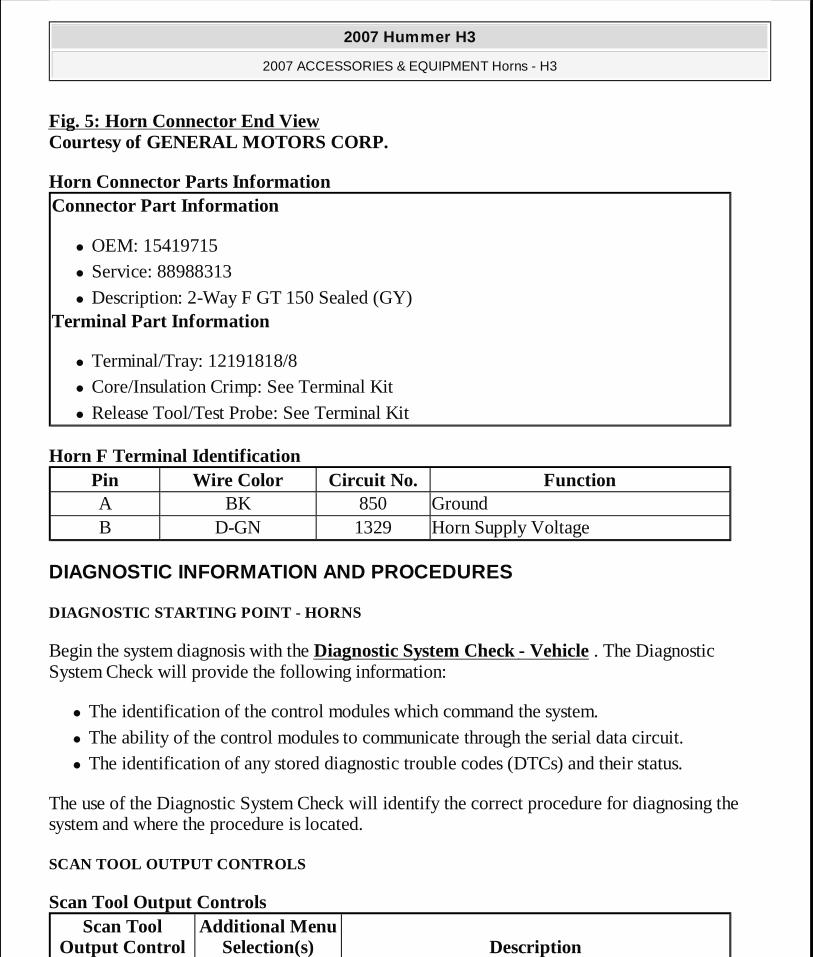
Fig. 5: Horn Connector End View Courtesy of GENERAL MOTORS CORP.
Horn Connector Parts Information
Horn F Terminal Identification
DIAGNOSTIC INFORMATION AND PROCEDURES
DIAGNOSTIC STARTING POINT - HORNS
Begin the system diagnosis with the Diagnostic System Check - Vehicle . The Diagnostic System Check will provide the following information:
� The identification of the control modules which command the system. � The ability of the control modules to communicate through the serial data circuit. � The identification of any stored diagnostic trouble codes (DTCs) and their status.
The use of the Diagnostic System Check will identify the correct procedure for diagnosing the system and where the procedure is located.
SCAN TOOL OUTPUT CONTROLS
Scan Tool Output Controls
Connector Part Information
� OEM: 15419715 � Service: 88988313 � Description: 2-Way F GT 150 Sealed (GY)
Terminal Part Information
� Terminal/Tray: 12191818/8 � Core/Insulation Crimp: See Terminal Kit � Release Tool/Test Probe: See Terminal Kit
Pin Wire Color Circuit No. FunctionA BK 850 GroundB D-GN 1329 Horn Supply Voltage
Scan Tool Output Control
Additional Menu Selection(s) Description
2007 Hummer H3
2007 ACCESSORIES & EQUIPMENT Horns - H3
MY
Sunday, March 29, 2009 10:22:56 PM Page 6 © 2005 Mitchell Repair Information Company, LLC.
SCAN TOOL DATA LIST
The Horns Scan Tool Data List contains all of the horn related parameters that are available on the scan tool. The parameters in the list are arranged in alphabetical order. The column, "Data List," indicates the location of the parameter within the scan tool menu selections. Use the Horns Scan Tool Data List as directed by a diagnostic table or in order to supplement the diagnostic procedures. Begin all of the diagnostic procedures with Diagnostic System Check - Vehicle .
Use the Scan Tool Data List only after the following is determined:
� There is no published DTC procedure nor published symptom procedure for the customer concern.
� The DTC or symptom diagnostic procedure indicated by the diagnostic system check does not resolve the customer concern.
The Typical Data Values are obtained from a properly operating vehicle under the conditions specified in the first row of the Scan Tool Data List table. Comparison of the parameter values from the suspect vehicle with the Typical Data Value(s) may reveal the source of the customer concern.
Scan Tool Data List
SCAN TOOL DATA DEFINITIONS
Battery Voltage
The scan tool displays the current state of the battery in volts.
Horn Relay Command
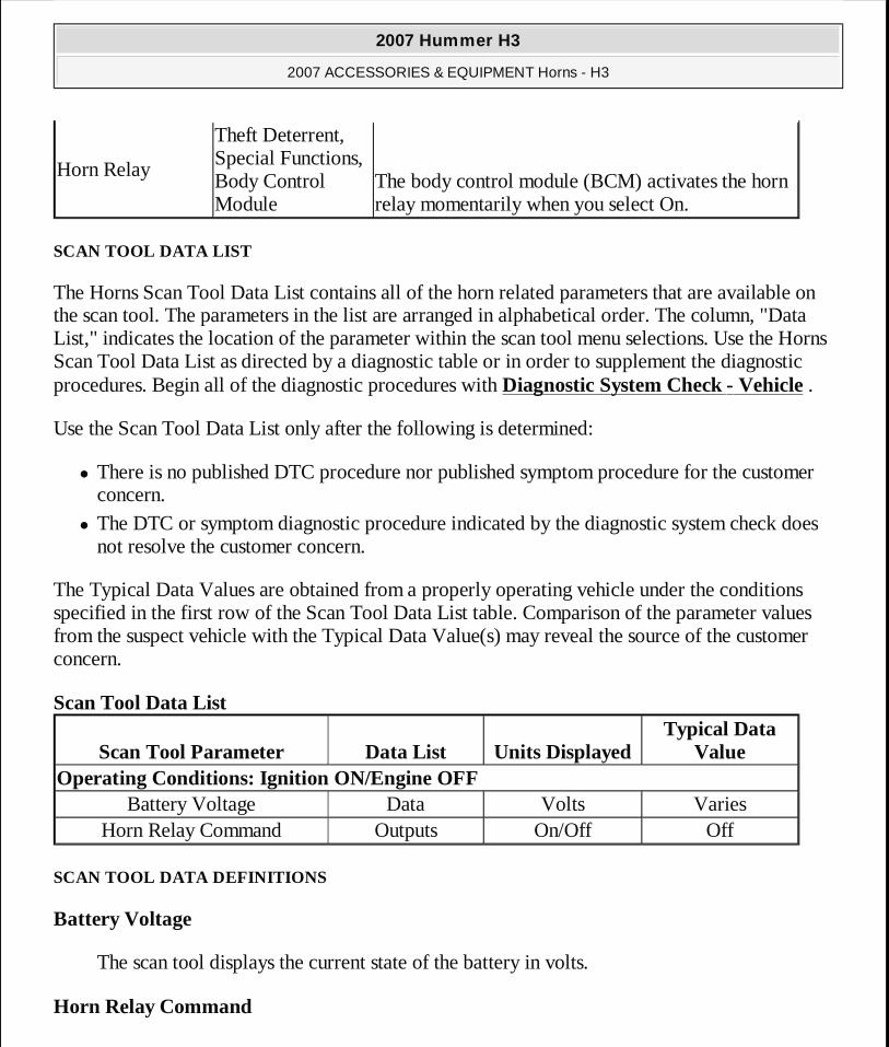
Horn Relay
Theft Deterrent, Special Functions, Body Control Module
The body control module (BCM) activates the horn relay momentarily when you select On.
Scan Tool Parameter Data List Units DisplayedTypical Data
ValueOperating Conditions: Ignition ON/Engine OFF
Battery Voltage Data Volts VariesHorn Relay Command Outputs On/Off Off
2007 Hummer H3
2007 ACCESSORIES & EQUIPMENT Horns - H3
MY
Sunday, March 29, 2009 10:22:56 PM Page 7 © 2005 Mitchell Repair Information Company, LLC.

The scan tool displays On/Off to indicate the current state of the horn relay as commanded by the body control module (BCM) or the horn switch.
SYMPTOMS - HORNS
Review the system operation in order to familiarize yourself with the system functions. Refer to Horns System Description and Operation.
Visual/Physical Inspection
� Inspect for aftermarket devices which could affect the operation of the horn system. Refer to Checking Aftermarket Accessories .
� Inspect the easily accessible or visible system components for obvious damage or conditions which could cause the symptom.
� Perform the following if a horn buzzes or has a harsh tone: � Inspect for debris in the joint where the horn fastens to the vehicle. � Test the torque of the horn mounting hardware. The horn mounting hardware should be
tightened to a torque of 10 N.m (7 lb ft).
Intermittent
Faulty electrical connections or wiring may be the cause of intermittent conditions. Refer to Testing for Intermittent Conditions and Poor Connections .
Symptom List
Refer to a symptom diagnostic procedure from the following list in order to diagnose the symptom:
� Horns Always On
� Horns Inoperative
� Horns - Poor Tone
HORNS ALWAYS ON
Test Description
The number below refers to the step number on the diagnostic table.
IMPORTANT: The following steps must be completed before using the symptom tables:
2007 Hummer H3
2007 ACCESSORIES & EQUIPMENT Horns - H3
MY
Sunday, March 29, 2009 10:22:56 PM Page 8 © 2005 Mitchell Repair Information Company, LLC.
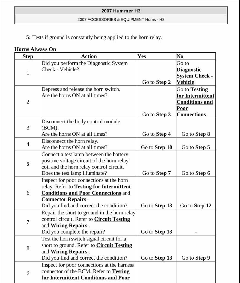
5: Tests if ground is constantly being applied to the horn relay.
Horns Always On Step Action Yes No
1
Did you perform the Diagnostic System Check - Vehicle?
Go to Step 2
Go to Diagnostic System Check - Vehicle
2
Depress and release the horn switch. Are the horns ON at all times?
Go to Step 3
Go to Testing for Intermittent Conditions and Poor Connections
3Disconnect the body control module (BCM). Are the horns ON at all times? Go to Step 4 Go to Step 8
4Disconnect the horn relay. Are the horns ON at all times? Go to Step 10 Go to Step 5
5
Connect a test lamp between the battery positive voltage circuit of the horn relay coil and the horn relay control circuit. Does the test lamp illuminate? Go to Step 7 Go to Step 6
6
Inspect for poor connections at the horn relay. Refer to Testing for Intermittent Conditions and Poor Connections and Connector Repairs . Did you find and correct the condition? Go to Step 13 Go to Step 12
7
Repair the short to ground in the horn relay control circuit. Refer to Circuit Testing and Wiring Repairs . Did you complete the repair? Go to Step 13 -
8
Test the horn switch signal circuit for a short to ground. Refer to Circuit Testing and Wiring Repairs . Did you find and correct the condition? Go to Step 13 Go to Step 9
9
Inspect for poor connections at the harness connector of the BCM. Refer to Testing for Intermittent Conditions and Poor
2007 Hummer H3
2007 ACCESSORIES & EQUIPMENT Horns - H3
MY
Sunday, March 29, 2009 10:22:56 PM Page 9 © 2005 Mitchell Repair Information Company, LLC.
HORNS INOPERATIVE
Test Description
The numbers below refer to the step numbers on the diagnostic table.
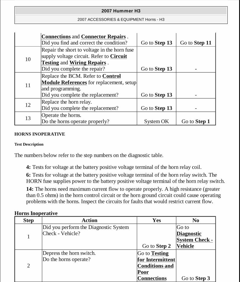
4: Tests for voltage at the battery positive voltage terminal of the horn relay coil.
6: Tests for voltage at the battery positive voltage terminal of the horn relay switch. The HORN fuse supplies power to the battery positive voltage terminal of the horn relay switch.
14: The horns need maximum current flow to operate properly. A high resistance (greater than 0.5 ohms) in the horn control circuit or the horn ground circuit could cause operating problems with the horns. Inspect the circuits for faults that would restrict current flow.
Horns Inoperative
Connections and Connector Repairs . Did you find and correct the condition? Go to Step 13 Go to Step 11
10
Repair the short to voltage in the horn fuse supply voltage circuit. Refer to Circuit Testing and Wiring Repairs . Did you complete the repair? Go to Step 13 -
11
Replace the BCM. Refer to Control Module References for replacement, setup and programming. Did you complete the replacement? Go to Step 13 -
12Replace the horn relay. Did you complete the replacement? Go to Step 13 -
13Operate the horns. Do the horns operate properly? System OK Go to Step 1
Step Action Yes No
1
Did you perform the Diagnostic System Check - Vehicle?
Go to Step 2
Go to Diagnostic System Check - Vehicle
2
Depress the horn switch. Do the horns operate?
Go to Testing for Intermittent Conditions and Poor Connections Go to Step 3
2007 Hummer H3
2007 ACCESSORIES & EQUIPMENT Horns - H3
MY
Sunday, March 29, 2009 10:22:56 PM Page 10 © 2005 Mitchell Repair Information Company, LLC.
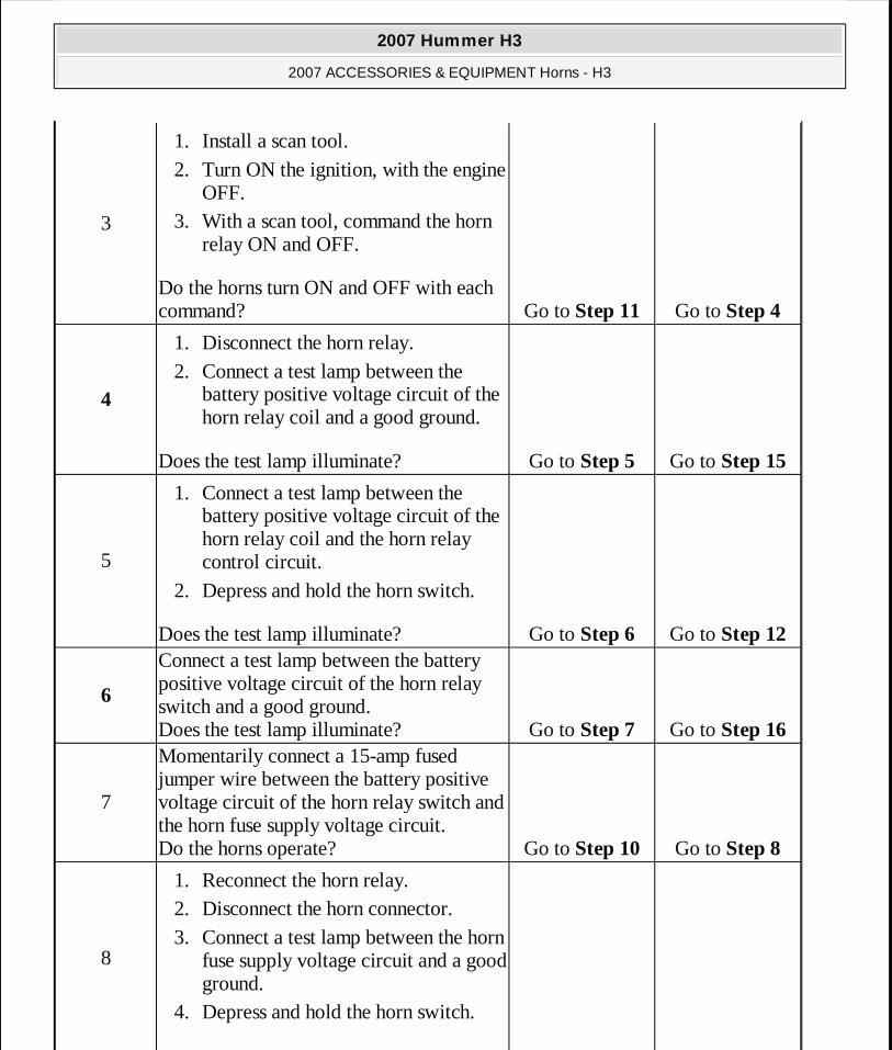
3
1. Install a scan tool. 2. Turn ON the ignition, with the engine
OFF. 3. With a scan tool, command the horn
relay ON and OFF.
Do the horns turn ON and OFF with each command? Go to Step 11 Go to Step 4
4
1. Disconnect the horn relay. 2. Connect a test lamp between the
battery positive voltage circuit of the horn relay coil and a good ground.
Does the test lamp illuminate? Go to Step 5 Go to Step 15
5
1. Connect a test lamp between the battery positive voltage circuit of the horn relay coil and the horn relay control circuit.
2. Depress and hold the horn switch.
Does the test lamp illuminate? Go to Step 6 Go to Step 12
6
Connect a test lamp between the battery positive voltage circuit of the horn relay switch and a good ground. Does the test lamp illuminate? Go to Step 7 Go to Step 16
7
Momentarily connect a 15-amp fused jumper wire between the battery positive voltage circuit of the horn relay switch and the horn fuse supply voltage circuit. Do the horns operate? Go to Step 10 Go to Step 8
8
1. Reconnect the horn relay. 2. Disconnect the horn connector. 3. Connect a test lamp between the horn
fuse supply voltage circuit and a good ground.
4. Depress and hold the horn switch.
2007 Hummer H3
2007 ACCESSORIES & EQUIPMENT Horns - H3
MY
Sunday, March 29, 2009 10:22:56 PM Page 11 © 2005 Mitchell Repair Information Company, LLC.
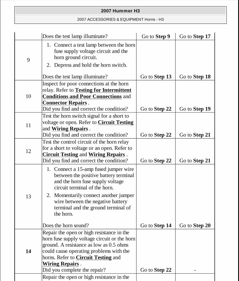
Does the test lamp illuminate? Go to Step 9 Go to Step 17
9
1. Connect a test lamp between the horn fuse supply voltage circuit and the horn ground circuit.
2. Depress and hold the horn switch.
Does the test lamp illuminate? Go to Step 13 Go to Step 18
10
Inspect for poor connections at the horn relay. Refer to Testing for Intermittent Conditions and Poor Connections and Connector Repairs . Did you find and correct the condition? Go to Step 22 Go to Step 19
11
Test the horn switch signal for a short to voltage or open. Refer to Circuit Testing and Wiring Repairs . Did you find and correct the condition? Go to Step 22 Go to Step 21
12
Test the control circuit of the horn relay for a short to voltage or an open. Refer to Circuit Testing and Wiring Repairs . Did you find and correct the condition? Go to Step 22 Go to Step 21
13
1. Connect a 15-amp fused jumper wire between the positive battery terminal and the horn fuse supply voltage circuit terminal of the horn.
2. Momentarily connect another jumper wire between the negative battery terminal and the ground terminal of the horn.
Does the horn sound? Go to Step 14 Go to Step 20
14
Repair the open or high resistance in the horn fuse supply voltage circuit or the horn ground. A resistance as low as 0.5 ohms could cause operating problems with the horns. Refer to Circuit Testing and Wiring Repairs . Did you complete the repair? Go to Step 22 -Repair the open or high resistance in the
2007 Hummer H3
2007 ACCESSORIES & EQUIPMENT Horns - H3
MY
Sunday, March 29, 2009 10:22:56 PM Page 12 © 2005 Mitchell Repair Information Company, LLC.
HORNS - POOR TONE
Horns - Poor Tone
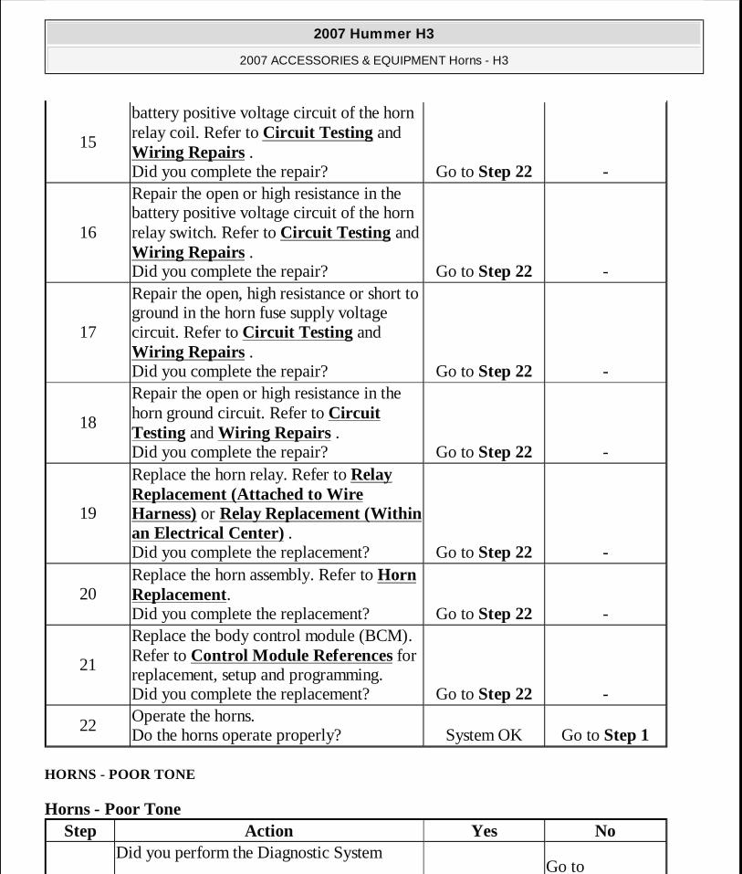
15
battery positive voltage circuit of the horn relay coil. Refer to Circuit Testing and Wiring Repairs . Did you complete the repair? Go to Step 22 -
16
Repair the open or high resistance in the battery positive voltage circuit of the horn relay switch. Refer to Circuit Testing and Wiring Repairs . Did you complete the repair? Go to Step 22 -
17
Repair the open, high resistance or short to ground in the horn fuse supply voltage circuit. Refer to Circuit Testing and Wiring Repairs . Did you complete the repair? Go to Step 22 -
18
Repair the open or high resistance in the horn ground circuit. Refer to Circuit Testing and Wiring Repairs . Did you complete the repair? Go to Step 22 -
19
Replace the horn relay. Refer to Relay Replacement (Attached to Wire Harness) or Relay Replacement (Within an Electrical Center) . Did you complete the replacement? Go to Step 22 -
20Replace the horn assembly. Refer to Horn Replacement. Did you complete the replacement? Go to Step 22 -
21
Replace the body control module (BCM). Refer to Control Module References for replacement, setup and programming. Did you complete the replacement? Go to Step 22 -
22Operate the horns. Do the horns operate properly? System OK Go to Step 1
Step Action Yes NoDid you perform the Diagnostic System
Go to
2007 Hummer H3
2007 ACCESSORIES & EQUIPMENT Horns - H3
MY
Sunday, March 29, 2009 10:22:56 PM Page 13 © 2005 Mitchell Repair Information Company, LLC.

1Check - Vehicle?
Go to Step 2
Diagnostic System Check - Vehicle
2
Depress the horn switch. Do the horns have a harsh tone or buzzing?
Go to Step 3
Go to Testing for Intermittent Conditions and Poor Connections
3
1. Test the horn mounting hardware for adequate torque. Refer to Fastener Tightening Specifications.
2. Inspect the horns for debris in the joint where the horns attach to the vehicle.
Did you find and correct the condition? Go to Step 7 Go to Step 4
4
Perform the following for each of the horns:
1. Disconnect the horn connector. 2. Connect a 15-amp fuse jumper wire
between the positive battery terminal and the horn fuse supply voltage circuit terminal of the horn.
3. Connect another jumper wire between the negative battery terminal and the ground terminal of the horn.
Does the horn have a harsh tone or buzzing?Go to Step 6 Go to Step 5
5
Repair the high resistance in the horn fuse supply voltage circuit or the horn ground circuit. Refer to Circuit Testing and Wiring Repairs . Did you complete the repair? Go to Step 7 -
6Replace the horn. Refer to Horn Replacement. Did you complete the replacement? Go to Step 7 -
7Operate the horns. Do the horns operate properly? System OK Go to Step 1
2007 Hummer H3
2007 ACCESSORIES & EQUIPMENT Horns - H3
MY
Sunday, March 29, 2009 10:22:56 PM Page 14 © 2005 Mitchell Repair Information Company, LLC.
REPAIR INSTRUCTIONS
HORN REPLACEMENT
Removal Procedure
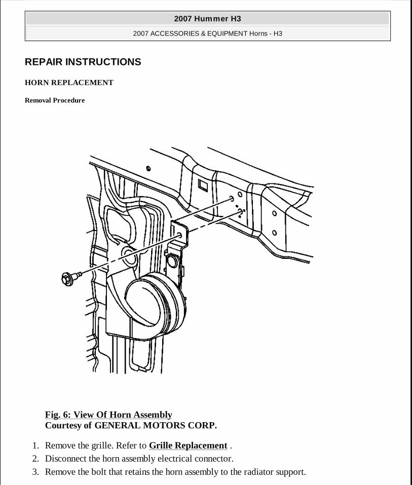
Fig. 6: View Of Horn Assembly Courtesy of GENERAL MOTORS CORP.
1. Remove the grille. Refer to Grille Replacement . 2. Disconnect the horn assembly electrical connector. 3. Remove the bolt that retains the horn assembly to the radiator support.
2007 Hummer H3
2007 ACCESSORIES & EQUIPMENT Horns - H3
MY
Sunday, March 29, 2009 10:22:56 PM Page 15 © 2005 Mitchell Repair Information Company, LLC.

4. Remove the horn assembly from the body.
Installation Procedure
Fig. 7: View Of Horn Assembly Courtesy of GENERAL MOTORS CORP.
1. Install the horn assembly to the radiator support.
2. Install the bolt that retains the horn assembly to the radiator support.
NOTE: Refer to FASTENER NOTICE .
2007 Hummer H3
2007 ACCESSORIES & EQUIPMENT Horns - H3
MY
Sunday, March 29, 2009 10:22:56 PM Page 16 © 2005 Mitchell Repair Information Company, LLC.

Tighten: Tighten the bolt to 10 N.m (88 lb in).
3. Connect the horn assembly electrical connector.
4. Install the grille. Refer to Grille Replacement .
HORN SWITCH REPLACEMENT
The horn switch is an internal component of the steering wheel inflator module and is not serviceable. If the horn switch fails and needs replacement. Refer to Inflatable Restraint Steering Wheel Module Replacement .
DESCRIPTION AND OPERATION
HORNS SYSTEM DESCRIPTION AND OPERATION
System Description
The horn system consists of the following components:
� The HORN fuse � The horn relay � The horn switch � The horn assembly � The body control module (BCM)
System Operation
The vehicle horn system is activated under the following conditions:
� The horn switch is depressed. � The BCM commands the horns on. The BCM commands the horns on under any of the
following conditions: � When the content theft deterrent system detects a vehicle intrusion. For further
information refer to Content Theft Deterrent (CTD) Description and Operation . � When the panic button is depressed on the remote control door lock transmitter. For
further information refer to Keyless Entry System Description and Operation . � When the OnStar® system is used to sound the horns (if equipped.) For further
information refer to OnStar Description and Operation . � When the unlock button on the keyless entry transmitter is pressed, a horn chirp will
2007 Hummer H3
2007 ACCESSORIES & EQUIPMENT Horns - H3
MY
Sunday, March 29, 2009 10:22:56 PM Page 17 © 2005 Mitchell Repair Information Company, LLC.

sound to notify the driver that the vehicle has been unlocked. For further information refer to Keyless Entry System Description and Operation .
� When the lock button on the keyless entry transmitter is pressed twice within 5 seconds, a horn chirp will sound to notify the driver that the vehicle has been locked. For further information refer to Keyless Entry System Description and Operation .
Circuit Operation
Battery positive voltage is applied at all times to the horn relay coil and the horn relay switch. Pressing the horn switch applies ground to the horn relay control circuit. The BCM may also apply ground to the horn relay control circuit as described above. When the horn relay control circuit is grounded, the horn relay is energized and battery positive voltage is applied to the horns through the horn fuse supply voltage circuit. The horns sound as long as ground is applied to the horn relay control circuit.
2007 Hummer H3
2007 ACCESSORIES & EQUIPMENT Horns - H3
MY
Sunday, March 29, 2009 10:22:56 PM Page 18 © 2005 Mitchell Repair Information Company, LLC.