Embed Size (px)
Citation preview
Ref: CG-WI-4.2.4 Ver. 1.0
Page 1 of 42 Date of issue: June 2013
Spec. No.RDSO/2013/CG-05
Signature
Name & Designation
Prepared By
Checked By
Approved By
INDIAN RAILWAYS
SCHEDULE OF TECHNICAL REQUIREMENT
FOR SUPPLY, INSTALLATION, COMMISSIONING & MAINTENANCE OF LED DESTINATION BOARD DISPLAY WITH COACH
DIAGNOSTIC AND INFORMATION SYSTEM FOR IR BG COACHES
S.No. Month/Year of issue
Revision / Amendment Page No. Reason for Amendment
1. October 2013 Nil N A First Issue
Issued By: Carriage Directorate
Research Designs and Standards Organization Manak Nagar, Lucknow - 226011.
DRAFT
Ref: CGW 0001 (Rev. – 3)
Page 2 of 42 Date of issue: June 2013
Spec. No. RDSO/2013/CG-05
Signature
Name & Designation
Prepared By
Checked By
Approved By
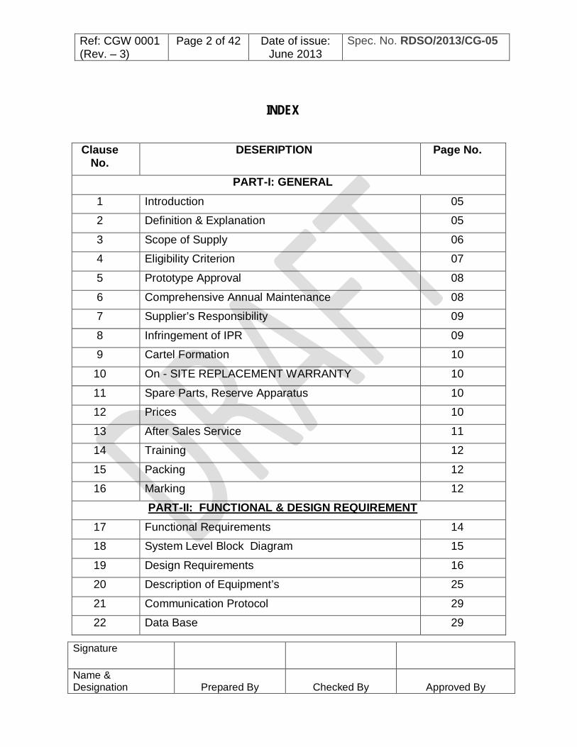
INDEX
Clause No.
DESERIPTION Page No.
PART-I: GENERAL 1 Introduction 05
2 Definition & Explanation 05
3 Scope of Supply 06
4 Eligibility Criterion 07
5 Prototype Approval 08
6 Comprehensive Annual Maintenance 08
7 Supplier’s Responsibility 09
8 Infringement of IPR 09
9 Cartel Formation 10
10 On - SITE REPLACEMENT WARRANTY 10
11 Spare Parts, Reserve Apparatus 10
12 Prices 10
13 After Sales Service 11
14 Training 12
15 Packing 12
16 Marking 12
PART-II: FUNCTIONAL & DESIGN REQUIREMENT
17 Functional Requirements 14
18 System Level Block Diagram 15
19 Design Requirements 16
20 Description of Equipment’s 25
21 Communication Protocol 29
22 Data Base 29

Ref: CGW 0001 (Rev. – 3)
Page 3 of 42 Date of issue: June 2013
Spec. No. RDSO/2013/CG-05
Signature
Name & Designation
Prepared By
Checked By
Approved By
23 Inspection & Tests by Manufacturer/Supplier 30
24 Batch Testing of LEDs. 30
25 Routine tests 30
26 Inspection of Finished Products by Inspecting Authority.
31
Part-III. Infrastructure Requirement 1. Scope 33
2. Requirements 33
3. Manufacturing Facilities 33
4. Testing facilities 34
5. Quality Control Requirements 34
6. Documentation 35
7. Training 35
Annexure No.
Annexure
Description
Annexure-I Location for Fixing/Mounting of LED Destination Board 36
Annexure-II Drawings for Power Supply Connections 37
Annexure-III Parameters to be checked during field Trial. 41
Annexure-IV Undertaking Against Cartel Formation 42

Ref: CGW 0001 (Rev. – 3)
Page 4 of 42 Date of issue: June 2013
Spec. No. RDSO/2013/CG-05
Signature
Name & Designation
Prepared By
Checked By
Approved By
SCHEDULE OF TECHNICAL REQUIREMENTS FOR SUPPLY, INSTALLATION, COMMISSIONING & MAINTENANCE OF LED
DESTINATION BOARD DISPLAY WITH COACH DIAGNOSTIC AND INFORMATION SYSTEM FORIR BG COACHES
Foreword:
0.1 This schedule covers the technical requirements/provision relating to material, tests and does not include all the necessary provisions of contract.
0.2 Specification has been prepared in three parts. Part-I covers the ‘General Requirements, Part-II covers Functional & Requirements and Part-III covers the Infrastructural & Quality Control Requirements for the “SUPPLY, INSTALLATION, COMMISSIONING & MAINTENANCE OF LED DESTINATION BOARD DISPLAY WITH Provision of integration of COACH DIAGNOSTIC AND INFORMATION SYSTEM for IR BG coaches.
0.3 This schedule draws reference of some specifications & drawings. The latest versions of the relevant specifications shall be taken as reference.
0.4 This specification requires the reference to the following specifications: Specification Description RDSO/SPN/144 The Safety and reliability requirement of electronic
signaling equipment.
IS: 9000 Basic environmental testing procedures for electronic and electrical items.
IEC: 60571 Electronic equipment’s used on railway vehicles
IS: 60947-1 IP65 protection 0.5 For the purpose of this specification, the terminology given in RDSO/SPN/144
shall apply. 0.6 In this schedule due consideration has been given to the development in the field
of “Information Technology” process, serviceability, requirement of IR and the practices followed in advanced countries in this field.
0.7 SCOPE: This specification for LED DESTINATION BOARD DISPLAY SYSTEM WITH PROVISION OF INTEGRATION OF COACH DIAGNOSTIC AND INFORMATION SYSTEM for IR coaches covers three parts. Part-I covers general requirements regarding supply, installation, commissioning and after sales service while Part-II covers the functional & Design requirements and method of quality control of the system. Part –III covers the Minimum M&P and Test Equipment’s for the manufacturing and testing of the system.
Ref: CGW 0001 (Rev. – 3)
Page 5 of 42 Date of issue: June 2013
Spec. No. RDSO/2013/CG-05
Signature
Name & Designation
Prepared By
Checked By
Approved By
PART-I: GENERAL REQUIREMENTS
SCHEDULE OF TECHNICAL REQUIREMENT FOR SUPPLY INSTALLATION, COMMISSIONING AND MAINTENANCE OF LED
DESTINATION BOARD DISPLAY WITH COACH DIAGNOSTIC AND INFORMATION SYSTEM FOR IR BG COACHES
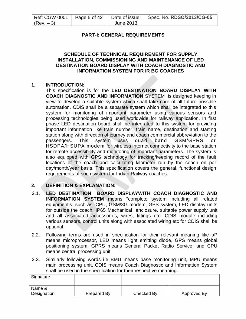
1. INTRODUCTION:
This specification is for the LED DESTINATION BOARD DISPLAY WITH COACH DIAGNOSTIC AND INFORMATION SYSTEM is designed keeping in view to develop a suitable system which shall take care of all future possible automation. CDIS shall be a separate system which shall be integrated to this system for monitoring of important parameter using various sensors and processing technologies being used worldwide for railway application. In first phase LED destination board shall be integrated to this system for providing important information like train number, train name, destination and starting station along with direction of journey and coach commercial abbreviation to the passengers. This system uses quad band GSM/GPRS or HSDPA/HSUPA modem for wireless internet connectivity to the base station for remote accessibility and monitoring of important parameters. The system is also equipped with GPS technology for tracking/keeping record of the fault locations of the coach and calculating kilometer run by the coach on per day/month/year basis. This specification covers the general, functional design requirements of such system for Indian Railway coaches.
2. DEFINITION & EXPLANATION: 2.1. LED DESTINATION BOARD DISPLAYWITH COACH DIAGNOSTIC AND
INFORMATION SYSTEM means "complete system including all related equipment’s, such as, CPU, GSM/3G modem, GPS system, LED display units for outside the coach, IP65 Mechanical enclosure, suitable power supply unit and all associated accessories, wires, fittings etc. CDIS module including various sensors, control units along with associated wiring etc for CDIS shall be optional.
2.2. Following terms are used in specification for their relevant meaning like µP means microprocessor, LED means light emitting diode, GPS means global positioning system, GPRS means General Packet Radio Service, and CPU means central processing unit.
2.3. Similarly following words i.e BMU means base monitoring unit, MPU means main processing unit, CDIS means Coach Diagnostic and Information System shall be used in the specification for their respective meaning.

Ref: CGW 0001 (Rev. – 3)
Page 6 of 42 Date of issue: June 2013
Spec. No. RDSO/2013/CG-05
Signature
Name & Designation
Prepared By
Checked By
Approved By
2.4. `Supplier' means the firm/company on whom the order for the manufacture & supply of the LED DESTINATION BOARD DISPLAY WITH COACH DIAGNOSTIC AND INFORMATION SYSTEM is placed or will be placed.
2.5. ‘PURCHASER’ means the Indian Railways on behalf of the President of the Republic of India who is purchasing the LED destination board display system.
2.6. ‘INSPECTING AUTHORITY’ means the Organisation or its representative nominated by the Purchaser to inspect the destination board display system on his behalf.
2.7. The Research Designs and Standards Organization, Manak Nagar, Lucknow-226011 is here after referred to as RDSO.
2.8. Indian Railways is hereafter referred to as I.R. 2.9. In case of any clarification in respect of any clause of this specification or
drawings, the same shall be obtained from purchaser/DG(Carriage),RDSO. 3. SCOPEOFSUPPLY:
The scope of supply includes the following subsystems:
3.1 Each Coach shall be equipped with following separate units along with required connectors and wiring for communication & power supply as per wiring scheme attached at Annexure 2.
a) Main Processing Unit: one unit per coach Description of Main Processing Unit shall be as per clause no. 20.1 of Part –II of this specification.
b) Coach Diagnostic and Processing Module(Optional ): one unit per coach
Description of Coach DIAGNOSTIC and processing module shall be as per clause no. 20.2 of Part –II of this specification.
c) Slave Destination Board Display system: Two units per coach
Description of Slave Destination Board Display system shall be as per clause no. 20.3 of Part –II of this specification.
d) Boxed enclosure Power Supply unit : one unit per coach
Description of Boxed enclosure Power Supply unit shall be as per clause no. 20.4 of Part –II of this specification.

Ref: CGW 0001 (Rev. – 3)
Page 7 of 42 Date of issue: June 2013
Spec. No. RDSO/2013/CG-05
Signature
Name & Designation
Prepared By
Checked By
Approved By
e) Cable junction box: one unit per coach Cable junction box for all the signals or power supply wires coming to CDIS unit or Main processing unit shall be suitably labeled, numbered for easy identification and maintainability.
All the units Except Slave destination board may be mounted in a NEMA standard enclosure unit and this integrated unit shall be mounted at suitable location in the coach power panel or any other suitable place. At least 2 USB interfaces of Main Processing unit, LCD touch screen, SIM slots for GSM / 3G modem, on/off switch, power indicator shall be provided in front side of the enclosure unit for easy accessibility. Enclosure unit shall be designed with anti-pilferage features with provision of special lock and key.
3.2 Base Monitoring Unit - Two units at each Depot
Description of Base Monitoring Unit shall be as per clause no. 20.5 of Part –II of this specification.
3.3 Centralized Web Server (not in the scope of supply): For hosting of online services and database of all the train routes, rake
formations of trains a web server ( server availability 99.9 % uptime round the clock ) shall be hired by Indian Railway to serve the entire fleet of coaches as well as prospectus users (Indian Railway and system supplier users) of the system.
3.4 The scope of the supply includes acceptance testing, installation and commissioning of the complete system on the coaches, On-Site Replacement Warranty for two year and commitment to undertake Comprehensive Annual Maintenance Contract after warranty period.
3.5 Scope of supply includes PC software (Operating System and client software for web application) for preparation of train routes, rake formation and editing the same, uploading and downloading of route data and other information.
3.6 The purchaser can purchase any or all of the above sub systems based on their requirements.
4. ELIGIBILITY CRITERIA:
4.1 Firm /manufacturer shall have adequate experience of design, development and manufacturing of similar system like onboard vehicle tracking, monitoring of assets, passenger information display boards or online management of data interchange between control center system and onboard system in rolling stock (rail / road transport) application and shall be capable of developing material to the required quality and standards.

Ref: CGW 0001 (Rev. – 3)
Page 8 of 42 Date of issue: June 2013
Spec. No. RDSO/2013/CG-05
Signature
Name & Designation
Prepared By
Checked By
Approved By
4.2 Firm/ manufacturer should have installed successfully at least 100 such systems in past and have completed minimum two years satisfactory service. The list of supplies made along with contact details of the customers and performance certificate should be submitted as documentary evidence.
5. PROTOTYPE APPROVAL AND FIELD TRIAL PERFORMANCE MONITORING:
5.1 The prototype approval by RDSO shall be mandatory in all cases including any design change / new vendor followed by field trial performance monitoring of the system offered free of cost and same has been allowed for field trial by RDSO in any Railway. Parameters for the performance field trial are specified at Annexure ‘3’.
5.2 For field trial performance monitoring of the system, newly approved firm can participate in tenders of any railway. Such firm shall initially supply (if eligible in tender process) only 10 coach sets to any one railway for field trial of 3 months and balance quantity shall be accepted only after successful field trial. Concerned Railway should satisfy himself the requirement of successful field trial of 3 months on 10 coach sets (if not done), before giving partial or full orders to the firms.
6. COMPREHENSIVE ANNUAL MAINTENANCE CONTRACT: The SUPPLIER shall be liable for Comprehensive Annual Maintenance Contract. Comprehensive annual maintenance shall be required for the ‘LED DESTINATION BOARD DISPLAYWITH COACH DIAGNOSTIC AND INFORMATION SYSTEM’ for maintaining the system. The Comprehensive annual maintenance shall include the following items:
A) TRIP Maintenance: a. Checking the entire system for its:
Working and reliability. Mechanical fixing thoroughly.
b. Checking the entire system for water-tight sealing arrangement and any visual defect.
c. Monitoring the power supply, voltage, and wiring etc. periodically.
B) Three monthly Maintenance: a. Monitoring the antenna connectors. b. The maintenance shall cover the free replacement of entire
components including MODEM, CPU, SMPS, ANTENNA etc. if found faulty/ defective.

Ref: CGW 0001 (Rev. – 3)
Page 9 of 42 Date of issue: June 2013
Spec. No. RDSO/2013/CG-05
Signature
Name & Designation
Prepared By
Checked By
Approved By
Note: 1. Any fault / defect shall be rectified within period as agreed between supplier
and purchaser. 2. The maintenance shall also cover the updating of route data / customized
messages in all coach units installed as per latest time table of I.R. as and when required by the purchaser. After updating route data a soft copy of updated route data shall be submitted to the purchaser.
3. Sup p l i e r shall also update / change the system software as and when required by the purchaser.
4. The railway authorities shall provide necessary arrangements for the checking / fixing of the DISPLAY BOARDS & CDIS and ensure that the checking is carried out under safe conditions.
5. The Supplier shall ensure that the D.C power supply provided to the systems are working properly, if any problem in the Power source the railways shall ensure that the problem is solved.
7. SUPPLIER’S RESPONSIBILITY
7.1 The Supplier shall be responsible for the execution of the contract strictly in accordance with the terms of this specification and the conditions of contract, not withstanding any approval which purchaser or the Inspecting Officer may have given for the following: a) The detailed drawings prepared by the Supplier. b) His Supplier for materials.
7.2 The test carried out either by the Supplier and / or by the purchaser and / or the Inspecting Officer.
8. INFRINGEMENT OF IPR
Undertaking to be signed by Vendors on “INFRINGEMENT OF PATENT RIGHTS”. The undertaking can be as under. “Indian Railways shall not be responsible for infringement of patent rights arising due to similarity in design, manufacturing process, use of similar components in the design & development of this item and any other factor not mentioned herein which may cause such a dispute. The entire responsibility to settle any such disputes/matters lies with the manufacturer/ supplier. Details / design/documents given by them are not infringing any IPR and they are responsible in absolute and full measure instead of railways for any such violations. Data, specifications and other IP as generated out of interaction with railways shall not be unilaterally used without the consent of RDSO and right of Railways / RDSO on such IP is acceptable to them.”
Ref: CGW 0001 (Rev. – 3)
Page 10 of 42
Date of issue: June 2013
Spec. No. RDSO/2013/CG-05
Signature
Name & Designation
Prepared By
Checked By
Approved By
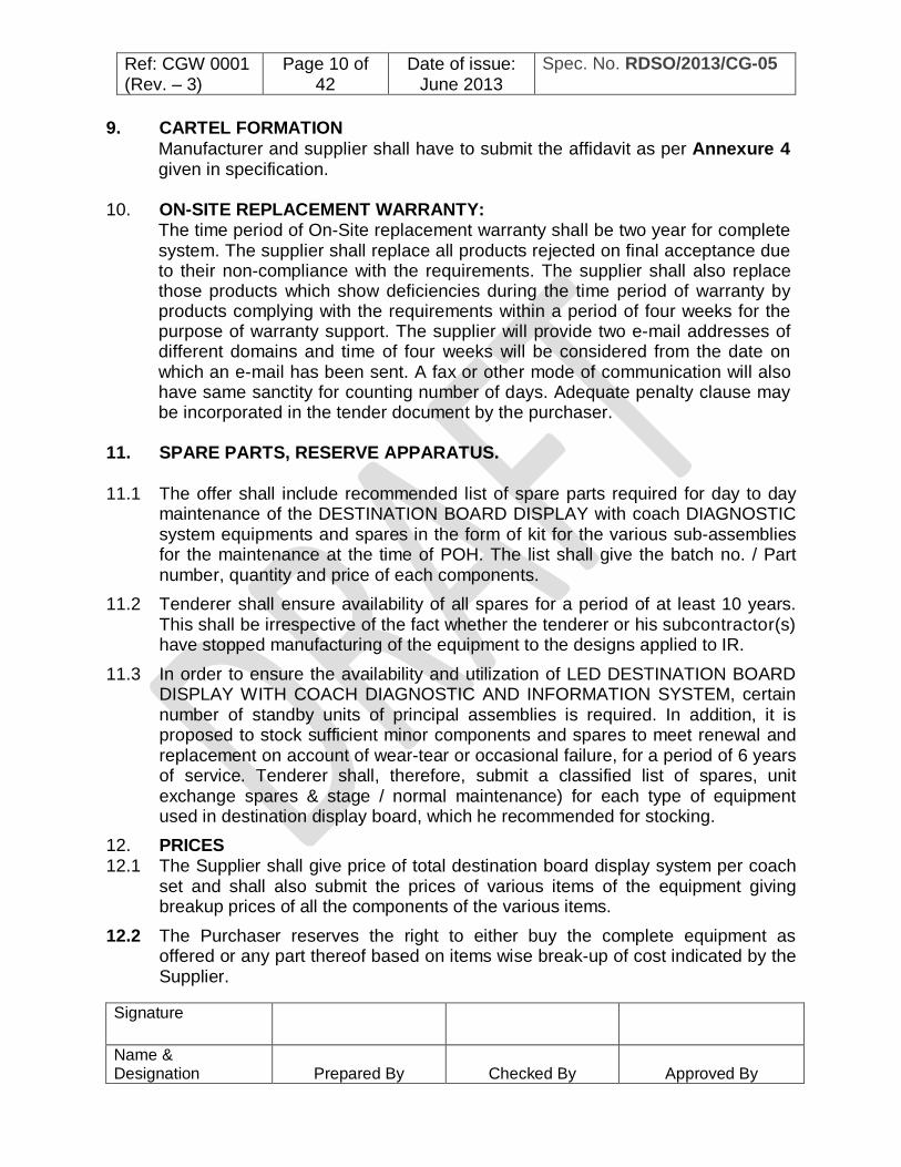
9. CARTEL FORMATION Manufacturer and supplier shall have to submit the affidavit as per Annexure 4 given in specification.
10. ON-SITE REPLACEMENT WARRANTY:
The time period of On-Site replacement warranty shall be two year for complete system. The supplier shall replace all products rejected on final acceptance due to their non-compliance with the requirements. The supplier shall also replace those products which show deficiencies during the time period of warranty by products complying with the requirements within a period of four weeks for the purpose of warranty support. The supplier will provide two e-mail addresses of different domains and time of four weeks will be considered from the date on which an e-mail has been sent. A fax or other mode of communication will also have same sanctity for counting number of days. Adequate penalty clause may be incorporated in the tender document by the purchaser.
11. SPARE PARTS, RESERVE APPARATUS.
11.1 The offer shall include recommended list of spare parts required for day to day maintenance of the DESTINATION BOARD DISPLAY with coach DIAGNOSTIC system equipments and spares in the form of kit for the various sub-assemblies for the maintenance at the time of POH. The list shall give the batch no. / Part number, quantity and price of each components.
11.2 Tenderer shall ensure availability of all spares for a period of at least 10 years. This shall be irrespective of the fact whether the tenderer or his subcontractor(s) have stopped manufacturing of the equipment to the designs applied to IR.
11.3 In order to ensure the availability and utilization of LED DESTINATION BOARD DISPLAY WITH COACH DIAGNOSTIC AND INFORMATION SYSTEM, certain number of standby units of principal assemblies is required. In addition, it is proposed to stock sufficient minor components and spares to meet renewal and replacement on account of wear-tear or occasional failure, for a period of 6 years of service. Tenderer shall, therefore, submit a classified list of spares, unit exchange spares & stage / normal maintenance) for each type of equipment used in destination display board, which he recommended for stocking.
12. PRICES 12.1 The Supplier shall give price of total destination board display system per coach
set and shall also submit the prices of various items of the equipment giving breakup prices of all the components of the various items.
12.2 The Purchaser reserves the right to either buy the complete equipment as offered or any part thereof based on items wise break-up of cost indicated by the Supplier.

Ref: CGW 0001 (Rev. – 3)
Page 11 of 42
Date of issue: June 2013
Spec. No. RDSO/2013/CG-05
Signature
Name & Designation
Prepared By
Checked By
Approved By
13. AFTER SALESSERVICE 13.1 Supplier is required to send his technical staff during the installation and
commissioning of their equipment on coach / coaches. 13.2 Supplier shall arrange for adequate service engineers at his own cost to ensure
that the equipment supplied performs satisfactorily. 13.3 Supplier shall also depute his staff on request by the Purchaser / RDSO, to
investigate and attend to specific problems that may come up during actual operation of destination board display system.
13.4 Supplier shall associate with Indian Railways during the trials of destination board display system. He shall also undertake to modify the equipment supplied, if required as a result of trials.
13.5 The Supplier shall arrange to supply at least 5 hard & soft copies of the Operation & Maintenance Manuals and servicing Instructions for proper maintenance of equipment. The number of manuals to be supplied shall be 5 against first Contract and 2 at every contract and shall be supplied free of cost.
13.6 Manuals shall be illustrated, containing information pertaining to the principle of operation, maintenance schedule of all the items o f equipment being supplied.
13.7 The Manual shall also contain information on the following Details of attention required during IOH / POH or any other schedule.
13.8 Test procedure and standards for various DESTINATION BOARD DISPLAY with CDIS system equipments on test bench as well as single unit / coach /rake testing.
13.9 Details of gauges, jigs &fixture, tools, machinery and plant for maintenance of destination board display system.
13.10 Typical defects and their remedial measures. 13.11 List of spares for day-to-day maintenance and for POH in the form of periodic
overhaul kit. 13.12 Identification codes for main equipment and their component parts to avoid mixing
of different applications by mistake. 13.13 Tenderer shall submit the frequency and detailed work content of various
inspection/maintenance schedule necessary for maintenance of DESTINATION BOARD DISPLAY with CDIS system offered by him. Whether these requirements are time based or distance traveled based shall be indicated for each schedule.
13.14 The Supplier shall also arrange to supply along with equipment Wall Charts of all equipment being supplied by them for display in maintenance depots. These shall be supplied @ 5 sets against first contract and thereafter 2 sets against every contract and shall be supplied free of cost. These charts shall be pictorial, showing all components along with their part Nos. for each item of equipment.
Ref: CGW 0001 (Rev. – 3)
Page 12 of 42
Date of issue: June 2013
Spec. No. RDSO/2013/CG-05
Signature
Name & Designation
Prepared By
Checked By
Approved By
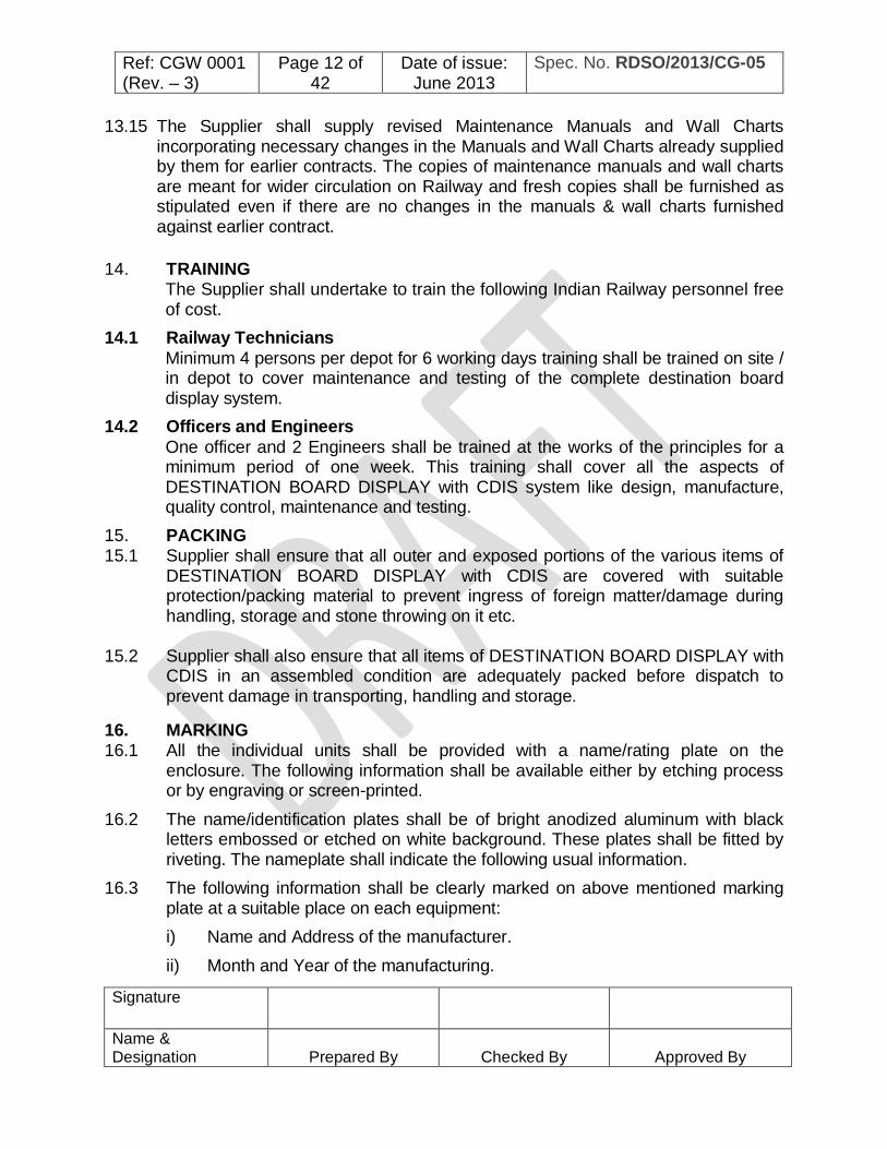
13.15 The Supplier shall supply revised Maintenance Manuals and Wall Charts incorporating necessary changes in the Manuals and Wall Charts already supplied by them for earlier contracts. The copies of maintenance manuals and wall charts are meant for wider circulation on Railway and fresh copies shall be furnished as stipulated even if there are no changes in the manuals & wall charts furnished against earlier contract.
14. TRAINING
The Supplier shall undertake to train the following Indian Railway personnel free of cost.
14.1 Railway Technicians Minimum 4 persons per depot for 6 working days training shall be trained on site / in depot to cover maintenance and testing of the complete destination board display system.
14.2 Officers and Engineers One officer and 2 Engineers shall be trained at the works of the principles for a minimum period of one week. This training shall cover all the aspects of DESTINATION BOARD DISPLAY with CDIS system like design, manufacture, quality control, maintenance and testing.
15. PACKING 15.1 Supplier shall ensure that all outer and exposed portions of the various items of
DESTINATION BOARD DISPLAY with CDIS are covered with suitable protection/packing material to prevent ingress of foreign matter/damage during handling, storage and stone throwing on it etc.
15.2 Supplier shall also ensure that all items of DESTINATION BOARD DISPLAY with
CDIS in an assembled condition are adequately packed before dispatch to prevent damage in transporting, handling and storage.
16. MARKING 16.1 All the individual units shall be provided with a name/rating plate on the
enclosure. The following information shall be available either by etching process or by engraving or screen-printed.
16.2 The name/identification plates shall be of bright anodized aluminum with black letters embossed or etched on white background. These plates shall be fitted by riveting. The nameplate shall indicate the following usual information.
16.3 The following information shall be clearly marked on above mentioned marking plate at a suitable place on each equipment: i) Name and Address of the manufacturer. ii) Month and Year of the manufacturing.
Ref: CGW 0001 (Rev. – 3)
Page 13 of 42
Date of issue: June 2013
Spec. No. RDSO/2013/CG-05
Signature
Name & Designation
Prepared By
Checked By
Approved By
iii) Serial number of Equipment iv) Specification number v) Software and hardware version vi) Schematic diagram of the equipment on the side of the cover.
16.4 The first two digits shall indicate the year of manufacturing and next two digits shall
indicate month. Further next three digits shall indicate manufacturing serial number.
***********************************

Ref: CGW 0001 (Rev. – 3)
Page 14 of 42
Date of issue: June 2013
Spec. No. RDSO/2013/CG-05
Signature
Name & Designation
Prepared By
Checked By
Approved By
17. FUNCTIONAL REQUIREMENTS:
PART II: FUNCTIONAL & DESIGN REQUIREMENTS
17.1 Ambient conditions: The display unit shall perform satisfactorily under the following climatic conditions i) Ambient temperature : -5oC to 55oC ii) Max. Sunlight temperature : 700C ii) Altitude : Sea level to 2500 m iv) Relative humidity : 40% to 98% v) The rainfall is fairly heavy. vi) During dry weather, the atmosphere is likely to be full of dirt & dust. vii) Temperature variation may be quite high in the same journey or short
period of time. viii) Coaches operate in coastal areas with continued exposure to salt laden air. ix) Airborne contaminants like smoke and chemical vapors. x) Conducting particles like metal clips and filings. xi) Accidental short circuit by dropped tools, fasteners etc. xii) Stones may be thrown on the system by the ant-social elements during
procession or strikes etc. xiii) Abrasion damage and xiv) Vibration and shock
17.2 Maintenance Conditions: The coach exteriors are cleaned with mildly acidic cleaning agents using brushes with nonmetallic bristles or automatic car washing plants. The system should not be affected by this cleaning either in performance, reliability or aesthetic.
17.3 Power Supply Availability 110V AC or DC supply is available from coach circuits. This Supply varies from 77V DC to 138 V DC with 2% ripple.
17.4 Car-body dynamics: ±100 mm vertically ±55 mm laterally ±10 mm longitudinally ±4 degree bogie rotation about center pivot

Ref: CGW 0001 (Rev. – 3)
Page 15 of 42
Date of issue: June 2013
Spec. No. RDSO/2013/CG-05
Signature
Name & Designation
Prepared By
Checked By
Approved By
18.
SYSTEM LEVEL BLOCK DIAGRAM
INTERNET
GPRS ANTENNA
GPRS MODEM
COMMON WEB SERVER FOR
ALL SERVICES
SERVICE PROVIDERS
SERVER/ CELL TOWER
N/W
BMU N/W
N/W CELL TOWER
Cell tower N/W
CDIS MODULE
GPRS ANTENNA – coach 1
SLAVE 1, 2 DESTINATION
Main processing unit
CDIS module
GPRS ANTENNA – coach 2
SLAVE 1, 2 destination
Main processing unit
CDIS module
GPRS ANTENNA – coach -n
SLAVE 1,2 destination
Main processing unit
ONE TRAIN RAKE
BASE MONITORING UNIT AT USER
/VENDOR
WEB SERVER CONNECTIVITY VIA INTERNET
WI-FI LAN FOR TRANSFER OF CONFIGURATION FILES
((( WLAN)))
((( WLAN)))
((( WLAN)))
((( WLAN))) GPRS ANTENNA
Ref: CGW 0001 (Rev. – 3)
Page 16 of 42
Date of issue: June 2013
Spec. No. RDSO/2013/CG-05
Signature
Name & Designation
Prepared By
Checked By
Approved By
19. DESIGN REQUIREMENTS: The “GSM/GPRS Controlled LED DESTINATION BOARD DISPLAY WITH COACH DIAGNOSTIC AND INFORMATION SYSTEM”, including all sub-systems and equipment shall be of proven design. Entire system can be understood by “SYSTEM LEVEL BLOCK DIAGRAM” as shown above which elaborates the system working / requirements.
19.1 MAIN PROCESSING UNIT (MPU) shall have following features.
19.1.1 Main processing unit shall consists of built-in GSM /3G modem, GPS
receiver, 5 to 7 inch capacitive touch screen interface along with suitable system software (Windows / Linux embedded), processing memory 1 GB minimum and storage memory 32 GB on board. The system shall also have various serial interface modules like USB, RS485, RS232, the system shall also have wireless LAN / WAN module, IP65 protected mechanical enclosure unit with provision of external antenna for GSM modem and GPS receiver.
19.1.2 The Main Processing unit shall support the Coach Diagnostic and Information System (CDIS) unit. Proposed CDIS unit shall acquire signals from the various devices fitted in the coach like Water Level measurement system, hot bearing monitoring system, Temperature Level Monitoring system etc. All such devices will be connected to CDIS over the available analogue or digital communication channels (full duplex RS485 at 57600bps baud rate, WLAN / Ethernet network etc.). Such signals acquired by the CDIS shall be analyzed/ processed for the generating required final reports/ logs /alerts in form of data /database files only. These data /database files shall be transferred to MPU with standard file transfer /copying / synchronizing techniques, So that these database files can be forwarded using the GSM modem / WLAN network of the Main Processing Unit to a central web server. In case the GSM network is not available, such data shall be queued in Main Processing Unit and forwarded on availability of GSM connectivity. Data so received at the Central Web Server through the MPU shall be forwarded to the specific application servers connected to the Web server system using standard IP based network (not in scope of this specification). In this manner, MPU shall act as a versatile standard communication device for other intelligent devices provided in the coach at present and in future.
19.1.3 Both LED Display Panels shall operate as slave units and consist of LED Matrix Display cards along with LED driver Circuitry and a microprocessor based LED driver Control Module for controlling the LED Display Cards.
19.1.4 The MPU shall be capable of communicating with at least 2 display panels
Ref: CGW 0001 (Rev. – 3)
Page 17 of 42
Date of issue: June 2013
Spec. No. RDSO/2013/CG-05
Signature
Name & Designation
Prepared By
Checked By
Approved By
connected outside the coach over RS485 interface. It shall be possible to add more displays in future.
19.1.5 Each Display Board shall have a Unique Hardware identification number stored within the destination board. Unique HW ID of the DESTINATION DISPLAY BOARD (DDB) shall be a 12-digit code where first three digits shall be vendor code followed by 4 digit of month and year of manufacture (mm/yy format) and the other 5 digits shall be unique serial number assigned by vendor. Vendor code will be assigned after validation of vendor request by RDSO.
19.1.6 Each Main Processing unit shall be identified digitally with an alphanumeric character (up to 12 characters) of the coach number like, "SC 00245" or "NCR 00245". Where first two/three digits are Zonal Railway Code, next two digits are year of manufacture and the last three digits are running serial number of the coach. Using this digital identification it can be ensured that only the target rake or set of coaches receives the command while programming through BMU / Central web server. The Main Processing unit (MPU) shall also have Hardware ID code similar to DDB in the embedded memory which can be retrieved by the user at any point of time through the BMU or Central server.
19.1.7 The MPU of each coach shall be pre-programmed for the Train routes in Hindi, English and Regional languages for the desired locations / stations along with GPS coordinates using BMU / web server. This system shall have capability to handle the data base of at least 100 up and 100 down train routes with up to 4 language support and capability to display all regional languages recognized and listed in the 8th Schedule of the Constitution of India. The display data available in the memory can be replaced to any required new train data by transferring fresh data from the BMU /Central server; (the old data version is overwritten automatically in such a case). Provision of USB Interface shall be made for data transfer at a high speed.
19.1.8 The GSM module of MPU shall be provided with a SIM card with national roaming providing pan-India connectivity. The MPU shall always remain connected with the Web server over GSM/GPRS service. Such status will be updated to the Web Server. The vendor shall provided necessary application Programming interface on the MPU to allow effective communication with web server.
19.1.9 In case connectivity to web server is not available, the service requests shall be queued for updating, whenever connectivity is available it shall be updated automatically. it shall be possible for a remote user on a internet enabled PC (BMU) to view the state of a configuration service request and whether the same has been acknowledged or not.

Ref: CGW 0001 (Rev. – 3)
Page 18 of 42
Date of issue: June 2013
Spec. No. RDSO/2013/CG-05
Signature
Name & Designation
Prepared By
Checked By
Approved By
19.1.10 When the train passes through programmed train route, GPS receiver receives co-ordinates information of the current location from the GPS satellites. Upon arrival at the destination station, the MPU shall automatically reset the selected train number and send a request for new configuration to the server or load follow-up route already selected at server side.
19.1.11 When the Main Processing unit is changed/ replaced from one coach to the other, It shall be possible to modify the coach-id stored in the MPU either through the GSM interface (online mode) or manually by touch screen interface provided in MPU, However such modification shall be authenticated password protected. Once updating is done, the coach ID configured on the MPU can be visually verified on the LCD screen of the MPU .
19.1.12 It should be possible to upgrade/ extend the system. There shall be provision to add extra display units without any change in electronics.
19.1.13 Each trains entire route shall be pre-programmed for the desired locations/
stations & regional languages with 4 languages support of each train route. All such routes shall be synchronized with web server for the latest version. If any new route is desired to be programmed web server shall replace the lowest used record of train route on date stamp basis.
19.1.14 Train route selection on Main Processing Unit shall be done using web server interface normally; in case of failure of this mode other options like SMS, configuration file transfer through WLAN or touch screen interface available in the system shall be used for selection of train route.
19.1.15 MPU shall be capable of sending information / recorded messages/ logs / alerts generated on receiving the request from Base monitoring unit / web server as and when required.
19.1.16 The system shall work primarily in the online mode whereby a user can upload /download Train route information to the MPU over the GSM/GPRS network. GSM module on the MPU shall communicate with the Online web server for getting the information. As a standby, it shall be possible to update the train route information using a USB pen-drive also.
19.1.17 The user shall be able to configure the desired rake composition assigning requisite coaches and select train number for the complete rake over GSM network using a BMU. Software application on the server side shall ensure scheduled and unscheduled mid-route removal and addition of coaches to a particular rake/ train. If it is desired to configure any specific train route to a particular coach/set of coach it shall also be done normally over GSM interface, but it shall be possible to manually configure the MPU with the help of a touch screen keypad in the system, such selection shall be password protected.

Ref: CGW 0001 (Rev. – 3)
Page 19 of 42
Date of issue: June 2013
Spec. No. RDSO/2013/CG-05
Signature
Name & Designation
Prepared By
Checked By
Approved By
19.1.18 In case of failure of GSM communication or non-availability of Internet Enabled PC (BMU) at site, the user shall be able to compile the information using BMU application software in offline mode and upload the ad-hoc information to the MPU using a USB pen drive or Portable Hard Disk Drive such updating shall be authenticated password protected.
19.1.19 Any ad-hoc data upload/download and configuration of the MPU shall be logged with a date and time stamp and shall be downloaded to the server system upon availability of network.
19.1.20 The MPU shall have on-board diagnostics for working status of GPS module, GPS antenna status, on-board memory, connectivity with the slave systems, working status of the Slave Destination Board working status of all the devices connected to the CDIS etc. and update the status on the server upon availability of network connectivity.
19.1.21 In case a fault is detected, the MPU shall be capable of storing such faults with date and time stamp, Provision for storing up to 200 such most recent faults on FIFO basis shall be provided in MPU. Faults shall be retrievable either by the online fault retrieval system for generation of reports or through the USB interface of the MPU manually using a standard pen drive. In case of manual retrieval existing faults shall not be reset from memory.
19.1.22 Kilometer-age earned by each coach shall be computed & logged date-wise data of kilometer run for the last 36 months on the basis of GPS information by MPU to assist in creating maintenance schedules.
19.1.23 Distance travelled shall be computed based on location data stored in train routes. . Distance travelled log shall be prepared based on the available GPS accuracy and cumulative kilometrage earned date wise shall be stored in the MPU and same shall be synchronised to the web server at regular interval. This information shall be accessible through a BMU for review by the POH staff to assist in the maintenance activity. Kilometers earned shall also be retrievable using the USB interface of the MPU and can be seen on MPU LCD also whenever it is required.
19.2 Base Monitoring Unit shall have following Design features: Base Monitoring Unit (BMU) is a standard workstation Personal Computer, which shall work on latest windows® software. The BMU shall be connected to GSM/3G data Modem, and also with wired broad band internet with fixed IP address for the connectivity with the web server.

Ref: CGW 0001 (Rev. – 3)
Page 20 of 42
Date of issue: June 2013
Spec. No. RDSO/2013/CG-05
Signature
Name & Designation
Prepared By
Checked By
Approved By
BLOCK DIAGRAM OF BASE MONITORING UNIT (BMU)
(FOR USER RAILWAY)
Normally following tasks shall be done by Base Monitoring Unit: 19.2.1 Train rake composition data shall be entered at originating station by TXR
staff using this Base Monitoring Unit via web server. Using rake composition data it shall be possible to select the train route for entire rake in one command.
19.2.2 Retrieval recorded messages / alerts / logs/ reports generated of coach health from Main Processing Unit and compilation of final reports for the maintenance staff.
19.2.3 Provision of wireless LAN communication for data upload / retrieval within effective range of network signal strength at specified division /depots. WLAN should follow defined communication protocol IEEE 802.11a/b/g/n for data throughput and effective range of communication.
19.2.4 The BMU shall host local client application software (common to all vendors having similar interface of web server) which shall enable it to store locally complete divisional / Zonal Railways train route database on it. The client application on the BMU shall allow local compilation of routes to tide over network related issues. It shall be vendor responsibility to ensure latest software (OS and client application software) and database on BMU that permits Railways to download and work in offline mode at remote locations.
19.2.5 It shall also be possible for the user to add /delete a coach from the rake formation, create and maintain route logs etc. and update the MPU of the coaches with latest train route locally. Such updating shall be done either by directly through WLAN connected BMU to the MPU’s of the division’s rakes or with the help of USB pen-drive. To ensure interchangeability a standard
COACH MONITORING UNIT
STANDARD W/S PC
INTERNET NETWORK
GPRS MODEM
POWER SUPPLY
Wi-Fi ROUTER FOR WIRELESS LOCAL CONNECTIVITY
Ref: CGW 0001 (Rev. – 3)
Page 21 of 42
Date of issue: June 2013
Spec. No. RDSO/2013/CG-05
Signature
Name & Designation
Prepared By
Checked By
Approved By
file format xls (MS excel) or .mdb (MS Access) or any other file format mutually agreed upon shall be used for the purpose.
19.2.6 The BMU shall have a synchronization module for client software of web server so that latest version of Train route and Rake composition database shall be synchronized to it. If the database version on the BMU is older than the version on the Web Server, the synchronization module shall copy the database to the BMU.
19.3 DISPLAY UNITS FOR OUTSIDE COACH
19.3.1 The LED destination display unit shall be wall mounted with 1.6 mm thickness of robust MS casing to IS: 2062 grade Fe410WC of 1220mm X 220mm X 75mm size (with 5 mm oval amber colour Diffused LED display of 16x128 matrix) and 8 mm pitch. Maximum allowed thickness of the enclosure unit is 75 mm, it may be in the range of 50mm to 75 mm. The Display unit MS casing is designed in such a way so that it can be properly secured in the existing destination board brackets available on the coach. Casing shall be designed for the compliance of the requirement of degree of protection IP65 as per latest IS: 60947-1. Additional holding brackets required to be provided duly welded to coach body to support the Display unit from bottom. The mechanical and electrical installation, Complete with wiring shall be done in accordance with the governing specifications for the coaches. There should not be any projection beyond Maximum Moving Dimension after mounting.
19.3.2 MECHANICAL ENCLOSURE Physical dimensions
1220mm X 220mm X 75mm (all dimensions in mm), (variation +/- 0.5% )
Mounting Provision
As per location given in the drawing no. CG-K7168 at Annexure ’1’
Color Black Finish Anti-corrosion epoxy coating to RDSO specification M&C
PCN/123-2006
19.3.3 The Display unit shall be used to display the following information: i) The Train No., Coach commercial abbreviation in left right corner as
shown in figure below in fixed mode ii) Train Name - [train name] iii) Destination of the train - [source station] to [destination station] iv) Train route (via) - Via [list of important station in route] v) Welcome Message - Indian Railways welcomes you

Ref: CGW 0001 (Rev. – 3)
Page 22 of 42
Date of issue: June 2013
Spec. No. RDSO/2013/CG-05
Signature
Name & Designation
Prepared By
Checked By
Approved By
All above messages (except sl. No. 19.3.3 i) )shall be required in four languages i.e. Hindi, English, regional languages of the train originating & Terminating station shall be displayed in timed sequence by scrolling message from Right to Left. The whole LED DESTINATION BOARD DISPLAY shall display only two languages (i.e. Hindi & English) in the region where ‘Hindi’ is recognized as a regional language. Presentation scheme of the entire display shall be as below: 5 Character 12 Characters
A-11 LUCKNOW TO NEW DELHI Frame 1
12003 NEW DELHI SHATABDI EXPRESS Frame 2
A-11 LUCKNOW TO NEW DELHI Frame 3
12003 VIA KANPUR, ALIGARH, GHAZIABAD Frame 4
Note: 1. Each frame data shall be displayed in horizontal scrolling (crawling text)
mode only. Normal scrolling speed shall be 50 columns per second. However Train no. and coach commercial abbreviation shall be shown in alternating fixed mode.
2. For Hindi and regional languages same cycle of presentation shall also be used in same sequential order.
3. Scroll speed shall be adjustable through MPU as and when it is required by the maintenance staff
19.3.4 Super bright amber colour LEDs of uniform intensity shall be used for longer visibility in destination display boards. The intensity of the illumination should be such that it shall be possible to read the information clearly from a distance of minimum 21 meters visibility. This should be checked and ensured for that part / spot of indicator which has maximum intensity of ambient light. The LEDs shall be procured from NICHIA / AVAGO / OSRAM / CREE / SEOUL or any other brand approved by RDSO.

Ref: CGW 0001 (Rev. – 3)
Page 23 of 42
Date of issue: June 2013
Spec. No. RDSO/2013/CG-05
Signature
Name & Designation
Prepared By
Checked By
Approved By
19.3.5 The Absolute Maximum Rating of the LEDs is given as below: ELECTRICAL PROPERTIES
PARAMETER SYMBOL LIMIT UNIT Reverse Voltage Vr 5 V DC forward current If 20 mA DC Power dissipation Ptot 100 mW Peak forward Current(1/10 Duty cycle same pulse width) Ifs 120 mA
Operating temperature Top -20 to +85 °C Storage Temperature Tstg -30 to +100 °C Soldering temperature (2 mm from body, Max 5 Sec)
260 °C
OPTICAL PROPERTIES SNo. Parameters Amber LED 1 Size 5 mm oval leaded /SMD LED 2 LED Type Diffused 3 Color Amber 4 Wave Length 590 +/-10nm 5 Viewing Angle (50% lv in mcd) 600(Min.) horizontal,30o vertical
6 Luminous Intensity @ 20mA biased current 2200 mcd
7 Operating Temperature - 300C to +850C
8 Make Avago / Nichia/ OSRAM/ CREE/ SEOUL
19.3.6 Complete system must be properly shielded and earthed to overcome the effect of 25 KV traction line or electromagnetic induction or any other electro-static induction etc.
19.3.7 LEDs with equal fringe and uniform intensity are to be used to ensure that the information to be displayed is with excellent contrast so that no black patches are visible on the display screen and display on the board should be flicker free.
19.3.8 The construction of the whole unit should be modular, such that any module (i.e. MPU, LED Display module, etc.) can be easily removed when defective and a fresh module is fixed to make the system functional again. Wiring between different modules should be done with the help of male/female type of connectors. There should not be any requirement of rewiring, re-soldering/de-soldering or opening and reconnections of wiring etc. during the
Ref: CGW 0001 (Rev. – 3)
Page 24 of 42
Date of issue: June 2013
Spec. No. RDSO/2013/CG-05
Signature
Name & Designation
Prepared By
Checked By
Approved By
maintenance, unless there is damage to the wiring. 19.3.9 Material for the printed circuit board (PCB) shall be copper clad glass epoxy
of grade FR-4 or equivalent. The display PCB thickness shall be 1.6 mm. Following description shall be etched on the component side of the PCB: a) Component outline in the proximity of the component b) Manufacturer’s name. c) PCB name. d) Part number. e) The manufacturing serial number. f) Month and year of manufacture.
19.3.10 CONFORMAL COATINGS: Assembled and tested printed boards should be given a conformal coating to enable them for functioning under adverse environmental conditions. The coating material should be properly chosen to protect the assembly from the following hazards.
a) Humidity; b) Dust and dirt; c) Airborne contaminants like smoke and chemical vapors; d) Conducting particles like metal clips and filings; e) Accidental short circuit by dropped tools, fasteners etc.; f) Abrasion damage and g) Vibration and shock
19.3.11 The solder masks shall be applied on the solder side and component side of the PCB.
19.3.12 The display boards should not display any garbage until the required information is placed on the system. All the embedded boards should have watchdog circuit, which should reset the processor in case the processor goes haywire due to any external disturbance caused by high voltage traction etc.
19.3.13 The MPU should have facility to work on standby mode in case if it is required to be stopped. Each board should be provided with a power switch to switch on or switch off the display unit in the Power Supply Unit. The system should not have crashed display/hung display.
19.3.14 Complete electronic parts should confirm to RDSO specifications RDSO/SPN/144for reliability and electronics used in rolling stock application.

Ref: CGW 0001 (Rev. – 3)
Page 25 of 42
Date of issue: June 2013
Spec. No. RDSO/2013/CG-05
Signature
Name & Designation
Prepared By
Checked By
Approved By
20. DESCRIPTION OF EQUIPMENTS Each Coach shall be equipped with following separate units along with required connectors and wiring for communication &power supply.
20.1 Main Processing Unit : one unit per coach
Main Processing Unit shall have following minimum configuration: i) 32 bit standard CPU of reputed manufacturer like INTEL / AMD or
similar. ii) built-in or external display of 5 to 7 inch antiglare touch screen having
minimum 640x480 resolution; Brightness 280 cd/M2 ; contrast ratio 350:1 or better; viewing angel 140o or better.
iii) RAM 1 GB soldered on board or better. iv) 4 GB flash disk soldered on board or better. v) 1 Removable Micro SDHC storage slot with memory support up to 32 GB
or 64 GB. vi) Built in quad band GSM/HSDPA/HSUPA/UMTS modem with user
accessible SIM card slot. vii) Built in Wi-Fi compliant to 802.11 a/b/g/n viii) Built in 50 channel GPS receiver along with roof mounted external
antenna, associated cable and connectors. ix) Standard embedded system software like Microsoft® Windows® CE
6.0, 7 / Linux based on kernel 2.6 or better operating system. x) Audio ports : Mic / Line Input (stereo); stereo line output ; stereo
Headphone ( for future expansion if any) xi) The system shall have following serial interface modules atleast 2USB,
1RS 485 and 1 RS232. xii) The system shall have 100 MB/s industrial Ethernet port. xiii) Complete system shall be enclosed in a IP65 protected NEMA standard
enclosure unit with provision of external antenna for GSM/3G modem , GPS receiver ,Maintenance interface for SIM card , Micro SDHC card, LED indication for Power on /Power good (low or high voltage ) indication in front side of the system, VGA output, Reset push button.
xiv) Preferable dimension of the system is 8.5”x6”x 3” Maximum along with provisions for wall / rack mounting of the system (smaller dimension confirming to NEMA standards shall be preferred).

Ref: CGW 0001 (Rev. – 3)
Page 26 of 42
Date of issue: June 2013
Spec. No. RDSO/2013/CG-05
Signature
Name & Designation
Prepared By
Checked By
Approved By
20.2 Coach DIAGNOSTIC and Processing Module (optional): one unit per coach
Coach DIAGNOSTIC and processing module shall have following minimum configuration. i) 32 bit standard CPU of reputed manufacturer like INTEL / AMD or
similar. ii) RAM 2 GB soldered on board or better for processing of all the
channels. iii) 8x8 analogue channels iv) 2x6 digital channels v) Suitable storage capacity for logging of data captured by all channels
and all important events. vi) Wi-Fi module compliant to 802.11 a/b/g/n communication protocol vii) The system shall also have various serial interface modules like USB,
RS485, and RS232. viii) The system shall also have Gigabyte Ethernet port. ix) Windows or Linux based System software for easy configuration of the
system x) Complete system shall be enclosed in aIP65 protected enclosure unit
with provision of LED indication for Power on /Power good (low or high voltage) indication in front side of the system, VGA output, reset pushbutton etc.
xi) Preferable dimension of the system is 12”x6”x 3” Maximum along with provisions for wall / rack mounting of the system (smaller dimension shall be preferred).
20.3 Slave Destination Board Display System: Two units per coach Slave Destination Board Display system (Outside Coach) shall have following minimum configuration: i.) Display unit of 16X128 LED with auto brightness control Module ii.) LED display Driver and control module Microcontroller based iii.) RS485 Interface Module iv.) IP65 protected mechanical enclosure with 3mm polycarbonate sheet
with silicon hard coating having more than 85% light transmission properties similar to RDSO specification C-K404 rev-1
v.) DC-DC Converter Module (12V DC to required voltage adjustable). vi.) 1 mm2 multi stand copper wire with Teflon sleeve approx. 10 metre.

Ref: CGW 0001 (Rev. – 3)
Page 27 of 42
Date of issue: June 2013
Spec. No. RDSO/2013/CG-05
Signature
Name & Designation
Prepared By
Checked By
Approved By
20.4 Boxed enclosure Power Supply unit : one unit per coach
Boxed enclosure Power Supply Unit shall consisting of two SMPS of at least 100 W each in redundant mode. In case of failure of one power supply, the other shall take over automatically. i) The SMPS shall be designed to work 110V AC or DC and will deliver DC
output +12 V, and GND to the all devices of the system. Other voltages required shall be derived from this voltage locally in each unit.
ii) 1.6 mm thickness enclosure unit along with required capacity MCB at Input, terminal board for connection of wires, short circuit protection fuse etc.
iii) 2.5 sq. mm multi strand copper wire with Teflon sleeve approximate 100 Meters.
20.5 Base Monitoring Unit - Two units at each Depot
Windows based standard workstation of reputed make, connected to internet with fixed IP having following specification shall be deployed in each base depot. i) Intel XEON series processor or AMD Processor of similar class, minimum
4GB RAM, 1 TB SATA Hard disk, minimum 17” LED colour Monitor. Quad band GSM/HSDPA/UMTS Modem, Wi-Fi 802.11 a/b/g/n connectivity.
ii) Front-End client application software of web server application shall be installed and updated time to time so that preparation of new rake configuration and editing rake configuration (ADD/Delete Coaches) can be done locally as and when required. By using Front-End application user can select either one coach or more than one coach (Rake selection) for required data interchange /selection of train route.
iii) The Base Monitoring Unit shall be able to operate from 230 Volts A.C directly. UPS and suitable power back-up shall be ensured for proper working of the system.
20.6 GSM/ GPRS Modem (Quad-Band 850/ 900/ 1800/ 1900 MHz) GSM /GPRS /3G Modem Specifications
i) Antenna Impedance : RF Antenna Interface with 50Ω Impedance
General Features
ii) Frequency Range : Quad Band (850/ 900/ 1800/ 1900MHz) iii) SIM Interface : External SIM 1.8V & 3V iv) SMS : Text mode

Ref: CGW 0001 (Rev. – 3)
Page 28 of 42
Date of issue: June 2013
Spec. No. RDSO/2013/CG-05
Signature
Name & Designation
Prepared By
Checked By
Approved By
v) AT Commands : GSM 07.07 ,07.05 latest AT Commands vi) Data : CSD up to 14.4 kbps vii) GPRS Packet Data Feature : Class 10 (max. 85.6 kbps (downlink))
: Coding schemes CS 1, 2, 3, 4 Compliant to GSM phase 2/2+
viii) Compliant to GSM phase 2/2+ : Class 4 (2 W @850/ 900 MHz) : Class 1 (1 W @ 1800/1900MHz)
ix) Protocol : TCP/IP x) RF Receive sensitivity : -109dBm (Typical)
: -107dBm (Max)
20.7 Technical Parameters for GPS: i) L1 frequency,C-Acode (SPS) with 50 independent tracking
channels. ii) NMEA-0183compatibleoutput. iii) Update rate 1Hz iv) Reacquisition time 250 millisecond to 1 Sec. v) Cold start better than 35 seconds vi) Hot start better than 5 seconds. vii) Antenna- external, active passive with built-in
antenna bias circuitry. viii) Built in Antenna supervisory circuit for determination of active antenna open
or short state. ix) Should be provided with magnetically mounted active antenna powered
directly through GPS receiver. x) Autonomous positional accuracy shall be better than10 meter.
20.8 Connectors:
The 110V, 2 way WAGO/ Phoenix Germany/ Weidmuller Germany/ Amphenol / Harting connectors to be used to connect the power cable to the display unit.
20.9 Power Supply: 110V AC or DC power supply available in the coach shall be used as a power source for the Power supply unit (110V AC or DC to 110V DC Converter) with short circuit protection & properly rated fuse at its input. Output of the power supply unit shall be connected to all units with IS specified cables through

Ref: CGW 0001 (Rev. – 3)
Page 29 of 42
Date of issue: June 2013
Spec. No. RDSO/2013/CG-05
Signature
Name & Designation
Prepared By
Checked By
Approved By
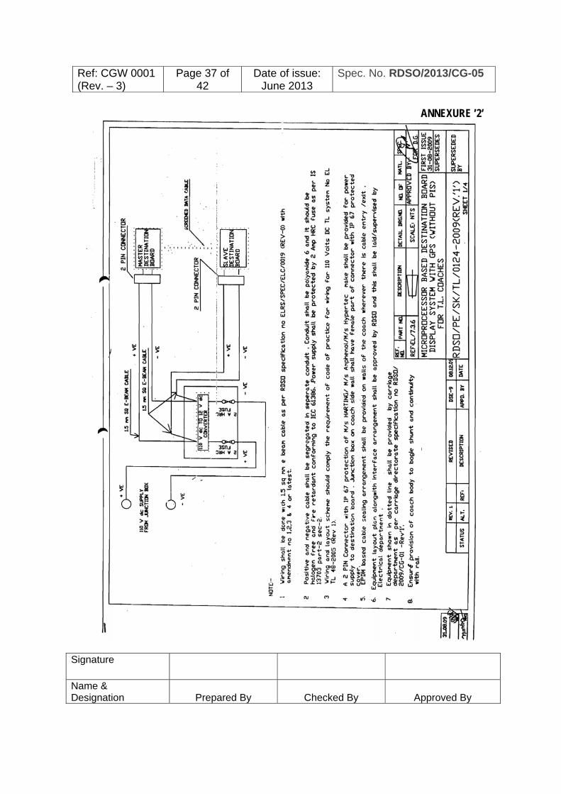
suitable HRC fuses. High voltage protection is to be provided. Connection diagram of power supply unit shall be as per Annexure‘2’
20.10 EMI Filter Assembly:
EMI FILTER ASSEMBLY is to be used to suppress any unwanted spikes and surges generated from the power lines or from the coach battery.
20.11 Wiring Assembly: Wiring assembly shall be neat and clean with suitable cable markers on every wire and proper sleeving. The wiring standard shall be as per RDSO/2006/SPN-144 specification.
21. Communication Protocol: Industry standard protocols like http, FTP, SMTP, IMAP etc. shall be used over standard IP network for all types of the communication modes for transfer of data, software files and reports generated. No vendor specific protocol or file or data formats shall be allowed, so that interoperability of the devices selected for the system may be ensured.
22. DATA BASE System will have capability to generate any new Train Number database and to store 100 train routes up and 100 train route down data. However this data shall be provided by coaching depot, conforming to clause no. 19.3.3 as per their requirement in the following format in Hindi, English and regional languages
Route No.
Train No.
Train Name
Starting Station and Regional Language
Destination Station and Regional Language
VIA (List of important station)
Software (as elaborated below) for feeding and editing data in Hindi, English and all Regional language as per 8th schedule of constitution of India and article 344(1) and 351 shall be provided by web server administrator. Supplier will do the necessary training and hand-holding support for making and editing database for first 3 months.
Software Requirement i) Setup files of computer software on a CD. ii) Control flow chart and algorithm for the control logic. iii) Operating manual of the software. iv) Facility to modify the display program through Base Monitoring Unit/PC.

Ref: CGW 0001 (Rev. – 3)
Page 30 of 42
Date of issue: June 2013
Spec. No. RDSO/2013/CG-05
Signature
Name & Designation
Prepared By
Checked By
Approved By
The system shall be user friendly to the maximum extent so that addition and alterations can be done by the Railway Engineer without the help of suppliers and programmer.
23. INSPECTION & TESTS BY MANUFACTURER / SUPPLIER: i) Unless otherwise specified all the tests shall be carried out at ambient
atmospheric conditions. For inspection of material, RDSO/SPN/144 shall apply. Inspection and testing shall be carried out to the effect that all requirements of this specification are complied with.
ii) Inspection shall be carried out for various types of boards, hardware modu les , for all its parameters, and software.
iii) PC based simulation facilities shall be created for demonstration of all the features of the CDIS. System shall have all the necessary hardware and software modules for this purpose along with Un-Interrupted Power Supply Unit. This shall be checked during inspection for the functional and performance requirement of the complete system as per specification.
24. Batch Testing of LEDs. 24.1 At least 0.01% of the LEDs of every procured lot shall be tested before use to the
dispersion angle test procedure. Lot wise test record shall be maintained which may be verified by the inspecting officials.
24.2 Manufacturer shall maintain proper account of LEDs being used. The record shall include various details like source of supply, procurement invoice no. and date, quantity, incoming rejection, lot-wise consumption etc. which may be verified by the inspecting officials.
24.3 LEDs used in LED display units shall be of high performance quality and from reputed manufacturers as stipulated by RDSO. The maximum junction temperature of a LED shall not be less than 1000C and epoxy used in the PCB shall have UV inhibitors.
24.4 Number of LEDs and their part number shall not be changed without prior approval of RDSO.
25. Routine Tests: The following shall comprise the routine tests and shall be conducted by manufacturer on every equipment and the test results will be submitted to the inspection authority before inspection. The application software in proper format shall also be submitted to the inspection authority in advance. i) Visual inspection of complete system ii) Insulation Resistance Tests iii) Performance test
Ref: CGW 0001 (Rev. – 3)
Page 31 of 42
Date of issue: June 2013
Spec. No. RDSO/2013/CG-05
Signature
Name & Designation
Prepared By
Checked By
Approved By
iv) Card-level functional tests on all the cards v) System level functional tests Any other tests shall be carried out as considered necessary by the purchaser
26. INSPECTION OF FINISHED PRODUCT BY INSPECTING AUTHORITY
26.1 Type Tests For type test, one complete system consisting of all type of display boards shall be subjected to following tests as applicable:
26.1.1 Environmental /Climate Tests: All the Environmental /climate tests shall be conducted as per RDSO/SPN/144.
i) Enclosure Unit Sealing Test
Testing of the specified units for degree of protection IP65is to be certified by one of the Government accredited testing laboratories.
ii) Shock and vibration testing Shock and Vibration testing of the complete system to be done to the standard of IS 60571/1 by one of the Government accredited testing laboratories.
Above test shall be repeated at 1000 units manufactured.
26.1.2 Endurance Test: Endurance test shall be conducted on the modules for continuous operation which shall be 30 days burning with all LEDs of the module in “on” condition using a test software. The lux level at a distance of 1m normal to the module shall be measured at the center normal position of the module 20 minutes after the beginning of the test. The Lux test shall be repeated at the end of the endurance cycle and reduction in lux level observed shall not be more than 5%. Unit shall be tested with a cycle of 10,000 operations of 2 minute “’on” and 1 minute “off”.
26.2 Acceptance Tests:
26.2.1 Sampling criteria : Constitute the acceptance tests, which shall be carried out by the inspecting authority for the purpose of acceptance on 20% of the lots (minimum2 each type of system) offered for inspection by the supplier: i) Visual inspection of complete system

Ref: CGW 0001 (Rev. – 3)
Page 32 of 42
Date of issue: June 2013
Spec. No. RDSO/2013/CG-05
Signature
Name & Designation
Prepared By
Checked By
Approved By
ii) Insulation Resistance Test iii) Performance Test iv) System level functional tests.
26.2.2 Visual Inspection: Each equipment of the system shall be visually inspected to ensure compliance with the requirement of this specification. The visual inspection shall broadly include: a) System Level Checking:
i) Constructional details. ii) Dimensional check. iii) General workmanship. iv) Configuration. v) Mechanical polarization on cards.
b) Card Level Checking: i) General track layout. ii) Quality of soldering and component mounting. iii) Conformal Coating. iv) Legend printing. v) Green /Black masking.
c) Module Level Checking: i) Indications and displays. ii) Mounting and clamping of connectors. iii) Proper housing of cards.
26.3 Performance test : All the units shall be tested for their functionality as required in service condition as per this specifications design requirements. To simulate such condition in test lab a PC based simulator shall be specially developed for this purpose by the manufacturer.
26.4 Insulation Resistance Test: Insulation Resistance Test shall be conducted as per RDSO/SPN/144.
26.5 Applied High Voltage Test:
Applied High voltage test shall be conducted as per RDSO/SPN/144
****************

Ref: CGW 0001 (Rev. – 3)
Page 33 of 42
Date of issue: June 2013
Spec. No. RDSO/2013/CG-05
Signature
Name & Designation
Prepared By
Checked By
Approved By
Part-III INFRASTRUCTURAL REQUIREMENT
1. Scope:
This section covers the infrastructural requirement for manufacturing and testing of the LED Destination board with Coach Diagnostic and Information System.
2. Requirements : All the vendors seeking registration with RDSO shall comply all the requirements mentioned below.
3. Manufacturing Facilities: 3.1. The manufacturer shall have adequate space and covered area with cemented
floor to accommodate the following. a) Damp free place for storage of raw material and finished products. b) Independent Manufacturing area c) Inspection area
3.2. Firm shall have following minimum M&P and Infrastructure at their works:
i) Automatic wave soldering machine or automatic SMD pick & place machine with Reflow oven.
ii) In Circuit Debugger / tester. iii) Ultrasonic PCB Cleaning Machine. iv) Regulated DC power supplies. v) Temperature controlled soldering and de-soldering work stations. vi) Electro static charge free work and storage area to prevent sensitive
components from damage during manufacturing, testing and storage. vii) LED illumination test fixture along with Dark Enclosure for measurement
of various parameters. viii) Micro computer based CAD work stations and developmental
workstations for hardware and software for CDIS. ix) Other regular tools like Measuring tape, Measuring scale, Magnifying
glass, screw drivers, cutting tools, crimping tools etc. used for manufacturing, electronic assembly line, inspection and testing of the LED destination board and CDIS.

Ref: CGW 0001 (Rev. – 3)
Page 34 of 42
Date of issue: June 2013
Spec. No. RDSO/2013/CG-05
Signature
Name & Designation
Prepared By
Checked By
Approved By
4. Testing Facilities: 4.1 Firm should have following minimum testing facilities at their works:
i) Burn in test chamber / Dry heat chamber. ii) Insulation tester. iii) Dual Beam Oscilloscope of 20 MHz bandwidth iv) Chromo Meter or Spectrometer v) Digital Millimeters : 3 and 1/2 Digit Display with facility of diode &
transistor testing with 1% accuracy vi) LCR meter. vii) Universal IC tester. viii) Megger (500 Volt) ix) PC based Simulator x) Test Jig xi) GSM/GPRS modem test set xii) Any other test equipment considered necessary.
4.2 The firm should have arrangement for periodical calibration of all the equipment’s and test instruments.
5 QUALITY CONTROL REQUIREMENTS 5.1 The firm should have acquired ISO: 9001certification from the agency accredited
by an accreditation body which is a part of International Accreditation Forum (IAF), and the product for which the approval is sought should be broadly covered in the scope of the certification for manufacture and supply.
5.2 The Quality manual of the firm for ISO: 9001 should clearly indicate at every stage the control over manufacturing and testing of the said railway product.
5.3 There should be a system to ensure the traceability of the product from raw material stage to finished product stage. The system should also facilitate to identify the raw material composition from the finish product stage.
5.4 It should be ensured that there is a Quality Assurance Plan for the product detailing the following various aspects. • Organisation chart • Process flow chart • Stage inspection details from the raw material stage to finish product stage. • Various Parameters to be checked and level of acceptance of such
parameters indicated and method to ensure control over them. • Disposal system of rejected raw material and components

Ref: CGW 0001 (Rev. – 3)
Page 35 of 42
Date of issue: June 2013
Spec. No. RDSO/2013/CG-05
Signature
Name & Designation
Prepared By
Checked By
Approved By
5.5 There should be at least one full time technologist having a minimum Master’s degree in relevant field with experience of at least 3 years or Bachelor’s degree in relevant field with experience of at least 5 years or a person with Diploma in relevant field with 12 years experience. He should be free from day-to-day production, testing and quality control responsibilities. He should be mainly responsible for development of a product, analysis of products, control over raw material, and corrective action in case of difficulties in achieving the parameters.
5.6 Ensure that the incharge of the Quality Control Section is having a qualification of minimum Master’s degree in relevant field with experience of at least 3 years or Bachelor’s degree in the relevant field with a minimum of 5 years’ experience or alternatively he should be a Diploma holder with minimum of 12 years’ experience. He should be actively involved in day-to-day activities of quality control / stage inspection / compliance of QAP etc.
5.7 The firm must ensure that proper analysis is being done on monthly basis to study the rejections at various internal stages and it is documented.
5.8 The firm should ensure that latest version all the relevant specifications, IS Standards are available with the firm.
6. DOCUMENTATION
Firm shall maintain the following documents/records: 6.1 A well-documented Quality Plan. 6.2 Incoming raw material register with Test Certificates references of suppliers and
internal test results. 6.3 Stage inspection results including finished products results. 6.4 Records of internal rejection and its analysis vis-à-vis action plan. 6.5 Records of final products inspection by external agencies (like RDSO), Non–
conformity reports and case analysis as well as action taken thereof. 6.6 Records for maintenance of dies/moulds. 6.7 Ensure that proper systems are available for dealing with customer complaint. 7 TRAINING
Training needs should be identified for all concerned officials and regular training shall be organised and imparted on maintenance of machines, quality assurance, safety parameters etc.

Ref: CGW 0001 (Rev. – 3)
Page 36 of 42
Date of issue: June 2013
Spec. No. RDSO/2013/CG-05
Signature
Name & Designation
Prepared By
Checked By
Approved By
ANNEXURE,’1’
Ref: CGW 0001 (Rev. – 3)
Page 37 of 42
Date of issue: June 2013
Spec. No. RDSO/2013/CG-05
Signature
Name & Designation
Prepared By
Checked By
Approved By
ANNEXURE ’2’

Ref: CGW 0001 (Rev. – 3)
Page 38 of 42
Date of issue: June 2013
Spec. No. RDSO/2013/CG-05
Signature
Name & Designation
Prepared By
Checked By
Approved By

Ref: CGW 0001 (Rev. – 3)
Page 39 of 42
Date of issue: June 2013
Spec. No. RDSO/2013/CG-05
Signature
Name & Designation
Prepared By
Checked By
Approved By

Ref: CGW 0001 (Rev. – 3)
Page 40 of 42
Date of issue: June 2013
Spec. No. RDSO/2013/CG-05
Signature
Name & Designation
Prepared By
Checked By
Approved By

Ref: CGW 0001 (Rev. – 3)
Page 41 of 42
Date of issue: June 2013
Spec. No. RDSO/2013/CG-05
Signature
Name & Designation
Prepared By
Checked By
Approved By
Annexure -3 PARAMETERS TO BE CHECKED DURING THE FIELD TRIAL: Sl.No.
Parameter to be recorded in the field trial
Compliance
Adequacy Remarks if any
1 Software for preparation of database of routes in PC/Laptop and interface with web server for data entry.
2 Uploading of route database /Modification/Replacing using Various option provided as well as through web server.
3 Recording coach health messages /alerts /reports of CDIS in MPUand synchronization in web server.
4 Train selection through web server, local Wireless network and manual selection in MPU directly.
6 Display of the destination board as per Presentation scheme defined in the specification.
7 Failure monitoring of the complete system and logging of the report in the MPU and synchronization of the report to web server.
8 Response time of the vendor for attending the complaints. Date of fitment and details of the firm along with contact address are required to be provided.
9 Downloading the daily log report of the Kms. earned by the coach.
10 Display quality and visibility of the destination board during daylight and other timings.
Data of the train routes shall be provided by the depot conforming to the clause no. 20 of the specification.

Ref: CGW 0001 (Rev. – 3)
Page 42 of 42
Date of issue: June 2013
Spec. No. RDSO/2013/CG-05
Signature
Name & Designation
Prepared By
Checked By
Approved By
ANNEXURE –4
UNDERTAKING AGAINST CARTEL FORMATION
We, ……………………………………. hereby, give an undertaking that as a Registered Vendor for manufacture and supply of LEDDESTINATION BOARD DISPLAY BOARD WITH COACH DIAGNOSTIC AND INFORMATION SYSTEMFOR IR BG COACHESwill not be a part of a cartel with other vendors and will be quoting competitive rates in the tenders invited by the Indian Railway/PUs.
We …………………………… are aware of the fact that the Registering Authority i.e. RDSO may de-list the name of our firm from the Master List of Approved Vendors if complaint is received about such cartel formation from any of the Railways/Production Units.
We confirm that the information furnished is correct to the best of our knowledge.
Seal and Signature (Authorised signatory of the firm)
Date : Place : Seal :