Embed Size (px)
Citation preview
Signature And seal of Bidder 1
SCHEDULE –B1
TECHNICAL SPECIFICATION
FOR
REROFITTING OF
GENERATOR PROTECTION RELAY SCHEME
OF UKAI HYDRO POWER STATION UNIT 1 TO 4
AND KADANA HYDRO POWER STATION UNIT NO.3 or 4
Signature And seal of Bidder 2
INDEX
SL. NO
CONTENT DESCRIPTION PAGE NOS.
1 SECTION I QUALIFYING REQUIREMENTS
FOR BIDDERS
3
2 SECTION II TECHNICAL SPECIFICATION 4
3 SECTION III ANNEXURES 31
4 SECTION IV TECHNICAL SCHEDULES 52
Signature And seal of Bidder 3
SECTION: I
QUALIFYING REQUIREMENT FOR BIDDERS
1. The bidder shall be original equipment manufacturer (OEM). The offered Relay have to
be designed, manufactured and tested as per relevant IS/IEC with latest amendments.
2. The minimum requirement of manufacturing capacity of offered type, size and rating of
Relays shall be five times of the tendered qty. The bidder should indicate manufacturing
capacity by submitting latest updated certificate of a Chartered Engineer (CE).
3. Relay / PROTECTION PANELS offered shall be of similar or higher rating and in service
for a minimum period of THREE (3) years and satisfactory performance certificate from
utilities like State Electricity Corporations, NTPC, PGCIL etc. in respect of this should be
submitted. The details shall be submitted in Schedule 5 for “Performance and Experience
Detail “
3. Bidder shall submit Details of orders for similar nature/jobs carried out along with
documentary evidence, performance certificate and their organization set up for such work
executed in past there years indicating the names of the organizations, order no and date.
4. The bidder should clearly indicate the quantity and single value contract executed during last
five (5) years for the offered product. Bidder should have executed one single contract
during last five years for the quantity equivalent to bid. The details should be submitted as
per format in Schedule 6 “Largest Quantity order Executed Details. “
5. Relay / PROTECTION PANELS offered shall have type test certificates from accredited
laboratory (accreditation based on ISO/IEC/Guide 25/17025 or EN 45001 by the national
accreditation body of the country where the lab is located.) as per IS/IEC/Technical
specification, not older than FIVE (5) years from the date of opening of technical bid.
6. The bidder shall guarantee for supplying maintenance spares and services as well as
repairing of relays for a period of the life expectancy of 15 years.
Signature And seal of Bidder 4
SECTION II
TECHNICAL SPECIFICATION
CONTENTS
Sr. No.
DESCRIPTION PAGE NO.
1.00.00 Intent Of Specification 05
2.00.00 Scope 05
3.00.00 Schedule Of Requirement 07
4.00.00 Standards 07
5.00.00 Climatic Conditions 08
6.00.00 General Description of the Project. 08
7.00.00 General Technical Requirement: - Panel 09
8.00.00 General Technical Requirement:-Relays 13
9.00.00 General Technical Requirement:-SCADA 14
10.00.00 Details Of Instrument Transformers, Power Transformers And Generator
15
11.00.00 Principal Technical Parameters 15
12.00.00 Tests 24 13.00.00 Inspection During Manufacturing 25
14.00.00 Quality Assurance Plan 25
15.00.00 Performance Guarantee 26
16.00.00 Deviation 26
17.00.00 Document Submission 26
18.00.00 Drawings / Data / Documents To Be Submitted By Bidder Along with The Bid
28
19.00.00 Drawings / Data / Documents To Be Submitted By Successful Bidder
28
20.00.00 Demonstration 28
21.00.00 Packing And Transport 28
22.00.00 Training 29
23.00.00 Supervisory Installation & Commissioning 30
24.00.00 Schedules 30
25.00.00 Guarantee For Maintenance Spares And Services 30 .
Signature And seal of Bidder 5
1.00.00 : INTENT OF SPECIFICATION
1.01.00 This specification is intended to cover design, engineering, manufacture, Fabrication ,
assembly, inspection and testing at manufacturer's works, packing & forwarding,
supply, delivery at Power House site, installation and commissioning of complete Pre
wired Generator Protection Relay Panel having Microprocessor base Numerical type
Generator & Transformer protection relay including required Trip relay , auxiliary
relay , TBs etc. in place of existing Generator relay Panel having Static and
Electromechanical relays provided for Generator Protection of Unit # 1 to 4 , at Ukai Hydro Power Station and Unit 3 or 4 of Kadana Hydro Power Station and
buyback of existing protection scheme at Ukai HPS as specified hereunder & as
given in the schedule of requirements. The scope also includes supply of spare set of
relays for protection of Generator , Generator Transformer and UAT similar to
supplied in above protection panels.
1.02.00 It is also intended to have Interfacing of relays and communication system for DR
work station application and SCADA application without control function for the
relays to be supplied for all units of Ukai Hydro station as mentioned in (1.01.00)
above. The DR work station should be able to communicate with all relays for DR
downloading, viewing, Parameterisation etc. The SCADA application should have
suitable software and interface for viewing status of field equipments like Isolators,
Circuit breakers etc. and viewing parameters in the Single line diagram graphic
prepared in the software supplied. No. of binary inputs for field equipments status will
be 250.
1.03.00 All drawings and Annexure appended to this specification shall form part of this
specification and supplement the requirement specified herein. The specification shall
be read and construed in conjunction with the drawings and annexure to determine the
scope of work and terminal points.
1.04.00 As existing relays have been phased out and spares are not available, it has become
necessary to replace existing relays with panel. Modification required in the existing
schemes / wirings, for matching of new numeric protection relay scheme including
design , programming , configuration , setting calculation , drawing preparation ,etc.
to suit the requirements of existing protection scheme shall be covered under scope of
contract. Proposed scheme depending on existing protection requirement have
been indicated at Annexure IIIB & VIII-B , however bidder will study the existing scheme and accordingly may offer scheme as per offered relay architecture provided the scheme should cover all the functions / protection as per requirement considering CT/PT inputs indicated to have reliable scheme.
1.05.00 It is also intended to include complete relay application check and final relay settings
calculations to confirm suitability of new relays for the existing equipments to be
protected / existing relays both technically as well as dimensionally.
1.06.00 The bidder shall visit the site and get him acquainted with the actual requirements of
site prior to quoting rates. No claims for inadequate description of the scope shall be
entertained at a later date.
1.07.00 It is not the intent to completely specify all details of design and construction herein.
Nevertheless, the equipment and installation shall conform to high standards of
engineering design and workmanship in all respects and shall be capable of
performing continuous operation in a manner acceptable to the Purchaser. Reliability,
availability and maintainability are of the utmost importance to the Purchaser in the
design of the equipment described herein.
2.00.00 SCOPE OF BIDDER 2.01.00 The scope of supply shall include but not limited to FOR destination supply of Pre
wired Complete Panel with comprehensive numeric relays for Generator , Generator
Signature And seal of Bidder 6
Transformer and Unit Auxiliary Transformer protection including Numerical
Protection relay having sufficient no. of Binary Input & Out put and Analogue Input
channels, Auxiliary relay , Tripping relay , TBs , Wires , Indicators , Test Switches /
Sockets , Test plugs , Stabilising resistors , illumination , pushbuttons , earth links etc.
to provide total functionality of protection for Generator , Generator Transformer ,
UAT and integration of various functions in each unit as per existing and new
proposed protection scheme and logic.
2.02.00 Software & Hardware for communication with relay , required accessories , Binary
and Analogue input status and measurement interface cards & equipments , com
ports, connectors , networking accessories , cable , PC , suitable furniture for DR
work station and SCADA application (without control) referred above shall be part
of the scope of supply
2.03.00 The Bidder shall study the existing scheme of protection for Generator , Transformer , UAT and associated equipments and accordingly offer complete protection scheme of Protection covering all existing protections and additional functions as available in the offered numerical relays. There should be sufficient number of Analogue input, Binary Input, Binary Output to suit the requirement of protection function and logic. ( Proposed scheme depending on existing protection requirement have been indicated at Annexure IIIB & VIII-B , however bidder will study the existing scheme and accordingly may offer scheme as per offered relay architecture provided the scheme should cover all the functions / protection as per requirement considering CT/PT inputs indicated to have reliable scheme.) However final scheme and application will be decided after discussion with bidder during technical scrutiny of the offer.
2.04.00 The existing scheme of protection, CT, PT detail, Transformer detail etc. have been
furnished with this specification , however bidder should visit at each site to access
the requirement , quantum of work , scheme logic , location, dimension detail etc.
before submitting the bid. The bidder shall submit complete detail of the scheme to be
offered viz. relay, panel, configuration of scheme logic, protection function and
features etc. ( Note:- at Kadana HEP the generator is designed for operating on
Generator and Motor mode both , the same should be considered during setting )
2.05.00 The characteristics and relay setting ranges shall be decided by the bidder. During
detailed engineering, co-ordinated relay settings shall be worked out by the successful
bidder and the calculations/time-charts shall be submitted for approval to
Owner/Consulting Engineer.
2.06.00 Trip Matrix required for implementing various class tripping schemes shall be
provided by the Contractor and shall be indicated in block interlock diagrams to be
submitted.
2.07.00 The scope includes preparation and furnishing of settings , calculations , installation,
commissioning instructions and maintenance manual for all protections with all
operational feature/optional feature
2.08.00 The scope includes preparation and furnishing softcopy as well as hardcopy of four
sets of all types of as built drawings including schematic, internal external cable
connection drawings, wiring schedules, electrical internal circuits indicating
measuring points and measuring values, relay data sheet, relay setting calculation.
2.09.00 The scope includes supply of wires, lugs, connectors, screws, nut bolts etc required
for retrofitting and other accessories which are necessary for satisfactory operation of
complete relay scheme though not individually or specifically mentioned herein.
2.10.00 The disconnection of existing control wiring, indication, annunciation, CT, PT
connections from all the protection panels and removal of existing relays, wires,
terminal blocks etc. Removal and shifting of removed panel at place directed by
engineer in charge.
2.11.00 Installation of New panel in place of existing removed panel including shifting from
storage with required mounting hardware, blanking plates, Glands, earthing strip,
relevant fabrication etc. with covering of remaining portion of Cable trench.
Signature And seal of Bidder 7
2.12.00 The scope includes wiring/terminations, grounding etc and also wiring modifications
to include all logic as per existing protection scheme.
2.13.00 Supply and mounting of all equipment as specified in this specification together with
such auxiliary equipment and materials as required. The tenderer shall indicate
make, type and designation of all equipments in the bid. 2.14.00 Complete internal wiring of equipment and terminal blocks and wiring between
adjacent panels. Design and manufacture of relays and relay assemblies to meet the
requirement of various protection schemes, specified in this specification or not.
2.15.00 The testing and commissioning of modified and retrofitted control and relay panels
including testing and commissioning of relays for all functions/logics in totality and
furnishing of test certificates.
2.16.00 The scope includes Commissioning of additional features /logics other than existing
scheme as per requirement with accessories and auxiliary equipments if required.
2.17.00 Any defect arises in Panel , Communication equipments , Software , relay , auxiliary
relay and found defective during commissioning at site shall be replaced free of cost,
which include transportation also.
2.18.00 The scope includes to time synchronize the supplied relay with existing GPS.
2.19.00 The scope includes training to site engineers at supplier’s works and site free of cost.
The minimum no. of engineers for training at supplier’s works shall be five.
2.20.00 Any other works and supply which could not be specified above but are necessary to
complete the job shall be the responsibility of the bidders.
2.21.00 Keeping in view, the above scope of work, the bidder shall furnish sequence of
activities to be carried out to avoid / minimize the generation loss, likely to occur
during above works. The bidder shall note that above work shall be completed within
shut down period. The bidder shall also note that there may be uncertainty of
Shutdown due to grid exigency. However, no additional cost/ compensation on this
account shall be entertained.
3.00.00 SCHEDULE OF REQUIREMENT 3.01.00 The requirement of Panel, Relay and Communication network etc. to be supplied
against this specification and their required deliveries are given in Commercial Terms
and Conditions and also in the ANNEXURE-I 3.02.00 Delivery instructions shall be issued to the successful bidder after placement of orders
and after inspection and testing of Panels and relays at manufacturer’s works.
3.03.00 Recommended spares
The tenderer shall furnish in his offer, a list of recommended spare with unit rates for
PROTECTION PANELS that may be required for trouble free operation for a period of
10 years. The purchaser reserves the right of selection of items and quantities of these
spares to be ordered. The tenderer is bound to supply spares for maintenance as and
when required for service life of the protections as per clause No.24.00.00
3.04.00 Recommended tools, testing kits, test handles etc. The tenderer shall furnish in his offer a list of recommended testing kit, tools with unit rates for PROTECTION PANELS those may be required during testing and
commissioning of said panel, off line as well as on line testing. The purchaser reserves
the right of selection of items and quantities to be ordered.
4.00.00 STANDARDS 4.01.00 Unless otherwise specified elsewhere in this specification, all equipment and
materials shall be designed, manufactured and tested in accordance with the latest
revisions of Indian Standards or British Standards and International Electro-Technical
Commission (IEC) Standard available at the time of placement of order. The supplier
shall submit the copies of the relevant standards applicable to the relay.
Signature And seal of Bidder 8
4.02.00 Equipment meeting with any other standard, which ensures equal or better quality,
may be accepted. Where the equipment conforms to any other standard, the salient
points of difference between the standards adopted and the above standards shall be
clearly brought out in the tender. A certified copy of such standard in English version
shall be submitted along with the bid. 4.03.00 A list of applicable Standards is given in Annexure II
5.00.00 CLIMATIC CONDITIONS: 5.01.00 The climatic and isoceraunic conditions at site are given below:
5.02.00 The equipment offered shall be capable for continuous satisfactory operation under
the above conditions.
5.03.00 Since the equipment offered shall be used in the Hydro power station which is at the
Dam Location the offered equipment shall be suitable for polluted atmosphere.
5.04.00 Equipment covered in this specification shall be suitable for indoor installation.
6.00.00 GENERAL DESCRIPTION OF THE PROJECT: 6.01.00 The equipment specified herein will be installed at Ukai Hydro Power Plant and
Kadana Hydro Power Plant of Gujarat State Electricity Corporation Limited.
6.02.00 The site is located at Ukai Dam about 100 Kms. from Surat and Kadana Dam Located
at about 160 Kms from Vadodara.The nearest Railway Station is Songadh of Western
Railway from Ukai and Godhara from Kadana.
6.03.00 The Generation voltage is 11kV, which is stepped up to 220 kV by means of 3-phase
Power Transformers (GTs). The connection between generator terminals and GT
would be by means of bus-duct up to 11kV LT side terminals of GT.
6.04.00 The connections from the GTs to Take-off gantry would be by means of overhead
conductors. .There is one No. 11 kV /415 V Unit Aux. Transformer to cater auxiliary
load per unit.
6.05.00 The existing protective functions and other diagram/detail as shown below are being
appended to this specification for the guidance of the bidders, however, bidders are
advised to get themselves acquainted with actual inputs at site.
6.05.01 Ukai Hydro Power Station Unit 1 to 4
(i) Existing Protection Scheme at Annexure III-A
(ii) Proposed Protection Scheme at Annexure-III-B (iii) Existing Panel GA Drawings at Annexure IV
(iv) CT,PT and Relay Details at Annexure V
(v) Existing Relay settings at Annexure VI
(vi) Details of Generator , Generator Transformer & UAT at Annexure VII
a Maximum ambient temperature (º C) 50
a Maximum ambient temperature in shade (º C) 45
b Minimum ambient temperature in shade (º C) 03
c Maximum daily average ambient temperature (º C) 40
d Maximum yearly average ambient temperature (º C) 32
e Relative humidity (%) 10 to 100
f Average annual rain fall (mm) 1150
g Average number of thunder storms (days/year) 30
h Height above Sea level (Meters) Not exceeding 1000
i Maximum wind pressure (Kg/m2) 150
j Earth quake acceleration 0. 2 g to 0.3 g
Signature And seal of Bidder 9
6.05.02 Kadana Hydro Power Stations Unit 3/4
(i) Existing Protection Scheme at Annexure VIII-A
(ii) Proposed Protection Scheme at Annexure VIII-B
(iii)Existing Panel GA Drawings at Annexure IX
(iv) CT,PT Relay Details at Annexure X
(v) Existing Relay settings at Annexure XI
(vi) Existing Relay , CT & VT detail at Annexure - XII
(vii) Details of Generator , Generator Transformer & UAT at Annexure XIII
7.00.00 GENERAL TECHNICAL REQUIREMENTS: 7.01.00 PANEL:
7.01.01 Existing Generator relay Panel at Ukai Hydro Power station is of Duplex type with relay and control equipments together. The front side panel is having two compartments having control switches, indications, meters, some protective relays etc. and associated wiring. The rear side panel is having protective relays with associated wiring. The schematic of the existing panel is attached with this specification. Looking to site requirement the front side panels will not be removed but blanking plates shall be provided in place of removed relay. The rear panel having only protective relay shall be removed and new panel to be supplied at Ukai shall be designed to have matching dimension and colour shade with existing remaining panel and space available to house all required relays ,equipments , accessories etc. as specified in this specification for all four units of Ukai Hydro station.
7.01.02 Existing Generator relay panel at Kadana Hydro Power station is of Simplex type having two compartments. The schematic of the existing panel is attached with this specification. The existing complete panel shall be removed and the new panel to be supplied at Kadana shall be designed to have matching dimension and colour shade with exiting other panels to house all required relay , equipments , accessories etc. as specified in this specification for one unit of Kadana Hydro station.
7.01.03 The Panel Dimensions shall depend on site requirement and space available.
The details should be finalized during the engineering stage by the successful
bidder after getting approval from GSECL. 7.01.04 Panel shall be completely metal enclosed and shall be dust, moisture and
vermin proof to meet the requirement of IP 51 of IS: 2147.
7.01.05 The panel shall be free standing , floor mounting type , and shall comprise
rigid , welded structural frame enclosed completely with specially selected
smooth finished cold rolled sheet steel of thick ness not less than 3.0 mm for
load bearing members ( Front Panel , base frame , door frame) and 2.0 mm
for non load bearing members ( side panel , cubicle roof , door). There shall
be sufficient reinforcement to provide level surfaces , resistance to vibration ,
and rigidity during transportation and installation.
7.01.06 All doors and removable covers shall be gasketed all round with neoprene
gaskets, ventilating louvers with screen and filters.
7.01.07 Design, material selection and workmanship shall be such as to result in neat
appearance inside and out side with no weld, rivets or bolt heads apparent
from outside and with all exterior surface true and smooth.
7.01.08 Cable entries to the panel shall be from the screwed type removable bottom
plates of the panel
7.01.09 The panel should be completely wired and to be fixed with all accessories like
Relays , Auxiliary relays , TBs , ( Disconnecting type TBs with shorting
Signature And seal of Bidder 10
arrangement for CT , PT) , Earthing Bus , Terminal connection for CT – PT
cables, Switches , Illumination , space heaters , Power sockets , Connection to
Relays , Ethernet switch , Computer etc.
7.02.00 AUXILIARY SUPPLY:
7.02.01 The bidder will have to reconnect the existing AC / DC supply for Switches,
Panel illumination, space heater etc. and supplies for control and protections
of existing panels. 7.02.02 The relays shall be suitable for 220V (+10% to -15%) DC supply
7.03.00 PANEL INTERNAL WIRING
7.03.01 All wiring shall be carried out with 1100V grade single core multi strand
flexible copper conductor wires with HRPVC insulation and shall be flame
retardant, vermin and rodent proof. The current carrying capacity of wire
shall be adequate for the duty assigned to it considering short circuit
condition and shall have sufficient flexibility to facilitate proper termination
at any location. Colour coded wires (red, yellow, blue, black) shall be used
for CT, VT and CVT secondary connections. The copper conductor used for
internal wiring be as follows:
a) All circuits except instrument transformer circuit of 1.5 Sq mm per lead
b) CT circuit - one 4 Sq mm per lead.
c) VT circuits one 2.5 Sq mm per lead.
d) Energy metering – 4 Sq mm per lead for both PT & CT circuits.
7.03.02 Auxiliary bus wiring for AC and DC supplies voltage transformer circuits,
annunciation circuits and other common circuits shall be provided near the
top of the panels running throughout the entire length of the panels.
7.03.03 The wire numbers shown in the wiring diagram shall be in accordance with
IS375/BS152/BS156. All wires directly connected to trip circuit breaker or
devices shall be distinguished by addition of a red colored or lettered ferrule.
Number 6 and 9 shall not be used.
7.03.04 Panel wiring shall be securely supported, neatly installed by lacing and tying,
readily accessible and connected to equipment terminals and terminal blocks.
Flame retardant, plastic wiring channels/troughs with strap on plastic covers
shall be used for this purpose. Sufficient space in channel for modification of
wiring shall be kept.
7.03.05 Accidental short circuiting of certain wires is likely to result in malfunction of
equipment, such as closing or tripping of a breaker or positive and negative
wires, these wires shall not be terminated on adjacent terminal blocks.
7.03.06 The unused space on the front or rear of the panels shall be kept clear of
wiring to facilitate addition of devices without rewiring associated portion of
the panels.
7.03.07 Wire termination shall be made with solder less crimping type of tinned
copper lugs which firmly grip the conductor. Insulation sleeves shall be
provided at all the wire terminations. Engraved core identification plastic
ferrules, marked to correspond with panel wiring diagram shall be fitted at
Signature And seal of Bidder 11
both ends of each wire. Ferrules shall fit tightly on the wire and shall not fall
off when the wire is disconnected from terminal blocks.
7.03.08 The bidder shall be responsible for the completeness and correctness of the
internal wiring and for the proper functioning of the connected equipment.
7.03.09 Terminations on T.B. shall be grouped function wise on one region of T.B.
(may not be full T.B) to take outlet connections in one cable for the function.
7.04.00 LABEL
7.04.01 All front mounted equipment as well as equipment mounted inside the panels
shall be provided with individual labels with equipment designation
engraved. The labels shall be mounted directly below the respective
equipment.
7.04.02 All the front mounted equipment shall also be provided tag numbers
corresponding to the ones shown in the panel internal wiring to facilitate each
tracing of wiring. These labels shall be mounted directly by the side of the
respective equipment and shall not be hidden by the equipment wiring.
7.04.03 Labels shall be made of Aluminum anodized plate P.V. Castings. Labels shall
have white letters on block background. All relays shall be given standard
abbreviation numbers with name of device, corresponding to the ones shown
in the panel internal wiring.
7.05.00 EARTHING
7.05.01 All metallic cases of relays, instruments and other mounted equipment shall
be connected to earth bus by copper wires of size not less than 2.5 sq. mm.
The colour of the earthing wire shall be green.
7.05.02 Looping of earth connections which would result in loss of earth connection
to other devices when the loop is broken shall not be permitted. However,
looping of earth connections between equipment to provide alternative paths,
to earth bus shall be provided.
7.05.03 VT, CVT and CT secondary neutral or common lead shall be earthed at one
place only. Such earthing shall be made through links, so that earthing may be
removed from one group without disturbing continuity of earthing systems
for other group.
7.05.04 A separate earthing point shall be provided in the panel for cable screens of
static equipment, insulation between two earths prior to connections of the
two earths to the Purchaser’s earthing grid, shall withstand a test voltage of
500V for 1 minute (or higher insulation resistance of not less than 1 meg-
ohms at 500V) connection between the screen terminals and the screen earth
– point shall be jumper wires. Connection of this earth point to the station
earth shall be carried out by Purchaser.
7.06.00 INDICATING LAMPS
7.06.01 Indicating lamps shall be of miniature switch board/LED type suitable for
panel mounting with series resistors preferably built in the main assembly to
avoid short circuiting of control supply in the event of short circuit of lamps.
The lamps shall be rated for 220VDC unless otherwise specified. Lamp
covers shall be of screwed type, unbreakable and moulded from heat resisting
material and shall be translucent to diffuse light & coloured as specified.
7.07.00 INTERIOR LIGHTING
Signature And seal of Bidder 12
7.07.01 The panel: shall be provided with fluorescent (CFL Lamp) lighting fixture
rated for 240V AC supply, controlled by panel door switch and fuse. The
number of such fluorescent lighting fixtures shall be 1 no. per panel.
7.07.02 The panel shall be provided with 240V, 50Hz. 15 A, 3 pin universal socket
with switch. The socket with switch shall be mounted inside the panel at
convenient location.
7.08.00 TERMINAL BLOCKS
7.08.01 Terminal blocks shall be 1100 V grade, 45 amps rated, one piece molded,
complete with insulated barriers, stud type, melamine housing brass
terminals, washers, brass nuts and brass lock nuts and identification strips.
Markings on the terminals strips shall correspond to wire number on the
wiring diagrams. Not more than 2 wires shall be connected to any terminals.
7.08.02 Terminal blocks for CT, CVT and VT secondary leads shall be provided with
test links and isolating facilities. CT secondary wiring should be such that it
can connect additional circuit in series.
7.08.03 All spare contacts and terminals of the panel mounted equipment and devices
shall be wired up to terminal blocks with ferrule numbers starting with U.
7.08.04 Unless otherwise specified, terminal blocks shall be suitable for connecting
the following conductors of purchaser’s cables on each side.
i) :All DC and auxiliary AC circuits -- minimum one of 2.5mm2 copper
ii) :All CT & PT circuits -- minimum two of 2.5mm2 copper
7.08.05 Moulding materials shall be self extinguishing or resistant to flame
propagation, substantially non hydroscopic and shall not carbonized when
tested for tracking. The insulation between any terminal and frame work
between adjacent terminals shall with stand test of 2kV RMS for one minute.
The molding shall be mechanically robust to withstand handling while
making terminations.
7.08.06 Easily removable Protective transparent plastic covers for placing over the
live parts of the terminal blocks shall be provided invariably.
7.09.00 PAINTING
7.09.01 All sheet steel work shall be phosphated in accordance with the following
procedures and in accordance with IS; 6005 `Code of Practice for
phosphating iron and steel’.
7.09.02 Oil, grease, dirt and swart shall be thoroughly removed by emulsion cleaning.
7.09.03 Rust and scale shall be removed by pickling with dilute acid followed by
washing with running water, rinsing with slightly alkaline hot water and
drying.
7.09.04 After phosphating, through rinsing shall be carried out with clean water
followed by final rinsing with dilute bi-chromate solution and oven drying.
7.09.05 The phosphate coating shall be sealed by the application of two coats of ready
mixed, stowing type zinc chromate primer. The first coat may be `Flash
dried’ while the second coat shall be stowed.
7.09.06 After application of the primer, two coats of finishing synthetic enamel paint
shall be applied, each coat followed by stowing. The second finishing coat
shall be applied after completion of tests.The panel/sheet shall have colour
confirming to shade of existing panel.
7.09.07 Each coat of primer and finishing paint shall be of a slightly aesthetically
pleasing appearance free from dirt and uneven surface.
7.09.08 The bottom plate shall be painted with an anti corrosive paint.
7.09.09 The paint thickness shall be 60-100 microns for powder coating.
Signature And seal of Bidder 13
7.10.00 MOUNTING 7.10.01 All equipment on front of panel shall be mounted flush
7.10.02 Relays shall be mounted such that removal and replacement can be
accomplished individually without interruption of service to adjacent
equipment.
7.10.03 No equipment shall be mounted on the doors without prior approval of the
purchaser.
8.00.00 GENERAL TECHNICAL REQUIREMENTS :RELAYS 8.01.00 The general requirements for the protective relays are described here under however;
all relays shall in general comply with the technical specifications mentioned under
clause 11.00.00 “Principal Technical Parameters”
8.02.00 All relays shall confirm to the requirements of Standards listed in Annexure II.
Equipments meeting any other authoritative standard, which ensures equal or better
quality than the standards mentioned shall also be acceptable. Equipment for which
Indian Standards are not available, the relevant British standards and IEC
recommendations will be applicable. Please attach photocopy of all such standards
according to which the equipment has been offered.
8.03.00 Relays shall be suitable for flush mounting on the front with connections from the
rear.
8.04.00 All protective relays shall be with proper on line testing facilities without isolation
from TB where inputs viz CT/ PT and DC are wired. All main relays shall be
provided with test plug to test the relay on line. Necessary test plugs/ test handles per
panel shall be supplied loose and shall be included in contractor’s scope of supply.
8.05.00 All AC operated relays shall be suitable for operation at 50 Hz. AC voltage operated
relays shall be suitable for 110V VT secondary and current operated relays for 1or 5
amps. CT secondary. All DC operated relays and timers shall be designed for the DC
voltage specified, and shall operate satisfactorily between 80% and 110% of rated
voltage. Voltage operated relays shall have adequate thermal capacity for continuous
operation.
8.06.00 Supervision relays having sufficient nos. of contacts for annunciation, blocking and
permissive function etc., to supervise healthiness of Auxiliary supply, PT supply, Trip
relay healthiness, Trip circuits shall form part of the scheme to be supplied.
8.07.00 The protective relays shall be suitable for efficient and reliable operation of the
protection scheme described in the specification. Necessary auxiliary relays and
timers required for interlocking schemes, multiplication of contacts, monitoring of
control supplies and circuits, lockout relay monitoring circuit etc. shall be provided.
8.08.00 All protective relays, auxiliary relays and timers except the lockout relays and
interlocking relays specified shall be provided with self-reset type contacts. All
protective relay and timers shall be provided with externally hand reset positive action
operation indicators with inscription. All protective relays, which do not have
8.09.00 Built-in hand-reset operation indicators shall have additional auxiliary relays with
operating indicators (flag relays) for this purpose.
8.10.00 No control relay which shall trip the power circuit breaker when the relay is de-
energized shall be employed in the circuits.
8.11.00 Any alternative/ additional protections or relays considered necessary for providing
complete effective and reliable protection shall also be included in the scope of
supply.
8.12.00 Provision shall be made for easy isolation of trip circuits of each relay for the purpose
of testing and maintenance.
8.13.00 The setting ranges of the relays offered, if different from the ones specified shall also be acceptable if they meet the functional requirements.
Signature And seal of Bidder 14
8.14.00 All relays and their drawings shall have phase indications as R-Red, Y-Yellow and B-
Blue.
8.15.00 Wherever numerical relays are used, the scope shall include the following:
8.15.01 The relay shall have Ethernet / USB / RS232 /optical port on front side
for communication with Laptop/Desktop and on rear side RS485 /
Ethernet / USB / fibre optic port shall be provided for rear
communication. Necessary converter for communication with PC /
Laptop shall be part of scope of supply.
8.15.02 Necessary licensed copy of software and hardware to up/ down load the
data to/from the relay from/to the personal computer installed in the sub
station shall be provided. Relay shall be looped by Fiber Optic/
twisted wire Cables up to PC (DR work station at Ukai hydro) 8.15.03 The relay shall have suitable communication interface on rear side for
the IEC 61850 standard for station communication.
8.15.04 The relay shall be supplied with IRIG port for time synchronisation with
GPS. The relay shall also have facility for time synchronisation through
binary input also.
8.15.05 The relay shall have sufficient no. of Analog Inputs for CT – VT of
suitable rating to include all protection functions intended in this
specification. Binary Input and Out put contacts
8.15.06 The software shall be suitable for operations like switching, retrieval of
information or changing of setting groups, retrieve oscillographic fault
data from the relay memory and to store fault record data as
oscilloraphic records in standard COMTRADE format. The software
shall be suitable to provide oscilloraphic data into several different
graphical representations that can be used to analyze the fault or event
captured by the relay. It shall also be possible to calculate additional
values from the captured signals and displaying analog curve with time
base phasor diagram locus diagrams, harmonic graphs etc. Automatic
upload of DR files should be possible.
8.15.07 The relay shall be supplied with all the original customized licensed
software, IO Cards, required cable for local or remote communication,
disturbance uploading, disturbance evaluation etc
8.16.00 All not used terminal shall also be provided with screws washers, lugs etc. as for used
terminal.
8.17.00 The type test offered for relay shall be supplied with full options of protection and
control functions mentioned in the catalogue.
9.00.00 GENERAL TECHNICAL REQUIREMENTS: SCADA SYSTEM for UKAI Hydro Station
9.01.00 At Ukai Hydro Station Unit 1 to 4 the Interfacing of all supplied relays with dedicated
PC shall be carried out. The relays shall be wired up with communication system for
DR work station application and SCADA application without control function.
9.02.00 The DR work station should be able to communicate with all relays for DR
downloading, viewing, Parameterisation etc. 9.03.00 The SCADA application should have suitable software and interface for viewing
status of field equipments like Isolators, Circuit breakers etc. and viewing parameters
in the Single line diagram graphic prepared in the software supplied. 9.04.00 The software should have OS window based platform. 9.05.00 The system should have event history recording and retrieving capability. 9.06.00 The time resolution for event recorded should not be more than 1 ms. 9.07.00 The protocol used should be open protocol for communication. If the protocol used is
of proprietary nature then use of Open protocol should also be possible without major
changes.
Signature And seal of Bidder 15
9.08.00 No. of binary inputs for field equipments (i.e. breaker, isolator, switches etc.) status
will be at least 250 for system. 9.09.00 No. of circuits for which metering parameters to be monitored in SCADA are 40 and
accordingly no. of analogue points shall be suggested by bidder. The bidder shall also
indicate clearly the method of connection, CT-PT input, required equipments etc. as
per site requirement. 9.10.00 Necessary PC, interfacing equipments, cable, Software, hardware & accessories,
furniture, panel etc. shall be part of this system.
9.11.00 Licensed version of software, Operating system, Office application, anti virus with
original media software shall be part of the supply.
9.12.00 Bidder should indicate exact detail of software and required hardware with its
features, facilities and application with offer.
9.13.00 The bidder should furnish configuration and specification of PC, Hardware,
interfacing equipments etc. with bid. The specification should be such as to suit the
existing requirement of the project; however the same will have to be approved from
GSECL before finalisation of requirement in detail order.
9.14.00 The software should have capabilities to create user defined graphics having desired
input configuration in the created screen depending on binary input.
9.15.00 The interfacing hardware & software should be expandable to suit addition of future
requirement of binary input.
9.16.00 Suitable capacity of UPS having one hour back up shall be supplied for SCADA
equipments and PC
9.17.00 The bidder should submit clear bill of material required for the proposed data
acquisition system with schematic and on basis of which requirement shall be
finalised in detail order.
9.18.00 All the equipment except field equipments, supplied should be properly housed in a
suitable IT rack or panel
9.19.00 Necessary cabling including supply for binary input for status shall not be in the scope
of bidder; however the successful bidder shall provide sufficient technical information
for the same during execution.
9.20.00 Required cable for communication from relay, interfacing panel, PC, networking
equipment etc. including supply , laying , termination shall be in the scope of bidder.
9.21.00 The bidder should demonstrate the offered scheme at site if demanded by purchaser.
9.22.00 Procurement shall be finalised on the basis of evaluation of performance and
applicability of the system for software and hardware offered.
10.00.00 DETAILS OF INSTRUMENT TRANSFORMRS, POWER
TRANSFORMRS AND GENERATOR. 10.01.00 The various detail of CTs, PTs, transformers and generators , existing scheme , relay
setting etc. for Ukai Hydro and Kadana Hydro Stations are attached at Annexure III to XIII
11.00.00 PRINCIPAL TECHNICAL PARAMETERS OF RELAY &
SCHEME. 11.01.00 The protective gear shall be as fast in operation as possible, so as to maintain the
maximum stability under fault conditions. The protective scheme shall provide
suitable protection for the individual equipment and at the same time ensure proper
operation of the entire protective system as a coordinated whole. Various protective
systems shall be designed to isolate only the faulty circuits and to avoid
indiscriminate tripping of healthy circuits. The protective scheme shall not be
susceptible to incorrect operation as a result of transient phenomenon, which may
arise during disturbances on the system.
Signature And seal of Bidder 16
11.02.00 The experience on various power systems in India has shown that a great majority of
system faults originate as earth faults, the no. of phase faults being comparatively
small. Special attention shall therefore, be given to the problem of providing a reliable
and high-speed earth fault protection. The phase faults should also be cleared in
minimum possible time in order to minimise damage and to maintain synchronous
stability. 11.03.00 All auxiliary relays, matching CTs, PTs and various timer relays etc. to complete the
protection scheme, shall be part of the bidder's scope of supply. The successful bidder
shall also recheck parameters of CTs and lead wire.
11.04.00 The electrical protection scheme proposed to be adopted for Unit comprising of
Generator, GT & Aux. Transformer shall have following functions
11.05.00 The protection system shall comprise pre-engineered modular or discrete self-
contained system comprising multifunction numerical relays (interfaced with
computer system for Ukai Hydro). In addition to the relays/protections mentioned in
this specification, any additional protections/relays considered necessary by the
Bidder for his system shall be included and offered by the Bidder. Licensed software
to read, set, configure and analyze the relay shall also be supplied. (along with
Computer system at Ukai Hydro system)
11.06.00 DC auxiliary supply shall be supervised by supply supervising relays. The NC
contact of the relays shall be delayed on drop off by approximately 100 to 200 m
sec. for annunciation in CRT / Generator control desk. The relay shall be provided
with flag indicators wherever required. White colour supervision lamps of clustered
LED type shall be provided on GRP to indicate availability of DC supply.
11.07.00 The relays shall be provided with continuous self-diagnostic facilities to indicate the
location of the failed component when pre-engineered protection system is offered.
Apart from this, facilities for comprehensive testing with external test kits shall also
be provided.
11.08.00 In addition to the contacts required as per schemes, Contractor shall wire out to the
terminal block at least one NO & one NC spare contacts of each of the relays.
11.09.00 The protection scheme shall include all the necessary contacts to achieve the functions
required, alarms in CRT, annunciation windows, sequence event recorder and for
Control room control panel annunciation wherever required. Contact multiplication
relays for generator circuit breaker and associated isolators shall be provided for this
purpose.
11.10.00 Additional Features
i The relay shall have a local friendly password-protected user man-machine interface
(MMI) comprising of a 2-3 line alphanumeric LCD display and a soft touch key pad to
access the settings, events and records in the relay.
i Optically isolated inputs & outputs (digital & analog)
i Digital signal processing
i Built-in circuit breaker failure protection
i Monitoring of CB trip circuit, CB condition and status
i Supervision of CTs & VTs
i Complete mechanical/electrical & atmospheric environmental protection/immunity as
per relevant standards.
i The protection system shall have facility to synchronise its time generator from
common time synchronisation from master clock of GPS system.
i The protection system shall have programmable scheme logic, multiple setting groups,
programmable settings and programmable characteristics.
Signature And seal of Bidder 17
i The relays/protection system shall have in-built facilities to measure electrical
instantaneous & integrated quantities, event & fault records/disturbance records.
iRequired support software for realising full capabilities of the protection system
including programming of settings, scheme logic & characteristics, viewing of
measurements, fault diagnostics, disturbance/fault records, depending trends & historical
data, fault analysis etc. , shall be part of supply.
11.11.00 GENERATOR PROTECTION: It should minimum cover following protections
Differential protection-87G.
Impedance Protection by Distance protection Zones- 21G
Negative phase sequence protection -46G
Loss-of-Excitation protection with provision for instantaneous trip-40G.
Pole Slip Protection- 98G
Low forward power protection -37G
Reverse power protection- 32G
Thermal Over Load protection- 49 G
Over Current Protection -50 O/L
Dead Machine protection- 94G
100 % Stator earth fault protection (both 0-95% and 0-100%) -64G1.
95 % Stator earth fault Protection- 64 G2
Standby Stator Earth Fault protection.
Inter Turn Protection -95G
Generator over voltage protection -59G. (High set , Over speed)
Generator Under Voltage Protection – 27G
Over and under frequency protection- 81GU & 81GO
Rotor Earth Fault Protection-64 GR
11.12.00 GENERATOR TRANSFORMER PROTECTION It should minimum cover following protections
Restricted Earth Fault Protection -64 GTR
Over-flux protection-99GT.
Non Directional back –up Over Correct Protection- 51GT
Non Directional back up neutral over-current protection- 51GTN
Interlocked Over Current Protection
Line Differential Protection
Local Breaker Backup
11.13.00 GENERATOR, UAT AND GENERATOR TRANSFORMER PROTECTION : It should minimum cover following protection,
Over All differential protection -87GT
11.14.00 UAT PROTECTION: UAT Over Current Protection
11.15.00 :PROTECTION SCHEME PERFORMANCE REQUIREMENTS:
11.15.01 : GENERATOR PROTECTION
(a) GENERATOR DIFFERENTIAL PROTECTION (87-G): This protection is to detect multiphase faults in the generator. The protection shall be
high speed and immune to AC transients. The relay shall not mal-operate due to
Signature And seal of Bidder 18
harmonics in the spill currents produced due to saturation of CTs during heavy
through faults and to limit voltage across the relay in the event of heavy internal fault
causing CT saturation. It shall be based on a three-phase high impedance / low
impedance circulating current principle selectable at site.
(b) GENERATOR BACK-UP PROTECTION (21 G): The system back-up protection against all types of un cleared faults in generator,
main transformer & 220 KV line shall be provided by means of a three phase two
stage under impedance protection with offset mho characteristics. Suitable time
delay timers shall be provided for grading with other devices. The element shall not
operate under maximum load conditions.
(c) NEGATIVE PHASE SEQUENCE PROTECTION (46G): The negative phase sequence protection against rotor overheating shall be provided
by a two-stage true thermal replica relay. The protection shall have a long inverse
time characteristics and shall be provided in each phase of the machine. The time
characteristics of the relay shall be adjustable to match I22t characteristics of the
machine. It shall be provided with thermal memory to take care on repeated periods
of unbalanced loading.
The relay shall provide two stages, one for alarm and one for trip. The alarm stage
shall have a definite time delay setting for giving early warning of an unbalanced
condition that may lead to generator tripping. The second stage for tripping shall be
based on a true thermal characteristic and shall have adjustable time current
characteristics that must be matched with negative sequence current withstand
characteristics of the generator.
A definite minimum time setting shall be provided to ensure an adequate grading
margin between the operation of the negative phase sequence element and any
downstream protection that may respond to unbalanced faults
(d) LOSS OF EXCITATION RELAY (40 G): This protection function shall detect the failure of generator excitation. It shall be
provided with an adjustable, offset circular impedance characteristic with an
adjustable tripping delay timer and an adjustable measuring element reset time delay.
The field failure characteristic shall enclose as fully as possible the impedance orbit
corresponding to that of the asynchronous condition; however the characteristic
should be clear of the power swing loci and the limiting generating point of the
machine when under excited.
The element shall have a provision to issue an instantaneous tripping, if the terminal
voltage of the machine falls drastically
The element shall have an under voltage check feature
(e) GENERATOR POLE SLIPPING PROTECTION (98 G): The loss of excitation protection should be supplemented by an out of step relay
which detects slipping of poles. The relay shall be capable of detecting a power
swing which can lead to instability in addition to its ability to detect an actual pole
slip.
The pole slipping protection shall be based on apparent impedance measurement
using Blinder and Lenticular Characteristic (adjustable). If the measured impedance
as seen at the generator terminal crosses the two halves of the lens characteristic and
spends longer than a specified time in each half a pole slip is encountered. The timer
range and lens characteristics shall be adjustable to suit the network requirements.
Two zones shall be created in the characteristics by a reactance line which can clearly
distinguishes between pole slip occurring with a system centre with in the power
system or in the generator.
Signature And seal of Bidder 19
Reliable detection of the first and subsequent pole slips of the generator shall be
achieved through separate and adjustable counters to be provided for each zone.
Pole slipping protection operating on some other principle shall also be acceptable
provided it has given satisfactory service.
(f) LOW FORWARD POWER PROTECTION (37G): The purpose of this protection is to detect a unit running at low active power
indicating fault in increase load sequence. This threshold depends on turbine
characteristic and tripping is usually delayed. Suitable interlock shall be provided for
operation during synchronous condenser mode.
(g) REVERSE POWER PROTECTION (32G) : Reverse power relay will be used to initiate tripping in case of motoring of machine
or turbine trip. A three phase reverse power element with a short time delay stage
interlocked with turbine tripping and a long time delayed stage independent of
turbine tripping shall be provided. The relay shall have a provision of sensitive
directional reverse power element such that sensitive reverse power setting of 0.5% of rated power can be achieved. Suitable provision shall be made to prevent
the operation of this element during machine start-up and synchronising conditions.
(h) STATOR THERMAL OVER LOAD PROTECTION (49G):
This protection shall be used as an additional check of the stator winding temperature
against excessive heating due to very high continuous overload current (thermal
replica). The protection relay must match the machine characteristics with an inverse
time thermal replica response defined by the generator supplier.
(i) OVER LOAD PROTECTION (50G) :
The relay shall be single pole type having continuously adjustable current setting
range of 50-200 % and an adjustable time setting range 0.5 to 60 secs for giving
alarm on the onset of overload. The relay shall have a drop off/pick up ratio greater
than 95 %.
(j) DEAD MACHINE ENERGISATION PROTECTION ( 94G) : A three phase high speed relay shall be provided for protection against inadvertent
energization of the machine at standstill. It shall comprise of a three phase over
current relay with a range 0.1 to 4In to initiate tripping if generator terminal voltage
in all three phases falls below a set threshold value.
The under voltage threshold setting shall be variable from 0.2 to 1.0 Vnom. A pick-
up timer shall be provided to prevent initiation of the element on event of close-up
three phase faults. A drop-off timer with a setting of 500 ms shall ensure that the
under voltage detector does not reset following accidental energisation.
(k) STATOR EARTH FAULT PROTECTION (64 G1):
Generator neutral will be connected to earth through a earthing transformer, the
secondary side of which is connected across a resistor. The stator earth fault relay
shall be connected across secondary of transformer. Protection consisting of 0-95%
& 95-100% stator winding fault detection shall be provided. The protection should be
insensitive to external faults , transients and inherent harmonics.
• 0 TO 95% STATOR EARTH FAULT PROTECTION:
• For coverage of faults within about 95% of the stator winding or better, a sensitive
neutral voltage displacement function shall be provided. The element shall be tuned
Signature And seal of Bidder 20
to the fundamental frequency. The element shall have a DT/Inverse time
characteristic.
• 95 to 100% STATOR EARTH FAULT PROTECTION :
(a) Third harmonic Undervoltage
• Protect 100% stator winding against earthfault in combination with the 95% stator
earthfault protection.
• Be sensitive to external faults, transients and inherent harmonic currents.
• Shall operate on the principle of detection of change in the magnitude/ distribution
of stator 3rd harmonic volatges caused by stator earthfault.
• Have time setting range from 0 to 100 sec. In steps of 0.01 secs.
(b.) Stator E/F protection using Low frequency injection principle
• 100% Stator Earth fault protection shall be provided by low frequency injection
principle thereby providing protection for generator during standstill, startup and
running conditions.
(m) OVER VOLTAGE PROTECTION (59 G): This protection is designed to protect the generator against over-voltages generated
internally or externally and liable to damage the machine.
The element shall comprise of two stages, each separately adjustable of over voltage
with threshold variable from 100% to 140% of rated voltage.
The phase – phase voltage shall be measured by the relay to prevent the element
operating during rise of voltage on downstream earth faults.
The first and second stages shall have variable time delay setting ranges of 0.5 to 5
sec and 2 to 20 sec respectively. The relay shall have a drop-off to pick up ratio
greater than 95 %
(o) GENERATOR UNDER FREQUENCY / OVER FREQUENCY PROTECTION (81U/O):
This protection element shall prevent the running of the generating unit from
exceeding the permissible operation time at above or below the set frequencies. Five
stages of frequency protection shall be provided. Each stage shall be independently
settable as under frequency or over frequency protection. The time delays for each
stage shall vary from 0.1 to 20 sec in steps of 0.1s. The frequency setting range shall
be variable from 45 Hz -55 Hz in steps of 0.1 Hz.
(p) ROTOR EARTH FAULT PROTECTION (64R): This shall detect the rotor earth fault by the injection of ac low voltage between the
winding of the protected synchronous machine and the ground providing two
independent time delayed thresholds for the resistance with measurement display.
The AC injected input shall be able to trip the system based on the injected over
current or Over voltage conditions.
In case of opening of the field, there shall be a separate provision of DC injection to
detect under/over voltage and provide tripping.
The protection shall be provided which shall be of Numerical type(Inbuilt or external to
the comprehensive Generator protection relay). .
Signature And seal of Bidder 21
(q) INTER TURN FAULT PROTECTION (95G)
The purpose of this protection is to detect a fault between the windings of the same
phase for generators made up of several circuits in parallel. This function shall be
performed by a time delay over-current protection connected between the natural
point of each parallel winding.
According to the alternator specification, if the generator has only common neutral of
parallel circuits for each phase brought out, the interturn fault protection shall be
based on zero sequence voltage measurement.
11.16.00 GENERATOR TRANSFORMER PROTECTION:
(a) RESTRICTED EARTH FAULT PROTECTION – 64GTR:
The Restricted Earth Fault protection function shall be provided to protect the HV
winding of generator transformer against internal faults for protected zone
i). Be single pole type
ii). Be high / low impedance differential protection (Selectable at site)
iii). Be high speed circulating current type
iv). Be tuned to the system frequency
v). Be high speed with typical operating time of less than 30 ms at 2 times setting.
vi). Be stable for through fault & provision for preventing CT saturation, harmonics
and DC transients
vii). Have current setting of 10-40% of rated current
viii). Be suitably protected against high voltages.
The restricted earth fault protection shall be configurable as either high impedance or low impedance biased differential at site
(b) OVER FLUX PROTECTION (99 GT):
The over flux protection shall be provided to safeguard the transformer against the
operation at flux densities which may cause damage to the core.
i). Operate on the principle of voltage to frequency ratio and shall be phase to phase
connected. ii). Have inverse time characteristics, matching with transformer over fluxing
withstand capability curve. iii). Provide an independent `alarm’ with the time delay continuously adjustable
between 0.1 to 6 seconds. iv). Tripping time shall be governed by v/f vs. time characteristic of the relay. v). V/F setting shall be adjustable from 1.0 to 1.5 times rated flux.
vi). Have a set of characteristics for various time multiplier settings. The maximum
operating time of the relay shall not exceed 3 seconds and 1.5 seconds at `V/F’
values of 1.4 and 1.5 times of rated values respectively. vii). have an accuracy of operating time, better than ± 10% Have a resetting ratio of
95% or better, rated voltage 110V AC. 50Hz.. viii). Provide sufficient number of potential free contacts to cater the needs of
connection to alarm annunciation. Data acquisition and optional trip facility to be
connected by purchaser where needed. Includes hand reset LED for Alarm & Trip operated indication.
Signature And seal of Bidder 22
(c) NON-DIRECTIONAL BACK UP GT OVER CURRENT PROTECTION WITH HIGH SET-50/51GT.
(i) Over current protection with IDMT characteristic shall provide backup protection
for generator transformer against faults which produce over current. (ii) Shall have an adjustable range of 50-200 %. This shall be connected to the HV/
Neutral bushing CT with suitable current setting range.
(d) NON DIRECTIONAL BACK UP GT NEUTRAL OVER CURRENT
PROTECTION (51 NGT): Over current protection with IDMT characteristics shall be provided for system earth
fault. This shall be connected to the HV neutral bushing CT with suitable current
setting range.
(e) Line differential Protection
The Line differential protection function shall be provided to protect the 220 kV Over
head line from GT HV to Switch yard breaker as they are at a distant apart, against
internal faults for protected zone
i). Be three pole type
ii). Be high impedance differential protection
iii). Be high speed circulating current type
iv). Be tuned to the system frequency
v). Be high speed with typical operating time of less than 30 ms at 2 times setting.
vi). Be stable for through fault & provision for preventing CT saturation, harmonics
and DC transients
vii). Have current setting of 10-40% of rated current
viii). Be suitably protected against high voltages.
The Line differential protection shall be configurable as either high impedance or low impedance biased differential at site
f) Local Breaker Backup (LBB) Protection
g) Interlocked Over Current Protection
11.17.00 GENERATOR & GENERATOR TRANSFORMER PROTECTION
(a) OVERALL DIFFERENTIAL PROTECTION (87 T): This relay/function shall be provided for protecting the generator and generator
transformer, HV side of auxiliary transformer, excitation transformer’T-off’,11 KV bus
duct from power house to generator transformer and O/H line from PH to 220KV
Gantry in the switchyard. The measurement system shall have 3 phase features and it
should be possible to detect phase faults on both sides of the generator transformer and
single phase faults on HV side.
i) The relay shall be biased differential protection ii) The relay shall be stable for through faults and provision for preventing CT
saturation iii) The relay shall be immune to magnetizing inrush current. and
iv) The relay shall have features to provide stability under over excited conditions and
have 2nd
and 5th
harmonic restraint features.5th
harmonic bypass is not acceptable.
v) The relay shall be triple pole type with faulty phase identification/ indication.
vi) The relay shall be high speed with an operating time of less than 30 ms at 5 times the
rated current.
Signature And seal of Bidder 23
vii) The relay shall have an additional high set instantaneous element for rapid clearance
of heavy faults(which shall not operate during inrush)
viii) Have internal features in the relay to take care of the angle and ratio correction
ix) The relay shall display differential and bias currents
11.18.00 ADDITIONAL FUNCTIONS AND FEATURES
Apart from the protection functions specified above, the numerical protection equipment shall be provided with the following functions and features:
11.19.00 CURRENT CIRCUIT SUPERVISION AND FUSE FAILURE SUPERVISION The relay unit shall give alarm or block protection functions expected to give unwanted
tripping during open or short circuited CT cores and failure in the secondary circuits of
the voltage transformer.
11.20.00 MEASUREMENT :
IED shall measure and display on line information on the local HMI and on the
Substation Automation System about:
• measured voltages, currents, frequency, active, Reactive and apparent power and power factor,
• The primary and secondary phasors,
• Differential currents, bias currents,
• positive, negative and zero sequence currents and voltages,
• measured values and other information of the
• different parameters for included functions,
• logical values of all binary in- and outputs and
• general IED information
All measured values shall be time tagged with real clock in the system itself
11.21.00 SELF DIAGNOSIS AND SUPERVISION: Continuous self diagnostics tests on microprocessor, memory, timers and the
analog input module and the stand alone relays shall be carried out by the
equipment to immediately signal any failure. Internal and external auxiliary
supplies shall in particular be continuously supervised. The self monitoring shall be
executed through hardware and software separately and in the event of failure, the
relays shall either lockout or attempt a recovery depending on the type of failure
detected.
11.22.00 HUMAN MACHINE INTERFACE. :
The HMI shall be with LCD to display at least 7 lines of text and 40 characters and
shall include LEDs for status indication and at least 15 configurable LEDs for
alarm indication.
11.23.00 PROGRAMMABLE SCHEME LOGIC: The relay should have number of logic blocks and timers to adapt the configuration
to the specific application needs.
11.24.00 DISTURBANCE REPORT: The disturbance report shall include Timed Tagged Events, Status of Binary Signals,
Sampled data of Analogue input & Binary signals and Pre fault & Fault values for
currents, voltages.
Signature And seal of Bidder 24
i) Up to 1000 number of Continuous time tagged event logging in the Event
List shall be available and 150 number time tagged events in the Event
recording per recording.
ii) 100 Disturbance Record with a total Disturbance Recording time of 340 secs
with facility for programmable pre and fault recording time. It should be
possible to save the record in a COMTRADE format for replaying by relay test
kit
iii) The disturbance recorder shall be with 40(External & Internal) Analogue
channels and 96 binary signals
iv) Any digital signal can be programmed to act as trigger for the DR. Analog
channels should have programmable threshold levels for triggers and selection
for over or under levels should be possible
v) Latest software CDs for configuring / programming / setting the relay,
extracting and analyzing the disturbance records shall be supplied.
Interconnecting cable between relay front port and local PC shall also be
supplied with the relay
11.25.00 COMMUNICATION:
(i.) It shall have Communication ports: RS232 /Ethernet/USB/Optical port on
front side for communication with Laptop/Desktop and Optical/ Ethernet port /
RS485 at rear side for connection to substation automation system for IEC
61850 standard
(ii.) All numerical relays offered shall be IEC 61850 compliant. Bidder shall submit
KEMA certificate showing compliance for major functions like Buffered
Reports(6),Time synchronization(13),GOOSE(9ab),Direct Control(12a),File
transfer.
11.26.00 TIME SYNCHRONISATION:
Time synchronization shall be depending upon facility available at site either by
SNTP or IRIG-B , Binary input . All these facility should be available in the relay
11.27.00 BINARY INPUTS. At least 16 number optically isolated inputs
11.28.00 BINARY OUTPUT RELAYS:
At least 32 number independent. Programmable outputs
11.29.00 HOUSING:
Flush Mounting
Screw Terminals: (‘O’ Lug for CT Connection)
Degree of Protection: IP51
12.00.00 TESTS
12.01.00 TYPE TEST
12.01.01 The relay offered shall be fully type tested as per the relevant
standards. Test certificate not older than 5 years shall be supplied along
with offer by the bidder.
12.01.02 The reports for following type tests shall be submitted by the bidder.
Signature And seal of Bidder 25
a) Insulation tests as per IEC – 60255-5.
b) High frequency disturbance test as per IEC-60255-4
(Appendix – E) Class III
c) Fast transient test as per IEC 1000-4 Level III .
d) Relay characteristics, performance and accuracy test as per IEC 60255.
Steady state characteristics and operating time.
Dynamic Characteristics and operating time for distance protection
relays and current differential protection relays.
For Disturbance recorder and even logger only performance tests are
intended under this item.
e) Tests for thermal and mechanical requirements as per IEC-60255-6
f) Tests for rated burden as per IEC – 60255-6
g) Contact performance test as per IEC – 60255-0-20.
12.01.03 The purchaser reserves the right to demand repetition of some or all the
type test in the presence of the purchaser’s representative. For this
purpose the bidder may quote unit rates for carrying out each type test.
For any change in the design/type already type tested and extra cost in
case, the equipment has not beentype tested earlier, the entire type test
as per relevant standards shall be carried out by the successful bidder in
the presence of purchaser’s representative without any extra cost.
12.02.00 ACCEPTANCE AND ROUTINE TESTS
12.02.01 All acceptance and routine test as stipulated in the relevant standards
shall be conducted at the place of manufacturer in presence of
purchaser’s representative without any extra cost.
12.02.02 Immediately after finalization of the programme of type/ acceptance/
routine/ testing the supplier shall give two weeks advance intimation to
the purchaser to enable him to depute his representative for witnessing
the tests.
12.02.03 No equipments shall be dispatched before all tests and inspection have
been carried out according to the approved quality assurance plan unless
otherwise instructed by the purchaser
13.00.00 INSPECTION DURING MANUFACTURING: 13.01.00 The inspection may be carried out by the purchaser at any stage of manufacture. The
successful bidder shall grant free access to the purchaser’s representative at a
reasonable time when the work is in progress. Inspection and acceptance of any
equipment under this specification by the purchaser shall not relieve the supplier of
his obligation of furnishing equipment in accordance with the specifications and shall
not prevent subsequent rejection if the equipment is found to be defective.
13.02.00 The supplier shall keep the purchaser informed well in advance, about the
manufacturing programme so that the arrangement can be made for inspection.
13.03.00 The purchaser reserves the right to insist for witnessing the acceptance routine testing
of bought out items.
14.00.00 QUALITY ASSURANCE PLAN: 14.01.00 The bidder shall invariably furnish along with his offer the quality assurance plan
adopted by him/his sub-supplies in the process of manufacturing all major
equipment/component.
14.02.00 Precaution taken for ensuring usage of quality raw materials and sub-components
shall be stated in the quality assurance plan.
Signature And seal of Bidder 26
14.03.00 13.00.03: The bidder should specifically express their consent to accept additions,
revisions to their quality assurance plan to meet the purchaser’s requirements if
needed. The final quality assurance plan to be adopted, with mutual consent, shall be
decided after discussion with successful bidder.
15.00.00 PERFORMANCE GUARANTEE: 15.01.00 All equipment supplied against this specification shall be guaranteed for a period of
24 months from the date of receipt at the destination store centre. However any
engineering error, omission, wrong provision, equipment failure etc., if found during
actual commissioning of the equipment shall be attended by the supplier free of cost.
16.00.00 DEVIATIONS No deviations to this specification shall be acceptable unless specifically
indicated in the offer in the relevant schedule. All deviations shall be clearly spelt
out by the Bidder and the price implications thereof.
GSECL at their discretion will decide regarding acceptance of deviation.
Bidder must furnish List of Technical Deviations mentioning the specification
clause nos. against which deviations have been sought for. Compliance with
this specification will be taken for granted in absence of any specific mention
of deviations in the said list of deviations. Any implied deviation or any deviation mentioned elsewhere in the offer shall not be considered.
17.00.00 DOCUMENT SUBMISSION: 17.01.00 All drawings/documents submitted by supplier shall be in sufficient detail to indicate
the type, size, arrangement, weight (as applicable),the external connections, fixing
arrangements required, the dimensions required for installation and interconnections
with other equipment and materials, clearances and spaces required between various
portions of equipment and any other information specifically requested.
17.02.00 Drawings / Documents submitted shall be signed by responsible representatives of
the Bidder and all drawings shall be of A-3 size. (297mmX420 mm ). All dimensions
on drawings shall be in Metric Units, unless otherwise specified. The details in the
drawings shall be in English language only.
17.03.00 In addition to the information provided on drawings, each drawing shall carry a
revision number, date of revision and brief details of revisions arrived out. Wherever
any revision is carried out, correspondingly revision number must be updated. All
revisions carried out shall be highlighted on the drawing and a Separate sheet
furnished stating the reasons for such revision. A note stating drawing is generally
revised is not acceptable.
17.04.00 Drawings submitted by the Bidder for approval will be checked / reviewed by the
Purchaser’ and comments, if any, on the same will be conveyed to the
Bidder. It is the responsibility of the Bidder to incorporate correctly all the
comments conveyed by the Purchaser on the Bidder’s drawings. The drawings
which are approved with comments are to be resubmitted to the Purchaser for
purpose of records. Such drawings will not be checked / reviewed by the
Purchaser to verify whether all the comments have been incorporated by
the Bidder. If the Bidder is unable to incorporate certain comments in his
drawings he shall clearly state in his forwarding letter such non-compliance
along with valid reasons and justification.
Signature And seal of Bidder 27
17.05.00 Any work performed or material ordered by the Bidder prior to receipt of drawings
stamped ‘Approved with comments as noted’ by the Purchaser shall be at the risk of
the Bidder. After print of any drawing has been returned ‘Approved’, the Bidder may
release the parts covered by the drawing, for production / construction.
17.06.00 Reproducible, where called for in the Drawing Submission Schedule, shall be
submitted after the approval of drawings. These should be of good quality and capable
of producing clear and legible prints.
17.07.00 Upon completion of the installation, the Bidder shall furnish a complete set of
drawings on reproducible form on which the Bidder shall make in a neat and accurate
manner, a complete record of all changes and revisions to the original design, as
installed in the completed work. These drawings shall be submitted to the Purchaser.
17.08.00 Drawings prepared by the Bidder and approved by the Purchaser shall be considered
as a part of the Contract Specification. However, examination and approval of the
drawings by the Purchaser shall not relieve the Bidder of his responsibility for
engineering, design, workmanship, materials and construction under the Contract.
17.09.00 If, at any time before the completion of the work, changes are made necessitating
revision of approved drawings, the Bidder shall make such revisions and proceed in
the same routine as for the original approval.
17.10.00 The drawing and documents which are not subject to approval shall be stamped “FOR
INFORMATION”. However, the Purchaser shall reserve the right to comment.
17.11.00 The Bidder shall prepare and submit to the Purchaser, operation and maintenance
manuals in accordance with the Purchaser’s requirements and in sufficient detail, for
the Purchaser to get familiarized with the equipment and to enable him to operate,
maintain, dismantle, reassemble, adjust and repair the equipment in a safe and
efficient manner. O&M Manual shall contain
i) Vendor Contact Details
ii) Storage Instruction
iii) Erection & Commissioning Instruction
iv) Operating Procedure /Instruction and Maintenance Schedule
v) List of Bought out component & sub vendor’s addresses
vi) Technical Data Sheet
vii) Leaflets of Bought Out component
vii) Drawings etc.
17.12.00 A separate section of the manuals shall be devoted to each size/ type of equipment
and shall contain a detailed description of construction and operation, together with
all relevant pamphlets, catalogues, drawings and a list of parts with procedure for
ordering spares. Maintenance instructions shall include checking, testing and
replacement procedures to be carried out to ensure trouble-free operation.
17.13.00 All documents including drawings, data sheets, erection and commissioning manuals,
O & M manuals shall be provided on electronic media viz. CD’s. Each electronic
media shall be of high quality and suitable for long-term storage. The
reproduction from media shall be of good quality.
Signature And seal of Bidder 28
18.00.00 DRAWINGS / DATA / DOCUMENTS TO BE SUBMITTED BY BIDDER ALONGWITH THE BID
18.01.00 As a minimum, the bidder shall furnish the following in two sets failing which the
bids shall be rejected. i) Typical general arrangement drawing of the equipment showing
overall dimensions.
ii) Typical schematic drawing in respect of Panel , relay/scheme
offered looking to the scope , visit at site , discussion with GSECL which shall include Analoge input , Binary Input Output , Logic , etc. on the basis of which technical scrutiny will be made.
iii) Catalogues for equipment and fittings & accessories
iv) Operation & Maintenance Manual.
v) Schedules as per Section III.
vi) Quality assurance plan
vii) Type test reports of similar rating equipment
viii) Experience certificates of supply of identical types of equipment
ix) List of sub-vendors for purchaser’s approval.
19.00.00 DRAWINGS / DATA / DOCUMENTS TO BE SUBMITTED BY
SUCCESSFUL BIDDER 19.01.00 After issue of detailed purchase order, the successful bidder shall submit within four
weeks, four sets of complete drawings along with detailed bill off material for
approval. In normal practice, the documents submitted for the approval will be
commented upon or approved if in order, within 15 days from the date of receipt of
the same.
19.02.00 Before dispatch of equipments to consignees, the supplier is required to submit sets
of following drawings / documents in suitable files. There shall be such five sets per
equipment and shall be forwarded to (a) Three sets to consignee before Dispatch of
equipment (b) one set with equipment and (c) One set to C.E. (G) GSECL Vidyut
Bhavan , Race Course Vadodara-390007
a) Control schematics and wiring diagrams.
b) Operation and maintenance manual.
c) Commissioning manual.
d) Catalogues for all bought out items.
The manuals and test reports should be submitted in bound form suitable for
long storage with the necessary information printed on the cover page as well as
back for easy traceability. The documents not submitted in the above manner
will not be accepted.
All Erection, operation & maintenance manuals & drawings shall be furnished in
reproducible form ( CDs) also.
20.00.00 DEMONSTRATION During technical scrutiny of the bid purchaser may ask to give
demonstration of offered relay. The bidder shall demonstrate the same
within two weeks of intimation from purchaser.
21.00.00 PACKING AND TRANSPORT:
21.01.00 All equipment/material shall be suitably packed for transport, carriage at site and
outdoor storage during transit. The contractor shall be responsible for any damage to
the equipment during transit due to improper and inadequate packing. The cases
Signature And seal of Bidder 29
containing easily damageable material shall be very carefully packed and marked
with appropriate caution symbols i.e. `FRAGILE’ `HANDLE WITH CARE’, `USE
NO HOOK’ etc. The contents of each package shall bear marking that can be readily
identified from the package list and packing shall provide complete protection from
moisture, termites and mechanical shocks etc.
21.02.00 Wherever necessary proper arrangement for attaching slings for lifting shall be
provided and all packages clearly marked with gross weight, signs showing `UP’ and
`DOWN’ sides of boxes, contents of each package, order no. and date, name of the
plant of which the material in the package forms part of and any handling and
unpacking instructions considered necessary. Any material found short inside the
intact packing cases shall be supplied by the manufacturer/supplier without any extra
cost.
21.03.00 Bidder shall ascertain, prior to shipment, from concerned authorities, the transport
limitations like weight and maximum allowable package size for transportation.
Fragile material such as relay cases, Instruments and other glass material shall be
carefully covered with shock absorbing protective materials, such as thermocol, silica
gel or equivalent moisture absorbent material in small cotton bags shall be placed
inside the packing wherever necessary.
21.04.00 Each consignment shall be accompanied by a detailed packing list containing the
following information.
a) Purchase order reference.
b) Name of consignee
c) Details of consignment
d) Destination
e) Total weight of consignment
f) Handling and unpacking instructions.
g) Bill of materials indicating contents of each package
h) Sign showing upper/lower side of the crate.
22.00.00 TRAINING: 22.01.00 The successful bidder shall be required to provide facility for in-plant training, at no
extra cost to the purchaser’s four engineers to be nominated by the purchaser for
a period of three days at his works, where the equipment offered shall be
manufactured. The training shall cover familiarization with manufacturing and
assembly techniques, procedures of installation, testing, commissioning, operation,
maintenance and trouble shooting on the relays .
22.02.00 If the relay offered, is being designed and manufactured in collaboration with any
other manufacturer, the supplier shall provide facilities for the in-plant training in the
collaborators works.
22.03.00 In case of training within India, the to and fro travel expenses, lodging and boarding
charges as well as allowances for out of pocket expenses in respect of the trainees,
shall be borne by the Purchaser. However, the supplier shall provide suitable
facilities for lodging and boarding as well as to and fro transport to place of training
from the hotel/guest house.
22.04.00 The programme of the training shall be mutually discussed and finalized by the
purchaser with suppliers.
Signature And seal of Bidder 30
23.00.00 SUPERVISORY INSTALLATION & COMMISSIONING: 23.01.00 The bidder shall depute their Engineer, technician to the site for carrying out the
retrofitting work, testing and commissioning of relays, schemes etc.
24.00.00 SCHEDULES: 24.01.00 The bidder shall fill in the schedules indicated in Section IV which form part of the
bid specification and offer. If the schedules are not submitted duly filled in with the
offer, the offer is likely to be rejected.
25.00.00 GUARANTEE FOR MAINTENANCE SPARES AND SERVICES:
The bidder shall guarantee for supplying maintenance spares and services as well as
repairing of relays for a period of the life expectancy of 25 years.
Signature And seal of Bidder 31
SECTION III: ANNEXURES
CONTENTS
Sr.
No.
DESCRIPTION PAGE
NO.
I Schedule of requirements and desired delivery 32
II List of standards 33
III-A Ukai Hydro Station Unit 1 to 4 – Existing Protection Scheme 35
III-B Ukai Hydro Station Unit 1 to 4 – Proposed Protection Scheme 36
IV Ukai Hydro Station Unit 1 to 4- Existing Panel GA Drawing 37
V Ukai Hydro Station Unit 1 to 4- CT , VT and Relay Detail 39
VI Ukai Hydro Station Unit 1 to 4- Existing Relay Setting 42
VII Ukai Hydro Station Unit 1 to 4- Details for Generator and
Generator Transformer
43
VIII-A Kadana Hydro Station Unit 3/4 – Existing Protection Scheme 44
VIII-B Kadana Hydro Station Unit 3/4 – Proposed Protection Scheme 45
IX Kadana Hydro Station Unit 3/4- Panel GA Drawing 44
X Kadana Hydro Station Unit 3/4 – CT Detail 45
XI Kadana Hydro Station Unit 3/4 – Relay and Setting Detail 46
XII Kadana Hydro Station Unit 3/4 – Relay , CT and VT Detail 48
XIII Kadana Hydro Station Unit 3/4 – Generator , GT , ET and UAT
Detail
49
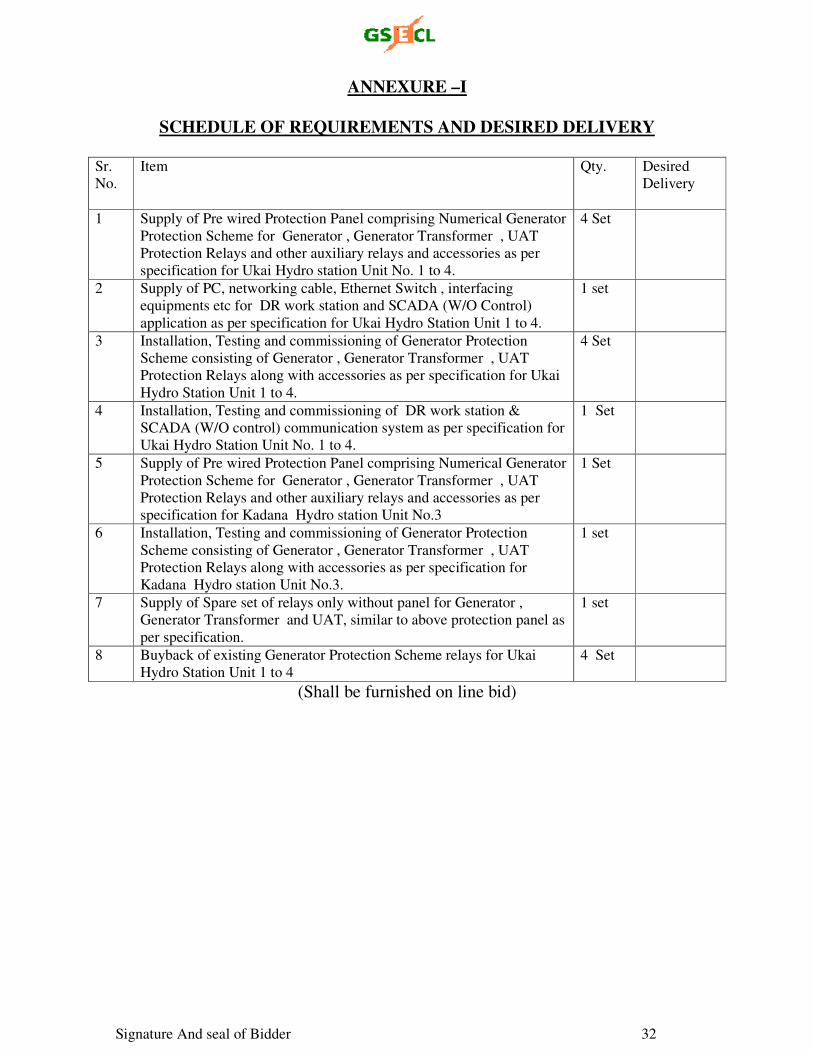
Signature And seal of Bidder 32
ANNEXURE –I
SCHEDULE OF REQUIREMENTS AND DESIRED DELIVERY
Sr.
No.
Item Qty. Desired
Delivery
1 Supply of Pre wired Protection Panel comprising Numerical Generator
Protection Scheme for Generator , Generator Transformer , UAT
Protection Relays and other auxiliary relays and accessories as per
specification for Ukai Hydro station Unit No. 1 to 4.
4 Set
2 Supply of PC, networking cable, Ethernet Switch , interfacing
equipments etc for DR work station and SCADA (W/O Control)
application as per specification for Ukai Hydro Station Unit 1 to 4.
1 set
3 Installation, Testing and commissioning of Generator Protection
Scheme consisting of Generator , Generator Transformer , UAT
Protection Relays along with accessories as per specification for Ukai
Hydro Station Unit 1 to 4.
4 Set
4 Installation, Testing and commissioning of DR work station &
SCADA (W/O control) communication system as per specification for
Ukai Hydro Station Unit No. 1 to 4.
1 Set
5 Supply of Pre wired Protection Panel comprising Numerical Generator
Protection Scheme for Generator , Generator Transformer , UAT
Protection Relays and other auxiliary relays and accessories as per
specification for Kadana Hydro station Unit No.3
1 Set
6 Installation, Testing and commissioning of Generator Protection
Scheme consisting of Generator , Generator Transformer , UAT
Protection Relays along with accessories as per specification for
Kadana Hydro station Unit No.3.
1 set
7 Supply of Spare set of relays only without panel for Generator ,
Generator Transformer and UAT, similar to above protection panel as
per specification.
1 set
8 Buyback of existing Generator Protection Scheme relays for Ukai
Hydro Station Unit 1 to 4
4 Set
(Shall be furnished on line bid)
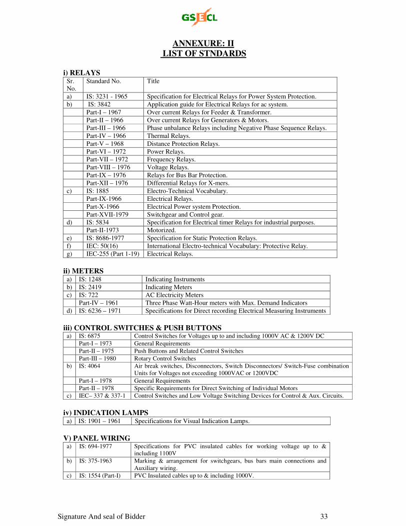
Signature And seal of Bidder 33
ANNEXURE: II LIST OF STNDARDS
i) RELAYS
Sr.
No.
Standard No. Title
a) IS: 3231 - 1965 Specification for Electrical Relays for Power System Protection.
b) IS: 3842 Application guide for Electrical Relays for ac system.
Part-I – 1967 Over current Relays for Feeder & Transformer.
Part-II – 1966 Over current Relays for Generators & Motors.
Part-III – 1966 Phase unbalance Relays including Negative Phase Sequence Relays.
Part-IV – 1966 Thermal Relays.
Part-V – 1968 Distance Protection Relays.
Part-VI – 1972 Power Relays.
Part-VII – 1972 Frequency Relays.
Part-VIII – 1976 Voltage Relays.
Part-IX – 1976 Relays for Bus Bar Protection.
Part-XII – 1976 Differential Relays for X-mers.
c) IS: 1885 Electro-Technical Vocabulary.
Part-IX-1966 Electrical Relays.
Part-X-1966 Electrical Power system Protection.
Part-XVII-1979 Switchgear and Control gear.
d) IS: 5834 Specification for Electrical timer Relays for industrial purposes.
Part-II-1973 Motorized.
e) IS: 8686-1977 Specification for Static Protection Relays.
f) IEC: 50(16) International Electro-technical Vocabulary: Protective Relay.
g) IEC-255 (Part 1-19) Electrical Relays.
ii) METERS a) IS: 1248 Indicating Instruments
b) IS: 2419 Indicating Meters
c) IS: 722 AC Electricity Meters
Part-IV – 1961 Three Phase Watt-Hour meters with Max. Demand Indicators
d) IS: 6236 – 1971 Specifications for Direct recording Electrical Measuring Instruments
iii) CONTROL SWITCHES & PUSH BUTTONS a) IS: 6875 Control Switches for Voltages up to and including 1000V AC & 1200V DC
Part-I – 1973 General Requirements
Part-II – 1975 Push Buttons and Related Control Switches
Part-III – 1980 Rotary Control Switches
b) IS: 4064 Air break switches, Disconnectors, Switch Disconnectors/ Switch-Fuse combination
Units for Voltages not exceeding 1000VAC or 1200VDC
Part-I – 1978 General Requirements
Part-II – 1978 Specific Requirements for Direct Switching of Individual Motors
c) IEC– 337 & 337-1 Control Switches and Low Voltage Switching Devices for Control & Aux. Circuits.
iv) INDICATION LAMPS a) IS: 1901 – 1961 Specifications for Visual Indication Lamps.
V) PANEL WIRING a) IS: 694-1977 Specifications for PVC insulated cables for working voltage up to &
including 1100V
b) IS: 375-1963 Marking & arrangement for switchgears, bus bars main connections and
Auxiliary wiring.
c) IS: 1554 (Part-I) PVC Insulated cables up to & including 1000V.
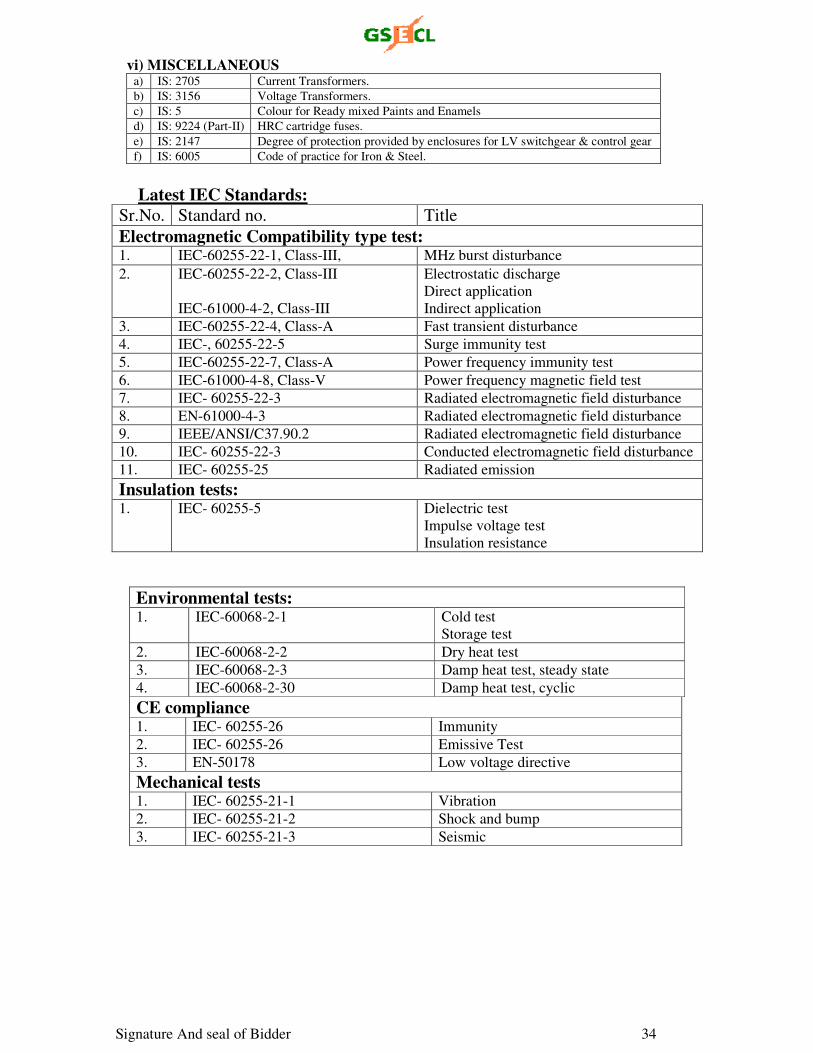
Signature And seal of Bidder 34
vi) MISCELLANEOUS a) IS: 2705 Current Transformers.
b) IS: 3156 Voltage Transformers.
c) IS: 5 Colour for Ready mixed Paints and Enamels
d) IS: 9224 (Part-II) HRC cartridge fuses.
e) IS: 2147 Degree of protection provided by enclosures for LV switchgear & control gear
f) IS: 6005 Code of practice for Iron & Steel.
Latest IEC Standards: Sr.No. Standard no. Title
Electromagnetic Compatibility type test: 1. IEC-60255-22-1, Class-III, MHz burst disturbance
2. IEC-60255-22-2, Class-III
IEC-61000-4-2, Class-III
Electrostatic discharge
Direct application
Indirect application
3. IEC-60255-22-4, Class-A Fast transient disturbance
4. IEC-, 60255-22-5 Surge immunity test
5. IEC-60255-22-7, Class-A Power frequency immunity test
6. IEC-61000-4-8, Class-V Power frequency magnetic field test
7. IEC- 60255-22-3 Radiated electromagnetic field disturbance
8. EN-61000-4-3 Radiated electromagnetic field disturbance
9. IEEE/ANSI/C37.90.2 Radiated electromagnetic field disturbance
10. IEC- 60255-22-3 Conducted electromagnetic field disturbance
11. IEC- 60255-25 Radiated emission
Insulation tests: 1. IEC- 60255-5 Dielectric test
Impulse voltage test
Insulation resistance
Environmental tests: 1. IEC-60068-2-1 Cold test
Storage test
2. IEC-60068-2-2 Dry heat test
3. IEC-60068-2-3 Damp heat test, steady state
4. IEC-60068-2-30 Damp heat test, cyclic
CE compliance 1. IEC- 60255-26 Immunity
2. IEC- 60255-26 Emissive Test
3. EN-50178 Low voltage directive
Mechanical tests 1. IEC- 60255-21-1 Vibration
2. IEC- 60255-21-2 Shock and bump
3. IEC- 60255-21-3 Seismic
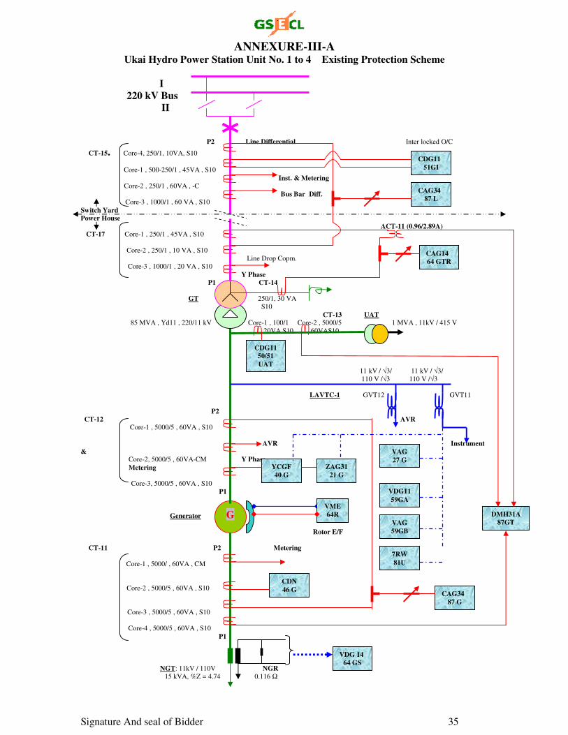
Signature And seal of Bidder 35
ANNEXURE-III-A Ukai Hydro Power Station Unit No. 1 to 4 Existing Protection Scheme
I
220 kV Bus II P2 Line Differential Inter locked O/C
CT-15. Core-4, 250/1, 10VA, S10 Core-1 , 500-250/1 , 45VA , S10
Inst. & Metering Core-2 , 250/1 , 60VA , -C
Bus Bar Diff. Core-3 , 1000/1 , 60 VA , S10
Switch Yard Power House
ACT-11 (0.96/2.89A) CT-17 Core-1 , 250/1 , 45VA , S10
Core-2 , 250/1 , 10 VA , S10 Line Drop Copm.
Core-3 , 1000/1 , 20 VA , S10 Y Phase P1 CT-14
GT 250/1, 30 VA
S10
CT-13 UAT 85 MVA , Yd11 , 220/11 kV Core-1 , 100/1 Core-2 , 5000/5 1 MVA , 11kV / 415 V
20VA S10 60VAS10
11 kV / √3/ 11 kV / √3/ 110 V /√3 110 V /√3
LAVTC-1 GVT12 GVT11
P2
CT-12 AVR Core-1 , 5000/5 , 60VA , S10
AVR Instrument & Core-2, 5000/5 , 60VA-CM Y Phase
Metering
Core-3, 5000/5 , 60VA , S10
P1
Generator
Rotor E/F
CT-11 P2 Metering
Core-1 , 5000/ , 60VA , CM
Core-2 , 5000/5 , 60VA , S10
Core-3 , 5000/5 , 60VA , S10
Core-4 , 5000/5 , 60VA , S10
P1
NGT: 11kV / 110V NGR 15 kVA, %Z = 4.74 0.116 Ω
G
VME64R DMH31A
87GT
VDG 14 64 GS
CAG34 87 G
CDN
46 G
YCGF 40 G
ZAG31 21 G
VDG11
59GA
VAG
59GB
VAG
27 G
CDG11 50/51
UAT
CAG14 64 GTR
CAG34 87 L
CDG11 51GI
7RW
81U
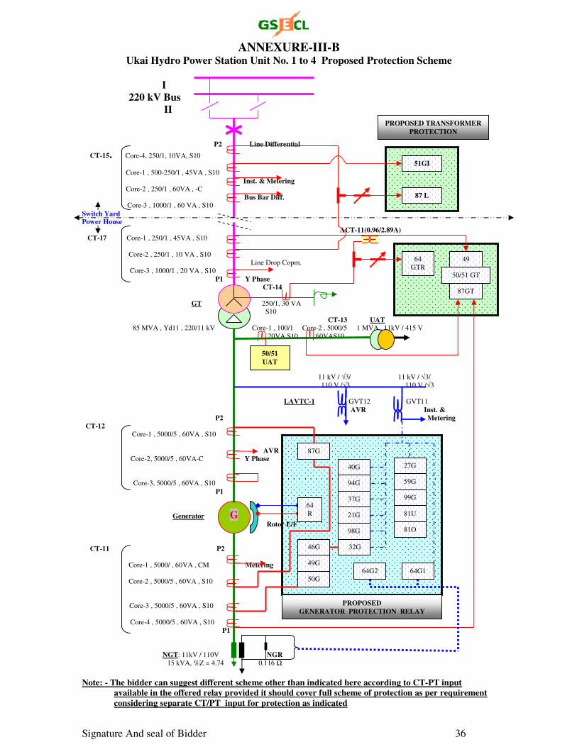
Signature And seal of Bidder 36
ANNEXURE-III-B Ukai Hydro Power Station Unit No. 1 to 4 Proposed Protection Scheme
I
220 kV Bus II P2 Line Differential
CT-15. Core-4, 250/1, 10VA, S10 Core-1 , 500-250/1 , 45VA , S10
Inst. & Metering Core-2 , 250/1 , 60VA , -C
Bus Bar Diff. Core-3 , 1000/1 , 60 VA , S10
Switch Yard Power House
ACT-11(0.96/2.89A) CT-17 Core-1 , 250/1 , 45VA , S10
Core-2 , 250/1 , 10 VA , S10 Line Drop Copm.
Core-3 , 1000/1 , 20 VA , S10 P1 Y Phase CT-14
GT 250/1, 30 VA
S10
CT-13 UAT 85 MVA , Yd11 , 220/11 kV Core-1 , 100/1 Core-2 , 5000/5 1 MVA , 11kV / 415 V
20VA S10 60VAS10
11 kV / √3/ 11 kV / √3/ 110 V /√3 110 V /√3
LAVTC-1 GVT12 GVT11
AVR Inst. & P2 Metering
CT-12 Core-1 , 5000/5 , 60VA , S10
AVR Core-2, 5000/5 , 60VA-C Y Phase
Core-3, 5000/5 , 60VA , S10
P1
Generator Rotor E/F
CT-11 P2
Core-1 , 5000/ , 60VA , CM Metering
Core-2 , 5000/5 , 60VA , S10
Core-3 , 5000/5 , 60VA , S10
Core-4 , 5000/5 , 60VA , S10
P1
NGT: 11kV / 110V NGR 15 kVA, %Z = 4.74 0.116 Ω
Note: - The bidder can suggest different scheme other than indicated here according to CT-PT input
available in the offered relay provided it should cover full scheme of protection as per requirement considering separate CT/PT input for protection as indicated
G
50/51 UAT
87 L
51GI
87G
40G
37G
21G
98G
32G 46G
49G
50G
59G
99G
81U
81O
64G1
64
R
27G
64G2
94G
PROPOSED GENERATOR PROTECTION RELAY
87GT
64
GTR 50/51 GT
49
PROPOSED TRANSFORMER
PROTECTION
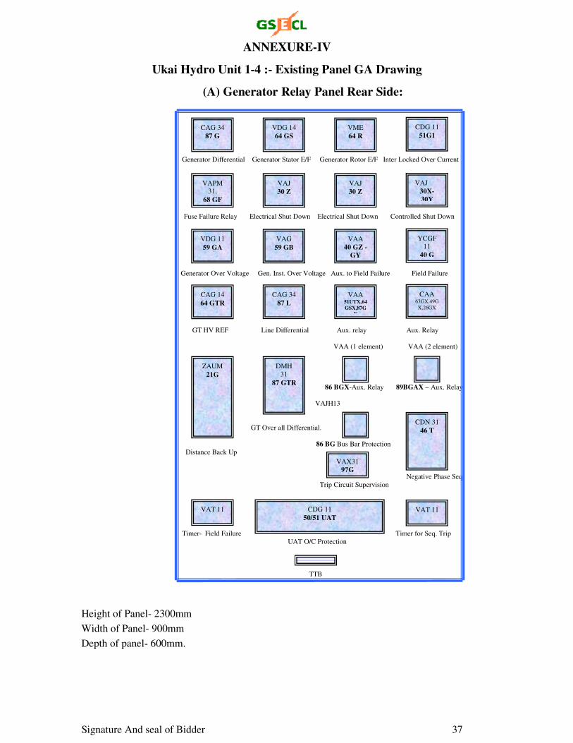
Signature And seal of Bidder 37
ANNEXURE-IV
Ukai Hydro Unit 1-4 :- Existing Panel GA Drawing
(A) Generator Relay Panel Rear Side:
Generator Differential Generator Stator E/F Generator Rotor E/F Inter Locked Over Current
Fuse Failure Relay Electrical Shut Down Electrical Shut Down Controlled Shut Down
Generator Over Voltage Gen. Inst. Over Voltage Aux. to Field Failure Field Failure
GT HV REF Line Differential Aux. relay Aux. Relay
VAA (1 element) VAA (2 element)
86 BGX-Aux. Relay 89BGAX – Aux. Relay
VAJH13
GT Over all Differential.
86 BG Bus Bar Protection
Distance Back Up
Negative Phase Seq.
Trip Circuit Supervision
Timer- Field Failure Timer for Seq. Trip
UAT O/C Protection
TTB
Height of Panel- 2300mm
Width of Panel- 900mm
Depth of panel- 600mm.
CAG 34
87 G
VDG 14
64 GS
VME
64 R
CDG 11
51G1
VAPM 31,
68 GF
VAJ
30 Z
VAJ
30 Z
VAJ
30X-30Y
VDG 11
59 GA
VAG
59 GB
VAA
40 GZ -GY
YCGF 11
40 G
CAG 14
64 GTR
CAG 34
87 L
VAA 51UTX,64GSX,87G
X
CAA 63GX,49G
X,26GX
ZAUM
21G
DMH
31
87 GTR
VAX31
97G
CDN 31
46 T
VAT 11 CDG 11
50/51 UAT VAT 11
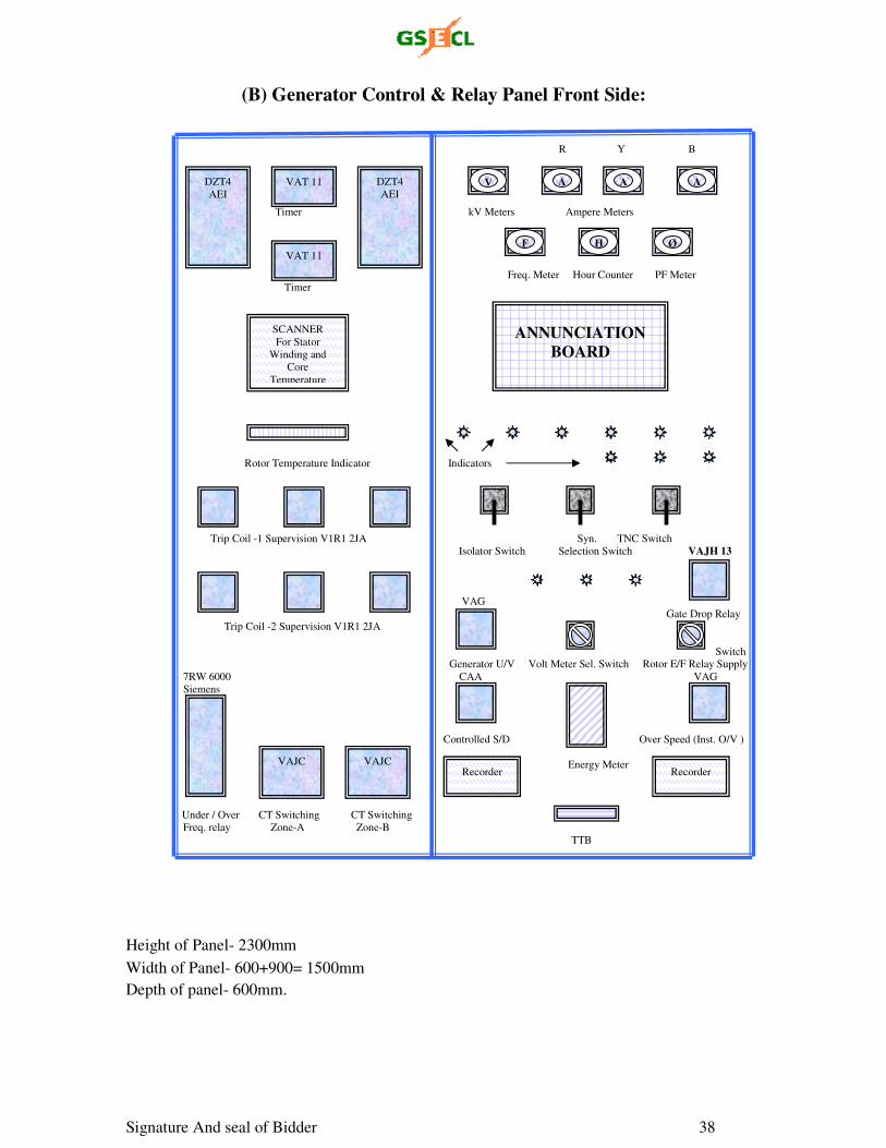
Signature And seal of Bidder 38
(B) Generator Control & Relay Panel Front Side:
R Y B
Timer kV Meters Ampere Meters
Freq. Meter Hour Counter PF Meter
Timer
Rotor Temperature Indicator Indicators
Trip Coil -1 Supervision V1R1 2JA Syn. TNC Switch
Isolator Switch Selection Switch VAJH 13
VAG
Gate Drop Relay
Trip Coil -2 Supervision V1R1 2JA
Switch Generator U/V Volt Meter Sel. Switch Rotor E/F Relay Supply
7RW 6000 CAA VAG
Siemens
Controlled S/D Over Speed (Inst. O/V )
Energy Meter
Under / Over CT Switching CT Switching
Freq. relay Zone-A Zone-B
TTB
Height of Panel- 2300mm
Width of Panel- 600+900= 1500mm
Depth of panel- 600mm.
VAT 11
VAT 11
DZT4
AEI
DZT4
AEI A
SCANNER
For Stator
Winding and
Core
Temperature
VAJC VAJC
ANNUNCIATION BOARD
Recorder
F H Ø
V A A
Recorder

Signature And seal of Bidder 39
ANNEXURE-V
Ukai Hydro Power Station Unit No. 1 to 4 CT , PT and Relay Details
(A) Details for Current Transformer:
(i) Generator Neutral side CT details: CT-11
CORE MAKE CTR VA Acc. Class
Secondary
Resistance PURPOSE
1 Heavy
Elect. Ltd.
Bhopal
Standard:
BS 3938
5000/5A 60 CM 1.53 Instrument & Metering
2 5000/5A 60 S-10 1.53 46G (Negative Phase Sequence )
3 5000/5A 60 S-10 1.53 87G (Generator Differential)
4 5000/5A 60 S-10 1.7 87GT(Over all differential)
(ii) Generator Phase side CT details: CT-12
CORE MAKE CTR VA Acc. Class
Secondary
Resistance PURPOSE
1 Heavy
Elect.
Ltd.
Bhopal.
Standard:
BS 3938
5000/5A 60 C/S10 1.53 87G (Generator Differential)
2 5000/5A 60 C 1.53 AVR ( Y Phase Only)
3 5000/5A 60 S-10 1.53 40G (Field Failure)
21G ( Dist. Back Up)
(iii) 220 kV Side CT Details:
(a) Generator Transformer 220 kV Power House side CT (Unit No 1):- CT-17
CORE CTR VA Acc. Class PURPOSE Remark
1 250/1 A 45 10 P10 87GT (Over all differential)
64GTR(GT Restricted E/F )
ACT-11
0.96/2.89 A
2 250/1 A 10 10 P10 87L (Line differential)
(b) Generator Transformer Neutral Side CT details (Unit No.1):- CT-14
CORE CTR VA Acc. Class PURPOSE Remark
GT
Bushing CT 250/1 A 30 10 P10 64GTR(GT Restricted E/F )
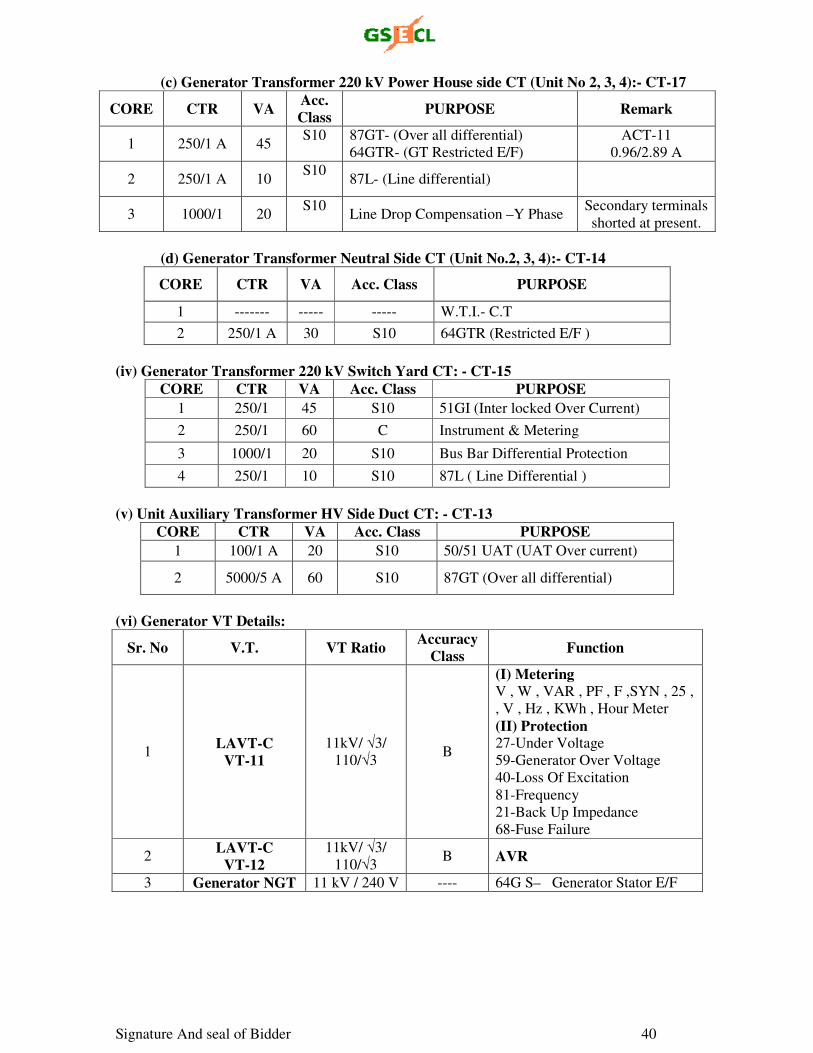
Signature And seal of Bidder 40
(c) Generator Transformer 220 kV Power House side CT (Unit No 2, 3, 4):- CT-17
CORE CTR VA Acc. Class
PURPOSE Remark
1 250/1 A 45 S10
87GT- (Over all differential)
64GTR- (GT Restricted E/F)
ACT-11
0.96/2.89 A
2 250/1 A 10 S10
87L- (Line differential)
3 1000/1 20 S10
Line Drop Compensation –Y Phase
Secondary terminals
shorted at present.
(d) Generator Transformer Neutral Side CT (Unit No.2, 3, 4):- CT-14
CORE CTR VA Acc. Class PURPOSE
1 ------- ----- ----- W.T.I.- C.T
2 250/1 A 30 S10 64GTR (Restricted E/F )
(iv) Generator Transformer 220 kV Switch Yard CT: - CT-15
CORE CTR VA Acc. Class PURPOSE
1 250/1 45 S10 51GI (Inter locked Over Current)
2 250/1 60 C Instrument & Metering
3 1000/1 20 S10 Bus Bar Differential Protection
4 250/1 10 S10 87L ( Line Differential )
(v) Unit Auxiliary Transformer HV Side Duct CT: - CT-13
CORE CTR VA Acc. Class PURPOSE
1 100/1 A 20 S10 50/51 UAT (UAT Over current)
2 5000/5 A 60 S10 87GT (Over all differential)
(vi) Generator VT Details:
Sr. No V.T. VT Ratio Accuracy
Class Function
1 LAVT-C
VT-11
11kV/ √3/
110/√3 B
(I) Metering V , W , VAR , PF , F ,SYN , 25 ,
, V , Hz , KWh , Hour Meter
(II) Protection 27-Under Voltage
59-Generator Over Voltage
40-Loss Of Excitation
81-Frequency
21-Back Up Impedance
68-Fuse Failure
2 LAVT-C
VT-12
11kV/ √3/
110/√3 B AVR
3 Generator NGT 11 kV / 240 V ---- 64G S– Generator Stator E/F
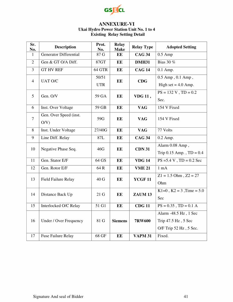
Signature And seal of Bidder 41
ANNEXURE-VI Ukai Hydro Power Station Unit No. 1 to 4
Existing Relay Setting Detail
Sr. No.
Description Prot. No.
Relay Make
Relay Type Adopted Setting
1 Generator Differential 87 G EE CAG 34 0.5 Amp
2 Gen & GT O/A Diff. 87GT EE DMH31 Bias 30 %
3 GT HV REF 64 GTR EE CAG 14 0.1 Amp.
4 UAT O/C 50/51
UTR EE CDG
0.5 Amp , 0.1 Amp ,
High set = 4.0 Amp.
5 Gen. O/V 59 GA EE VDG 11 , PS = 132 V , TD = 0.2
Sec.
6 Inst. Over Voltage 59 GB EE VAG 154 V Fixed
7 Gen. Over Speed (inst.
O/V) 59G EE VAG 154 V Fixed
8 Inst. Under Voltage 27/40G EE VAG 77 Volts
9 Line Diff. Relay 87L EE CAG 34 0.2 Amp.
10 Negative Phase Seq. 46G EE CDN 31 Alarm 0.08 Amp ,
Trip 0.15 Amp. , TD = 0.4
11 Gen. Stator E/F 64 GS EE VDG 14 PS =5.4 V , TD = 0.2 Sec
12 Gen. Rotor E/F 64 R EE VME 21 1 mA
13 Field Failure Relay 40 G EE YCGF 11 Z1 = 1.5 Ohm , Z2 = 27
Ohm
14 Distance Back Up 21 G EE ZAUM 13 K1=0 , K2 = 3 ,Time = 5.0
Sec
15 Interlocked O/C Relay 51 G1 EE CDG 11 PS = 0.35 , TD = 0.1 A
16 Under / Over Frequency 81 G Siemens 7RW600
Alarm -48.5 Hz , 1 Sec
Trip 47.5 Hz , 5 Sec
O/F Trip 52 Hz , 5 Sec.
17 Fuse Failure Relay 68 GF EE VAPM 31 Fixed.
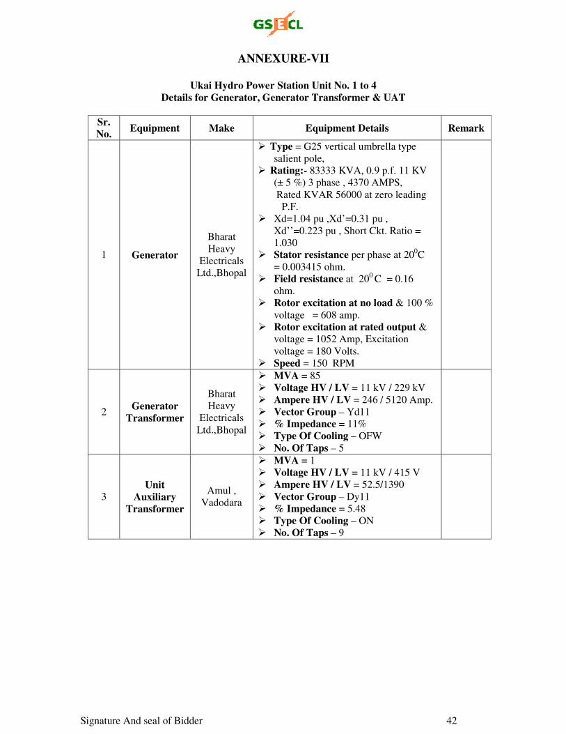
Signature And seal of Bidder 42
ANNEXURE-VII
Ukai Hydro Power Station Unit No. 1 to 4 Details for Generator, Generator Transformer & UAT
Sr. No.
Equipment Make Equipment Details Remark
1 Generator
Bharat
Heavy
Electricals
Ltd.,Bhopal
Type = G25 vertical umbrella type
salient pole,
Rating:- 83333 KVA, 0.9 p.f. 11 KV
(± 5 %) 3 phase , 4370 AMPS,
Rated KVAR 56000 at zero leading
P.F.
Xd=1.04 pu ,Xd’=0.31 pu ,
Xd’’=0.223 pu , Short Ckt. Ratio =
1.030
Stator resistance per phase at 200C
= 0.003415 ohm.
Field resistance at 200 C = 0.16
ohm.
Rotor excitation at no load & 100 %
voltage = 608 amp.
Rotor excitation at rated output &
voltage = 1052 Amp, Excitation
voltage = 180 Volts.
Speed = 150 RPM
2 Generator
Transformer
Bharat
Heavy
Electricals
Ltd.,Bhopal
MVA = 85
Voltage HV / LV = 11 kV / 229 kV
Ampere HV / LV = 246 / 5120 Amp.
Vector Group – Yd11
% Impedance = 11%
Type Of Cooling – OFW
No. Of Taps – 5
3 Unit
Auxiliary Transformer
Amul ,
Vadodara
MVA = 1
Voltage HV / LV = 11 kV / 415 V
Ampere HV / LV = 52.5/1390
Vector Group – Dy11
% Impedance = 5.48
Type Of Cooling – ON
No. Of Taps – 9
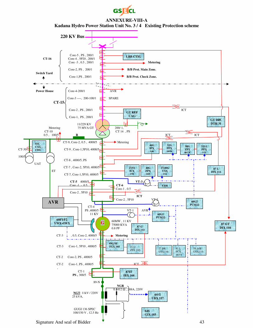
Signature And seal of Bidder 43
ANNEXURE-VIII-A Kadana Hydro Power Station Unit No. 3 / 4 Existing Protection scheme
220 KV Bus
Core-5 , PS , 200/1 CT-16 Core-4 , 5P20 , 200/1
Core -3 , 0.5 , 200/1 Metering
Core-2, PS , 200/1 B/B Prot. Main Zone. Switch Yard Core-1,PS , 200/1 B/B Prot. Check Zone.
Power House Core-4-200/1 AVR
Core-3 ----, 200-100/1 SPARE
CT-15 Core-2 , PS , 200/1 ICT
Core-1, PS , 200/1 11/229 KV
Metering 75 MVA GT 200/ 1,
CT-10 CT 14 , PS 0.5 , 100/5 R ICT ICT
CT-9, Core-2, 0.5 , 4000/5 Metering
CT-30 CT-9 , Core-1,5P10, 4000/5
100/5 CT-8 , 4000/5, PS
UAT CT-7 , Core-2, 5P10, 4000/5
ET
CT-7, Core-1,5P10, 4000/5
CT-5 4000/5 VT-3
Core -1 - 0.5 CT-6 Core-1 , 0.5
Core-2 , 5P10 ICT Core-2 , 5P10 VT-2
CT-4
PS ,4000/5 VT-1 AVR
11 KV
60MW , 11 KV
75000 KVA 0.8 PF
CT-3 , 0.5, Core-2, 4000/5 Metering
CT-3 Core-1, 5P10 , 4000/5
CT-2 Core-2, PS , 4000/5
CT-2 Core-1, PS , 4000/5 ICT
,
CT-1 PS , 300/5
89-N
NGR 0.4412 Ω , 288A, 220V
NGT: 11kV / 220V
25 kVA,
GUGI 136 SPEC 100/150 V , 12.5 Hz
G
60F1/F2 YWX+IWX 87 GT
DIX 110
64 G UBX 117
87 G
DIX 111
49G/M TGX 105
GT Diff. DTH 31
64S
GIX 103
87IT IBX 164
21 G
ZSX 102 27 BR
USX116
81 L
FCX
103 b
59 A/B
USX115
60G1 PUM22
60G2
PUM22
EHR
40G ZPX 103
27/40G USX 116
27/51 IUX 159
32G PPX 105b
98G ZPT RGX
46G IPX 146
32G1 PPX 111
87 L DIX 111
AVR
O/C CAG -CDG
GT REF CAG
LBB CTIG
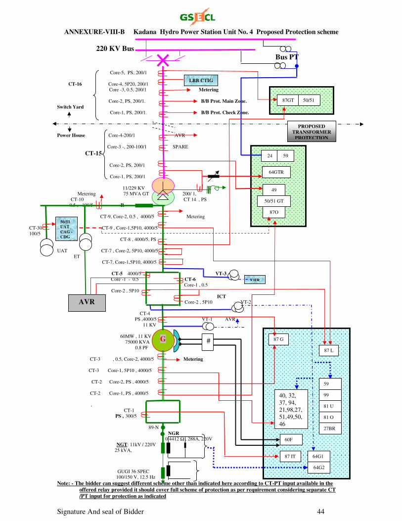
Signature And seal of Bidder 44
ANNEXURE-VIII-B Kadana Hydro Power Station Unit No. 4 Proposed Protection scheme
220 KV Bus
Bus PT Core-5, PS , 200/1
CT-16 Core-4, 5P20, 200/1
Core -3, 0.5, 200/1 Metering
Core-2, PS, 200/1. B/B Prot. Main Zone. Switch Yard Core-1, PS, 200/1. B/B Prot. Check Zone.
Power House Core-4-200/1 AVR
Core-3 -, 200-100/1 SPARE
CT-15 Core-2, PS, 200/1
Core-1, PS, 200/1 11/229 KV
Metering 75 MVA GT 200/ 1,
CT-10 CT 14 , PS
0.5 , 100/5 R
CT-9, Core-2, 0.5 , 4000/5 Metering
CT-30 CT-9 , Core-1,5P10, 4000/5
100/5 CT-8 , 4000/5, PS
UAT CT-7 , Core-2, 5P10, 4000/5
ET
CT-7, Core-1,5P10, 4000/5
CT-5 4000/5 VT-3
Core -1 - 0.5 CT-6
Core-1 , 0.5
Core-2 , 5P10 ICT Core-2 , 5P10 VT-2
CT-4
PS ,4000/5 VT-1 AVR
11 KV
60MW , 11 KV
75000 KVA
0.8 PF
CT-3 , 0.5, Core-2, 4000/5 Metering
CT-3 Core-1, 5P10 , 4000/5 CT-2 Core-2, PS , 4000/5
CT-2 Core-1, PS , 4000/5
,
CT-1 PS , 300/5
89-N
NGR 0.4412 Ω , 288A, 220V
NGT: 11kV / 220V
25 kVA,
GUGI 36 SPEC 100/150 V, 12.5 Hz Note: - The bidder can suggest different scheme other than indicated here according to CT-PT input available in the
offered relay provided it should cover full scheme of protection as per requirement considering separate CT /PT input for protection as indicated
G
EHR
AVR
50/51 UAT CAG -CDG
LBB CTIG
87 G
59
99
81 U
81 O
64G2
64G1 87 IT
87 L
#
60F
27BR
87O
64GTR
50/51 GT
24
49
59
87GT 50/51
PROPOSED TRANSFORMER
PROTECTION
40, 32,
37, 94,
21,98,27,
51,49,50,
46
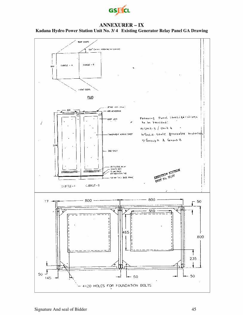
Signature And seal of Bidder 45
ANNEXURER – IX Kadana Hydro Power Station Unit No. 3/ 4 Existing Generator Relay Panel GA Drawing
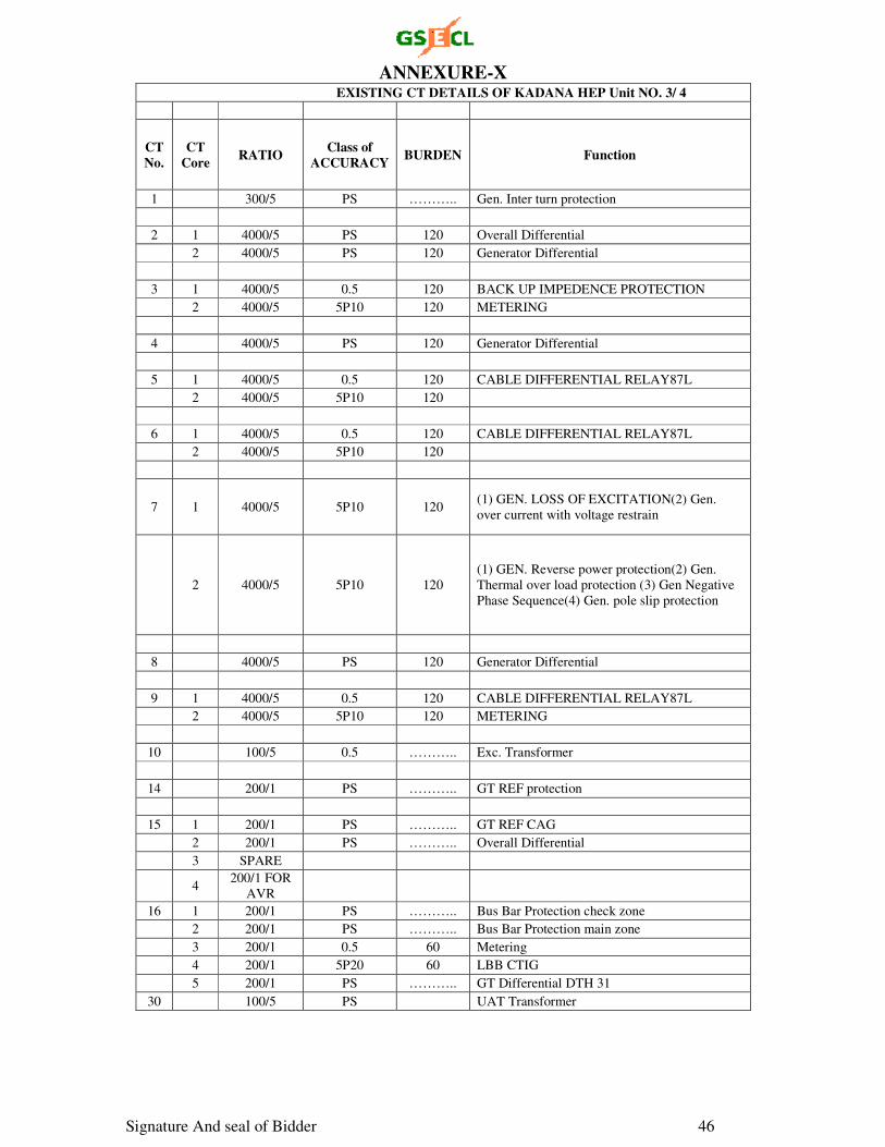
Signature And seal of Bidder 46
ANNEXURE-X EXISTING CT DETAILS OF KADANA HEP Unit NO. 3/ 4
CT No.
CT Core
RATIO Class of
ACCURACY BURDEN Function
1 300/5 PS ……….. Gen. Inter turn protection
2 1 4000/5 PS 120 Overall Differential
2 4000/5 PS 120 Generator Differential
3 1 4000/5 0.5 120 BACK UP IMPEDENCE PROTECTION
2 4000/5 5P10 120 METERING
4 4000/5 PS 120 Generator Differential
5 1 4000/5 0.5 120 CABLE DIFFERENTIAL RELAY87L
2 4000/5 5P10 120
6 1 4000/5 0.5 120 CABLE DIFFERENTIAL RELAY87L
2 4000/5 5P10 120
7 1 4000/5 5P10 120 (1) GEN. LOSS OF EXCITATION(2) Gen.
over current with voltage restrain
2 4000/5 5P10 120
(1) GEN. Reverse power protection(2) Gen.
Thermal over load protection (3) Gen Negative
Phase Sequence(4) Gen. pole slip protection
8 4000/5 PS 120 Generator Differential
9 1 4000/5 0.5 120 CABLE DIFFERENTIAL RELAY87L
2 4000/5 5P10 120 METERING
10 100/5 0.5 ……….. Exc. Transformer
14 200/1 PS ……….. GT REF protection
15 1 200/1 PS ……….. GT REF CAG
2 200/1 PS ……….. Overall Differential
3 SPARE
4 200/1 FOR
AVR
16 1 200/1 PS ……….. Bus Bar Protection check zone
2 200/1 PS ……….. Bus Bar Protection main zone
3 200/1 0.5 60 Metering
4 200/1 5P20 60 LBB CTIG
5 200/1 PS ……….. GT Differential DTH 31
30 100/5 PS UAT Transformer
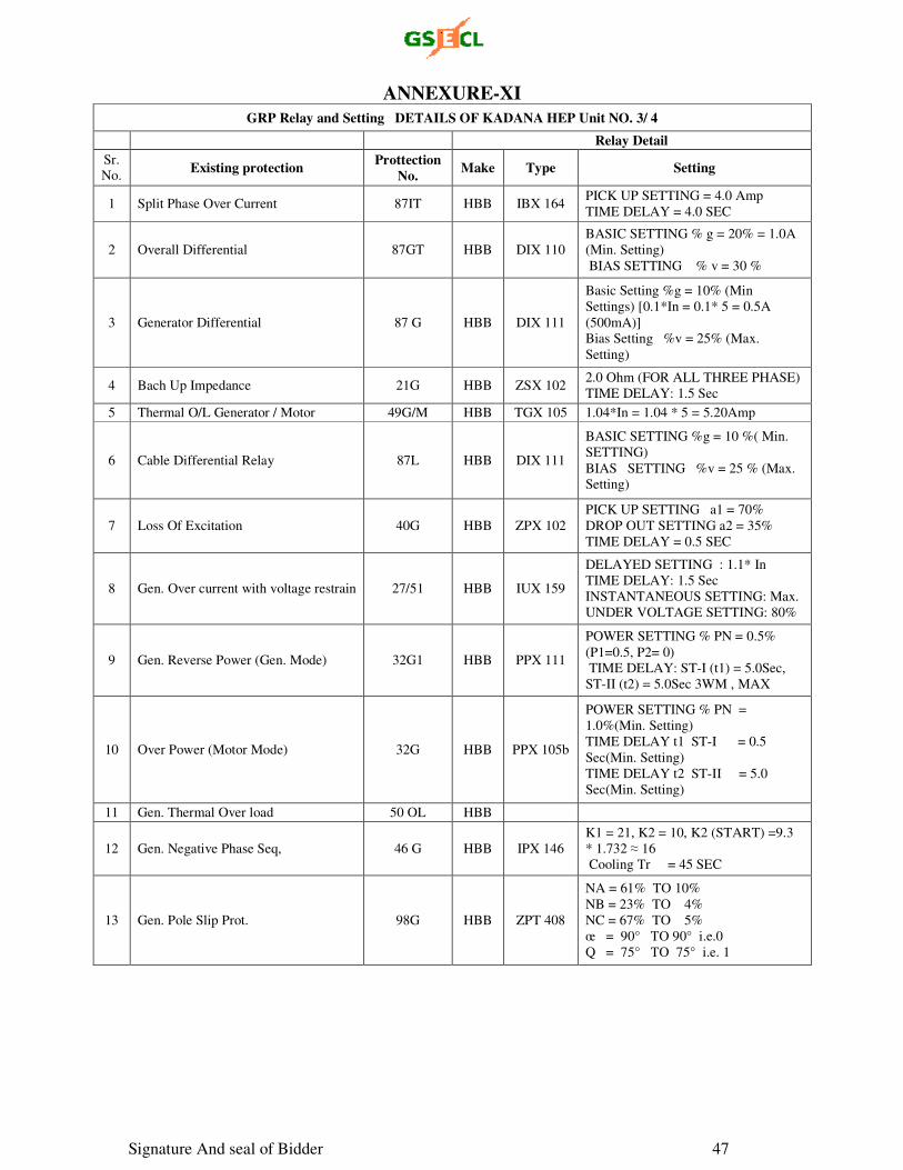
Signature And seal of Bidder 47
ANNEXURE-XI
GRP Relay and Setting DETAILS OF KADANA HEP Unit NO. 3/ 4
Relay Detail
Sr.
No. Existing protection
Prottection No.
Make Type Setting
1 Split Phase Over Current 87IT HBB IBX 164 PICK UP SETTING = 4.0 Amp
TIME DELAY = 4.0 SEC
2 Overall Differential 87GT HBB DIX 110
BASIC SETTING % g = 20% = 1.0A
(Min. Setting)
BIAS SETTING % v = 30 %
3 Generator Differential 87 G HBB DIX 111
Basic Setting %g = 10% (Min
Settings) [0.1*In = 0.1* 5 = 0.5A
(500mA)]
Bias Setting %v = 25% (Max.
Setting)
4 Bach Up Impedance 21G HBB ZSX 102 2.0 Ohm (FOR ALL THREE PHASE)
TIME DELAY: 1.5 Sec
5 Thermal O/L Generator / Motor 49G/M HBB TGX 105 1.04*In = 1.04 * 5 = 5.20Amp
6 Cable Differential Relay 87L HBB DIX 111
BASIC SETTING %g = 10 %( Min.
SETTING)
BIAS SETTING %v = 25 % (Max.
Setting)
7 Loss Of Excitation 40G HBB ZPX 102
PICK UP SETTING a1 = 70%
DROP OUT SETTING a2 = 35%
TIME DELAY = 0.5 SEC
8 Gen. Over current with voltage restrain 27/51 HBB IUX 159
DELAYED SETTING : 1.1* In
TIME DELAY: 1.5 Sec
INSTANTANEOUS SETTING: Max.
UNDER VOLTAGE SETTING: 80%
9 Gen. Reverse Power (Gen. Mode) 32G1 HBB PPX 111
POWER SETTING % PN = 0.5%
(P1=0.5, P2= 0)
TIME DELAY: ST-I (t1) = 5.0Sec,
ST-II (t2) = 5.0Sec 3WM , MAX
10 Over Power (Motor Mode) 32G HBB PPX 105b
POWER SETTING % PN =
1.0%(Min. Setting)
TIME DELAY t1 ST-I = 0.5
Sec(Min. Setting)
TIME DELAY t2 ST-II = 5.0
Sec(Min. Setting)
11 Gen. Thermal Over load 50 OL HBB
12 Gen. Negative Phase Seq, 46 G HBB IPX 146
K1 = 21, K2 = 10, K2 (START) =9.3
* 1.732 ≈ 16
Cooling Tr = 45 SEC
13 Gen. Pole Slip Prot. 98G HBB ZPT 408
NA = 61% TO 10%
NB = 23% TO 4%
NC = 67% TO 5%
œ = 90° TO 90° i.e.0
Q = 75° TO 75° i.e. 1
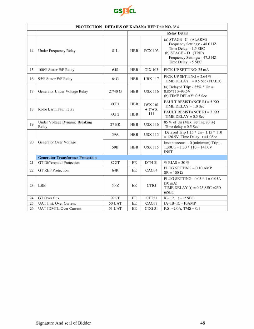
Signature And seal of Bidder 48
PROTECTION DETAILS OF KADANA HEP Unit NO. 3/ 4
Relay Detail
14 Under Frequency Relay 81L HBB FCX 103
(a) STAGE –C (ALARM)
Frequency Settings: - 48.0 HZ
Time Delay: - 1.5 SEC
(b) STAGE – D (TRIP)
Frequency Settings: - 47.5 HZ
Time Delay: - 5 SEC
15 100% Stator E/F Relay 64S HBB GIX 103 PICK UP SETTING: 25 mA
16 95% Stator E/F Relay 64G HBB UBX 117 PICK UP SETTING = 2.64 %
TIME DELAY = 0.5 Sec (FIXED)
17 Generator Under Voltage Relay 27/40 G HBB USX 116
(a) Delayed Trip: - 85% * Un =
0.85*110=93.5V
(b) TIME DELAY: 0.5 Sec
18 Rotor Earth Fault relay
60F1 HBB IWX 161
+ YWX
111
FAULT RESISTANCE Rf = 5 KΩ
TIME DELAY = 1.0 Sec
60F2 HBB FAULT RESISTANCE Rf = 3 KΩ
TIME DELAY = 0.5 Sec
19 Under Voltage Dynamic Breaking
Relay 27 BR HBB USX 116
85 % of Un (Max. Setting 80 %)
Time delay = 0.5 Sec
20 Generator Over Voltage
59A HBB USX 115 Delayed Trip 1.15 * Un= 1.15 * 110
= 126.5V, Time Delay t =1.0Sec
59B HBB USX 115
Instantaneous: - 0 (minimum) Trip: -
1.30Un = 1.30 * 110 = 143.0V
INST.
Generator Transformer Protection
21 GT Differential Protection 87GT EE DTH 31 % BIAS = 30 %
22 GT REF Protection 64R EE CAG34 PLUG SETTING = 0.10 AMP
SR = 100 Ω
23 LBB 50 Z EE CTIG
PLUG SETTING: 0.05 * 1 = 0.05A
(50 mA)
TIME DELAY (t) = 0.25 SEC =250
mSEC
24 GT Over flux 99GT EE GTT21 K=1.2 t =12 SEC
25 UAT Inst. Over Current 50 UAT EE CAG37 IA=IB=IC =10AMP
26 UAT IDMTL Over Current 51 UAT EE CDG 31 P.S. =2.0A, TMS = 0.1
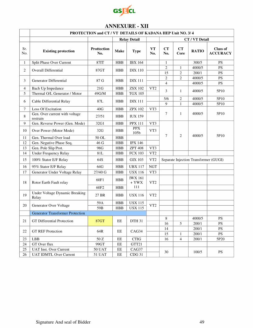
Signature And seal of Bidder 49
ANNEXURE - XII
PROTECTION and CT / VT DETAILS OF KADANA HEP Unit NO. 3/ 4
Relay Detail CT / VT Detail
Sr.
No. Existing protection
Prottection No.
Make Type VT No.
CT No.
CT Core
RATIO Class of
ACCURACY
1 Split Phase Over Current 87IT HBB IBX 164 1 300/5 PS
2 Overall Differential 87GT HBB DIX 110 2 1 4000/5 PS
15 2 200/1 PS
3 Generator Differential 87 G HBB DIX 111 2 2 4000/5 PS
4 4000/5 PS
4 Bach Up Impedance 21G HBB ZSX 102 VT2 3 1 4000/5 5P10
5 Thermal O/L Generator / Motor 49G/M HBB TGX 105
6 Cable Differential Relay 87L HBB DIX 111 5/6 2 4000/5 5P10
9 1 4000/5 5P10
7 Loss Of Excitation 40G HBB ZPX 102 VT3
7 1 4000/5 5P10 8
Gen. Over current with voltage
restrain 27/51 HBB IUX 159
9 Gen. Reverse Power (Gen. Mode) 32G1 HBB PPX 111 VT3
7 2 4000/5 5P10
10 Over Power (Motor Mode) 32G HBB PPX
105b VT3
11 Gen. Thermal Over load 50 OL HBB
12 Gen. Negative Phase Seq, 46 G HBB IPX 146
13 Gen. Pole Slip Prot. 98G HBB ZPT 408 VT3
14 Under Frequency Relay 81L HBB FCX 103 VT2
15 100% Stator E/F Relay 64S HBB GIX 103 VT2 Separate Injection Transformer (GUGI)
16 95% Stator E/F Relay 64G HBB UBX 117 NGT
17 Generator Under Voltage Relay 27/40 G HBB USX 116 VT3
18 Rotor Earth Fault relay 60F1 HBB
IWX 161
+ YWX
111
VT2
60F2 HBB
19 Under Voltage Dynamic Breaking
Relay 27 BR HBB USX 116 VT2
20 Generator Over Voltage 59A HBB USX 115
VT2
59B HBB USX 115
Generator Transformer Protection
21 GT Differential Protection 87GT EE DTH 31 8 4000/5 PS
16 5 200/1 PS
22 GT REF Protection 64R EE CAG34 14 200/1 PS
15 1 200/1 PS
23 LBB 50 Z EE CTIG 16 4 200/1 5P20
24 GT Over flux 99GT EE GTT21
25 UAT Inst. Over Current 50 UAT EE CAG37 30 100/5 PS
26 UAT IDMTL Over Current 51 UAT EE CDG 31
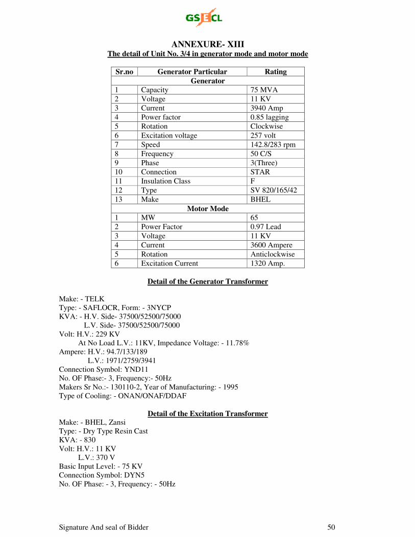
Signature And seal of Bidder 50
ANNEXURE- XIII
The detail of Unit No. 3/4 in generator mode and motor mode
Sr.no Generator Particular Rating
Generator 1 Capacity 75 MVA
2 Voltage 11 KV
3 Current 3940 Amp
4 Power factor 0.85 lagging
5 Rotation Clockwise
6 Excitation voltage 257 volt
7 Speed 142.8/283 rpm
8 Frequency 50 C/S
9 Phase 3(Three)
10 Connection STAR
11 Insulation Class F
12 Type SV 820/165/42
13 Make BHEL
Motor Mode 1 MW 65
2 Power Factor 0.97 Lead
3 Voltage 11 KV
4 Current 3600 Ampere
5 Rotation Anticlockwise
6 Excitation Current 1320 Amp.
Detail of the Generator Transformer
Make: - TELK
Type: - SAFLOCR, Form: - 3NYCP
KVA: - H.V. Side- 37500/52500/75000
L.V. Side- 37500/52500/75000
Volt: H.V.: 229 KV
At No Load L.V.: 11KV, Impedance Voltage: - 11.78%
Ampere: H.V.: 94.7/133/189
L.V.: 1971/2759/3941
Connection Symbol: YND11
No. OF Phase:- 3, Frequency:- 50Hz
Makers Sr No.:- 130110-2, Year of Manufacturing: - 1995
Type of Cooling: - ONAN/ONAF/DDAF
Detail of the Excitation Transformer
Make: - BHEL, Zansi
Type: - Dry Type Resin Cast
KVA: - 830
Volt: H.V.: 11 KV
L.V.: 370 V
Basic Input Level: - 75 KV
Connection Symbol: DYN5
No. OF Phase: - 3, Frequency: - 50Hz
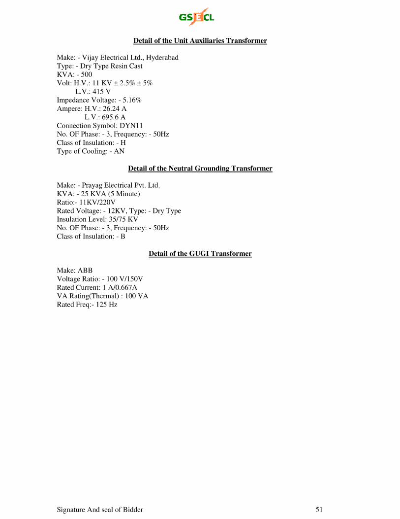
Signature And seal of Bidder 51
Detail of the Unit Auxiliaries Transformer
Make: - Vijay Electrical Ltd., Hyderabad
Type: - Dry Type Resin Cast
KVA: - 500
Volt: H.V.: 11 KV ± 2.5% ± 5%
L.V.: 415 V
Impedance Voltage: - 5.16%
Ampere: H.V.: 26.24 A
L.V.: 695.6 A
Connection Symbol: DYN11
No. OF Phase: - 3, Frequency: - 50Hz
Class of Insulation: - H
Type of Cooling: - AN
Detail of the Neutral Grounding Transformer
Make: - Prayag Electrical Pvt. Ltd.
KVA: - 25 KVA (5 Minute)
Ratio:- 11KV/220V
Rated Voltage: - 12KV, Type: - Dry Type
Insulation Level: 35/75 KV
No. OF Phase: - 3, Frequency: - 50Hz
Class of Insulation: - B
Detail of the GUGI Transformer
Make: ABB
Voltage Ratio: - 100 V/150V
Rated Current: 1 A/0.667A
VA Rating(Thermal) : 100 VA
Rated Freq:- 125 Hz
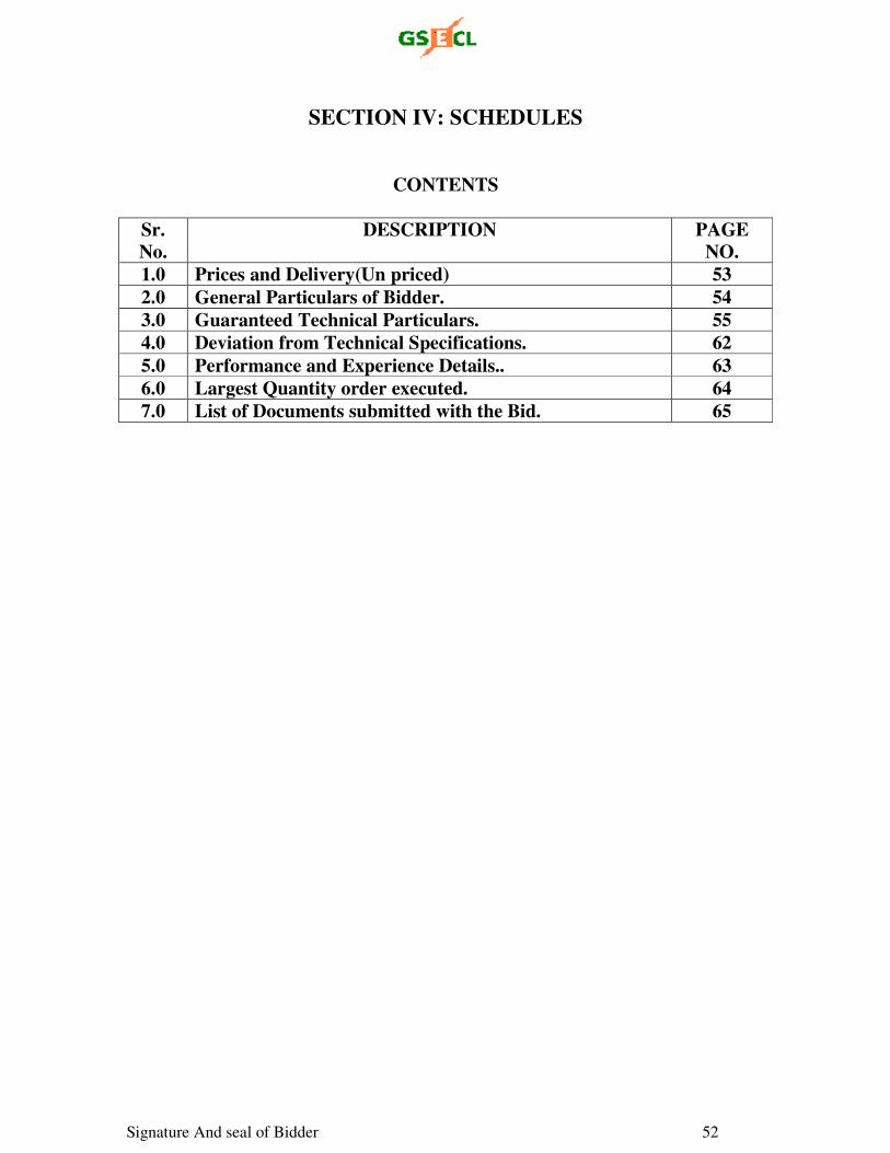
Signature And seal of Bidder 52
SECTION IV: SCHEDULES
CONTENTS
Sr. No.
DESCRIPTION PAGE NO.
1.0 Prices and Delivery(Un priced) 53
2.0 General Particulars of Bidder. 54
3.0 Guaranteed Technical Particulars. 55
4.0 Deviation from Technical Specifications. 62
5.0 Performance and Experience Details.. 63
6.0 Largest Quantity order executed. 64
7.0 List of Documents submitted with the Bid. 65
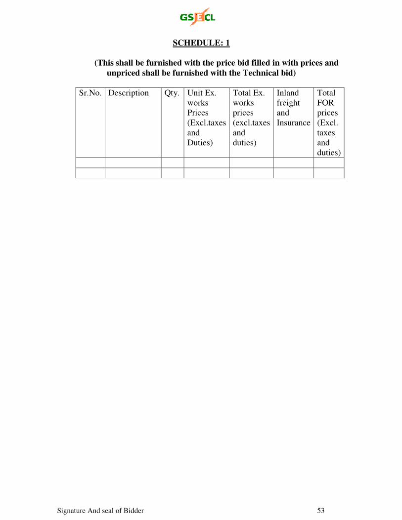
Signature And seal of Bidder 53
SCHEDULE: 1
(This shall be furnished with the price bid filled in with prices and
unpriced shall be furnished with the Technical bid)
Sr.No. Description Qty. Unit Ex.
works
Prices
(Excl.taxes
and
Duties)
Total Ex.
works
prices
(excl.taxes
and
duties)
Inland
freight
and
Insurance
Total
FOR
prices
(Excl.
taxes
and
duties)
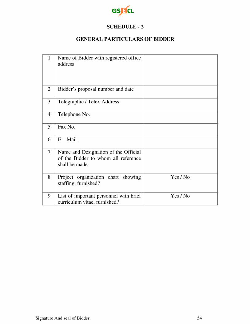
Signature And seal of Bidder 54
SCHEDULE - 2
GENERAL PARTICULARS OF BIDDER
1 Name of Bidder with registered office
address
2 Bidder’s proposal number and date
3 Telegraphic / Telex Address
4 Telephone No.
5 Fax No.
6 E – Mail
7 Name and Designation of the Official
of the Bidder to whom all reference
shall be made
8 Project organization chart showing
staffing, furnished?
Yes / No
9 List of important personnel with brief
curriculum vitae, furnished?
Yes / No
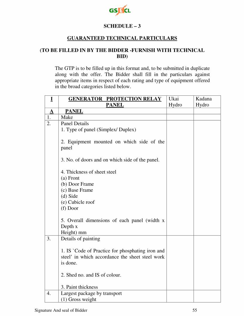
Signature And seal of Bidder 55
SCHEDULE – 3
GUARANTEED TECHNICAL PARTICULARS
(TO BE FILLED IN BY THE BIDDER -FURNISH WITH TECHNICAL
BID) The GTP is to be filled up in this format and, to be submitted in duplicate
along with the offer. The Bidder shall fill in the particulars against
appropriate items in respect of each rating and type of equipment offered
in the broad categories listed below.
I GENERATOR PROTECTION RELAY PANEL
Ukai
Hydro
Kadana
Hydro
A PANEL
1. Make
2. Panel Details
1. Type of panel (Simplex/ Duplex)
2. Equipment mounted on which side of the
panel
3. No. of doors and on which side of the panel.
4. Thickness of sheet steel
(a) Front
(b) Door Frame
(c) Base Frame
(d) Side
(e) Cubicle roof
(f) Door
5. Overall dimensions of each panel (width x
Depth x
Height) mm
3. Details of painting
1. IS `Code of Practice for phosphating iron and
steel’ in which accordance the sheet steel work
is done.
2. Shed no. and IS of colour.
3. Paint thickness
4. Largest package by transport
(1) Gross weight
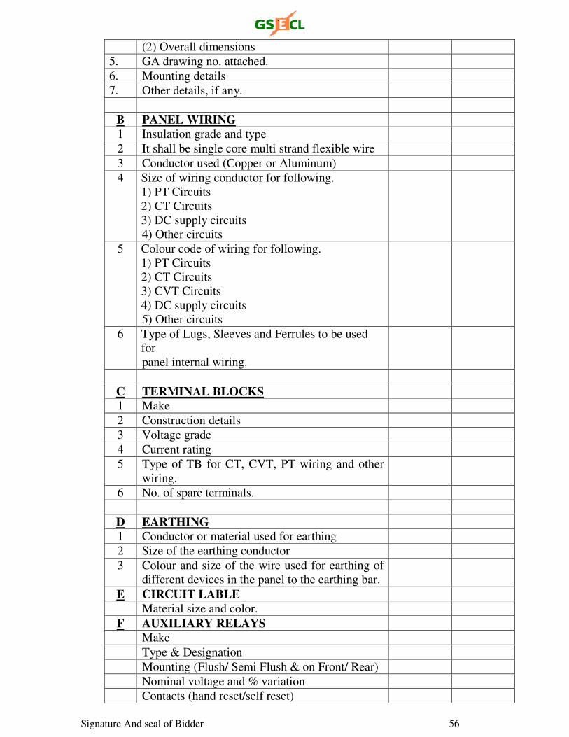
Signature And seal of Bidder 56
(2) Overall dimensions
5. GA drawing no. attached.
6. Mounting details
7. Other details, if any.
B PANEL WIRING
1 Insulation grade and type
2 It shall be single core multi strand flexible wire
3 Conductor used (Copper or Aluminum)
4 Size of wiring conductor for following.
1) PT Circuits
2) CT Circuits
3) DC supply circuits
4) Other circuits
5 Colour code of wiring for following.
1) PT Circuits
2) CT Circuits
3) CVT Circuits
4) DC supply circuits
5) Other circuits
6 Type of Lugs, Sleeves and Ferrules to be used
for
panel internal wiring.
C TERMINAL BLOCKS
1 Make
2 Construction details
3 Voltage grade
4 Current rating
5 Type of TB for CT, CVT, PT wiring and other
wiring.
6 No. of spare terminals.
D EARTHING
1 Conductor or material used for earthing
2 Size of the earthing conductor
3 Colour and size of the wire used for earthing of
different devices in the panel to the earthing bar.
E CIRCUIT LABLE
Material size and color.
F AUXILIARY RELAYS
Make
Type & Designation
Mounting (Flush/ Semi Flush & on Front/ Rear)
Nominal voltage and % variation
Contacts (hand reset/self reset)
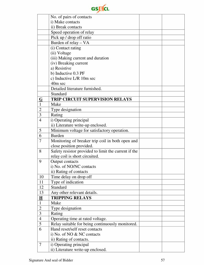
Signature And seal of Bidder 57
No. of pairs of contacts
i) Make contacts
ii) Break contacts
Speed operation of relay
Pick up / drop off ratio
Burden of relay – VA
(i) Contact rating
(ii) Voltage
(iii) Making current and duration
(iv) Breaking current
a) Resistive
b) Inductive 0.3 PF
c) Inductive L/R 10m sec
40m sec
Detailed literature furnished.
Standard
G TRIP CIRCUIT SUPERVISION RELAYS
1 Make
2 Type designation
3 Rating
4 i) Operating principal
ii) Literature write-up enclosed.
5 Minimum voltage for satisfactory operation.
6 Burden
7 Monitoring of breaker trip coil in both open and
close position provided.
8 Safety resistor provided to limit the current if the
relay coil is short circuited.
9 Output contacts
i) No. of NO/NC contacts
ii) Rating of contacts
10 Time delay on drop off
11 Type of indication
12 Standard
13 Any other relevant details.
H TRIPPING RELAYS
1 Make
2 Type designation
3 Rating
4 Operating time at rated voltage.
5 Relay suitable for being continuously monitored.
6 Hand reset/self reset contacts
i) No. of NO & NC contacts
ii) Rating of contacts.
7 i) Operating principal
ii) Literature write-up enclosed.
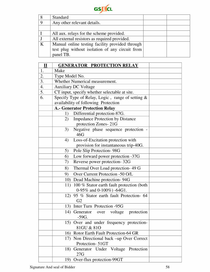
Signature And seal of Bidder 58
8 Standard
9 Any other relevant details.
I All aux. relays for the scheme provided.
J All external resistors as required provided.
K Manual online testing facility provided through
test plug without isolation of any circuit from
panel TB.
II GENERATOR PROTECTION RELAY
1. Make
2. Type Model No.
3. Whether Numerical measurement.
4. Auxiliary DC Voltage
5. CT input, specify whether selectable at site.
6. Specify Type of Relay, Logic , range of setting &
availability of following Protection
A.- Generator Protection Relay
1) Differential protection-87G.
2) Impedance Protection by Distance
protection Zones- 21G
3) Negative phase sequence protection -
46G
4) Loss-of-Excitation protection with
provision for instantaneous trip-40G.
5) Pole Slip Protection- 98G
6) Low forward power protection -37G
7) Reverse power protection- 32G
8) Thermal Over Load protection- 49 G
9) Over Current Protection -50 O/L
10) Dead Machine protection- 94G
11) 100 % Stator earth fault protection (both
0-95% and 0-100%) -64G1.
12) 95 % Stator earth fault Protection- 64
G2
13) Inter Turn Protection -95G
14) Generator over voltage protection
-59G.
15) Over and under frequency protection-
81GU & 81O
16) Rotor Earth Fault Protection-64 GR
17) Non Directional back –up Over Correct
Protection- 51GT
18) Generator Under Voltage Protection
27G
19) Over-flux protection-99GT
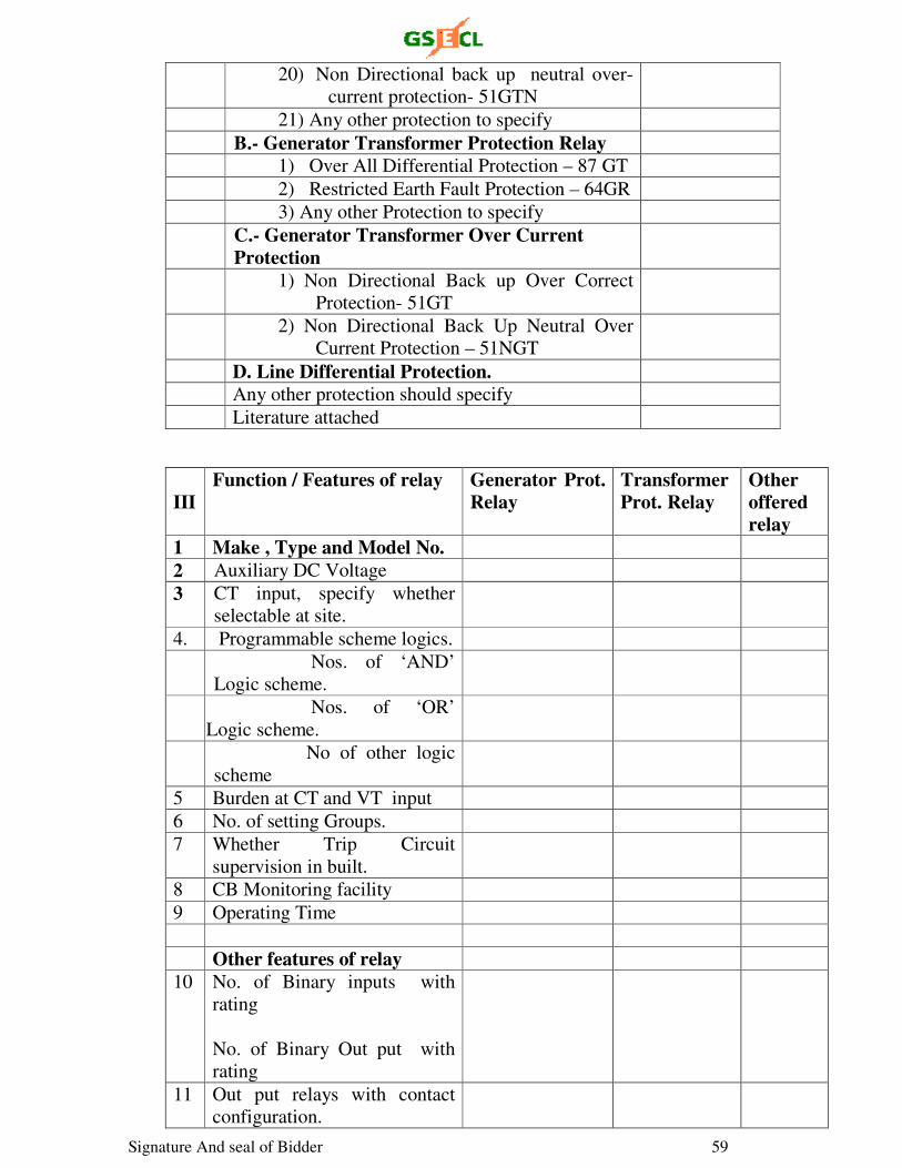
Signature And seal of Bidder 59
20) Non Directional back up neutral over-
current protection- 51GTN
21) Any other protection to specify
B.- Generator Transformer Protection Relay
1) Over All Differential Protection – 87 GT
2) Restricted Earth Fault Protection – 64GR
3) Any other Protection to specify
C.- Generator Transformer Over Current Protection
1) Non Directional Back up Over Correct
Protection- 51GT
2) Non Directional Back Up Neutral Over
Current Protection – 51NGT
D. Line Differential Protection.
Any other protection should specify
Literature attached
III
Function / Features of relay Generator Prot. Relay
Transformer Prot. Relay
Other offered relay
1 Make , Type and Model No.
2 Auxiliary DC Voltage
3 CT input, specify whether
selectable at site.
4. Programmable scheme logics.
Nos. of ‘AND’
Logic scheme.
Nos. of ‘OR’
Logic scheme.
No of other logic
scheme
5 Burden at CT and VT input
6 No. of setting Groups.
7 Whether Trip Circuit
supervision in built.
8 CB Monitoring facility
9 Operating Time
Other features of relay
10 No. of Binary inputs with
rating
No. of Binary Out put with
rating
11 Out put relays with contact
configuration.
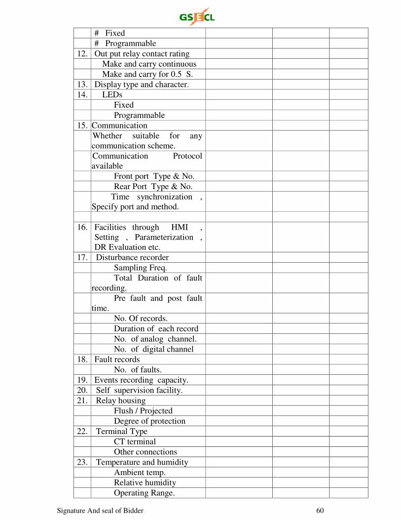
Signature And seal of Bidder 60
# Fixed
# Programmable
12. Out put relay contact rating
Make and carry continuous
Make and carry for 0.5 S.
13. Display type and character.
14. LEDs
Fixed
Programmable
15. Communication
Whether suitable for any
communication scheme.
Communication Protocol
available
Front port Type & No.
Rear Port Type & No.
Time synchronization ,
Specify port and method.
16. Facilities through HMI ,
Setting , Parameterization ,
DR Evaluation etc.
17. Disturbance recorder
Sampling Freq.
Total Duration of fault
recording.
Pre fault and post fault
time.
No. Of records.
Duration of each record
No. of analog channel.
No. of digital channel
18. Fault records
No. of faults.
19. Events recording capacity.
20. Self supervision facility.
21. Relay housing
Flush / Projected
Degree of protection
22. Terminal Type
CT terminal
Other connections
23. Temperature and humidity
Ambient temp.
Relative humidity
Operating Range.
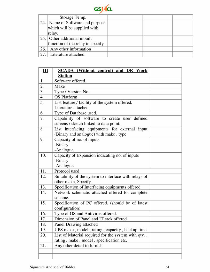
Signature And seal of Bidder 61
Storage Temp.
24. Name of Software and purpose
which will be supplied with
relay.
25. Other additional inbuilt
function of the relay to specify.
26. Any other information
27. Literature attached.
III SCADA (Without control) and DR Work Station
1. Software offered.
2. Make
3. Type / Version No.
4. OS Platform
5. List feature / facility of the system offered.
Literature attached.
6. Type of Database used.
7. Capability of software to create user defined
screens / sketch linked to data point.
8. List interfacing equipments for external input
(Binary and analogue) with make , type
9. Capacity of no. of inputs
-Binary
-Analogue
10. Capacity of Expansion indicating no. of inputs
-Binary
-Analogue
11. Protocol used
12. Suitability of the system to interface with relays of
other make, Specify.
13. Specification of Interfacing equipments offered
14. Network schematic attached offered for complete
scheme.
15. Specification of PC offered. (should be of latest
configuration)
16. Type of OS and Antivirus offered.
17. Dimension of Panel and IT rack offered.
18. Panel Drawing attached
19. UPS make , model , rating , capacity , backup time
20. List of Material required for the system with qty. ,
rating , make , model , specification etc.
21. Any other detail to furnish.
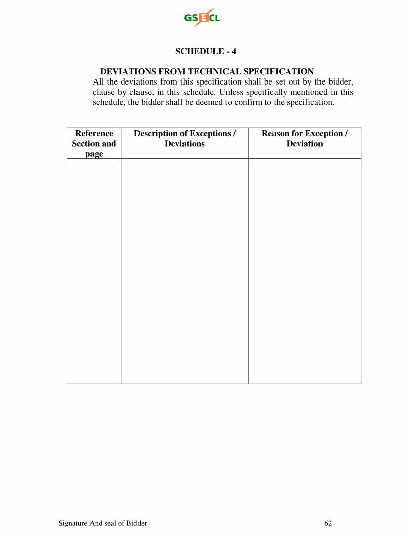
Signature And seal of Bidder 62
SCHEDULE - 4
DEVIATIONS FROM TECHNICAL SPECIFICATION All the deviations from this specification shall be set out by the bidder,
clause by clause, in this schedule. Unless specifically mentioned in this
schedule, the bidder shall be deemed to confirm to the specification.
Reference Section and
page
Description of Exceptions / Deviations
Reason for Exception / Deviation
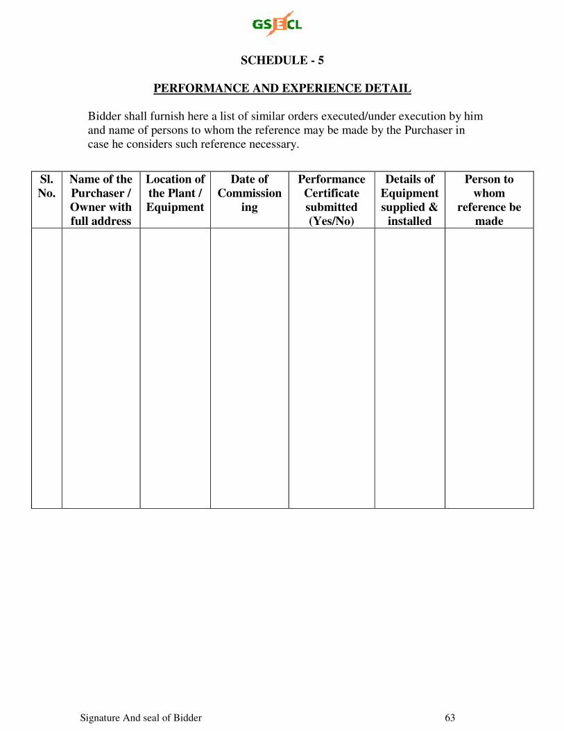
Signature And seal of Bidder 63
SCHEDULE - 5
PERFORMANCE AND EXPERIENCE DETAIL
Bidder shall furnish here a list of similar orders executed/under execution by him
and name of persons to whom the reference may be made by the Purchaser in
case he considers such reference necessary.
Sl. No.
Name of the Purchaser / Owner with full address
Location of the Plant / Equipment
Date of Commission
ing
Performance Certificate submitted (Yes/No)
Details of Equipment supplied &
installed
Person to whom
reference be made
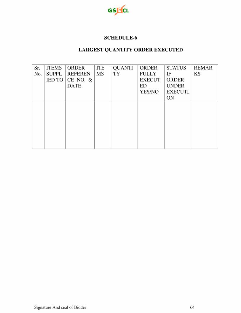
Signature And seal of Bidder 64
SCHEDULE-6
LARGEST QUANTITY ORDER EXECUTED
Sr.
No.
ITEMS
SUPPL
IED TO
ORDER
REFEREN
CE NO. &
DATE
ITE
MS
QUANTI
TY
ORDER
FULLY
EXECUT
ED
YES/NO
STATUS
IF
ORDER
UNDER
EXECUTI
ON
REMAR
KS
Signature And seal of Bidder 65
SCHEDULE - 7
LIST OF DOCUMENTS SUBMITTED WITH THE BIDS
Documents Title and Description