Embed Size (px)
Citation preview
23507060.2
SCHEDULE 3
DESIGN AND CONSTRUCTION SPECIFICATIONS
ROYAL INLAND HOSPITAL
PATIENT CARE TOWER
i
Schedule 3 – Design and Construction Specifications Royal Inland Hospital - Patient Care Tower
23507060.2
TABLE OF CONTENTS
PART 1. INTERPRETATION ................................................................................................................. 1
1.1 Definitions .................................................................................................................................. 1
1.2 Interpretation.............................................................................................................................. 5
1.3 Acronym List .............................................................................................................................. 6
PART 2. GENERAL ............................................................................................................................. 14
2.1 Standards ................................................................................................................................ 14
2.2 Use of Wood ............................................................................................................................ 27
2.3 Clinical Specifications .............................................................................................................. 27
2.4 Rooms and Spaces ................................................................................................................. 28
2.5 Processes and Submittals ....................................................................................................... 28
2.6 Heliport .................................................................................................................................... 28
PART 3. DESIGN PRINCIPLES AND OBJECTIVES ......................................................................... 31
3.1 Evidence Based Design .......................................................................................................... 31
3.2 Project Design Objectives ....................................................................................................... 31
3.3 Universal Design Philosophies ................................................................................................ 38
3.4 Sustainability............................................................................................................................ 38
3.5 Optimized Outcomes ............................................................................................................... 40
3.6 Adaptability, Flexibility and Expansion .................................................................................... 41
PART 4. SITE DEVELOPMENT REQUIREMENTS ............................................................................ 43
4.1 Site Considerations ................................................................................................................. 43
4.2 Site Preparation - Demolition ................................................................................................... 44
4.3 Urban Design and Site Development ...................................................................................... 46
4.4 Connections to Existing Hospital and Site Services ................................................................ 59
4.5 Site Infrastructure .................................................................................................................... 64
PART 5. BUILDING DESIGN REQUIREMENTS ................................................................................ 70
5.1 Adaptability and Flexibility ....................................................................................................... 70
5.2 Expandability ........................................................................................................................... 71
5.3 Post-Disaster Requirements .................................................................................................... 73
5.4 Architecture.............................................................................................................................. 73
5.5 Interior Environment .............................................................................................................. 103
5.6 Structural Design ................................................................................................................... 117
5.7 Bariatric Design ..................................................................................................................... 127
5.8 Renovations ........................................................................................................................... 128
5.9 Interim Post Anesthetic Recovery Room (PARR) ................................................................. 131
PART 6. FACILITIES CONSTRUCTION SUBGROUP SPECIFICATIONS ..................................... 137
6.1 Procurement and Contracting Requirements (Division 1) – NOT USED .............................. 137
6.2 Existing Conditions (Division 2) ............................................................................................. 137
ii
Schedule 3 – Design and Construction Specifications Royal Inland Hospital - Patient Care Tower
23507060.2
6.3 Concrete (Division 3) ............................................................................................................. 137
6.4 Masonry (Division 4) .............................................................................................................. 138
6.5 Metals (Division 5) ................................................................................................................. 139
6.6 Wood Plastics and Composites (including Millwork) (Division 6) .......................................... 143
6.7 Thermal and Moisture Protection (Division 7) ....................................................................... 147
6.8 Openings (Division 8) ............................................................................................................ 154
6.9 Finishes (Division 9) .............................................................................................................. 181
6.10 Specialties (Division 10) ........................................................................................................ 195
6.11 Equipment (Division 11) ........................................................................................................ 203
6.12 Furnishings (Division 12) ....................................................................................................... 206
6.13 Special Construction (Division 13)......................................................................................... 211
6.14 Conveying Equipment (Division 14) ...................................................................................... 212
6.15 Demountable Partitions ......................................................................................................... 228
PART 7. FACILITIES SERVICES SUBGROUP SPECIFICATIONS ................................................ 232
7.1 Mechanical Systems Design Principles ................................................................................. 232
7.2 Fire Suppression (Division 21) .............................................................................................. 238
7.3 Plumbing (Division 22) ........................................................................................................... 240
7.4 Heating, Ventilating and Air Conditioning (Division 23) ......................................................... 260
7.5 Major Equipment – Performance Specification ..................................................................... 275
7.6 Energy Model......................................................................................................................... 280
7.7 Integrated Automation (Division 25) ...................................................................................... 281
7.8 Electrical (Division 26) ........................................................................................................... 286
7.9 Communications (Division 27) ............................................................................................... 356
7.10 Electronic Safety and Security (Division 28) ......................................................................... 416
PART 8. SITE AND INFRASTRUCTURE SUBGROUP SPECIFICATIONS .................................... 440
8.1 Earthworks (Division 31) ........................................................................................................ 440
8.2 Exterior Improvements (Division 32) ..................................................................................... 441
8.3 Utilities (Division 33) .............................................................................................................. 445
APPENDIX 3A – CLINICAL SPECIFICATIONS AND FUNCTIONAL SPACE REQUIREMENTS
APPENDIX 3B – WOOD FIRST APPROPRIATE USE MATRIX
APPENDIX 3C – ROOM DATA SHEETS
APPENDIX 3D – ACOUSTIC AND NOISE CONTROL MEASURES
APPENDIX 3E – AUTHORITY COMMUNICATIONS INFRASTRUCTURE STANDARDS & SPECIFICATIONS
APPENDIX 3F – SYSTEMS RESPONSIBILITY MATRIX
APPENDIX 3G – SITE SERVICES
APPENDIX 3H – STAFF SAFETY GUIDELINES FOR INTERIOR HEALTH FACILITY DESIGN, NEW
BUILD OR RENOVATION PROJECTS
APPENDIX 3I – NATURAL GAS ROUTING
APPENDIX 3J – P3 SITE TOPOLOGY
APPENDIX 3K – INTERIM PARR ROOM DATA SHEET
APPENDIX 3L – ENCLOSED ATRIUM SUBMITTAL
1
Schedule 3 – Design and Construction Specifications Royal Inland Hospital - Patient Care Tower
23507060.2
Schedule 3
Design and Construction Specifications
PART 1. INTERPRETATION
1.1 Definitions
In this Schedule, in addition to the definitions set out in Schedule 1 of this Agreement:
“Allocated Data Port or Data Jack” A CAT6A cable that has been installed tested and certified with
proper terminations at both the field and head ends that can be patched into a Project Co provided and
provisioned network Switch Port (as per 7.9.5.1(1)) in the same rack in the communication room without
the need for additional infrastructure;
“ARCAL” means aircraft radio controlled aerodrome lighting where the pilot activates the Heliport lighting
by keying the microphone a specific number of times;
“Architectural Concrete” means all concrete exposed to view in all public areas on the interior and
exterior of the New Facility;
“Authority” has the meaning set out in Schedule 1;
“Authority End-Use Equipment” means Category 1 Equipment and Category 2 Equipment;
“Authority’s Engineer” means an Engineer hired by the Authority;
“Authority’s Quantity Surveyor” means a Quantity Surveyor hired by the Authority;
“Airborne Isolation Room (AIR)” – means a space designed, constructed and ventilated to limit the
spread of microorganisms from an infected occupant; with negative pressure ventilation conforming to
CSA Z8000 Canadian Health Care Facilities and CSA Z317.2 Special Requirements for Heating,
Ventilation, and Air Conditioning (HVAC) Systems in Health Care Facilities;
“Back of House” refers to rooms, spaces and circulation systems (corridors, elevators, stairs, etc.) which
are not accessible or visible to the general public and patients;
“BC Building Code” means the most recent version of the British Columbia Building Code;
“Borrowed Light” means that there shall be a window in the direction of an exterior window and the
centre of the space falls within the 8 meter light radius (10 meter light radius if the area is over 45 square
meters);
“Building” means the New Facility;
“Building Envelope Consultant” refers to building technology professionals who specialize in the design
and inspection of all elements of the building envelope, including roofs, walls, foundations, and their
component parts;
2
Schedule 3 – Design and Construction Specifications Royal Inland Hospital - Patient Care Tower
23507060.2
“Building Gross Area or Building Gross Square Meters” (BGSM) – The sum of all Building floor areas
measured to the outside face of exterior walls for all stories or areas having floor surfaces. Building gross
area includes Component gross area, General Circulation, mechanical and electrical space and exterior
walls;
“City” has the meaning set out in Schedule 1;
“Clinical Spaces” means patient areas used primarily in the direct care of patients and families
excluding; storage rooms, housekeeping rooms, and corridors. It includes spaces such as: waiting rooms,
medication rooms, nourishment alcoves or rooms, clean supply rooms, clean and soiled utility rooms and
Care Team Stations;
“Clinical Specifications and Functional Space Requirements” refers to Appendix 3A and includes a
description of the purpose of the New Facility and how the programs will be delivered at the Site;
“Component or Functional Component” A cohesive grouping of activities or spaces related by service
or physical arrangement. A planning component may or may not be a department since the term
”department” refers to an administrative organization rather than a functional organization of space and
activities;
“Convenient Access” refers to Components or items, which are located at a minimal distance from each
other and linked by horizontal and/or vertical circulation, the location of these items are optimized for
efficiency of flow and avoid corners, jogs or obstructions such as columns that create interference. The
Authority may consider vertical circulation as providing Convenient Access on a case by case basis
pending review and approval;
“CPTED” means Crime Prevention Through Environmental Design. CPTED is a multi-disciplinary
approach to deterring undesirable and criminal activity and behavior through environmental design;
“dBA” refers to the unit of sound pressure level when the "A weighting filter" is used;
“Design Life” means the period of time during which the item is expected by its designers to work within
its specified parameters; in other words, the anticipated life expectancy of the item;
“Direct Access” means rooms, spaces, areas or Components, which are contiguous and avoid
movement through other circulation systems or spaces. Upon review and approval by the Authority, an
acceptable alternative to horizontal contiguity between Components may be vertical contiguity by means
of a dedicated elevator or internal stairs; vertical contiguity by means of a dedicated elevator or internal
stairs shall not be acceptable for the following key adjacencies; Level 4N Post Anesthetic Recovery Room
(PARR) Area and Surgical Services, Main Entrance Vestibule and Reception Desk / Registration
Cubicles, existing MDR and the MDR Cart Marshalling Areas (Sterile and Soiled), and the existing loading
docks and Materials Management Functions;
“Direct Natural Light” means that the space shall have an exterior window and the centre of the space
falls within the 8 meter light radius measured from the entire length of the window (10 meter light radius if
the area is over 45 square meters); the window glass opening shall be 1.7 square meters in area minimum,
unless otherwise specified in this Schedule;
“Emergency Operations Centre” has the meaning set out in Section 5.3.3 of this Schedule;
3
Schedule 3 – Design and Construction Specifications Royal Inland Hospital - Patient Care Tower
23507060.2
“Enclosed Atrium” has the meaning set out in 5.4.11 Enclosed Atrium Requirements;
“Equipped” means all rooms and/or spaces in the Appendix 3A Clinical Specifications and Functional
Space Requirements shall be completely finished, equipped and commissioned;
“Evidence Based Design” or “EBD” has the meaning defined in section 3.1.1;
“FMO” means Facilities Maintenance and Operations or Plant Services staff at Royal Inland Hospital;
“Front of House” refers to rooms, spaces and circulation systems (corridors, elevators, stairs, etc.)
which are non-restricted, accessible and visible to the general public;
“Functional Space Requirements” refers to the list of required spaces to be included in the design of the
New Facility. The Functional Space Requirements document is located in the Appendix 3A Clinical
Specifications and Functional Space Requirements;
“Future Expansion”, means space that will not be built now but which Project Co shall include in
planning and design of the New Facility;
“General Circulation” refers to Components linked by horizontal and/or vertical circulation corridors,
stairs or elevators to be used by public, visitors and staff;
“Hazardous Substance” has the meaning set out in Schedule 1;
“Heliport” has the meaning set out in Section 2.6 of this Schedule; and means an aerodrome in respect
of which a Heliport certificate issued under Subpart 5 of CARs Part III is in force;
“H1” refers to a Heliport able to accommodate a multi-engine helicopter that will allow a safe landing or
continue flight and clear all obstacles under the flight path by 4.5 m, with one engine inoperative;
“Hospital” has the meaning set out in Schedule 1;
“Indicative Design” has the meaning as set out in section 2.4.2 of this Schedule;
“Internal Circulation” refers to Components linked internally through a horizontal connection such as a
door or opening and avoid movement through other circulation systems;
“Life Safety System or Life Safety Equipment” refers to any equipment or infrastructure that either
provides, monitors or supports life safety or is designed to protect and evacuate the RIH Campus in
emergencies including patient vital signs, RTLS, fire alarm, medical gases and nurse call systems;
“Make Good” means preparing new surfaces which are identical to adjacent surfaces, and finished off in
such a manner that there are no visible traces (at a distance of 600 mm), between existing work and the
work of new patching. Making good therefore, extends to the complete re-finishing of entire surface
areas as is necessary, to junction points or inside or outside corners of roofs, exterior walls, partitions,
ceiling and landscaping/paving;
“Medical Device Reprocessing (MDR)” refers to the department which processes and provides supplies
of sterile instruments, linen packs, dressing and other sterile items used in patient care;
4
Schedule 3 – Design and Construction Specifications Royal Inland Hospital - Patient Care Tower
23507060.2
“Millwork” refers to fixed (non-movable) architectural woodwork for casework, walls, ceiling, doors,
paneling, trim and partitions;
“Net Area or Net Square Meters (NSM)” The horizontal area of space assignable to a specific function.
The net area of rooms is measured to the inside face of wall surfaces;
“New Facility” has the meaning set out in Schedule 1;
“Obstacle” means an object that could have an adverse effect on the safe operation of aircraft in flight or
on the ground;
“Opening Day Layout” means the layout of the all rooms and areas which will be Equipped and put into
service as of the Service Commencement Date. Refer to Appendix 2E Equipment List for the quantity of
rooms that will be Equipped on the Service Commencement Date;
“Other Site Facilities” has the meaning set out in Schedule 1;
"Outbreak Control Zone" a collection of rooms and spaces that can be isolated in area and negatively
pressurized from the surrounding areas to mitigate the spread of airborne infections;
“Project Co End-Use Equipment” means end-use equipment and communications equipment provided
by Project Co as required for its own use for the performance of its obligations under this Agreement;
“Project Design Objectives” means the project design objectives set out in Section 3.2 of this Schedule;
“Provide” means supply and install;
“Recurrent Room” refers to repetitious spaces or multiples of the same room type in the Appendix 3A
Clinical Specifications and Functional Space Requirements;
“RPBD” reduced pressure principle backflow device;
“Restricted Circulation” refers to Components linked by restricted horizontal and/or vertical circulation
corridors, stairs or elevators to be used by staff, registered patients and services and are not for use by
the general public;
“Room Data Sheets” has the meaning set out in Schedule 1;
“RIH” has the meaning set out in Schedule 1;
“RIH Campus” has the meaning set out in Schedule 1;
“Seamless Integration” has the meaning set out in section 7.9.2.1(9) of this Schedule;
“Select Campus Wide System” has the meaning set out in Schedule 4 Appendix 4D Section 2.4(c).
Refer to Appendix 3F Systems Responsibility Matrix for Select Campus Wide Systems and Project Co
obligations;
“Site” has the meaning set out in Schedule 2 Design and Construction Protocols;
5
Schedule 3 – Design and Construction Specifications Royal Inland Hospital - Patient Care Tower
23507060.2
“STC” means Sound Transmission Class and is used in this Schedule 3 as a rating requirement for the
degree to which a Building partition attenuates airborne sound;
“Switch Port” An active port on a network switch in the MCC/BCC, or telecommunication room that can
be connected to a data jack to change the status of a data jack from unallocated to allocated;
“Systems Furniture” refers to a series of movable or demountable modular panels, work surfaces,
shelves, and other similar items from a single manufacturer including all components that are collectively
required to complete a workstation, reception desk, transaction counter, or similar and includes
infrastructure systems;
“Telecommunication Outlet” Refer to definition provided in Appendix 3E Authority Communications
Infrastructure Standards & Specifications;
“TLOF” means a touchdown and lift off area, which consists of a load-bearing area on which a helicopter
may touch down or lift off;
“Unallocated Data Port or Data Jack” A CAT6A cable that has been installed, tested and certified with
proper terminations at both the field and head ends and does not have a provisioned network Switch Port
in the same rack in the communications room, but has the ability to become allocated by patching into an
Authority provided network Switch Port if required post substantial completion and handover of the
network to the Authority;
“Un-Equipped” means the rooms and/or spaces which are specified as being completely finished and
commissioned except for having equipment installed. The room and/or space shall be designed and
constructed at Service Commencement to accommodate and accept the Placeholder Equipment;
“Unusable Area” means horizontal area which does not contribute to the function of the room as
described in Appendix 3A Clinical Specifications and Functional Space Requirements;
“Void Space” means space which is trapped between walls and/or structure and is not intended to be
finished or used;
“Wayfinding” refers to information systems that guide people through a physical environment and
enhance their understanding and experience of the space;
“Westland Parking” means parking on the RIH Campus located on the land parcel located on the west
side of RIH Campus approximately 8,300 NSM adjacent to the existing Children Circle Daycare.
1.2 Interpretation
1.2.1 This Schedule is written as an output specification and defines what Project Co shall
achieve in the Design and Construction. Except as expressly stated otherwise, Project
Co will carry out the Design and Construction as required and contemplated by each
provision of this Schedule and its Appendices whether or not the provision is written as
an obligation of Project Co or is stated in the imperative form.
6
Schedule 3 – Design and Construction Specifications Royal Inland Hospital - Patient Care Tower
23507060.2
1.2.2 Where “cost effective”, “appropriate”, “sufficient”, “minimize” and related and similar terms
are used, they are to be construed and interpreted in terms of whether they are cost
effective, appropriate, sufficient, minimizing, etc. from the perspective of a prudent public
owner of a major public hospital building who balances capital costs against
maintenance, operations, clinical efficiency and other non-capital costs over the life of the
Building.
1.3 Acronym List
1.3.1 AFF – Above Finished Floor Level
1.3.2 AFUE - Annual Fuel Utilization Efficiency
1.3.3 AIR –Airborne Isolation Room
1.3.4 ANF – Natural Convection Cooling plus Forced Air Cooling
1.3.5 ANN – Natural Convection Cooling
1.3.6 ANSI - American National Standards Institute
1.3.7 AOC - Architectural Openings Consultant
1.3.8 ARCAL – Aircraft Radio Control of Aerodrome Lighting
1.3.9 ASHRAE - American Society of Heating, Refrigerating and Air-conditioning Engineers
1.3.10 ASME - American Society of Mechanical Engineers
1.3.11 ASPE - American Society of Plumbing Engineers
1.3.12 ASTM - American Society for Testing and Materials
1.3.13 ATM – Automated Teller Machine
1.3.14 AT4 – Ascom Telligence 4.0 C600 System
1.3.15 ATS – Automatic Transfer Switch
1.3.16 AV / IT – Audio Visual / Information Technology
1.3.17 AWMAC – Architectural Woodworker Manufacturers Association of Canada
1.3.18 BCCSS – BC Clinical and Support Services
1.3.19 BCERMS - British Columbia Emergency Response Management System
1.3.20 BCICA - British Columbia Insulation Contractors Association
1.3.21 BCLNA - British Columbia Landscape & Nursery Association
7
Schedule 3 – Design and Construction Specifications Royal Inland Hospital - Patient Care Tower
23507060.2
1.3.22 BCSLA - British Columbia Society of Landscape Architects
1.3.23 BICSI - Building Industry Consulting Service International
1.3.24 BMS - Building Management System
1.3.25 CARs – Canadian Aviation Regulations
1.3.26 CATV – Community Access Television
1.3.27 CCD – Charge Couple Device
1.3.28 CDP – Centralized Distribution Panels
1.3.29 CEC – Canadian Electrical Code
1.3.30 CFC – Chlorofluorocarbon
1.3.31 CFL – Compact Fluorescent Lamp
1.3.32 CGA - Compressed Gas Association
1.3.33 CGSM – Component Gross Square Metres
1.3.34 CIF – Common Intermediate Format
1.3.35 CISCA - Ceiling Interior Systems Construction Association
1.3.36 CLSI – Clinical Laboratory Standards Institute
1.3.37 CMU – Concrete Masonry Unit
1.3.38 CODEC – Coder/Decoder
1.3.39 CPTED - Crime Prevention Through Environmental Design
1.3.40 CPU – Central Processing Unit
1.3.41 CRTC – Canadian Radio-television and Telecommunications Commission
1.3.42 CSA - Canadian Standards Association
1.3.43 CT - Computer Tomography
1.3.44 CTAS – Canadian Triage Acuity Scale
1.3.45 Cx – Commissioning
1.3.46 DCS – Day Care Surgery
1.3.47 DDC – Direct Digital Controls
8
Schedule 3 – Design and Construction Specifications Royal Inland Hospital - Patient Care Tower
23507060.2
1.3.48 DFO – Department of Fisheries and Oceans
1.3.49 DID – Direct Inward Dialling
1.3.50 DISS – Diameter Index Safety System
1.3.51 DSSS – Direct Sequence Spread Spectrum
1.3.52 EBD – Evidence Based Design
1.3.53 ECG – Electrocardiography
1.3.54 ED –Emergency Department
1.3.55 EEG - Electroencephalogram
1.3.56 EIA/TIA – Electronics Industry Association/Telecommunications Industry Association
1.3.57 EHR – Electronic Health Record
1.3.58 EMI – Electromagnetic Interference
1.3.59 EMS - Emergency Medical Services
1.3.60 EMT – Electric Metallic Tubing
1.3.61 ENT – Ear Nose Throat
1.3.62 EOC-Emergency Operations Centre
1.3.63 FACP – Fire Alarm Control Panel
1.3.64 FATO – Final Approach and Take-off Area
1.3.65 FE - Future Expansion
1.3.66 FEMA – Federal Emergency Management Agency
1.3.67 FIPPA – Freedom of Information and Protection of Privacy Act
1.3.68 FM – Factory Mutual
1.3.69 FP – Family Practice/Practitioner
1.3.70 GPS – Global Positioning Satellite
1.3.71 HAZMAT – Hazardous Materials or Substances
1.3.72 HCF – Health Care Facility
1.3.73 HCFC – Hydrochlorofluorocarbons
9
Schedule 3 – Design and Construction Specifications Royal Inland Hospital - Patient Care Tower
23507060.2
1.3.74 HEPA - High Efficiency Particulate Air
1.3.75 HID - High Intensity Discharge
1.3.76 HIMSS – Healthcare Information and Management Systems Society
1.3.77 HIS – Health Information Services/Hospital Information System
1.3.78 HL7 – Health Level 7
1.3.79 HLD - High Level Disinfection
1.3.80 HOA – Hand/Off/Auto
1.3.81 HOM – Heliport Operations Manual
1.3.82 HP – Horsepower
1.3.83 HRC – High Rupting Capacity (fuse type)
1.3.84 HVAC - Heating, Ventilating and Air-Conditioning
1.3.85 IAQ-Interior Air Quality
1.3.86 IDS / IPS – Intrusion Detection System / Intrusion Prevention System
1.3.87 IEEE - Institute of Electrical and Electronic Engineers
1.3.88 IP – Internet Protocol
1.3.89 IT – Information Technology
1.3.90 IMIT – Information Management Information Technology
1.3.91 IPU - Inpatient Unit
1.3.92 IR – Interventional Radiology
1.3.93 ISO – International Organization for Standardization
1.3.94 IT/Tel – Information Technology / Telecommunication
1.3.95 IV – Intravenous
1.3.96 KW – Kilowatt
1.3.97 KWH – Kilowatt hours
1.3.98 KV – Kilovolt
1.3.99 KVA – Kilovolt Ampere

10
Schedule 3 – Design and Construction Specifications Royal Inland Hospital - Patient Care Tower
23507060.2
1.3.100 LDR – Labour, Delivery, and Recovery Room
1.3.101 LAN – Local Area Network
1.3.102 LCD – Liquid Crystal Display
1.3.103 LED – Light Emitting Diode
1.3.104 LEED - LEED® Leadership in Energy and Environmental Design
1.3.105 LEED HC – LEED® HC Leadership in Energy and Environmental Design 2009 for Health
Care – US Green Building council
1.3.106 Mb – Megabit
1.3.107 MCP – Motor Circuit Protector
1.3.108 MDR – Medical Device Reprocessing
1.3.109 MEO – Medical Emergency Operation
1.3.110 MHSU – Mental Health and Substance Use
1.3.111 MFP – Multi-Function Peripheral (or Multi-Function Printer)
1.3.112 MMCD – Master Municipal Contract Documents
1.3.113 MPI – Master Painters Institute
1.3.114 MRI – Magnetic Resonance Imaging
1.3.115 NEMA – National Electrical Standards Association
1.3.116 NFCA – National Floor Covering Association
1.3.117 NFPA – National Fire Protection Association
1.3.118 NTSC – National Television Standards Committee
1.3.119 NM – Nuclear Medicine
1.3.120 NRC – National Research Council
1.3.121 NSM – Net Square Metres
1.3.122 NVG – Night Vision Goggles
1.3.123 OA – Outdoor Air
1.3.124 OHSR – Occupation Health and Safety Regulations
11
Schedule 3 – Design and Construction Specifications Royal Inland Hospital - Patient Care Tower
23507060.2
1.3.125 OR – Operating Room
1.3.126 OFDM – Orthogonal Frequency Division Multiplexing
1.3.127 OS&Y – Open Stem and Yoke
1.3.128 OT – Occupational Therapy/Therapist
1.3.129 PACS – Picture Archiving and Communication System
1.3.130 PARR – Post Anesthetic Recovery Room
1.3.131 PBX – Private Branch Exchange
1.3.132 PCC – Patient Care Coordinator
1.3.133 PC – Personal Computer
1.3.134 PDA – Personal Digital Assistant
1.3.135 PET – Positron Emission Tomography
1.3.136 PIPEDA – Personal Information Protection and Electronic Document Act
1.3.137 PoE – Power Over Ethernet
1.3.138 PPE - Personal Protective Equipment
1.3.139 PT - Physiotherapy/Physiotherapist
1.3.140 PTS - Pneumatic Tube System
1.3.141 PTZ – Pan Tilt Zoom
1.3.142 PVC – Polyvinyl Chloride
1.3.143 RBR5 – Rauland-Borg Responder V Nurse Call System
1.3.144 RCDD – Registered Communications Distribution Designer
1.3.145 RCABC – Roofing Contractors Association of British Columbia
1.3.146 RN – Registered Nurse
1.3.147 RO – Reverse Osmosis
1.3.148 RT – Respiratory Therapy/Therapist
1.3.149 RTLS – Real Time Location System
1.3.150 SAGA - System of Approach Azimuthal Guidance
12
Schedule 3 – Design and Construction Specifications Royal Inland Hospital - Patient Care Tower
23507060.2
1.3.151 SES – Safety Engineering Society
1.3.152 SIP – Session Initiated Protocol
1.3.153 SMACNA – Sheet Metal and Air Conditioning Contractors National Association
1.3.154 SMDR – Station Message Detail Recording
1.3.155 SNR – Signal to Noise Ratio
1.3.156 SPD- Surge Protective Device
1.3.157 SQL – Structured Query Language
1.3.158 STAT – Statim (“immediately”)
1.3.159 STC – Sound Transmission Coefficient
1.3.160 STI – Sound Transmission Index
1.3.161 TAB – Testing, adjusting and balancing
1.3.162 TCO – Total Cost of Ownership
1.3.163 TCP – Transmission Control Protocol
1.3.164 TDM – Time Division Multiplexing
1.3.165 THD - Total Harmonic Distortion
1.3.166 TIA – Telecommunications Industry Association
1.3.167 TTMAC – Terrazzo and Tile Manufacturers Association of Canada
1.3.168 TVOC – Total Volatile Organic Compounds
1.3.169 TVSS - Transient Voltage Surge Suppressor
1.3.170 ULC - Underwriters’ Laboratories of Canada
1.3.171 UPS – Uninterruptible Power Supply
1.3.172 US – Ultrasonography/Ultrasound
1.3.173 V - Volt
1.3.174 VAR – Volt Ampere Reactive power
1.3.175 VAV – Variable Air Volume
1.3.176 VFD - Variable Frequency Drive
13
Schedule 3 – Design and Construction Specifications Royal Inland Hospital - Patient Care Tower
23507060.2
1.3.177 VLAN – Virtual Local Area Network
1.3.178 VOC – Volatile Organic Compounds
1.3.179 VoIP – Voice over Internet Protocol
1.3.180 WAN – Wide Area Network
1.3.181 WAP2 – Wireless Application Protocol 2
1.3.182 WMM – Wi-Fi Multimedia
14
Schedule 3 – Design and Construction Specifications Royal Inland Hospital - Patient Care Tower
23507060.2
PART 2. GENERAL
2.1 Standards
2.1.1 Project Co will undertake the Design and Construction:
2.1.1.1 in accordance with the standards set out in this Schedule;
2.1.1.2 in accordance with the BC Building Code and all applicable Laws, and City of
Kamloops including:
2.1.1.2(1) Building Bylaw No. 11-81;
2.1.1.2(2) Zoning Bylaw 5-1-2850 and Zoning Bylaw Amendment Procedure
Bylaw No. 5-1-2002;
2.1.1.2(3) Development Permit Procedure Bylaw No. 5-1-227 and
Development Variance Permit Procedure Bylaw No. 5-1-1208;
2.1.1.2(4) Development Cost Charges Bylaw No. 48-100;
2.1.1.2(5) Development and Land Use Application Fees Bylaw No. 5-1-2560.
2.1.1.3 having regard for the concerns, needs and interests of:
2.1.1.3(1) all persons who will be New Facility users;
2.1.1.3(2) all Governmental Authorities;
2.1.1.3(3) the community;
2.1.1.3(4) City of Kamloops.
2.1.1.4 in accordance with Good Industry Practice; and
2.1.1.5 to the same standard that an experienced, prudent and knowledgeable long term
owner of a high quality health care building in North America operated publicly
would employ.
2.1.2 If more than one of the above standards is applicable then the highest such standard will
apply.
2.1.3 If Project Co wishes to make reference to a code or standard from a jurisdiction outside
of Canada, then Project Co will demonstrate to the Authority’s satisfaction that such code
or standard meets or exceeds the requirements of this Schedule.
2.1.4 Guidelines listed in section 2.1.7 will be interpreted as standards and Project Co will
comply with them as such.
15
Schedule 3 – Design and Construction Specifications Royal Inland Hospital - Patient Care Tower
23507060.2
2.1.5 The most recent version of any standard and guideline listed in section 2.1.6 or
elsewhere in this document, that is in effect when the Project Agreement is signed, will
govern.
2.1.6 In accordance with CSA Z8000 Canadian Health Care Facilities unless otherwise agreed
to by the Authority; provided however that in the event of any conflict between CSA
Z8000 and the express provisions of this Schedule 3, the express provisions of this
Schedule 3 prevail.
2.1.7 Without limiting Section 2.1.1 of this Schedule, Project Co will undertake the Design and
Construction in compliance with all applicable codes, standards and guidelines, including:
2.1.7.1 AIA Guidelines for Design and Construction of Health Care Facilities, 2010;
2.1.7.2 AAMI TIR 34; Water for Reprocessing of Medical devices.
2.1.7.3 BC Building Code;
2.1.7.4 B.C. Fire Code;
2.1.7.5 B.C. Plumbing Code;
2.1.7.6 National Fire Code;
2.1.7.7 Ambulance Station Design Standards, British Columbia Ambulance Service, BC
Emergency and Health Services August 23, 2007.
2.1.7.8 WorkSafe BC ergonomic regulations:
2.1.7.8(1) Occupational Health and Safety Regulations
2.1.7.8(2) Ergonomics (MSI) Requirements
2.1.7.9 The requirements of the Authority, document Section 01550 - Infection Control
Measures during Construction; available in the Data Room.
2.1.7.10 BCICA Quality Standards Manual for Mechanical Insulation.
2.1.7.11 Canadian Council on Health Services Accreditation Program, Latest Edition.
2.1.7.12 Ministry of Health — Province of British Columbia Provincial Quality, Health &
Safety Standards and Guidelines for Secure Rooms in Designated Mental Health
Facilities under the B.C. Mental Health Act.
2.1.7.13 Staff Safety Guidelines for IH Healthcare Facilities Design Guide for the Built
Environment of Behavioral Health Facilities Apr. 2016 Ed. 7.1 Canadian
Biosafety Standard, Second Edition.
2.1.7.14 OHSAH Guidelines for Locating Sharps Disposal Containers.
16
Schedule 3 – Design and Construction Specifications Royal Inland Hospital - Patient Care Tower
23507060.2
2.1.7.15 Workplace Health and Safety Emergency Wash Stations Guidelines;
2.1.7.16 Sustainability:
2.1.7.16(1) US Green Building Council – LEED for Health Care;
2.1.7.16(2) The Green Guide for Health Care;
2.1.7.16(3) Green Globes – Environment Assessment for New Buildings;
2.1.7.16(4) BOMA (Building Owner and Managers Association) Go Green
Program;
2.1.7.16(5) ASHRAE Green Healthcare Construction Guidance Statement,
Jan 2002;
2.1.7.16(6) Sustainable Health Care Architecture –by Robin Guenther and Gail
Vittori;
2.1.7.16(7) Canadian Building Green Hospitals Checklist - Canadian Coalition
for Green Health Care;
2.1.7.16(8) Natural Resources Canada Energy Innovators Initiative;
2.1.7.16(9) Building Materials for the Environmentally Hypersensitive, CMHC;
2.1.7.16(10) ASHRAE Proposed Standard 189 - Standard for the Dosing and
High Performance Green Buildings;
2.1.7.16(11) ASTM E917.24401-1 Life Cycle Cost Assessment Methodology;
2.1.7.16(12) LEED® New Building (NC) Program;
2.1.7.16(13) BC Hydro High Performance Building Program.
2.1.7.17 All ANSI / ASHRAE standards and guidelines including:
2.1.7.17(1) 52.2-2007: Method of Testing General Ventilation Air-Cleaning
Devices for Removal Efficiency by Particle Size;
2.1.7.17(2) 55-2004: Thermal Environmental Conditions for Human
Occupancy;
2.1.7.17(3) 62.1-2007: Ventilation for Acceptable Indoor Air Quality;
2.1.7.17(4) 90.1-2007: Energy Standard for Buildings Except Low Rise
Residential Buildings;
2.1.7.17(5) 111-2008: Practices for Measurement, Testing, Adjusting &
Balancing of Building HVAC Systems;
17
Schedule 3 – Design and Construction Specifications Royal Inland Hospital - Patient Care Tower
23507060.2
2.1.7.17(6) 129-1997: Measuring Air Change Effectiveness;
2.1.7.17(7) 135-2004: Data Communication Protocol for Building Automation &
Control Networks;
2.1.7.17(8) 170-2008 Ventilation of Health Care Facilities.
2.1.7.18 All ASHRAE standards and guidelines including:
2.1.7.18(1) Handbooks: 2009 Fundamentals, 2006 Refrigeration, 2007 HVAC
Applications, 2008 HVAC Systems and Equipment;
2.1.7.18(2) Design of Smoke Control Systems;
2.1.7.18(3) ASHRAE Guideline 12-2000 - Minimizing the Risk of Legionellosis
Associated with Building Water Systems;
2.1.7.18(4) ASHRAE Guideline 1.1-2007 – HVAC & R Technical
Requirements for the Commissioning process;
2.1.7.18(5) ASHRAE Guideline 0-2005 – The Commissioning Process;
2.1.7.18(6) ANSI/ASHREA/IESNA 90.1 Energy Standard for buildings except
low-rise residential buildings;
2.1.7.18(7) ASHRAE System Design Manual for Hospitals and Clinics.
2.1.7.19 All ANSI / ASME standards and guidelines including:
2.1.7.19(1) B31.1 Power Piping;
2.1.7.19(2) B31.9 Building Services Piping;
2.1.7.19(3) Section VIII: Pressure Vessels;
2.1.7.19(4) Section IX: Welding Qualifications;
2.1.7.19(5) Unfired pressure vessels; and
2.1.7.19(6) AWS D1.3-98 - Structural Welding Code - Sheet Steel.
2.1.7.20 All ANSI / EIA standards and guidelines including:
2.1.7.20(1) 568-C.1 & 568-C.2 (CSA-0T529) Commercial Building
Telecommunications Cabling Standard – Parts 1 & 2:
2.1.7.20(2) 568-C.3 (CSA-T529) Commercial Building Telecommunications
Cabling Standard – Part 3;
18
Schedule 3 – Design and Construction Specifications Royal Inland Hospital - Patient Care Tower
23507060.2
2.1.7.20(3) 569-C (CSA-T530) Commercial Building Standard for
Telecommunications Pathways and Spaces;
2.1.7.20(4) 606-B (CSA-T528) Administration Standard for
Telecommunications Infrastructure of Commercial Buildings;
2.1.7.20(5) 607-B (CSA-527) Commercial Grounding and Bonding
Requirements for Telecommunications; and
2.1.7.20(6) 758 Customer Owned Outside Plant Telecommunications Cabling
Standard.
2.1.7.21 All ANSI / TIA standards and guidelines including:
2.1.7.21(1) 942 Telecommunications Infrastructure Standard for Data Centers;
2.1.7.21(2) TSB-162 Telecommunications Cabling Guidelines for Wireless
Access Points;
2.1.7.21(3) 1179 Healthcare Facility Telecommunications Infrastructure
Standard.
2.1.7.22 ANSI / ESNA American National Standard Practice for Lighting.
2.1.7.23 ASPE Plumbing Engineering Design Handbook, Volumes 1-4.
2.1.7.24 All ASTM standards and guidelines including:
2.1.7.24(1) ASTM C568-03 - Standard Specification for Limestone Dimension
Stone;
2.1.7.24(2) ASTM C615-03 - Standard Specification for Granite Dimension
Stone;
2.1.7.24(3) ASTM C503-05 - Standard Specification for Marble Dimension
Stone;
2.1.7.24(4) ASTM C616-03 - Standard Specification for Quartz-Based
Dimension Stone;
2.1.7.24(5) BCSLA and BCLNA - BC Landscape Standard – Current Edition;
2.1.7.24(6) ASTM C260 / C260M – 10a – Standard Specification for Air-
Entraining Admixtures for Concrete;
2.1.7.24(7) ASTM C494 / C494M – 13 – Standard Specification for Chemical
Admixtures for Concrete;
2.1.7.24(8) ASTM C645 – 14e1 – Standard Specification for Non-structural
Steel Framing Members;
19
Schedule 3 – Design and Construction Specifications Royal Inland Hospital - Patient Care Tower
23507060.2
2.1.7.24(9) ASTM A36 A36M-12 – Standard Specification for Carbon
Structural Steel;
2.1.7.24(10) ASTM A193 / A193M-14 – Standard Specification for Alloy –Steel
and Stainless Steel Bolting for High Temperature or High Pressure
Service and Other Special Purpose Applications;
2.1.7.24(11) ASTM A307-12 – Standard Specification for Carbon Steel Bolts,
Studs, and Threaded Rod 60000 PSI Tensile Strength;
2.1.7.24(12) ASTM S325-10e1 – Standard Specification for Structural Bolts,
Steel, Heat Treated, 120/105 ksi Minimum Tensile Strength;
2.1.7.24(13) ASTM A326M-13 – Standard Specification for Structural Bolts,
Steel, Bolts, Steel, Heat Treated, 830 MPa Minimum Tensile
Strength (Metric);
2.1.7.24(14) ASTM A490-12 – Standard Specification for Structural Bolts, Alloy
Steel, Heat Treated, 150 ksi Minimum Steel Strength;
2.1.7.24(15) ASTM A490M-12 - Standard Specification for High Strength
Structural Steel Bolts, Classes 10.9 and 10.9.3, for Structural Steel
joints (Metric);
2.1.7.24(16) ASTM A653 / A653M-13 – Standard Specification for Steel Sheet,
Zinc-Coated (Galvanized) or Zinc-Iron Alloy-Coated
(Galvannealed) by the Hot-Dip Process;
2.1.7.24(17) ASTM A792 / A792M-10 – Standard Specification for Steel Sheet,
55% Aluminum-Zinc Alloy-Coated by the Hot-Dip Process;
2.1.7.24(18) ASTM A47 / A47M-99(2014) – Standard Specification for Ferritic
Malleable Iron castings;
2.1.7.24(19) ASTM A955 / A955M – 17 – Standard Specification For Deformed
& Plain Stainless-Steel Bars For Concrete Reinforcement;
2.1.7.24(20) ASTM C645 – 04 Standard Specification for Non-structural Steel
Framing Members;
2.1.7.24(21) ASTM D2047 Standard Test Method for Static Coefficient of
Friction of Polish-Coated Flooring Surfaces;
2.1.7.24(22) ASTM C 1349-04;
2.1.7.24(23) ASTM C 1048-04;
2.1.7.24(24) ASTM C 1036-06;
20
Schedule 3 – Design and Construction Specifications Royal Inland Hospital - Patient Care Tower
23507060.2
2.1.7.24(25) ASTM D4828 – 94 Standard Test Methods for Practical
Washability of Organic Coatings;
2.1.7.24(26) ASTM D3450 – Test Method for Washability Properties of Interior
Architectural Coatings;
2.1.7.24(27) ASTM D1308 – Standard Test Method for Effect of Household
Chemicals on Clear and Pigmented Organic Finishes;
2.1.7.24(28) ASTM D543ASTM D543 – 14 Standard Practices for Evaluating
the Resistance of Plastics to Chemical Reagents;
2.1.7.24(29) ASTM E 1300-04e1 – Standard Practice for Determining Load
Resistance of Glass in Buildings.
2.1.7.25 AAMA 501.8 Standard Test Method for Determination of Resistance to Human
Impact of Window Systems Intended for Use in Psychiatric Applications.
2.1.7.26 All CAN ULC standards and guidelines including:
2.1.7.26(1) S524 Standards for the Installation of Fire Alarm Systems; and
2.1.7.26(2) S537 Standards for Verification of Fire Alarm Systems.
2.1.7.27 CGA - P-2.1: Standard for Medical / Surgical Vacuum Systems in Hospitals.
2.1.7.28 All CAN/CSA standards and guidelines including:
2.1.7.28(1) B52-05: Mechanical Refrigeration Code;
2.1.7.28(2) B51-2003: Boiler, Pressure vessel and Pressure Piping Code;
2.1.7.28(3) B64.10 Selection and Installation of Backflow Preventers;
2.1.7.28(4) B139 Installation Code for Oil Burning Equipment;
2.1.7.28(5) B149.1-05: Natural Gas and Propane Installation Code;
2.1.7.28(6) B651-95: Barrier Free Design;
2.1.7.28(7) C22.1 & C22.2 Canadian Electrical Code as adopted in British
Columbia;
2.1.7.28(8) C282 Emergency Electrical Power Supply for Buildings;
2.1.7.28(9) Z32-15 Electrical Safety and Essential Electrical System in Health
Care Facilities;
2.1.7.28(10) Z317.5 Illumination Systems in Health Care Facilities;
21
Schedule 3 – Design and Construction Specifications Royal Inland Hospital - Patient Care Tower
23507060.2
2.1.7.28(11) Z318.5 Commissioning of Electrical Equipment and Systems in
Health Care Facilities;
2.1.7.28(12) Medical gas pipeline systems – Part 1: Pipelines for medical
gases, medical vacuum, medical support gases, and anaesthetic
gas scavenging systems;
2.1.7.28(13) Z316.5 Fume hoods and associated Exhaust Systems;
2.1.7.28(14) Z317.1 Special Requirements for Plumbing Installations in Health
Care Facilities;
2.1.7.28(15) Z317.2-15 Special Requirements for Heating, Ventilation, and Air
Conditioning (HVAC) Systems in Health Care Facilities;
2.1.7.28(16) Z318.0-93 Commissioning of Health Care Facilities;
2.1.7.28(17) Z318.1-95 Commissioning of HVAC Systems in Health Care
Facilities;
2.1.7.28(18) Z317.3 Infection control During Construction or Renovation of
Health Care Facilities;
2.1.7.28(19) A23.4-09 - Precast Concrete - Materials and Construction;
2.1.7.28(20) W186-M1990 (R2012) - Welding of Reinforcing Bars in Reinforced
Concrete Construction;
2.1.7.28(21) A370-14 - Connectors for Masonry;
2.1.7.28(22) A23.1-14/A23.2-14 - Concrete Materials and Methods of Concrete
Construction / Test Methods and Standard Practices for Concrete;
2.1.7.28(23) A23.3-14 – Design of concrete structures;
2.1.7.28(24) G40.20-13/G40.21-13 – General Requirements for rolled or welded
structural quality steel / Structural quality steel;
2.1.7.28(25) G30.18-09 – Carbon steel bars for concrete reinforcement;
2.1.7.28(26) S269.3-M92 (R2013) – Concrete Formwork;
2.1.7.28(27) S832-06 – Seismic Risk Reduction of Operational and Functional
Components (OFCS of buildings);
2.1.7.28(28) S478-95 (R2007) – Guideline on Durability of Buildings;
2.1.7.28(29) S413-14 Parking Structures;
2.1.7.28(30) S16-14 Design of Steel Structures;
22
Schedule 3 – Design and Construction Specifications Royal Inland Hospital - Patient Care Tower
23507060.2
2.1.7.28(31) S136-12 North American Specification for Design of Cold Formed
Steel Structural Members;
2.1.7.28(32) S304-14 Design of Masonry Structures;
2.1.7.28(33) S832-06 Guidelines for Seismic Risk Reduction of Operational and
Functional Components of Buildings;
2.1.7.28(34) W47.1-09 Certification of Companies for fusion welding of steel;
2.1.7.28(35) W48-14 Filler metals and allied materials for metal arc welding;
2.1.7.28(36) W55.3-08 (R2013) Certification of companies for resistance
welding of steel and aluminum;
2.1.7.28(37) W59-13 Welded steel construction (metal arc welding);
2.1.7.28(38) W59.2M1991 (R2013) Welded Aluminum Construction;
2.1.7.28(39) W186-M1990 (R2012) Welding of Reinforcing Bars in Reinforced
Concrete Construction;
2.1.7.28(40) Z317.1-09 Special requirements for plumbing installations in
Health Care facilities;
2.1.7.28(41) Z314.7-03 Steam sterilizers for Health Care Facilities;
2.1.7.28(42) Z317.11-02 Area requirements for Health Care Facilities;
2.1.7.28(43) Z317-10.09 Handling of waste materials in Health Care Facilities
and Veterinary Health Care Facilities;
2.1.7.28(44) Z317.13-07 Infection Control During Construction, Renovation, and
Maintenance of Health Care Facilities;
2.1.7.28(45) Z8000–11 September 2011 Canadian Health Care Facilities;
2.1.7.28(46) A660-10 Certification of manufacturers of steel building systems;
2.1.7.28(47) CSA Z32 Electrical Safety and Mandatory Electrical systems in
Health Care Facilities, 2015 Edition or later;
2.1.7.28(48) CSA Standard Z317.5 Illumination Systems in Health Care
Facilities;
2.1.7.28(49) CSA C282 Emergency electrical power supply for buildings, 2015
Edition or later;
2.1.7.28(50) CSA-C22.3 No. 1, Overhead Systems;
23
Schedule 3 – Design and Construction Specifications Royal Inland Hospital - Patient Care Tower
23507060.2
2.1.7.28(51) CSA C22.2 No.65, Wire Connectors;
2.1.7.28(52) CSA C22.2 No.41, Grounding and Bonding Equipment;
2.1.7.28(53) CSA C22.2 No.0.4, Bonding of Electrical Equipment;
2.1.7.28(54) CSA C22.2 No.40, Cut-out, Junction and Pull Boxes;
2.1.7.28(55) CSA C22.2 No. 45, Rigid Metal Conduit;
2.1.7.28(56) CSA C22.2 No. 56, Flexible Metal Conduit and Liquid-Tight
Flexible Metal Conduit;
2.1.7.28(57) CSA C22.2 No. 83, Electrical Metallic Tubing;
2.1.7.28(58) CSA C22.2 No. 211.2, Rigid PVC (Unplasticized) Conduit;
2.1.7.28(59) CSA C22.2 No. 100 0, Motors and Generators;
2.1.7.28(60) CSA C22.2 No. 145 Motors and Generators for use in Hazardous
Locations;
2.1.7.28(61) CSA C22.2 No.184.1, Solid State Dimming Controls (Bi national
standard with UL 1472);
2.1.7.28(62) CSA C22.2 No.58, High Voltage Isolating Switches;
2.1.7.28(63) CSA G40.20/G40.21, General Requirements for Rolled or Welded
Structural Quality Steel/Structural Quality Steel;
2.1.7.28(64) CSA C9, Dry Type Transformers;
2.1.7.28(65) CSA C22.2 No. 58, High Voltage Isolating Switches;
2.1.7.28(66) CSA C22.2 No.29, Panelboards and enclosed Panelboards;
2.1.7.28(67) CSA C22.2 No.144.1, Ground Fault Circuit Interrupters;
2.1.7.28(68) CSA Z314.0-13 Medical Device Reprocessing – General
requirements;
2.1.7.28(69) CSA Z314.8-14 Decontamination of Reusable Medical Devices;
2.1.7.28(70) CSA Z314.3-14 Effective Sterilization in Health Care Settings by
the Steam Process;
2.1.7.28(71) CSA Z314.23-12 Chemical Sterilization of Reusable Medical
Devices;
2.1.7.28(72) CSA Z386-14 – Safe Use of Lasers in Health Care;
24
Schedule 3 – Design and Construction Specifications Royal Inland Hospital - Patient Care Tower
23507060.2
2.1.7.28(73) CSA A231.1/A231.2, Precast Concrete Paving Slabs/Precast
Concrete Pavers;
2.1.7.28(74) CSA W59-13 Welded Steel Construction;
2.1.7.28(75) CAN/CGSB-12.20-M89 – Structural Design of Glass for Buildings;
2.1.7.28(76) CAN/CSA-S157-05/S157.1-05 – Strength Design in Aluminum.
2.1.7.29 All NFPA standards and guidelines including:
2.1.7.29(1) 10-2002: Standard for Portable Fire Extinguishers;
2.1.7.29(2) 13: Standard for the Installation of Sprinkler Systems;
2.1.7.29(3) 14: Standard for the Installation of Standpipe System;
2.1.7.29(4) 30: Flammable and Combustible Liquids Code;
2.1.7.29(5) 55: Storage, Use, and Handling of Compressed and Liquefied
Gases in Portable Containers;
2.1.7.29(6) 56F: Non-flammable Medical Gas System;
2.1.7.29(7) 90A - Current Edition: Standard for Installation of Air Conditioning
and Ventilation Systems;
2.1.7.29(8) 92A - Current Edition: Standard for Smoke-Control Systems
Utilizing Barriers and Pressure Differences; and
2.1.7.29(9) 101 - Current Edition: Life Safety Code.
2.1.7.30 All IEEE standards and guidelines including:
2.1.7.30(1) 802.1 series for Interworking, Security, Audio/Video Bridging and
Data Centre Bridging;
2.1.7.30(2) 802.3 series of Ethernet Standards; and
2.1.7.30(3) 802.11 series of Wireless Standards.
2.1.7.31 All NETA standards and guidelines including:
2.1.7.31(1) ATS International Electrical Testing Association (Acceptance
Testing Specifications); and
2.1.7.31(2) MTS Standards for Maintenance Testing.
2.1.7.32 BICSI Telecommunications Distribution Methods Manual (TDMM).
25
Schedule 3 – Design and Construction Specifications Royal Inland Hospital - Patient Care Tower
23507060.2
2.1.7.33 Code Plus, Physical Design Components for an Elder Friendly Hospital, 2nd
Edition 2015.
2.1.7.34 BC Supplement to TAC Geometric Design Guide.
2.1.7.35 Master Municipal Construction Documents (MMCD) – 2009 Platinum Edition
Volume II.
2.1.7.36 Master Municipal Construction Documents (MMCD) – Platinum Edition
Supplementary Updates.
2.1.7.37 City of Kamloops Earthwork Control Bylaw No. 4-19.
2.1.7.38 City of Kamloops Traffic Bylaw No. 23-30.
2.1.7.39 City of Kamloops Tree Protection Bylaw No. 24-35.
2.1.7.40 Fire Underwriter Survey – Water Supply for Public Fire Protection, 1999.
2.1.7.41 Sheet Metal and Air Conditioning Contractors National Association Inc.
(SMACNA) Manuals.
2.1.7.42 Industrials Ventilation Manual.
2.1.7.43 Hydronic Institute Manuals.
2.1.7.44 American Society of Plumbing Engineer Manuals.
2.1.7.45 Associated Air Balance Council (AABC).
2.1.7.46 BC Guidelines for Decontamination of Patients in Health Facilities.
2.1.7.47 Best Practices for Hand Hygiene in All Heath Care Settings and Programs,
British Columbia Ministry of Health.
2.1.7.48 Design Guide for Improving Hospital Safety in Earthquakes, Floods, and High
Winds: Providing Protection to People and Buildings. Date published: 06/2007
FEMA Publication Number 577.
2.1.7.49 RD–52 Design Guide for Nuclear Substance Laboratories and Nuclear Medicine
Rooms.
2.1.7.50 Applicable Municipality Bylaws.
2.1.7.51 Ministry of Environment (MOE).
2.1.7.52 CAN/CSA-B72 Installation Code for Lightning Protection Systems.
2.1.7.53 Illuminating Engineering Society of North America Lighting Handbook -
Reference & Application.
26
Schedule 3 – Design and Construction Specifications Royal Inland Hospital - Patient Care Tower
23507060.2
2.1.7.54 Commercial Building Telecommunications Cabling Standard TIA/EIA 568-C.1-
2010 Including all Addendum’s and Latest Drafts for requirements of Category
6.Commercial Building Standard For Telecommunications Pathways And Spaces
TIA 569-C-2012 including addendum.
2.1.7.55 TIA/EIA-606-B-2012 including addendum - Administration Standard For The
Telecommunications Infrastructure Of Commercial Buildings (CSA T528).
2.1.7.56 Commercial Building Grounding And Bonding Requirements For
Telecommunications TIA-607-B-2011.
2.1.7.57 Provincial Lightning Rods Act.
2.1.7.58 FGI Guidelines for Design and Construction of Health Care Facilities (Electrical,
Security, Lighting, Communication reference section).
2.1.7.59 CSA/CAN3-C235, Preferred Voltage Levels for AC Systems, 0 to 50,000 V.
2.1.7.60 CAN/CSA C22.2 No. 131, Type TECK 90 Cable.
2.1.7.61 NEMA WC7 ICEA S 66 524, Cross Linked Polyethylene Wire and Cable for
Transmission and Distribution.
2.1.7.62 CAN/CSA C22.2No.18, Outlet Boxes, Conduit Boxes, Fittings and Associated
Hardware.
2.1.7.63 CAN/CSA C22.2 No. 18, Outlet Boxes, Conduit Boxes, Fittings and Associated
Hardware, A National Standard of Canada.
2.1.7.64 CAN/CSA C22.1 No.126.1, Metal Cable Tray Systems.
2.1.7.65 NEMA VE 1, Metal Cable Tray Systems.
2.1.7.66 ANSI C37.121, Unit Substations Requirements.
2.1.7.67 CSA C22.2 No.178.1, Automatic Transfer Switches for bypass/isolating switches.
2.1.7.68 CAN/CSA-C2, Single-Phase and Three-Phase Distribution Transformers, Types
ONAN and LNAN.
2.1.7.69 IEEE C57.19.91, IEEE Standard test code for dry-type distribution and power
transformers.
2.1.7.70 CAN/CSA C22.2 No.31, Switchgear Assemblies.
2.1.7.71 NEMA PB2.2, Application Guide for Ground Fault Protection Devices for Equipment.
2.1.7.72 NFPA 20, Stationary Fire Pumps for Fire Protection.
27
Schedule 3 – Design and Construction Specifications Royal Inland Hospital - Patient Care Tower
23507060.2
2.1.7.73 Geometric Design Guide for Canadian Roads (2017) by the Transportation
Association of Canada (TAC).
2.1.7.74 The Canadian Landscape Standard published by the Canadian Nursery
Landscape Association and the Canadian Society of Landscape Architects,
current edition.
2.1.7.75 Standards for Landscape Irrigation published by Irrigation Industry Association of
British Columbia, current edition.
2.2 Use of Wood
2.2.1 Use wood as a featured material in both the interior and exterior of the New Facility.
2.2.2 As contemplated by the Wood First Act (British Columbia), Project Co will incorporate
wood products into the design of the New Facility to the extent that the use of wood
products is consistent with the requirements of this Schedule and the BC Building Code.
2.2.3 Wood will be used where indicated as “Appropriate” in Appendix 3B Wood First
Appropriate Use Matrix. Wood shall not be used where indicated as “Inappropriate”.
2.2.4 The term “Alternative Solution” used in this section specifically refers to this term as
described in the 2012 BC Building Code.
2.3 Clinical Specifications
2.3.1 Project Co will design and construct the Building:
2.3.1.1 So that it accommodates all of the spaces, activities, functions, design features
and adjacencies described in the Appendix 3A Clinical Specifications and
Functional Space Requirements;
2.3.1.2 In accordance with the requirements of Appendix 3A Clinical Specifications and
Functional Space Requirements, and Appendix 3C Room Data Sheets, subject
to any adjustments or refinements made in accordance with Appendix 2C Review
Procedure;
2.3.1.3 The net square metre area for all rooms shall not be more than 2% smaller than
the required area listed in the Functional Space Requirements. Project Co shall
provide a rationale for each variation and demonstrate to the Authority’s
satisfaction that affected rooms retain their functionality. If, in the Authority’s
opinion, the room does not meet the required functionality, the full net square
metres shall be provided as stated in Appendix 3A Clinical Specifications and
Functional Space Requirements.
2.3.1.4 Project Co shall avoid creating Unusable Area which includes:
2.3.1.4(1) circulation space within an area required for access;
28
Schedule 3 – Design and Construction Specifications Royal Inland Hospital - Patient Care Tower
23507060.2
2.3.1.4(2) non-functional areas created by acute or obtuse wall angles;
2.3.1.4(3) L shaped rooms; and
2.3.1.4(4) all other space where the functionality is encumbered by structure,
columns, shafts or projections.
2.3.1.5 The net square metre area for all rooms required per Appendix 3A Clinical
Specifications and Functional Space Requirements shall exclude Unusable Area.
2.4 Rooms and Spaces
2.4.1 Notwithstanding anything in Appendix 3A Clinical Specifications and Functional Space
Requirements, Project Co will design and construct the Building to include all rooms and
spaces as required to comply with the terms of this Project Agreement, including
sufficient rooms and spaces as necessary for the operation and maintenance of the
Building and for Project Co to perform the services in accordance with this Project
Agreement. Spaces provided for operations, maintenance and other FM requirements
shall not impact clinical function or public and staff access to the Building.
2.4.2 The Authority’s architectural consultant undertook an Indicative Design of the Building
(the “Indicative Design”). The Indicative Design is based on the Appendix 3A Clinical
Specifications and Functional Space Requirements but also reflects consultations with
potential New Facility users. Drawings are available in the Data Room.
2.4.3 Project Co may use the Indicative Design as a basis for its design, but the Authority
makes no representation as to the accuracy or completeness of any aspect of the
Indicative Design.
2.4.4 Project Co will be completely responsible for all aspects of the Design and Construction
whether or not it uses all or any part of the Indicative Design, and Project Co will
independently verify the accuracy of any information contained in or inferred from the
Indicative Design if Project Co uses any of such information in its design.
2.5 Processes and Submittals
2.5.1 For all requirements for User Group Consultations and Review Procedures including:
shop drawings, commissioning requirements, demonstrations, training, mock-ups and
medical equipment, refer to Schedule 2 Design and Construction Protocols and its
associated appendices.
2.6 Heliport
2.6.1 Project Co will provide a Transport Canada certified Heliport (the “Heliport”) on the roof
of the Building that meets the requirements of this Schedule and all applicable standards,
including:
2.6.1.1 CARs Part III, Subpart 5, CARs Standard 325 – Heliports, CARs Standard 621
and referenced standards;

29
Schedule 3 – Design and Construction Specifications Royal Inland Hospital - Patient Care Tower
23507060.2
2.6.1.2 ICAO / Annex 14, Volume II where applicable;
2.6.1.3 NFPA 70 National Electrical Code;
2.6.1.4 NFPA 70B Recommended Practice for Electrical Equipment Maintenance;
2.6.1.5 IEEE C2 National Electrical Safety Code; and
2.6.1.6 NFPA 418 Standard for Heliports.
2.6.2 Provide documentation, operating and maintenance manuals and training on all Heliport
systems and installations.
2.6.3 Prepare all documents required for Transport Canada certification.
2.6.4 Heliport Design
2.6.4.1 Classification: The Heliport shall meet H1 classification;
2.6.4.2 Level of Service: The Heliport shall be designed for day operations and night
operations under NVGs and unaided;
2.6.4.3 Design Helicopter Size: The Heliport shall be designed to accommodate a
helicopter with a total length of 17.5 m;
2.6.4.4 Dimensions: The TLOF shall be a minimum 21.5m x 21.5m;
2.6.4.5 Aviation Criteria: The flight paths and presence of obstructions will permit use by
the current BC EHS helicopter air ambulance;
2.6.4.6 Flight Paths: A minimum of two flight paths shall be provided, each with an arc of
45 degrees or greater, 180 degrees flight path separation, centre arc to centre
arc, and aligned with the prevailing winds;
2.6.4.7 Obstacle Clearance: Each flight path shall have adequate obstacle clearance to
meet rearward and lateral clearance requirements contained in the Aircraft Flight
Manual Category “A” Supplements for the Bell 412EP, Bell 412EPi, Sikorsky
S76C++, MD902, H145, AW139, AW169 and other common air ambulance
types. The Heliport shall be situated such that one edge of the TLOF,
perpendicular to the flight paths, is within 30 feet of the building edge;
2.6.4.8 Above ground flammable liquids, compressed gas, and liquefied gas (such as
7.3.4 Medical Gas Systems, 7.3.5.5 Propane & Natural Gas Systems, and
7.8.5.1(8) Emergency Power) shall not be situated within or below any part of the
Heliport flight paths;
2.6.5 Walkway
30
Schedule 3 – Design and Construction Specifications Royal Inland Hospital - Patient Care Tower
23507060.2
2.6.5.1 The walkway connecting the TLOF with the Staff/Emergency Service Elevator
vestibule shall have provisions for a future metal edge protection to reduce the
risk of stretcher wheels from rolling over the edge. The walkway shall have a
centreline marking. The walkway shall be a minimum width of 2600 mm;
2.6.5.2 TLOF and walkway surfaces shall have a non-slip coating;
2.6.5.3 Safety net mesh and fuel containment materials will be hot dipped galvanized.
2.6.6 Heliport Vestibule
2.6.6.1 The Heliport vestibule shall be designed to provide:
2.6.6.1(1) An unobstructed view of the TLOF;
2.6.6.1(2) Either an unobstructed view or high definition IP Video
Surveillance of all approach and departure paths;
2.6.6.1(3) Interior day and night lighting, ensuring the lighting does not affect
pilot’s night vision or NVG operation;
2.6.6.1(4) Work station suitable for installation of and/or storage of personal
protective equipment, portable radios, AC receptacles, telephone
for internal and external calls, IP video monitor, document filing
and display and writing surface;
2.6.6.1(5) Access to nearby washroom facilities. Provide key pad punch code
locks at stairwell doors for controlled access to adjacent floors.
2.6.7 Warning Signs
2.6.7.1 The Heliport shall have adequate helicopter warning, restricted access and no
smoking signs installed at each Hospital interior and exterior access location.
2.6.8 Certification Requirements
2.6.8.1 Project Co shall:
2.6.8.1(1) Provide a Heliport Operations Manual (HOM) that receives
approval by Transport Canada;
2.6.8.1(2) Submit Heliport details suitable for aeronautical publications
(Canada Flight Supplement);
2.6.8.1(3) Be responsible for providing foam fire suppression test(s) as part
of the Heliport certification process;
2.6.8.1(4) Provide training for Heliport safety personnel as identified by
regulations and standards;
31
Schedule 3 – Design and Construction Specifications Royal Inland Hospital - Patient Care Tower
23507060.2
2.6.8.1(5) Conduct an obstacle assessment for marking and lighting pursuant
to CAR 305.37(2) and Standard 325 and shall be responsible for
marking and lighting on-site obstacles pursuant to Standard 621;
2.6.8.1(6) Prepare obstacle marking and lighting direction and drawings for
all off-site obstacles;
2.6.8.1(7) Prepare all Aeronautical Assessment Forms and Nav Canada
Land Use Notifications for required on-site obstacles;
2.6.8.1(8) Conduct a survey and H1 obstacle assessment and provide an H1
obstacle chart pursuant to CAR 305.29(3) and suitable for
helicopter performance calculations and submission for
aeronautical publications;
2.6.8.1(9) Be responsible for chartering a suitable helicopter, approved by
Transport Canada, for the purpose of day and night aerial
assessments as part of the certification process;
2.6.8.1(10) Provide a Heliport Emergency Response Plan as part of the HOM;
ensure consultation with and satisfaction by Kamloops Fire and
Rescue with the Emergency Response Plan.
PART 3. DESIGN PRINCIPLES AND OBJECTIVES
3.1 Evidence Based Design
3.1.1 In undertaking the design of the Building, Project Co will apply Evidence Based Design
methodologies to achieve the Project Design Objectives. Evidence Based Design means
that decisions about the design of the Building will be based on credible research,
information derived from comparable North American projects, and information about
Authority operations, in order to achieve the best possible outcomes. The goal of EBD is
to deliver measurable improvements, for example in the Authority’s patient and workflow
outcomes, productivity, economic performance, and patient satisfaction. Project Co will
provide EBD documentation through the Schedule 2 Appendix 2C Review Procedure for
the Authority's use to consider, implement, teach, etc.
3.2 Project Design Objectives
3.2.1 The vision for the Royal Inland Hospital Patient Care Tower Project is to:
3.2.1.1 Build patient care through an achievable and affordable capital renewal solution
that supports the Hospital’s tertiary care role now and into the future;
3.2.1.2 Provide a state of the art New Facility with technology that improve the patient
experience, maximize health improvement within a healing environment, and
improve the physical working conditions for staff;
32
Schedule 3 – Design and Construction Specifications Royal Inland Hospital - Patient Care Tower
23507060.2
3.2.1.3 Align services with identified specialized and acute care needs for patients living
in the Thompson Cariboo Shuswap; and
3.2.1.4 Develop the campus to provide improved patient flow and access to services
within the RIH Campus.
3.2.2 Guiding Principles and Critical Success Factors
3.2.2.1 The overarching principles guiding the Project are:
3.2.2.1(1) Develop spaces to maximize the long-term flexibility and
adaptability of interior spaces and to maintain a high level of
utilization;
3.2.2.1(2) Leverage and review the 7 Lean flows of health services
(Information, Patient, Providers, Medications, Supplies, Process
Engineering, Equipment) through key design and operational
commissioning stages of the Project;
3.2.2.1(3) Incorporate patient-centered and elder-friendly design concepts to
improve the patient experience;
3.2.2.1(4) Incorporate standardization of spaces and incorporate lessons
learned from other major capital healthcare projects wherever
possible;
3.2.2.1(5) Engage users and patients in planning and design;
3.2.2.1(6) Focus on environmental sustainability stewardship through building
design and operation; and
3.2.2.1(7) Support clinical education activities to help rectify the critical
shortage of health care providers.
3.2.3 Project Objectives
3.2.3.1 In support of the Project Vision and Guiding Principles, the Project Objectives
are:
3.2.3.1(1) Deliver a New Facility that is patient centred, supports the guiding
principles and achieves departmental or Component objectives;
3.2.3.1(2) Incorporate design features that enhance the well-being of
patients, families, visitors, staff and communities including those
with Aboriginal ancestry;
3.2.3.1(3) Improve patient access and flow within the Site;
33
Schedule 3 – Design and Construction Specifications Royal Inland Hospital - Patient Care Tower
23507060.2
3.2.3.1(4) Improve the model of care delivery and patient outcomes
(including patient safety) through application of patient centred,
evidence-based design principles and standards for health care
facility design and construction;
3.2.3.1(5) Provide separation of flows in the circulation system between
public, patient and materials distribution by providing Front of
House and Back of House corridors is a desired outcome;
3.2.3.1(6) Create a healthy and safe work environment that improves
employee engagement, recruitment and retention, and provides an
environment that minimizes the opportunity for workplace injuries;
3.2.3.1(7) Support the Information Management Information Technology
(IMIT) strategic plan by providing a robust, flexible technical
infrastructure;
3.2.3.1(8) Implement integrated electronic health records across the patient
continuum of care, including advanced clinical functionality such as
electronic clinical documentation, computerized physician order
entry, closed loop medication verification and bedside medication
verification;
3.2.3.1(9) Optimize utilization of health care services and resource
efficiencies to assist in health system sustainability initiatives;
3.2.3.1(10) THIS SECTION REMOVED
3.2.3.1(11) Maintain full 24/7 Hospital operations throughout the construction
and operational transition phase for the New Facility; and
3.2.3.1(12) Minimize overall capital and operating costs for the New Facility.
3.2.4 Departmental Objectives
3.2.4.1 General Medical/Surgical Inpatient Unit
3.2.4.1(1) Provide a 30-bed inpatient unit to accommodate medical or
surgical patients depending on need. The unit will provide flexibility
in use as patient population changes.
3.2.4.1(2) Improve patient care through the provision of single occupancy,
universal (standardized), acuity adaptable rooms.
3.2.4.1(3) Promote family participation in care by providing such facilities as a
family zone in each patient room.
3.2.4.1(4) Reduce the need to transfer patients by utilizing private rooms.
34
Schedule 3 – Design and Construction Specifications Royal Inland Hospital - Patient Care Tower
23507060.2
3.2.4.1(5) Reduce Hospital acquired infection rates.
3.2.4.1(6) Provide patient centred care; bringing care directly to the patient.
3.2.4.1(7) Improve inter-professional teamwork by providing work spaces that
bring staff together to collaborate with a focus on improving patient
care.
3.2.4.1(8) Increase time spent providing direct patient care by the location of
supplies and equipment closer to point of use.
3.2.4.1(9) Provide a separation of service flows from patient/visitor flows;
reducing noise and distractions in Clinical Spaces.
3.2.4.1(10) Prevent patients leaving the unit by utilization of patient wandering
system and RTLS system.
3.2.4.2 Medical Mental Health Adaptive Inpatient Unit
3.2.4.2(1) Provide a 30-bed inpatient unit to accommodate patients who
require admission for medical reasons but who also have a
psychiatric diagnosis.
3.2.4.2(2) Provide an inpatient unit similar in design to the General
Medical/Surgical Inpatient Unit to provide flexibility for varying
patient populations as needs change.
3.2.4.2(3) Improve patient care by bringing together medical, mental health
and rehabilitation service providers.
3.2.4.2(4) Provide a safe environment for patients. Patient rooms will be
standardized medical/surgical inpatient rooms but will have anti-
tampering and anti-ligature features. Safe wandering loops with
equipment secured and out of corridors will be available for
patients who are ambulatory.
3.2.4.2(5) Prevent patients leaving the unit by utilization of patient wandering
systems and RTLS system.
3.2.4.2(6) Provide for opportunities for patients to socialize, dine and
participate in other activities with other patients.
3.2.4.2(7) Improve inter-professional teamwork by providing work spaces that
bring staff together to collaborate with a focus on improving patient
care.
3.2.4.2(8) Increase time spent providing direct patient care by the location of
supplies and equipment closer to point of use.
35
Schedule 3 – Design and Construction Specifications Royal Inland Hospital - Patient Care Tower
23507060.2
3.2.4.2(9) Provide a safe environment for staff including; rooms with dual
egress, Care Team Station that is enclosed in glass so patients
cannot enter into the space or jump over the counter.
3.2.4.3 Maternal Child Health Services
3.2.4.3(1) Provide a Maternity Care Unit consisting of 6
Labour/Delivery/Recovery rooms and 14 private ante/post-partum
rooms and Neonatal Intensive Care Unit consisting of 12
bassinette positions.
3.2.4.3(2) Improve maternal care through provision of all private rooms both
delivery and post-partum with a zone for family member in each
room.
3.2.4.3(3) Improve neonatal care through provision of private bassinette
rooms with a zone for family member in each.
3.2.4.3(4) Provide one to one nursing care for mothers in labour and during
delivery while allowing family involvement in the birthing process.
3.2.4.3(5) Improve bonding and care between parents through the use of
private rooms in the NICU.
3.2.4.3(6) Improve perinatal care by bringing together in one location labour
and delivery, ante and post-partum care along with triage and
assessment.
3.2.4.3(7) Provide a secure Component which eliminates infant abduction by
utilization of infant abduction system.
3.2.4.4 MH&SU Psychiatric Inpatient Unit
3.2.4.4(1) Provide a 30-bed psychiatric inpatient unit to accommodate mental
health and substance use patients who require a structured
therapeutic environment. Included in the 30 beds is a sub-unit
consisting of 10 beds for higher acuity patients. In addition, the unit
will have to 2 secure rooms.
3.2.4.4(2) Provide a safe environment for patients; all of the patient rooms
will be standardized, single mental health patient rooms with
industrial tamper-resistant and anti-ligature features for harm
prevention as described in Appendix 3C Room Data Sheets. The
10 higher acuity rooms do not include ensuite washrooms nor
hospital style beds, further addressing safety needs.
36
Schedule 3 – Design and Construction Specifications Royal Inland Hospital - Patient Care Tower
23507060.2
3.2.4.4(3) Ensure patient and staff safety by providing a semi open unit which
allows patients to leave the unit during the day but at all time entry
to the unit will be controlled by staff.
3.2.4.4(4) Provide for opportunities for patients to socialize, dine and
participate in other activities with other patients.
3.2.4.4(5) Improve inter-professional teamwork by providing work spaces that
bring staff together to collaborate with a focus on improving patient
care.
3.2.4.4(6) Prevent select patients from leaving the unit by utilization of patient
wandering system and RTLS system.
3.2.4.4(7) Provide a safe environment for staff including; rooms with dual
egress, Care Team Station that is enclosed in glass so patients
cannot enter into the space or jump over the counter.
3.2.4.5 MH&SU Child and Adolescent Mental Health Crisis Intervention Program
3.2.4.5(1) Provide both inpatient and outpatient mental health services for the
treatment and assessment of children and youth for behavioural
and emotional challenges, and for those in need of admission to a
pediatric inpatient psychiatry unit.
3.2.4.5(2) Enhance child and youth mental health outpatient services by
improving access and facilities designed for assessments, and one
on one or group therapy sessions.
3.2.4.5(3) Improve access to child and adolescent psychiatric services by
collocating the outpatient and inpatient service as the same staff
provide support to both patient populations.
3.2.4.5(4) Provide a safe environment for inpatients in a 3-bed youth mental
health unit.
3.2.4.5(5) Provide for opportunities for youth to socialize, dine and participate
in other activities within the inpatient unit.
3.2.4.5(6) Prevent patients leaving the unit by utilization of patient wandering
system and RTLS system.
3.2.4.5(7) Provide a safe environment for staff including; rooms with dual
egress, Care Team Station that is enclosed in glass so patients
cannot enter into the space or jump over the counter.
3.2.4.6 Surgical Services
37
Schedule 3 – Design and Construction Specifications Royal Inland Hospital - Patient Care Tower
23507060.2
3.2.4.6(1) Increase capacity and improve patient access by providing 10
standard operating rooms, 2 hybrid operating rooms, and one
dedicated Interventional Urology OR; 26 post anaesthesia
recovery positions; surgical day care reception with waiting.
3.2.4.6(2) Improved surgical services by having universal and standardized
operating rooms enabling surgical teams to work efficiently without
the need to reorient each time to a different layout.
3.2.4.6(3) Support of interventional and minimally invasive surgeries.
3.2.4.6(4) Provide clear separation of clean and soiled material flows creating
a one-way flow for removing waste from the surgical suite.
3.2.4.6(5) Reduce the risk of contamination by providing a separate and
dedicated pathway to transport sterile supplies from MDR to the
sterile core and then to each Operating Room.
3.2.4.7 Main Entrance, Lobby and General Support Services
3.2.4.7(1) Provide a new main entrance to the Hospital with patient and
visitor services including expanded Gift Shop and Retail Coffee
Shop.
3.2.4.7(2) Improve Wayfinding in the New Facility and the Hospital, access to
centralized registration, volunteers, and foundation.
3.2.4.7(3) Provide adequate support services that link to the existing loading
dock, laundry and MDR, in support of the New Facility.
3.2.4.8 Respiratory Clinic
3.2.4.8(1) Improve patient care for outpatients who require full pulmonary
function tests and bronchoscopies by collocating these respiratory
services.
3.2.4.8(2) Provide a home base for respiratory therapists serving patients
throughout the Hospital.
3.2.4.8(3) Improve access to bronchoscopy services through the provision of
specialized bronchoscopy suite and recovery bays.
3.2.5 The Project Design Objectives are integrated objectives and Project Co will apply them
on an integrated basis throughout the Design and Construction.
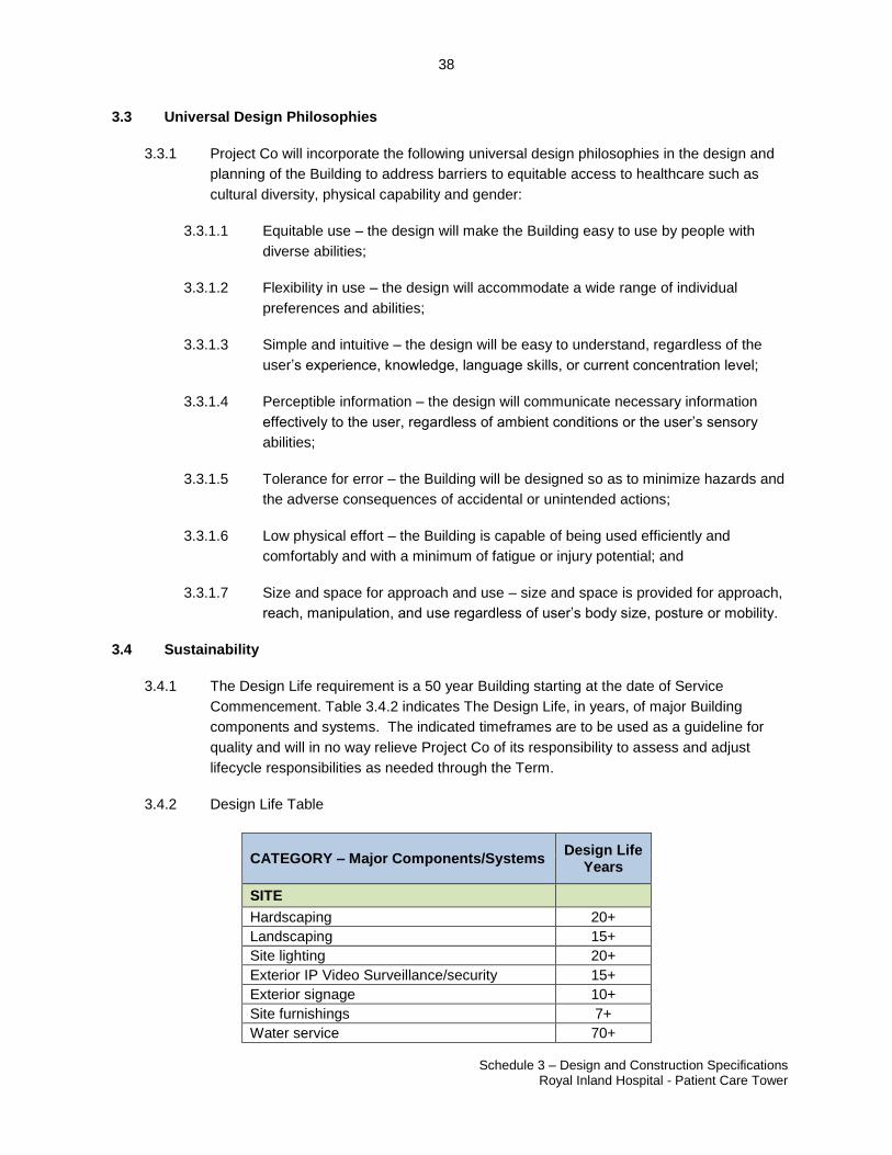
38
Schedule 3 – Design and Construction Specifications Royal Inland Hospital - Patient Care Tower
23507060.2
3.3 Universal Design Philosophies
3.3.1 Project Co will incorporate the following universal design philosophies in the design and
planning of the Building to address barriers to equitable access to healthcare such as
cultural diversity, physical capability and gender:
3.3.1.1 Equitable use – the design will make the Building easy to use by people with
diverse abilities;
3.3.1.2 Flexibility in use – the design will accommodate a wide range of individual
preferences and abilities;
3.3.1.3 Simple and intuitive – the design will be easy to understand, regardless of the
user’s experience, knowledge, language skills, or current concentration level;
3.3.1.4 Perceptible information – the design will communicate necessary information
effectively to the user, regardless of ambient conditions or the user’s sensory
abilities;
3.3.1.5 Tolerance for error – the Building will be designed so as to minimize hazards and
the adverse consequences of accidental or unintended actions;
3.3.1.6 Low physical effort – the Building is capable of being used efficiently and
comfortably and with a minimum of fatigue or injury potential; and
3.3.1.7 Size and space for approach and use – size and space is provided for approach,
reach, manipulation, and use regardless of user’s body size, posture or mobility.
3.4 Sustainability
3.4.1 The Design Life requirement is a 50 year Building starting at the date of Service
Commencement. Table 3.4.2 indicates The Design Life, in years, of major Building
components and systems. The indicated timeframes are to be used as a guideline for
quality and will in no way relieve Project Co of its responsibility to assess and adjust
lifecycle responsibilities as needed through the Term.
3.4.2 Design Life Table
CATEGORY – Major Components/Systems Design Life
Years
SITE
Hardscaping 20+
Landscaping 15+
Site lighting 20+
Exterior IP Video Surveillance/security 15+
Exterior signage 10+
Site furnishings 7+
Water service 70+
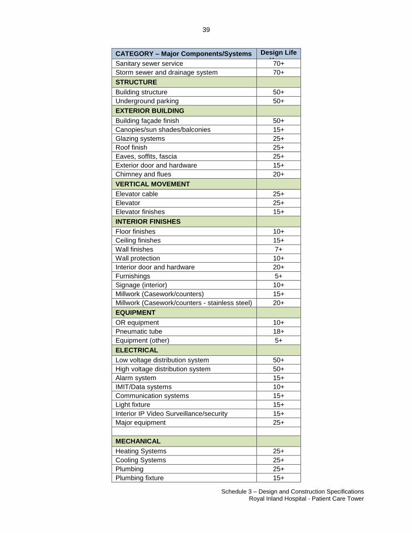
39
Schedule 3 – Design and Construction Specifications Royal Inland Hospital - Patient Care Tower
23507060.2
CATEGORY – Major Components/Systems Design Life Years
Sanitary sewer service 70+
Storm sewer and drainage system 70+
STRUCTURE
Building structure 50+
Underground parking 50+
EXTERIOR BUILDING
Building façade finish 50+
Canopies/sun shades/balconies 15+
Glazing systems 25+
Roof finish 25+
Eaves, soffits, fascia 25+
Exterior door and hardware 15+
Chimney and flues 20+
VERTICAL MOVEMENT
Elevator cable 25+
Elevator 25+
Elevator finishes 15+
INTERIOR FINISHES
Floor finishes 10+
Ceiling finishes 15+
Wall finishes 7+
Wall protection 10+
Interior door and hardware 20+
Furnishings 5+
Signage (interior) 10+
Millwork (Casework/counters) 15+
Millwork (Casework/counters - stainless steel) 20+
EQUIPMENT
OR equipment 10+
Pneumatic tube 18+
Equipment (other) 5+
ELECTRICAL
Low voltage distribution system 50+
High voltage distribution system 50+
Alarm system 15+
IMIT/Data systems 10+
Communication systems 15+
Light fixture 15+
Interior IP Video Surveillance/security 15+
Major equipment 25+
MECHANICAL
Heating Systems 25+
Cooling Systems 25+
Plumbing 25+
Plumbing fixture 15+
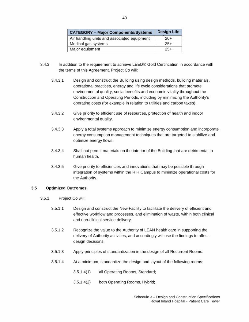
40
Schedule 3 – Design and Construction Specifications Royal Inland Hospital - Patient Care Tower
23507060.2
CATEGORY – Major Components/Systems Design Life Years
Air handling units and associated equipment 20+
Medical gas systems 25+
Major equipment 25+
3.4.3 In addition to the requirement to achieve LEED® Gold Certification in accordance with
the terms of this Agreement, Project Co will:
3.4.3.1 Design and construct the Building using design methods, building materials,
operational practices, energy and life cycle considerations that promote
environmental quality, social benefits and economic vitality throughout the
Construction and Operating Periods, including by minimizing the Authority’s
operating costs (for example in relation to utilities and carbon taxes).
3.4.3.2 Give priority to efficient use of resources, protection of health and indoor
environmental quality.
3.4.3.3 Apply a total systems approach to minimize energy consumption and incorporate
energy consumption management techniques that are targeted to stabilize and
optimize energy flows.
3.4.3.4 Shall not permit materials on the interior of the Building that are detrimental to
human health.
3.4.3.5 Give priority to efficiencies and innovations that may be possible through
integration of systems within the RIH Campus to minimize operational costs for
the Authority.
3.5 Optimized Outcomes
3.5.1 Project Co will:
3.5.1.1 Design and construct the New Facility to facilitate the delivery of efficient and
effective workflow and processes, and elimination of waste, within both clinical
and non-clinical service delivery.
3.5.1.2 Recognize the value to the Authority of LEAN health care in supporting the
delivery of Authority activities, and accordingly will use the findings to affect
design decisions.
3.5.1.3 Apply principles of standardization in the design of all Recurrent Rooms.
3.5.1.4 At a minimum, standardize the design and layout of the following rooms:
3.5.1.4(1) all Operating Rooms, Standard;
3.5.1.4(2) both Operating Rooms, Hybrid;
41
Schedule 3 – Design and Construction Specifications Royal Inland Hospital - Patient Care Tower
23507060.2
3.5.1.4(3) Utility Rooms, Soiled;
3.5.1.4(4) All Inpatient Bedrooms, including LDR; and
3.5.1.4(5) Neonatal Intensive Care Unit Private Bassinette Rooms.
3.5.1.5 Items to be standardized in their design and layout include: location of entry
points, room dimensions and aspect ratio, sinks or other plumbing fixtures,
medical gases, Millwork , and services. Apply standardization by using repetition
of room layouts and features to reduce errors and improve quality of service
delivery. Mirrored inpatient rooms including LDR will be considered standardized.
3.5.1.6 Design workplaces to support innovative and collaborative methods of working
(such as team approach to care, family centred rounds, huddles and daily
management systems) help incorporate the Authority’s new and emerging
technologies, incorporation of clinical research into daily methods of working,
respond to diverse work styles (such as hoteling and job-sharing), and optimize
flexibility and space utilization. A key element to the development of an
integrated workplace is the provision of physical environments that support
varied workplace strategies. Accordingly, Project Co will design workplaces to:
3.5.1.6(1) include modular, generic, acuity adaptable rooms and spaces;
3.5.1.6(2) provide floor lay-outs that accommodate teams as well as
individuals, and that support mobile employees who require
flexibility and use portable technology; and
3.5.1.6(3) consider co-location options, space saving strategies, lay-outs and
Systems Furniture that facilitate change; reduction in Schedule 3
requirements are to be agreed to by the Authority.
3.6 Adaptability, Flexibility and Expansion
3.6.1 Project Co will design and construct the New Facility:
3.6.1.1 so that it can accommodate the rapid cycle of innovation and change to support
development and implementation of new clinical and non-clinical work processes
and technology change;
3.6.1.2 to accommodate program, service, work and equipment change with minimized
utility infrastructure and New Facility impact, including down time, and so that
Clinical Spaces are acuity adaptable;
3.6.1.3 to support Future Expansion of Components, and capacity as a whole, including
planning zones for growth, loose fit design to optimize functionality within a given
floor area, and multi-use adaptable space;
3.6.1.4 with an infrastructure that incorporates excess systems capacity and includes
systems and components that support Future Expansion with minimized
42
Schedule 3 – Design and Construction Specifications Royal Inland Hospital - Patient Care Tower
23507060.2
disruption and allows for upgrades in Authority technology or technological
progression; and
3.6.1.5 to accommodate connections to a future development to the south of the New
Facility on the existing Alumnae Tower site.
43
Schedule 3 – Design and Construction Specifications Royal Inland Hospital - Patient Care Tower
23507060.2
PART 4. SITE DEVELOPMENT REQUIREMENTS
4.1 Site Considerations
4.1.1 While a prototype approach to the design for a health care building is desirable, tailoring
prototypes to the specifics of an existing site is critical for the success of the design.
Accordingly, Project Co will consider existing site constraints, infrastructure, unique
context and site-specific master planning for adaptation of any desirable prototypes.
4.1.2 Project Co will design the Building as an integrated part of the RIH Campus, and
accordingly:
4.1.2.1 Facilitate the delivery of clinical and non-clinical support services across the RIH
Campus through the provision of efficient physical links to existing RIH buildings;
4.1.2.2 Consider all new and existing occupant loading, exiting, and fire separation
requirements at all new combined linked connections;
4.1.2.3 Integrate effectively with existing RIH Campus communication and Life Safety
Equipment;
4.1.2.4 Consider the width and overhead clearance underneath the North Wing
breezeway for vehicular access flows;
4.1.2.5 Consider the existing topography of the RIH Campus and locates entrances and
access points to minimize slopes and promote accessibility;
4.1.2.6 Consider the vehicle flow and access point to the Clinical Services Building and
does not negatively impact existing access;
4.1.2.7 Consider the existing public transit routes on the Site and does not negatively
impact existing access;
4.1.2.8 Provide a distinctive architectural character, reflecting the Authority’s values and
role as a regional acute care centre and tertiary medical teaching centre for
health in the region and community; and
4.1.2.9 Support community access and include a highly visible main entry and lobby
along the RIH Campus ring road designed with high profile architectural scale
and features. The main entry and lobby will have a connection to the
underground parking and serve as the main entry point to the New Facility for
patients, visitors and staff. The existing main entrance at RIH will be maintained
and is anticipated to serve primarily the Future Expansion of the emergency
department. The main entrance shall be a landmark that intuitively draws visitors
from a distance with architectural cues, landscaping, lighting and signage.
4.1.3 Project Co will consider all design decisions within the context of enhancing the RIH
Campus.
44
Schedule 3 – Design and Construction Specifications Royal Inland Hospital - Patient Care Tower
23507060.2
4.2 Site Preparation - Demolition
4.2.1 Project Co is responsible for all abatement, containment, disposal of Hazardous
Substances and removal of all Hazardous Substances as part of their Design and
Construction scope of work.
4.2.2 Hazardous Substance Reports of the Hospital have been prepared for the Authority and
copies are available in the Data Room. Project Co acknowledges receipt of the
Hazardous Substance Reports.
4.2.3 Project Co is responsible for, as Project Co Hazardous Substances, all Hazardous
Substances disclosed in or reasonably inferred from the Hazardous Substance Reports,
in or under the RIH Campus and affected by or impacted by the Design and Construction.
4.2.4 Project Co is responsible for assessing and confirming the presence of any suspected
Hazardous Substances on, in or under the RIH Campus prior to proceeding with any
Design and Construction and any failure to do so is at Project Co’s risk.
4.2.5 If suspected Hazardous Substances are discovered during the Design and Construction,
Project Co will be responsible for completing a hazardous material study, at its cost, to
determine the extent of existing Hazardous Substances, including: asbestos, lead paint,
PCB’s and mercury.
4.2.6 Demolition includes demolition and removal of all materials from the RIH campus for all
material required to construct the New Facility, such as foundations, utilities, utility poles,
transformers, underground tanks, slabs, pits, sumps, pipes, cables, conductors, concrete
encasements, ducts, walls, fencing, railings, stairways, lamp standards, curbing, asphalt,
sidewalks, wheel stops, vaults, signs, landscape, waste excavation, clearing, grubbing,
pavement markings, and all other above ground or sub-surface material, prior to
constructing the New Facility. Demolition includes disconnecting and capping utilities.
Demolition includes landfill tipping fees.
4.2.7 Project Co's design will determine where the New Facility and existing RIH Campus
Buildings are joined as interior space. The New Facility is required to connect to the
existing Hospital on each of the following levels; Level 0, Level 1, Level 2 and Level 4;
refer to 4.4 Connections to Existing Hospital and Site Services. Connection at Level 3
between the New Facility Maternal and Child Health Services Component and the Level
3N future Pediatric area and existing Hospital elevator core is desirable. Connections are
to align with the network of existing Hospital corridors. Connections will permit safe and
efficient flow of patients, staff, services and public.
4.2.8 Project Co shall be responsible for completing the circulation path at all link connections
between the New Facility and existing Hospital; including extending the link to nearest
existing circulation corridor.
4.2.9 Project Co shall Make Good the existing Hospital at all link connections.
45
Schedule 3 – Design and Construction Specifications Royal Inland Hospital - Patient Care Tower
23507060.2
4.2.10 Project Co shall not create dead end corridors conditions or cause the Authority to incur
any costs in completing functional link connections to the existing Hospital.
4.2.11 Project Co will be responsible for any required modifications to existing exterior walls
including infill of existing exterior windows which shall meet all the requirements of
Schedule 3.
4.2.12 The New Facility ventilation system will replace the existing located on the roof of Level 3
North Tower (east side). Provide all required temporary connections and phasing to
maintain existing MDR operation during the construction. Project Co shall remove all
redundant equipment, piping, and ductwork from the Site, provide new roofing system
and Make Good all assemblies affected.
4.2.13 Design and construct a new concrete trash enclosure pad for St. Ann’s Academy as
needed. Coordinate the relocation with the Authority. The concrete pad design shall be
designed to the same structural standard as the existing or better.
4.2.14 The walls separating the New Facility construction site from remaining structures will be
designed so that the demolition and construction activities of the New Facility shall not
interfere with the normal operation of the RIH Campus including buildings, roads and
services.
4.2.15 Obtain City of Kamloops and other Authority approvals required to undertake any
demolition.
4.2.16 Make provisions to ensure that affected areas of the remaining Hospital are weather-
proof during and after demolition and for the duration of construction of the New Facility.
4.2.17 Terminate existing surfaces at structures to be demolished along straight lines at natural
divisions determined through consultation with and approval by the Authority. Cut existing
surfaces so that a smooth transition with the New Facility will result; conform to
applicable codes for demolition of structures and provide for the safety of adjacent
structures, the erection and maintenance of temporary barriers and security devices, dust
control, runoff control and disposal of materials.
4.2.18 Be responsible for ensuring that fire safety will be in force at all times during demolition.
4.2.19 Provide dust control at all times:
4.2.19.1 spray demolition area with water once demolition of structure begins;
4.2.19.2 manage water runoff through the RIH Campus;
4.2.19.3 protect City storm drains.
4.2.20 Avoid use of jack hammers; instead, concrete chipping hammers are preferred and can
be employed, refer to Schedule 2 Section 6.18 and 6.19 Control of Noise and Vibration.
46
Schedule 3 – Design and Construction Specifications Royal Inland Hospital - Patient Care Tower
23507060.2
4.2.21 Carry out demolition activities so as not to interfere with access to exiting RIH Campus
buildings. Requirements for traffic control shall be coordinated with the Authority.
4.2.22 Provide overhead protection from falling debris.
4.2.23 Provide perimeter screen and safety walls to ensure safety and protection of people and
objects outside of the demolition area.
4.2.24 Schedule, hours of operation and traffic required for demolition determined in
consultation with the Authority as per Schedule 2 Design and Construction Protocols.
4.2.25 Never leave demolition and demolition equipment in precarious, unsafe or hazardous
condition at the end the work day.
4.2.26 Secure demolition site 24/7; obtain Authority’s approval of Project Co’s security plan prior
to commencing work.
4.2.27 Coordinate the demolition schedule with existing Authority construction on the RIH
Campus.
4.2.28 Conform to applicable regulatory procedures, including WorkSafe BC requirements,
during all phases of the demolition and when discovering hazardous or contaminated
materials.
4.2.29 If any buried tanks are discovered, surrounding soils shall be tested for contamination.
4.2.30 Provide required LEED® documentation for recycled content.
4.2.31 Accurately record actual locations of capped utilities, subsurface obstructions and/or
conditions.
4.3 Urban Design and Site Development
4.3.1 General
4.3.1.1 Minimize the impact of site development and Building placement on adjacent
neighbours and land uses. Preserve visual privacy and sunlight for adjacent
properties and buildings, and include features that will give the Building an
identity consistent with its overall urban context.
4.3.1.2 Consider the micro-climatic effects arising from the location and configuration of
parking, walkways and other Site buildings, including effects of Building entrance
orientation on patient, staff and visitor comfort and safety. Consider the existing
slope across the RIH Campus and its impact on RIH Campus circulation, New
Facility location and configuration.
4.3.1.3 Articulate the exterior of the Building to create an architecturally interesting and
refined structure. Consider emphasizing the modular requirements of the
47
Schedule 3 – Design and Construction Specifications Royal Inland Hospital - Patient Care Tower
23507060.2
program in the massing and materials to achieve articulation, visual interest, and
human scale.
4.3.1.4 Contribute to an urban, pedestrian-oriented RIH Campus environment by
creating a fine-grained road/pedestrian/open space network that contributes to
smaller, human-scaled spaces and increased access/permeability. The RIH
Campus is built on a relatively steep site. Confirm and illustrate that all road and
pedestrian routes are graded to accessible slope standards.
4.3.1.5 Reinforce the physical relation of the Building with the RIH Campus ring road and
the Clinical Services Building and create a legible RIH Campus layout and
pattern to foster a strong sense of place and identity.
4.3.1.6 Provide site furniture and pedestrian scale lighting to complement the existing
RIH Campus furniture and lighting.
4.3.1.7 Design for the functional separation of traffic for: 1) emergency vehicles, 2)
visitor/ staff vehicles, 3) Medi-Van / HandyDART vehicles, 4) public transit, and
5) service vehicles.
4.3.1.8 Integrate vehicular circulation with layout of pedestrian and bicycle zones to
provide visible connections, promote safe travel, and to minimize conflict
between vehicles and other modes of travel. Design the driveways to provide
connections between the surrounding roads and the main entrance to the
Building.
4.3.1.9 Design for maximum access to the New Facility. Provide separate and distinct
passenger-side lay-by stall drop-off areas. All drop-off areas will be covered with
canopies or a porte cochere to provide shelter for staff and visitors getting in and
out of vehicles, including Medi-Van/ HandyDART. Provide protection from
inclement weather along the entire length of the drop-off and pick-up area.
4.3.1.10 Include waiting space and benches for seated, in-wheelchair and standing users;
4.3.1.11 Provide secure bicycle storage area. Quantity of secure bicycle storage shall
meet both City of Kamloops Bylaw and LEED® requirements. Bicycle racks for
visitors shall be located in a convenient, well-lit location that is easily accessible
by visitors and shall be placed so as not to obstruct pedestrian circulation. In
addition, Project Co shall provide new secure bicycle storage area, fenced with
card reader access gate, for 20 bicycles to replace the existing Hospital secure
bicycle storage area located within the Site (within the east parking lot). All
secure bicycle storage shall be covered and protected from the elements,
including covers which project over gates or access points.
4.3.1.12 Provide safe pedestrian refuge spaces behind sidewalk wheelchair ramps.
4.3.1.13 Keep existing supply flows to the existing loading docks and loading areas intact
during and after construction.
48
Schedule 3 – Design and Construction Specifications Royal Inland Hospital - Patient Care Tower
23507060.2
4.3.1.14 Maintain existing access to and between ED department and existing Heliport at
all times. Maintain the existing Heliport H1 and H3 flight paths and obstacle
limitation surfaces at all times.
4.3.1.15 Design refuse, recycling, and utility areas so they cannot be viewed from the
surrounding buildings or neighbourhood areas.
4.3.1.16 Reduce the visual impacts of Westland Parking area, providing plant shrubs and
small trees to define circulation routes for pedestrians and vehicles.
4.3.1.17 Incorporate sustainable measures such as integrated landscaping, drainage
swales, or permeable paving to decrease storm water run-off.
4.3.1.18 Create meaningful open spaces, both urban and natural, for the benefit of visitors
and staff which provide opportunities for recreation and healing and contribute to
a cohesive, healthy community; capitalize on opportunities for outdoor areas of
respite and repose to aid in providing a healing environment.
4.3.2 Public Realm and Open Space
4.3.2.1 Design and construct the Building with consideration for the legibility, quality and
consistency of the overall treatment of the public realm, including public open
space, pedestrian corridors and streets, to achieve the urban design objective for
a unified and attractive built environment. Provide a thoughtful integration with
the RIH Campus and the surrounding natural slopes.
4.3.2.2 Provide a design that responds to CPTED principles having particular regard for
theft, mischief and vandalism.
4.3.3 RIH Campus Wayfinding and Exterior Signage
4.3.3.1 Arrange pedestrian pathways created by the New Facility to ease Wayfinding
and create an amenable environment for pedestrians through the use of
coordinated methods of Wayfinding which inform people of routes through the
RIH Campus to specific buildings and entries or to the major street and transit
nodes. Encourage pedestrians to avoid unsafe vehicle roads by providing well-
signed alternative pedestrian routes. Utilize paving patterns which can easily be
differentiated from vehicular paving by pedestrians where they cross vehicular
traffic.
4.3.3.2 Provide visually connected pathways and integrated outdoor amenity spaces with
required signage.
4.3.3.3 Provide external directional signage that:
4.3.3.3(1) clearly identifies the Building and its Components including the
Main entrance, drop-off areas and all parking areas;
49
Schedule 3 – Design and Construction Specifications Royal Inland Hospital - Patient Care Tower
23507060.2
4.3.3.3(2) is easily understandable by patients and families using it to access
the RIH Campus for first time;
4.3.3.3(3) clearly indicates the entry point(s) to the RIH Campus, access
points for public parking, lay-by drop-off locations, entry points to
the RIH Campus buildings and where there are multiple entrances,
signs clearly identify which entrances are for which purpose, any
restrictions for both entry and/or parking for various vehicle types
and any ‘after-hours’ access limitations;
4.3.3.3(4) is well-illuminated, backlit, reflective or high contrast and easily
visible at night;
4.3.3.3(5) minimizes light spillage;
4.3.3.3(6) uses universal symbols and standard colours for parking signage;
4.3.3.3(7) uses the Interior Health Graphic Standard for all ‘Interior Health
and logo’ placement;
4.3.3.3(8) resists wind loads as required by the BC Building Code, latest
edition;
4.3.3.3(9) uses solar power, which is encouraged by the Authority. Provide
solar panels which can be mounted with the signage or remotely
positioned as required. Provide LED fixtures with light colour
spectrum to be confirmed in consultation with the Authority.
4.3.3.4 Provide all necessary exterior illuminated signage along Columbia Street, the
RIH Campus ring road and 3rd
Avenue, identifying the New Facility and the
access points. Signage shall be legible for drivers at an adequate distance that
they can safely slow down and enter the RIH Campus for drop-off and parking
areas. Fully coordinate way-finding and signage with the Authority and the RIH
Campus.
4.3.3.5 Provide all temporary site signage required prior to and during construction to
notify public and staff regarding the following:
4.3.3.5(1) Vehicles – public, service and staff vehicle route changes.
4.3.3.5(2) Walkways, sidewalks – public and staff closure, alternate routes
locations, access
4.3.3.5(3) Site and Building access/egress – temporary closure of access or
egress from any of the building on the RIH Campus
4.3.3.5(4) Hours of closure – temporary hour changes
50
Schedule 3 – Design and Construction Specifications Royal Inland Hospital - Patient Care Tower
23507060.2
4.3.3.5(5) Relocated parking, drop-offs/pick-ups – temporary relocation of
parking, drop-off pick-up stalls for public, taxi, ambulance, etc.
4.3.4 Site Access for Disabled, Elderly and Paediatric Populations
4.3.4.1 The primary pedestrian systems, public open spaces, primary private walkways
and principal entrances to the Building will be accessible to the physically
challenged. The design shall exceed disability access guidelines in terms of
wheelchair use as these are written for independent wheelchair users and not
those requiring physical assistance with wheeled mobility.
4.3.4.2 Provide adequate space at drop off and pick up points for additional assistive
equipment.
4.3.4.3 Access, egress routes, entrances and all exterior courtyards, gardens, patios or
similar outdoor amenity spaces will be accessible for persons requiring assistive
mobility equipment (including strollers).
4.3.4.4 Use signage, markers, or other levels of Wayfinding along access routes to
indicate to the physically challenged the route terminus points or any required
route changes to ensure universal access throughout the RIH Campus.
4.3.5 Site Lighting
4.3.5.1 Provide lighting to enable 24 hour per day public and staff accessibility.
4.3.5.2 Provide lighting for public outdoor spaces to create an unobtrusive, human scale
lighting concept, with a hierarchy of fixture types designed according to functional
and security needs (including CPTED), and reflecting the hierarchy of pedestrian
corridors.
4.3.5.3 Light fixtures within the reach of pedestrians will be vandal-proof.
4.3.5.4 Lighting on pedestrian paths will illuminate not just the path but also spill over to
illuminate several metres adjacent to the path, particularly enroute to transit
connections.
4.3.5.5 Provide lighting for roadways, walkways and parking areas within the Site to
ensure safe vehicle and pedestrian traffic with respect to collisions, personal
safety, and building access and egress. Lighting design considerations should
address existing RIH buildings and neighbours privacy from all storeys.
4.3.5.5(1) Prevent light trespass into patient rooms and neighbouring yards
and windows.
4.3.5.5(2) Prevent lighting glare, shadow or high contrast with surrounding
areas
51
Schedule 3 – Design and Construction Specifications Royal Inland Hospital - Patient Care Tower
23507060.2
4.3.5.5(3) Screen views into patient rooms and neighbouring yard from upper
floor windows.
4.3.5.6 Site lighting will conform to LEED® light spillage requirements and shall comply
with CSA and City of Kamloops Standards complete with sharp cut-off (dark sky
compliant) to meet LEED Certification. Match existing lamp sources on the street.
4.3.5.7 Replace parking lot lighting for the St. Ann’s Academy where existing is
demolished.
4.3.5.8 Establish a safe pedestrian route with appropriate lighting from all areas of the
proposed Westland Parking site.
4.3.6 Landscaping
4.3.6.1 Provide landscaping for the Site that contributes to the creation of a livable,
healthy and responsive community.
4.3.6.2 Create a landscape environment that is a sympathetic integration between the
urban RIH Campus and the surrounding natural slopes and adjacent
developments.
4.3.6.3 Locate trees, shrubs, lighting and seating elements to support Wayfinding on the
RIH Campus and to provide comfortable waiting areas at the Building entrances.
4.3.6.4 Provide outdoor amenity areas, with covered portions for protection from the
elements that provide for respite and repose dedicated to patient and family use
as follows:
4.3.6.4(1) Minimum 290 NSM at Level 1 with Convenient Access to the New
Facility main entrance and Retail Coffee Shop and accessible from
the main entrance area.
4.3.6.5 Provide outdoor amenity areas, with covered portions for protection from the
elements that provide for respite and repose dedicated to staff only use as
follows:
4.3.6.5(1) Minimum 150 NSM total area, distributed within the New Facility
and accessible from Back of House or Restricted Circulation.
Authority’s preference is to consolidate the total area of outdoor
staff amenity space within no more than three designated areas
which can be on different levels of the New Facility. The outdoor
staff amenity spaces shall have Convenient Access from Staff
Rooms. Outdoor amenity areas shall not be smaller than 20sm or
located at grade. Outdoor amenity areas shall be designed to
provide views of the surrounding area from above and contain
glazed guardrails to maximize views.
52
Schedule 3 – Design and Construction Specifications Royal Inland Hospital - Patient Care Tower
23507060.2
4.3.6.6 Provide landscaping complementary to any permanent landscaping at RIH
Campus to create a contiguous and unified landscape buffer. Street trees will be
a consistent species and be suitable to Site conditions. Provide tree trench
planting details where possible in street boulevards and in hard surface courtyard
conditions.
4.3.6.7 All landscaping and site design will comply with all applicable City of Kamloops
bylaws.
4.3.6.8 Use large calliper deciduous trees and evergreen trees that provide seasonal
interest in association with ground cover plants and low shrub plantings. Use a
variety of plant material to reflect seasonal change.
4.3.6.9 Limit the number of tree species where appropriate to help unify the Site
character, create recognizable spaces, contribute to RIH Campus orientation and
create a strong sense of place.
4.3.6.10 Use indigenous flora where appropriate to minimize maintenance and reduce
water requirements. All plant selection to be suitable for the Kamloops plant
hardiness zone and specific to the Site micro-climate conditions.
4.3.6.11 Landscape open spaces and setbacks, including protecting all existing heritage
trees, as required by the City of Kamloops. Provide suitable protection in the form
of fencing around existing street trees to be retained. Protected zone should
extend to the drip line of the tree canopy. Provide a separate tree protection plan
illustrating the species and size of all the trees on Site and within 10 metres of
the limit of construction. Also indicate the trees to be removed, the trees to be
retained, the protection measures to be kept in place for the duration of the
contract and any other requirements of the Authority Having Jurisdiction.
4.3.6.12 Provide all landscaping for the outdoor amenity areas. Include all site furnishings
and art work to complete the space. Provide elements such as sculpture,
labyrinth, healing gardens, raised garden plots and a variety of seating spaces to
create distinct zones of use within the courtyards and perimeter areas. Water
features are not to be considered. Plant selection shall consist of non-poisonous
species. All elements shall be designed to be appropriate to the specific needs of
the users and be universally accessible.
4.3.6.13 Provide pedestrian surfaces that are suitable for use by wheelchairs, double wide
strollers, and small wheeled medical devices. Asphalt, wide expanses of pavers
or crushed rock surfaces will not be permitted for outdoor amenity areas
surfaces. Concrete pavers shall be colored, contain special aggregates and/or
architectural finishes to enhance their appearance and be used in combination
with built in furniture or landscape features to break up wide expanses. Use
concrete pavers in varying patterns and textures to provide visual interest.
4.3.6.14 Landscape Plans to include all exterior features of other disciplines such as
lighting, retaining walls, architectural columns and utility infrastructure
53
Schedule 3 – Design and Construction Specifications Royal Inland Hospital - Patient Care Tower
23507060.2
components. Landscape design to incorporate the design requirements of these
existing and proposed exterior and underground items.
4.3.6.15 Use flowering and non-edible fruit producing trees to promote natural avian
habitat. Avoid fruit-producing trees in hard surface and patio areas.
4.3.6.16 Group plants of similar habits and environmental requirements to minimize the
use of water, chemicals and fossil fuel use for routine maintenance and to
promote a healthy local ecosystem using sustainable measures.
4.3.6.17 Unify the ground plane treatment through the use of common paving materials,
tree grates, lighting and other landscape furniture items. Clearly show the
installation and construction details for the integration of these various elements.
4.3.6.18 Shrubbery within 2 m of walkways shall not exceed 50 cm in height.
4.3.6.19 Provide and coordinate design for exterior furniture, including benches provided
at regular intervals for ease of use particularly for the infirm. Select products on
the basis of safety, comfort, design and materials that relate to the Building
architecture and landscape design, durability and required maintenance.
Provide installation details for furniture in all specified surfaces.
4.3.6.20 Design landscape features and provide furniture that does not encourage the use
of skateboards.
4.3.6.21 Provide landscape features for the enjoyment of patients, visitors and staff;
provide the use of healing gardens and quiet spaces verses play features.
4.3.6.22 Where roof areas are directly visible from Hospital inpatient bedrooms, Staff
Rooms or lounges, consider extensive type green roofs in the New Facility.
Landscape plans to demonstrate details for construction, access requirements
for maintenance, water availability, irrigation methods, and the extent of
maintenance required. If used, all green roof areas to have low maintenance
requirements and be appropriate for the micro-climate of each roof area.
4.3.6.23 Provide a separate Landscape Grading Plan showing existing and proposed
contours. A plan for each area is required to identify all gradients on pedestrian
hard surface areas and landscape areas. Surface drainage requirements and
proposed elevations to be coordinated with other disciplines. Clearly show the
limit of construction and blend proposed grades into the existing slopes. This is
especially critical on the steep slopes surrounding the Westland site.
4.3.6.24 If required, design leveling strips at the point of access to the Building to ensure
ongoing barrier free access. The leveling strips should be designed to be barrier
free and paved and allow for simple adjustment if required by Building
settlement.
54
Schedule 3 – Design and Construction Specifications Royal Inland Hospital - Patient Care Tower
23507060.2
4.3.6.25 All retaining walls and constructed slopes to be clearly identified and referenced
on the Landscape Grading Plan, complete with top and bottom elevations. All
elevations to be coordinated with the project design of the other disciplines.
Prepare sections to illustrate the landscape integration with all exterior structures.
4.3.6.26 Minimize grade changes for drop curbs and raised crossings. Drop curbs aligned
to pedestrian crossings to include flat area separate from sloped portions to
provide wheelchair area of refuge from traffic.
4.3.6.27 All external foliage will be reviewed by site security /violence intervention
program to ensure it does not interfere with exterior camera views and any
required external site lines.
4.3.6.28 Provide landscaping for the Westland Parking as per the City of Kamloops’
bylaw. Calculations for the existing tree removal and the required tree
replacement to be the responsibility of Project Co. Demonstrate the provision of
shade and landscape within the parking area. Careful consideration is required
for the integration of the surrounding natural landscape on the steep slopes with
the proposed landscape and surface drainage requirements of the Westland
Parking site. Landscape sections are required to illustrate the landscape
installation with the adjacent existing facilities and proposed structures.
4.3.6.29 At the Westland Parking site document the existing playground area and
apparatus of the existing day care site. Project Co is responsible for
reinstatement of the playground adjacent to the existing day care. The
playground design is to satisfy the requirement of the day care facility and Project
Co shall coordinate this design with the day care administration and the
Authority. This includes the relocation or replacement of sheds and storage
structures. The playground design to be universally accessible. The design to
specifically address the unique grading and drainage requirements of the Site
and the modifications required to integrate the playground with the day care and
the parking lot design. Project Co phasing plan to coordinate the availability of
outdoor use for the day care facility.
4.3.6.30 Irrigation. Design irrigation system to provide automatic, timed irrigation for all
soft landscape areas at the Westland Parking and New Facility. Incorporate
efficient, low water-use landscape design where practical and appropriate,
utilizing harvested water if possible. Connect new systems to existing irrigation
system if feasible. Irrigation system to comply with the Irrigation Industry
Association of B.C’s “Standards for Landscape Irrigation Systems”.
4.3.6.31 Maintenance: Delineate the extents of the different levels of landscape
maintenance requirements for establishment and continued sustainability of this
project. Provide a landscape design with low maintenance requirements where
practical and appropriate. However, the landscape maintenance requirements
will vary from the high-use building courtyards to the re-establishment of the
surrounding native vegetation slopes.
55
Schedule 3 – Design and Construction Specifications Royal Inland Hospital - Patient Care Tower
23507060.2
4.3.7 Parking and Site Access
4.3.7.1 Off-Site Works – Design and construct sidewalks, as per the City of Kamloops’
bylaws, on 3rd
Avenue where shown on the site services drawing in Appendix 3G
Site Services.
4.3.7.2 On-Site Works – Design and construct permanent parking for the New Facility,
including:
4.3.7.2(1) All parking stalls, underground and surface, shall be sized per the
City of Kamloops bylaw requirements. The ratio of small and large
stalls shall be per the City of Kamloops bylaw requirements. The
minimum vertical clearance above each stall shall be 2.4m unless
required to be higher by the Authority Having Jurisdiction;
4.3.7.2(2) Provide a minimum of 201 parking stalls as follows (disability
parking spaces will count as one stall only):
4.3.7.2(2)(a) Underground parking (below the New Facility) –
minimum 44 stalls;
4.3.7.2(2)(b) Westland Parking – minimum 157 stalls.
4.3.7.2(3) The minimum number of disability parking spaces and small car
spaces for the Westland Parking will be as per the City of
Kamloops’ bylaw. Provide 4 disability parking spaces in the
underground parking below the New Facility.
4.3.7.2(4) The Authority will secure temporary off-site parking for the
displaced stalls in the east physician parking lot during the
construction period of the Westland Parking areas;
4.3.7.2(5) Design and construct a safe pedestrian crossing from the
Westland Parking across the RIH Campus ring road to meet the
current Pedestrian Crossing Control Manual for British Columbia
standards and guidelines;
4.3.7.2(6) Set parking layouts in an orderly and logical design to minimize
confusion and excessive internal circulation;
4.3.7.2(7) Apply CPTED principles, including the following:
4.3.7.2(7)(a) reduce opportunities for graffiti through the use anti-
graffiti coatings; at a minimum provide anti-graffiti
coating on the exterior, and
4.3.7.2(7)(b) reduce opportunities for hiding spaces.
56
Schedule 3 – Design and Construction Specifications Royal Inland Hospital - Patient Care Tower
23507060.2
4.3.7.2(8) Provide a method for users to readily summon help if in distress or
danger in both exterior parking areas and in the underground
parking.
4.3.7.2(9) Provide parking payment machines at a minimum in the following
locations:
4.3.7.2(9)(a) Minimum 2 parking payment machines; one per floor
in the underground parking;
4.3.7.2(9)(b) Minimum 2 parking payment machines in the main
lobby; and
4.3.7.2(9)(c) Minimum 2 parking payment machines at the
Westland Parking.
4.3.7.2(10) Parking payment machines to be supplied by the Authority and
installed by Project Co. Location of the machines to be reviewed
by the Authority and placed to facilitate efficient payment by users
without requiring back-tracking and return trips;
4.3.7.2(11) Locate parking payment machines in the underground parking
close to entrances to elevators;
4.3.7.2(12) Locate parking payment machines in the exterior parking areas
spread throughout the parking area to provide easy access, and
4.3.7.2(13) Design traffic flow which minimizes car speed on the RIH Campus
and provide traffic calming measures to slow cars down where
required to encourage safe traffic speed. Traffic calming measures
include landscape features, road textures and speed bumps.
4.3.7.3 Design and construct parking in accordance with the following:
4.3.7.3(1) Design and construct underground parking that is capable of being
secured and locked when not in use;
4.3.7.3(2) Provide adequate provision for ingress and egress to all parking
spaces to ensure ease of mobility, ample manoeuvring clearances,
and safety of vehicles and pedestrians;
4.3.7.3(3) Allow public and staff vehicles entering the RIH Campus from 3rd
Avenue to remain on the RIH Campus and access the New Facility
drop-off/pick-up area and underground parking with two-way traffic
circulation without having to leave the RIH Campus;
4.3.7.3(4) Provide fire vehicle access to the New Facility main entrance. Fire
vehicles cannot pass underneath the existing North Wing
breezeway;
57
Schedule 3 – Design and Construction Specifications Royal Inland Hospital - Patient Care Tower
23507060.2
4.3.7.3(5) Provide glazing between parking areas and exit stairs. Windows in
exit stair doors are to be provided in addition to windows in
demising walls and/or full height door sidelights;
4.3.7.3(6) Provide visual line of sight between parking areas and elevator
lobbies, stairwells and Building entrance points through glazed
vestibule entrance doors, windows and sidelights;
4.3.7.3(7) Ensure all parking areas are well lit; clearly and intuitively
numbered and marked with paint or signage, in coordination with
the New Facility Wayfinding;
4.3.7.3(8) Paint all stall lines and stall numbers. Stall numbers shall be
painted on the wall at a height visible to the driver when in the
vehicle;
4.3.7.3(9) Paint all underground parking interior walls and soffits white;
4.3.7.3(10) Provide bent steel plate protective covers painted yellow and
suitably fastened to adjacent substrate at the required height to
collect all vehicle bumpers at all exposed vertical rain water
leaders, other miscellaneous piping and fixtures as required to
protect from any potential vehicular impact damage throughout;
4.3.7.3(11) Provide concrete filled domed steel bollards painted yellow and
suitably fastened to adjacent substrate to protect overhead door
jambs, glazed screens and all fixtures within vehicular access as
required to protect from any potential vehicular impact damage
throughout;
4.3.7.3(12) Underground parking shall have a system of indicating that garage
is full. Provide a parking count system that identifies full or
available parking status for both public and staff parking stalls,
taking into account accessible stalls, for review and approval by
the Authority. System shall include LED signage located at
strategic points including both vehicle entrances to alert drivers to
the parking availability status. System shall be programmable and
flexible should the Authority make future changes to the ratio of
staff and public parking stalls by floor in the underground parking;
4.3.7.3(13) Use Wayfinding strategies, including signage, to allow each floor
and underground parking level to be identifiable and distinct to
assist in orientation and ease of finding/identifying parking stalls.
Acceptable Wayfinding strategies include use of symbols and a
continuous horizontal band of colour painted on the walls of
underground parking that make the parking level uniquely
identifiable. Coordinate width, height and location of stall numbers
with horizontal banding.
58
Schedule 3 – Design and Construction Specifications Royal Inland Hospital - Patient Care Tower
23507060.2
4.3.7.3(14) Use vehicle ramps that do not exceed recommended slope as per
City of Kamloops Parking By-Law;
4.3.7.3(15) Lay out parking such that it does not require a vehicle to back up
for more than 10m;
4.3.7.3(16) Maximum allowable slope or cross-fall is 5% applicable to both the
parking stalls and access aisles;
4.3.7.3(17) Provide motorcycle parking spaces complete with proper distinct
line painting and surface labelling, number of spaces to be
determined by the Authority through Schedule 2 Appendix 2C
Review Procedure;
4.3.7.3(18) All floors of the underground parking shall be contiguous. Vehicles
shall be able to access all floors of the underground parking
without having to leave the underground parking and re-enter.
4.3.7.4 On-Site Works - Design and construct lay-by and parking stalls for the Building,
including:
4.3.7.4(1) Lay-by stalls for passenger-side patient drop-off and pick-up only
located adjacent to the New Facility main entrance to
accommodate a minimum of 4 Medi-Van / HandyDART vehicles
and 4 cars (taxi, courier and visitor); the 4 Medi-Van / HandyDART
stalls shall all accommodate the larger of the two vehicles;
4.3.7.4(2) The terms “drop-off” and “pick-up” refer to quick turnover parking
spaces for which the Authority intends to limit the length of time
they are continuously occupied by the same vehicle. The layout of
these spaces shall meet all applicable City of Kamloops parking
space by-laws, including size.
4.3.7.4(3) Drop-off and pick-up spaces will be passenger-side lay-by, parallel
type spaces located adjacent to main entrance which provide
sufficient room for elderly and physically impaired visitors to
maneuver safely. Provide vertical clearance over all stalls and
vehicle paths in the drop-off and pick-up area to accommodate the
design vehicles including Ambulances for future flexibility;
4.3.7.4(4) The Authority’s anticipated HandyDART and MediVan vehicles
consists of the following, which are subject to change and shall be
confirmed by Project Co during the design phase:
4.3.7.4(4)(a) HandyDART vehicle: ARBOC. Dimensions are as
follows: 3.1m H x 8.5m L x 2.4m W. Vehicles have a
side ramp that extends 1.57m. Provide minimum
59
Schedule 3 – Design and Construction Specifications Royal Inland Hospital - Patient Care Tower
23507060.2
1200mm clearance for a person in a wheel chair to
get on and off the ramp;
4.3.7.4(4)(b) Medi-Van vehicle: Nissan NV. Dimensions are as
follows: 6.7m x 2.4m x 2.4m.
4.3.7.5 On-Site Works - Principles
4.3.7.5(1) do not obstruct the free flow of traffic in and out of the RIH Campus
or onto adjacent streets; and
4.3.7.5(2) provide adequate provision for ingress and egress to all spaces to
ensure ease of mobility, ample manoeuvring clearances, and
safety of vehicles and pedestrians.
4.4 Connections to Existing Hospital and Site Services
4.4.1 General
4.4.1.1 The Building will not function autonomously but instead will contribute to an
overall integrated RIH Campus. Accordingly, Project Co will design the Building
to maximize opportunities for connections to the existing RIH buildings and
enhance the ability for the Other Site Facilities and the New Facility to function in
a cohesive manner. In order to achieve this, Project Co shall design and
construct all links identified in this Schedule and the Project Agreement.
4.4.2 Connections for People and Materials
4.4.2.1 Design the New Facility to maintain and expand on the continuity of existing
General Circulation systems. The indicative link connections to existing Hospital
may be found in Schedule 2 Appendix 2I Renovation Work Area Diagrams,
Appendix 4B and the Indicative Design drawing package located in the Data
Room. Some link connections are to be designed and constructed as Phase 2
Renovation Services, refer to Appendix 4B for description and scope of work.
The connections to the New Facility are to align with the existing corridors.
Connections will be designed to provide for ease of visitors, staff, patient and
material transfers between New Facility and existing RIH Campus;
4.4.2.2 At a minimum, and in addition to any others required by Project Co to meet Code
exiting requirements, provide interior horizontal connections between the New
Facility and the existing Hospital as follows:
4.4.2.3 Level 0
4.4.2.3(1) One connection with Convenient Access to the exiting RIH elevator
core for transport of services and materials from the existing RIH
loading dock and RIH elevator core to the New Facility
Patient/Service Elevators and Materials Management areas, and
60
Schedule 3 – Design and Construction Specifications Royal Inland Hospital - Patient Care Tower
23507060.2
soiled returns from the MDR Cart Marshalling Soiled area to the
existing MDR soiled returns entry point;
4.4.2.3(2) One connection with Direct Access between the existing MDR OR
storage area to the New Facility Cart Marshalling – Sterile area for
the transport of sterile supplies to the New Facility sterile core via
the dedicated MDR clean elevator.
4.4.2.4 Level 1
4.4.2.4(1) One connection with Convenient Access to the exiting RIH elevator
core for visitors and staff to travel efficiently from the Main
Entrance and Lobby Component to the existing RIH elevator core.
Visitors arriving at the New Facility Entrance Vestibule will use the
existing RIH elevators to access the New Facility Level 4 Surgical
Services component and any existing RIH inpatient units through
Front of House circulation;
4.4.2.4(2) One connection with Convenient Access to the exiting Cafeteria
Annex area for safe and efficient transport of services from RIH to
the New Facility Patient/Service elevators through Back of House
circulation.
4.4.2.5 Level 2
4.4.2.5(1) One connection with Convenient Access to the exiting RIH elevator
core and existing Clinical Support Building link for visitors and staff
to travel efficiently and conveniently from existing RIH to the New
Facility public elevators through Front of House circulation;
4.4.2.5(2) One connection with Convenient Access to the Future Expansion
of the Emergency Department and western boundary of the
existing East Wing, for convenient transport of patients, staff and
services from the Emergency Department to the New Facility
Patient/Service elevators through Back of House circulation;
4.4.2.5(3) One connection with Convenient Access to the existing RIH
Laboratory for convenient transport of Laboratory staff and
services from the existing Laboratory to the New Facility
Patient/Service elevators through Back of House circulation.
4.4.2.6 Level 4
4.4.2.6(1) One connection with Convenient Access to the exiting RIH elevator
core for staff and pre-operative patients to travel safely and
efficiently from existing Level 4 West Daycare Surgery area to the
Surgical Services Component, and for staff and post-operative
patients to travel safely and efficiently from existing Level 4 North
61
Schedule 3 – Design and Construction Specifications Royal Inland Hospital - Patient Care Tower
23507060.2
Post Anesthetic Recovery Room (PARR) Area to the existing RIH
elevator core;
4.4.2.6(2) One connection with Direct Access between the existing Level 4
North PARR area to the Surgical Services Component for staff and
post-operative patients to travel safely and efficiently from the OR
to PARR;
4.4.2.6(3) One connection with Direct Access from the south wall of the
existing Level 4 North PARR area to the New Facility
Patient/Service elevators through Restricted Circulation for staff
and post-operative patients to travel safely and efficiently from
PARR to the New Facility inpatient floors.
4.4.2.7 The connections shall be distinct and physically separated to provide
independent continuity of public, patient and staff, equipment and material flows.
4.4.2.8 One connection at Level 3 is desirable with Convenient Access to the exiting RIH
elevator core and Level 3 North (future Pediatrics) for staff to travel safely and
efficiently from existing RIH to the New Facility Patient/Services elevators and
Maternal and Child Health Services Component through Back of House
circulation.
4.4.2.9 The connections at Level 0 and Level 4 shall provide an even transition between
the New Facility and the existing RIH floor elevations. All other connections will
minimize the use of ramps and where ramps are required to connect existing
floor elevations to the New Facility, they will be designed to minimize slopes
which shall not exceed 2%.
4.4.2.10 Level 0 connection points shall consider the flow of materials, supplies, linen,
food and providers and their access to the loading dock, RIH and the New
Facility. Connections will accommodate trains and other required flows between
the buildings.
4.4.2.11 Project Co shall be responsible for all work within the Other Site Facilities as
required to provide Seamless Integration between the New Facility and the Other
Site Facilities. Any work required to connect to the Other Site Facilities shall
minimize disruptions, reduce impacts to existing operations and be completed in
accordance with an approved, phased Work Plan consistent with the
requirements of this Agreement.
4.4.2.12 Wherever possible, design and construct the connections so as to maintain
existing fire exits and fire ingress/egress routes. As necessary, modify or replace
any fire exits and fire ingress/egress routes affected by the New Facility
construction and its connections to the existing RIH Campus with equivalent exits
and ingress/egress routes as approved by the Authority. Any work required in the
existing Hospital shall be completed in accordance with a Work Plan in
accordance with the requirements of this Agreement.
62
Schedule 3 – Design and Construction Specifications Royal Inland Hospital - Patient Care Tower
23507060.2
4.4.3 Existing Hospital Work
4.4.3.1 Perform all upgrades and modifications to RIH Campus as required for code
compliance as a result of design and construction of the New Facility including:
4.4.3.1(1) requirements to accommodate alternate solutions;
4.4.3.1(2) modifications to existing building systems and existing building
structures;
4.4.3.1(3) upgrading existing fire protection systems;
4.4.3.1(4) relocating existing fire department response points; and
4.4.3.1(5) relocating existing fire alarm annunciator panels.
4.4.3.2 Repair the integrity of existing RIH building envelopes that are impacted by the
design and construction of the New Facility. Where existing windows are blocked
by the New Facility, provide Virtual Luminous Windows for appearance of natural
light and views as follows. Locations to be determined through Schedule 2
Appendix 2C Review Procedure. At all other locations where windows are
blocked, Project Co shall remove the window, infill, insulate and Make Good. The
Authority will require some existing windows to be treated with privacy film in lieu
of being infilled or provided with a Virtual Luminous Window, this will be
determined through the User Consultation Process described in Schedule 2
Appendix 2C Review Procedure.
4.4.3.2(1) East Wing – North Facade
4.4.3.2(1)(a) Level 1 – minimum 30% of the existing glazed area
4.4.3.2(1)(b) Level 2 – minimum 50% of the existing glazed area
4.4.3.2(2) North Wing – South Façade
4.4.3.2(2)(a) Level 1 – minimum 80% of the existing glazed area
4.4.3.2(2)(b) Level 2 – minimum 20% of the existing glazed area
4.4.3.2(2)(c) Level 3 – minimum 80% of the existing glazed area
4.4.3.2(3) North Wing – East Façade
4.4.3.2(3)(a) Level 1 – minimum 50% of the existing glazed area
4.4.3.2(3)(b) Level 2 – minimum 50% of the existing glazed area
4.4.3.2(4) Multiple screens installed together in a room shall display one
large image. All Virtual Luminous Window displays shall be
dimmable and controlled by the BMS.
63
Schedule 3 – Design and Construction Specifications Royal Inland Hospital - Patient Care Tower
23507060.2
4.4.3.3 Perform adjustments or commissioning of existing building systems that are
impacted by the design and construction of the New Facility.
4.4.3.4 Limit work in the existing Hospital as much as possible, give preference to New
Facility design that limits construction work in existing buildings.
4.4.3.5 Provide sprinkler water curtains where required.
4.4.3.6 Perform work in existing buildings to comply with the requirements of section 4.2
Site Preparation – Demolition.
4.4.3.7 Any work required in the Hospital or to connect to the Hospital, shall be
completed in accordance with a Work Plan agreed to by the Authority in
accordance with the requirements of Schedule 2 Design and Construction
Protocols.
4.4.3.8 Project Co will repair any damage to existing buildings in accordance with
Schedule 2, 6.16 Protection of Property. All repair work will meet the
requirements of Schedule 3.
4.4.3.9 Project Co will be responsible for patching, repairing and Making Good all
exterior and interior surfaces affected by the construction of the New Facility in all
existing buildings in which work is taking place, to match the quality of the
adjacent surfaces.
4.4.3.10 Project Co will perform any remediation work or protective measures required in
existing buildings as a result of construction of the New Facility, including
waterproofing measures; all work will meet the requirements of Schedule 3.
4.4.4 At interfaces between the New Facility and existing buildings:
4.4.4.1 Erect and maintain temporary partitions as per infection control guidelines to
prevent spread of dust, odours, and noise to permit continued occupancy and
function by the Authority as per the Authority’s infection control during
construction standards;
4.4.4.2 Prevent movement of existing structures; provide bracing and shoring;
4.4.4.3 Remove demolished materials from the RIH Campus except where specifically
noted otherwise. Do not burn or bury materials on the RIH Campus;
4.4.4.4 Patch or replace portions of existing surfaces which are damaged, lifted,
discoloured, or showing other imperfections. Where new work abuts or aligns
with existing, provide a smooth and even transition. Patch work to match existing
adjacent work in texture and appearance;
4.4.4.5 Extend new finishes from the New Facility side of the temporary wall seamlessly
into the existing corridors.
64
Schedule 3 – Design and Construction Specifications Royal Inland Hospital - Patient Care Tower
23507060.2
4.4.5 Service Connections
4.4.5.1 The New Facility design will provide optimized utilization of the Building Site,
including provision for future flexibility. Engage the Authority in identifying optimal
solutions to achieve these results, as well as opportunities for innovation.
4.4.5.2 Relocate existing services as needed to accommodate construction of the
Building and Westland Parking and reconnect existing services to ensure that
Hospital operations continue without interruption. Provide, as necessary,
temporary services to ensure that the Hospital remains operational at all times.
Any shut down of existing RIH services, or any work required to connect to the
existing Hospital, shall be completed in accordance with an approved Work Plan
consistent with the requirements of this Agreement. Provide any services that
cross a Building or corridor with seismic mitigation and building separation
devices.
4.5 Site Infrastructure
4.5.1 General
4.5.1.1 Provide all necessary municipal services for adequate and reliable infrastructure
to the Building.
4.5.1.2 Submit the following test results and documents to the Authority on a weekly
basis:
4.5.1.2(1) Pipe bedding and surrounding material gradation tests;
4.5.1.2(2) Trench backfill compaction tests;
4.5.1.2(3) Structural fill gradation and compaction tests;
4.5.1.2(4) Sub-base aggregate gradation and compactions tests;
4.5.1.2(5) Base aggregate gradation and compaction tests;
4.5.1.2(6) Asphalt design mix;
4.5.1.2(7) Asphalt Marshall Analysis;
4.5.1.2(8) Asphalt core tests;
4.5.1.2(9) Concrete tests;
4.5.1.2(10) Watermain pressure tests;
4.5.1.2(11) Watermain disinfection and flushing tests;
4.5.1.2(12) Sanitary sewer air leakage tests;
65
Schedule 3 – Design and Construction Specifications Royal Inland Hospital - Patient Care Tower
23507060.2
4.5.1.2(13) Sanitary and storm sewer video inspections;
4.5.1.2(14) Testing frequency shall at a minimum meet standards specified in
the 2006 Standard Specifications for Highway Construction by
British Columbia Ministry of Transportation and Highways or other
local standards approved by the Authority’s Engineer. The
completed Quality Assurance Plan is to be signed by a
Professional Engineer registered in British Columbia and shall be
submitted to the Authority’s Engineer.
4.5.1.3 Connect on-site servicing to the off-site servicing.
4.5.1.4 Use the survey benchmarks and coordinate system noted on the Royal Inland
Hospital Topographical Survey by Allnorth Land Surveyors, Revision #2, dated
17/06/29 in the Data Room.
4.5.1.5 Carry out, construct, and maintain environmental protection and dust mitigation.
4.5.1.6 Trenching to meet WorkSafe BC guidelines.
4.5.1.7 Construct and install manufactured components in accordance to the respective
manufacturer’s recommendations.
4.5.1.8 Repair damaged pavement structure, signage, pavement markings, lighting,
conduits, services, curbing, sidewalks, landscape, irrigation, etc. to existing
condition or better.
4.5.1.9 Prior to commencing any construction or stockpiling of materials, complete a
photographic/video record of the surface features within the Site, including
existing curbs, sidewalk, landscape, asphalt, etc. One copy is to be provided to
the Authority within three (3) days of the documentation date.
4.5.1.10 Locate a legal site for disposal of all soil, rock, asphalt, concrete, or other
unsuitable or excess material that results from construction at the Site.
4.5.1.11 Locate and protect all existing utilities.
4.5.1.12 Manage and control traffic during construction within the Site with signage,
equipment, flag persons, barriers, lighting, and other devices necessary for traffic
management.
4.5.2 Municipal Off-Site Services Infrastructure
4.5.2.1 Design and construct all municipal off-site services to provide the infrastructure
necessary to support the Building in accordance with the requirements of the City
of Kamloops and other Governmental Authorities, including with respect to
sanitary sewers, storm sewers and drainage, water and road works. Refer to
Appendix 3G Site Services.
66
Schedule 3 – Design and Construction Specifications Royal Inland Hospital - Patient Care Tower
23507060.2
4.5.2.2 Notify and obtain authorization from City of Kamloops staff for all utility service
tie-ins prior to connection.
4.5.2.3 Design and construct sidewalks, curbs & gutters, and pedestrian crossings along
3rd
Avenue and the RIH Campus ring road as shown on the site servicing
drawings in Appendix 3G Site Services.
4.5.3 On-Site Services Infrastructure
4.5.3.1 Design and construct all on-site services to meet or exceed the City of Kamloops’
Subdivision and Development Bylaw standards and other Authority Having
Jurisdiction requirements for the corresponding municipal off-site services, and to
meet the needs of the Building.
4.5.3.2 Sanitary Sewers
4.5.3.2(1) Provide a sanitary sewer of a diameter, grade and depth to safely
convey all effluent from the Building. Refer to Appendix 3G Site
Services. The sanitary sewer system will include the pipes,
manholes and all other required appurtenances to comply with
applicable municipal and Provincial standards.
4.5.3.2(2) Relocate the existing sanitary sewer by removing the existing
sanitary sewer mains and manholes where needed and providing
new storm sewer mains, manholes and catchbasins beyond the
Building footprint as shown on the site services drawing in
Appendix 3G Site Services or as otherwise designed and approved
by the Authority.
4.5.3.2(3) Provide calculations for theoretical peak sanitary sewer flowrate
generated from the Building.
4.5.3.2(4) Provide sizing calculations for the sanitary sewer holding tank.
4.5.3.2(5) Sanitary sewer pipes on grades greater than 20% are to have
double nut joint restrainers on each joint or be fused pipe.
4.5.3.3 Storm Sewers and Drainage
4.5.3.3(1) Consider opportunities to use this water for on-site irrigation
purposes and for the LEED program.
4.5.3.3(2) Provide storm sewers and drainage network of a size, grade and
depth to safely convey all storm water.
4.5.3.3(3) For any new or relocated storm sewer, provide adequately sized
water quality/sediment control inlet chambers as a component of
the drainage system before discharging to the offsite drainage
system.
67
Schedule 3 – Design and Construction Specifications Royal Inland Hospital - Patient Care Tower
23507060.2
4.5.3.3(4) Relocate the existing storm sewer by removing the existing storm
sewer mains, manholes and catchbasins where needed and
providing new storm sewer mains, manholes and catchbasins
beyond the Building footprint as shown on the site services
drawing in Appendix 3G Site Services or as otherwise designed
and approved by the Authority.
4.5.3.3(5) If required by the City of Kamloops or other Authority Having
Jurisdiction, provide adequately sized storm water detention basins
and storm water oil grit separators.
4.5.3.3(6) Provide sizing calculations for the detention structure and the
stormwater treatment unit, if any are required.
4.5.3.3(7) Storm sewer pipes on grades greater than 20% are to have double
nut joint restrainers on each joint or be fused pipe.
4.5.3.3(8) Provide diverters, interceptors, and/or containment tanks to ensure
100% containment of foam during any Heliport foam system
activation. No foam shall enter the municipal storm drain system.
Containment must be effective and to the satisfaction of the
Authority Having Jurisdiction, including the Ministry of Environment
and Fisheries & Oceans Canada. Interceptors or containment
tanks shall be located in such a manner that they can be emptied
without running hoses through the building.
4.5.3.4 Watermain and Appurtenances
4.5.3.4(1) Provide two watermain services connections, one connected to the
existing watermain on Columbia Street, and one connected to the
existing watermain south of the Alumnae Tower. Water services
are to be in separate trenches complete with appurtenances,
capable of providing all required domestic and firefighting capacity
and redundancy for the Building. Each service is to be sized to
provide domestic and fire flow demands for the Buildings.
4.5.3.4(2) The watermain system and the secondary water service will
include proper backflow preventers necessary to protect the
municipal system and on-site facilities from contaminants based on
the hazard level of the Building.
4.5.3.4(3) Coordinate with the City of Kamloops’ Engineering Department for
off-site watermain connections.
4.5.3.4(4) Coordinate with the City of Kamloops’ Engineering Department for
the location of new fire hydrants or relocation of any existing fire
hydrants. Relocated hydrants are to be installed with new
hydrants, fittings and valves.
68
Schedule 3 – Design and Construction Specifications Royal Inland Hospital - Patient Care Tower
23507060.2
4.5.3.4(5) Relocate the existing water services by removing the existing
water services and appurtenances where needed and providing
new water services and appurtenances beyond the Building
footprint as shown on the site services drawing in Appendix 3G
Site Services or as otherwise designed and approved by the
Authority.
4.5.3.4(6) On-Site watermain services are to be designed to Authority
standards and guidelines for off-site water systems.
4.5.3.4(7) Watermain services on grades greater than 20% are to have
double nut joint restrainers on each joint or be fused pipe.
4.5.3.4(8) All buried metal fittings, bolts, nuts and rods are to be wrapped in
Denso paste and tape.
4.5.3.5 Road Works
4.5.3.5(1) Design and construct on-site roadway, including the pavement,
curbs and gutters, sidewalks, walkways, signage, pavement
markings, and traffic calming devices that are accessible and
wheelchair friendly, to provide safe passage between parking
areas, loading areas, vehicle areas and drop-off areas.
4.5.3.5(2) Design and construct sidewalks, curbs & gutters along 3rd
Avenue
and the RIH Campus ring road as shown on the site servicing
drawings in Appendix 3G Site Services and as required by the City
of Kamloops.
4.5.3.5(3) Design and construct roadside barriers in accordance with a
barrier warrant analysis.
4.5.3.5(4) For new driveways and access roads or modifications to existing
driveways and access roads on the RIH Campus, submit vehicle
turning templates to the Authority for review for the following
design vehicles, where applicable:
4.5.3.5(4)(a) Fire truck that meets the City of Kamloops’ Fire
Department criteria;
4.5.3.5(4)(b) Design vehicles determine in consultation with the
Authority such as; Medium Size Utility (MSU), SU-9,
Ambulance, and Passenger Vehicle (P).
4.5.3.6 Electrical, Telecommunications, Gas Services
4.5.3.6(1) Provide electrical, telecommunication and natural gas services to
the Building. Coordination will be required with the RIH Facility
69
Schedule 3 – Design and Construction Specifications Royal Inland Hospital - Patient Care Tower
23507060.2
Services, BC Hydro, Fortis Gas BC, Telus, Shaw, BC Safety
Authority and the City of Kamloops.
4.5.3.6(2) Project Co will relocate the existing gas services and meters:
4.5.3.6(2)(a) Beyond the Building footprint generally shown on the
site services drawing in Appendix 3G Site Services.
4.5.3.6(2)(b) Within the Westland Parking area as needed to
meet utility provider’s requirements.
4.5.3.6(2)(c) Remove abandoned services where needed.
4.5.3.7 Irrigation
4.5.3.7(1) Abandon and/or remove existing irrigation lines and provide new
irrigation lines complete with appurtenances to replace the existing
irrigations lines where needed.
4.5.3.7(2) Design and construct a new landscape irrigation system for the
New Facility including Westland Parking, outdoor amenity areas,
Enclosed Atrium, green roofs (if used) and Secure Outdoor Patios.
4.5.3.8 Existing Emergency Generator Fuel Tanks
4.5.3.8(1) Relocate existing emergency power generation systems and
remove all redundant equipment, piping, controls and tanks once
new generator system is installed, commissioned, and in service.
70
Schedule 3 – Design and Construction Specifications Royal Inland Hospital - Patient Care Tower
23507060.2
PART 5. BUILDING DESIGN REQUIREMENTS
5.1 Adaptability and Flexibility
5.1.1 Project Co will:
5.1.1.1 Provide a design layout that will accommodate changes to uses and functions in
the Building with minimal required changes to the Building’s structure and
building systems;
5.1.1.2 Utilize building systems and components that facilitate changes in the Building
configuration and changes in servicing;
5.1.1.3 Accommodate program, service, work and equipment changes with minimized
utility infrastructure and Building impact, including downtime, e.g., during fit-out of
shelled space or equipment installation;
5.1.1.4 Locate permanent Building elements, such as stairs, elevators and duct shafts, to
minimize constraints on changes to the Building;
5.1.1.5 Minimize interior columns for ease of planning and re-planning of Clinical
Spaces;
5.1.1.6 Columns shall not impact the functionality and intended use of a room and or
area;
5.1.1.7 Interior shear walls shall not be used; locate shear walls to cores to minimize
impact on Clinical Spaces;
5.1.1.8 Provide adaptability and flexibility in highly technical areas (such as recovery
areas), which contain many small rooms with stringent functional and ergonomic
requirements affecting the placement of furniture and equipment;
5.1.1.9 Consider the ongoing adaptation and reuse of the Building as it relates to
sustainable building design;
5.1.1.10 Provide excess capacity in vertical (and horizontal) distribution shafts and
plenums to accommodate service system improvements, new equipment,
digitization, Picture Archiving and Communication System (PACS), and current
and future technologies;
5.1.1.11 Accommodate the vertical and horizontal distribution of electrical and mechanical
services to allow maintenance and changes to occur with no interruptions to
Hospital operations, particularly where the need for service flexibility is highest;
5.1.1.12 Provide building service systems and operations designed to minimize service
disruptions to areas adjacent to Building maintenance and renovation areas; and
71
Schedule 3 – Design and Construction Specifications Royal Inland Hospital - Patient Care Tower
23507060.2
5.1.1.13 Provide a system of raceways for cable and fiber optic connections below and
above each OR for future equipment. Identify/provide areas for coring and/or
rough-in conduits through slabs as requested by the Authority.
5.2 Expandability
5.2.1 To support Future Expansion of Components, and capacity as a whole, Project Co will
provide a loose fit design to optimize functionality within a given floor area, and multi-use
adaptable space. Provide floor zoning that allows for expansion of programs or services
by, for example, locating administrative and other non-clinical ‘soft’ functions adjacent to
clinical areas that are likely to need to expand.
5.2.2 Provide an infrastructure that incorporates excess systems capacity and includes
systems and components that support Future Expansion with minimized disruption and
allows for upgrades in Authority technology or technological progression.
5.2.3 Provide a structural system capable of supporting equipment for future spaces as
described in Appendix 3A Clinical Specifications and Functional Space Requirements
and the Indicative Design, such as CT scanner.
5.2.4 Project Co will:
5.2.4.1 Design the Building to accommodate connections, both above grade at Level 4
and subterranean at Level 0, to a future development to the south of the New
Facility on the existing Alumnae Tower site. Design the New Facility to allow the
Authority the ability to connect the New Facility to the future development with
minimal disruption to existing services and operations. Design circulation
systems (elevators, corridors), infrastructure and building envelope systems
which anticipate the future development and permit effective and efficient
connection of the New Facility to expand public, staff, patient and service flows.
Provide knock out panels at all future connection points which will be defined in
collaboration with the Authority through the Schedule 2 Appendix 2C Review
Procedure;
5.2.4.2 Design the Building to accommodate the Future Expansion of the existing MDR
department to the east, into the Sterile MDR Cart Marshalling Area. New Facility
infrastructure and building envelope systems which abut the existing MDR
department exterior wall shall anticipate the Future Expansion and be designed
mindfully to allow future MDR expansion with minimal disruption. The structural
system shall be designed to accommodate the floor loading anticipated and
typical of a modern MDR department and designed in accordance with the
Authority’s anticipated future needs which will be defined through the Schedule 2
Appendix 2C Review Procedure. Exterior walls abutting the existing MDR shall
be non-load bearing and removal by the Authority in the future to permit the MDR
expansion;
72
Schedule 3 – Design and Construction Specifications Royal Inland Hospital - Patient Care Tower
23507060.2
5.2.4.3 Design the New Facility as not to impede Future Expansion of the Emergency
Department to the east up to the existing Laboratory, and north to the existing
Diagnostic Imaging Department;
5.2.4.4 Provide the following spaces listed in Appendix 3A Clinical Specifications and
Functional Space Requirements to be Un-Equipped:
5.2.4.4(1) 6 Patient Room, Private, Ante/Post-Partum;
5.2.4.4(2) 1 Pediatric Psychiatry Inpatient Room;
5.2.4.4(3) 2 Hybrid Operating Rooms;
5.2.4.4(4) 4 Post Anesthetic Recovery Stretcher Bays;
5.2.4.4(5) 2 Labour, Delivery and Recovery Rooms;
5.2.4.4(6) 4 NICU – Single Bassinette Rooms.
5.2.4.5 The two Un-Equipped Hybrid Operating Rooms, and if required for functionality,
the Control Room, Medical Imaging shared by both hybrid rooms, shall be
designed and constructed as an interim PARR space for use by the Authority
until the Level 4 PARR space is completed as part of Phase 2 Renovation
Services; refer to section 5.9 Interim Post Anesthetic Recovery Room (PARR)
and Appendix 4B Renovation Services;
5.2.4.6 The Appendix 3A Clinical Specifications and Functional Space Requirements
account for future space requirements in the New Facility. On Service
Commencement not all of the spaces will be Equipped as these spaces are
planned for the future. To ensure these Un-Equipped spaces are not used,
temporary partitions will be required to close off these areas to staff and patients;
5.2.4.6(1) The design shall accommodate the Opening Day Layout and
indicate how any Un-Equipped areas will function as they become
Equipped;
5.2.4.6(2) Provide all partitions and finishes to complete the floor plan.
5.2.4.7 Ensure all access/egress routes are maintained. Provide any doors, hardware,
IP Video Surveillance and security measures necessary to complete the floor
plan. Utilize open planning to create soft zones responsive to rapid change and
growth by use of modular fit out; and
5.2.4.8 Provide excess capacity and capability for expansion in all building systems as
required by this Schedule.
73
Schedule 3 – Design and Construction Specifications Royal Inland Hospital - Patient Care Tower
23507060.2
5.3 Post-Disaster Requirements
5.3.1 Post-disaster architectural and structural design is required for the New Facility including
the underground parking.
5.3.2 Design the New Facility including the underground parking so that:
5.3.2.1 The need to protect the life safety of all Building occupants and the need for
continuing services following an earthquake or other disaster are considered and
provided;
5.3.2.2 The Building’s structure, structural components, non-structural components,
anchorages, and equipment are designed and constructed to post-disaster
standards in accordance with the BC Building Code;
5.3.2.3 Essential services including the electrical system, HVAC, steam, domestic water,
fuel supply, sanitary drainage, storm systems, and medical gases are designed
and constructed to post-disaster standards as defined in the BC Building Code.
Locate these services in utilities enclosures that meet post-disaster standards as
defined in the BC Building Code. In addition, provide connections exterior to the
Building to allow delivery of potable water, generator fuel, boiler fuel, removal of
sewage waste and delivery of oxygen by tanker truck. These locations shall
allow the oxygen, potable water, and sewage holding service connections to be
accessed at the same time. Provide drawings showing access routes, connection
points, and turning radiuses of vehicles anticipated with each submission for
review; and
5.3.2.4 For additional requirements refer to Section 7.
5.3.3 Project Co will design and construct the New Facility so that it includes space that is
capable of being used as an Emergency Operations Centre (“EOC”) during an
emergency. Room E.81 Education/ Conference Room as indicated in Appendix 3A
Clinical Specifications and Functional Space Requirements will be designed and
constructed as the EOC.
5.3.4 The Emergency Operations Centre shall serve the RIH Campus and be designed and
constructed as a Type I space per CSA Z317.2 and according to CSA Z8000
requirements.
5.4 Architecture
5.4.1 Building Form and Character
5.4.1.1 The Building will embody the following design principles:
5.4.1.1(1) Provide minimum glazing area of 0.7 MSN at each landing in exit
stairs for views to the exterior, safety and orientation to the RIH
Campus.
74
Schedule 3 – Design and Construction Specifications Royal Inland Hospital - Patient Care Tower
23507060.2
5.4.1.1(2) The Building will be highly articulated to break down its scale,
utilizing such components as glazing, canopy and shading
systems, varying cladding patterns/design, as well as exposed
structural elements.
5.4.1.1(3) Roof top mechanical/electrical equipment will be screened and
incorporated in architectural elements. The use of a penthouse for
such equipment is encouraged.
5.4.1.1(4) Use wood as a featured material in both the interior and exterior of
the Building as outlined in Appendix 3B Wood First Appropriate
Use Matrix.
5.4.1.2 Exterior Building Materials and Colour
5.4.1.2(1) The design will incorporate materials to create a distinct character
for the function of the Building. Accordingly the material palette will:
5.4.1.2(1)(a) Avoid a clinical and repetitive aesthetic;
5.4.1.2(1)(b) Promote variation and articulation of the exterior
through varied use of materials;
5.4.1.2(1)(c) Avoid extensive unbroken exterior wall areas or
surfaces;
5.4.1.2(1)(d) Animate the exterior with playful elements using
materials and colours to add visual interest to the
patients, visitors and staff;
5.4.1.2(1)(e) Reinforce the recognition of primary entries,
encourage material changes at major height
transitions in the massing and clearly express the
functional distinction between Components such as
inpatient floors and surgical floors;
5.4.1.2(1)(f) Create changes and transitions to express the
Building hierarchy, prime circulation connections and
to articulate stairs and elevators;
5.4.1.2(1)(g) Variation of glazing type, pattern and frequency to
reduce Building scale and massing; and
5.4.1.2(1)(h) Emphasize the glazed and visually transparent
major entrances with surrounding solid elements.
5.4.1.2(2) Materials will be durable. Materials including wood, stone, brick
masonry, composite metal panels and Architectural Concrete are
anticipated and acceptable. In addition, incorporating limited
75
Schedule 3 – Design and Construction Specifications Royal Inland Hospital - Patient Care Tower
23507060.2
amounts of smooth or corrugated metal panels, or proven high
quality cementitious cladding panels, is an acceptable design
approach. There is a preference for exterior wall cladding materials
that are sourced locally to the extent possible, and be of high
quality, durable and with permanent finish. In addition, exterior wall
cladding materials to be applied through the use of concealed
fasteners. Metal wall panels shall not have visible waviness in flat
areas referred to as oil canning.
5.4.1.2(2)(a) composite metal panels will be Alucobond with non-
combustible mineral core or equivalent as approved
by the Authority and will meet CAN/ULC-S134-13
(R2018) Standard Method of Fire Test of Exterior
Wall Assemblies.
5.4.1.2(3) Unacceptable materials include stucco, vinyl siding, large
expanses of non-Architectural Concrete, mirrored glass, insulated
metal panels and neon lighting;
5.4.1.2(4) Facade transparency and views into non-clinical building activities
should be provided, especially at grade levels and large public
waiting areas; accordingly, use of mirrored or highly reflective
glass is discouraged.
5.4.1.2(5) Design shall prevent views into patient bedrooms, staff offices or
similar privacy sensitive spaces from the exterior. Provision of
translucent film or similar are not an acceptable means of
preventing views in.
5.4.1.3 Access to Daylight and Views
5.4.1.3(1) Patients on the Psychiatric Inpatient 20 Bed Unit shall be provided
with a secure outdoor patio with Direct Access from the Dining
Room D.24. Patients on the Psychiatric Inpatient High Acuity 10
Bed Unit shall be provided with a secure outdoor patio with Direct
Access from the Dining Room D.55.
5.4.1.3(2) Patients on the Child and Adolescent Mental Health Crisis
Intervention Program Psychiatric Inpatient Unit shall be provided
with a secure outdoor patio with Direct Access from the Dining
Room.
5.4.1.3(3) Secure outdoor patios shall include the following:
5.4.1.3(3)(a) Access to fresh air and sky above;
5.4.1.3(3)(b) Views where possible;
76
Schedule 3 – Design and Construction Specifications Royal Inland Hospital - Patient Care Tower
23507060.2
5.4.1.3(3)(c) Visual interest through landscape items and
architectural design; landscape elements shall
prevent elopement or climbing over security screens;
5.4.1.3(3)(d) Variety of unbreakable, tamperproof outdoor
furniture including chairs, benches, single and multi-
seat choices that cannot be thrown or used to climb
over security screens;
5.4.1.3(3)(e) Tables that accommodate wheelchairs;
5.4.1.3(3)(f) Security pick proof caulking/sealants at all exposed
joints;
5.4.1.3(3)(g) Non-climbable, non-breakable, exterior glazing to
allow for maximum staff observation of the outdoor
area;
5.4.1.3(3)(h) Assemblies detailed to be anti-ligature, prevent
climbing including restrictions at wall junctions and
interfaces, and prevent escape and unauthorized
entry;
5.4.1.3(3)(i) All edges to be ground smooth and polished;
5.4.1.3(3)(j) Planting areas for therapeutic gardening specifically
designed to meet the physical, psychological, social,
and spiritual needs for the number of patients,
5.4.1.3(3)(k) Automatic Irrigation to be provided to all planting
areas,
5.4.1.3(3)(l) Overhead enclosures as required to prevent escape
or access to other levels including adjacent roofs;
5.4.1.3(3)(m) Areas protected with cover from the sun, wind and
rain for use in all seasons
5.4.1.3(4) Refer to 4.3.6 Landscaping for outdoor amenity area requirements.
5.4.1.3(5) Building design should address access to daylight and views by:
5.4.1.3(5)(a) the arrangement of circulation routes and occupied
spaces to maximize opportunities for windows;
5.4.1.3(5)(b) the careful selection of window size and placement
consistent with the space use;
77
Schedule 3 – Design and Construction Specifications Royal Inland Hospital - Patient Care Tower
23507060.2
5.4.1.3(5)(c) the inclusion of windows, of the largest possible size
consistent with project sustainability and space use
objectives;
5.4.1.3(5)(d) the provision of skylights, with glare protection,
where windows are not possible or suitable;
5.4.1.3(5)(e) the provision of door sidelights and glazing in doors
to increase daylight within spaces; and
5.4.1.3(5)(f) the provision of tubular daylighting devices to
increase daylight within spaces.
5.4.1.3(6) Provide the following minimum requirements for access to daylight
and views:
5.4.1.3(6)(a) all principal horizontal circulation routes, including
corridors accessing Clinical Spaces, will include
natural lighting strategies and access to views in the
form of windows or skylights; provide windows at the
ends of long corridors;
5.4.1.3(6)(b) glazed doors at entrances to exterior accessible roof
areas;
5.4.1.3(6)(c) Exterior windows in all inpatient rooms including
LDR as follows:
(c).1 to provide Direct Natural Light;
(c).2 to provide an unobstructed view which is not
filled with impediments, hindered or stopped
within a 9 meter horizontal view line, 90
degrees to the glazing.
5.4.1.3(6)(d) Exterior windows in all General Medical/Surgical
Inpatient Unit, Medical Mental Health Adaptive
Inpatient Unit and Maternal and Child Health
Services inpatient rooms as follows:
(d).1 the maximum sill height to be 900mm;
(d).2 window head to extend to the underside of
the ceiling;
(d).3 width of the windows to be minimum:
(d).3.1 1800mm for General
Medical/Surgical Inpatient Unit;
(d).3.2 1800mm for Medical Mental Health
Adaptive Inpatient Unit;
(d).3.3 Maternal and Child Health Services;
(d).3.3.1 1800mm for Patient Room,
LDR;
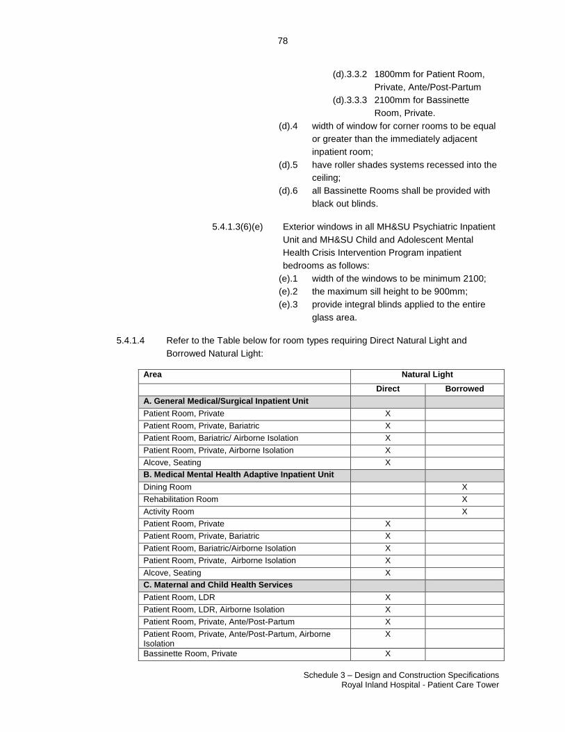
78
Schedule 3 – Design and Construction Specifications Royal Inland Hospital - Patient Care Tower
23507060.2
(d).3.3.2 1800mm for Patient Room,
Private, Ante/Post-Partum
(d).3.3.3 2100mm for Bassinette
Room, Private.
(d).4 width of window for corner rooms to be equal
or greater than the immediately adjacent
inpatient room;
(d).5 have roller shades systems recessed into the
ceiling;
(d).6 all Bassinette Rooms shall be provided with
black out blinds.
5.4.1.3(6)(e) Exterior windows in all MH&SU Psychiatric Inpatient
Unit and MH&SU Child and Adolescent Mental
Health Crisis Intervention Program inpatient
bedrooms as follows:
(e).1 width of the windows to be minimum 2100;
(e).2 the maximum sill height to be 900mm;
(e).3 provide integral blinds applied to the entire
glass area.
5.4.1.4 Refer to the Table below for room types requiring Direct Natural Light and
Borrowed Natural Light:
Area Natural Light
Direct Borrowed
A. General Medical/Surgical Inpatient Unit
Patient Room, Private X
Patient Room, Private, Bariatric X
Patient Room, Bariatric/ Airborne Isolation X
Patient Room, Private, Airborne Isolation X
Alcove, Seating X
B. Medical Mental Health Adaptive Inpatient Unit
Dining Room X
Rehabilitation Room X
Activity Room X
Patient Room, Private X
Patient Room, Private, Bariatric X
Patient Room, Bariatric/Airborne Isolation X
Patient Room, Private, Airborne Isolation X
Alcove, Seating X
C. Maternal and Child Health Services
Patient Room, LDR X
Patient Room, LDR, Airborne Isolation X
Patient Room, Private, Ante/Post-Partum X
Patient Room, Private, Ante/Post-Partum, Airborne Isolation
X
Bassinette Room, Private X
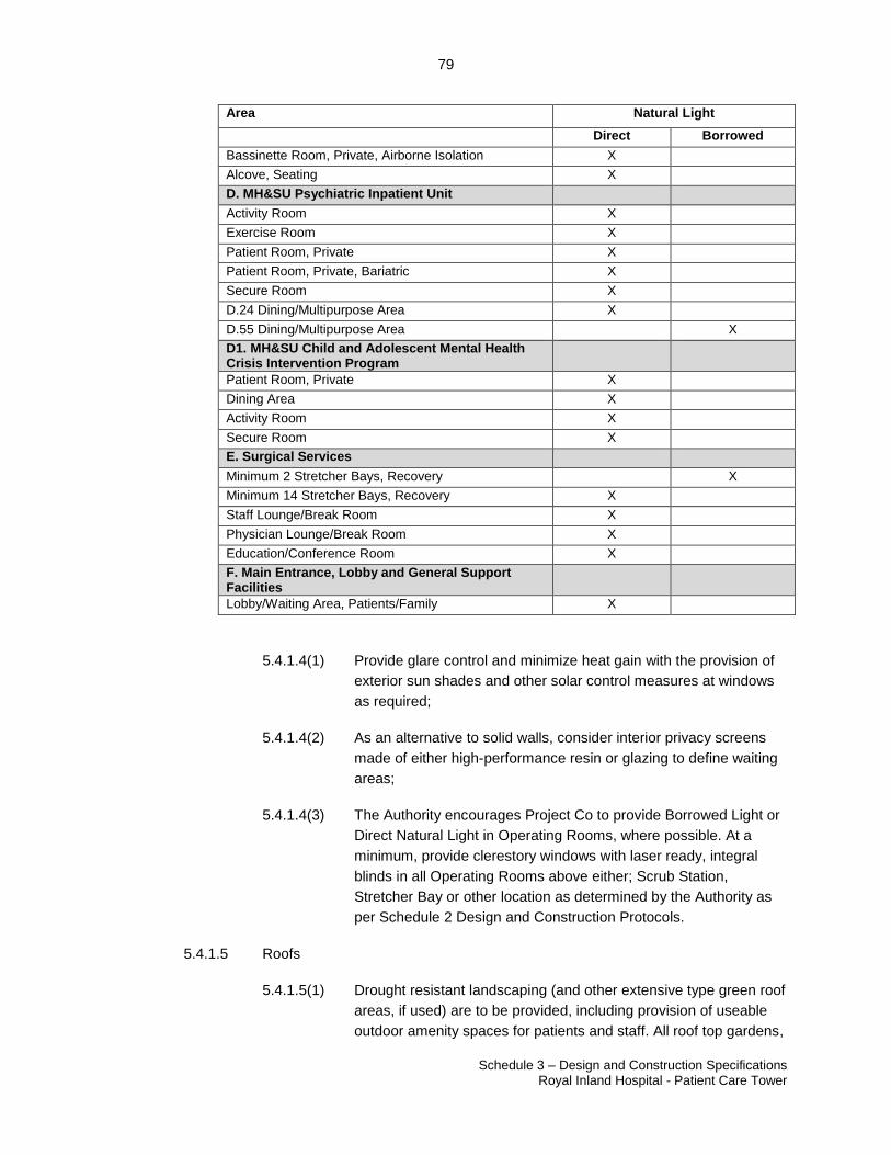
79
Schedule 3 – Design and Construction Specifications Royal Inland Hospital - Patient Care Tower
23507060.2
Area Natural Light
Direct Borrowed
Bassinette Room, Private, Airborne Isolation X
Alcove, Seating X
D. MH&SU Psychiatric Inpatient Unit
Activity Room X
Exercise Room X
Patient Room, Private X
Patient Room, Private, Bariatric X
Secure Room X
D.24 Dining/Multipurpose Area X
D.55 Dining/Multipurpose Area X
D1. MH&SU Child and Adolescent Mental Health Crisis Intervention Program
Patient Room, Private X
Dining Area X
Activity Room X
Secure Room X
E. Surgical Services
Minimum 2 Stretcher Bays, Recovery X
Minimum 14 Stretcher Bays, Recovery X
Staff Lounge/Break Room X
Physician Lounge/Break Room X
Education/Conference Room X
F. Main Entrance, Lobby and General Support Facilities
Lobby/Waiting Area, Patients/Family X
5.4.1.4(1) Provide glare control and minimize heat gain with the provision of
exterior sun shades and other solar control measures at windows
as required;
5.4.1.4(2) As an alternative to solid walls, consider interior privacy screens
made of either high-performance resin or glazing to define waiting
areas;
5.4.1.4(3) The Authority encourages Project Co to provide Borrowed Light or
Direct Natural Light in Operating Rooms, where possible. At a
minimum, provide clerestory windows with laser ready, integral
blinds in all Operating Rooms above either; Scrub Station,
Stretcher Bay or other location as determined by the Authority as
per Schedule 2 Design and Construction Protocols.
5.4.1.5 Roofs
5.4.1.5(1) Drought resistant landscaping (and other extensive type green roof
areas, if used) are to be provided, including provision of useable
outdoor amenity spaces for patients and staff. All roof top gardens,
80
Schedule 3 – Design and Construction Specifications Royal Inland Hospital - Patient Care Tower
23507060.2
Secure Outdoor Patios and outdoor amenity areas are to be
designed so that direct views into neighbouring yards and windows
are not permitted.
5.4.1.5(2) Where not landscaped, roof areas will be designed to be attractive
when viewed from above and should avoid use of large areas of
undifferentiated gravel.
5.4.1.5(3) All roofs are to have Direct Access for maintenance staff. Ensure
design incorporates all safety requirements required by the BC
Building Code and Work Safe BC. Rappelling down from upper
roofs to access lower roofs is not acceptable.
5.4.2 Building Configuration and Internal Circulation
5.4.2.1 Building Entrances
5.4.2.1(1) All access and egress points from the New Facility exterior,
including patient, visitor and drop-off areas, will be protected from
snow and rain by canopies or building overhangs.
5.4.2.1(2) Provide visible places to sit, protected from the prevailing winds
near both the interior and exterior of entrances.
5.4.2.1(3) Entrance designs will create positive and calming first impressions
for patients and families.
5.4.2.1(4) Entrance vestibules will provide complete transparency from the
exterior, from the interior immediately in front of the vestibule, and
from habited spaces adjacent to at least one long side of the
vestibule.
5.4.2.1(5) Entrance vestibules will be configured in L or T shapes and sized
such that only one set of doors will open at one time in order to
preserve the airlock effect for climate control and protected from
the prevailing winds. Ensure adequate distance between the sets
of doors to allow stretchers and wheelchairs and attendants to fit
lengthwise into the vestibule. No rotating doors are permitted.
5.4.2.1(5)(a) Entrance vestibules will be provided with foot grilles
which are recessed and flush with the floor surface
and equipped with floor drains to reduce the quantity
of soil and water being brought into the New Facility
by pedestrians.
5.4.2.1(6) Provide automatic doors at all public entrances and exits to the
Building and to departments. Doors will be configured for push-pull
manual operation in addition to automatic operation.
81
Schedule 3 – Design and Construction Specifications Royal Inland Hospital - Patient Care Tower
23507060.2
5.4.2.1(7) Pedestrian interest and comfort at entries will be provided through
specifically designed seating, signage, lighting and features that
signal the Building's use.
5.4.2.1(7)(a) Provide entrances to the New Facility, at a minimum
at the following locations;
(a).1 From RIH Campus ring road and pick-up
drop off area to the Main Entrance;
(a).2 from the underground parking to the Main
Entrance.
5.4.2.1(7)(b) A high volume of patients/visitors to the New Facility
will arrive at Level 2 from the Clinical Services
Building. Minimize the distance between the Clinical
Services Building bridge and the New Facility public
elevators.
5.4.2.2 Main Entrance
5.4.2.2(1) The New Facility Main Entrance will be the new public entry point
to the Hospital, with the existing entrance and traffic circle at Level
2 converted to Emergency Department use.
5.4.2.2(2) The New Facility main entrance shall have a vehicle drop-off with
lay-by stalls spots provided; refer to On-Site Works. Longer term
underground parking shall be easily accessible from the drop-off
zone.
5.4.2.2(3) The New Facility Main Entrance shall be the after-hours entrance
for the Hospital and as such will be monitored by Security Staff
from the Protection Services/Volunteers Kiosk.
5.4.2.3 Exit Stairs
5.4.2.3(1) Locate exit stairs strategically for the convenience of staff to
promote the use of stairs over elevators.
5.4.2.3(2) Locate exit stairs with Convenient Access from circulation routes
and as per section 5.1.1.4.
5.4.2.3(3) Avoid stair locations that negatively impact planning flexibility or
constrain desirable views from Clinical Spaces and staff work
areas.
5.4.2.3(4) Provide windows for daylight and views from exterior walls of
stairwells for orientation, amenity and safety by deterring
undesirable and criminal activity or behaviour. Provide adequate
82
Schedule 3 – Design and Construction Specifications Royal Inland Hospital - Patient Care Tower
23507060.2
lighting into stairwells for security at night but do not permit direct
views into neighbours’ back windows and yards.
5.4.2.3(5) Provide stairwell design that facilitates the use of evacuation sleds
excluding exit stairwells from the underground parking.
5.4.2.4 Convenience Stairs
5.4.2.4(1) Consider the provision of convenience stairs, located strategically
to reduce elevator use by staff, visitors and patients. Use open
stairs where possible unless otherwise required by this Schedule.
5.4.2.4(2) Convenience stairs will have finishes similar to the floor levels they
serve and in all cases will have a finished floor and steel handrails
and guardrails.
5.4.2.4(3) Provide a convenience stair in the following locations:
5.4.2.4(3)(a) Provide an open convenience stair between the
Lobby/Waiting Area, Patients/Family and Level 2 of
New Facility located adjacent to the public elevators
for use by staff, visitors and patients;
5.4.2.4(3)(b) Between Control and Patient Holding Area
(Unrestricted Zone) and Staff Amenity and
Administration Area, exit stair is permitted to serve
as the convenience stair provided the floor finishes
in the stair between these two floors matches the
connecting corridor floor finishes that the stair
serves, have stair coverings and the stair walls have
washable finishes, to meet infection control
standards.
5.4.2.5 Safety of Stairs and Areas Open to Below
5.4.2.5(1) Where horizontal gaps at the switchback between flights of stairs
in a stairwell exceeds 400mm, provide steel or glass guardrails
extending full height from the landing or stairs to the underside of
the one above to prevent public, patients or staff from using them
for self-harm.
5.4.2.5(2) Stairwells shall not allow for individuals to hide in the landing areas
and solid walls shall not be used to divide flights of stairs;
5.4.2.5(3) Where floor areas are open to the floor area below, provide full
height floor to ceiling glazing to prevent public, patients or staff
from self-harm.
83
Schedule 3 – Design and Construction Specifications Royal Inland Hospital - Patient Care Tower
23507060.2
5.4.2.5(4) Provide guards in stairwells as required by BC Building Code at
window openings.
5.4.2.6 Corridors
5.4.2.6(1) Corridor widths will be as follows:
5.4.2.6(1)(a) Corridors shall be a minimum dimension of 2400 mm
clear for stretcher/bed/pallet movement within the
Building unless noted otherwise;
5.4.2.6(1)(b) Corridors within the MH&SU Child and Adolescent
Mental Health Crisis Intervention Program, with the
exception of Pediatric Psychiatry Inpatient Unit
(PPIU) which are required to be 2400mm, shall be
minimum 1800mm wide;
5.4.2.6(1)(c) Corridors at elevators serving patient and support
services will have a minimum clear area of 3100mm
deep by 3400mm long in front of each elevator to
accommodate movement of beds, stretchers, staff,
carts and supply truck trains; and
5.4.2.6(1)(d) Corridors servicing only offices, or similar areas
where beds, stretchers, carts and supply truck trains
are not required, shall be minimum 1500 mm wide.
5.4.2.6(2) Design corridor ceiling space to accommodate all mechanical and
electrical services.
5.4.2.6(3) Design corridors to be level wherever possible. Transitions
between the existing Hospital and the New Facility will provide an
even transition between Level 0 and Level 4 and minimize the use
of ramps. Where ramps are required, minimize the slope to the
greatest extent possible to a maximum of 2%.
5.4.2.6(4) Design corridors to have soft corners to allow ease of movement
for stretchers, beds and accompanying medical staff and
equipment.
5.4.2.6(5) To minimize risk of collisions at intersecting corridors, provide
vandal resistant convex mirrors made from polycarbonate with a
minimum tensile strength of 9,400 psi at all intersections where
stretchers, beds, equipment or carts are traveling. Completely fill
the cavity behind the mirrors with high-density water blown
urethane foam. Mirror perimeter shall be secured with fully
enclosed heavy duty powder coated steel frame mounted flush
with the wall and ceiling and with countersunk screw holes with
84
Schedule 3 – Design and Construction Specifications Royal Inland Hospital - Patient Care Tower
23507060.2
tamper-resistant fasteners. Mirror locations and quantity to be
determined by the Authority through the Schedule 2 Appendix 2C
Review Procedure, and Authority review of post-occupancy
operations.
5.4.2.6(6) Corridors in Clinical Spaces will have alcoves for storage of
equipment. The alcoves will be dispersed in the Clinical Spaces
allowing corridors to be kept clear of equipment and supplies.
Corridors will have rest areas for patients to promote mobility and
activity. Alcoves shall not reduce required corridor widths.
5.4.2.6(7) Corridors outside each of the Operating Room will have disbursed
and conveniently located storage areas, including stretcher storage
and an area for scrub sinks items directly adjacent the entry door.
Refer to Appendix 3A Clinical Specifications and Functional Space
Requirements.
5.4.2.6(8) For the Medical Mental Health Adaptive Inpatient Unit, MH&SU
Psychiatric Inpatient Unit and MH&SU Child and Adolescent
Mental Health Crisis Intervention Program ensure corridors to, and
within the Component minimize opportunities for hiding places.
5.4.3 Acoustics and Noise Control
5.4.3.1 Design and construct the New Facility in consultation with a Consultant in
Acoustics and Noise Control.
5.4.3.2 Design and construct the New Facility to comply, at a minimum, with the
requirements described in Appendix 3D Acoustic and Noise Control Measures.
5.4.3.3 Provide acoustic and noise measures necessary to create a healing environment
for patients, a safe and comfortable environment for staff and confidentiality
where it is required.
5.4.3.4 Acoustic and noise control measures shall be provided to meet the functional
requirements of the space by:
5.4.3.4(1) attenuation of sound within public, patient and staff environments;
5.4.3.4(2) sound isolation between the exterior and interior spaces;
5.4.3.4(3) sound isolation between interior spaces within the Building at both
horizontal and vertical separations;
5.4.3.4(4) sound and vibration isolation of building service noises and sound
isolation of Building service rooms;
5.4.3.4(5) sound isolation as required for specialty rooms such as video-
conferencing;
85
Schedule 3 – Design and Construction Specifications Royal Inland Hospital - Patient Care Tower
23507060.2
5.4.3.4(6) sound attenuation of noise from equipment within rooms; and
5.4.3.4(7) sound masking system referred to in Appendix 3D Acoustic and
Noise Control Measures.
5.4.3.5 Optimum sound isolation requires that the integrity of gypsum board partitions
and ceilings (mass) never be violated by vent or grille cut-outs or by recessed
cabinets, light fixtures, etc.
5.4.3.6 Where penetrations are necessary, minimize placing them back-to-back and next
to each other. Stagger electrical boxes and medical gas outlets, preferably by at
least one stud space. Use mineral fiber insulation to seal joints around all cut-
outs such as electrical, TV and telephone outlets, plumbing escutcheons,
recessed cabinets, and bathtubs.
5.4.3.7 Minimize constructions such as ducts, rigid conduits, or corridors that act as
tubes to transmit sound from one area to another. At common supply and return
ducts, provide sound attenuation liners at the diffuser and/or grill to maintain the
acoustical requirements described in Appendix 3D Acoustic and Noise Control
Measures. Seal around conduits.
5.4.3.8 Isolate structure-borne vibrations and sound with resilient mountings on vibrating
equipment to minimize sound transfer to structural materials. Provide ducts,
pipes, and conduits with resilient, non-rigid boots or flexible couplings where they
leave vibrating equipment; isolate from the structure with resilient gaskets and
sealant where they pass through walls, floors, or other Building surfaces.
5.4.3.9 Use acoustic screens, vibration isolators, and carefully selected exterior
equipment to prevent exterior noise that neighbours may find offensive.
5.4.3.10 Include effective noise attenuation design of the New Facility to meet the heliport
noise requirements provided in Appendix 3D Acoustic and Noise Control
Measures expected from helicopter approach and departure from adjacent
rooftop Heliport as per reference in Heliport report by Ground Effect Aerodrome
Consulting Ltd. dated September 16, 2016.
5.4.3.11 Refer to Appendix 3C Room Data Sheets for minimum wall STC/NIC ratings.
Project Co shall meet all STC and NIC requirements of Table 1 – STC/NIC
Ratings of Demising Walls and Floor/Ceiling Assemblies based on the adjacency
combination. Where there is a conflict between Appendix 3C Room Data Sheets
and Appendix 3D Acoustic and Noise Control Measures, the more stringent
requirement shall govern. Any post construction testing used to assess in-situ
performance in terms of the ASTC rating must be within 5 points of the more
stringent STC rating. Where the room dimensions are not in compliance with the
ASTM standard for ASTC testing, NIC tests can be performed and must meet the
more stringent NIC rating.
5.4.3.12 Acoustic Performance Testing
86
Schedule 3 – Design and Construction Specifications Royal Inland Hospital - Patient Care Tower
23507060.2
5.4.3.12(1) Post-construction performance verification tests shall be carried
out at the earliest opportunity on two separate examples of each
unique wall assembly having a required NIC rating (Refer Table 1
in Appendix 3D: Acoustic and Noise Control Measures) of 42 or
more. Testing to be done per appropriate ASTM standards to
obtain ASTC values. Where room dimensions are not in
compliance with the ASTM standard for ASTC testing, NIC tests
may be performed. If both wall assemblies do not achieve an
ASTC rating within 5 points of the STC rating or the required NIC
rating (as appropriate), then another two walls shall be tested to
establish the extent of the problem. Corrective measures shall be
taken as required and all failing walls retested.
5.4.3.12(2) Post-construction performance verifications tests shall be carried
out of HVAC noise levels (NC) in 50% of all occupied spaces as
listed in Table 2 of Appendix 3D: Acoustic and Noise Control
Measures. The testing shall be focused (but not exclusively) on
those spaces located closest to the mechanical spaces serving the
various portions of the Facility. Where the NC requirements of
Table 2, Appendix 3D are not met, measures shall be taken to
reduce the HVAC noise levels to the levels shown in Table 2 and
the rooms retested.
5.4.3.12(3) Post-construction performance verification tests shall be taken of
the reverberation times within two unique examples of each type of
space listed in Table 3 of Appendix 3D: Acoustic and Noise Control
Measures. Where the measured reverberation times do not meet
the requirements of Table 3, Appendix 3D: Acoustic and Noise
Control Measures, corrective measures shall be taken to achieve
the levels shown in Table 3 and the space retested. Similar
corrective measures shall then be applied to all other spaces of the
same type.
5.4.4 Building Envelope
5.4.4.1 Design and construct a building envelope as follows:
5.4.4.1(1) To prevent the accumulation and stagnation of rain, snow, ice and
dirt on the horizontal and vertical surfaces of the building
envelope(s) required for the climate the New Facility is situated in;
5.4.4.1(2) To ensure that water, snow and ice sheds safely from exterior
surfaces and is not trapped in the assembly where it may cause
deterioration or staining, or present a danger to the safety of any
person;
87
Schedule 3 – Design and Construction Specifications Royal Inland Hospital - Patient Care Tower
23507060.2
5.4.4.1(3) Meet all the requirements of BC Building Code, City of Kamloops
bylaws and ASHRAE 90.1;
5.4.4.1(4) Except for exposed Architectural Concrete walls, in accordance
with pressure equalized rain-screen wall design principles with an
exterior insulated wall assembly and demonstrate that the
proposed details fulfill the rainscreen principles; and
5.4.4.1(5) With a predicted service life that exceeds 50 years as defined in
CSA S478-95:
5.4.4.1(5)(a) For components and assemblies whose categories
of failure are 6, 7, or 8 in Table 3 in CSA S478-95,
use a design service life equal to the design service
for the New Facility;
5.4.4.1(5)(b) For components and assemblies whose categories
of failure are 4 or 5 in Table 3 in CSA S478-95, use
a design service life equal to at least half of the
design service life of the New Facility; and
5.4.4.1(5)(c) Where component and assembly design service
lives are shorter than the design service life of the
New Facility, design and construct so they can be
readily replaced.
5.4.4.2 Design of the New Facility, including the structure and structural components,
shall minimize effects of corrosion and deterioration due to environmental
impacts and use, including Malicious Damage by use of measures such as:
5.4.4.2(1) Concrete crack control joints and expansion/contraction joints;
5.4.4.2(2) High strength concrete mixes, proportioned to durability
requirements for exposure and use;
5.4.4.2(3) Reinforcing of concrete for crack control;
5.4.4.2(4) Hot-dip galvanize or paint with a two part epoxy paint system all
exposed steel; and
5.4.4.2(5) Embedded steel protection angles and skid plates for service
areas.
5.4.4.3 Ensure continuation of the air barrier, vapour barrier, thermal barrier and
moisture barrier across the entire envelope including foundations, walls and
roofs;
5.4.4.4 Accommodate the high humidity service conditions inside the New Facility;
88
Schedule 3 – Design and Construction Specifications Royal Inland Hospital - Patient Care Tower
23507060.2
5.4.4.5 Below grade assembly will resist the ingress of water. Where the exterior wall of
an occupied floor is below grade, the wall is to be provided with waterproofing.
Below grade underground parking level walls do not require to be waterproofed;
5.4.4.6 Condensation within building envelope assemblies or on interior surfaces shall
not be permitted under any operational condition;
5.4.4.7 Accommodate differential movement due to temperature variations, and
structural movement;
5.4.4.8 Avoid thermal bridging;
5.4.4.9 Back-up walls for outer cladding will consist of concrete masonry units, poured in
place reinforced concrete or structural metal framing backup system. Design for
deflection of interior finishes shall conform to code in all conditions;
5.4.4.10 Construction materials that are not adequately secured or are breakable can
become weapons. The design and construction of the New Facility shall use only
durable materials, secured such that they cannot be dislodged by patients;
5.4.4.11 The applicable areas of the New Facility designed for patient use shall be
designed and constructed so as to prevent the opportunity for hiding of
contraband. Interfaces between walls, windows, structure, finishes and a like in
all areas will form straight lines with minimal joints. Provide pick-proof joint
sealant at all exposed joints in patient occupied areas which otherwise provide
the patient an opportunity to damage the finish;
5.4.4.12 Project Co to retain a Building Envelope Consultant through design and
construction process and provide for review during construction. Provide a
Building Envelope Report, signed by the Building Envelope Consultant, at the
completion of the project confirming the as-built construction conforms to the
recommendations in the Building Envelope Report;
5.4.4.13 Submit building envelope test results, witnessed by the Building Envelope
Consultant, to the Authority verifying that the building envelope is meeting all
requirements;
5.4.4.14 The completed building shall be tested and the air leakage rate of the building
envelope is intended not to exceed 0.40 cfm/ft2 at a pressure differential of 0.3
inches water gauge (2.0 L/s.m2 at 75 Pa) at the upper 96 percent confidence
interval in accordance with ASTM E 779 or an equivalent method approved by
the code official. A report that includes the tested surface area, floor area, air by
volume, stories above grade, and leakage rates shall be submitted to the building
Authority and code official. The following modifications shall be made to ASTM E
779:
5.4.4.14(1) Tests shall be accomplished using either (1) both pressurization
and depressurization or (2) pressurization alone, but not
89
Schedule 3 – Design and Construction Specifications Royal Inland Hospital - Patient Care Tower
23507060.2
depressurization alone. If both pressurization and depressurization
are not tested, the air leakage shall be plotted against the
corrected P for pressurization in accordance with section 9.4 of
ASTME E 779;
5.4.4.14(2) The test pressure range shall be from 25 Pa to 80 Pa per Section
8.10 of ASTM E 779, but the upper limit shall not be less than 50
Pa and the difference between the upper and lower limit shall not
be less than 25Pa;
5.4.4.14(3) If the pressure exponent n is less than 0.45 or greater than 0.85
per Section 9.6.4 of ASTM E779, the test shall be rerun with
additional readings over a longer time interval.
5.4.4.15 If the tested rate exceeds that assumed as part of the energy modeling and
associated Design and Construction Energy Target, a visual inspection of the air
barrier shall be conducted and any leaks noted shall be sealed to the extent
practicable. An additional report identifying the corrective actions taken to seal air
leaks shall be submitted to the building Authority and the code official and any
further requirement to meet the leakage air rate will be waived (aside from the
impact on the Design and Construction Energy Target).
5.4.4.16 In accordance with pressure equalized rain-screen wall design principles with an
exterior insulated wall assembly and demonstrate that the proposed details fulfill
the rain screen principles;
5.4.4.17 The wall assembly will be insulated primarily exterior to the interior wall or back-
up wall; Design and construct all exterior wall cladding systems for the New
Facility in accordance with ‘Rain-Screen Principles’;
5.4.4.18 Design exterior walls in accordance with the ‘rain-screen principles’ as described
by the “National Research Council Canada, Designing Exterior Walls According
to the Rainscreen Principle, Construction Technology Update No. 34, Dec. 1999;
5.4.4.19 For the purpose of this Schedule, ‘Rain-Screen Principles’ shall mean that the
applicable wall cladding system incorporates: a means to drain all accumulated
water to the exterior of the New Facility; materials installed to shed precipitation;
means of preventing moisture penetration through the exterior of the wall
assembly; flashings, drips or overhangs, sufficient to deflect accumulated water
away from the New Facility face, at all:
5.4.4.19(1) Changes in plane;
5.4.4.19(2) Intersections of walls and roofs;
5.4.4.19(3) Changes in cladding material; and
5.4.4.19(4) Window and door heads or sills.
90
Schedule 3 – Design and Construction Specifications Royal Inland Hospital - Patient Care Tower
23507060.2
5.4.4.20 Include a continuous air space of minimum 25 mm clear width.
5.4.5 Interior Walls and Partitions
5.4.5.1 Use interior walls and partition systems that:
5.4.5.1(1) Provide acoustic separations as required for the specific functions
to be carried out in the spaces affected, and in accordance with the
requirements of Appendix 3D Acoustic and Noise Control
Measures and with project test requirements which include
demonstration of conformance with Appendix 3D Acoustic and
Noise Control Measures via ASTC or NIC testing as is appropriate
for the space; and
5.4.5.1(2) Provide separations required for fire safety and protection.
5.4.5.2 Seismic resistance capabilities will conform to the requirements of CSA S832-06
Guidelines for Seismic Risk Reduction of Operational and Functional
Components of Buildings.
5.4.5.3 Design and select interior walls and partitions, partition systems and interior
finishes to comply with the following criteria as may be relevant for the particular
or specific functions enclosed:
5.4.5.3(1) cleaning, maintenance and infection prevention and control as
relevant for the particular or specific function;
5.4.5.3(2) wall finishes shall be washable using hospital grade disinfectant.
In the vicinity of plumbing fixtures, wall finishes shall be smooth
and water resistant;
5.4.5.3(2)(a) Washable painted surfaces will consist of a water-
borne epoxy paint.
5.4.5.3(3) in OR’s, Airborne Isolation Rooms and the MDR Cart Marshalling
Area, Sterile, MDR Receiving/ Breakout Room and MDR Cart
Marshalling Area, Soiled, wall finishes shall be free of fissures,
open joints, or crevices that can retain or permit passage of dirt
particles;
5.4.5.3(4) in the MDR Cart Marshalling (Sterile and Soiled) areas ceiling,
walls, and work surfaces in this area will be impervious to
moisture.
5.4.5.3(5) resist damage due to normal wear and resist damage due to
collision in high traffic areas; permanence and durability including
impact resistance
5.4.5.3(6) non-toxic/ non-allergenic;
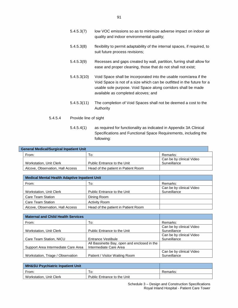
91
Schedule 3 – Design and Construction Specifications Royal Inland Hospital - Patient Care Tower
23507060.2
5.4.5.3(7) low VOC emissions so as to minimize adverse impact on indoor air
quality and indoor environmental quality;
5.4.5.3(8) flexibility to permit adaptability of the internal spaces, if required, to
suit future process revisions;
5.4.5.3(9) Recesses and gaps created by wall, partition, furring shall allow for
ease and proper cleaning, those that do not shall not exist;
5.4.5.3(10) Void Space shall be incorporated into the usable room/area if the
Void Space is not of a size which can be outfitted in the future for a
usable sole purpose. Void Space along corridors shall be made
available as completed alcoves; and
5.4.5.3(11) The completion of Void Spaces shall not be deemed a cost to the
Authority
5.4.5.4 Provide line of sight
5.4.5.4(1) as required for functionality as indicated in Appendix 3A Clinical
Specifications and Functional Space Requirements, including the
following:
General Medical/Surgical Inpatient Unit
From: To: Remarks:
Workstation, Unit Clerk Public Entrance to the Unit Can be by clinical Video Surveillance
Alcove, Observation, Hall Access Head of the patient in Patient Room
Medical Mental Health Adaptive Inpatient Unit
From: To: Remarks:
Workstation, Unit Clerk Public Entrance to the Unit Can be by clinical Video Surveillance
Care Team Station Dining Room
Care Team Station Activity Room
Alcove, Observation, Hall Access Head of the patient in Patient Room
Maternal and Child Health Services
From: To: Remarks:
Workstation, Unit Clerk Public Entrance to the Unit Can be by clinical Video Surveillance
Care Team Station, NICU Entrance Vestibule Can be by clinical Video Surveillance
Support Area Intermediate Care Area All Bassinette Bay, open and enclosed in the Intermediate Care Area
Workstation, Triage / Observation Patient / Visitor Waiting Room Can be by clinical Video Surveillance
MH&SU Psychiatric Inpatient Unit
From: To: Remarks:
Workstation, Unit Clerk Public Entrance to the Unit
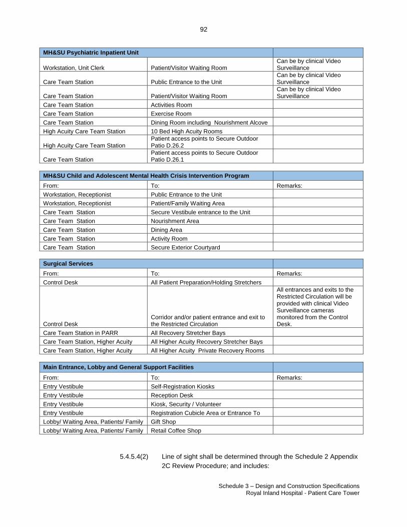
92
Schedule 3 – Design and Construction Specifications Royal Inland Hospital - Patient Care Tower
23507060.2
MH&SU Psychiatric Inpatient Unit
Workstation, Unit Clerk Patient/Visitor Waiting Room Can be by clinical Video Surveillance
Care Team Station Public Entrance to the Unit Can be by clinical Video Surveillance
Care Team Station Patient/Visitor Waiting Room Can be by clinical Video Surveillance
Care Team Station Activities Room
Care Team Station Exercise Room
Care Team Station Dining Room including Nourishment Alcove
High Acuity Care Team Station 10 Bed High Acuity Rooms
High Acuity Care Team Station Patient access points to Secure Outdoor Patio D.26.2
Care Team Station Patient access points to Secure Outdoor Patio D.26.1
MH&SU Child and Adolescent Mental Health Crisis Intervention Program
From: To: Remarks:
Workstation, Receptionist Public Entrance to the Unit
Workstation, Receptionist Patient/Family Waiting Area
Care Team Station Secure Vestibule entrance to the Unit
Care Team Station Nourishment Area
Care Team Station Dining Area
Care Team Station Activity Room
Care Team Station Secure Exterior Courtyard
Surgical Services
From: To: Remarks:
Control Desk All Patient Preparation/Holding Stretchers
Control Desk Corridor and/or patient entrance and exit to the Restricted Circulation
All entrances and exits to the Restricted Circulation will be provided with clinical Video Surveillance cameras monitored from the Control Desk.
Care Team Station in PARR All Recovery Stretcher Bays
Care Team Station, Higher Acuity All Higher Acuity Recovery Stretcher Bays
Care Team Station, Higher Acuity All Higher Acuity Private Recovery Rooms
Main Entrance, Lobby and General Support Facilities
From: To: Remarks:
Entry Vestibule Self-Registration Kiosks
Entry Vestibule Reception Desk
Entry Vestibule Kiosk, Security / Volunteer
Entry Vestibule Registration Cubicle Area or Entrance To
Lobby/ Waiting Area, Patients/ Family Gift Shop
Lobby/ Waiting Area, Patients/ Family Retail Coffee Shop
5.4.5.4(2) Line of sight shall be determined through the Schedule 2 Appendix
2C Review Procedure; and includes:
93
Schedule 3 – Design and Construction Specifications Royal Inland Hospital - Patient Care Tower
23507060.2
5.4.5.4(2)(a) From: Location where staff normally perform their
work, centreline of inner entrance doors at the Entry
Vestibule, or centre of the Lobby/Waiting Area;
5.4.5.4(2)(b) To all four corners of the space or Secure Outdoor
Patio where possible, centre point of entrance doors,
head of the patient bed for Clinical Spaces, and
centre point of the bedroom door for the 10 Bed
High Acuity Room.
5.4.5.4(3) Line of sight provides the ability to see what is important from
where a person is located; the implications to the design include
the general layout, use of low walls and furniture, low equipment,
glazed walls, straight corridors and doorways that line up.
5.4.5.4(4) Location and design of interior walls and columns shall minimize
disruption of line of sight.
5.4.5.4(5) If the unit entry is not clearly visible, provide video surveillance
camera(s), video intercom or Aphone. Provide view of the unit
entry points from both sides of the door with monitors and provide
a remote unit entry door(s) release.
5.4.5.4(6) Provide full height glazing with lower horizontal mullion at handrail
height for a minimum of 1.5m where line of site is required and a
partition is required.
5.4.5.4(7) Provide low height furniture, Millwork and equipment where
possible to achieve line of sight where required.
5.4.5.5 Location and design of interior walls and columns shall minimize disruption of
exterior views and line of sight.
5.4.5.6 Provide fittings, attachments and internal bracing/backing as required to
accommodate and support wall-mounted clinical and non-clinical fixtures, storage
systems and equipment, including equipment at videoconferencing and other
applicable rooms.
5.4.5.7 At a minimum, Project Co shall provide wall backing:
5.4.5.7(1) Full width of the wall to a minimum height of 1800 mm in alcoves
around hand hygiene sinks.
5.4.5.7(2) The wall which has the head of the patient’s bed or stretcher
towards it shall have backing the full width and height of the wall.
94
Schedule 3 – Design and Construction Specifications Royal Inland Hospital - Patient Care Tower
23507060.2
5.4.5.7(3) Full width and height of the walls in all Medication Rooms except
where equipment is located such as Automated Medication
Management System or refrigerator.
5.4.5.7(4) Full width and height of the walls in all Clean Utility, Soiled Utility,
Equipment Storage, Housekeeping Rooms and Scrub Sink bays.
5.4.5.7(5) Full width and height of walls in Rehabilitation Room to support
wall mounted dumbbells, weights and other accessories.
5.4.5.7(6) As required to support Millwork, washroom accessories, and any
wall mounted items on the Authority’s equipment list.
5.4.5.7(7) Where lead aprons are stored both inside and outside of Operating
Rooms.
5.4.5.8 Partition design to allow for built in pass through where required.
5.4.5.9 Provide protection against water damage in spaces that contain equipment or
services by providing required partition base design, such as concrete curbs.
5.4.5.10 Steel studs to receive Abuse Resistant or Impact Resistant Gypsum panels shall
be proprietary stud materials that also achieve the limiting heights table for
interior non-loadbearing steel framing and meet / exceed the STC sound
requirement within Appendix 3D. Material design thickness not less than 0.0188
in. (0.478 mm) in accordance with ASTM C645-14 Standard Specification for
Non-structural Steel Framing Members. Walls shall comply with Appendix 3D
Acoustic and Noise Control Measures.
5.4.6 Surfaces
5.4.6.1 Surfaces shall have the following characteristics, consistent with their functional
purpose:
5.4.6.1(1) resistant to microbial spread and growth;
5.4.6.1(2) non porous or smooth;
5.4.6.1(3) durable;
5.4.6.1(4) seamless;
5.4.6.1(5) resilient and impact resistant;
5.4.6.1(6) non-toxic/ non allergenic;
5.4.6.1(7) presenting minimal glare;
5.4.6.1(8) constructed in a way that shall not soak up or harbour moisture;
95
Schedule 3 – Design and Construction Specifications Royal Inland Hospital - Patient Care Tower
23507060.2
5.4.6.1(9) water impermeable in areas where water or dampness can occur;
5.4.6.1(10) with front edges of the tops of stainless steel counters with marine
edges and rounded corners with minimum 25mm radius.
5.4.7 Ceilings
5.4.7.1 Design ceilings to accommodate ceiling-mounted equipment as per the Schedule
2, Appendix 2E Equipment List and as required per Appendix 3A Clinical
Specifications and Functional Space Requirements.
5.4.7.2 For all ceiling mounted or recessed devices in Medical Mental Health Adaptive
Inpatient Unit, MH&SU Psychiatric Inpatient Unit and MH&SU Child and
Adolescent Mental Health Crisis Intervention Programs such as light fixtures,
diffusers, smoke detectors or similar provide concealed tamper resistant
fasteners which prevent entry into the ceiling space or adjoining spaces by
clients.
5.4.7.3 Accessible ceiling systems may provide access to the ceiling spaces throughout
the system or at specific and particular locations.
5.4.7.4 Ceiling systems other than in ORs will comprise a major component of the
acoustic or sound attenuation function as required in the spaces in which they
are installed and will comply with the requirements of Appendix 3D Acoustic and
Noise Control Measures.
5.4.7.5 Ceiling penetrations shall be properly sealed to prevent the entrance of air,
insects and rodents.
5.4.7.6 Ceiling height shall not be less than 2.75 meters above the finished floor in all
areas except for the following:
5.4.7.6(1) ceiling heights in corridors which have ramps, storage rooms and
toilet rooms will be not less than 2.4 metres (except that ceiling
heights in small, normally unoccupied spaces such as storage
alcoves may be reduced to a minimum of 2.1 meters);
5.4.7.6(2) Suspended tracks, rails and pipes located in the traffic path for
patients in beds and/or on stretchers, including those in patient
service areas, shall not be less than 2.6 meters above the finished
floor, including door frame clearances;
5.4.7.6(3) Ceiling heights in OR’s to be of a height to accommodate booms
and be a minimum:
5.4.7.6(3)(a) Operating Room, Standard 3.5 meters
5.4.7.6(3)(b) Operating Room, Interventional Urology 3.5 meters
96
Schedule 3 – Design and Construction Specifications Royal Inland Hospital - Patient Care Tower
23507060.2
5.4.7.6(3)(c) Operating Room, Hybrid 3.5 meters
5.4.7.6(4) Ceiling height in Level 4 North PARR and Level 4 West Daycare
Surgery renovation area shall be a minimum of 2.4 m;
5.4.7.6(5) To allow connections described in 4.4 Connections to Existing
Hospital and Site Services, the Authority shall consider reduced
ceiling heights of no less than 2.4 metres in these Components; C.
Maternal and Child Health Services, D1. MH&SU Child and
Adolescent Mental Health Crisis Intervention and F. Main
Entrance, Lobby and General Support Facilities Main
Entrance/Lobby Area except for public or staff/services elevator
lobbies and the following spaces:
5.4.7.6(5)(a) Within Component C. Maternal and Child Health
Services;
(a).1 Exam Room, Triage/Observation
(a).2 Patient Room, LDR
(a).3 Patient Room, LDR, Airborne Isolation
(a).4 Patient Room, Private, Ante-Post-Partum
(a).5 Patient Room, Private, Ante-Post-Partum,
Airborne Isolation
(a).6 Bassinette Room, Private
(a).7 Bassinette Room, Private, Airborne Isolation
(a).8 Bassinette Bay, enclosed
(a).9 Bassinette Bay, open
(a).10 Care Team Station
(a).11 Care Team Workroom
(a).12 Team Conference/Family Education Room
(a).13 Care Team Station, NICU
(a).14 Intermediate Care Area Support Area
5.4.7.6(5)(b) Within Component D1. MH&SU Child and
Adolescent Mental Health Crisis Intervention;
(b).1 Patient Room, Private
(b).2 Secure Room
(b).3 Patient/Family Waiting Area
(b).4 Group Rooms
(b).5 Staff Room
(b).6 Care Team Station
(b).7 Activity Room
5.4.7.6(5)(c) Within Component F. Component Main Entrance,
Lobby and General Support Facilities Main
Entrance/Lobby Area;
(c).1 Entrance Vestibule
(c).2 Lobby/Waiting Area, Patients/Family
97
Schedule 3 – Design and Construction Specifications Royal Inland Hospital - Patient Care Tower
23507060.2
(c).3 Gift Shop
(c).4 Retail Coffee Shop
5.4.7.6(5)(d) Within Component G. Respiratory Therapy Services;
(d).1 Pulmonary Function Testing Lab
(d).2 Exam Room
(d).3 Bronchoscopy Room
(d).4 Stretcher Holding
(d).5 Stretcher Bays, Recovery
(d).6 Waiting Area
5.4.7.6(6) Ceiling height in Patients/Family Lobby/Waiting Area shall be a
minimum of 6.0 m.
5.4.7.7 Not used.
5.4.7.8 Design and select ceiling systems and ceiling finishes to comply with the
following criteria as may be relevant to the particular or specific functions of the
space:
5.4.7.8(1) cleaning, maintenance and infection prevention and control;
5.4.7.8(2) flexibility and access to the spaces above;
5.4.7.8(3) compatibility with mechanical, plumbing, electrical,
communications services and fixtures;
5.4.7.8(4) low VOC emissions so as to minimize adverse impact on indoor air
quality and indoor environmental quality; and
5.4.7.8(5) aesthetic and design qualities to provide a healing environment for
the patients, staff and public.
5.4.7.9 Ceiling finishes in semi restricted rooms will be compliant with CSA Z8000, refer
to section 12.2.5.4 Ceilings. Semi restricted rooms include:
5.4.7.9(1) Airborne Isolation Rooms and Anterooms
5.4.7.9(2) Clean or Restricted Circulation corridors
5.4.7.9(3) Clean rooms such as Storage Clean Equipment and Clean Utility
Room
5.4.7.9(4) Specialized radiographic rooms
5.4.7.10 Ceilings in restricted rooms such as OR’s shall be monolithic and shall be
constructed with drywall.
98
Schedule 3 – Design and Construction Specifications Royal Inland Hospital - Patient Care Tower
23507060.2
5.4.7.11 Ceilings in the MDR Cart Marshalling Area, Sterile, MDR Receiving/Breakout
Room and MDR Cart Marshalling Area, Soiled shall be resistant to humidity in
spaces where steam and moisture are encountered. Shall be constructed of non-
porous, non-shedding materials with recessed, enclosed pipes and fixtures so as
to create a flush surface, facilitating frequent cleaning. Ceiling access shall be
provided for maintenance of pipes and fixtures. Ceilings shall be constructed
without fissures, open joints, or crevices that can retain or permit passage of dirt
particles or steam and condensation.
5.4.7.12 All piping, duct work, and structure will be covered by a finished ceiling in location
where dust fallout would present a potential problem. All overhead piping and
ductwork in the Enclosed Atrium, dining or food handling areas shall be
concealed behind a solid finished ceiling.
5.4.7.13 Ceilings will be designed for seismic restraint according to the BC Building Code.
5.4.7.14 Provide fittings, attachments and internal bracing/backing as required to
accommodate and support ceiling-mounted clinical and non-clinical fixtures and
equipment, including equipment at videoconferencing and other applicable
rooms.
5.4.8 Entry Facilities
5.4.8.1 Provide entry facilities that have the following features (not including washrooms,
or storage areas):
5.4.8.1(1) Enhanced flooring;
5.4.8.1(2) if sheet flooring is provided create a pattern design using different
flooring colours;
5.4.8.1(3) Wood design features;
5.4.8.1(4) 75% of exterior wall as full height glazing;
5.4.8.1(5) Curvilinear design elements;
5.4.8.1(6) Feature walls, donor walls, space for artwork to be displayed;
5.4.8.1(7) Three dimensional ceiling design; and
5.4.8.1(8) First point of contact Kiosk, Protection Services/Volunteers
transaction counter.
5.4.9 Floor Finishes
5.4.9.1 The floor and floor systems form a part of the interior space. Accordingly, Project
Co will provide flooring that is complementary and integral to the functional and
aesthetic requirements of the interior space.
99
Schedule 3 – Design and Construction Specifications Royal Inland Hospital - Patient Care Tower
23507060.2
5.4.9.2 Project Co will select floor finishes to suit types and concentration of pedestrian
and/or vehicular/wheel traffic to be anticipated; use heavy-duty materials for
flooring on which wheeled or service vehicle traffic is anticipated and to which
wear and damage may result.
5.4.9.3 Project Co will design and select floor finishes complying with the with Appendix
3C Room Data Sheets and following criteria;
5.4.9.3(1) Ergonomic comfort, cleaning, maintenance and infection
prevention and control including the frequency and quality of joints
and also including ease of replacement if and when required;
5.4.9.3(2) Imperviousness to concentrations of moisture anticipated to be
existing on the floors and duration of that moisture;
5.4.9.3(3) Permanence and durability and resistance to concentrated service
traffic both pedestrian and vehicular;
5.4.9.3(4) Aesthetic and design qualities to provide a healing environment for
the benefit of patients, staff and public;
5.4.9.3(5) Low VOC emissions so as to minimize adverse impact on indoor
air quality and indoor environmental quality;
5.4.9.3(6) Sound absorbing in areas requiring acoustic control such as
inpatient floors;
5.4.9.3(7) Aesthetic and design qualities based on elder-friendly evidence
based design for purposed of safety and Wayfinding in therapeutic
areas;
5.4.9.3(8) Compatibility of patterns and textures with the requirements for
pedestrian safety and elder-friendly design in order to provide a
smooth path of travel for wheelchair users on both interior and
exterior surfaces; and
5.4.9.3(9) Incorporation of colours and graphics for Wayfinding.
5.4.9.4 Non-skid, slip resistant flooring to the review/approval of the Authority will be
used where indicated in Appendix 3C Room Data Sheets, including in food
service areas, housekeeping rooms, MDR Cart Marshalling Area, Sterile, MDR
Receiving/Breakout Room, MDR Cart Marshalling Area, Soiled, washrooms and
change rooms, shower areas, and at Scrub Sinks.
5.4.9.5 Shower floors will be provided with a minimum 2% positive slope to drains and
be flush-walk-in without ridges for water retention.
5.4.9.6 Use anti-static flooring material for medical imaging rooms and
telecommunication and data rooms.
100
Schedule 3 – Design and Construction Specifications Royal Inland Hospital - Patient Care Tower
23507060.2
5.4.9.7 Flooring material for Operating Rooms shall be heavy-duty, durable, monolithic,
seamless and integral surface suitable for high traffic/high abuse environments.
5.4.9.8 Use resilient vinyl or rubber sheet flooring in service corridors and service areas.
5.4.9.9 Floors where indicated in Appendix 3C Room Data Sheets including in Clinical
Spaces, wet areas, MDR Cart Marshalling Area, Sterile, MDR
Receiving/Breakout Room, MDR Cart Marshalling Area, Soiled , procedure
rooms and Operating Rooms shall be flashed cove, washable and able to
withstand routine Hospital cleaning and detergents;
5.4.9.10 Use permanent, heavy-duty seamless epoxy quartz flooring in areas subject to
moisture and heat over extended periods of time and as indicated in Appendix
3C Room Data Sheets; and
5.4.9.11 Floor cleaning and/or buffing will be as per manufacturer’s specifications for
occupancy and meet the approval of the Authority housekeeping manager.
5.4.10 Mental Health Requirements
5.4.10.1 For all mental health Clinical Spaces described in Appendix 3A Clinical
Specifications and Functional Space Requirements, the materials and
performance of these spaces will be commercial or institutional grade.
5.4.10.2 Refer to door hardware section and Appendix 3C Room Data Sheets for anti-
barricade requirements and strategies including: dual swing to prevent
barricading, outswing to prevent barricading or providing two means of egress.
Where two means of egress are required, it is desirable to have the second
means of egress discharge into a corridor. The Authority may accept the second
means of egress discharging into an adjacent room, if unable to provide exit into
a corridor. Project Co shall provide an anti-barricade design that meets the
Authority’s functional and safety requirements.
5.4.10.3 Storage cabinets and equipment such televisions and audio visual devices in
Clinical Spaces shall be securely mounted and fixed to prevent tampering and
vandalism. Devices such as televisions shall be wall mounted and completely
covered and protected with transparent, non-breakable polycarbonate type
glazing securely fastened to the wall using tamper resistant screws; metal frames
shall not be used.
5.4.10.4 Secure Room Requirements
5.4.10.4(1) Secure Rooms shall meet the requirements as set out in this
Schedule, and unless otherwise specified, the Provincial Quality,
Health & Safety Standards and Guidelines for Secure Rooms in
Designated Mental Health Facilities under the BC Mental Health
Act, latest version;
101
Schedule 3 – Design and Construction Specifications Royal Inland Hospital - Patient Care Tower
23507060.2
5.4.10.4(2) Design shall prevent patients from being able to hide items in the
ceiling or tamper with fixtures even if standing on the toilet fixture
or other fixed furniture;
5.4.10.4(3) Ceiling fixtures shall not be within reach of a patient standing on
toilet or other fixed furniture;
5.4.10.4(4) Coat hooks, towel bars or shelves to store items are not permitted;
5.4.10.4(5) Secure room door to swing outward 180 degrees into the
Anteroom so that the door does not create an impediment to
admitting a patient. There should be a straight path from the
Anteroom door into the Secure Room with both doors able to be
fully open;
5.4.10.4(6) Wall structure to be of minimum 150 mm wide, hollow, 7.5 MPA,
normal weight concrete block (Type D, C or B - reference CSA
Standard A165.1- M) to underside of slab; with painted impact
resistant gypsum wallboard finish and meets the requirements of
Appendix 3D: Acoustic and Noise Control Measures. Where
deflection gaps are provided at the top of non-loadbearing walls
the gap will be limited to 25mm from top of masonry wall to the
underside of slab. Steel stud structured walls are not permitted;
5.4.10.4(7) Provide soft wall padding to increase patient safety from hitting
walls with their limbs or heads and to reduce the need for chemical
restraint or sedation. Soft wall padding to be minimum 64mm (2.5”)
thick, installed to minimum 2.44m (8’) above finished floor level
with padding flush to coved base;
5.4.10.4(8) All projections including mechanical, communications, and
electrical devices in Secure Room shall be ceiling mounted or
located such that no device can be accessed or tampered with by
the assistance from any equipment, device or projection, such as a
water closet;
5.4.10.4(9) Provide the ability for staff to observe all four corners of the Secure
Room from the door window in the Secure Room Anteroom.
5.4.10.4(10) Controls for the Secure Room exterior window blinds shall be
accessed from the Secure Room Anteroom.
5.4.10.4(11) For structural support of the Secure Room door and to protect the
integrity of the adjacent wall in resisting and distributing forces
caused by door use, provide the following:
102
Schedule 3 – Design and Construction Specifications Royal Inland Hospital - Patient Care Tower
23507060.2
5.4.10.4(11)(a) Vertically install one 15 mm (5/8" diameter) steel
rebar from slab to ceiling in the first void of the wall
opening on each side of the door;
5.4.10.4(11)(b) Horizontally install one 15 mm steel rebar in the lintel
blocks;
5.4.10.4(11)(c) The bar must be bent to engage the blocks to each
side of the door opening a minimum vertical distance
of 450 mm (18");
5.4.10.4(11)(d) Tie the horizontal and vertical rebar together;
5.4.10.4(11)(e) Fully grout walls for a distance of 450 mm (18")
around the perimeter of the cell door opening with a
high yield mortar;
5.4.10.4(11)(f) High yield mortar must also be used to fill any voids
containing rebar;
5.4.10.4(11)(g) Fill the wall voids adjacent to the lintel; and
5.4.10.4(11)(h) Position rebar to avoid conflict with door hardware
installation.
5.4.11 Enclosed Atrium Requirements
5.4.11.1 Provide minimum 190 NSM Enclosed Atrium F.24 at Level 1 with Convenient
Access to the existing cafeteria area and accessible from the New Facility Front
of House circulation and from the existing cafeteria area.
5.4.11.2 Design Requirements
5.4.11.2(1) Refer to Appendix 3L – Enclosed Atrium Submittal.
5.4.11.3 Enclosed Atrium will:
5.4.11.3(1) provide a three-storey space located in the New Facility where it
intersects the Hospital at Level 1.
5.4.11.3(2) facilitate wayfinding as a key transitional point and be clearly
marked with signage consistent with that of the New Facility. The
location will provide wayfinding for patients, visitors and staff on
Levels 1, 2 and 3 through signage and interior glazing for
orientation.
5.4.11.3(3) THIS SECTION DELETED.
103
Schedule 3 – Design and Construction Specifications Royal Inland Hospital - Patient Care Tower
23507060.2
5.4.11.3(4) provide a large and flexible gathering space for use in a wide
variety of activities all year round which is conducive to both small
and large events to take place.
5.4.11.3(5) be multi-functional for the Authority’s use in public education or
information displays.
5.4.11.3(6) provide Direct Natural Light with skylight glazing above, and
interior windows along all adjacent circulation corridors. Provide
translucent privacy film on glazing as required by the Authority
through Schedule 2 Appendix 2C Review Procedure.
5.4.11.3(7) provide motorized blinds controlled by BMS at the skylight to
control glare and provide thermal protection.
5.4.11.3(8) provide colours and finishes consistent with the interior design
theme and include pathways in the floor pattern to create links with
the Main Entrance/Lobby Area.
5.4.11.3(9) provide slatted, curved, receding slope feature wood wall to
delineate seating areas from circulation pathways at Level 1 to the
Main Entrance/Lobby Area.
5.4.11.3(10) include natural plantings and landscaping including indoor trees.
5.4.11.3(11) use wood as a featured material in the ceiling and walls.
5.4.11.3(12) be designed for full access to interior and exterior of skylights for
ease of cleaning by the Authority by use of temporary means
5.4.11.3(13) finish and Make Good all existing walls adjoining the Enclosed
Atrium area consistent with the requirements of this Schedule.
5.5 Interior Environment
5.5.1 Infection Control
5.5.1.1 General
5.5.1.1(1) Design the Building to mitigate and prevent, where possible, the
spread of infection including via contaminated surfaces and
airborne pathogens, consistent with all infection control standards.
5.5.1.1(2) Select required materials that meet CSA Z8000-11 infection control
characteristics and use simple detailing with quality workmanship
and ease of accessibility for routine cleaning, maintenance and to
minimize the physical spread of bacteria.
104
Schedule 3 – Design and Construction Specifications Royal Inland Hospital - Patient Care Tower
23507060.2
5.5.1.1(3) Design the New Facility to support infection prevention and control
in future alterations, modifications and additions; demonstrate
measures taken to achieve this goal.
5.5.1.1(4) Design the New Facility to segregate sterile, clean, and soiled
items, including traffic patterns of clean and soiled transport within
the New Facility.
5.5.1.1(5) Ensure proper sealing of all walls above and below the ceiling.
5.5.1.1(6) Design the Building to mitigate the spread of airborne infections
during an outbreak by creating Outbreak Control Zones as follows:
5.5.1.1(6)(a) Outbreak Control Zones will be provided in the
following areas:
(a).1 One 15 bed inpatient unit and all support
spaces on each General Medical/Surgical
Inpatient Unit and Medical Mental Health
Adaptive Inpatient Unit floor will be an
airborne Outbreak Control Zone: Outbreak
Control Zones will be bounded by
construction that allows the mechanical
ventilation systems to create negative
pressure within a zone relative to adjacent
floor areas.
5.5.1.1(6)(b) Outbreak Control Zones will contain space that can
be converted into an Anteroom adjacent to the
entrance to the pod with a hand hygiene sink;
5.5.1.1(6)(c) Coordinate Outbreak Control Zones with the
mechanical requirements of this Schedule.
5.5.1.2 Sinks and Hand Hygiene Stations
5.5.1.2(1) Design the Building in compliance with all applicable infection
control standards.
5.5.1.2(2) Prepare a workflow pattern and risk assessment in collaboration
with the Authority to determine placement of hand hygiene sinks
and alcohol-based hand rub dispensers.
5.5.1.2(3) Strainers and anti-splash fittings at outlets shall not be used.
5.5.1.2(4) All hand hygiene sinks shall be located in alcoves and not project
into the minimum corridor, lobby or waiting area width.
105
Schedule 3 – Design and Construction Specifications Royal Inland Hospital - Patient Care Tower
23507060.2
5.5.1.2(5) Provide one hand hygiene sink per every three open bays (privacy
curtains on three sides of the bay).
5.5.1.2(6) Provide one hand hygiene sink per two bays if the bay has
physical walls on three sides of the bay.
5.5.1.2(7) Provide one hand hygiene sink per patient room, except for mental
health inpatient units where hand hygiene sinks shall be located in
corridor alcoves as described in Appendix 3A Clinical
Specifications and Functional Space Requirements.
5.5.1.2(8) Install hand hygiene stations (Respiratory Station):
5.5.1.2(8)(a) at all entrances to the Building and Inpatient Units
with current Authority standard STOP signage so
that visitors stop, take notice, and access them
(stations shall have hand rub dispensers and mask
tissues mounted for Convenient Access for visitors);
and
5.5.1.2(8)(b) at other locations determined in consultation with the
Authority as per Schedule 2 Design and
Construction Protocols.
5.5.1.2(9) Provide one hand hygiene sink within 6m of all the Care Team
Station entrances.
5.5.1.2(10) Provide one hand hygiene sink adjacent to all Staff Rooms.
5.5.1.2(11) Provide one hand hygiene sink at all entrances to Control and
Patient Holding Area (Unrestricted Zone), Operating Room
Support Area (Semi-Restricted Zone), Operating Rooms and
Support Area (Restricted Zone) and Post Anesthetic Recovery
Room (PARR) Area.
5.5.1.3 Scrub Sinks
5.5.1.3(1) At minimum, provide specialized, stainless steel scrub sinks in the
following locations:
5.5.1.3(1)(a) As indicated in CSA Z8000 7.5.12.
5.5.1.3(1)(b) As indicated in Appendix 3A Clinical Specifications
and Functional Space Requirements.
5.5.1.3(2) All scrub sinks will have hands-free operation.
5.5.1.3(3) Design shall include appropriate placement of scrub solutions, eye
wash, linens, mirror and surgical supplies such as masks, gloves
106
Schedule 3 – Design and Construction Specifications Royal Inland Hospital - Patient Care Tower
23507060.2
fingernail cleaners, brushes and other required items identified
through the Schedule 2 Appendix 2C Review Procedure.
5.5.1.4 Surfaces
5.5.1.4(1) Materials and finishes will be moisture impervious and compatible
with disinfectants and cleaning products to be used in the New
Facility. Surfaces in OR’s, Inpatient Areas, Food Servery,
Medication Rooms, Utility Room Clean, Utility Room Soiled, MDR
Cart Marshalling Area Sterile, MDR Receiving/ Breakout Room
and MDR Marshalling Area Soiled, shall be smooth and durable
enough to withstand the additional cleaning and disinfection that is
required in these areas.
5.5.1.5 Equipment & Storage
5.5.1.5(1) Provide storage shelves that are:
5.5.1.5(1)(a) cleanable with Authority-approved detergents and
disinfectants;
5.5.1.5(1)(b) not generally located under sinks except for in
Soiled Utility or elsewhere as required;
5.5.1.5(1)(c) enclosed if located over sinks;
5.5.1.5(1)(d) 250 mm above the floor to permit routine cleaning;
and
5.5.1.5(1)(e) at least 500 mm from ceiling to ensure adequate
functioning of fire sprinklers but not above an
acceptable ergonomic height of 1800 mm AFF;
5.5.1.5(2) If open shelving is provided for storage, the bottom shelf of such
shelving will be solid polymer fabricated surfacing to prevent
contamination from the floor.
5.5.1.6 Retail Gift Shop
5.5.1.6(1) Specific requirements will be dependent on the configuration, but
at a minimum Project Co will provide;
5.5.1.6(1)(a) Retail display areas consisting of slat board on
designated wall;
5.5.1.6(1)(b) Adjustable shelving with storage cupboard below
and lighting above;
107
Schedule 3 – Design and Construction Specifications Royal Inland Hospital - Patient Care Tower
23507060.2
5.5.1.6(1)(c) Customer service counter with under counter
storage, outlets for phone, interact and cash
register, additional power outlets as may be required
on the walls and specialty lighting;
5.5.1.6(1)(d) Slip resistant, low maintenance flooring; and
5.5.1.6(1)(e) All other features as required by Appendix 3C Room
Data Sheets.
5.5.1.6(2) The Authority will provide remote storage area for the Retail Gift
Shop within the Hospital.
5.5.1.7 Retail Coffee Shop
5.5.1.7(1) Project Co shall be responsible for relocating the existing RIH
coffee shop to the Retail Coffee Shop in the New Facility. Refer to
Appendix 3C Room Data Sheets for additional requirements.
5.5.2 Ergonomic Design
5.5.2.1 Project Co will provide:
5.5.2.1(1) Detailed design features which expressly facilitate the physical
activities of the staff and patients to increase their safety, efficiency
and general well-being, and eliminate ergonomic risk factors
through the design of Millwork, lighting, lift devices, and patient
assist or equipment maneuvering space;
5.5.2.1(2) For all patient care and treatment spaces to accommodate lifting
and transfer devices;
5.5.2.1(3) Ergonomic design to accommodate 50% of North American
Women defined in “Engineering Anthropometry” within The
Occupational Ergonomic Handbook (most recent edition) and
Appendix 3H Staff Safety Guidelines for Interior Health Facility
Design, New Build or Renovation Projects, for all work spaces
including Millwork, furniture, lighting and finishes to eliminate strain
and injury to health care workers including consideration of:
5.5.2.1(3)(a) Separation and efficiency of clinical, patient and
support service workflow corridors;
5.5.2.1(3)(b) Convenience of equipment and supply storage for
both clinical and non-clinical staff; specific attention
to storage access from each OR; and
5.5.2.1(3)(c) Awkward posture and repetitive motion ergonomic
measures (lighting, work heights, adjustability) at all
108
Schedule 3 – Design and Construction Specifications Royal Inland Hospital - Patient Care Tower
23507060.2
task-intensive work stations; specific attention shall
be paid to work surface heights for office/ computer
inputting versus task intensive bench work.
Incorporate three different standing heights in
concert with the Authority including: Highest = fine
motor work (typing, lab); Medium = some areas of
lab, anaesthesia; and Lowest = heavy work (e.g.
biomed).
5.5.3 Elder-Friendly
5.5.3.1 Project Co will comply with Code Plus, Physical Design Components for an
Elder-Friendly Hospital, latest version, or the version in effect on the Effective
Date, which identifies components that are known to contribute adverse effects
on functional ability and safety in older adults, and additional physical design
elements that go beyond industrial building codes and standards together with
corresponding recommendations for elder friendliness.
5.5.3.2 Project Co will provide easy access to wheelchairs/stretchers and nestable
transport chairs (Staxi) close to the entrance of the Building; and ensure that all
Clinical Spaces are designed to meet elder friendly and disability design
principles and provide for disabled access and assistance by nursing staff, e.g.,
barrier-free, including flush and level entrances. Use of stairs in patient
circulation routes is not acceptable.
5.5.4 Pediatric Design
5.5.4.1 Project Co will design the New Facility with pediatric friendly spaces, using the
following criteria:
5.5.4.1(1) Design the New Facility to appeal to children of the different ages
that will use that part of the New Facility;
5.5.4.1(2) Design the New Facility to be scaled for children where applicable
and approved by the Authority through the Schedule 2 Appendix
2C Review Procedure;
5.5.4.1(3) Provide ergonomically correct features to suit children where
applicable;
5.5.4.1(4) Use space design, daylight, colour, pattern and texture to achieve
pediatric friendly spaces; and
5.5.4.1(5) Encourage playfulness and interaction with the environment where
applicable. Applicable spaces may include: Patient/Visitor Waiting
Rooms, areas within MH&SU Child and Adolescent Mental Health
Crisis Intervention Program and the Main Entrance/Lobby Area.
109
Schedule 3 – Design and Construction Specifications Royal Inland Hospital - Patient Care Tower
23507060.2
5.5.5 Interior Design
5.5.5.1 Project Co to provide interior design as follows:
5.5.5.1(1) Reflects the Authority’s goals within the New Facility;
5.5.5.1(2) Overall interior design throughout the Building is integrated;
5.5.5.1(3) Provides a distinct character for the New Facility which relates to
its purpose and the patients using the New Facility;
5.5.5.1(4) Individual design concepts for each Component area;
5.5.5.1(5) Sensitive to the user groups in different areas;
5.5.5.1(6) Warm, welcoming and non-institutional environment;
5.5.5.1(7) Complementary environmental wall graphics and other thematic
décor with a range of themes and colours;
5.5.5.1(8) Coordinates with progressive disclosure Wayfinding concepts;
5.5.5.1(9) Provides paediatric friendly spaces determined in consultation with
the Authority through the Schedule 2 Appendix 2C Review
Procedure; and
5.5.5.1(10) Employ as part of the Project team, a professional interior
designer.
5.5.5.2 Mental Health Interior Design Requirements
5.5.5.2(1) In addition to the requirements as described in 5.5.4.1; provide the
following for Mental Health interior environments:
5.5.5.2(1)(a) Warm, welcoming, and familiar environment to
reduce anxiety and depression and provide a
calming effect;
5.5.5.2(1)(b) Elements which assist in normalizing the patient
environment, removing feelings of institutionalization
and facilitate participation in treatment;
5.5.5.2(1)(c) Accent colors, lighting, wood-look floors and
furnishings shall contribute to de-escalation and
effective patient care;
5.5.5.2(1)(d) Natural color palettes and use of neutral colors
which invoke natural scenery;
110
Schedule 3 – Design and Construction Specifications Royal Inland Hospital - Patient Care Tower
23507060.2
5.5.5.2(1)(e) Brighter colors such as white and light grey which
are less disturbing and less hostility-inducing;
5.5.5.2(1)(f) Darker colors such as black and dark gray shall not
be used;
5.5.5.2(1)(g) Distribution of ambient full-spectral color within
patient environments; and
5.5.5.2(1)(h) Finishes that minimize glare.
5.5.5.2(2) Design the MH&SU Child and Adolescent Mental Health Crisis
Intervention Program Component with pediatric elements without
using overly representational or themed features. Provide more
intense, vibrant colors for positive distraction, but applied in
combination with lighter accent tones and neutrals for a sense of
calm.
5.5.6 Colour
5.5.6.1 Project Co will:
5.5.6.1(1) Provide departmental colour palettes appropriate for the emotional
and psychological needs of patients and staff;
5.5.6.1(2) Provide natural colour palettes that contribute to the creation of a
healing environment;
5.5.6.1(3) Provide distribution of ambient full-spectral colour within typical
staff and patient environments;
5.5.6.1(4) Avoid glare-creating finishes;
5.5.6.1(5) Avoid yellow/green tones in Clinical Spaces including patient
recovery and treatment areas;
5.5.6.1(6) Provide colours appropriate to the uses of the New Facility
including mental health;
5.5.6.1(7) Apply patterns and textures to enhance pedestrian and elder
safety and assist in Wayfinding. Excessive patterning or textures
shall not be used as this can be misconstrued by patients. High
contrasting colours are not permitted;
5.5.6.1(8) Provide Component colour palettes appropriate for the emotional
and psychological needs of the patients; and
5.5.6.1(9) Avoid glare-creating finishes.
111
Schedule 3 – Design and Construction Specifications Royal Inland Hospital - Patient Care Tower
23507060.2
5.5.7 Art Works
5.5.7.1 As part of the Authority’s art program, the Authority intends to procure various art
works for display within the Building.
5.5.7.2 Project Co will:
5.5.7.2(1) Design the Building to support the Authority’s art program by
providing and identifying for the Authority effective and appropriate
locations for major and minor art works throughout the Building;
5.5.7.2(2) Provide lighting to enhance the display of all art works;
5.5.7.2(3) Provide all necessary structural support, seismic restraint, vandal-
proof mounting and other protective measures required for
particular art works;
5.5.7.2(4) Consider the development of major public pathways and the
Enclosed Atrium as galleries with hanging and display systems
that can accommodate complete size and spacing flexibility in
mounting;
5.5.7.2(5) Art can improve the quality of the environment by reinforcing the
impression of a caring environment and by creating a sense of
space through strong ties to the local community. Art can be a
positive distraction for patients and promote social interaction and
social support as well as patient’s and staff’s sense of ownership.
Artwork can be used in the Wayfinding strategy and plan;
5.5.7.2(6) Project Co shall work in concert with the Authority to coordinate
and manage artwork that is owned by Authority. Artwork shall form
an integral part of the design development of the New Facility and
shall form part of design development proposals without additional
cost to the Authority.
5.5.8 First Nations
5.5.8.1 The following First Nations reside in the region: Secwepemc, Southern Carrier,
Okanagan, Ktunaxa Kinbasket, Nlakapamux, Stl’atl’imx, and Ts’ilhqotin.
5.5.8.2 Culture and Beliefs
5.5.8.2(1) First Nations culture and beliefs are passed down orally through
storytelling, songs, dancing and hand drumming. Each carving,
mask, painting, pictograph, and pottery piece describes the history
as it is passed down, coming to life through dance and ceremony.
The design of items such as clothing, baskets, masks, hand-
drums, and pictograph paintings are interrelated with religious and
112
Schedule 3 – Design and Construction Specifications Royal Inland Hospital - Patient Care Tower
23507060.2
social ceremonies, family histories and names, and geographical
differences. Art and artifacts can signify rank and clan, and can
commemorate events such as births, celebrations, ceremonies and
deaths. The baskets, dugout canoes, and weapons were the
lifeblood for food supplies and survival.
5.5.8.3 Design Considerations
5.5.8.3(1) New Facility shall have a design component(s) such as a slatted,
curved, receding slope feature wood wall inspired by aboriginal Pit
Houses, representing the First Nations people and their art, and
artefacts of the area;
5.5.8.3(2) The design component(s) shall represent the First Nations art of
the region and shall allow space for local artists to show their work.
Outdoor settings should have vegetation such as sage, Little
Salmon Eyes (Brown Eyed Susan plants – Gaillardia aristata),
prickly pear cactus, bitterroot, pine, poplar and cottonwood trees,
Soapberries and Saskatoon berries. The inclusion of these icons in
the design is culturally sensitive and must follow the consultative
process with the Authority’s designated representatives;
5.5.8.3(3) The design of the New Facility shall include adequate structural
support and seismic restraint to accommodate the shape weight
and size of artwork components;
5.5.8.3(4) Gallery quality lighting shall be included to enhance the display of
artwork, and security and/or protective enclosures shall be
provided if and where required by the Authority;
5.5.8.3(5) The development of the New Facility design shall where practical
include major public pathways and galleries with hanging and
display systems required for the selected artwork.
5.5.9 Interior Wayfinding
5.5.9.1 Project Co will:
5.5.9.1(1) Provide a simple configuration of the Building General Circulation
systems and functions so that Wayfinding is inherently easy for
patients and families who are not familiar with the New Facility and
so that the signs utilizing progressive disclosure methodology for
Wayfinding create a welcoming tone for them;
5.5.9.1(2) Locate major destinations, such as Component or department
entrances, directly off of entry spaces and/or along primary
General Circulation paths, make waiting areas as open as possible
113
Schedule 3 – Design and Construction Specifications Royal Inland Hospital - Patient Care Tower
23507060.2
to circulation routes without forming part of the circulation
corridors;
5.5.9.1(3) Provide significant recognizable, easily named and identified
elements in key locations that can become ‘meeting points’ for
patients and visitors;
5.5.9.1(4) Design public elevator and stair lobbies and General Circulation
routes to be distinct from service routes and other non-public
routes; and
5.5.9.1(5) Orient all building plan directories to reflect the direction from
which they are viewed.
5.5.10 Signage
5.5.10.1 Signage design shall incorporate elder-friendly principles so that signage is easily
understandable by patients and families using it for first time.
5.5.10.2 Project Co will provide all signage required for the Building in accordance with
the following:
5.5.10.2(1) Use the Interior Health Graphic Standard for all ‘Interior Health’
logo placement;
5.5.10.2(2) Signage will be highly visible (day and night), clear, concise, and
well-differentiated from surrounding information, notices,
advertising, etc. Use high colour contrast combinations on signs;
5.5.10.2(3) Avoid the following colour combinations:
5.5.10.2(3)(a) Yellow on Black;
5.5.10.2(3)(b) Yellow on Green;
5.5.10.2(3)(c) Green on Blue;
5.5.10.2(3)(d) Red on Green.
5.5.10.2(4) Font should be at least 16mm high on small signs and 40mm high
on larger signs. Where used, tactile letters should be raised 1mm.
Use the combination of capital and lower case lettering;
5.5.10.2(5) Signage will be resistant to graffiti and physical damage and be of
a material which will stand up to routine cleaning;
5.5.10.2(6) Use international symbols where applicable so that signs are
understandable to patients and families who do not or cannot read
English;
114
Schedule 3 – Design and Construction Specifications Royal Inland Hospital - Patient Care Tower
23507060.2
5.5.10.2(7) Provide signage that directs visitors to all patient destinations and
all other departments. Prioritize patient destinations over non-
patient destinations;
5.5.10.2(8) Place maps, including ‘You Are Here’ maps, at Reception, New
Facility and Component entry areas and key decision points such
as elevator lobbies;
5.5.10.2(9) Exact sign installation height will be determined on-site with the
Authority Design and Construction Representative;
5.5.10.2(10) Orient all important signs, including all patient destination signs, to
be perpendicular to the line of patient travel on approach;
5.5.10.2(11) Avoid multi-layered naming hierarchies and complex numbering
systems. The numbering system shall dovetail with existing
numbering system conventions already adopted on the RIH
Campus;
5.5.10.2(12) In addition to the existing donor elements to be relocated and
featured in the New Facility, Project Co will provide spaces for new
donor recognition elements:
5.5.10.2(12)(a) located in proximity to the main entrance;
5.5.10.2(12)(b) in each of the public waiting rooms or department
entry and other specific rooms where the Authority
may construct a feature to recognize donors, and
other supporters of the Building. Each space is to be
provided with power and data. Location to be
determined through the Schedule 2 Appendix 2C
Review Procedure;
5.5.10.2(12)(c) Project Co shall remove and store as required and
reinstall the existing RIH donor wall elements
(approximately 40 lineal feet) in the New Facility
near the Main Entrance and Lobby Component.
Existing RIH donor wall elements generally consist
of etched glass tiles and stained glass.
5.5.10.2(13) Signage in the Medical Mental Health Adaptive Inpatient Unit,
MH&SU Child and Adolescent Mental Health Crisis Intervention
Program and MH&SU Psychiatric Inpatient Unit Clinical Spaces
shall be attached to walls with concealed tamper resistant
fasteners and have beveled edges to prevent the signage from
being removed and used as a weapon.
115
Schedule 3 – Design and Construction Specifications Royal Inland Hospital - Patient Care Tower
23507060.2
5.5.10.3 Provide design and installation of durable temporary signage as required for all
key Wayfinding areas throughout the Hospital and subsidiary spaces that will be
necessary for transition from existing Hospital to New Facility for at least 4
months post-occupancy. Coordinate permanent signage changes with the
Authority.
5.5.10.4 Design the internal directional signs using progressive disclosure methodology
for Wayfinding to include:
5.5.10.4(1) A main directory, installed at or near each of the main public
entrances/lobbies that indicates the location of the Building in
relation to the overall RIH Campus, the location of every area and
department within the Building that is accessible to the public, and
the location of major departments identified by the Authority
located in other parts of the RIH Campus, including parking lots,
street names and north arrow;
5.5.10.4(2) A progressive disclosure series of signage from the entrances to
each of the Components or departments located in the New
Facility and listed on the directories which are visible from the
corridor;
5.5.10.4(3) Installation of signage at each point at which a directional decision
is required;
5.5.10.4(4) Directory in the public elevator lobby at each floor which the
elevator stops. In each public and staff elevator lobby provide
easily identifiable signage visible from the elevator to indicate the
floor number. Provide two where the elevators open in different
orientations;
5.5.10.4(5) Provide directional signage for key levels inside each public and
service elevator cab;
5.5.10.4(6) Provide a graphic panel at each department entry, reception area,
waiting rooms, elevator lobby, staff lounge and within the
department at Care Team Stations. Coordinate the graphic panel
with the departmental signage;
5.5.10.4(7) Use consistent terminology and location of signage;
5.5.10.4(8) Door signage to identify every space (e.g. rooms, alcoves,
corridors and stairwells) in the Building. Door signage will:
5.5.10.4(8)(a) be located in a consistent location for every space in
the Building;
116
Schedule 3 – Design and Construction Specifications Royal Inland Hospital - Patient Care Tower
23507060.2
5.5.10.4(8)(b) indicate restrictions on entry and warn of hazards,
including “Laser in use” and “Radiology in use”
signage;
5.5.10.4(8)(c) not be obscured by the emergency systems and
Code Blue system call; and
5.5.10.4(8)(d) be consistent with the following room numbering
protocol:
(d).1 each room has unique identification numbers;
one for room Wayfinding number and one for
BMS identification number. Provide both
numbers per room sign. Wayfinding numbers
to be determined through Appendix 2C
Review Procedure;
(d).2 rooms are numbered in a manner that
reflects normal movement through the
Building and through its departments;
(d).3 labelling anticipates a person attempting to
follow numbering along corridors in
sequence;
(d).4 blocks of numbers are periodically skipped to
allow for Future Expansion of the numbering
system if rooms are added through
renovations;
(d).5 each patient room will have a unique number
which will follow a logical sequence for
patients and visitors, such as Bay 1, Bay 2,
Bay 3, and so on, as well as a unique
identifier number (see d)1), above;
(d).6 each room and space requires a unique
number. It is important that room numbers be
determined early in design and maintained
following occupancy;
(d).7 Follow the same numbering system on
design and construction documentation for all
disciplines (architectural, mechanical,
electrical, etc.);
(d).8 Each Operating Room to have its theatre
number installed above the doors inside the
theatre in addition to the room number blade
outside of the theatre.
5.5.10.4(9) Directional signage for staff at each service elevator;
117
Schedule 3 – Design and Construction Specifications Royal Inland Hospital - Patient Care Tower
23507060.2
5.5.10.4(10) Restricted access and card access signage for all service
elevators;
5.5.10.4(11) Signage required at each stairwell level;
5.5.10.4(12) Signage required at all staff only doors (interior and exterior);
5.5.10.4(13) Signage required at all public doors noting: facility name, hours of
operation, if alternate entry location, smoke free environment,
scent free environment;
5.5.10.4(14) Room number signage for inpatient rooms shall be on large blade
signs located above the room door. Signage shall be clearly
visible from both sides of the corridor approaching the room. In
addition, provide a smaller sign located beside the door with both
the room Wayfinding number and the BMS identification numbers;
and
5.5.10.4(15) Final signage wording and Wayfinding numbering will be
determined through Schedule 2 Appendix 2C Review Procedure.
5.6 Structural Design
5.6.1 Structural Design Principles
5.6.1.1 Project Co’s structural engineer-of-record will be a professional engineer and a
designated structural engineer with ‘Struct Eng’ standing with APEGBC and
licensed to practice in the Province of British Columbia with demonstrated
experience in undertaking the structural design of buildings similar in size and
complexity to the Building.
5.6.1.2 The structural design, including minimum design loads, general provisions and
material specifications, will satisfy the more stringent requirements of the 2012 or
most recent BC Building Code, local by-laws, other applicable or referenced
design standards, loading criteria required by equipment suppliers or
construction technique and the loading and performance requirements detailed in
this Section.
5.6.1.3 Prior to starting construction of the Building, Project Co’s structural engineer of
record will have a qualified second Professional Engineer licensed in the
Province of British Columbia perform a concept review satisfying the
requirements of the Association of Professional Engineers and Geo-scientists of
British Columbia Quality Management By-law.
5.6.1.4 Project Co’s structural engineer-of-record will perform field review of the
Construction at sufficient frequency and review of the reports of the applicable
inspection and testing agencies to verify that the building structures of the New
118
Schedule 3 – Design and Construction Specifications Royal Inland Hospital - Patient Care Tower
23507060.2
Facility have been built in substantial conformance to the approved issued for
construction structural drawings and any authorized amendments thereto.
5.6.1.5 Project Co will carry out the construction, including any site works, excavation,
backfill, shoring and engineered backfill, so that construction-caused settlement
of existing buildings and structures over the term of the agreement will be
minimized.
5.6.1.6 The structural design of the New Facility will be to ‘post disaster’ standards.
Related Importance Factors will be applied to seismic, wind and snow loads.
5.6.1.7 Upgrade the roof structures of adjacent buildings that may be impacted by snow
drift due to the height of the structures to be added. Project Co shall submit a
Site specific snow study for review and acceptance by the Authority.
5.6.1.8 Project Co will provide copies of the structural and geotechnical field reviews on
a bi-weekly basis to the Authority.
5.6.2 Structural Analysis Methods
5.6.2.1 Perform the structural analysis of the New Facility generally in accordance with
the provisions of BC Building Code, section 4.1.8.7; however, and as a minimum,
it is essential that a Dynamic Analysis Procedure (Response Spectrum
Acceleration Analysis) in accordance with the provisions of the BC Building
Code, Section 4.1.8.12, be used.
5.6.2.2 The structural analysis of the New Facility will include a three dimensional
analysis accounting for all vertical and lateral loads together with all applicable
load combinations, carried out using a computer software program consistent
with Good Industry Practice.
5.6.3 Site Preparation and Sub Structures
5.6.3.1 Building foundation systems will provide adequate support to the superstructure
while limiting overall and differential settlement to acceptable amounts for the
building structure and serviceability over the term of the contract.
5.6.3.2 A geotechnical consultant will be part of Project Co’s team. A supplementary
geotechnical investigation may be required to specify foundation design
parameters.
5.6.3.3 Building foundation systems and site preparation design will be in accordance
with recommendations from a qualified geotechnical engineer registered in the
Province of British Columbia. Building foundations to be designed by the building
engineer-of-record.
5.6.3.4 Refer to Schedule 2 Design and Construction Protocols for requirements
regarding vibration from construction activities.
119
Schedule 3 – Design and Construction Specifications Royal Inland Hospital - Patient Care Tower
23507060.2
5.6.3.5 During site preparation and construction, a qualified geotechnical engineer,
registered in the Province of British Columbia, will provide site reviews and on-
going testing to confirm the general intent of the foundation and site preparation
specification and design recommendations, including densification, are carried
out.
5.6.3.6 During site preparation, vibration shall not exceed the limits specified in Schedule
2.
5.6.4 Structural Systems
5.6.4.1 For the New Facility the preferred structural system for the suspended floors and
main roof consists of cast-in-place concrete flat slab construction. Any other
proposed system shall provide similar performance for flexibility or change,
vibration resistance, fire rating, acoustic separation, ceiling space available for
services, and overall building height.
5.6.4.2 Building lateral seismic and wind loads will be resisted by strategically placed
reinforced concrete shear walls that encompass both stair wells and elevator
shafts. Shear walls within interior spaces are not permitted in order to leave
flexibility for future changes.
5.6.4.3 In the case of a concrete raised Heliport platform, it is preferred to be of a
minimum 130 mm thick concrete topping above the top of the 76mm steel deck
on structural steel beams. Traditional trowel joints will not be installed on all
concrete surfaces. Concrete curing cracking will be controlled through proper
concrete placement and curing procedure in accordance with applicable codes
and standards and industry standard for the desired quality of finish. Project Co
shall submit proposed procedures for review. In the case of a concrete slab, the
surface slope of the TLOF will be continuous in one direction, not crowned or
coned.
5.6.4.3(1) In the case of an aluminum raised Heliport platform, it must meet
the requirements in Schedule 3 under Fire Suppression (Division
21).
5.6.4.3(2) A 3m air gap shall be provided beneath the Heliport. If less than a
3m air gap is provided, Project Co shall conduct turbulence testing
to the satisfaction of Transport Canada and the Authority verifying
the impact to the Heliport is within acceptable limits, however at no
point shall the air gap be less than 2.7m.
5.6.4.4 Roofs may be structural steel or concrete slab construction. Structural steel roofs
can be part of the Building design and massing strategy to reduce settlements of
adjacent buildings. Structural steel open web joists may be used at roof areas
directly above mechanical rooms only. They are not permitted in areas
containing Clinical Spaces or storage of materials related to Hospital functions.
120
Schedule 3 – Design and Construction Specifications Royal Inland Hospital - Patient Care Tower
23507060.2
5.6.4.5 The preferred system for the mechanical roof is 76mm steel roof deck on
structural steel beams to accommodate the hanging of mechanical piping, etc.
5.6.4.6 The Building foundations are to be founded a minimum of 600mm below finish
grade to provide for frost protection.
5.6.5 Design Loads
5.6.5.1 Performance criteria for the New Facility excluding the underground parking
5.6.5.1(1) Unless higher loads are required by the specific use and
occupancy, and equipment loads, the following minimum floor
design live loads will apply:
5.6.5.1(1)(a) Level 0, level 1 and level 2 floors: 4.8 kPa (100 psf);
5.6.5.1(1)(b) Corridors, lobbies and aisles: 4.8 kPa (100 psf);
5.6.5.1(1)(c) Upper floors: 3.6 kPa (75 psf);
5.6.5.1(1)(d) Mechanical / electrical penthouse and mechanical /
electrical areas: 6.0 kPa (125 psf) or as required for
equipment;
5.6.5.1(1)(e) Parking Areas: 2.4kPa (50 psf);
5.6.5.1(1)(f) Heliport: designed for a minimum helicopter static
load of 80.0681 kN (18,000 lbs) times a factor of 1.5
for landing impact (dynamic load). This is to
accommodate the present and future helicopters
referred to in the Heliport report by Ground Effect
Aerodrome Consulting Ltd. dated September 16,
2016. Project Co shall produce engineering
verification documents for the design loads and point
load for a Bell 412 skid undercarriage and an
AW139 wheeled gear helicopter.
5.6.5.1(2) Floors will be designed to accommodate concentrated loads from
equipment, fixtures, and machinery, whether floor, wall, or ceiling-
mounted;
5.6.5.1(3) Floors will be designed for a minimum superimposed dead load
allowance of 1.5 kPa to allow for partitions, ceilings and suspended
mechanical equipment;
5.6.5.1(4) Roofs will be designed for a minimum uplift wind load of 1.5 kPa;
5.6.5.1(5) Roofs will be designed for the superimposed dead load of roofing
materials, green roofs (if used), ceilings, mechanical equipment,
121
Schedule 3 – Design and Construction Specifications Royal Inland Hospital - Patient Care Tower
23507060.2
but not be less than 1.5 kPa (30 psf) to allow for future re-roofing
alternatives;
5.6.5.1(6) Floors and roofs above mechanical and electrical service rooms
and penthouses will be designed for a minimum superimposed
suspended equipment dead load of 2.0 kPa (40 psf) in addition to
the minimum dead load allowances specified above;
5.6.5.1(7) Floors for rooms designated for medical records storage or
compact high density mobile shelving will be designed for a
minimum 12.0 kPa (250 psf) live load. This applies to rooms D1.06
and G.03;
5.6.5.1(8) Project Co shall provide a detailed shoring and re-shoring of
formwork proposal to the Authority for review. Surveys of top of
formwork prior to pour and top of slab immediately following
finishing of the slab as well as immediately following the initial
release of the shoring under the slab prior to re-shore shall be
provided by Project Co to the Authority as the work progresses. A
further survey using the same survey points should be provided 3
months following the removal of shoring for the slab.
5.6.6 Flexibility for Future Change
5.6.6.1 Design the New Facility floor structure excluding the underground parking, with a
minimum of one 150mm diameter fire-rated and fire-stopped knock-out opening
on two sides of each column for future use to occur within framed voids or within
wall framing complete with access panels. The knock-out openings will be in
addition to any openings required for current services; additionally the floor
structure will be capable of having a minimum of six additional core holes (100
mm diameter) per bay without additional reinforcing. The additional core holes
can be located outside slab column strip zones. The knock-out openings may be
provided by Hilti CP 680-P c.w screw cap or approved equivalent.
5.6.6.2 Select a structural system that will readily accommodate future changes for
similar design load parameters without the addition of structural members,
welding, noise, dust, or demolition should be a primary structural design criteria.
5.6.6.3 The primary structural column support grid for the New Facility shall be a
minimum center-to-center dimension of 9m x 9m to accommodate flexibility in the
layout of the New Facility. Spans of less than 9m are acceptable at perimeter
edge conditions and at locations close to elevator, stairwell and existing
structure.
5.6.6.4 Avoid in-slab conduits and heating/cooling tubes.
5.6.7 Deflection limitations
122
Schedule 3 – Design and Construction Specifications Royal Inland Hospital - Patient Care Tower
23507060.2
5.6.7.1 Design the structure to meet the deflection limits of the BC Building Code, and in
accordance with the applicable materials design standards listed in Section 2.1 of
this Schedule as a minimum and as required for the non-structural components
of the New Facility. Notwithstanding the above, the deflection limit shall not
exceed the levels specified in this Section.
5.6.7.2 Performance criteria
5.6.7.2(1) For concrete floor or roof construction, the maximum deflection
occurring after the installation of non-structural elements due to all
sustained loads, including long-term creep deflection due to
sustained loads, plus immediate deflection due to live load, shall
not exceed span/480 for the New Facility;
5.6.7.2(2) For steel roof construction, the maximum live load deflection shall
not exceed span/360 and the total load deflection shall not exceed
span/240;
5.6.7.2(3) For steel floor construction, the maximum live load deflection shall
not exceed span/480 and the total load deflection shall not exceed
span/360. The total load deflection will include effects of shrinkage
of concrete topping slabs; and
5.6.7.2(4) The floor and roof perimeter edge will be designed to limit
combined short and long term deflection occurring after the
installation of exterior wall components, including effects of creep,
to a maximum of 25mm.
5.6.8 Vibration limitations
5.6.8.1 Design the structural system to minimize the effects of floor vibration due to use,
occupancy, and equipment. Vibration is to be limited to acceptable levels for the
use and occupancy of the floors and the performance requirements of this
section. An acoustic and vibration consultant will be retained by Project Co. The
consultant will be a Professional Engineer registered in the Province of B.C. with
demonstrated experience in providing recommendations and analysis for
acoustic and vibration performance of buildings.
5.6.8.2 Floor system vibration characteristics are to be in accordance with Commentary
D of the NBC 2010 Edition.
5.6.8.3 Performance criteria
5.6.8.3(1) Select and design floor structural systems to have a vibration
acceleration maximum limit of 0.5%g with a damping ratio of 0.02
when an excitation force of 0.29 kN is applied.
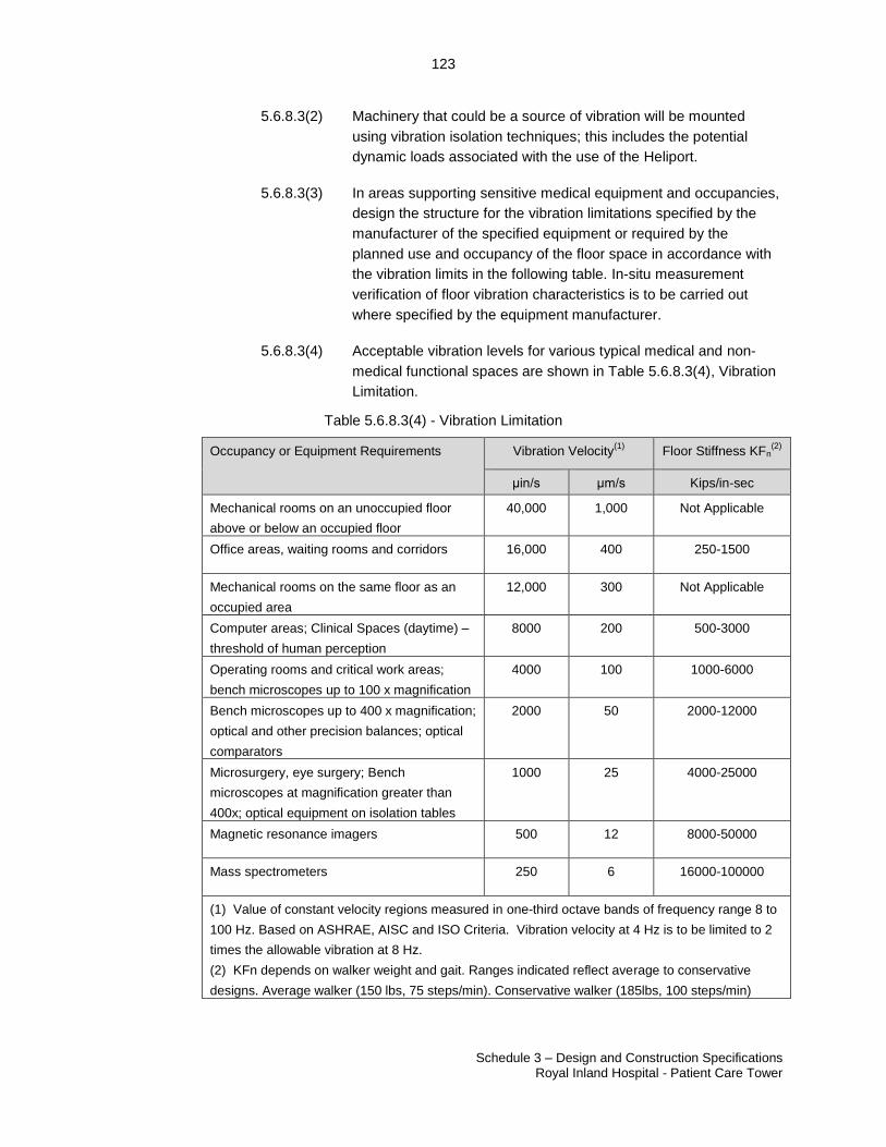
123
Schedule 3 – Design and Construction Specifications Royal Inland Hospital - Patient Care Tower
23507060.2
5.6.8.3(2) Machinery that could be a source of vibration will be mounted
using vibration isolation techniques; this includes the potential
dynamic loads associated with the use of the Heliport.
5.6.8.3(3) In areas supporting sensitive medical equipment and occupancies,
design the structure for the vibration limitations specified by the
manufacturer of the specified equipment or required by the
planned use and occupancy of the floor space in accordance with
the vibration limits in the following table. In-situ measurement
verification of floor vibration characteristics is to be carried out
where specified by the equipment manufacturer.
5.6.8.3(4) Acceptable vibration levels for various typical medical and non-
medical functional spaces are shown in Table 5.6.8.3(4), Vibration
Limitation.
Table 5.6.8.3(4) - Vibration Limitation
Occupancy or Equipment Requirements Vibration Velocity(1)
Floor Stiffness KFn(2)
μin/s μm/s Kips/in-sec
Mechanical rooms on an unoccupied floor
above or below an occupied floor
40,000 1,000 Not Applicable
Office areas, waiting rooms and corridors 16,000 400 250-1500
Mechanical rooms on the same floor as an
occupied area
12,000 300 Not Applicable
Computer areas; Clinical Spaces (daytime) –
threshold of human perception
8000 200 500-3000
Operating rooms and critical work areas;
bench microscopes up to 100 x magnification
4000 100 1000-6000
Bench microscopes up to 400 x magnification;
optical and other precision balances; optical
comparators
2000 50 2000-12000
Microsurgery, eye surgery; Bench
microscopes at magnification greater than
400x; optical equipment on isolation tables
1000 25 4000-25000
Magnetic resonance imagers 500 12 8000-50000
Mass spectrometers 250 6 16000-100000
(1) Value of constant velocity regions measured in one-third octave bands of frequency range 8 to
100 Hz. Based on ASHRAE, AISC and ISO Criteria. Vibration velocity at 4 Hz is to be limited to 2
times the allowable vibration at 8 Hz.
(2) KFn depends on walker weight and gait. Ranges indicated reflect average to conservative
designs. Average walker (150 lbs, 75 steps/min). Conservative walker (185lbs, 100 steps/min)
124
Schedule 3 – Design and Construction Specifications Royal Inland Hospital - Patient Care Tower
23507060.2
5.6.8.3(5) Design specific functional floor area structure for the current
planned occupancy vibration criteria as per Table 5.6.8.3(4)-
Vibration Limitation with the provision that for any floor containing
any clinical and inpatient occupancy, the vibration velocity for the
entire floor, excluding mechanical and electrical rooms, shall not
exceed 200 micro metres per second.
5.6.8.3(6) Refer to list of existing Laboratory Vibration Sensitive Equipment
located in the Data Room.
5.6.9 Durability
5.6.9.1 Design the structure and structural components of the New Facility for a
minimum 50-year life span.
5.6.9.2 Design the structure in accordance with all applicable material standards.
5.6.9.3 Design the structure and structural components of the New Facility to minimize
the effects of corrosion and deterioration due to the environment and use in
accordance with the following:
5.6.9.3(1) Adequate concrete crack control joints and expansion/contraction
joints. Caulk exposed joints;
5.6.9.3(2) High strength concrete mixes proportioned to CSA A23-1/A23-2
durability requirements for exposure class;
5.6.9.3(3) Reinforce concrete for crack control in accordance with the
serviceability and crack control requirements set forth in applicable
codes and standards. Repair all cracks exposed to public and
patient view and cracks within other areas exceeding 1.0mm in
width;
5.6.9.3(4) Hot-dip galvanize or use a quality two part epoxy paint system on
exterior exposed steel;
5.6.9.3(5) Chamfer exposed concrete edges; and
5.6.9.3(6) Add corrosion inhibitors to exterior reinforced concrete pavements
subject to vehicle traffic.
5.6.10 Medical equipment supports
5.6.10.1 Design and provide for support/anchorage of all Authority and Project Co
supplied equipment including vendor required seismic bracing. Medical
equipment will be supported, anchored, and braced to resist gravity, operational,
and seismic loads as required for the functional and service requirements for the
specific equipment.
125
Schedule 3 – Design and Construction Specifications Royal Inland Hospital - Patient Care Tower
23507060.2
5.6.10.2 The design for all equipment supports, anchorage, and bracing, including
medical, will be carried out by a qualified professional engineer registered in the
Province of British Columbia. Installations will be field reviewed by the design
engineer.
5.6.10.3 Performance criteria
5.6.10.3(1) Design floor and roof assemblies to support the gravity and
seismic loads for floor, wall, or ceiling-mounted medical equipment
included on the Appendix 2E Equipment List. Ensure that steel
content of structural members is compatible with equipment which
is sensitive to steel content of the surrounding structure;
5.6.10.3(2) Design the structure for the vibration limitations specified by the
manufacturer of the specified equipment or required by the
planned use and occupancy of the floor space and carry out in-situ
vibration testing when specified by the equipment manufacturer or
as required in Schedule 2 Design and Construction Protocols.
Where practical, the design of and supports for ceiling-mounted
equipment, such as radiology gantries, is to be universal for re-use
with future equipment installations; and
5.6.10.3(3) Drilled insert-type anchors for medical equipment supports and
anchorage are to be rated by the insert manufacturer for seismic
and cyclic loading applications and drop-in sleeve anchors shall
not be permitted.
5.6.11 Member Design Criteria
5.6.11.1 Design all floor and roof structural framing members to have sufficient strength
and stability so that the factored member resistance is equal to or greater than
the effects of the factored loads
5.6.11.2 Design all floor and roof structural framing members to have sufficient stiffness
so as to remain serviceable under the specified gravity loads. The deflection
criteria are presented in Section 5.6.7.
5.6.11.3 Lateral Load Resisting System Design Criteria
5.6.11.3(1) Design all structural framing members to have sufficient strength
and stability so that the factored member resistance is equal to or
greater than the effects of the factored lateral wind pressures or
seismic loads, whichever produces the more unfavourable effect;
5.6.11.3(2) Design all structural framing members to have sufficient stiffness
so as to remain serviceable under the specified wind pressures.
The maximum inter-storey drift under the 1 in 50 year service wind
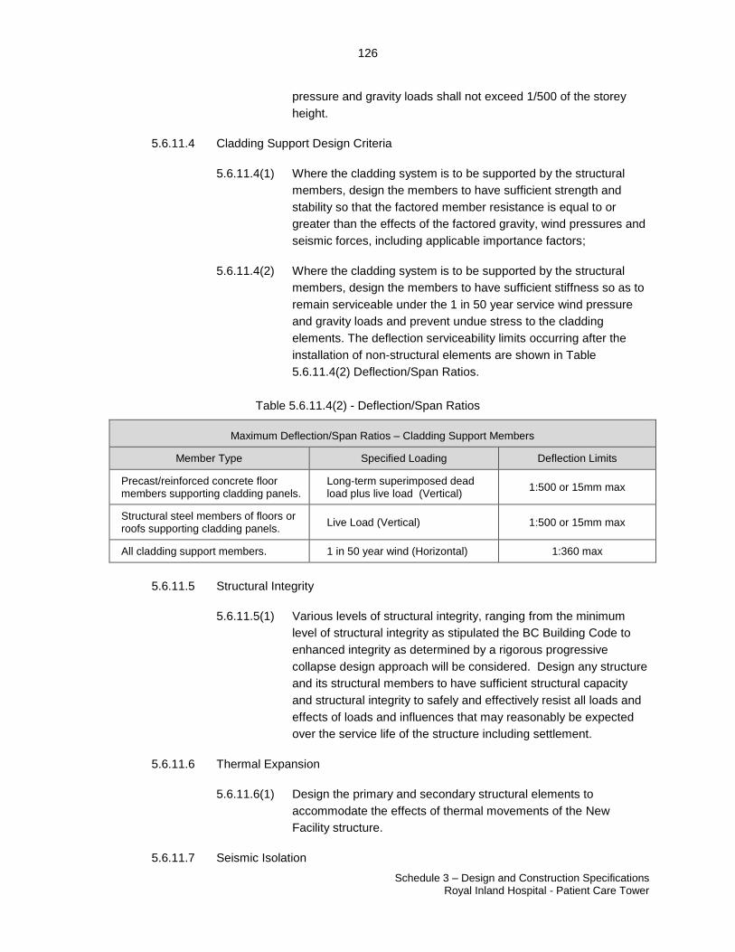
126
Schedule 3 – Design and Construction Specifications Royal Inland Hospital - Patient Care Tower
23507060.2
pressure and gravity loads shall not exceed 1/500 of the storey
height.
5.6.11.4 Cladding Support Design Criteria
5.6.11.4(1) Where the cladding system is to be supported by the structural
members, design the members to have sufficient strength and
stability so that the factored member resistance is equal to or
greater than the effects of the factored gravity, wind pressures and
seismic forces, including applicable importance factors;
5.6.11.4(2) Where the cladding system is to be supported by the structural
members, design the members to have sufficient stiffness so as to
remain serviceable under the 1 in 50 year service wind pressure
and gravity loads and prevent undue stress to the cladding
elements. The deflection serviceability limits occurring after the
installation of non-structural elements are shown in Table
5.6.11.4(2) Deflection/Span Ratios.
Table 5.6.11.4(2) - Deflection/Span Ratios
Maximum Deflection/Span Ratios – Cladding Support Members
Member Type Specified Loading Deflection Limits
Precast/reinforced concrete floor members supporting cladding panels.
Long-term superimposed dead load plus live load (Vertical)
1:500 or 15mm max
Structural steel members of floors or roofs supporting cladding panels.
Live Load (Vertical) 1:500 or 15mm max
All cladding support members. 1 in 50 year wind (Horizontal) 1:360 max
5.6.11.5 Structural Integrity
5.6.11.5(1) Various levels of structural integrity, ranging from the minimum
level of structural integrity as stipulated the BC Building Code to
enhanced integrity as determined by a rigorous progressive
collapse design approach will be considered. Design any structure
and its structural members to have sufficient structural capacity
and structural integrity to safely and effectively resist all loads and
effects of loads and influences that may reasonably be expected
over the service life of the structure including settlement.
5.6.11.6 Thermal Expansion
5.6.11.6(1) Design the primary and secondary structural elements to
accommodate the effects of thermal movements of the New
Facility structure.
5.6.11.7 Seismic Isolation
127
Schedule 3 – Design and Construction Specifications Royal Inland Hospital - Patient Care Tower
23507060.2
5.6.11.7(1) Design the structure to be completely independent from any
existing adjacent structures by a properly designed seismic
isolation joint which takes into account the lateral drifts of both the
new and adjacent existing structures in accordance with the
provisions of the BC Building Code.
5.7 Bariatric Design
5.7.1 Definition of obesity:
5.7.1.1 For the purposes of this document, bariatric individuals are considered to be
those within the range of 225 kg to 453 kg.
5.7.2 Bariatric Inpatient Room Requirements
5.7.2.1 Bariatric inpatient bedrooms will comply with CSA Z8000- 7.8.8.2.3
(Accommodation of Bariatric Persons). Requirements for MH&SU Psychiatric
Inpatient Unit – Patient Room, Private, Bariatric, may vary; refer to other
requirements of this Schedule;
5.7.2.2 The minimum dimension (in any direction) of the Bariatric bedroom will be
4500mm;
5.7.2.3 Clear space of at least 1500mm will be provided on three sides of the bed;
5.7.2.4 Sufficient clear space will be provided to accommodate large mobility aids and
other portable equipment as well as family space;
5.7.2.5 Service connections (e.g.: medical gas, electrical) will be spaced farther apart to
accommodate a wider bed;
5.7.2.6 The room will have a ceiling mounted patient lift and track system that can lift and
transport at least 454 kg. The track should extend to both sides of the bed;
5.7.2.7 The room will be equipped with handrails that can support at least 454kg; and
5.7.2.8 Patient room lights, temperature, and TV shall be controlled from the bed.
5.7.3 Washrooms for inpatient bedrooms for bariatric patients should be designed with the
following features:
5.7.3.1 Sink that can support at least a 363 kg downward force;
5.7.3.2 Wall hung toilets with elongated neck which will accommodate mobile bariatric
commodes to be mocked up for review by the Authority and adjusted if
necessary prior to approval for use;
128
Schedule 3 – Design and Construction Specifications Royal Inland Hospital - Patient Care Tower
23507060.2
5.7.3.3 Toilet position and height to enable a height adjustable bariatric commode to fit
over the toilet when the commode is positioned at the range of middle to
maximum height;
5.7.3.4 Distance from the toilet centre line to wall of 533mm to 610mm;
5.7.3.5 Clear space of at least 1118mm on one side of the toilet for transfer use;
5.7.3.6 Toilet paper dispenser mounted in a location where it can be easily reached by a
bariatric patient;
5.7.3.7 Equipped with grab bars that are sized and positioned for use by a bariatric
person and can support 363 kg downward force. Grab bars all extend behind and
beside the toilet.
5.7.3.8 Full height waterproof wall covering system on all four walls.
5.7.3.9 Shower area that:
5.7.3.9(1) is open to the toilet area, with no floor lip, and with floor sloped to a
drain;
5.7.3.9(2) has a minimum dimensions of 1220mm x 1520mm; and
5.7.3.9(3) is equipped with a moveable/portable shower seat and grab bars.
A privacy curtain will be provided inside the door to the Patient
Room, Private, Bariatric.
5.8 Renovations
5.8.1 General Requirements
5.8.1.1 Renovations in the existing RIH Campus work areas described in Appendix 2I
shall be completed to meet the same standards and performance specifications
as described in Schedule 3.
5.8.1.2 Project Co shall be responsible for relocation of the existing RIH retail café
located adjacent to the existing Level 2 entry and traffic circle, including all
equipment. Make Good the existing retail café area including all finishes and
capping existing services.
5.8.1.3 Project Co shall be responsible for design of Post Anesthetic Recovery Room
(PARR) Area and Daycare Surgery in the existing Hospital to be located on Level
4 North and Level 4 West respectively. Demolition, construction and
commissioning of Post Anesthetic Recovery Room (PARR) Area and Daycare
Surgery will be part of Phase 2 Renovation Services.
5.8.1.4 The design of the Post Anesthetic Recovery Room (PARR) Area and Daycare
Surgery renovation area shall meeting the following criteria:
129
Schedule 3 – Design and Construction Specifications Royal Inland Hospital - Patient Care Tower
23507060.2
5.8.1.4(1) Mechanical Requirements
5.8.1.4(1)(a) New Facility ventilation system shall supply the
renovation areas. Requirement for 20% spare
capacity shall not apply to the ventilation mains in
the renovated areas. Provide low level exhaust to
collect exhaled anesthetic gases.
5.8.1.4(1)(b) Provided new active radiant panels on all exterior
walls within the renovated areas. Existing hydronic
system serving the existing radiant panels may be
utilized if Project Co demonstrates to the Authority
the system has adequate capacity. Each space shall
have individual control of its dedicated radiant panel.
5.8.1.4(1)(c) Hydronic heating for ventilation air reheat shall be
supplied from the New Facility. The mains shall be
sized for the design load, additional spare capacity
is not required in this system.
5.8.1.4(1)(d) New Facility BMS shall be extended to control and
monitor the new components in the renovation
areas. Provide all components and programing for a
fully operational system complete with up to date
graphics. All requirements of Section 7.8 shall apply.
5.8.1.4(1)(e) Project Co shall be responsible for domestic cold,
hot, and recirculation water systems and
connections. Based on initial review by the Authority,
the existing systems are anticipated to be adequate
to serve the requirements, but Project Co shall
confirm.
5.8.1.4(1)(f) Provide new water pipe distribution to serve the
fixture requirements. Comply with all requirements
of Section 7.3 except the domestic hot water
generation requirements.
5.8.1.4(1)(g) Fixtures to match those used in the New Facility and
comply with all requirements of Section 7.8.
5.8.1.4(1)(h) Project Co is responsible for relocation of all existing
services as required to serve the renovation areas
including, required rework of existing plumbing
(sanitary, storm, and venting), heating, cooling,
medical gases and control wiring or pneumatics in
the ceilings below and all reconnection to existing
systems on floors above.
130
Schedule 3 – Design and Construction Specifications Royal Inland Hospital - Patient Care Tower
23507060.2
5.8.1.4(1)(i) Provide sprinkler system installed in accordance with
Section 7.2 of this schedule with the exception of
20% spare capacity in design which will not be
required for this area.
5.8.1.4(1)(j) Medical gases shall be supplied from the New
Facility, 20% spare capacity in the mains is not
required in renovated areas. To accommodate for
future connection of the existing OR’s in the RIH
Campus to the AGSS, extend the AGSS piping
through the PARR space and provide valve and
capped connection in the ceiling of the existing
North Tower adjacent to the New Facility
Patient/Service elevators. Piping shall be sized to
accommodate the anticipated load of the existing
OR’s.
5.8.1.4(2) Electrical Requirements
5.8.1.4(2)(a) Project Co is responsible for relocation of all existing
electrical and communication services as required to
serve the renovated areas. This scope includes;
power, data, lighting, emergency lighting, life safety,
nurse call, fire alarm, IP Video Surveillance, access
control, patient entertainment, video intercom, staff
duress, and security. Functional Component entry
doors to be secured after hours and equipped with a
video intercommunication system connected to the
PARR Care Team Station. Provide remote release
of the entry doors through the access control system
from the PARR Care Team Station.
5.8.1.4(2)(b) Project Co is responsible for all new electrical and
communication services as required to serve the
renovated areas. This scope includes; power, data,
lighting, emergency lighting, life safety, nurse call,
fire alarm, IP Video Surveillance, access control,
patient entertainment, video intercom, staff duress,
and security.
5.8.1.4(2)(c) Provide new LED lighting fixtures and lighting control
for the renovated areas. Fixtures to match those
used in the New Facility and shall comply with all
requirements of Schedule 3. Refer to Appendix 3C
Room Data Sheets for the specific lighting
requirements for each area. All requirements of
Section 7.8.12 Lighting shall apply.
131
Schedule 3 – Design and Construction Specifications Royal Inland Hospital - Patient Care Tower
23507060.2
5.8.1.4(2)(d) Provide a complete communications system for the
renovated areas. Communications systems to match
those used in the New Facility and shall comply with
all requirements of Schedule 3. Refer to Appendix
3C Room Data Sheets for the specific quantity of
telecommunications outlets and data ports for each
area. All communications system requirements shall
be in accordance with the Authority’s most recent
version of Communications Infrastructure Standards
& Specifications Appendix 3E. All requirements of
Sections 7.9 Communications (Division 27) shall
apply.
5.8.1.4(2)(e) Provide new electrical distribution, metering,
emergency power, UPS, wiring method and
materials and electrical equipment and devices for
the renovated areas. Electrical distribution, electrical
equipment and devices match those used in the
New Facility and shall comply with all requirements
of Schedule 3. Refer to Appendix 3C Room Data
Sheets for the specific power requirements for each
area. All requirements of Section 7.8 Electrical
(Division 26) shall apply.
5.8.1.4(2)(f) Provide a complete Electronic Safety and Security
system for the renovated areas. Electronic Safety
and Security system to match those used in the New
Facility and shall comply with all requirements of
Schedule 3. Refer to Appendix 3C Room Data
Sheets for the specific requirements for each area.
All Electronic Safety and Security system
requirements shall be in accordance with the
Authority’s most recent version of Communications
Infrastructure Standards & Specifications Appendix
3E. All requirements of Sections 7.10 Electronic
Safety and Security system shall apply.
5.9 Interim Post Anesthetic Recovery Room (PARR)
5.9.1 General Requirements
5.9.1.1 Project Co shall design and construct the Un-Equipped Hybrid Operating Room
as one contiguous interim PARR space for use by the Authority until the Level 4
PARR space is completed as Part of Phase 2 Renovation Services, refer to
Appendix 4B Renovation Services.
132
Schedule 3 – Design and Construction Specifications Royal Inland Hospital - Patient Care Tower
23507060.2
5.9.1.2 The Authority will operate both their existing PARR located in the existing
Hospital on Level 4 West, injunction with the interim PARR provided in the New
Facility. The interim PARR will be utilized to provide services to the most critical
post-operative patients.
5.9.1.3 Project Co shall design and construct the interim PARR space to meet the
following requirements:
5.9.1.3(1) In accordance with Appendix 3K Interim PARR Room Data Sheet;
5.9.1.3(2) To fulfill the Authority’s requirements to operate a fully functional
PARR unit for the interim period from Service Commencement
until the Level 4 North PARR Renovation Services are complete
and in operation by the Authority;
5.9.1.3(3) Minimize the renovations required to convert the interim PARR
area into the Un-Equipped Hybrid Operating Rooms;
5.9.1.3(4) Provide one contiguous interim PARR space separated by
partitions from adjacent spaces such as the Sterile Core and
Restricted Corridor. The wall which demises the two Un-Equipped
Hybrid Operating Rooms shall be open in the interim condition and
constructed to meet the final Operating Room requirements once
permanent Level 4 North PARR Renovation Services are complete
and in operation by the Authority;
5.9.1.3(5) Provide a minimum eight total stretcher bays sized at a minimum
2000mm wide x 2600mm long. Ceiling height shall be as per
5.4.7.6(3) Ceiling heights in OR’s;
5.9.1.3(6) Arrange all stretcher bays in pairs, with a nursing station and
patient service column in-between the bays located near the head
of the patient. Patients will face the wall with the head towards the
center of the room. Patient service columns shall be temporary,
Millwork sized at minimum 600mm wide x 1370mm long and
provide the headwall features described in Appendix 3K Interim
PARR Room Data Sheet.
5.9.1.3(7) Other features to be incorporated into the design of the interim
PARR include:
5.9.1.3(7)(a) Portable privacy curtains around each stretcher bay;
5.9.1.3(7)(b) Portable lift shall be used to transfer patients when
required;
5.9.1.3(7)(c) Two patient monitors at each patient service column,
one per stretcher bay;
133
Schedule 3 – Design and Construction Specifications Royal Inland Hospital - Patient Care Tower
23507060.2
5.9.1.3(7)(d) Workstation with computer centrally located for
nursing staff with line of sight to each stretcher bay;
5.9.1.3(7)(e) Workstation with computer at each patient service
column, one per stretcher bay;
5.9.1.3(7)(f) Counter top automated drug dispensing unit;
5.9.1.3(7)(g) Blanket warmer.
5.9.1.4 Project Co shall be responsible to provide all services required for the Authority’s
interim PARR equipment, refer to Schedule 2 Appendix 3K Interim PARR Room
Data Sheet.
5.9.1.5 Record drawings of the New Facility provided to the Authority by Project Co prior
to Service Commencement, shall reflect the interim PARR layout. Once the
Authority’s use of the interim PARR is complete, revised Record drawings shall
be provided to document the final Operating Room layout.
5.9.2 Mechanical Requirements
5.9.2.1 The interim PARR will utilize the ceiling ventilation infrastructure provided for the
Un-Equipped Hybrid Operating Rooms.
5.9.2.2 HVAC system and associated diffuser and return grille design shall be installed
as per the final Operating Room configuration and function. CSA Z317.2 does
not permit the recirculation of PARR air. While the space is utilized as PARR, air
shall be exhausted, if Project Co’s design utilizes a return air system for the
Operating Rooms, the return air from the interim PARR shall be intercepted in
the Mechanical Room and discharged to the outdoors with a dedicated exhaust
fan system. This fan system shall contain N+1 redundancy and be served by
delayed vital power. Once the Authority’s use of the interim PARR is complete
and the transition to Operating room is underway, the dedicated exhaust system
shall be removed and the return system configured as per final Operating Room
design. All ductwork, hangers, controls, and equipment made redundant by the
transition shall be removed.
5.9.2.3 The medical gas piping shall be sized to accommodate the requirements of the
interim PARR and the final Operating Room function. Medical gases shall be
installed up to the future boom connections and terminated with dual port valves
and connections as required for the booms in the future during the final
construction of the Operating Rooms. Provide connections complete with dual
port valves between the zone valves and boom connections to serve the interim
PARR medical gases as described in Appendix 3K Interim PARR Room Data
Sheet. Once the Authority’s use of the interim PARR is complete, the space will
be transitioned back to Operating Rooms. During this transition, Project Co shall
remove the medical gas piping from the patient service column back to the
connections and valves, then cap the runouts in the ceiling within 150 mm of the
134
Schedule 3 – Design and Construction Specifications Royal Inland Hospital - Patient Care Tower
23507060.2
purge port. Project Co shall remove all hangers and supports made redundant by
the removal of the interim medical gas piping.
5.9.2.4 Project Co shall provide domestic cold, hot, and recirculation water systems and
connections to the hand hygiene sinks as noted in Appendix 3K Interim PARR
Room Data Sheet. Provide isolation valves on the branches feeding the fixture
outside of the space. Once the Authority’s use of the interim PARR is complete,
the water piping shall be removed back to these valves and capped for future
use. Remove all redundant water piping and associated hangers and supports
from the Operating Rooms. No water pipe shall remain in the ceiling space.
5.9.2.5 Provide sanitary and vent piping to serve the hand hygiene sinks. Once the
Authority’s use of the interim PARR is complete, the vent piping shall be removed
to a location outside of the Operating Room ceiling and capped for future use.
The sanitary piping shall be removed and capped below the floor slab in the
ceiling below for future connection.
5.9.2.6 Fire sprinklers shall be installed as required to serve the final Operating Room
layout. Project Co shall provide additional heads as required for the interim
PARR layout and patient service columns. Once the Authority’s use of the
interim PARR is complete, Project Co shall complete remedial work as required
to return the fire protection layout to the final Operating Room design.
5.9.2.7 The BMS device locations shall be located on the finished walls provided for the
interim PARR function so that no devices require installation in the demising wall
which will be installed when the PARR function has ended and the rooms are
being divided into the final two Operating Room configurations. Project Co shall
provide all required programing to operate the space as an interim PARR and
then make all required changes to the Operating Room function once the interim
PARR phase is complete. The BMS graphic’s shall reflect the use and layout of
the space and will be updated by Project Co once the Authority’s use of the
interim PARR is complete.
5.9.2.8 Project Co shall commission the space as an interim PARR and provide
commissioning and balancing reports prior to occupancy. Once the Authority’s
use of the interim PARR is complete, the rooms will be rebalanced and
commissioned by Project Co as Operating Rooms and a demonstration of room
operation provided to the Authority by Project Co prior to the Authority’s
acceptance of the space for its intended use.
5.9.3 Electrical Requirements
5.9.3.1 The interim PARR will utilize the same electrical infrastructure as provided for the
Un-Equipped Hybrid Operating Rooms as once the Authority’s use of the interim
PARR is complete, the space will be transitioned back to Hybrid Operating
Rooms.
135
Schedule 3 – Design and Construction Specifications Royal Inland Hospital - Patient Care Tower
23507060.2
5.9.3.2 The interim PARR lighting design shall be installed with electrical lighting
systems as per the final Operating Room configuration and function. However,
one additional wall or ceiling mounted exam light shall be provided and installed
for each PARR bay as directed by the Authority.
5.9.3.3 Lighting shall comply with all the requirements of Schedule 3 and in particular to
all requirements noted in section 7.8.12.2(26) Operating/Surgical and Procedure
Rooms and as referenced in Appendix 3K Interim PARR Room Data Sheet.
5.9.3.4 All requirements of Section 7.8.12 Lighting shall apply to the interim PARR.
5.9.3.5 Project Co shall provide the same electrical lighting infrastructure as required for
in the Un-Equipped Hybrid Operating Rooms.
5.9.3.6 Provide for all final electrical lighting systems and terminate all final services
connections within junction boxes, and pull boxes.
5.9.3.7 Provide all connections as required for the final construction of the Operating
Rooms. Once the Authority’s use of the interim PARR is complete, Project Co
shall convert the spaces to Operating Rooms. All lighting, seismic supports,
conduit, conductors, junction boxes, hangers, and equipment made redundant by
the transition shall be removed by Project Co.
5.9.3.8 The interim PARR electrical power and systems design shall be as in accordance
with the final Operating Room configuration and function. However, the interim
PARR will utilize service columns to service the interim PARR bays. Project Co
shall provide all electrical power and systems including emergency power, UPS
power and normal power outlets, and electrical equipment and devices to comply
with all the specific power requirements of Schedule 3 and as referenced in
Appendix 3K Interim PARR Room Data Sheet.
5.9.3.9 All requirements of Section 7.8 Electrical (Division 26) shall apply to the interim
PARR. Project Co shall provide the same electrical power and systems
infrastructure as required in the Un-Equipped Hybrid Operating Rooms.
5.9.3.10 Provide for all final electrical power and systems and terminate all final services
connections within junction boxes, and pull boxes c/w terminal strips. Provide all
connections as required for the final construction of the Operating Rooms. Once
the Authority’s use of the interim PARR is complete, Project Co shall convert the
spaces to Operating Rooms. All power, systems, conduit, conductors, junction
boxes, supports, and equipment made redundant by the transition shall be
removed.
5.9.3.11 The interim PARR communications systems design shall be as in accordance
with the final Operating Room configuration and function. However, the interim
PARR will utilize service columns to service the interim PARR bays. Project Co
shall provide all communication systems to comply with all requirements of
Schedule 3 and as referenced in Appendix 3K Interim PARR Room Data Sheet.
136
Schedule 3 – Design and Construction Specifications Royal Inland Hospital - Patient Care Tower
23507060.2
5.9.3.12 All requirements of Sections 7.9 Communications (Division 27) shall apply. All
communications system requirements shall be in accordance with the Authority’s
most recent version of Communications Infrastructure Standards & Specifications
Appendix 3E.
5.9.3.13 Project Co shall provide the same communications infrastructure as required in
the Un-Equipped Hybrid Operating Rooms. Provide for all final communications
systems and terminate all final services connections within junction boxes, and
pull boxes c/w terminal strips. Provide all connections as required for the final
construction of the Hybrid Operating Rooms. Once the Authority’s use of the
interim PARR is complete, Project Co shall convert the spaces to Hybrid
Operating Rooms. All communications systems, conduit, cabling, junction boxes,
supports, and equipment made redundant by the transition shall be removed.
5.9.3.14 The interim PARR Electronic Safety and Security system design shall be as in
accordance with the final Operating Room configuration and function. Project Co
shall provide all Electronic Safety and Security systems to comply with all
requirements of Schedule 3 and as referenced in Appendix 3K Interim PARR
Room Data Sheet.
5.9.3.15 All Electronic Safety and Security system requirements shall be in accordance
with the Authority’s most recent version of Communications Infrastructure
Standards & Specifications Appendix 3E.
5.9.3.16 All requirements of Sections 7.10 Electronic Safety and Security system shall
apply. Provide for all final Electronic Safety and Security systems and terminate
all final services connections within junction boxes, and pull boxes c/w terminal
strips. Provide all connections as required for the final construction of the
Operating Rooms. Once the Authority’s use of the interim PARR is complete,
Project Co shall convert the spaces to Operating Rooms. All Electronic Safety
and Security systems, conduit, cabling, junction boxes, supports, and equipment
made redundant by the transition shall be removed.
5.9.3.17 Project Co shall commission the space as an interim PARR and provide
commissioning and user group training for all electrical systems. Provide
verification of light levels, lighting commissioning, data verification, fire alarm
verification, and CSA Z32 room reference bonding testing reports prior to
occupancy. Once the Authority’s use of the interim PARR is complete, the rooms
will be re-commissioned by Project Co as Operating Rooms and a demonstration
of room operation will be provided to the Authority by Project Co prior to the
Authority’s acceptance of the space for its intended use. Once the interim PARR
phase is complete, the Fire Alarm graphical interface shall be updated to reflect
the final layout of the space.
137
Schedule 3 – Design and Construction Specifications Royal Inland Hospital - Patient Care Tower
23507060.2
PART 6. FACILITIES CONSTRUCTION SUBGROUP SPECIFICATIONS
6.1 Procurement and Contracting Requirements (Division 1) – NOT USED
6.2 Existing Conditions (Division 2)
6.2.1 Refer to Section 6.8 of Schedule 2 Design and Construction Protocols regarding the
Geotechnical Report.
6.2.2 Project Co will visit the Site, and at its option and prior to the execution of the Project
Agreement, may perform further sub-surface investigation, drilling and sampling, material
testing, exploratory excavations, and pre-construction monitoring, at its own expense and
after receiving written permission from the Authority.
6.3 Concrete (Division 3)
6.3.1 Basic Requirements
6.3.1.1 Refer to Section 2.1 Standards. The list of technical references is not intended to
be a complete list of applicable standards. Design and construction will comply
with applicable standards and practices whether listed in this section or not.
6.3.2 Overriding Principles
6.3.2.1 Design and construct cast in place or precast concrete of properties required for
the intended use in accordance with the requirements of all applicable codes and
specifications for the applicable concrete exposure class and to maximize the fly
ash content of the mix. All cast in place concrete shall be vibrated or densified in
an approved manner by a competent place and finish contractor.
6.3.2.2 Honeycombing and bug holes will be repaired immediately under the direction of
the Structural Engineer.
6.3.2.3 Use wood formwork or sonotube type form for all cast in place concrete.
6.3.3 Quality Requirements
6.3.3.1 Cause cast in place concrete and concrete materials to be inspected and tested
by a CSA certified testing laboratory.
6.3.3.2 Cause precast concrete materials and workmanship to be inspected and tested
by the precast concrete contractor as part of its quality control program in
accordance with all applicable standards.
6.3.4 Performance Criteria
6.3.4.1 Finish concrete floors with a smooth, dense, steel trowel finish with a Class A
Flatness Classification in accordance with CSA A23.1.
138
Schedule 3 – Design and Construction Specifications Royal Inland Hospital - Patient Care Tower
23507060.2
6.3.4.2 Repair cracks in concrete floors and walls to suit the floor finish and long-term
serviceability requirements of the floor.
6.3.4.3 Water proof foundation walls surrounding occupied spaces to prevent
groundwater ingress. Construction joints will have purpose-made water stops. A
perimeter footing drainage system will be installed around the exterior of the
below grade spaces.
6.3.4.4 Architectural Concrete will comply with CAN/CSAA23.1 to minimize honey
combing or patching. Architectural Concrete shall have smooth and flat surface
of uniform color with sandblast finish including sealer throughout and anti-graffiti
coating where in potential contact with human touch. Repairs to be under the
direction of the structural Engineer of Record.
6.4 Masonry (Division 4)
6.4.1 Basic Requirements
6.4.1.1 Masonry design and construction that meets or exceeds current Canadian
standards and practices as set out in this section, may be considered for building
elements and systems.
6.4.1.2 Masonry design and construction will comply with all applicable codes and
standards including CSA S304, CSA A371, the BC Building Code, and the
standards listed in Section 2.1 Standards.
6.4.1.3 Masonry construction may be considered for exterior walls and walls systems
where permanence of finishes, both visually and functionally, and ease of
maintenance are primary considerations in the exterior fabric of the Building.
6.4.1.4 Masonry construction may be considered for interior walls and wall systems
when priorities include permanence and maintenance, sound transmission
control, fire resistance and separation requirements and security.
6.4.1.5 Face work shall be laid plumb and true with all joints consistent in both width and
colour.
6.4.1.6 Provide masonry sealers to all exterior masonry.
6.4.2 Concrete Masonry Units
6.4.2.1 Concrete unit masonry may be considered for both independent exterior walls
and in exterior wall systems as a structural backing to other finish materials or
systems.
6.4.2.2 Concrete unit masonry for interior applications may be considered as an
integrally finished material, as a base for applied finish and as a structural
backing to other finish systems.
139
Schedule 3 – Design and Construction Specifications Royal Inland Hospital - Patient Care Tower
23507060.2
6.4.2.3 Painted or unpainted concrete unit masonry shall not be used as an exposed
finish in clinical or public areas.
6.4.2.4 Where concrete unit masonry is used as the exposed finish all exposed corners
will be radiused.
6.4.2.5 Masonry design and construction will comply with Canadian Masonry Contractors
Association (CMCA) Masonry Practices Manual, CSA-S304, and all applicable
standards including CSA-A371.
6.4.3 Brick Masonry
6.4.3.1 Exterior wall systems comprising brick masonry as a finish veneer to concrete,
concrete masonry or metal framing will be a rain screen or cavity wall system.
Exterior brick veneer cladding support is to be designed as a complete system to
include all loading and attachments to all structural components including
adjacent concrete, miscellaneous steel, load bearing steel stud framing, lateral
bracing and brick ties and will be carried out by a qualified professional engineer
registered in the Province of British Columbia. Installations will be field reviewed
by the design engineer.
6.4.3.2 Brick masonry below grade for exterior applications is not permitted.
6.4.3.3 Brick masonry in interior applications is to have integral finish and construction
compatible with the Authority’s infection prevention and control requirements.
6.4.4 Stone Masonry
6.4.4.1 Stone masonry may be considered as a finish veneer to concrete walls or
concrete masonry walls. Exterior wall systems in such applications will be a rain
screen or cavity wall system.
6.4.4.2 Stone will be sound, hard and durable, well-seasoned and of uniform strength,
colour and texture, and free of quarry sap, flaws, seams, sand holes, iron pyrites
or other mineral or organic defects.
6.4.4.2(1) Manufactured stone products shall not be used.
6.5 Metals (Division 5)
6.5.1 Basic Requirements
6.5.1.1 Structural steel, steel deck, miscellaneous metal fabrications, and cold-formed
steel stud design and construction that meets or exceeds current Canadian
standards and practices, including BC Building Code, as set out in this section,
may be considered for Building elements and systems.
6.5.2 Performance Criteria
140
Schedule 3 – Design and Construction Specifications Royal Inland Hospital - Patient Care Tower
23507060.2
6.5.2.1 Design structural steel, steel deck, and cold-formed steel stud systems to comply
with the deflection and vibration criteria outlined in Section 5.6 (Structural
Design).
6.5.2.2 Erection tolerances for steel construction will be in accordance with CSA S16
Clause 29.3.
6.5.2.3 For steel floor and roof construction, the deflection of steel beams, joists, and
girders due to the wet weight of concrete topping slabs is to be considered.
Topping slab thickness may have to vary to maintain floor levelness tolerances.
The additional concrete ponding weight is to be considered in the design of the
structure.
6.5.2.4 Concrete topping slabs will be finished with a smooth, dense, steel trowel finish
with a Class A Flatness Classification in accordance with CSA A23.1. Thin
overlay toppings to level floors shall not be used to level floors.
6.5.2.5 Pay special attention to crack control of concrete topping slabs on steel deck to
avoid random surface shrinkage cracking and radial cracking around re-entrant
corners and special attention to curing is required for concrete topping slabs on
metal deck. As a minimum, the following details and procedures will be
implemented:
6.5.2.5(1) Minimize wet weight deflections of steel decking and supporting
structure;
6.5.2.5(2) Where practical, place concrete in alternate bays. Avoid placing
large areas at one time;
6.5.2.5(3) Use concrete topping with a low design slump. Add
superplasticizer to increase slump for placing and finishing; and
6.5.2.5(4) Provide extra topping slab reinforcement around openings,
columns, and at corners.
6.5.2.6 Cracks in concrete topping slabs will be repaired to suit the floor finish and long-
term serviceability requirements of the floor.
6.5.2.7 Steel floor/roof decking is to be wide rib profile for ease of attachment of current
and future services, equipment, and fixtures using drilled insert expansion
anchors into the bottom of the deck ribs.
6.5.2.8 Steel floor/roof decking plus the concrete topping slab thickness is to satisfy the
requirements of a ULC-rated assembly meeting the BC Building Code fire rating
requirements. Spray on or applied fireproofing material is not to be used to
achieve required floor deck fire rating.
141
Schedule 3 – Design and Construction Specifications Royal Inland Hospital - Patient Care Tower
23507060.2
6.5.2.9 Fire proof structural steel floor/roof framing and supporting members to meet the
fire rating requirement. Spray on fire proofing applications, which will be tamped
while wet to densify product, will be used for floor and roof beams and girders,
complete with an applied sealer creating a dense non-friable surface, for ease of
future attachment of services and equipment.
6.5.3 Structural Steel
6.5.3.1 Quality Requirements
6.5.3.1(1) Quality assurance testing and monitoring of workmanship to be
carried out by an approved testing laboratory using testing
procedures as specified in the CAN/CSA standards listed in
Section 2.1 of this Schedule, including CSA S16, to verify
soundness of representative shop and field welds. Test all full
strength welds.
6.5.3.1(2) Material quality including sourcing and welding quality will be
monitored by an independent testing agency paid by Project Co.
6.5.3.1(3) The specification for preparation and painting of Structural Steel
components will conform to the Master Painters Institute (MPI)
Standards.
6.5.3.1(4) Exterior exposed structural steel will be hot dipped galvanized to
600 g/m2 or painted with a quality two part epoxy paint system.
6.5.4 Cold-Formed Metal Framing
6.5.4.1 Overriding Principles
6.5.4.1(1) Load bearing and non-load bearing steel studs may be considered
as a component of the exterior wall systems to support exterior
wall finishes and form an integral part of the perimeter envelope.
6.5.4.1(2) Rain screen walls utilizing cold-formed metal framing will be non-
load bearing.
6.5.4.1(3) Load bearing steel studs will be independent of the principle
structural system.
6.5.4.1(4) Utilize cold-formed metal framing systems as part of rain screen
systems, including tested air barrier assemblies.
6.5.4.2 Quality Requirements
6.5.4.2(1) Design, detail and construct load bearing steel stud design and
construction to comply with all applicable CAN/CSA standards.
142
Schedule 3 – Design and Construction Specifications Royal Inland Hospital - Patient Care Tower
23507060.2
6.5.4.2(2) Cold –formed metal framing design will be carried out by a
Professional Engineer registered in the Province of British
Columbia; construction will comply with CSA-S136. Field reviews
of the cold-formed metal framing installation will be carried out by
the cold formed metal framing design engineer.
6.5.4.2(3) The steel stud manufacturer will be certified in accordance with
CSSBI Standard 30M-06 and all applicable CAN/CSA standards
including CSA-A660.
6.5.4.2(4) Conform to the Association of Wall and Ceiling Contractor’s
Specification Standards Manual (AWCC).
6.5.4.3 Performance Requirements
6.5.4.3(1) Limit maximum deflection under specified wind loads to L/360
(including masonry veneers), unless a smaller maximum deflection
is specifically required due to wall finishes.
6.5.4.3(2) Design components to accommodate erection tolerances of the
structure.
6.5.4.3(3) Design wind bearing stud end connections to accommodate
floor/roof deflections and to ensure that studs are not loaded
axially.
6.5.4.3(4) Design steel studs to take into account the anchorage of other
materials being supported including: sub-girts supporting metal
cladding and composite panels, soffit finishes and the provision of
lateral support at window heads.
6.5.5 Miscellaneous Metals
6.5.5.1 Quality Requirements:
6.5.5.1(1) Primers and paints of miscellaneous metals will conform to Master
Painters Institute (MPI) Architectural Specification Standards
Manual.
6.5.5.1(2) Exterior elements will be hot dipped galvanized with 600 g/m2 to
CAN/CSA – G164 or painted with a quality two part epoxy paint
system.
6.5.5.2 Performance Requirements:
6.5.5.2(1) Welding to be in accordance with CSA W59-13.
6.5.6 Modular Ceiling System
143
Schedule 3 – Design and Construction Specifications Royal Inland Hospital - Patient Care Tower
23507060.2
6.5.6.1 Provide, as required, a special, modular structural ceiling system (such as
Unistrut), attached to the main structure, and designed to support all ceiling
mounted equipment indicated in Schedule 2, Appendix 2E Equipment and
Furniture.
6.6 Wood Plastics and Composites (including Millwork) (Division 6)
6.6.1 Basic Requirements
6.6.1.1 Do not use products containing added urea formaldehyde in the Building.
6.6.1.1(1) The intent is to prevent the use of wood product such as particle
board made with formaldehyde-based resins and binders.
6.6.1.2 Provide rough carpentry, wood backing materials, backing boards for mechanical
rooms and electrical/communication rooms (minimum 2400mm AFF), roof
sheathing, copings, cant strips, finish carpentry and architectural woodwork,
including exterior fascia’s, cabinets, casework (excluding Sterile Core and OR
casework, which is included in Division 12), frames, panelling, ceiling battens,
trim, installation of doors and hardware, and other wood-related products and
applications as required:
6.6.1.2(1) To meet the requirements of this Schedule, support functionality as
defined in Appendix 3A Clinical Specifications and Functional
Space Requirements and as required for operation of the New
Facility;
6.6.1.2(2) As required for wood products exposed to view in finished interior
and exterior installations.
6.6.1.3 Provide solid polymer fabricated surfacing as noted in Appendix 3C Room Data
Sheets including:
6.6.1.3(1) All counters that incorporate sinks, with the exception of where
counters are also stainless steel such as Soiled Utility Rooms and
Surgical Services Support areas;
6.6.1.3(2) All Protection Services/Volunteers Kiosks, Reception Desks,
Cashier Wickets, Registration Cubicles, Control Desks and all
Operating Room nursing and physician Millwork workstations,
Care Team Stations, Learners, Observation Alcoves and Unit
Clerks;
6.6.1.3(3) Other areas as required to create surfaces that provide antiseptic
or clean characteristics, special or regular maintenance, and
resistance to caustic action of chemicals or agents used by the
Authority.
144
Schedule 3 – Design and Construction Specifications Royal Inland Hospital - Patient Care Tower
23507060.2
6.6.1.4 Provide acrylic plastic, stainless steel or epoxy products as required for wall
cladding, wall protection, corner protection, casework finishing, trims, ornamental
elements, and other applications to achieve a quality of interior finish suitable for
use by patients and staff.
6.6.1.5 Use pressure treated wood for exterior exposed wood.
6.6.1.6 MH&SU Psychiatric Inpatient Unit Storage, Patient Belongings shall have 30
individually lockable Millwork cabinets to store up to 30 Rubbermaid bins.
Millwork design to be determined through Schedule 2 Appendix 2C Review
Procedure.
6.6.1.7 For the MH&SU Child and Adolescent Mental Health Crisis Intervention Program,
provide individually lockable Millwork cabinets in the Alcove Patient Belongings.
Millwork design to be determined through Schedule 2 Appendix 2C Review
Procedure.
6.6.1.8 For areas requiring mail slots as per Appendix 3C Room Data Sheets, provide
number of mail slots as determined through Schedule 2 Appendix 2C Review
Procedure.
6.6.2 Performance Criteria
6.6.2.1 Finish Carpentry, Millwork and Architectural Woodwork
6.6.2.1(1) Conform to Architectural Woodwork Standards, First Edition, as
issued by Architectural Woodwork Manufacturer’s Association of
Canada (AWMAC). Typically comply with Quality Standards
Manual for minimum “Custom Grade,” and Door and Hardware
Institute (DHI) standards for the design, fabrication, materials,
installation, and workmanship of finish carpentry and architectural
woodwork;
6.6.2.1(2) All bottoms of sink cabinet boxes and areas that may come into
contact with water shall have a marine-grade plywood substrate.
Do not use fiberboard or particle board;
6.6.2.1(3) Use marine-grade plywood substrate for countertops. Do not use
fiberboard or particle board;
6.6.2.1(4) For Millwork cabinets, seal all wood surfaces and edges. All door,
drawer and other exposed Millwork edges will have applied a PVC
edge strip, heat applied. All PVC edging to match tone of adjacent
Millwork. There will be no P-Lam to P-Lam edges. P-Lam
countertops to be minimum 38 – 40 mm thick and have minimum
38 – 40 mm thick hardwood edge with 7 mm radius double round
top and bottom, stain and finish to match counter;
145
Schedule 3 – Design and Construction Specifications Royal Inland Hospital - Patient Care Tower
23507060.2
6.6.2.1(5) Comply with the requirements of credit 4.4 (Indoor Environmental
Quality, Low-Emitting Materials: Composite Wood and Laminate
Adhesives) of the LEED Rating System;
6.6.2.1(6) Adhesives will be non-toxic, non-solvent glue to comply with
AWMAC Quality Standards Manual, Canadian ‘Eco-Logo’
program, and CaGBC (Canada Green Building Council);
6.6.2.1(7) All exposed wood products on the interior of the New Facility to be
finished to meet infection control standards.
6.6.3 Architectural Millwork
6.6.3.1 Provide architectural Millwork including all counters, cabinet units, shelving,
hardware, finishing and installing as follows:
6.6.3.1(1) All composite wood products and laminating adhesives used in the
Millwork shall not contain added urea-formaldehyde resins;
6.6.3.1(2) Adhesives will be non-toxic, low VOC, non-solvent glue to comply
with AWMAC Quality Standards Manual, Canadian Eco-Logo‘
program, and LEED credit 4;
6.6.3.1(3) Seal all wood surfaces and edges for infection control;
6.6.3.1(4) All cabinets will be flush overlay construction;
6.6.3.1(5) Design Millwork so that no sharp edges are exposed, provide
minimum 25 mm radiused corner to countertops;
6.6.3.1(6) Cabinets to be provided with locks as indicated on Appendix 3C
Room Data Sheets and as determined in user group consultation
process to the approval of the Authority;
6.6.3.1(7) Incorporate all required mechanical, electrical and communication
services into the Millwork so that wires and pipes are hidden from
view, provide access panels to all services to allow for future
adjustment;
6.6.3.1(8) Coordinate Millwork with equipment indicated in Schedule 2,
Appendix 2E Equipment and Furniture;
6.6.3.1(9) Provide built in valance lighting underneath upper cupboards. In
some locations upper cupboard valence lighting may be deleted
and replaced with ceiling pot lights to be determined in user group
consultation process to the approval of the Authority;
146
Schedule 3 – Design and Construction Specifications Royal Inland Hospital - Patient Care Tower
23507060.2
6.6.3.1(10) All architectural woodwork hardware to be stainless steel of
durable quality to meet the standards of AINSI/BHMA grade 1
Cabinet Hardware.
6.6.3.2 Provide stainless steel counters and shelves as follows:
6.6.3.2(1) Fabricate from Type 316, No. 4 finish stainless steel;
6.6.3.2(2) Sound-deaden tops and reinforce with waterproof plywood core,
bonded to tops with waterproof contact cement. Seal underside of
top (plywood core) with a waterproof finish. The front edges of the
tops will be marine edge. Form backsplash as an integral part of
the tops, radiused where the backsplash occurs in the top. Bond all
backsplashes to plywood core, bonded the same as specified for
the tops. Fabricate countertops, backsplash, and front aprons out
of one piece of stainless steel. Weld counter and sink assemblies
into single units without seams or joints. Drill backsplash, tops and
sinks to receive plumbing and electrical fittings; and
6.6.3.2(3) Form integral sinks with all-welded rounded corners with minimum
25mm radius, seamless construction, ground, polished and with all
traces of welding removed. Joints and welds will be polished to a
uniform No. 4 satin finish. Weld stainless steel sinks integrally into
tops without seams or joints. Slope tops for sinks and adjacent
drain boards to sinks. Provide sinks with drain outlets with
removable stainless steel strainer. Stainless steel bench and or
countertops are required as indicated on Appendix 3C Room Data
Sheets, where staining or similar procedures are performed.
6.6.3.3 At a minimum the architectural Millwork in the New Facility will be as follows:
6.6.3.3(1) In accordance with Appendix 3C Room Data Sheets;
6.6.3.3(2) Dimensions provided on the Appendix 3C Room Data Sheets are a
minimum length of counter. Exact length, including minimum
uninterrupted lengths, and heights to be determined through
Schedule 2 Appendix 2C Review Procedure;
6.6.3.3(3) Where upper and/or lower cupboards are indicated on Appendix
3C Room Data Sheets, provide the same minimum length of
cupboards to match the counter length. Exact length, number and
spacing of drawers, doors, openings and locking requirements are
to be determined through Schedule 2 Appendix 2C Review
Procedure;
6.6.3.3(4) Upper and/or lower cupboards shall fit binders stacked vertically as
determined through Schedule 2 Appendix 2C Review Procedure;
147
Schedule 3 – Design and Construction Specifications Royal Inland Hospital - Patient Care Tower
23507060.2
6.6.3.3(5) At all upper cabinets; provide either gypsum wallboard bulkhead or
Millwork panel extended full height to underside of the ceiling to
close in the top of the cabinet;
6.6.3.3(6) Pneumatic tube station Millwork as follows:
6.6.3.3(6)(a) Fully coordinate with the pneumatic tube
manufacturer‘s requirements to integrate PTS
sending and receiving unit;
6.6.3.3(6)(b) Provide a wall recess for the tube station;
6.6.3.3(6)(c) Have directly adjacent a dedicated, standing height,
minimum length 915 mm, Millwork counter top with
two deep drawers below and storage for an
anticipated six carriers. The exact number of carriers
shall be determined by the Authority through
Schedule 2 Appendix 2C Review Procedure.
6.6.3.3(7) Provide digital display Millwork as follows:
6.6.3.3(7)(a) Freestanding Millwork structures or wall mounted
Millwork installations; and
6.6.3.3(7)(b) Designed to accommodate digital displays so visitors
and the digital interface is easily accessed.
6.6.3.3(8) Provide patient wardrobe cabinet for all Inpatient Units as follows:
6.6.3.3(8)(a) A minimum clear inside dimension of 850mm W x
525mm D x 1800mm H and comes with hanging
space, shelving and a keyless lockable cupboard for
valuables. Rods or hooks shall be anti-ligature,
breakaway type. Provide sloped top to minimize dust
collection and aid cleaning;
6.6.3.3(8)(b) Provide fully sealed edges, reinforced joints and
piano hinges for extra strength.
6.6.3.3(9) In Lobby/Waiting Area, Patients/Family provide standing height,
solid polymer fabricated surface counter along the wall with stools
for a portion of the overall seating capacity. Provide power and
data along the length of the counter at a minimum of 3 locations.
6.7 Thermal and Moisture Protection (Division 7)
6.7.1 Basic Requirements
148
Schedule 3 – Design and Construction Specifications Royal Inland Hospital - Patient Care Tower
23507060.2
6.7.1.1 Design construction assemblies to prevent the ingress of moisture or water
vapour from the exterior through the building envelope and the passage of air
through the building envelope from the interior spaces to the exterior and vice
versa.
6.7.1.2 Design construction assemblies to prevent the ingress of moisture through
foundation walls below grade, both subject and not subject to hydrostatic
pressure.
6.7.1.3 Provide protection (such as insulation) as required by code.
6.7.1.4 Provide fire-resistance rated exterior and interior walls as required by code and
locate these separations to minimize impact on clinical adjacencies and flows.
6.7.2 Performance Criteria
6.7.2.1 Dampproofing
6.7.2.1(1) Provide foundation wall surfaces with dampproofing coverage that
is sufficient to repel and prevent moisture ingress in accordance
with BCBC 5.8.2 where no hydrostatic pressure is present.
6.7.2.2 Waterproofing
6.7.2.2(1) Provide waterproofing to prevent moisture ingress to occupied
spaces below grade.
6.7.2.2(2) Use membrane waterproofing to prevent water ingress over
suspended slabs and decks and associated walls over habitable
spaces where water collection is anticipated. Use traffic-bearing
fluid-applied waterproofing for mechanical room floors.
6.7.2.2(3) Provide waterproof membranes in exterior walls as part of the
building envelope and integral with rain screen or cavity wall
assemblies.
6.7.2.3 Vapour Barriers
6.7.2.3(1) Prevent water vapour transmission and condensation in wall
assemblies, roofing assemblies, and under concrete slabs-on-
grade within the Building perimeter by means of a continuous
vapour barrier membrane.
6.7.2.3(2) At underslab conditions, provide continuous vapour barrier not less
than 0.15 mm thick plastic sheet complying with ASTM E1745,
Class A.
6.7.2.3(3) Conduct dew-point analysis to determine correct placement of
vapour barrier within wall and roof assemblies.
149
Schedule 3 – Design and Construction Specifications Royal Inland Hospital - Patient Care Tower
23507060.2
Coordinate locations of thermal insulation, waterproof membranes,
and air and vapour barriers to prevent creation of dew point,
resulting in condensation within assemblies.
6.7.2.4 Air Barriers
6.7.2.4(1) Prevent air leakage caused by air pressure across the wall and
roof assembly by means of air barrier assemblies.
6.7.2.4(2) Provide air barrier assemblies that:
6.7.2.4(2)(a) limit air exfiltration and infiltration through materials
of the assembly, joints in the assembly, joints in
components of the wall assembly, and junctions with
other building elements including the roof; and
6.7.2.4(2)(b) prevent air leakage caused by air pressure across
the wall and roof assembly, including interruptions to
the integrity of wall and roof systems such as
junctions with dissimilar constructions.
6.7.2.5 Thermal Protection
6.7.2.5(1) Provide thermal insulation as part of the building envelope to
prevent the transfer of heat both from the interior to the exterior
and vice versa, depending on seasonal conditions, and to resist
the absorption of water.
6.7.2.5(2) Use thermal protection materials of a type and quality that will
provide consistent environmental quality to enclosed spaces.
6.7.2.5(3) Use foamed plastic insulation that is CFC-free and HCFC-free and
in compliance with the Province of British Columbia Ozone
Depleting Substances Regulations;
6.7.2.5(4) In all circumstances, any foamed plastic insulation applications
where exposed will require a code compliant fire rated thermal
protective cover/barrier.
6.7.2.6 Roofing
6.7.2.6(1) Comply with the Roofing Contractors Association of British
Columbia Guarantee Corp (RGC) latest standards and
requirements for a ten (10) year Guarantee as published in the
RGC Roofing Practices Manual. Perform roofing quality
inspections as required by the RCABC to obtain the RCABC
warranty.
150
Schedule 3 – Design and Construction Specifications Royal Inland Hospital - Patient Care Tower
23507060.2
6.7.2.6(2) Provide roofing assemblies that will withstand air pressures due to
helicopter approaches and landings.
6.7.2.6(3) Comply with RGC Roofing Practices Manual “Acceptable Materials
List,” including:
6.7.2.6(3)(a) Membrane for green roofs (if used) – SBS modified
(two-ply system); and
6.7.2.6(3)(b) Flexible membrane for reflective roofs – Elastomeric
or Thermoplastic (single-ply system), Energy Star
compliant (highly reflective) and high emissivity (of at
least 0.9 when tested in accordance with ASTM
408).
6.7.2.6(4) Roof assembly design including deck, vapour barrier, insulation,
board stock, and membranes will comply with British Columbia
Building Code for fire classifications and with RGC requirements
for wind uplift requirements, as well as requirements of Paragraph
3.10.1.1 for live loads, dead loads, snow loads and wind uplift.
Comply with UL 580 Class 60 wind uplift classification
6.7.2.6(5) Use foamed plastic insulation that is CFC- and HCFC-free and in
compliance with the Province of British Columbia Ozone Depleting
Substances Regulations.
6.7.2.6(6) Provide a complete horizontal barrier to weather and climate using
one of the aforementioned roofing systems.
6.7.2.6(7) For any green roofs, design the assembly so that the system dead
load, measured according to ASTM D2397, when added to the
weight of the roofing membrane system, do not exceed the
maximum allowable dead load for the roof.
6.7.2.6(8) Roofing systems will include:
6.7.2.6(8)(a) flashings and sheet metal;
6.7.2.6(8)(b) thermal insulation;
6.7.2.6(8)(c) assembly components for an extensive type green
roof (if used);
(c).1 Components of an extensive green roof
include; plants, engineered growing medium,
landscape or filter cloth, specialized drainage
layer, and waterproofing / roofing membrane
with an integral root repellent.
151
Schedule 3 – Design and Construction Specifications Royal Inland Hospital - Patient Care Tower
23507060.2
6.7.2.6(8)(d) SRI complying with LEED requirements;
6.7.2.6(8)(e) roofing specialties and accessories required for
completion;
6.7.2.6(8)(f) interior access systems to roof areas;
6.7.2.6(8)(g) protection from pedestrian traffic and solar radiation;
and
6.7.2.6(8)(h) roof drainage, including overflow scuppers.
6.7.2.6(9) Provide sheet metal flashings that divert water away from
membrane flashing termination and protect the membrane from
deterioration due to the exterior elements and mechanical damage.
Provide roofing membrane continuously under the metal flashings.
Ensure that sheet metal components comply with wind uplift
requirements established for roofing system
6.7.2.6(10) Metal roofing systems, if used, will provide clear internal paths of
drainage to allow any trapped moisture to drain to the exterior and
avoid the staining of architectural finishes, forming of puddles,
forming of icicles, and dripping on pedestrians. In designing the
Building, including any roof systems, ensure that entrance ways
are protected from sliding snow and ice and that there are no
accumulations of snow and ice in roof valleys.
6.7.2.6(11) Ponding of water on roofs shall not be accepted.
6.7.2.7 Fire and Smoke Protection
6.7.2.7(1) Use spray-applied cementitious fireproofing if required to achieve a
fire resistance rating.
6.7.2.7(2) Integrate barriers into vertical and horizontal space separations to
protect against the spread of fire and smoke. Apply protection to
exposed building elements (structural and non-structural)
susceptible to fire and subsequent damage.
6.7.2.7(3) Apply protection around penetrations through vertical and
horizontal fire-resistance rated separations.
6.7.2.7(4) Use firestopping and smoke seal systems that consist of asbestos-
free materials and systems, capable of maintaining an effective
barrier against flame, smoke, and gases.
6.7.2.7(5) Use firestopping that:
6.7.2.7(5)(a) is compatible with substrates;
152
Schedule 3 – Design and Construction Specifications Royal Inland Hospital - Patient Care Tower
23507060.2
6.7.2.7(5)(b) allows for movement caused by thermal cycles; and
6.7.2.7(5)(c) prevents the transmission of vibrations from pipe,
conduit or duct to structure and structure to pipe,
conduit or duct.
6.7.2.7(6) When more than one product is required for an assembly, use
products that are compatible with one another and from the same
manufacturer. Products will comply with requirements established
by ULC tested assemblies.
6.7.2.7(7) Use fire stopping sealants and coatings that are silicone-based
and guaranteed not to re-emulsify if subject to wetting or standing
water. Do not use acrylic-based coatings and sealants.
6.7.2.8 Sealants
6.7.2.8(1) All sealants and sealant primers used on the interior of the Building
will comply with the requirements of LEED - low VOC.
6.7.2.8(2) Provide security pick proof sealants at all interior joints and exterior
joints at Secure Outdoor Patios in the following Component areas;
Medical Mental Health Adaptive Inpatient Unit, MH&SU Psychiatric
Inpatient Unit and MH&SU Child and Adolescent Mental Health
Crisis Intervention Program.
6.7.2.8(3) Apply sealant materials to achieve:
6.7.2.8(3)(a) Seals to the building envelope systems and around
openings in the building envelope systems as
required to prevent water ingress;
6.7.2.8(3)(b) Seals around and over cavities in or behind surface
elements to allow effective infection prevention and
control;
6.7.2.8(3)(c) Sealant around door frames shall include joints at
bottom of door frames (between floor finish and
frames);
6.7.2.8(3)(d) Sealed joints between dissimilar or similar materials
to allow a smooth or even transitions; and
6.7.2.8(3)(e) Sealed expansion or controls joints in the building
envelope systems or structural systems to allow
movement.
6.7.2.8(4) Do not use unsealed joints in Clinical Spaces.
153
Schedule 3 – Design and Construction Specifications Royal Inland Hospital - Patient Care Tower
23507060.2
6.7.2.8(5) For the exterior; use sealants to completely and continuously fill
joints between dissimilar and/or similar materials.
6.7.2.8(6) For the interior; use sealants (at frames such as those at doors,
windows and skylights), to completely fill joints between dissimilar
materials using one component, acrylic emulsion, paintable type.
6.7.2.8(6)(a) Seal all door frames to floor;
6.7.2.8(6)(b) Seal all top edge of equipment rails and wood hand,
bumper and crash rails to wall.
6.7.2.8(7) Use silicone caulking that is mildew-resistant and impervious to
water for caulking washroom plumbing fixtures.
6.7.2.8(8) Use sealants with self-levelling properties for expansion and
control joints in concrete floors using two-component epoxy
urethane sealants.
6.7.2.8(9) Use non-sag sealants for exterior vertical expansion and control
joints in masonry or wall cladding.
6.7.2.8(10) Use sealants that allow for minimum 25% movement in joint width.
6.7.2.8(11) In corridors and other traffic areas used by laundry carts, supply
carts, material handling equipment etc., use traffic bearing type
sealants suitable to support imposed load without deformation or
failure.
6.7.2.9 Traffic Coatings
6.7.2.9(1) Protect the suspended structural concrete floor slabs of
underground parking structures with a traffic coating to prevent the
ingress of moisture into the slab.
6.7.2.9(2) Use traffic coating that complies with the following:
6.7.2.9(2)(a) Membrane: Fluid applied aliphatic polyurethane
waterproof traffic membrane (colour as selected by
the Authority), liquid applied, two component 100%
solids, and meeting or exceeding the following
specifications:
Property ASTM Test Result
Tensile Strength D638 9.1 MPa
Elongation at Break D638 435%
Tear Strength D624 38.2 KN/mm
Hardness D2240 80 Shore A
154
Schedule 3 – Design and Construction Specifications Royal Inland Hospital - Patient Care Tower
23507060.2
Abrasion Resistance wear course (cs-17 wheel)
D4068 Maximum Weight loss of 22 mg/1000 cycles
6.7.2.9(2)(b) Topping: Polyurethane compound wear course.
Install additional layer at all drive isles to
Manufacturer’s recommendations.
6.7.2.9(2)(c) Filler and Primer: As recommended by membrane
manufacturer.
6.7.2.9(2)(d) Sealant: Polyurethane type, compatible with system
and adjacent materials.
6.7.2.9(3) Provide fluid applied integral flashings at all locations where a
horizontal surface butts a vertical surface and at all deck
projections. Apply the membrane over the prepared surfaces at a
minimum thickness of 500 microns thick and extend the membrane
a minimum of 10 cm on vertical and horizontal surfaces.
6.8 Openings (Division 8)
6.8.1 Unless otherwise noted, construct interior windows and sidelights of 6.0 mm clear fully
tempered glass with safety glazing labelling. Unless otherwise noted for exterior glazing
at doors and sidelights, use 6.0 mm clear fully tempered laminated glass with safety
glazing labelling. The use of wired glass is prohibited.
6.8.2 Provide white matte translucent privacy film on door and sidelight glazing as required by
the Authority through Schedule 2 Appendix 2C Review Procedure.
6.8.2.1 Doors
6.8.2.1(1) Provide doors that suit the intended function of spaces or rooms
requiring acoustic or visual privacy, security, special HVAC
requirements, fire-resistance rated separations or other closures.
6.8.2.1(2) All patient washroom doors shall either swing out or be dual swing.
Hardware for these doors shall allow the staff access in case of an
emergency without having to use a tool.
6.8.2.1(3) For all doors: floor mounted rails, slides and/or locking pins are
not permitted (top mount only).
6.8.2.1(4) Airborne Isolation Room and Operating Room doors shall be of a
quality which allows for a good seal to maintain HVAC as well as
acoustical privacy.
6.8.2.1(5) Glazing in doors (interior and exterior) will be required to allow for
proper security, sight lines and natural lighting. Refer to Appendix
3A Clinical Specifications and Functional Space Requirements,
155
Schedule 3 – Design and Construction Specifications Royal Inland Hospital - Patient Care Tower
23507060.2
Appendix 3C Room Data Sheets and this Schedule for door
glazing requirements.
6.8.2.1(6) Exterior doors will meet the requirements of ASHRAE 90.1.
6.8.2.1(7) Size Requirements for Doors
6.8.2.1(7)(a) Provide door openings of adequate width to suit the
intended purpose of rooms and also allow the
movement of people and equipment associated with
those rooms. Refer to minimum door opening sizes
provided in Appendix 3C Room Data Sheets;
6.8.2.1(7)(b) Provide double 914 mm (3’-0”) doors into rooms
where large pieces of equipment will be moved in or
out during the lifetime of the Building. This will
include all mechanical and electrical rooms; provide
a minimum of 2134 mm (7’-0”) high door or door
leaf, unless specifically required for access to
services or other purposes where height is restricted
or greater height is required.
6.8.2.1(8) At all doors, including secured and fire separation doors, where
patient wheelchair/stretcher/bed movement is required, including
doors into or between major departments, restricted zones or
activity areas, provide automatic doors activated by touch-free
controls located at an accessible height on the inside and outside
of the doors. Doors will be configured for push-pull manual
operation in addition to automatic operation. Timing of door
controls, including distance from the opening, to be designed and
later adjusted as needed, to provide maximum efficiency for those
moving patients, stretchers or other large equipment through the
doors.
6.8.2.1(9) One public washroom per floor that is publicly accessible in the
New Facility shall accommodate a bariatric wheelchair. These
doors shall be on automatic openers.
6.8.2.1(10) For door acoustical requirements, refer to Appendix 3D Acoustic
and Noise Control Measures.
6.8.2.1(11) Except where anti-barricade strategy is required, avoid doors
swinging into corridors in a manner that may obstruct traffic flow or
reduce the corridor width, except doors to spaces that are used
infrequently and are not subject to occupancy such as small
closets.
156
Schedule 3 – Design and Construction Specifications Royal Inland Hospital - Patient Care Tower
23507060.2
6.8.2.1(12) Refer to Appendix 3C Room Data Sheets for door types and
glazing requirements for the areas described in Appendix 3A
Clinical Specifications and Functional Space Requirements. Be
consistent with the extent of glazing in a door, or the size and
quantity of sidelights, and balance these between the extent of
observation required and the privacy requirements of the
occupants of the room.
6.8.2.1(13) Provide door sidelights with lower horizontal mullion at handrail
height (to allow for extension of adjacent handrail).
6.8.2.1(14) The amount of glazing in doors or sidelights will require input and
review by the Authority in the context of the specific design of
rooms and departments and will be determined through the User
Consultation Process described in Schedule 2 Appendix 2C
Review Procedure.
6.8.2.1(15) Provide glazing in doors and sidelights in such a way that they
allow patient observation and operational safety of the spaces they
serve. Provide sealed double glazing in aluminum frame sliding
doors, sliding doors to be without floor tracks, and be provided with
emergency swing breakout.
6.8.2.1(16) Provide doors and door frames with the capability to withstand the
varying and high levels of humidity and impact that occur typically
within a hospital and in specific rooms within a hospital, and
maintain their inherent aesthetic and functional capacities.
6.8.2.1(17) In areas where security is considered paramount, achieve security
with the location, configuration, materials, construction, and
detailing of doors and hardware.
6.8.2.1(18) Wood doors are required for public, patient and staff care areas
and as indicated in Appendix 3C Room Data Sheets. Wood doors
shall not be used for service/staff entrances to units due to high
traffic of transfers and equipment/supply movements.
6.8.2.2 Door Hardware
6.8.2.2(1) The Authority’s goal is to limit the use of keys through door
hardware technology. Location of card readers and other
technologies, such as keypads, are described in Schedule 3 and
Appendix 3C Room Data Sheets.
6.8.2.2(2) Provide doors, door hardware and controls to suit the intended
purpose and satisfy the Authority’s functional requirements
described within this Schedule. Project Co shall, at a minimum,
provide the following door hardware for each door hardware group
157
Schedule 3 – Design and Construction Specifications Royal Inland Hospital - Patient Care Tower
23507060.2
listed below. Doors, door hardware and controls will be reviewed
and approved by the Authority through Schedule 2 Appendix 2C
Review Procedure. Refer to Appendix 3C Room Data Sheets for
minimum numbers of doors and door hardware for each area in
Appendix 3A Clinical Specifications and Functional Space
Requirements.
6.8.2.2(3) Finishes will be selected to provide maximum longevity and
preservation of the finish. In Clinical Spaces, provide a permanent,
non-toxic antimicrobial finish on door handles, push plates and
pulls.
6.8.2.2(4) Doors in patient accessible areas of the Medical Mental Health
Adaptive Inpatient Unit, MH&SU Psychiatric Inpatient Unit and
MH&SU Child and Adolescent Mental Health Crisis Intervention
Program components shall be provided with anti-ligature hardware
and tamper resistant fasteners. Locks and latches shall use
Push/Pull paddle style trim that are ligature resistant and provide
for hands free operation.
6.8.2.2(5) Door protection including edge guards, kick plates, mop plates,
armour plates and stretcher plates shall be stainless steel and
provided accordingly. Provide kick plates for any doors with a self-
closing device.
6.8.2.2(6) Door protection height shall be stainless steel minimum 1350mm
above the finished floor in high impact locations such as Operating
Rooms, Technical Support/Workroom, Anesthesia Workroom,
Biomedical Engineering, Sterile Core, corridor doors, all storage
rooms, MDR Cart Marshalling Area, Sterile and Soiled areas and
864mm high in other areas. Door protection height for kick plates
shall be a height of 305mm.
6.8.2.2(7) All corridor double doors and departmental entrance doors which
are closed due to code and/or controlled access requirements shall
be on automatic operators, both leafs are to open allowing for
maximum corridor width. Automatic opening hardware will be push
button type in all public or visitor areas and hands-free sensor type
in all staff areas. The hands-free sensor type in all staff areas
should be a touchless switch, wave-to-open type sensor, designed
for healthcare applications.
6.8.2.2(8) Areas requiring card reader access (controlled access) are
described in Appendix 3C Room Data Sheets and include the
following:
158
Schedule 3 – Design and Construction Specifications Royal Inland Hospital - Patient Care Tower
23507060.2
6.8.2.2(8)(a) All entrances into the Surgical Services Restricted
Zone, housekeeping rooms, all entrances into MDR
Cart Marshalling areas, all exterior doors, all doors
which access off the 24 hr. public corridor; and
6.8.2.2(8)(b) Medication Rooms.
6.8.2.2(9) Areas requiring keypads are described in Appendix 3C Room Data
Sheets and include the following: Meeting or Conference Rooms,
staff lounges, staff break rooms, staff change rooms, staff locker
rooms and staff washrooms.
6.8.2.2(10) All doors throughout the New Facility require door hardware
Evacuation Room Verification System including hinges and
evacuation indicators which are highly visible in low light and
smoke filled environments to signal if the room is vacant or in-use.
The Evacuation Room Verification System shall indicate the status
of the room during emergency conditions. The system shall be
activated when occupants have vacated the room and indicate if
someone has re-entered the room. The system shall enable the
Fire Department to quickly assess the status of a room; if the
device is in closed position then the room has been accessed and
shall be verified. If the door to a room is opened by more than one
inch, the spring hinge shall revert the system automatically to the
closed position. The unit shall not be reset from inside the room.
6.8.2.2(11) Finish hardware will be heavy duty suitable for institutional use.
6.8.2.2(12) Hinges: ANSI Grade 1, warranted for the life of the building. Size
hinges according to manufacturer’s recommendations.
6.8.2.2(13) Continuous Hinges: ANSI Grade 1, geared aluminum type.
Provide removable serviceable power transfers where required.
6.8.2.2(14) Pivot Hinges: ANSI Grade 1. Provide pivots at all doors over
915mm in width. Size pivots according to manufactures
recommendations.
6.8.2.2(15) Locksets and Latch sets: ANSI A156.13, fully mortised grade 1
type, lever handles will be solid material and provide a full return to
the door.
6.8.2.2(16) Deadbolts: ANSI A156.13, fully mortised grade 1 type.
6.8.2.2(17) Door closers: ANSI A156.4, Grade 1 type. Provide concealed door
closers in Clinical Spaces. Size all door closers to suit Building
conditions and in accordance with barrier free accessibility codes.
Where closers are required on Soiled Utility Room, or similar
159
Schedule 3 – Design and Construction Specifications Royal Inland Hospital - Patient Care Tower
23507060.2
rooms where cart movement is frequent, provide delayed action
closers.
6.8.2.2(18) Exit Devices: ANSI 156.3 Grade 1 type. All exit devices shall be
listed for accident hazard and fire exit.
6.8.2.2(19) Door Stops: Provide heavy duty wall or overhead stops. Floor
stops are to be avoided for safety and cleanliness reasons.
6.8.2.2(20) Power Transfers: Conceal power transfers in the door edge or
through the hinge.
6.8.2.2(21) Power Supplies: Provide power supplies with relay boards that
completely isolate hardware power from the access control system
and individually fused outputs for each hardware device. Provide a
minimum of 25% room for expansion and 5Ah battery backup.
6.8.2.2(22) Request to Exit devices: Locate request to exit devices in the door
hardware wherever possible.
6.8.2.2(23) Automatic Door Operators: Suitable for heavy duty applications.
Operators shall be provided with on-board timing sequencers,
power close mode and stack pressure compensation.
6.8.2.2(24) Keying: Provide factory master keyed cylinders with ASSA Abloy
012 TWIN keyway to match existing facility. Cylinders are to be
construction keyed. Permanent keys will be given directly to the
Authority by the manufacturer. Four (4) keys will be supplier for
each lock cylinder.
6.8.2.2(25) Project Co’s architectural openings consultant (AOC) shall attend
in person all door hardware meetings during the Design Review
Procedure as described in Schedule 2 Appendix 2C Review
Procedure, involving door hardware.
6.8.2.3 Door Hardware Groups
6.8.2.3(1) AO-01 – Medications rooms (sliders)
6.8.2.3(1)(a) Doors are to be automatic sliders with break-away
doors for emergency egress.
6.8.2.3(1)(b) Combination card/keypad reader
6.8.2.3(1)(c) Presence/Safety sensors
6.8.2.3(1)(d) Touch free actuator (secure side)
6.8.2.3(2) AO-02 – Medications rooms (swing doors)
160
Schedule 3 – Design and Construction Specifications Royal Inland Hospital - Patient Care Tower
23507060.2
6.8.2.3(2)(a) Doors are to be automatic swing
6.8.2.3(2)(b) Combination card/keypad reader
6.8.2.3(2)(c) Presence/Safety sensors
6.8.2.3(2)(d) Touch free actuator (secure side)
6.8.2.3(2)(e) Hinges
6.8.2.3(2)(f) Mortise lockset
6.8.2.3(2)(g) Electric strike
6.8.2.3(2)(h) Door stop
6.8.2.3(3) AO-10 - Main Entry Vestibule (outer doors)
6.8.2.3(3)(a) Doors are to be fully automatic bi-parting with break-
away doors for emergency egress.
6.8.2.3(3)(b) Doors to have the ability to remotely lock and unlock
(scheduled, credential reader, or by emergency lock-
down)
6.8.2.3(3)(c) Presence/Safety sensors
6.8.2.3(3)(d) Touch free actuators
6.8.2.3(3)(e) Remote key switch to de-activate
6.8.2.3(3)(f) Provide perimeter seals
6.8.2.3(3)(g) These doors shall have the ability to sequence
opening time with the inner vestibule doors
6.8.2.3(4) AO-11 - Main Entry Vestibule (inner doors)
6.8.2.3(4)(a) Doors are to be fully automatic bi-parting with break-
away doors for emergency egress
6.8.2.3(4)(b) Presence/Safety sensors
6.8.2.3(4)(c) Touch free actuators
6.8.2.3(4)(d) Remote key switch to de-activate
6.8.2.3(4)(e) These doors shall have the ability to sequence
opening time with the outer vestibule doors
6.8.2.3(5) AO-12 – Interior Automatic pair with card reader
161
Schedule 3 – Design and Construction Specifications Royal Inland Hospital - Patient Care Tower
23507060.2
6.8.2.3(5)(a) Doors to have the ability to remotely lock and unlock
(scheduled, credential reader, or by emergency lock-
down)
6.8.2.3(5)(b) Presence/Safety sensors
6.8.2.3(5)(c) Touch free actuators
6.8.2.3(5)(d) Remote key switch to de-activate
6.8.2.3(5)(e) Credential reader
6.8.2.3(6) AO-13 – Outbreak Control Zone Corridor Doors, Interior Automatic
pair with card reader and hold open
6.8.2.3(6)(a) Push/Pull operation
6.8.2.3(6)(b) Presence/Safety sensors
6.8.2.3(6)(c) Actuated by card reader
6.8.2.3(6)(d) Remote key switch to deactivate
6.8.2.3(6)(e) Ability to be held open
6.8.2.3(7) CR-01 - Typical Card Read Door (Single)
6.8.2.3(7)(a) Hinges
6.8.2.3(7)(b) Concealed power transfer
6.8.2.3(7)(c) Electronic mortise lock with request to exit
6.8.2.3(7)(d) Door closer
6.8.2.3(7)(e) Door stop
6.8.2.3(7)(f) Door position switch (DPDT)
6.8.2.3(7)(g) Credential reader
6.8.2.3(8) CR-10 – Typical Card Read Door (Pair)
6.8.2.3(8)(a) Hinges
6.8.2.3(8)(b) Concealed power transfer
6.8.2.3(8)(c) Flush-bolts
6.8.2.3(8)(d) Electronic mortise lock with request to exit
162
Schedule 3 – Design and Construction Specifications Royal Inland Hospital - Patient Care Tower
23507060.2
6.8.2.3(8)(e) Door closers
6.8.2.3(8)(f) Door stops
6.8.2.3(8)(g) Door position switches (DPDT)
6.8.2.3(8)(h) Credential reader
6.8.2.3(9) KP-01 - Typical Single Keypad Door
6.8.2.3(9)(a) Hinges
6.8.2.3(9)(b) Stand-alone electronic mortise lock with keypad
6.8.2.3(9)(c) Door closer
6.8.2.3(9)(d) Door stop
6.8.2.3(10) OR-01 – OR single (sterile core)
6.8.2.3(10)(a) Heavy duty pivot hinges
6.8.2.3(10)(b) Push/Pull
6.8.2.3(10)(c) Shear magnetic lock
6.8.2.3(10)(d) Door closer with hold open
6.8.2.3(10)(e) Door stop.
6.8.2.3(10)(f) Door is electronically locked when laser is in use
6.8.2.3(11) OR-10 – OR pair
6.8.2.3(11)(a) Heavy duty pivot hinges
6.8.2.3(11)(b) Push/Pull
6.8.2.3(11)(c) Shear magnetic lock (both leaves)
6.8.2.3(11)(d) Door closer with hold open (both leaves)
6.8.2.3(11)(e) Door stops.
6.8.2.3(11)(f) Doors are electronically locked when laser is in use
6.8.2.3(12) PP-01 – Push/Pull (non-locking) – sterile core from corridor
6.8.2.3(12)(a) Heavy duty pivot hinges
6.8.2.3(12)(b) Push/Pull
163
Schedule 3 – Design and Construction Specifications Royal Inland Hospital - Patient Care Tower
23507060.2
6.8.2.3(12)(c) Door closer with hold open
6.8.2.3(12)(d) Door stop
6.8.2.3(13) PR-01 - Patient Room Doors
6.8.2.3(13)(a) Anti-ligature/anti-barricade
6.8.2.3(13)(b) Small leaf can be released and pulled open from the
corridor side
6.8.2.3(13)(c) Continuous hinges
6.8.2.3(13)(d) Face of door mounted flush-bolt (small leaf)
6.8.2.3(13)(e) Mortise passage
6.8.2.3(13)(f) No door closers
6.8.2.3(13)(g) Door stop (inswing and outswing)
6.8.2.3(13)(h) Perimeter seals (for acoustics )
6.8.2.3(13)(i) Low profile threshold and sweep
6.8.2.3(13)(j) Contain an observation pane with integrated blind
system and anti-ligature controls with override from
the corridor side
6.8.2.3(14) PR-02 - Patient Room Doors
6.8.2.3(14)(a) Anti-ligature/anti-barricade
6.8.2.3(14)(b) Continuous double acting hinge
6.8.2.3(14)(c) Continuous safety stop
6.8.2.3(14)(d) Mortise passage
6.8.2.3(14)(e) No door closers
6.8.2.3(14)(f) Door stop
6.8.2.3(14)(g) Perimeter seals (for acoustics)
6.8.2.3(14)(h) Low profile threshold and sweep
6.8.2.3(14)(i) Contain an observation pane with integrated blind
system and anti-ligature controls with override from
the corridor side
164
Schedule 3 – Design and Construction Specifications Royal Inland Hospital - Patient Care Tower
23507060.2
6.8.2.3(15) PW-01 - Patient Ensuite Bathrooms
6.8.2.3(15)(a) Anti-ligature/anti-barricade
6.8.2.3(15)(b) Door to swing into the bedroom side
6.8.2.3(15)(c) Continuous hinge
6.8.2.3(15)(d) No door closers
6.8.2.3(15)(e) Flush Pulls
6.8.2.3(15)(f) Roller latch
6.8.2.3(15)(g) Door stop
6.8.2.3(16) SPR-01 - Secure Room Doors
6.8.2.3(16)(a) Anti-ligature/anti-barricade
6.8.2.3(16)(b) Be able to be released and pulled open from the
corridor side
6.8.2.3(16)(c) Continuous hinge
6.8.2.3(16)(d) Continuous safety stop
6.8.2.3(16)(e) 3-point locking mortise lock (1 strike into head and
two into the jamb – middle and lower)
6.8.2.3(16)(f) No door closers
6.8.2.3(16)(g) Door stop
6.8.2.3(16)(h) Be designed and constructed to comply with the
requirements of the Provincial Quality, Health &
Safety Standards and Guidelines for Secure Rooms
in Designated Mental Health Facilities under the BC
Mental Health Act, latest edition
6.8.2.3(16)(i) Magnetic locks and card readers are not permitted
6.8.2.3(17) SPR-02 – Secure Room Anteroom Doors
6.8.2.3(17)(a) Anti-ligature/anti-barricade
6.8.2.3(17)(b) Outswing
6.8.2.3(17)(c) Continuous hinge with power transfer
6.8.2.3(17)(d) Electronic Mortise lock with request to exit
165
Schedule 3 – Design and Construction Specifications Royal Inland Hospital - Patient Care Tower
23507060.2
6.8.2.3(17)(e) No door closers
6.8.2.3(17)(f) Door stop
6.8.2.3(17)(g) Perimeter seals (for acoustics)
6.8.2.3(17)(h) Low profile threshold and sweep
6.8.2.3(18) IA-01 –Interview / Assessment
6.8.2.3(18)(a) Anti-ligature, Anti barricade
6.8.2.3(18)(b) Continuous double acting hinge
6.8.2.3(18)(c) Continuous safety stop
6.8.2.3(18)(d) Mortise lockset
6.8.2.3(18)(e) Door stop
6.8.2.3(19) WR-01 –Washrooms, Single Occupant
6.8.2.3(19)(a) Anti-ligature, Anti barricade
6.8.2.3(19)(b) Continuous double acting hinge
6.8.2.3(19)(c) Continuous safety stop
6.8.2.3(19)(d) Mortise privacy set with occupied indicator
6.8.2.3(19)(e) Door stop
6.8.2.3(20) WR-02 –Multiple Occupant
6.8.2.3(20)(a) Hinges
6.8.2.3(20)(b) Deadbolt (classroom function)
6.8.2.3(20)(c) Push/pull hardware
6.8.2.3(20)(d) Closer
6.8.2.3(20)(e) Door stop
6.8.2.3(21) WR-03 –Washrooms, Staff
6.8.2.3(21)(a) Hinges
6.8.2.3(21)(b) Stand-alone electronic mortise lock with keypad and
privacy function
166
Schedule 3 – Design and Construction Specifications Royal Inland Hospital - Patient Care Tower
23507060.2
6.8.2.3(21)(c) Closer
6.8.2.3(21)(d) Door stop
6.8.2.3(22) SR-01 - Service Rooms
6.8.2.3(22)(a) Hinges
6.8.2.3(22)(b) Mortise locksets
6.8.2.3(22)(c) Door closer (where required)
6.8.2.3(22)(d) Door stop
6.8.2.3(22)(e) Perimeter seals (where required)
6.8.2.3(23) SR-10 - Service Rooms (pairs)
6.8.2.3(23)(a) Hinges
6.8.2.3(23)(b) Flush bolts
6.8.2.3(23)(c) Mortise locksets
6.8.2.3(23)(d) Door closer (where required)
6.8.2.3(23)(e) Coordinator (where required)
6.8.2.3(23)(f) Door stops
6.8.2.3(23)(g) Kickplate
6.8.2.3(23)(h) Astragal
6.8.2.3(23)(i) Perimeter seals (where required)
6.8.2.3(24) CL-01 –Classroom function - Single
6.8.2.3(24)(a) Hinges
6.8.2.3(24)(b) Mortise lockset
6.8.2.3(24)(c) Door stop
6.8.2.3(25) CL-02 – Classroom function – Single
6.8.2.3(25)(a) Hinges
6.8.2.3(25)(b) Mortise lockset
6.8.2.3(25)(c) Door closer
167
Schedule 3 – Design and Construction Specifications Royal Inland Hospital - Patient Care Tower
23507060.2
6.8.2.3(25)(d) Door stop
6.8.2.3(26) CL-10 – Classroom function - Pairs
6.8.2.3(26)(a) Hinges
6.8.2.3(26)(b) Flush bolts
6.8.2.3(26)(c) Mortise lockset
6.8.2.3(26)(d) Door closer with hold open (where required)
6.8.2.3(26)(e) Coordinator (where required)
6.8.2.3(26)(f) Door stops
6.8.2.3(26)(g) Astragal
6.8.2.3(26)(h) Perimeter seals (where required)
6.8.2.3(27) PA-01 - Typical Single Door (non-locking)
6.8.2.3(27)(a) Hinges
6.8.2.3(27)(b) Mortise passage
6.8.2.3(27)(c) Door stop
6.8.2.3(28) OF-01 - Typical Single Door (Offices)
6.8.2.3(28)(a) Hinges
6.8.2.3(28)(b) Mortise lockset
6.8.2.3(28)(c) Door stop
6.8.2.3(29) SL-01 - Typical Sliding Passage Door (non-locking)
6.8.2.3(29)(a) Track and Hangers
6.8.2.3(29)(b) Pulls
6.8.2.3(30) SL-02 - Sliding bi-pass Passage Door
6.8.2.3(30)(a) Track and Hangers
6.8.2.3(30)(b) Pulls
6.8.2.3(30)(c) Doors can slide then fold and stack
168
Schedule 3 – Design and Construction Specifications Royal Inland Hospital - Patient Care Tower
23507060.2
6.8.2.3(31) XC-01 - Cross Corridor Doors Inpatient Areas (Secure Double
Egress). These doors are normally locked and can be released
(scheduled, credential reader, or in an emergency). Connected
into the “Wander Guard” system as required by the Authority and
described in this Schedule.
6.8.2.3(31)(a) Hinges
6.8.2.3(31)(b) Concealed power transfer
6.8.2.3(31)(c) Exit hardware (request to exit provided in the door
hardware)
6.8.2.3(31)(d) Magnetic locks
6.8.2.3(31)(e) Door closers
6.8.2.3(31)(f) Door stops
6.8.2.3(31)(g) Perimeter seals (where required)
6.8.2.3(31)(h) Thresholds (where required)
6.8.2.3(31)(i) At secure vestibules provide the ability to interlock
inner and outer doors
6.8.2.3(31)(j) Credential reader
6.8.2.3(32) ST-01 - Exit Stairs from Typical Inpatient Areas. These doors are
normally locked and can be released (credential reader, or in 2nd
stage fire alarm). Connected into the “Wander Guard” system as
required by the Authority and described in this Schedule. Delayed
egress with remote notification at Care Team Station. Always
locked from the stair side.
6.8.2.3(32)(a) Hinges
6.8.2.3(32)(b) Concealed power transfer
6.8.2.3(32)(c) Exit hardware
6.8.2.3(32)(d) Magnetic locks
6.8.2.3(32)(e) Door closers
6.8.2.3(32)(f) Door stops
6.8.2.3(32)(g) Perimeter seals (where required)
6.8.2.3(32)(h) Thresholds (where required)
169
Schedule 3 – Design and Construction Specifications Royal Inland Hospital - Patient Care Tower
23507060.2
6.8.2.3(32)(i) Credential reader
6.8.2.3(33) ST-02 - Exit Stairs from Mental Health Areas. These doors are
normally locked and can be released (credential reader, or in 2nd
stage fire alarm). Connected into the “Wander Guard” system.
Always locked from the stair side.
6.8.2.3(33)(a) Hinges.
6.8.2.3(33)(b) Concealed power transfer
6.8.2.3(33)(c) Exit hardware
6.8.2.3(33)(d) Magnetic locks
6.8.2.3(33)(e) Door closers
6.8.2.3(33)(f) Door stops
6.8.2.3(33)(g) Perimeter seals (where required)
6.8.2.3(33)(h) Thresholds (where required)
6.8.2.3(33)(i) Credential reader
6.8.2.3(34) ST-03 - Exit Stairs from Maternal and Child Health Services. These
doors are normally locked and can be released (credential reader,
or in 2nd stage fire alarm). Delayed egress with remote notification
at Care Team Station. Infant abduction system overrides delayed
egress, keeping doors locked. Card reader access from the stair
side.
6.8.2.3(34)(a) Hinges
6.8.2.3(34)(b) Concealed power transfer
6.8.2.3(34)(c) Exit hardware
6.8.2.3(34)(d) Magnetic locks
6.8.2.3(34)(e) Door closers
6.8.2.3(34)(f) Door stops
6.8.2.3(34)(g) Perimeter seals (where required)
6.8.2.3(34)(h) Thresholds (where required)
6.8.2.3(34)(i) Credential reader
170
Schedule 3 – Design and Construction Specifications Royal Inland Hospital - Patient Care Tower
23507060.2
6.8.2.4 Windows
6.8.2.4(1) Size, configure, and adequately construct windows for areas that
require daylight, views and/or natural ventilation. Refer to Access
to Daylight and Views for minimum window size in certain areas.
6.8.2.4(2) Provide Borrowed Light deep into the building, either through
interior windows to occupied rooms that do not have exterior
windows or through other means. The intent is to borrow light to
create a more comfortable and less closed-in atmosphere which
will benefit staff and patients alike.
6.8.2.4(3) Coordinate glazing heights with adjacent wall protection, handrails,
and other accessories to achieve functional and aesthetic
cohesiveness.
6.8.2.4(4) Framing members, mullions, and similar members to accept
integral blinds to have adequate structural strength to support
weight of glass and louvers. Frames are to be level, plumb,
square, and in plane. Provisions are to be made in frames to
receive required hardware and accessories. Ensure glass
clearance and edge bite, glass heights, setting blocks, spacers,
and sealing materials meet manufacturer’s requirements.
6.8.2.5 Hollow Metal Doors and Frames
6.8.2.5(1) Materials and manufacture of metal doors will comply with the
requirements of the Canadian Steel Door and Frame
Manufacturer’s Association (CSDFMA).
6.8.2.5(2) Provide interior metal doors with flush face construction.
6.8.2.5(3) Doors with an inactive leaf shall not be floor bolted. Bolt into frame
instead.
6.8.2.5(4) Provide exterior metal doors with:
6.8.2.5(4)(a) flush face construction, continuously welded,
seamless edge construction using steel sheet;
6.8.2.5(4)(b) edge seams to correspond with door function and
minimize maintenance needed;
6.8.2.5(4)(c) prepared surfaces to receive finishes that resist
corrosion from exposure to weather. Provide with
ZF180 coating.
6.8.2.5(4)(d) all exterior doors that open out shall be capped to
avoid water collecting in welding channels.
171
Schedule 3 – Design and Construction Specifications Royal Inland Hospital - Patient Care Tower
23507060.2
6.8.2.5(5) Provide pressed metal frames with:
6.8.2.5(5)(a) fully welded construction. Provide same gauge at
frames as at doors to improve performance of
assembly, including hardware;
6.8.2.5(5)(b) thermally-broken door frames for exterior, non-fire-
rated openings; and
6.8.2.5(5)(c) anchors to each jamb to suit wall type and receive
the frame.
6.8.2.5(6) Door Glazing - Coordinate with 6.8.1
6.8.2.5(6)(a) For exterior hollow metal door glazing, use sealed
units with warm edge, argon filled space in
thermally-broken frames to prevent heat loss.
6.8.2.5(6)(b) For interior hollow metal door glazing use tempered
glass. Provide with safety label where required.
6.8.2.6 Wood Doors
6.8.2.6(1) All wood doors will comply with all applicable standards, including
the Quality Standards for Architectural Woodwork published by the
Architectural Woodwork Manufacturer’s Association of Canada
(AWMAC) and Door and Hardware Institute (DHI) standards.
6.8.2.6(2) Wood doors will have hardware and finishes that suit the intended
function and aesthetics of the Building. All wood door edges shall
be sealed.
6.8.2.6(3) Construct, finish, and install wood doors to minimize the
requirement for maintenance and resulting disruption to Building
operations.
6.8.2.6(4) Provide wood doors in flush design, Custom Grade quality (as
defined in the AWMAC standards referred to above), 5-ply bonded
particleboard core.
6.8.2.6(5) Doors with an inactive leaf shall not be floor bolted. Bolt into frame
instead.
6.8.2.6(6) Provide fire-resistance rated doors with a homogeneous
incombustible mineral core and AWMAC Quality Standards Option
5 blocking.
6.8.2.6(7) Install finish hardware securely. Fasten to solid wood backing,
except where hardware is designed to be through-bolted.
172
Schedule 3 – Design and Construction Specifications Royal Inland Hospital - Patient Care Tower
23507060.2
6.8.2.6(8) Glue stiles, rails and faces to the core with Type II water-resistant
adhesive to minimize de-lamination or disassembly as a result of
moisture ingress.
6.8.2.6(9) Wood veneer-faced doors shall not be used.
6.8.2.6(10) In locations requiring radiation protection, line doors with lead and
label such doors with lead thickness.
6.8.2.7 Aluminum Entrances and Storefronts
6.8.2.7(1) Aluminum entrances and storefront framing and doors may form
part of the exterior envelope of the Building.
6.8.2.7(2) Provide glazed interior partitions to meet the functional
requirements of the spaces as defined by Appendix 3A Clinical
Specifications and Functional Space Requirements.
6.8.2.7(3) Use aluminum doors within aluminum entrances and storefront.
6.8.2.7(4) Use frames that are thermally-broken, flush glazed, aluminum
sections, to accept insulating glass units.
6.8.2.7(5) Incorporate in the frames drained and vented system (rain screen)
with a complete air and vapour seal, allowing any moisture
entering the frame to drain to the exterior and allowing air into the
pressuring chamber.
6.8.2.7(6) Use aluminum swing entrance doors that are heavy-duty
commercial or institutional grade, automatically operated, motion-
detector controlled.
6.8.2.7(7) Apply aluminum finish for exposed aluminum surfaces. Finish to
be permanent and resistant to corrosion caused by weather
exposure and climate.
6.8.2.8 Specialty Doors
6.8.2.8(1) Overhead Rolling Service Doors
6.8.2.8(1)(a) Restrain lateral movement of door curtain slats.
Provide windlocks as required by door size or wind
load requirements.
6.8.2.8(1)(b) Provide interlocking flat slats, complete with bottom
bar and contact type bottom astragal.
6.8.2.8(1)(c) For manually operated doors, Provide inside lift
handle and locking bar or chain hoist. Motor
173
Schedule 3 – Design and Construction Specifications Royal Inland Hospital - Patient Care Tower
23507060.2
operation shall be provided on doors requiring
constant usage. Chain operation will be by means
of reduction gears and galvanized hand chain.
6.8.2.8(1)(d) Provide motor operation for any overhead doors to
be operated by clinical staff.
6.8.2.8(1)(e) For fire doors, Provide automatic closing device
operated by fire door release device connected to
fire alarm system.
6.8.2.8(2) Overhead Rolling Grilles
6.8.2.8(2)(a) Provide grilles that allow visual access to secure
areas.
6.8.2.8(2)(b) Provide aluminum or steel guides that are:
fabricated to withstand vertical and lateral loads;
counterbalanced by helical torsion springs; and
sound-deadened.
6.8.2.8(2)(c) For manually operated closures, provide inside lift
handle and locking bar or chain hoist. Motor
operation shall be provided on grilles requiring
constant usage. Chain operation will be by means
of reduction gears and heavy chrome plated hand
chain.
6.8.2.8(2)(d) Provide motor operation for any overhead doors to
be operated by clinical staff.
6.8.2.8(3) Overhead Rolling Counter Shutters / horizontal sliding grilles
6.8.2.8(3)(a) Provide shutter curtains fabricated with extruded
aluminum, galvanized steel, or stainless steel
interlocking flat slats, complete with guides of similar
materials.
6.8.2.8(3)(b) Provide closures that are manually operated and
with locking capability.
6.8.2.8(3)(c) Provide motor operation for any overhead doors to
be operated by clinical staff, except for at
Observation Alcoves in the Medical Mental Health
Adaptive Inpatient Unit, where a solid, manually
operated with locking capability overhead rolling
counter shutters shall be provided to secure

174
Schedule 3 – Design and Construction Specifications Royal Inland Hospital - Patient Care Tower
23507060.2
computers and prevent tampering or damaging of
computers by patients.
6.8.2.8(4) Interior Aluminum Sliding Doors and Sidelights
6.8.2.8(4)(a) Unless otherwise noted, provide interior sliding
doors and sidelights with recessed mounted track,
sliding and fixed panel(s) single glazed with 6.0 mm
clear fully tempered glass with safety glazing
labelling. All sidelights to include mid rail at
corresponding handrail height.
6.8.2.8(5) Automatic Sliding Doors
6.8.2.8(5)(a) Automatic sliding doors complete with break-away
capability for exiting may be installed at the main
entrance, provided that the size and configuration of
the entrance vestibule is designed such that both
sets of doors shall not be open at the same time.
6.8.2.8(5)(b) Provide door operators, including the motion and
presence detection system, that are: capable of
operating within the temperature ranges existing at
the Building; and unaffected by ambient light or
ultrasonic interference.
6.8.2.8(5)(c) Provide energy-saving devices to reduce
conditioned air or heat loss.
6.8.2.8(6) Automatic Swing Doors
6.8.2.8(6)(a) Use automatic swing doors (or automatic sliding
doors as alternate as determined through Schedule
2 Appendix 2C Review Procedure) for interior and
exterior locations where required, including cross-
corridor double-egress doors, entrances to
departments, and areas where stretchers and
equipment are frequently wheeled, and doors to
exterior spaces that are required to be accessible.
Door controls shall be determined through Schedule
2 Appendix 2C Review Procedure to ensure
placement is accessible to staff pushing wheeled
equipment including patient stretchers.
6.8.2.8(6)(b) If used, provide directional motion sensor control
device that are unaffected by ambient light or
ultrasonic frequencies.
175
Schedule 3 – Design and Construction Specifications Royal Inland Hospital - Patient Care Tower
23507060.2
6.8.2.8(6)(c) Equip all in-swing doors that are required exits with
an emergency breakaway switch that internally cuts
power to the operator. No external power switch
allowed.
6.8.2.8(6)(d) Implement longer hold-open times to accommodate
the elderly and frail.
6.8.2.9 Aluminum Curtain Walls
6.8.2.9(1) Aluminum curtain walls will comply with all applicable standards,
including the Aluminum Association Standards (AAS) and the
American Architectural Manufacturers Association (AAMA) field
testing specifications.
6.8.2.9(2) Incorporate in the curtain wall framing a drained and vented
system complete with air and vapour seal, allowing any water
entering the framing/system and the glazing detail cavities to drain
to the exterior and also allow air into the pressuring chamber.
6.8.2.9(3) Provide curtain wall framing that incorporates a thermal-break.
6.8.2.9(4) For exposed aluminum surfaces, provide a finish that is permanent
and resistant to corrosion resulting from weather exposure and
climate.
6.8.2.9(5) Provide assemblies that resist local seismic conditions.
6.8.2.10 Aluminum Windows
6.8.2.10(1) Aluminum windows will comply with all applicable standards,
including the Aluminum Association Standards (AAS) and the
American Architectural Manufacturers Association (AAMA) field
testing specifications. Provide Architectural Grade windows unless
otherwise noted.
6.8.2.10(2) Incorporate in windows a drained and vented system complete
with air and vapour seal, allowing any water entering the
framing/system and the glazing detail cavities to drain to the
exterior and also allow air into the pressuring chamber.
6.8.2.10(3) Provide windows that incorporate a thermal-break.
6.8.2.10(4) For exposed aluminum surfaces, Provide a finish that is permanent
and resistant to corrosion resulting from weather exposure and
climate.
6.8.2.10(5) Provide assemblies that resist local seismic conditions.
176
Schedule 3 – Design and Construction Specifications Royal Inland Hospital - Patient Care Tower
23507060.2
6.8.2.11 Skylights
6.8.2.11(1) Skylights will comply with all applicable standards, including the
Aluminum Association Standards (AAS), and the American
Architectural Manufacturers Association (AAMA) field testing
specifications.
6.8.2.11(2) Roof or skylight glazing may be provided where natural light is
required in interior spaces to augment or complement interior
ambient lighting.
6.8.2.11(3) For exposed aluminum surfaces, provide a finish that is permanent
and resistant to corrosion resulting from weather exposure and
climate.
6.8.2.12 Tubular Daylighting Devices (light tubes)
6.8.2.12(1) Tubular daylighting devices may be provided in interior spaces to
augment or complement interior ambient lighting.
6.8.2.12(2) Provide tubular daylighting devices as follows:
6.8.2.12(2)(a) transparent roof mounted skylight dome and self-
flashing curb, reflective tube and ceiling level
diffuser assembly;
6.8.2.12(2)(b) complying with the International Code Council ICC
AC-16; and
6.8.2.12(2)(c) minimum tube diameter to be 530 mm.
6.8.2.13 Glass and Glazing
6.8.2.13(1) Glass and glazing will comply with all applicable standards,
including the Insulating Glass Manufacturers Association of
Canada (IGMAC) Guidelines and the Glazing Contractors
Association of B.C. (GCA) Glazing Systems Specifications Manual.
6.8.2.13(2) Exterior and/or interior glass and glazing may be provided as
integral components of the exterior envelope, interior partitions and
screens, exterior and interior doors, handrail balustrades, skylights
and decorative and ornamental glazing.
6.8.2.13(3) Provide assemblies that resist local seismic conditions as a post-
disaster building as defined in the BC Building Code.
6.8.2.13(4) Unless otherwise noted, use 6.0 mm clear fully tempered
laminated glass with safety glazing labelling in entry doors and
sidelights, or as the inboard light of a double-glazed skylight.
177
Schedule 3 – Design and Construction Specifications Royal Inland Hospital - Patient Care Tower
23507060.2
6.8.2.13(5) The exterior and interior glazing types listed below describe the
minimum requirements for glazing on the Medical Mental Health
Adaptive Inpatient Unit, MH&SU Psychiatric Inpatient Unit and
MH&SU Child and Adolescent Mental Health Crisis Intervention
Program levels of the New Facility and are in addition to any other
requirements of this Schedule. Where a glass type is not provided
in Appendix 3C Room Data Sheets, such as for a corridor window,
Authority shall determine if the area is high or low risk through
Schedule 2 Appendix 2C Review Procedure.
6.8.2.13(6) Exterior Glazing Types:
6.8.2.13(6)(a) Type EXT-1: For exterior glazing in high risk areas
and as defined Appendix 3C Room Data Sheets,
provide the following:
(a).1 Exterior: 6mm clear tempered low 'E' glass
(a).2 Cavity: 12.7mm (1/2”) hermetically sealed
argon filled airspace
(a).3 Interior: 9mm (7/16") Glass Clad
Polycarbonate:
(a).3.1 3mm Clear Heat Strengthened
(a).3.2 3mm Lexan
(a).3.3 3mm Clear Heat Strengthened
(a).4 Anti-spall film on #6 surface
(a).5 Low ‘E’ Coating: On the #2 surface
(a).6 Adjust cavity for integral blind system as
required
6.8.2.13(6)(b) Type EXT-2: For exterior glazing in lower risk areas
and as defined Appendix 3C Room Data Sheets,
provide the following:
(b).1 Exterior: 6mm clear tempered low 'E' glass
(b).2 Cavity: 12.7mm (1/2”) hermetically sealed
argon filled airspace
(b).3 Interior: 6mm clear tempered laminated
glass:
(b).3.1 3mm clear tempered
(b).3.2 090 ionoplast interlayer
(b).3.3 3mm clear tempered
(b).4 Low ‘E’: On the #2 surface
6.8.2.13(6)(c) Type EXT-3: For exterior glazing in Secure Rooms,
provide the following;
(c).1 Exterior: 6mm clear tempered low ‘E’ glass
(c).2 Cavity: 12.7mm (1/2”) hermetically sealed
argon filled airspace
178
Schedule 3 – Design and Construction Specifications Royal Inland Hospital - Patient Care Tower
23507060.2
(c).3 Interior: 9mm (7/16") Glass Clad
Polycarbonate:
(c).3.1 3mm Clear Heat Strengthened
(c).3.2 3mm Lexan
(c).3.3 3mm Clear Heat Strengthened
(c).4 Anti-spall film on #6 surface
(c).5 Low ‘E’ on the #2 surface
(c).6 Cavity for integral blind system as required
(c).7 Glass-clad polycarbonate performance
requirements include compliance with the
following:
(c).7.1 HP White HPW-TP-0500.02 Forced
Entry Level 1 (Report WJE 972491)
(c).7.2 HP White HPW-TP-0500.02 Ballistics
Level A (Report HPW 7305-09A)
6.8.2.13(6)(d) Provide non-climbable, non-breakable, exterior glass
guards to allow vision and views at Secure Outdoor
Patios on the MH&SU Psychiatric Inpatient Unit and
MH&SU Child and Adolescent Mental Health Crisis
Intervention Program, metal mesh fencing is not
acceptable. Exterior glass guards shall consist of the
following minimum requirements;
(d).1 6mm clear tempered laminated glass
(d).2 1.52mm ionoplast interlayer
(d).3 6mm clear tempered glass
(d).4 assembly detailed to be anti-ligature, prevent
climbing including restrictions at wall
junctions and interfaces, and prevent escape
and unauthorized entry
(d).5 edges to be ground smooth and polished
6.8.2.13(6)(e) Type EXT-1 and EXT-3 shall comply with 2000 ft-lb
impact test as specified by New York State Office of
Mental Health, Patient Safety Standards – Materials
and Systems Guidelines and AAMA 501.8 Standard
Test Method for Determination of Resistance to
Human Impact of Window Systems Intended for Use
in Psychiatric Applications.
6.8.2.13(6)(f) Apply security film to the interior surface of exterior
glazing in Secure Rooms and inpatient bedrooms in
the MH&SU Psychiatric Inpatient Unit and MH&SU
Child and Adolescent Mental Health Crisis
Intervention Program. Security Film shall be 3M
'ULTRA S600' or approved equal and extend to the
179
Schedule 3 – Design and Construction Specifications Royal Inland Hospital - Patient Care Tower
23507060.2
outer edge of the glass panel so the glazing remains
in frame if damaged.
6.8.2.13(7) Interior Glazing Types:
6.8.2.13(7)(a) Type INT-1: For interior windows, sidelights and
door glazing in higher risk areas and as defined
Appendix 3C Room Data Sheets, provide the
following:
(a).1 12mm clear tempered laminated glass:
(a).1.1 3mm Clear Tempered
(a).1.2 6mm Polycarbonate Lexan
(a).1.3 3mm Clear Tempered
6.8.2.13(7)(b) Type INT-2: For interior windows, sidelights and
door glazing in lower risk areas and as defined
Appendix 3C Room Data Sheets, provide the
following:
(b).1 12mm clear tempered laminated glass
(b).1.1 6mm Clear Tempered
(b).1.2 1.5mm PVB interlayer
(b).1.3 6mm Clear Tempered
6.8.2.13(7)(c) Type INT-3: For interior windows, sidelights and
door glazing in higher risk areas and as defined
Appendix 3C Room Data Sheets, where integral
blinds are require provide the following:
(c).1 12mm clear tempered laminated glass:
(c).1.1 3mm Clear Tempered
(c).1.2 6mm Polycarbonate Lexan
(c).1.3 3mm Clear Tempered
(c).2 Cavity for integral blind system as required
(c).3 12mm clear tempered laminated glass:
(c).3.1 3mm Clear Tempered
(c).3.2 6mm Polycarbonate Lexan
(c).3.3 3mm Clear Tempered
6.8.2.13(8) Mirrors
6.8.2.13(8)(a) Provide full height, 6 mm thick minimum float glass
unframed mirrors, with electrolytically-applied copper
plating in the General Medical/Surgical Inpatient Unit
Rehabilitation Rooms. Locations to be determined
through Schedule 2 Appendix 2C Review
Procedure. Grind smooth and polish all edges.
180
Schedule 3 – Design and Construction Specifications Royal Inland Hospital - Patient Care Tower
23507060.2
6.8.2.13(8)(b) Provide one piece, stainless steel channel frame
with a No. 1 quality, 6 mm thick float glass mirror
backed with electrolytically applied copper plating for
all wall mounted posture mirrors and adjustable
mirrors in LDR Inpatient Rooms. Back with
galvanized steel. Locations to be determined
through Schedule 2 Appendix 2C Review
Procedure.
6.8.2.13(8)(c) For Clinical Spaces in the MH&SU Psychiatric
Inpatient Unit and MH&SU Child and Adolescent
Mental Health Crisis Intervention Program, provide
vandal resistant mirrors that are unbreakable and
securely fastened to the wall and do not distort the
viewer's reflection. Glass is not acceptable. Angled
mirrors as required.
6.8.2.13(8)(d) Provide vandal resistant convex mirrors throughout
Underground Parking. Quantity and locations to be
determined through the User Consultation Process
including User Violence Prevention and Traffic
Management Groups described in Schedule 2
Appendix 2C Review Procedure.
6.8.2.13(8)(e) Refer to section 5.4.2.6 Corridors for additional
convex mirror requirements in New Facility corridors.
6.8.2.14 Finish Hardware
6.8.2.14(1) Finish hardware will comply with all applicable standards, including
the quality standards of the Door and Hardware Institute (DHI).
6.8.2.14(2) Provide all finish hardware from one supplier that is a member in
good standing of the Door and Hardware Institute (DHI) and has in
its employ one or more AHC (Architectural Hardware Consultant).
6.8.2.14(3) Hardware will be integrated with the security requirements and
coordinated with electrical wiring and power requirements.
6.8.2.14(4) Select finishes providing maximum longevity and preservation of
the finish. Use minimum 65% copper content material without
varnish finish on frequently touched hardware to reduce the spread
of infection.
6.8.2.14(5) Provide, where applicable, ULC-listed hardware for the required
fire rating.
181
Schedule 3 – Design and Construction Specifications Royal Inland Hospital - Patient Care Tower
23507060.2
6.8.2.14(6) Use heavy-duty Grade 1 commercial quality hardware; locksets
and latch sets fully mortised type and lever handles of solid
material.
6.8.2.14(7) Hardware shall not penetrate the floor.
6.8.2.14(8) For special areas provide hardware to suit the purposes unique to
those areas, as described in Schedule 2 Appendix 2C Review
Procedure.
6.8.2.14(9) Keying
6.8.2.14(9)(a) Provide ASSA key cylinders, 6 pin (factory pinned)
with matching keyway to the existing Hospital.
6.8.2.14(9)(b) Implement a 4-level system.
6.8.2.14(9)(c) Keying groups will be assigned by the Authority.
6.8.2.14(9)(d) New key fittings will be given to and controlled by
the Authority.
6.8.2.14(9)(e) Turn over keys from factory to the Authority.
6.8.2.14(9)(f) Provide four (4) keys for each lock cylinder.
6.8.2.14(9)(g) Provide Key Schedule to the Authority.
6.9 Finishes (Division 9)
6.9.1 Basic Requirements
6.9.1.1 Provide interior finishes that are capable of being maintained throughout the
Operating Period to the B.C. Health Authorities Cleaning Outcome Standards
(Version 7 – Revision A, issue date: October 24, 2007).
6.9.1.2 In areas where finishes and systems of installation will occur and water is
anticipated to be present as part of cleaning or other procedures, allow water to
collect and exit without causing damage to the finishes or substrate.
6.9.1.3 For areas in which wear is a concern, such as areas with anticipated pedestrian
or wheeled traffic, use durable finish materials able to withstand damage and
easily replaceable in sections if damage does occur.
6.9.1.4 Give priority to infection prevention and control in the selection of finishes for all
Clinical Spaces. Acoustic characteristics of finish materials will also be a priority
consideration.
182
Schedule 3 – Design and Construction Specifications Royal Inland Hospital - Patient Care Tower
23507060.2
6.9.1.5 Select the appearance of finishes and colours to create and promote a natural
healing environment, prevent glare, and minimize artificial lighting requirements.
6.9.1.6 Select materials to promote sustainability by, for instance, having low-emissivity
or comprising of renewable resources.
6.9.1.7 Select finish materials that do not use known carcinogenic material or chemicals
in their manufacture or disposal. Consult the Green Guide for Healthcare Version
2.2.
6.9.2 Performance Criteria
6.9.2.1 Interior Wall Framing
6.9.2.1(1) Interior wall framing will comply with all applicable standards,
including the Canadian Sheet Steel Building Institute Standards
(CSSB1) and the Association of Wall and Ceiling Contractors of
B.C. (AWCC) Wall & Ceiling Specification Standards Manual for
materials and workmanship for interior walls, including steel studs
and furring and gypsum board ceiling suspension systems.
6.9.2.1(2) Use prefabricated non-load bearing steel studs for interior
partitions and furring with no axial load other than its own weight,
the weight of attached finishes, and lateral loads of interior
pressure differences and seismic loads.
6.9.2.1(3) Construct steel stud framing to accommodate electrical, plumbing
and other services in the partition cavity, and to support fixtures,
wall cabinets, medical equipment and other such wall-mounted
items. Provide reinforcement and backing.
6.9.2.1(4) Consider in design, the differences in air pressure that may result
on opposite sides of the wall or partition due to factors such as
wind and other lateral pressures, stack effects, or mechanically-
induced air pressurization.
6.9.2.1(5) Design assembly to accommodate construction tolerances,
deflection of building structural members, and clearances of
intended opening.
6.9.2.1(6) Where gypsum board systems are required to provide fire
resistance ratings, design wall assemblies tested by fire testing
laboratories acceptable to Authorities Having Jurisdiction.
6.9.2.2 Gypsum Board
6.9.2.2(1) Materials and workmanship for gypsum board and accessories will
conform to the following:
183
Schedule 3 – Design and Construction Specifications Royal Inland Hospital - Patient Care Tower
23507060.2
6.9.2.2(1)(a) Association of Wall and Ceiling Contractors of B.C.
(AWCC) Wall & Ceiling Specification Standards
Manual (latest edition).
6.9.2.2(1)(b) Northwest Walls & Ceilings Bureau (NWCB) -
Recommended Levels for Finishing of Gypsum
Board standard.
6.9.2.2(1)(c) Applicable requirements of ASTM C754 for
installation of steel framing.
6.9.2.2(1)(d) Applicable requirements and recommendations of
Gypsum Association GA 216, "Recommended
Specifications for the Application and Finishing of
Gypsum Board" except for more stringent
requirements of manufacturer.
6.9.2.2(1)(e) Finish gypsum panels in accordance with applicable
requirements and recommendations of Gypsum
Association GA 214, “Recommended Levels of
Finish for Gypsum Board, Glass-Mat and Fiber-
Reinforced Gypsum Panels" except for more
stringent requirements of manufacturer.
6.9.2.2(1)(f) Apply acoustical sealant in accordance with
applicable requirements of ASTM C919.
6.9.2.2(2) Glass mat water-resistant gypsum tile backing panels (tile backer
board) will be used behind wall covering in showers, behind sinks,
or other wet areas. Reinforced cementitious board or cementitious
backer unit (CBU) may be used as an alternative to glass mat
water-resistant gypsum backing panels.
6.9.2.2(3) Provide abuse-resistant and/or impact resistant gypsum board
where required by Appendix 3C Room Data Sheets or as
otherwise indicated.
6.9.2.3 Acceptable Products and Materials
6.9.2.3(1) Gypsum Board and Accessories: Listed products establish
standard of quality and are manufactured by CGC Inc.
Mississauga, Ontario or United States Gypsum Company (USG),
Chicago, IL.
6.9.2.3(2) Steel Framing and Furring: Company acceptable to installer.
184
Schedule 3 – Design and Construction Specifications Royal Inland Hospital - Patient Care Tower
23507060.2
6.9.2.3(3) Grid Suspension Assemblies: Listed products establish standard of
quality and are manufactured by CGC Inc. Mississauga, Ontario or
United States Gypsum Company (USG), Chicago, IL.
6.9.2.3(4) Design for each type of gypsum board and related products is
based on CGC Inc. products named. Subject to compliance with
requirements, provide the named product or a comparable product
by one of the following:
6.9.2.3(4)(a) Gypsum Wallboard: ASTM C1396/C1396M
(a).1 Thickness: 12.7 mm (1/2’’), 15.9 mm (5/8’’)
(a).2 Long Edges: Tapered
6.9.2.3(4)(b) Gypsum Board, Type X: ASTM C1396/C1396M
(b).1 Thickness: 12.7 mm (1/2’’) Type C, 15.9 mm
(5/8’’) Type X, 15.9 mm (5/8’’) Type C
(b).2 Long Edges: Tapered
6.9.2.3(4)(c) Gypsum Ceiling Board: ASTM C1396/C1396M
(c).1 Thickness: 12.7 mm (1/2’’)
(c).2 Long Edges: Eased or Tapered
6.9.2.3(4)(d) Abuse-Resistant Gypsum Board: ASTM
C1629/C1629M. Within ASTM C1629, scores a
Level 1 for Hard Body Impact.
(d).1 Thickness: 15.9 mm (5/8”)
(d).2 Long Edges: Tapered
(d).3 Mould Resistance: When tested in
accordance with ASTM D3273, Standard
Test Method for Resistance to Growth of
Mold on the Surface of Interior Coatings in an
Environmental Chamber, the panels score a
10.
6.9.2.3(4)(e) Impact-Resistant Gypsum Board: ASTM
C1629/C1629M. Within ASTM C1629, scores a
Level 2 for Hard Body Impact.
(e).1 Thickness: 15.9 mm (5/8’’)
(e).2 Long Edges: Tapered
(e).3 Mould Resistance: When tested in
accordance with ASTM D3273, Standard
Test Method for Resistance to Growth of
Mold on the Surface of Interior Coatings in an
Environmental Chamber, the panels score a
10
185
Schedule 3 – Design and Construction Specifications Royal Inland Hospital - Patient Care Tower
23507060.2
6.9.2.3(4)(f) Moisture and Mould-Resistant Gypsum Board:
ASTM C1658/C1658M. With moisture and mould-
resistant core and fiberglass facers.
(f).1 Thickness: 12.7 mm (1/2’’), 15.9 mm (5/8’’)
Type X
(f).2 Long Edges: Tapered
(f).3 Mould Resistance: When tested in
accordance with ASTM D3273, Standard
Test Method for Resistance to Growth of
Mold on the Surface of Interior Coatings in an
Environmental Chamber, the panels score
10.
6.9.2.3(4)(g) Shaftwall systems:
(g).1 Liner boards: ASTM C1658, with fiberglass
mat laminated to both sides.
(g).2 Thickness: 25.4 mm (1’’)
(g).3 Edges: Double beveled
(g).4 Mould Resistance: When tested in
accordance with ASTM D3273, Standard
Test Method for Resistance to Growth of
Mold on the Surface of Interior Coatings in an
Environmental Chamber, the panels score a
10
6.9.2.3(4)(h) Exterior gypsum board for ceilings and soffits
(h).1 Glass-Mat Gypsum Sheathing Board: ASTM
C1177, with fiberglass mat laminated to both
sides and with manufacturer's standard
edges. This panel can be used for exterior
ceilings and soffit applications.
(h).2 Thickness: 12.7 mm (1/2’’), 15.9 mm (5/8’’)
Type X
(h).3 Edges: Square
(h).4 Mould Resistance: When tested in
accordance with ASTM D3273, Standard
Test Method for Resistance to Growth of
Mold on the Surface of Interior Coatings in an
Environmental Chamber, the panels score a
10
6.9.2.3(4)(i) Tile backing panels
(i).1 Glass-Mat, Water-Resistant Backing Board:
ASTM C1178/C1178M, with manufacturer's
standard edges.
186
Schedule 3 – Design and Construction Specifications Royal Inland Hospital - Patient Care Tower
23507060.2
(i).1.1 Thickness: 12.7 mm (1/2’’), 15.9 mm
(5/8’’) Type X
(i).1.2 Edges: Tapered
(i).1.3 Mould Resistance: When tested in
accordance with ASTM D3273,
Standard
(i).1.4 Test Method for Resistance to
Growth of Mold on the Surface of
Interior Coatings in an Environmental
Chamber, the panels score a 10
6.9.2.3(4)(j) Cementitious Backer Units: ANSI A118.9 and ASTM
C1325, with manufacturer's standard edges.
(j).1 Thickness: 12.7 mm (1/2”).
6.9.2.3(5) Edges: Tapered Glass mat surfaced gypsum sheathing board will
be used wherever exterior gypsum sheathing is required at exterior
walls.
6.9.2.4 Ceramic Tilework
6.9.2.4(1) Ceramic tilework will comply with all applicable standards,
including the Terrazzo Tile and Marble Association of Canada
(TTMAC) Specification Guide 09 30 13 Tile Installation Manual.
6.9.2.4(2) In order to reduce opportunities for the spread of infection,
minimize use of ceramic tile in interior applications at patient and
other clinical areas.
6.9.2.4(3) For installations on wet and exterior surfaces, use floor tiles that
have the following static coefficients of friction as per the American
Society for Testing and Materials International (ASTM):
6.9.2.4(3)(a) Level Surfaces: Not less than 0.50 for wet and dry
conditions.
6.9.2.4(3)(b) Stair Treads: Not less than 0.60 for wet and dry
conditions.
6.9.2.4(3)(c) Ramp Surfaces: Not less than 0.60 for wet and dry
conditions.
6.9.2.4(4) For exterior installations, provide frost-resistant exterior tiles with
flamed finish with a moisture absorption rating of 3.0% or less.
6.9.2.4(5) Provide control joints and expansion joints in conformance with the
recommendations of the TTMAC Tile Installation Manual.
187
Schedule 3 – Design and Construction Specifications Royal Inland Hospital - Patient Care Tower
23507060.2
6.9.2.4(6) Provide crack isolation membranes to resist crack transmission
from the substrate due to lateral movement; design for use in thin-
set applications of tile over a cracked substrate. Use elastomeric
sheets or trowel-applied materials suitable for subsequent bonding
of ceramic tile.
6.9.2.4(7) Set ceramic tile with latex modified mortar and all grout shall be
epoxy based.
6.9.2.4(8) Do not use tile floors in showers.
6.9.2.5 Ceilings
6.9.2.5(1) Ceiling finish for infection control purposes shall comply with CSA
Z8000, refer to section 12.2.5.4 Ceilings, including requirements
for ‘semi-restricted’ and ‘restricted’ areas.
6.9.2.5(2) Acoustic Tile Ceilings/Wood Batten
6.9.2.5(2)(a) Decorative ceiling tiles/wood batten shall be used in
the following Main Entrance/Lobby Area locations:
(a).1 Lobby/Waiting Area, Patients/Family
(a).2 Reception Desk
(a).3 Enclosed Atrium
6.9.2.5(2)(b) Decorative ceiling tiles/wood batten may also be
used in the following locations:
(b).1 General Circulation corridors
(b).2 Patient/Visitor Waiting areas
(b).3 Team Conference/Teaching Rooms
(b).4 Family Education/Counseling Room
6.9.2.5(2)(c) Acoustic Panel: Non-directional, fissured pattern,
white ceiling panel, trim edge detail (square) to fit a
standard 15/16” T-bar grid panel size.
6.9.2.5(2)(d) Install acoustic ceiling tiles in the suspension system
to provide the levels of sound attenuation required to
suit the intended function of the room and Appendix
3D Acoustic and Noise Control Measures.
6.9.2.5(2)(e) Provide accessibility to the ceiling spaces where
access is required to mechanical, electrical or other
service systems.
6.9.2.5(2)(f) Special surface-treated ceiling tiles, such as wood,
mylar or metal-faced tiles may be used where
188
Schedule 3 – Design and Construction Specifications Royal Inland Hospital - Patient Care Tower
23507060.2
maintenance and ease of cleaning are priorities as
well as the accessibility and acoustic requirements.
6.9.2.5(2)(g) Provide acoustical panels for the normal occupancy
condition range of 15°C - 29°C and maximum 70%
relative humidity. When the service use temperature
and relative humidity are expected to exceed these
ranges, use acoustical units specifically designed for
such applications.
6.9.2.5(2)(h) Use tiles with scratch-resistant surfaces in any area
where lay-in ceiling panels frequently need to be
removed for plenum access.
6.9.2.5(2)(i) For ceilings installed in Nourishment Alcove areas,
use acoustic panels capable of being cleaned
without undue wear on the panel.
6.9.2.5(2)(j) Ceilings installed in Food Serveries shall be water-
repellent, washable and scrubbable. Provide wash
resistance without compromising panel finish
integrity, using a washability tester as per ATSM
D4828.
6.9.2.5(2)(k) Where required in restricted or semi restricted areas
use acoustic panels ceiling system that is monolithic,
gasketed and clipped down. Perforated or highly
textured tiles shall not be used in these areas
6.9.2.5(3) Gypsum Board Ceilings
6.9.2.5(3)(a) Construct hard ceilings of 16 mm gypsum board
where fire rating is not required. In fire rated rooms
the gypsum board shall be fire rated and the
thickness of the gypsum board is to be determined
by the rating required by the BC Building Code.
Finish hard ceilings as per the paint specifications
outlined in Section 6.9.2.8.
6.9.2.5(3)(b) Provide hard ceilings as indicated in the Appendix
3C Room Data Sheets including the following
rooms:
(b).1 Housekeeping, Clean and Soiled Utility
Rooms;
(b).2 Washrooms and shower areas;
(b).3 Operating Rooms, procedure rooms and any
other rooms where invasive procedures may
be performed;
189
Schedule 3 – Design and Construction Specifications Royal Inland Hospital - Patient Care Tower
23507060.2
(b).4 Sterile supply rooms; and
(b).5 Other areas where infection prevention and
control may be an issue such as Airborne
Isolation Rooms.
6.9.2.5(3)(c) Provide abuse resistant and impact resistant
gypsum wallboard ceilings in the Medical Mental
Health Adaptive Inpatient Unit, MH&SU Psychiatric
Inpatient Unit and MH&SU Child and Adolescent
Mental Health Crisis Intervention Program areas as
per Appendix 3C Room Data Sheets. Supporting
structure shall be designed for specific weight of the
gypsum wallboard and meet all manufacturers’, BC
Building Code and seismic requirements.
6.9.2.6 Flooring
6.9.2.6(1) Refer to Appendix 3C Room Data Sheets for flooring materials and
finish requirements.
6.9.2.6(2) Use adhesive for resilient flooring that meets or exceeds the
United States Environmental Protection Agency (EPA) Standards
for acceptable VOC concentration and emission rates.
6.9.2.6(3) Finish flooring as per manufacturer’s operational specification. Do
not apply sealer or wax. Finish flooring to the Authority’s approval.
6.9.2.6(4) Comply with all applicable standards, including the National Floor
Covering Association (NFCA) Specification Standards Manual, US
Federal Specification RR-T-650d.
6.9.2.6(5) Resilient Flooring all Rooms except Wet Rooms.
6.9.2.6(5)(a) Provide slip resistant homogeneous single layered,
vinyl flooring to meet the following certification and
classifications:
(a).1 Type I
(a).2 Commercial: 34
(a).3 Industrial: 43
6.9.2.6(5)(b) Choose products with exposed surface having anti-
bacterial properties to prevent entry of gram-positive
and gram-negative micro-organisms. Weld all
seams. Provide integral cove bases.
6.9.2.6(5)(c) Provide slip-resistant flooring with a minimum static
coefficient of friction of 0.6 on level surfaces and 0.8
on ramps.
190
Schedule 3 – Design and Construction Specifications Royal Inland Hospital - Patient Care Tower
23507060.2
6.9.2.6(5)(d) If used, provide linoleum sheet flooring with a
homogenous core of primarily natural materials,
consisting of linseed oil, wood flour, and resin
binders mixed and calendared onto a natural jute
backing. Weld all seams. Provide integral cove
bases.
6.9.2.6(5)(e) If used, provide rubber flooring solid cushioned
sheet or tile formulated with 100% virgin elastomers,
reinforcing agents, soil-resisting agents, and
migrating waxes compounded to create durability,
excellent cleaning characteristics, and exceptional
slip resistance. Stud designs to have chamfered
edges with a sharply-defined edge at the top for
higher slip resistance, easier cleaning, superior
maintenance and low vibration design to minimize
vibration and noise.
6.9.2.6(5)(f) Hot weld all seam joints.
6.9.2.6(5)(g) Form flash coved bases 150 mm high, straight cut,
with cove former, finished with metal J-cap and
apply silicone caulking to any gaps to address
infection control requirements.
6.9.2.6(5)(h) All joints at links between the New Facility and
existing Hospital, the new flooring products and
existing flooring shall be hot welded.
6.9.2.6(5)(i) Where there is no existing product to butt against,
finish edging finish with vinyl finishing strip as per
manufacturers’ specifications.
6.9.2.6(5)(j) Shall have Group T wear rating in accordance with
European Standard EN 660.
6.9.2.6(6) Wet Rooms
6.9.2.6(6)(a) Use non-skid, slip-resistant solid sheet flooring or
epoxy finish for all wet areas.
6.9.2.6(6)(b) Non-skid, slip resistant homogeneous single
layered, vinyl flooring to meet the following
certification and classifications:
(b).1 Type I
(b).2 Commercial: 34
(b).3 Industrial: 43
191
Schedule 3 – Design and Construction Specifications Royal Inland Hospital - Patient Care Tower
23507060.2
6.9.2.6(6)(c) Non-skid slip resistance to meet ASTM D2047: Dry –
0.88 and Wet -1.03.
6.9.2.6(6)(d) Hot weld all joint seams.
6.9.2.6(6)(e) Form flash coved bases 150 mm high, straight cut,
finished with metal J-caps and silicone caulking.
6.9.2.6(7) Stair Covering
6.9.2.6(7)(a) Use one piece treads and sheet risers with
carborundum strip of a colour which will hide dirt (or
an equivalent product approved in advance by the
Authority).
6.9.2.6(7)(b) In all stairs provide tactile warning strips and stair
nosings to assist the visually impaired.
6.9.2.6(8) Use permanent, heavy-duty integral materials such as seamless
quartz epoxy flooring in areas subject to moisture and heat over
extended periods of time and as indicated as ‘seamless epoxy’ in
Appendix 3C Room Data Sheets.
6.9.2.6(8)(a) Where epoxy flooring is used in wet areas, use
water and slip-resistant grade and prevent water or
moisture transmission to the substrate. Terminate
flooring at the walls in the form of 150mm high flash
coves. Above 150mm high flash cove, taper flooring
material to allow smooth transition of the wall
protection over the flooring.
6.9.2.6(8)(b) The transition between epoxy flooring and sheet wall
protection shall be smooth. The wall protection shall
overlap the flooring.
6.9.2.6(9) Use suitable flooring in patient and staff areas where cart or
stretcher traffic is expected or where cleaning on a regular or
emergency basis is necessary.
6.9.2.6(10) Use water resistant and non-skid slip-resistant flooring in public,
staff, and patient washrooms.
6.9.2.6(11) Consider resilient tile products for flooring in service corridors and
service areas.
6.9.2.6(12) Use anti-static flooring materials for telecommunication rooms.
192
Schedule 3 – Design and Construction Specifications Royal Inland Hospital - Patient Care Tower
23507060.2
6.9.2.6(13) Provide flatness and levelness remediation as required to meet
floor finish requirements. Measure for floor flatness (FF) and floor
levelness (FL) tolerances for floors to ASTM E1155.
6.9.2.6(14) Provide overall value of FF 36 / FL 20. Correct the slab surface if
the actual F (FF) or F (FL) number for the floor installation
measures less than required. Correct defects in the defined traffic
floor by grinding or removal. Apply leveling compound approved by
the flooring product manufacturer to remediate, as required. Re-
measure corrected areas by the same process.
6.9.2.7 Acoustic Treatment
6.9.2.7(1) Design and construct the Building to comply with the minimum
sound transmission ratings between spaces described in Appendix
3D Acoustic and Noise Control Measures.
6.9.2.7(2) In addition, provide acoustic treatment where sound attenuation,
soundproofing or other sound control measures are necessary to
create a healing environment for patients and a safe and
comfortable environment for staff and/or patients where
confidentiality is required.
6.9.2.7(3) Design partition and ceiling construction to provide approximately
the same degree of sound control through each assembly. When
a partition is used for sound isolation, extend the sound control
construction from slab to slab.
6.9.2.7(4) Optimum sound isolation requires that the integrity of gypsum
board partitions and ceilings (mass) never be violated by vent or
grille cut-outs or by recessed cabinets, light fixtures, etc.
6.9.2.7(5) Where penetrations are necessary, minimize placing them back-to-
back and next to each other. Stagger electrical boxes and medical
gas outlets, preferably by at least one stud space. Use mineral
fiber insulation to seal joints around all cut-outs such as electrical,
TV and telephone outlets, plumbing escutcheons, and recessed
cabinets.
6.9.2.7(6) Minimize constructions such as ducts, rigid conduits, or corridors
that act as speaking tubes to transmit sound from one area to
another. At common supply and return ducts, provide sound
attenuation liners at the diffuser and/or grill to maintain assemblies’
STC. Seal around conduit.
6.9.2.7(7) Isolate structure-borne vibrations and sound with resilient
mountings on vibrating equipment to minimize sound transfer to
structural materials. Provide ducts, pipes, and conduits with
193
Schedule 3 – Design and Construction Specifications Royal Inland Hospital - Patient Care Tower
23507060.2
resilient, non-rigid boots or flexible couplings where they leave
vibrating equipment; isolate from the structure with resilient
gaskets and sealant where they pass through walls, floors, or other
building surfaces.
6.9.2.7(8) Use acoustic screens, vibration isolators, and exterior equipment
to prevent exterior noise and comply with local noise bylaws.
6.9.2.8 Painting and Protective Coatings
6.9.2.8(1) All paint materials to be rated under the Environmental Notation
System (NTS) with acceptable VOC ranges as listed in the MPI
Approved Products List under E ranges
6.9.2.8(2) Use only materials having a minimum MPI 'Environmental Friendly'
E2 rating based on VOC (EPA Method 24) content levels.
6.9.2.8(3) If seamless epoxy wall coatings are used, provide a two
component, high solids, zero or low VOC, solvent free, epoxy
glaze wall coating which will be seamless, abrasion and chemical
resistant, and UV resistant, Coatings will have been tested in
accordance with ASTM D1308-Standard Test Method for Effect of
Household Chemicals on Clear and Pigmented Organic Finishes.
6.9.2.8(4) Walls and shelving
6.9.2.8(4)(a) Use eggshell or semi-gloss for all walls; in Clinical
Spaces use semi-gloss.
6.9.2.8(5) Door frames and metal doors
6.9.2.8(5)(a) Use semi-gloss for all door frames and metal doors.
6.9.2.8(6) Ceilings
6.9.2.8(6)(a) Use eggshell paint for all ceilings.
6.9.2.8(7) Floors, concrete
6.9.2.8(7)(a) Use a 2-component (base component A, curing
agent B).
6.9.2.8(7)(b) Use a primer if part of coating system.
6.9.2.8(8) Exposed conduit and services in the underground parking, and any
electrical panel boards in New Facility corridors.
6.9.2.8(8)(a) Paint to match the adjoining surface for finished
appearance.
194
Schedule 3 – Design and Construction Specifications Royal Inland Hospital - Patient Care Tower
23507060.2
6.9.2.8(9) Conform to all applicable standards, including the material and
workmanship requirements of Master Painters Institute (MPI)
Architectural Painting Specification Manual.
6.9.2.8(10) Use exterior paints of a quality designed to protect substrate
materials from weather and climate conditions.
6.9.2.8(11) Achieve a visually harmonious and aesthetically coordinated
appearance across all areas of the Building.
6.9.2.8(12) Use exterior and interior finish materials with surface finishes either
as integral to the finish material or field-applied separately to the
surface of the finish material.
6.9.2.8(13) Treat exterior masonry materials such as brick with water-repellent
coatings to prevent water ingress into or through the material.
6.9.2.8(14) Provide a special protective coating on exterior and interior
materials that are subject to corrosion from exposure to moisture
or other corrosive agents, and where painting is deemed to be
insufficient protection. Materials requiring a special protective
coating include exterior and interior structural, galvanized, and
miscellaneous steel.
6.9.2.8(15) Use paints with a minimal VOC level in patient, staff, and public
interior areas.
6.9.2.8(16) Use interior paint materials of a quality to withstand regular or
repeated cleaning as the function of the area dictates.
6.9.2.8(17) Paint handrails, doors, and frames with a contrasting colour from
walls in consideration of the visually impaired.
6.9.2.8(18) Do not use materials containing lead and mercury.
6.9.2.9 Vinyl Acrylic Wall Covering
6.9.2.9(1) If vinyl/acrylic wall covering is used, provide vinyl/acrylic high
impact rigid sheet suede texture, minimum 0.060mm thickness
with chemical and stain resistance to ASTM D543 with colour-
matched vinyl/acrylic trim for joint/transitions.
6.9.2.9(2) Furnish complete packaged system containing all primers and
adhesive. Use water-based and non-hazardous primer and
adhesive materials.
6.9.2.10 Dry Erase Wall Covering
195
Schedule 3 – Design and Construction Specifications Royal Inland Hospital - Patient Care Tower
23507060.2
6.9.2.10(1) Provide pigmented gloss vinyl wall covering presentation surfaces
utilizing dry erase markers also to function as projection screens,
including 0.61 kg/sq.m, non-woven backing, in Meeting Rooms,
Team Conference/Family Education Room, Education/Conference
Room and Care Team Stations throughout the Building as
determined through Schedule 2 Appendix 2C Review Procedure.
6.9.2.10(2) Provide trim and other accessories including wall covering trim of
anodized aluminum, low profile trim.
6.10 Specialties (Division 10)
6.10.1 Provide specialty products manufactured for the specific purposes intended, and installed
in strict accordance with the manufacturer’s directions.
6.10.2 Bulletin Boards and Whiteboards
6.10.2.1 Provide and install, where indicated in Appendix 2E Equipment List or to meet
the functional requirements described in Appendix 3A Clinical Specifications and
Functional Space Requirements:
6.10.2.1(1) whiteboard surfaces that allow use of felt-type writing instruments
and allow erasing and cleaning with minimal effort. Use porcelain
ceramic on steel magnetic surface, scratch and abrasion-resistant
and have maximum contrast, glare control, and reflectivity.
6.10.2.2 Provide bulletin boards and whiteboards with extruded aluminum frames,
accessory trays, map rails and map hooks.
6.10.2.3 Use non-toxic, water based lamination adhesive for bulletin board and
whiteboards.
6.10.3 Compartments and Cubicles
6.10.3.1 Provide compartments and cubicles including toilet partitions, change cubicles,
shower partitions, and other compartments and cubicles requiring privacy and
security.
6.10.3.2 Provide exposed surfaces that are permanent, water-resistant, corrosion-proof,
and readily cleaned and maintained.
6.10.3.3 Secure partitions and standards to the floor or ceiling structure, and in a manner
to resist lateral loading and impact.
6.10.3.4 For compartment/cubicle doors, use material matching the partitions and include
permanent, purpose-made hardware. Design doors and hardware to provide
barrier-free access.
196
Schedule 3 – Design and Construction Specifications Royal Inland Hospital - Patient Care Tower
23507060.2
6.10.3.5 Where approved by the Authority, hookless curtain/track type system may be
used in lieu of doors.
6.10.3.6 Provide room accessories such as mirrors, coat hooks and privacy curtains in
accordance with Appendix 3C Room Data Sheets including the following:
6.10.3.6(1) a mirror, coat hooks, and shelf for personal belongings (i.e. purse,
handbag, toiletries) in all Locker Area Staff Washrooms;
6.10.3.6(2) a small mirror at each Scrub Station;
6.10.3.6(3) coat hooks in each Change Room, all offices, Sleep Rooms and
Exam rooms;
6.10.3.6(4) shoe shelves (cubbies) in all Staff Locker areas; provide adequate
shoe shelf storage for the required staff levels anticipated;
6.10.3.6(5) open coat rod and shelf in all Staff Locker areas;
6.10.3.6(6) benches and seating (chairs), coat hooks, and shelf for personal
belongings in all patient and staff Change Rooms/cubicles;
6.10.3.6(7) benches and/or seating, coat hooks, and shelf for personal
belongings in staff shower/change stalls.
6.10.3.7 Toilet Partitions
6.10.3.7(1) Galvannealed sheet metal will conform to ASTM A653 with
minimum ZF001 (A01) zinc coating. Finish in polyester, baked
enamel or powder coating.
6.10.3.7(2) For stainless steel, use Type 304 conforming to ASTM A240 with
No. 4 finish.
6.10.3.7(3) For plastic laminate, use Grade 10/HGS GP50 scuff-resistant, high
pressure laminate, conforming to NEMA LD-3.
6.10.3.7(4) For particleboard core used for partitions, conform to CAN3-0188.1
Industrial Grade “R”. Refer to Appendix 3B Wood First Appropriate
Use Matrix.
6.10.3.7(5) For fiber-reinforced plastic (fiberglass), use a moisture resistant
grade.
6.10.3.8 Change Cubicle Partitions
6.10.3.8(1) Where not adjacent to showers, change cubicle partitions will
comply with the above requirements for toilet partitions.
197
Schedule 3 – Design and Construction Specifications Royal Inland Hospital - Patient Care Tower
23507060.2
6.10.3.9 Shower Partitions
6.10.3.9(1) Use solid phenolic laminated thick stock, factory-laminated with
decorative finish both faces of core and conforming to CAN3-A172
or NEMA LD3.
6.10.4 Wall Guards and Corner Guards, Handrails, Wall Protection, Door Edge and Door Frame
Protection
6.10.4.1 Wall and corner guards
6.10.4.1(1) Provide protection of walls and exposed wall corners at Clinical
Spaces, service areas, and other areas as required, and in
accordance with Appendix 3C Room Data Sheets, to prevent
damage due to impact from traffic such as wheelchairs, stretchers,
equipment and service vehicles including carts. All corner guards
in the New Facility shall be stainless steel. Full height wall
protection and stainless steel corner guards are required
throughout the surgical services area and support area including
Operating Rooms, Storage, Clean Equipment, Technical Support/
Workroom – Anesthesia, Workroom, Biomedical Engineering,
Sterile Core, supply Alcoves (such as Mobile X-ray and
Equipment), corridors, storage rooms, MDR Cart Marshalling
Area, Sterile and Soiled areas. All other corner guard and wall
protection heights to be minimum 1350 mm above the finished
floor.
6.10.4.1(2) Design and install the height of wall and corner guards to be
aesthetically pleasing throughout the room/area. Wall protection
shall continue above the handrail/wall bumper to fully protect the
wall from damage.
6.10.4.1(3) In addition to the requirements of Appendix 3C Room Data Sheets,
provide sheet wall protection behind all wall mounted computer
workstations; height and width to be determined through Schedule
2 Appendix 2C Review Procedure.
6.10.4.2 Handrails
6.10.4.2(1) Shall meet the needs of the visually impaired and comply with
Elder Friendly principles.
6.10.4.2(2) Provide handrails in all corridors and Clinical Spaces for patient
support. All handrails to extend across adjacent sidelights at
corresponding midrail.
6.10.4.2(3) Select materials and shapes for the intended use and provide
continuous uninterrupted supports.
198
Schedule 3 – Design and Construction Specifications Royal Inland Hospital - Patient Care Tower
23507060.2
6.10.4.3 Wall protection
6.10.4.3(1) Provide wall bumper guards in high traffic pedestrian areas.
6.10.4.3(2) Provide sealed wall backsplash protection behind and surrounding
hand hygiene sinks, scrub sinks, housekeeping sinks and eye
wash stations.
6.10.4.3(3) Secure wall and corner guards to reinforcing and backing in the
walls, such backing sufficient to withstand expected impact loads.
6.10.4.3(4) Use wall protection, handrails, bumper and corner guard products
that are high impact resistant, stain-resistant to pen marks, paint,
and graffiti, and able to withstand commercial cleaners without
fading or staining. Use products containing anti-microbial additives
to retard mildew and bacterial growth. Wall protection shall be a
high impact wall covering with preformed rigid sheet and matching
trims, internal and external corners, containing no PVC. Minimum
thickness 1.02 mm (0.040 inch) with panel size 1220 x 2440 mm (4
x 8 feet). All corner guards and end wall protectors shall be one
piece with minimum 50 mm (2 inch) legs, type 304, 16 gauge
stainless steel. End wall protectors shall have 3 mm (1/8 inch)
radius corners and width to suit wall thickness.
6.10.4.3(5) Chair rails shall be provided in all areas where walls can be
damaged due to chairs including: Patient/Visitor Waiting Room,
Consult/Interview Room and meeting rooms such as Family
Education/Counselling Rooms and Team Conference/Teaching
Rooms. Width to be 260 mm; height to be 980 mm from floor to top
of rail.
6.10.4.3(6) Bedhead bumper rails to be provided at all movable gurneys or
stretchers. Coordinate height and fit with gurney or stretcher model
and all associated equipment. Match wall protection system
utilized for the New Facility.
6.10.4.3(7) Full height waterproof wall covering system for all showers.
Provide full height waterproof wall covering systems on all walls in
inpatient washrooms with showers.
6.10.4.3(8) Minimum sheet wall protection height shall be minimum height
1350 mm (150 mm floor base + 1200 mm wall protection) above
the finished floor except for the following areas which shall have
minimum sheet wall protection height of 1600 mm above finish
floor:
6.10.4.3(8)(a) Storage Rooms
199
Schedule 3 – Design and Construction Specifications Royal Inland Hospital - Patient Care Tower
23507060.2
6.10.4.3(8)(b) Clean and Soiled Utility Rooms
6.10.4.3(8)(c) Housekeeping Rooms
6.10.4.3(8)(d) Rehabilitation Room
6.10.4.3(8)(e) Equipment Rooms
6.10.4.3(8)(f) All Alcoves
6.10.4.3(8)(g) MH&SU Patient/Visitor Waiting Room
6.10.4.3(8)(h) MH&SU Activity Room
6.10.4.3(8)(i) MH&SU Exercise Room
6.10.4.3(8)(j) MH&SU Dining/Multipurpose Area
6.10.4.3(8)(k) MH&SU Laundry, Personal Clothing
6.10.4.3(8)(l) MH&SU Inpatient Bedrooms
6.10.4.4 Door Edge and Door Frame Protection
6.10.4.4(1) Protect door edges and door frames in Clinical Spaces from
damage such as impact caused by the regular movement of
stretchers and other wheeled vehicles.
6.10.4.4(2) Provide full height door edge protection in high use areas. Height
of all door, edge and frame protection will be of an adequate height
to fully protect the door, edge and frame from damage.
6.10.4.4(3) Use stainless steel door edge and frame protection for doors which
are in high impact locations such as Operating Rooms, Technical
Support/ Workroom – Anesthesia. Workroom, Biomedical
Engineering, Sterile Core, corridor doors, all storage rooms, MDR
Cart Marshalling Area, Sterile and Soiled areas.
6.10.4.4(4) Protect elevator frames from damage due to bed and cart
movement.
6.10.4.5 Horizontal Surfaces
6.10.4.5(1) Protect all horizontal drywall surfaces (pony wall, window sills, etc.)
with plastic laminate c/w PVC or wood edging, solid polymer
fabricated surfacing or solid wood caps. Sub-surface material shall
be plywood; no particle board permitted.
6.10.5 Metal Lockers
200
Schedule 3 – Design and Construction Specifications Royal Inland Hospital - Patient Care Tower
23507060.2
6.10.5.1 Provide individual and shared storage facilities in designated staff areas in the
Building based on expected staffing requirements as described in Appendix 3A
Clinical Specifications and Functional Space Requirements and as required for
operation of the Building. Such storage facilities may be metal lockers and metal
locker systems of sizes, numbers, and groupings as determined through
Schedule 2 Appendix 2C Review Procedure. Locker count shall accommodate
expected staff levels on any given shift at full capacity and the storage
requirements of those staff members. The OR lockers are ‘owned’ by the staff.
Male and female surgical change rooms shall supply enough lockers for all full-
time and part-time staff with a 1% redundancy.
6.10.5.2 For sheet metal, use galvannealed steel conforming to ASTM A653 with ZF001
(A01) zinc coating.
6.10.5.3 Finish steel surfaces with polyester baked enamel or powder coating.
6.10.5.4 For single, double, or multiple-tier metal lockers for staff use, include a provision
for locking with padlock, and complete with number plates, and hanging hooks.
6.10.5.5 All staff change room lockers to be half height, pork chop type lockers.
6.10.5.6 Provide purse lockers within or close to each care station to accommodate
expected staff levels on any given shift at full capacity.
6.10.6 Storage Shelving Systems
6.10.6.1 All rooms and/or areas where the Appendix 2E Equipment List identifies ‘Bin
System’ or ‘Bin System Tilt’ final quantities and locations will be determined
through Schedule 2 Appendix 2C Review Procedure. Provide all required
backing.
6.10.6.2 Provide storage systems for materials in designated storage areas.
6.10.6.3 Adjustable shelving systems may be specifically manufactured for storage
purposes, such as plywood or steel-slotted angle industrial shelving for bulk
materials of plastic laminate-faced plywood for clean storage.
6.10.6.4 For mobile storage systems, provide a high-density system designed to make
maximum use of available space by eliminating need for access aisle for each
run of shelving. Install and brace systems to resist seismic loads. The mobile
storage system to be either power assisted or to be easily operable without
undue required strength by any person.
6.10.7 Washroom Accessories
6.10.7.1 Provide washroom accessories in all public, patient, and staff washrooms as
required in accordance with Appendix 3C Room Data Sheets, the applicable high
quality hospital standards or any existing consumable contract held by the
201
Schedule 3 – Design and Construction Specifications Royal Inland Hospital - Patient Care Tower
23507060.2
Authority. Determine the type, size, and number of accessories with regard for
the numbers and categories of users.
6.10.7.2 Washroom accessories and installation will be in conformance to the BC Building
Code requirements for persons with disabilities. Final locations of all devices to
be determined through Schedule 2 Appendix 2C Review Procedure.
6.10.7.3 Staff and public washroom accessories will include the following (for category
types refer to Appendix 2E Equipment List; if category is not listed, the item will
be provided by Project Co):
6.10.7.3(1) soap dispenser, Category 1;
6.10.7.3(2) toilet paper dispenser, Category 1;
6.10.7.3(3) paper towel dispenser, Category 1;
6.10.7.3(4) paper towel / garbage disposal, Category 1;
6.10.7.3(5) mirror;
6.10.7.3(6) accessible grab bar (with integral tactile grip finish);
6.10.7.3(7) coat hook;
6.10.7.3(8) baby change table (in public washrooms only).
6.10.7.4 Patient washroom accessories will include the following:
6.10.7.4(1) soap dispenser, Category 1;
6.10.7.4(2) toilet paper dispenser, Category 1;
6.10.7.4(3) paper towel dispenser, Category 1;
6.10.7.4(4) paper towel / garbage disposal, Category 1;
6.10.7.4(5) mirror;
6.10.7.4(6) accessible grab bars (with integral tactile grip finish);
6.10.7.4(7) coat hook;
6.10.7.4(8) shelf above or near the sink;
6.10.7.4(9) hookless shower curtain,
6.10.7.4(10) shower shelf
6.10.7.5 Patient washroom accessories in mental health areas shall be vandal resistant
and anti-ligature and will include the following:
202
Schedule 3 – Design and Construction Specifications Royal Inland Hospital - Patient Care Tower
23507060.2
6.10.7.5(1) soap dispenser anti-ligature;
6.10.7.5(2) paper towel waste bin;
6.10.7.5(3) vandal resistant mirrors that are unbreakable and securely fasten
to the wall and do not distort the viewer's reflection, glass is not
acceptable. Angled mirror as required;
6.10.7.5(4) anti-ligature grab bar with integral weep holes, wall mounted on
one side to allow staff assist from the other side;
6.10.7.5(5) sanitary napkin dispenser;
6.10.7.5(6) anti-ligature coat hook;
6.10.7.5(7) vandal-resistant shelf above sink.
6.10.7.6 Shower rooms or showers in washrooms will include the following accessories:
6.10.7.6(1) Provide shower curtain and breakaway track or breakaway rod as
determined through Schedule 2 Appendix 2C Review Procedure;
6.10.7.6(2) Provide accessible grab bars;
6.10.7.6(3) Use commercial grade accessories free from imperfections in
manufacture and finish;
6.10.7.6(4) Provide a recessed shelf for soap and shampoo;
6.10.7.6(5) Provide anti-ligature and vandal-resistant shower fixtures and
accessories in all Mental Health Component shower areas;
6.10.7.6(6) All attachments and cover escutcheons to be continuously sealed
with silicone sealant at all wet areas.
6.10.7.7 Install washroom accessories to allow cleaning and maintenance of the
accessory and surrounding wall and floor area.
6.10.7.8 Use fittings with concealed fastening for security and discouragement of
tampering.
6.10.8 Privacy Curtain, Track and IV Tracks
6.10.8.1 Provide privacy curtains and tracks as per Appendix 3C Room Data Sheets,
including:
6.10.8.1(1) Around the door at each inpatient bedroom including LDR patient
rooms;
203
Schedule 3 – Design and Construction Specifications Royal Inland Hospital - Patient Care Tower
23507060.2
6.10.8.1(2) Exam Rooms, Triage/Observation and all open Recovery Stretcher
Bays; and
6.10.8.1(3) In all rooms and areas where visual patient privacy is required from
public or staff areas/views.
6.10.8.2 Project Co will provide and install hookless privacy curtains and tracks as well as
35% additional privacy curtains, i.e.135% of minimum number required, in order
to meet operational needs.
6.10.8.3 Curtains will comply with CAN/CBSB-4.162-M, “Hospital Textiles - Flammability
Performance Requirements”.
6.10.8.4 For IV tracks, use extruded aluminum, anodized finish and entirely enclosed
except for slot in bottom. Provide IV carriers consisting of plated steel block
supported from four nonconductive nylon ball-bearing wheels and equipped with
180-degree twist lock with nylon washer.
6.10.8.5 Curtain and IV tracks will be structurally supported.
6.10.8.6 Shower and privacy curtains shall be hookless curtain/track type system. Provide
open mesh at along the top of curtain as required for sprinkler protection. Height
of curtains and tracks to be determined through Schedule 2 Appendix 2C Review
Procedure.
6.10.9 Miscellaneous
6.10.9.1 Provide 2 laser goggles/eye protection hooks outside each OR. Exact location to
be determined in OR Mock-up.
6.10.10 Provide mop/broom bracket with a minimum of 5 mops holder in each Housekeeping
Room. Final location and height will be determined through the Schedule 2 Appendix 2C
Review Procedure.
6.11 Equipment (Division 11)
6.11.1 Refer to Section 7 of Schedule 2 Design and Construction Protocols and Appendix 2E
Equipment and Furniture.
6.11.2 Patient Lifts
6.11.2.1 Provide all above-ceiling structural supports, anchors, backing and power in all
patient rooms and bays to support the installation of patient lifts as identified in
Appendix 2E Equipment and Furniture. Ceiling lifts to have a load bearing
capacity of 450 lb, load-tested to 563 lb., in patient rooms and treatment areas,
excluding ORs. Allow for 20% to have bariatric load bearing capacity of 800 lb.,
load-tested to 1000 lb. Provide full length coverage of the patient bed plus 1000
mm beyond the edges into the lateral transfer zone.
204
Schedule 3 – Design and Construction Specifications Royal Inland Hospital - Patient Care Tower
23507060.2
6.11.2.2 Coordinate patient lifts and privacy curtains; patient lift shall not interfere with
curtains or be obstructed by curtains.
6.11.2.3 Ceiling-mounted equipment including booms, lights and lifts will be coordinated in
the structural design.
6.11.2.4 Coordinate the electrical system component station of the lift with all clinical and
housekeeping activities in the patient room/bay to allow for easy service access.
Station is to be located away from the patient bed. Include ability of lift to charge
at any location along support track and shall be hard wired.
6.11.2.5 Inpatient room tracks shall not obstruct (partially or completely) over-bed, ceiling
mounted light fixtures. Recess all support tracks into the ceiling and caulk and
seal all gaps at all components as required for infection control.
6.11.2.6 Provide X-Y gantry track with traversing boom configuration.
6.11.3 Headwalls
6.11.3.1 All headwalls are the responsibility of Project Co. Headwalls may be constructed
of prefabricated units, built up and incorporated with Millwork or a combination
provided they meet the functional requirements of the Authority determined
through Schedule 2 Appendix 2C Review Procedure and Appendix 3C Room
Data Sheets.
6.11.3.2 Recovery Stretcher Bays located in Post Anesthetic Recovery Room area will be
designed to have the headwall as patient service column in a tower between
bays with the patient’s feet to the exterior wall. Recovery Stretcher Bays shall
be arranged in pairs with a patient service column located between bays near the
head of the patient.
6.11.3.3 If a prefabricated headwall is used, Project Co shall have the manufacturer’s
representative present in-person at all meetings required per Schedule 2 Design
and Construction Protocols. If used, prefabricated headwalls shall be provided by
the following manufacturers or Authority approved equivalent: Class 1, Amico,
Beacon Meades, and Hillrom.
6.11.3.4 If a prefabricated headwall is used, on or adjacent to the medical service unit,
provide a rail system or comparable alternative for the storage of a small quantity
of medical surgical supplies for ease of access for direct patient care.
6.11.3.5 Provide headwalls in Inpatient Bedrooms that incorporate:
6.11.3.5(1) Non-institutional and modern design elements;
6.11.3.5(2) Mechanical, Electrical and IMIT features as required per Appendix
3C Room Data Sheets;
205
Schedule 3 – Design and Construction Specifications Royal Inland Hospital - Patient Care Tower
23507060.2
6.11.3.5(3) Wood-grain plastic laminate to all exposed Millwork surfaces or
has wood-look components in prefabricated system;
6.11.3.5(4) Specialty lighting; night light, patient reading light, and bedside
staff light;
6.11.3.5(5) Reveals and joints which align and are coordinated with other
features in the room such as; bed bumpers and wall protection;
6.11.3.5(6) Area for clean supply storage and computer charting workstation
for staff.
6.11.3.6 Provide headwalls in the Maternal Child Component, including LDR Bedrooms
that incorporate:
6.11.3.6(1) Non-institutional and modern design elements;
6.11.3.6(2) Mechanical, Electrical and IMIT features as required per Appendix
3C Room Data Sheets;
6.11.3.6(3) Wood-grain plastic laminate to all exposed Millwork surfaces or
has wood-look components in prefabricated system;
6.11.3.6(4) Specialty lighting; night light, patient reading light, and bedside
staff light;
6.11.3.6(5) Opportunity for Artwork above the bedhead;
6.11.3.6(6) Counter space and drawers with recessed pull for flowers and
personal belongings at the non-nursing side of the bed;
6.11.3.6(7) Reveals and joints which align and are coordinated with other
features in the room such as; bed bumpers and wall protection;
6.11.3.6(8) Area for clean supply storage and computer charting workstation
for staff;
6.11.3.6(9) Provide Millwork counter in the LDR patient room with upper and
lower cupboards adjacent to the infant headwall, for storage of
consumable medical supplies;
6.11.3.6(10) Storage at the nursing side for fetal monitor and non-nursing side
for nitronox unit and consumable medical supplies.
6.11.3.7 Provide headwalls in Medical Mental Health Adaptive Inpatient Bedrooms that
incorporate:
6.11.3.7(1) Non-institutional and modern design elements;
206
Schedule 3 – Design and Construction Specifications Royal Inland Hospital - Patient Care Tower
23507060.2
6.11.3.7(2) Mechanical, Electrical and IMIT features as required per Appendix
3C Room Data Sheets;
6.11.3.7(3) Wood-grain plastic laminate to all exposed Millwork surfaces or
has wood-look components in prefabricated system;
6.11.3.7(4) Specialty lighting; night light, patient reading light, and bedside
staff light;
6.11.3.7(5) The ability to conceal and secure medical gases and electrical
systems when not in use such as behind a sliding, up/down panel
with door fitting system with counterweight;
6.11.3.7(6) Reveals and joints which align and are coordinated with other
features in the room such as; bed bumpers and wall protection;
6.11.3.7(7) Area for clean supply storage and computer charting workstation
for staff.
6.11.4 Fall Protection and Window Washing
6.11.4.1 Provide a complete system with safety tie-back, life line anchors, horizontal life
line system and associated equipment for safe Building maintenance operations
including window-washing.
6.12 Furnishings (Division 12)
6.12.1 Furniture, Millwork and Casework
6.12.1.1 Refer to Appendix 2E Equipment and Furniture and Appendix 3C Room Data
Sheets located in the Data Room.
6.12.1.2 In addition to Project Co’s obligation to provide Equipment as per Appendix 2E
Equipment and Furniture, provide all furniture, Systems Furniture, Millwork and
casework including stainless steel required to support the programs and
functions in this schedules and as described in Appendix 3A Clinical
Specifications and Functional Space Requirements to support the operation of
the Building, including:
6.12.1.2(1) Millwork, casework (including stainless steel casework), tables,
work stations, furniture, grommets, mounting brackets, storage,
storage carts, work surfaces, charting/care stations to meet the
needs of each department, locks and keyboard trays and all items
described.
6.12.1.3 New Facility Casework Quantities:
6.12.1.3(1) Design of casework will comply with Schedule 3 Appendix 3C
Room Data Sheets, and Appendix 3A Clinical Specifications and
207
Schedule 3 – Design and Construction Specifications Royal Inland Hospital - Patient Care Tower
23507060.2
Functional Space Requirements. Any fixtures, including plumbing,
are to be provided – and coordination of casework is part of Project
Co responsibility. Specific design parameters such as heights,
depths, open vs. closed and locking vs. not, will be developed
through Schedule 2 Appendix 2C Review Procedure.
6.12.1.3(2) Where casework has been identified in the Schedule 3 Appendix
3C Room Data Sheets and Appendix 3A Clinical Specifications
and Functional Space Requirements, Project Co shall allow for all
casework that is required to allow proper function and operation in
that room/area. The Authority’s requirement to provide proper
function in a room or area for the quantity and configuration of
casework will be final and not open to challenge.
6.12.1.4 The Authority will consider System Furniture in lieu of Millwork where the
modular systems being proposed by Project Co meet all the requirements for
durability, Infection Control, Housekeeping and the staff who shall stock, store,
access and work with the System Furniture.
6.12.1.5 All Systems Furniture and Millwork supplied by Project Co will:
6.12.1.5(1) be ergonomically designed and functional for multi work heights;
sitting, stool and standing;
6.12.1.5(2) if used in any patient care or treatment areas, have sealed
surfaces and be covered in upholstery material that is inert and
shall not support microbial growth and is cleanable with hospital
grade disinfectant;
6.12.1.5(3) and as necessary, incorporate communications outlets and cabling
that complies with Appendix 3E Authority Communications
Infrastructure Standards & Specifications;
6.12.1.5(4) Provide the necessary Millwork locks to secure all cabinets
whether in a locked room or not;
6.12.1.5(5) Provide built in valance lighting as required for task orientated and
staff areas such as: medication rooms, Anterooms, nourishment
areas, lounge, dictation, nurse station and patient rooms. As a rule,
all upper cabinets above a workstation, work surface, sink or
countertop will be provided with valance lighting underneath,
however, at some locations the substitution of overhead pot lights
will instead be preferred as to be determined through Schedule 2
Appendix 2C Review Procedure.
6.12.1.6 In undertaking the design and construction of work stations, incorporate the
recommendations outlined in section 5.5.2 of Schedule 3, Appendix 3A Clinical
Specifications and Functional Space Requirements and Appendix 3H Staff
208
Schedule 3 – Design and Construction Specifications Royal Inland Hospital - Patient Care Tower
23507060.2
Safety Guidelines for Interior Health Facility Design, New Build or Renovation
Projects, for ergonomically sensitive work stations.
6.12.2 Stainless Steel Casework
6.12.2.1 Stainless steel casework shall be provided in all Operating Rooms, Sterile Core,
MDR and Soiled Utility Rooms as a minimum. There may be additional areas
which require stainless steel and those areas will be developed with the
Authority.
6.12.2.2 Fabricate from Type 316, No. 4 finish stainless steel.
6.12.2.3 Corners will have rounded corners with minimum 25 mm radius, be welded,
ground, polished and crevice-free. Joints and welds will be polished to a uniform
No. 4 satin finish. No filler or solders will be used. Straight lengths will be one-
piece with all seams, including field joints, welded.
6.12.2.4 Sound-deaden tops and reinforce with waterproof plywood core, bonded to tops
with waterproof contact cement. Seal underside of top (plywood core) with a
waterproof finish. The front edges of the tops will be marine edge. Form
backsplash as an integral part of the tops, radiused where the backsplash occurs
in the top. Bond all backsplashes to plywood core, bonded the same as specified
for the tops. Fabricate countertops, backsplash, and front aprons out of one
piece of stainless steel. Weld counter and sink assemblies into single units
without seams or joints. Drill backsplash, tops and sinks to receive plumbing and
electrical fittings. All countertops will have marine edge. All interior joints within
cabinet to be sealed with colour match caulking to infection control standards.
6.12.2.5 Form integral sinks with all-welded rounded corners, seamless construction with
all traces of welding removed. Weld stainless steel sinks integrally into tops
without seams or joints. Slope tops for sinks and adjacent drain boards to sinks.
Provide sinks with drain outlets. Stainless steel bench and or counter tops are
required where staining or similar procedures are performed. All countertops with
sinks will have a marine edge.
6.12.2.6 Strainers and anti-splash fittings at outlets shall not be used,
6.12.2.7 Provide the necessary casework locks to secure cabinets and drawers from
public access, restricted staff access and shared rooms where specific storage
requirement are needed;
6.12.3 Window Coverings
6.12.3.1 Provide window coverings in accordance with Schedule 3 Appendix 3C Room
Data Sheets, including the following:
6.12.3.1(1) all exterior windows - roller shades are preferred but other
products may be used if they provide equivalent privacy, sun and
209
Schedule 3 – Design and Construction Specifications Royal Inland Hospital - Patient Care Tower
23507060.2
heat control, are easy to clean and do not support or provide a
surface that encourages spread of infectious disease (i.e. do not
become electrostatically charged); provide integral blinds on all
exterior windows in patient bedrooms and Secure Rooms in
Medical Mental Health Adaptive Inpatient Unit, MH&SU Psychiatric
Inpatient Unit and MH&SU Child and Adolescent Mental Health
Crisis Intervention Program;
6.12.3.1(2) all interior windows where privacy may be a concern refer to
clause 6.12.6.1 for those which require integral blinds, and;
6.12.3.1(3) window coverings shall be a smooth surface, easy to clean, wipe-
able and non-pleated.
6.12.3.2 Window coverings will allow control of exterior light entering the room during
daylight hours and provide privacy during daylight and non-daylight hours.
6.12.3.3 Provide black-out exterior window coverings for On-Call Rooms and Private
Bassinette Rooms. Where window coverings are required for black-out functions,
provide materials, tracks, seals and operation suited to that purpose.
6.12.3.4 Use window coverings manufactured from materials and mechanisms that
minimize cleaning and maintenance operations and maximize infection
prevention and control.
6.12.3.5 Window blind controls shall be anti-ligature type with no loops in all Clinical
Spaces. Where window blind controls are difficult to reach, motorized blinds will
be provided.
6.12.3.6 Controls for the exterior window integral blinds for the Secure Rooms will be
assessed from the Secure Room Anteroom.
6.12.4 Window Shade Systems
6.12.4.1 Use shading fabric of PVC or vinyl-coated polyester or fiberglass yarn and that:
6.12.4.1(1) is waterproof, washable, rot-proof, flame-resistant, fungal and
bacteria-resistant, colourfast to light, glare-reducing, and able to
control heat gain and provide external visibility, monolithic and not
divided into more than one sheet or panel at each window;
6.12.4.1(2) conforms to CAN/CBSB-4.162-M, “Hospital Textiles - Flammability
Performance Requirements”; and
6.12.4.1(3) is tested in accordance with ASHRAE Standard 74073 for shading
coefficient, fungal resistance in accordance with ASTM G21, and
bacterial resistance.
6.12.5 Roller Shades
210
Schedule 3 – Design and Construction Specifications Royal Inland Hospital - Patient Care Tower
23507060.2
6.12.5.1 Roller shades systems will operate with a spring wrap mechanism, adjustment-
free continuous qualified #10 nickel-plated brass ball chain (50-lb. test) and
pulley clutch operating system. Fabric will be inherently anti-static, flame
retardant, fade and stain resistant, light filtering, room darkening, and blackout
fabrics providing 0% - 3% openness factors. Fabric weight 320g/m2 (9.4 oz/sy)
containing fiberglass, PVC, polyester, acrylic or vinyl laminates. Provide
monolithic fabric sheets, divided or split sheets are not acceptable.
6.12.5.2 Roller shades systems in inpatient bedrooms shall be recessed into the ceiling to
protect the roller blind when not in use, keep it clear when windows are cleaned,
and protect the shade from dust collection. Coordinate size and finish of valence
to account for all access and maintenance requirements of roller shade box
assembly.
6.12.6 Integral Blinds (Venetian-Type Blinds between Glass)
6.12.6.1 Provide integral blinds in interior windows, exterior windows and door window
glazing for areas noted in Appendix 3C Room Data Sheets, including;
Observation Alcoves, Triage/ Observation Examination Rooms, PARR Private
Recovery Rooms, and Operating Rooms, Airborne Isolation Rooms, patient
bedrooms and Secure Rooms in Medical Mental Health Adaptive Inpatient Unit,
MH&SU Psychiatric Inpatient Unit and MH&SU Child and Adolescent Mental
Health Crisis Intervention Program. Integral blinds will have widest blades
available. If the Appendix 3C Room Data Sheets indicate the door shall feature
an integral blind, Project Co shall provide integral blinds to any interior windows
of that room as well.
6.12.6.2 Integral blind controls shall not be chain or rod type. Controls shall be user
friendly. Pull down cords shall not be used for window treatment.
6.12.6.3 Blinds will consist of tempered aluminum alloy slats uniformly spaced and 100%
interlaced between cross-ladders on at least one tape. Use tapes with no special
end rails required to attach the suspension members from the window opening to
the blind.
6.12.6.4 Blinds will be laser ready as required by this Schedule including Appendix 3C
Room Data Sheets or referenced standards.
6.12.6.5 Use a hardware/window design that does not allow air movement from a room to
adjacent rooms. Openings in the glazing plane are not allowed.
6.12.6.6 The operator will be a specially constructed, permanent magnet capable of
moving the blind assembly from a closed position in one direction to a closed
position in the opposite direction.
6.12.6.7 Airborne Isolation Rooms, Triage/Observation Examination Rooms and PARR
Private Recovery Rooms will have controls on both sides of glazing. Controls for
211
Schedule 3 – Design and Construction Specifications Royal Inland Hospital - Patient Care Tower
23507060.2
Observation Alcoves will be on the corridor side. OR controls will be located
within the theatre.
6.12.6.8 Integral blind glazing units shall be a hermetically sealed consisting of glass
panes on both sides of an airspace, fitted with integral interlocking louver blades.
6.12.6.9 Provide fully adjustable positioning allowing 180 degree rotation in a continuous
cycle, providing a full range of privacy position options;
6.12.6.10 Where provided in the Medical Mental Health Adaptive Inpatient Unit, MH&SU
Psychiatric Inpatient Unit and MH&SU Child and Adolescent Mental Health Crisis
Intervention Program Components, the Integral blind controls shall:
6.12.6.10(1) be cord-free type and anti-ligature;
6.12.6.10(2) be key operated on the corridor side by staff only.
6.13 Special Construction (Division 13)
6.13.1 Radiation Protection
6.13.1.1 Comply with Diagnostic Accreditation Program, WorkSafe BC, and Health
Canada Safety Code 35 requirements. Design goal for x-ray radiation safety is
that staff and public receive <1 mSv/yr from medical radiation.
6.13.1.2 All radiation protection shall be designed and installed under the supervision of
an independent physicist certified by the CCPM in Diagnostic Radiological
Physics as hired by Project Co and to be provided for user group review approval
process.
6.13.1.3 Maintain a full record of lead installation on site including written reports and
complete photo documentation of entire installation.
6.13.1.4 Provide radiation protection in walls, doors, floors, ceilings and windows as
required to protect staff, patients, and the public from x-ray, imaging digitizing,
radiology, and other rooms in the radiation protection shield.
6.13.1.5 Provide radiation protection by incorporating lead sheet of required weight and
thickness into wall and door assemblies and leaded glass manufactured for
radiation shielding purposes into window assemblies.
6.13.1.6 For sheet lead, comply with ASTM B749 Standard Specification for Lead and
Lead Alloy Strip, Sheet and Plate and meet or exceed Federal Specification
QQL-201F Grade C.
6.13.1.7 For lead-lined gypsum board, comply with ASTM C36 or CAN/CSA-A82.27, Type
X.
6.13.1.8 For lead glass, meet or exceed Federal Specification DD-G-451.
212
Schedule 3 – Design and Construction Specifications Royal Inland Hospital - Patient Care Tower
23507060.2
6.13.1.9 For cassette transfer cabinets, meet or exceed MIL-C-3673 (DM) Radiation
shielded. CR cassette storage is required to be protected from scatter radiation
to reduce baseline ‘radioactive fog’ and to meet requirements as specified in
Safety Code 35 and NCRP.
6.13.1.10 For radiation shielded doors, meet or exceed American National Standards
Institute/ National Woodworkers Manufacturers Association (ANSI/NWMA)
Industry Standard for wood doors and NCRP 147.
6.13.1.11 Fabricate radiation-shielded doors using a single layer of sheet lead with wood
core laminated on each side of the lead. Bond cores using poured lead dowels
at edges. Other option is to fabricate doors with two layers of sheet lead, one at
each side of central core with veneer cover each side. For double shielded
doors, a shielded astragal is required.
6.13.1.12 Fabricate radiation-shielded door frames with lead-lining. Ensure that proper
overlap of lead shielding is provided at all interfaces with radiation shielded
doors.
6.13.1.13 Lead glass or lead louvers occurring in radiation shielded doors will be equivalent
rated to sheet lead in doors.
6.13.1.14 For lead-laminated gypsum wallboard, use a single unpierced sheet of lead.
6.13.1.15 For sheet lead applied directly to partition steel studs, provide a continuous and
complete protective shield.
6.13.1.16 Provide radiation shielding barriers, mobile or fixed, modular and transparent
barriers to protect medical personnel by providing a full body shield. Provide
units with distortion-free, lead-plastic windows.
6.13.1.17 Complete full quality control, inspection, and testing program for all installations
and provide verification reports assuring compliance to all requirements.
6.14 Conveying Equipment (Division 14)
6.14.1 Elevators – General
6.14.1.1 Provide comprehensive vertical transportation study and analysis of the New
Facility design and Appendix 3A Clinical Specifications and Functional Space
Requirements to determine the number, size and speed of the elevators for
proposed plan. The requirements set out in a prescriptive manner herein are
based on the Indicative Design and shall be considered minimums.
6.14.1.1(1) Submit analysis conforming to performance requirements to
demonstrate suitable design for contemporary hospital facility of
this nature. Submit analysis report to authorities for review.
213
Schedule 3 – Design and Construction Specifications Royal Inland Hospital - Patient Care Tower
23507060.2
6.14.1.1(2) Elevator service in a hospital is evaluated based on demands
placed on the system during a typical, fifteen-minute, heavy, two-
way traffic period, (i.e., considerable traffic is being handled in both
the UP and DOWN directions), with passenger and vehicles
entering and exiting the cars at various floors throughout the
elevator round trip.
6.14.1.1(3) Elevator analysis, to provide service excellence in health care
facilities, is predicated on the projected number of patient, staff
counts in the New Facility and the projected vehicle traffic.
6.14.1.1(4) Handling capacity, passenger elevators: passenger elevators shall
have a handling capacity of at least 12% of the passenger elevator
population for a peak 5 minute period (passenger elevator
population shall be the entire public population, plus 25% of staff
population). Handling capacity refers to the number of passengers
that are transported by the elevator for a certain period of time.
6.14.1.1(5) Waiting times: for adequate elevator service the following
maximum average waiting times are required during peak two way
traffic periods:
6.14.1.1(5)(a) Public / passenger elevators, 25 seconds
6.14.1.1(5)(b) Staff / emergency / service elevators, 35 seconds
6.14.1.1(5)(c) MDR elevators, 35 seconds
6.14.1.1(5)(d) The waiting time is defined as the average time a
passenger waits for an elevator arrival after they
arrive in the elevator lobby area.
6.14.1.1(6) Load factor: Passenger elevators shall provide adequate service
with a load factor below 40%. Load factor refers to the number of
passengers transported by each elevator during one trip expressed
as a percentage of the maximum number of passengers permitted
by the Safety Code for Elevators and Escalators (CSA B44).
6.14.1.1(7) Separation of traffic: provide distinct separation of traffic types, with
passenger elevators for public, patient and trauma elevators for
inpatient traffic and service elevators for materials and logistic
traffic.
6.14.1.1(8) Elevator grouping: grouping elevators rather than providing single
units or small groupings at various locations gains the best
elevator service. In consolidating elevator service, traffic
congestion, infant security and walking distance shall be
considered.
214
Schedule 3 – Design and Construction Specifications Royal Inland Hospital - Patient Care Tower
23507060.2
6.14.1.1(9) Elevator locations: elevators shall be located to provide separation
of traffic types as well as minimize walking distances.
6.14.1.1(10) Migration: when more than one elevator group is available, a
person or vehicle’s origin does not necessarily dictate which
vertical transport element shall be used. A certain percentage of
the population shall migrate to other areas of a building and may
not use the same elevator throughout the day. Elevator design
shall accommodate a minimum migratory imbalance of 10%.
6.14.1.1(11) Handling capacity, staff/emergency/service elevator cabs: non-
public elevators used to transport patients shall be able to
accommodate a bariatric bed, up to four staff, four IV pumps, extra
corporeal life support equipment, portable ventilator, oxygen tanks
and monitors; and have enough space to allow for staff to carry out
emergency procedures within the elevator, and shall be capable of
transporting at least 12% of the staff population for a peak 5
minute period.
6.14.1.2 Scope of Work
6.14.1.2(1) Provide passenger and service elevators as required to satisfy the
equipment and performance specifications as herein described.
6.14.1.2(2) Provide groups of elevators for:
6.14.1.2(2)(a) Public/staff passenger
6.14.1.2(2)(b) Staff/emergency service
6.14.1.2(2)(c) Clean MDR service
6.14.1.2(2)(d) Soiled MDR service
6.14.1.2(2)(e) Underground parking passenger elevator(s)
6.14.1.2(3) Provide equipment and perform elevator work in accordance with
the requirements of the most recent applicable edition of the
following standards and any other Codes or Regulations that are in
effect, at the time of installation.
6.14.1.2(3)(a) CSA/B44 Safety Code for Elevators and Escalators
6.14.1.2(3)(b) CSA/B44 Safety Code for Elevators and Escalators
(Appendix E)
6.14.1.2(3)(c) Canadian Electrical Code C22.1 – 06 Part 1
6.14.1.2(3)(d) British Columbia Building Code, 2006
215
Schedule 3 – Design and Construction Specifications Royal Inland Hospital - Patient Care Tower
23507060.2
6.14.1.2(4) Include all work required for registration, testing and licensing of
elevators by jurisdictional authorities.
6.14.1.2(5) Unless otherwise indicated, all stainless steel finishes shall be
manufacturer’s standard ASTM type 304, brushed #4 finish.
6.14.1.3 Quality Assurance
6.14.1.3(1) All systems and components shall have demonstrated record of
reliable performance, in similar applications, for a minimum of five
years.
6.14.1.3(2) Provide equipment capable of maintaining normal operations with
power fluctuations up to 10% of normal supply voltage and
machine / controller / hoistway temperatures of 5 – 35 degree
Celsius.
6.14.1.4 Trademarks
6.14.1.4(1) Manufacture / elevator contractor trademarks or logos shall not be
visible to the public.
6.14.1.5 Maintainability
6.14.1.5(1) Provide elevator equipment that shall not restrict the ability to
engage a competent elevator maintenance contractor, other than
the original manufacturer / installer, for the provision of
maintenance services. Where microprocessor based control
systems are supplied, provide “on board” diagnostic tools and
associated manuals containing all set-up parameters, code
references and troubleshooting instructions required for routine
maintenance and adjusting procedures.
6.14.1.5(2) Elevator equipment shall not include any software, counters,
timers, or other devices that will automatically shut down, alter, or
otherwise effect normal equipment operation.
6.14.2 Elevators – Products
6.14.2.1 Passenger Elevators
6.14.2.1(1) Provide as a minimum a group of three (3) machine-room-less
traction type passenger elevators servicing all levels of the New
Facility with the exception of floors which only contain mechanical
or electrical uses, restricted Surgical Services areas, Heliport and
underground parking.
6.14.2.1(2) Elevators shall have rated capacity of 1820 kg (4000 lb), minimum
rated speed of 1.78 mps (350 fpm).
216
Schedule 3 – Design and Construction Specifications Royal Inland Hospital - Patient Care Tower
23507060.2
6.14.2.1(3) Provide entrances at each floor served, with 1220 mm (48”) wide x
2135 (7’-0”) high clear horizontal sliding, centre -opening doors
and finished in stainless steel.
6.14.2.1(4) Provide cab configuration to accommodate front openings only.
Configurations using both front and rear openings can be
confusing to the public and shall be avoided. Car enclosure shall
have nominal clear inside dimensions of 2340 mm (7’-8”) wide,
1650 mm (5’-5”) deep and a minimum overall height of 2745 mm
(9’-0”), with 2565 mm (8’-5”) to underside of suspended ceiling.
6.14.2.1(5) Provide car enclosure with stainless steel fronts, two (2) car
operating panels and durable finishes.
6.14.2.1(6) Locate controller room adjacent to or in close proximity to the
elevator core at mechanical level 5 where service can be
conducted with a minimum of disruption to occupants of the
building.
6.14.2.1(7) Provide electrical brake release to permit controlled motion of the
elevator from controller room.
6.14.2.2 Staff/Emergency Service Elevators
6.14.2.2(1) Provide a group of three (3) staff/emergency service elevators.
6.14.2.2(2) Elevators shall have rated capacity of 3640 kg (8000 lb.), rated
speed of 2.54 mps (500 fpm).
6.14.2.2(3) Provide entrances at each floor served with 1830 mm (72”) wide x
2135 mm (7’-0”) high horizontal sliding, two speed, centre-opening
doors and finished in stainless steel.
6.14.2.2(4) All three elevators shall serve all floors other than parking.
Underground parking areas which are served by the underground
parking passenger elevator shall not be connected to the
staff/emergency service elevators. Staff wishing to access the
underground parking shall use the staff/emergency service
elevators or passenger elevators, and transfer over to the
underground parking passenger elevator at the main entrance
level. The Authority will review and approve front and rear
openings based on the proponent’s design through the design
process. All three elevators shall serve mechanical levels and the
Heliport.
6.14.2.2(5) Provide car enclosure with minimum nominal clear inside (finished
panel to panel) dimensions of 2134 mm (7’-0”) wide, 3050 mm
(10’-0”) deep, minimum overall height of 2745 mm (9’-0”), with
217
Schedule 3 – Design and Construction Specifications Royal Inland Hospital - Patient Care Tower
23507060.2
2565 mm (8’-5”) to underside of suspended ceiling or lighting
coves. Refer to Schedule 2 for service elevator mock-up
requirements. Final approved mock-up shall confirm exact
dimensions required.
6.14.2.2(6) Configure elevators as conventional gearless overhead traction
machine type. Locate the machine room directly above the
elevator hoistway. Machine room-less type elevators are not
acceptable for the patient/trauma service elevators.
6.14.2.3 Underground parking shuttle elevator
6.14.2.3(1) Provide a machine-room-less traction type passenger elevator
serving the parking and Main level.
6.14.2.3(2) The parking elevators shall have minimum rated capacity of 1590
kg (3500 lb.), and minimum rated speed of 1.02 mps (200 fpm)
6.14.2.3(3) Provide entrances at each floor served with 1070 mm (42”) wide x
2135 (7’-0”) high horizontal sliding, single speed, side opening
doors and finished in stainless steel.
6.14.2.3(4) Elevator shall serve all floor levels in the underground parking and
shall have front openings only. Configurations using both front and
rear openings can be confusing to the public and shall be avoided.
6.14.2.3(5) Provide car enclosure with minimum nominal clear inside (finished
panel to panel) dimensions of 2032 mm (6’-8”) wide, 1651 mm (5’-
5”) deep, minimum overall height of 2440 mm (8’-0”), with 2390
mm (7’-6”) to underside of suspended ceiling or lighting coves. .
6.14.2.3(6) Locate controller room adjacent to or in close proximity to the
elevator core where service can be conducted with a minimum of
disruption to users of the elevators.
6.14.2.3(7) Provide electrical brake release to permit controlled motion of the
elevator from controller room.
6.14.2.4 Clean / Soiled MDR Elevators
6.14.2.4(1) Provide separate, dedicated clean and soiled MDR elevators (total
of two (2) elevators), each located in its own shaft. Equipment
shall be machine-room-less (MRL) traction type.
6.14.2.4(2) Clean and soiled MDR elevators shall be dedicated and serve only
the Surgical Services / support area and the MDR department.
Provide cab configuration to accommodate front and rear
218
Schedule 3 – Design and Construction Specifications Royal Inland Hospital - Patient Care Tower
23507060.2
openings. Front and rear openings shall be determined through the
design process based on the proponent’s design.
6.14.2.4(3) Elevators will have rated capacity of 2045 kg (4500 lb.), minimum
rated speed of 1.75 mps (350 fpm).
6.14.2.4(4) Provide entrances at each floor served with 1220mm (48”) wide x
2135 (7’-0”) high horizontally sliding, two speed side opening doors
and finished in stainless steel.
6.14.2.4(5) Car enclosure shall have minimum nominal clear inside
dimensions of 1730 mm (5’-8”) wide, 2578 mm (8’-0”) deep and a
minimum overall height of 2440 mm (8’-0”), with 2260 mm (7’-5”) to
underside of suspended ceiling.
6.14.2.4(6) Provide each car enclosure with stainless steel fronts and reveals,
one (1) car operating panel and applied, raised panels with
stainless steel cladding on all non-access walls. Provide 100 mm
(4”) wide stainless steel hand rail and 155 (6”) wide stainless steel
foot / bumper rail, bar type, with turned back ends.
6.14.2.5 Traction Elevator Equipment (including MRL elevators)
6.14.2.5(1) Provide sound and vibration isolation pads such that there is no
direct contact between the machine and the building structure.
6.14.2.5(2) Provide an emergency brake to stop the elevator if it overspeeds
or if unintended motion is detected in accordance with the B44
code.
6.14.2.5(3) Provide a fully regenerative solid state AC motor drive complete
with isolation transformers and filters to meet IEEE Standard 519-
1992 for Special Applications.
6.14.2.5(4) Provide digital encoders to provide closed loop feedback to the
controller on car speed and position.
6.14.2.5(5) Provide a microprocessor based controller consisting of relays,
contactors, switches, capacitors, resistors, fuses, circuit breakers,
overload relays, power supplies, circuit boards, static drive units,
wiring terminal strips, and related components all enclosed in a
cabinet with hinged door panels.
6.14.2.6 Machine-Room-Less (MRL) Equipment
6.14.2.6(1) Elevators of the machine-room-less (MRL) type shall include the
following:
219
Schedule 3 – Design and Construction Specifications Royal Inland Hospital - Patient Care Tower
23507060.2
6.14.2.6(1)(a) Provide gearless traction hoisting machine located
within the hoistway.
6.14.2.6(1)(b) Provide a spring applied electric brake, held open by
an electro-magnet actuated by the controller. Design
the brake to automatically apply in event of
interruption of power supply from any cause.
6.14.2.6(1)(c) Provide an automatic reset governor located in the
hoistway that can be maintained from the car top.
When the governor has tripped, arrange that it will
be reset when the car is moved in the up direction.
Provide a means to remotely activate the governor
for testing purposes from the elevator controller
room.
6.14.2.6(1)(d) Provide an electrically released brake system, to
permit momentary nudging of elevator within the
hoistway under test or emergency conditions.
6.14.2.6(1)(e) Locate controller room near proximity to the elevator
core, or remotely at the Mechanical level.
6.14.2.7 Hoistway Equipment
6.14.2.7(1) Provide entrances consisting of doors, frames, sills, sight guards,
door hangers, tracks, interlocks, door closers, gibs, and all other
equipment required for a complete installation. Provide entrance
doors and frames finished in brushed stainless steel.
6.14.2.7(2) Provide standard ‘T' section steel guide rails for the car (and
counterweight). Install guide rails using brackets fastened to the
building structure. Clamp the guide rails to the bracket with clips
arranged to prevent any horizontal movement of the rail. Join the
rail sections using steel backing plates.
6.14.2.7(3) Provide hoist ropes/belts of sufficient size and number to lift the
load and ensure proper wearing qualities. Provide either steel
ropes consisting of at least six strands wound around a hemp core
centre or polyurethane coated belts with high-tensile-grade zinc-
plated steel cords. Ensure that all the ropes for a particular
elevator are from the same manufacturing run.
6.14.2.7(4) Provide a counterweight to counterbalance the elevator for smooth
and economical operation with cast iron or steel plate weights
contained in a structural steel frame. Provide a counterweight
equal to the weight of the elevator car plus between 45 and 50
percent of the rated capacity.
220
Schedule 3 – Design and Construction Specifications Royal Inland Hospital - Patient Care Tower
23507060.2
6.14.2.7(5) Provide for the car (and counterweight) spring mounted roller
guides located at the top and the bottom of the car (and
counterweight frame).
6.14.2.7(6) Provide fascias from each hall sill to the entrance header below.
Include express zones. Extend the fascias into the pit and the
overhead. Alternatively provide a labelled car door interlock if
fascias are not provided.
6.14.2.7(7) Provide sound isolated car platform
6.14.2.7(8) Provide a car frame constructed of steel channels and a platform
constructed of steel channels with a wood or metal sub-floor.
Isolate the frame and platform from one another so that there is no
metal to metal contact in order to prevent the transmission of noise
and vibration. Mount the elevator cab shell on the platform in
alignment with the hoistway entrances. Isolate the cab from the car
frame and platform.
6.14.2.8 Cab Equipment
6.14.2.8(1) Provide a heavy duty closed loop door operator to open and close
the car and hoistway doors simultaneously
6.14.2.8(2) Provide an infra-red multiple beam door protective device that
protects the full width and up to 1830 mm (6') from the floor of the
door opening.
6.14.2.8(3) Provide durable cab finishes which are consistent with other RIH
Campus components, or as specified elsewhere. Finishes shall be
subject to approval by the Authority.
6.14.2.8(4) For each elevator with centre – opening doors, or elevators with
front and rear entrance arrangements, provide two (2) car
operating panels. Otherwise, provide one car operating panel, per
elevator.
6.14.2.8(5) Include, as part of the car equipment, the following:
6.14.2.8(5)(a) Stainless steel car fronts, including doors, return
panels, transom panels
6.14.2.8(5)(b) For passenger elevators, provide suspended ceiling,
with recessed pot lighting. Include raised panels
with wood veneer behind glass or other high quality
finishes to achieve a high level aesthetic on all non-
access walls. Provide cylindrical type, stainless steel
221
Schedule 3 – Design and Construction Specifications Royal Inland Hospital - Patient Care Tower
23507060.2
handrails (38 – 50 mm in diameter) that are easily
grasped.
6.14.2.8(5)(c) For all staff/emergency service elevators, provide
indirect cove lighting. Include raised panels with
5WL textured stainless steel cladding on all non-
access walls. Provide bar type, stainless steel hand
(100 mm) and bumper (155 mm) rails with turned
back ends.
6.14.2.8(5)(d) For underground parking elevators provide
suspended ceiling, with recessed pot lighting.
Include raised panels with phenolic finish on all non-
access walls. Provide cylindrical type, stainless steel
handrails (38 – 50 mm in diameter) that are easily
grasped.
6.14.2.8(5)(e) Car operating panel(s), including LED illuminating
floor buttons with audible call registration tone.
6.14.2.8(5)(f) In each car operating panel provide a digital display
screen, minimum 12” diagonal, programmable on
site to display messages and special events as
required by the New Facility. Display screens shall
also show current elevator location and direction of
travel. Display screen shall be capable of displaying
emergency messages such as medical emergency,
fire recall, wandering patient, infant abduction as
required by the New Facility.
6.14.2.8(5)(g) Voice synthesizer with automatic verbal
announcement of each floor
6.14.2.8(5)(h) Hands-free two-way voice intercommunication /
telephone system with a lobby rescue station and
remote handset. Provide communication from each
car enclosure to designated CACF in the New
Facility and the Facilities Management Office in the
New Facility.
6.14.2.8(5)(i) Emergency battery powered lighting
6.14.2.8(5)(j) Two speed ventilation fan
6.14.2.8(5)(k) Firefighters' emergency operation panel
6.14.2.8(5)(l) Service cabinet and switches
222
Schedule 3 – Design and Construction Specifications Royal Inland Hospital - Patient Care Tower
23507060.2
6.14.2.8(5)(m) Other features required for normal operation.
6.14.2.8(6) Do not install any certificates or licences in the cab. Arrange and
pay for a variance from the Authority (if required).
6.14.2.8(7) Provide one set of cab protective pads for each group of elevators
that cover all walls and the cab front return panel along with pad
hooks. Provide pad hooks in each elevator.
6.14.2.9 Hall Signals and Equipment
6.14.2.9(1) Provide hoistway access switches located in the entrance frame or
in the hall door sight guard at the top and bottom landing for each
elevator regardless of the car speed or floor to floor height for safe
access to the car top and pit areas.
6.14.2.9(2) Provide hoistway doors on all levels with standard landing door
unlocking devices.
6.14.2.9(3) For three (3) or four (4) car elevator groups, provide two hall
stations on each level, centrally located between the elevator
entrances.
6.14.2.9(4) For single car or two (2) car elevator groups, provide one riser of
hall stations located between adjacent elevators.
6.14.2.9(5) Provide in each hall station illuminating up and down push buttons
(at terminal floors, provide only one button located with their
centreline 1070 mm ± 25 mm (42" ± 1") above the floor
6.14.2.9(6) Hall call buttons to be selected from manufacturer Top of line or 3rd
party series as approved by the Authority. All car and hall call
button illuminations to be LED type.
6.14.2.9(7) For the passenger elevator group, provide a digital (dot matrix or
segmented) hall position indicator located above the main floor
entrances with a minimum 50 mm (2") high display. Provide hall
lanterns with dual stroke electronic tones and adjustable volume
control above each main floor entrance and above each entrance
at all other levels served. Hall lanterns shall be designed to allow
180 degree viewing of direction indicators.
6.14.2.9(8) For the staff/emergency service elevator groups, provide combined
digital (dot matrix or segmented) hall position indicator, with a
minimum 50 mm (2") high display, and hall lanterns with dual
stroke electronic tones and adjustable volume control at all levels
served. Hall lanterns shall be designed to allow 180 degree
viewing of direction indicators.
223
Schedule 3 – Design and Construction Specifications Royal Inland Hospital - Patient Care Tower
23507060.2
6.14.2.9(9) For each of the clean and soiled MDR service elevators, provide
in-car direction indicators with electronic tones, located in the strike
side entrance column.
6.14.2.9(10) For the underground parking passenger elevator, provide a digital
(dot matrix or segmented) hall position indicator located above the
main floor entrance with a minimum 50 mm (2") high display.
Provide hall lanterns with dual stroke electronic tones and
adjustable volume control above each main floor entrance and
above each entrance at all other levels served. Hall lanterns shall
be designed to allow 180 degree viewing of direction indicators.
6.14.2.9(11) For each group of elevators, provide a properly labelled Fire Recall
keyswitch and keybox in one hall station at the main floor level.
Activation of the keyswitch shall initiate phase one of firefighters’
operation.
6.14.2.9(12) For each group of elevators, provide an emergency power
selection switch and LED indicator, labelled “Elevator Emergency
Power”, in a separate emergency feature hall fixture at the main
floor. Indicator shall illuminate when elevators are operating on
emergency power.
6.14.2.9(13) For the staff/emergency service elevator group, provide a card
reader, labelled “Medical Emergency” in the hall station at each
level served. Activation of the card reader shall initiate stage 1 of
“Medical Emergency” operation.
6.14.2.9(14) Provide elevator control panels within the New Facility CACF and
provide a lobby panel for the elevators including car position
indicators, elevator lobby telephone handset and remote
firefighter’s emergency operation keyswitch and indicators, and
any other elements required by the specification or governing
codes and regulations.
6.14.2.9(15) Designated CACF is located in the New Facility.
6.14.2.10 Electric Wiring
6.14.2.10(1) Provide copper wiring to connect the equipment.
6.14.2.10(2) Run all wire in metal conduit, duct or electrical metallic tubing.
6.14.2.10(3) Run travelling cable between car stations and the controller in the
machine room, without use of mid-way junction boxes.
6.14.2.10(4) In addition to the wiring required for elevator operations, provide
special wiring to support installation of two-way voice
224
Schedule 3 – Design and Construction Specifications Royal Inland Hospital - Patient Care Tower
23507060.2
communication, wireless access points, security card readers,
security IP video surveillance camera, video display screen within
each car enclosure. If not used at the time of initial installation,
label the unused special wires and provide a neat coil of at least
five (5) feet of cable within an interface box mounted on side of
each controller. The elevator contractor shall ensure that wireless
access points mounted in the elevator cabs shall not interfere with
the operation of the elevator.
6.14.2.10(5) Provide at least ten percent spare of each wire type in each
travelling cable.
6.14.2.10(6) Provide on each controller a separate junction box for non-elevator
devices such as telephones, cameras, and security systems.
6.14.2.11 Accessory Systems
6.14.2.11(1) Provide a two-way voice communication system and integrate with
existing RIH Campus elevator communication systems a hands-
free, two-way voice communication system in each elevator, with a
central CACF lobby rescue station and remote hand- set located in
Facilities management office. Provide system that shall permit two-
way communication between any station location and each car
enclosure, remote CACF Facilities management office and
control/machine room(s).
6.14.2.12 Operational Features
6.14.2.12(1) For all elevators provide:
6.14.2.12(1)(a) Group supervisory, full selective collective operation.
Provide simplex full selective operation for MDR
elevators.
6.14.2.12(1)(b) AC VVVF motion control
6.14.2.12(1)(c) Independent service operation
6.14.2.12(1)(d) Firefighters emergency operation phase 1 and 2
6.14.2.12(1)(e) Emergency power operation with automatic
sequencing
6.14.2.12(1)(f) Inspection operation
6.14.2.12(1)(g) Hoistway access operation
6.14.2.12(2) For passenger underground parking and staff/emergency service
elevators, provide travelling cable wiring, interface and circuits,
225
Schedule 3 – Design and Construction Specifications Royal Inland Hospital - Patient Care Tower
23507060.2
installation assistance for card reader security operation (card
readers and security systems provided by others).
6.14.2.12(3) For the staff/emergency service elevator group, provide “Medical
Emergency” Operation. Provide stage 1 card reader and indicator
in hall stations at each floor level and stage 2 card reader and
indicator in each elevator car operating panel.
6.14.2.12(4) For the staff/emergency/service elevators, in addition to the
medical emergency operation, provide a priority call button at each
floor served. Activation of the priority button will select one
elevator, remove it from group operation and, once it has
completed all its current car calls, it will arrive at the floor where the
priority call was initiated to give staff access to an empty elevator.
The priority call button access shall be restricted by key switch or
security card reader.
6.14.2.12(5) For all elevators, including MDR, provide a personnel card reader
inside each elevator cab. For service and MDR elevators, the
personnel card shall be swiped to activate the elevator to go to that
floor. For public elevators, no personnel card swipe shall be
required during normal hours of operation other than to restrict
access to mechanical or other non-public levels. After hour access
to any of the floors shall require personnel card swipe to activate
the elevator.
6.14.2.12(6) Provide restricted access to mechanical level.
6.14.2.12(7) Where applicable, all keyswitches shall be keyed identical to those
provided in other RIH buildings.
6.14.2.12(8) For passenger and service elevators providing access to Clinical
Spaces, provide patient wandering system operation (lock down
elevator when activated) as well as infant abduction system.
6.14.2.12(9) Minimal threshold gap at door to prevent wheeled equipment from
getting stuck in threshold space.
6.14.2.13 Medical emergency operation features
6.14.2.13(1) Definitions
6.14.2.13(1)(a) MEO stage 1 operation occurs when an elevator is
recalled directly to the level requested by hospital
staff.
6.14.2.13(1)(b) MEO stage 2 operation occurs once stage 1 is
complete and MEO has been initiated from inside
226
Schedule 3 – Design and Construction Specifications Royal Inland Hospital - Patient Care Tower
23507060.2
the elevator, and the elevator travels non-stop to the
designated stop.
6.14.2.13(2) MEO shall be pre-wired and fully installed on all elevators which
require priority access by medical emergency staff
6.14.2.13(2)(a) MEO should be installed on as near to all elevators
as possible to account for elevator use changing
over time
(a).1 Freight elevators and lifts – e.g., bed, scissor,
barrier free – are exempted.
(a).2 MEO is installed to enable medical staff to
provide the most rapid care possible in an
emergency
6.14.2.13(3) MEO stage 1 and 2 shall be initiated by a card swipe in all
instances.
6.14.2.13(4) MEO Stage 1 shall be initiated at all hall entrances.
6.14.2.13(5) During stage 1, an illuminating indicator shall indicate that
passengers shall exit the cab at the floor at which MEO was
initiated.
6.14.2.13(6) During stage 1 and 2, an illuminating indicator adjacent to the hall
card reader shall indicate when an elevator has been called for a
MEO.
6.14.2.13(7) During stage 1 and 2, an illuminating indicator in the car shall
indicate that the elevator has been called for a MEO.
6.14.2.13(8) Remote call locations, including, but not limited to, nursing
stations, emergency rooms, heliport landings, may be enabled to
initiate MEO for the convenience of emergency staff.
6.14.2.13(8)(a) Other locations that potentially expedite MEO
operation to ensure faster elevator response times
may be considered.
6.14.2.13(8)(b) Design considerations shall be included to preclude
false MEO initiations from these remote locations.
6.14.2.13(9) MEO operation shall be terminated automatically after a pre-
determined amount (field programmable between 0 and 60
seconds) of time following the elevator arriving at its designated
stop.
227
Schedule 3 – Design and Construction Specifications Royal Inland Hospital - Patient Care Tower
23507060.2
6.14.2.13(10) If firefighter’s emergency operation (FFEO) is initiated when MEO
stage 2 is in effect, the elevator effected will not respond to the
FFEO signal until MEO stage 2 has terminated.
6.14.3 Execution
6.14.3.1 Performance
6.14.3.1(1) Levelling - Arrange that the car stops within 3 mm (1/8") of the floor
level.
6.14.3.1(2) Adjust the door equipment so that the noise level is less than 62
decibels during a full door open and door close operation. Measure
the noise levels using a sound level meter set to the "A" scale for a
fast response.
6.14.3.1(2)(a) Arrange the control room and machine room
equipment so that the noise level with the elevator
running is less than 80 decibels. Measure the noise
levels using a sound level meter set to the "A" scale
for a fast response.
6.14.4 Pneumatic Tube Systems
6.14.4.1 The pneumatic tube system will be designed to accommodate the requirements /
needs of the New Facility and existing Hospital in a manner which contributes to
the overall efficiency and effectiveness of Hospital operations.
6.14.4.2 The placement of each of the pneumatic tube stations shall allow easy access for
staff, have adequate counter space and storage for preparing and receiving
material, proper lighting for all times of the day and be in view of the Care Team
Station on inpatient units . The tube station shall be conveniently located close
to staff. Tube stations are not permitted to have public access.
6.14.4.3 Project Co will provide a computerized pneumatic tube system (PTS) that
interconnects and serves the departments with automated secure on-demand
transport of light materials and health care products.
6.14.4.4 The PTS will be a six-inch tube send/down receive system.
6.14.4.5 The pneumatic tube system is considered a Select Campus Wide System.
Project Co shall ensure seamless integration of the system across the New
Facility and the Other Site Facilities. Project Co will be responsible for providing
pneumatic tube stations in the New Facility at the following locations:
6.14.4.5(1) All locations noted in Appendix 3A Clinical Specifications and
Functional Space Requirements.
6.14.4.6 The PTS will:
228
Schedule 3 – Design and Construction Specifications Royal Inland Hospital - Patient Care Tower
23507060.2
6.14.4.6(1) be a computer-controlled pneumatic tube materials distribution
system, consisting of tubing, stations, transfer units, blower
packages, carriers, and a control system with a 150 mm diameter
tube and compatible with the Hospital’s existing PTS;
6.14.4.6(2) include all necessary transfer units, user stations and carriers
through a strategically designed network tubing in a configuration
that is optimized for overall PTS performance. “Transactions
Times” will be at a minimum as supported through a pre-
installation “Virtual System Simulation” conducted by Project Co;
6.14.4.6(3) allow the dispatching, routing and storage of carriers to be directed
by a system control centre to provide automatic unattended
transmission of carriers between two stations;
6.14.4.6(4) all stations will be of the recessed type; no virtual stations will be
allowed. Locate stations in such a way to minimize staff travel
distance;
6.14.4.6(5) include no more than eleven stations per zone;
6.14.4.6(6) provide each zone with its own blower and to allow it to function
independently;
6.14.4.6(7) include an anticipated six carriers for each station. Exact number
of carriers shall be determined by the Authority through the
Schedule 2 Appendix 2C Review Procedure;
6.14.4.6(8) include at least one spare port at each transfer unit;
6.14.4.6(9) have a modular design of system components that will permit
changes in the number of stations and/or zones as Authority
requirements change;
6.14.4.6(10) have directly adjacent a dedicated, standing height, Millwork
countertop with two deep drawers below for storage. Refer to
Appendix 3C Room Data Sheets;
6.14.4.6(11) Exact location of pneumatic tube stations to be determined through
Schedule 2 Appendix 2C Review Procedure, to ensure no
disruption due to noise and secure receiving.
6.15 Demountable Partitions
6.15.1.1(1) All demountable partitions will:
6.15.1.1(1)(a) be Moveable Solid and Glass Walls, demountable
partitions or a product of equivalent quality;
229
Schedule 3 – Design and Construction Specifications Royal Inland Hospital - Patient Care Tower
23507060.2
6.15.1.1(1)(b) include sliding, butt hinge, pivot, aluminum with
glass lite, wood with optional glass lite, frameless
glass doors and glazing, and double sliding barn
doors, all sourced from a single manufacturer;
6.15.1.1(1)(c) have an STC rating of 37 minimum (determined
using ASTM E90).
6.15.2 Electrical, Communications, and Security System Requirements
6.15.2.1 Integrate voice, data and security system components into demountable
partitions.
6.15.2.2 Provide conduit, boxes and electrical duplexes and integrate into electrical and
communication components.
6.15.2.3 Provide for installation of electrical, communications, and security system items
arranged so that wiring can be readily removed and replaced.
6.15.2.4 Boxes: Provide outlet and pre-wired device boxes in cavity of demountable
partitions for all outlets and devices. Provide metal junction and pull boxes
where required. Shall offer plug and play electrical solution.
6.15.2.5 Conduit: Provide option for metal conduit in cavity of demountable partitions,
from outlet and device boxes to top or bottom of demountable partitions to permit
wiring installation and connections.
6.15.2.6 Components: Provide all cut-outs and reinforcements required for demountable
partitions to accept electrical, communications, and security system components.
6.15.3 Demountable Unitized Panel Partitions
6.15.3.1 Solid Panels
6.15.3.1(1) Aluminum Framing: Aluminum extrusions will be 6063-T54 or
6061-T6 aluminum alloy;
6.15.3.1(2) Face Mounted Tile Attachment: Provide unitized frame assembly
to accept face mounted tiles;
6.15.3.1(3) Frame Accessibility: Provide up to 75 mm (3 inches) clear wall
cavity for distribution of utilities accessible from either side of wall
by removable face panels. The wall cavity shall also accommodate
plumbing.
6.15.3.1(4) Face Panels: The following face tiles and finishes may be used:
6.15.3.1(4)(a) Paint Finish: Factory applied paint finish;
230
Schedule 3 – Design and Construction Specifications Royal Inland Hospital - Patient Care Tower
23507060.2
6.15.3.1(4)(b) Wood Veneer Finish: Factory applied wood veneer
finish;
6.15.3.1(4)(c) Upholstered Fabric Finish: Factory applied Fabric
finish;
6.15.3.1(4)(d) Frameless Back Painted Glass: Factory applied
paint finish on frameless glass;
6.15.3.1(4)(e) Solid Write Away Tile (for dry eraser): Factory
applied finish on tiles;
6.15.3.1(4)(f) Magnetic Whiteboard;
6.15.3.1(4)(g) Custom material.
6.15.4 Glass Panels
6.15.4.1(1) Glass included in partitions will have aluminum glazing framing
with aluminum extrusions, 6063-T54 or 6061-T6 aluminum alloy.
Frame Finishes will be one of the following.
6.15.4.1(1)(a) Clear Anodized aluminum; AAMA 611,
AA-M12C22A31, Class II;
6.15.4.1(1)(b) Powder coat Color: Factory applied powder coat to
match paint finish;
6.15.4.1(1)(c) Wood Veneer Wrapped Finish: Factory applied
wood veneer finish.
6.15.4.1(2) Frame Bases:
6.15.4.1(2)(a) Provide frame bases with provisions for height
adjustment to accommodate floor slab variances;
6.15.4.1(2)(b) Provide a leveling mechanism for making fine
adjustment in height over adjustment range of the
product.
6.15.4.1(3) Connections and Supports: Provide manufacturer's standard
connections and supports that connect and release from floor and
ceiling without damage with exception of the following conditions:
bulkhead (drywall ceiling), seismic conditions, electrical or service
feeds, physical connections to base building (where required).
6.15.4.1(4) Panel Joint Closure: Will be manufacturer's standard, capable of
closing up to a 25 mm (1 inch) gap between demountable
partitions and base building elements.
231
Schedule 3 – Design and Construction Specifications Royal Inland Hospital - Patient Care Tower
23507060.2
6.15.4.1(5) Trim: Will be continuous and modular, factory finished, snap-on
type; adjustable for variations in floor and ceiling levels.
6.15.4.1(5)(a) Base Trim Profiles: Recessed; removable to access
leveling mechanisms.
6.15.4.1(5)(b) Ceiling Trim Profile: Recessed; adjustable to
accommodate up to a 12 mm (1/2 inch) gap
between demountable partitions and base building
elements.
6.15.4.1(5)(c) Wall Trim Profile: Recessed; adjustable to
accommodate up to a 12 mm (1/2 inch) up to 25 mm
(1 inch) gap between demountable partitions and
base building elements.
232
Schedule 3 – Design and Construction Specifications Royal Inland Hospital - Patient Care Tower
23507060.2
PART 7. FACILITIES SERVICES SUBGROUP SPECIFICATIONS
7.1 Mechanical Systems Design Principles
7.1.1 This section is accompanied and shall be read in conjunction with the Appendix 2E
Equipment List and Appendix 3C Room Data Sheets.
7.1.2 The HVAC, plumbing, fire protection, speciality systems and medical gas systems shall
be designed to provide a healing, comfortable and productive environment for the
Building Users and provide the environmental and infrastructure needs of all equipment.
7.1.3 The mechanical, plumbing, fire protection, speciality systems and medical gas systems
shall be designed to minimize impact on the natural and physical environment, through
energy efficiency, optimization of resource use, and simplification of the systems. The
systems shall be designed to have no adverse effects on the existing RIH Campus.
7.1.4 The mechanical, plumbing, fire protection, speciality systems, and medical gas systems
shall be designed and located to be hidden or blend into the overall building. The design
and location of equipment shall mitigate noise transmission to areas of respite for
patients, staff and visitors, and the residential properties adjacent to the site.
7.1.5 It is essential that all mechanical systems, equipment, material and installation conform to
the latest version of all the applicable codes, standards, regulations and guidelines.
7.1.6 For Class I areas, Clinical Spaces and patient rooms as defined by CSA and the
Appendix 3C Room Data Sheets, mechanical and plumbing equipment shall be
configured and located in such a way that maintenance and repair can be performed
without entering these areas. VAV boxes serving individual in patient rooms located on
the patient care floors may be located in the ceiling of the patient room served, either in
the entrance or above the washroom.
7.1.7 The mechanical, plumbing, fire protection, speciality systems and medical gas systems
component selection, system design, and installation shall incorporate the flexibility and
adaptability for future repurposing without major disruption or alteration to the facilities
infrastructure. Where possible, locate risers close to columns, exterior walls or other
permanent features to accommodate future modification to floor plate.
7.1.8 Mechanical, plumbing, fire protection, specialty systems and medical gas systems shall
be planned for future repurposing. Expansion space shall be shown on the developed
drawings for the boiler and chiller room for future installation of one hot water boiler, one
chiller and associated pumps and equipment. Valved connection points shall be provided
to connect future equipment to the associated systems. Adequate space shall be
provided and shown on drawings to install a future cooling tower adjacent to the other
cooling towers inside the screened area. Chilled water, heating water and condenser
water system mains and risers shall be sized for 20% spare capacity above that required
at date of occupancy for future capacity. Valved connections shall be provided for
connection of future capacity noted above. Easy access shall be provided and shown on
233
Schedule 3 – Design and Construction Specifications Royal Inland Hospital - Patient Care Tower
23507060.2
drawings for moving the new equipment in and out of the mechanical rooms and energy
plant without disruption and major rework.
7.1.9 The mechanical (HVAC), plumbing, fire protection, speciality systems and medical gas
systems shall be developed to provide reliability of uninterrupted continual operation.
Redundancy shall be included in Building system design to ensure uninterrupted service
and maintain all spaces in accordance with CSA Z317.2 Table 1 parameters in the case
of a source equipment or component failure while under normal operating conditions.
Redundancy and spare capacity shall be demonstrated in real time to the Authority after
building is commissioned and balanced. Drawings submitted for review in accordance
with Schedule 2 Design and Construction Protocols and Appendix 2C Review Procedure,
shall include spare capacity and redundancy values for equipment as well as pipe and
duct mains.
7.1.10 Provide water, sanitary, storm and gas utilities as required and sized to suit the
consumption and discharge needs of the building occupancy based on Schedule 3
requirements plus an additional 20% spare capacity to allow for future flexibility. Existing
water and gas mains currently located where the New Facility shall be built shall be
relocated by Project Co and reconnected to the existing systems. Water and gas service
disruption shall be limited, coordinated with the Authority and not last longer than 4 hours.
Refer to Appendix 3G Site Services for more information.
7.1.11 All mechanical piping systems, i.e. heating, cooling, domestic water, sewer, storm,
plumbing venting, medical gas, natural gas, propane, etc. shall have 20% additional
capacity above building requirements on date of occupancy built into all main piping
distribution sizing. Provide duct shaft areas with 20% additional space for future services
installation. Shaft space for future shall be continuous from top to bottom of shaft without
offset or impedance by other services. Shaft space for future shall be accessible at each
floor as per Schedule 2 Design and Construction Protocols and Appendix 2C Review
Procedure. Provide permanent personnel access doors at top and bottom of shaft and on
alternating floors in between. Personnel access doors may be located above ceilings if
access can be demonstrated as practicable. If shafts are located outside of the floor plate
in exterior bump outs, provide knock out provision for running future services out of the
shafts.
7.1.12 Mechanical services in electrical, communication, and telecommunications rooms shall
maintain a clear height of 2200 mm above finished floor. Hydronic and domestic piping
shall not be routed through these room types and any sanitary piping shall be avoided.
Equipment with fluid connections shall not been installed in these room types.
7.1.13 Water, glycol and other fluids used within mechanical systems shall be treated to prevent
corrosion, algae growth, buildup of deposits, disease, bacteria and shall prolong the
equipment life.
7.1.14 All mechanical, HVAC, plumbing, fire protection, speciality systems, and medical gas
systems shall be vibration isolated to minimize noise and vibration through the structure
or other components of the New Facility.
234
Schedule 3 – Design and Construction Specifications Royal Inland Hospital - Patient Care Tower
23507060.2
7.1.15 All mechanical, HVAC, plumbing, fire protection, speciality systems and medical gas
systems shall comply with standard acoustic requirements as per CSA or current
ASHRAE application handbooks, whichever is more stringent. All pipes, ducts and fittings
shall be insulated to conserve energy, prevent condensation, attenuate noise and prevent
accidental burns. All building services and ductwork shall be run inside the building
envelope.
7.1.16 Speciality systems may include acid waste and vent, radioactive waste and vent, reverse
osmosis water, laboratory air, laboratory vacuum, oncology pharmaceutical preparations,
natural gas, laser cooling water and dialysate solutions as required by the building clinical
functions. Refer to Appendix 3A Clinical Specifications and Functional Space
Requirements and Appendix 3C Room Data Sheets.
7.1.17 It is essential that the links to the existing RIH Campus shall be pressurized by this New
Facility upon a fire alarm from the RIH Campus and integration to the RIH Campus
smoke venting control systems operation shall be implemented. If fire is located in the
link, the link containing the fire shall be exhausted and surrounding areas pressurised to
prevent smoke from entering the buildings. Design concept to be supported by code
consultant’s report.
7.1.18 Public and Staff entrances, including underground parking, shall be protected by
vestibules and air curtain heaters. Service entrances shall be protected by air curtains.
7.1.19 No “drop in anchors” shall be used to support, hang, or brace piping, ductwork, or other
equipment.
7.1.20 The following listed manufacturers, in the Authorities opinion are capable of meeting the
general design intent, quality and performance characteristics specified. It remains the
responsibility of the Project Co to ensure the products supplied (whether from the list
below or others) meet the performance specifications in this Agreement.
• Access Doors Maxam, Acudor, Milcor, Can.Aqua, Mifab
• Air Flow Measuring Air Monitor, Air
Stations
Cambridge, Sentinel, Ebtron
• Air Handling Units Racan, Pace, Haakon, Scott Springfield
• Air Separators, Relief Valves Armstrong, Bell & Gossett, Taco
• Air Terminals - Grilles Registers,
Diffusers
E.H. Price, Titus, Halton
• Air Valves - Mixing, Constant
Volume and VAV
E.H. Price, Titus, Trane
• Air Vents Hoffman, Maid-O-Mist, Taco
• Backdraft Dampers Airolite, Vent-Aire, Penn, T.A. Morrison
• Backflow Preventers Febco, Watts, Hersey, Singer, Ames
• Balancing Dampers Maxam, Ruskin
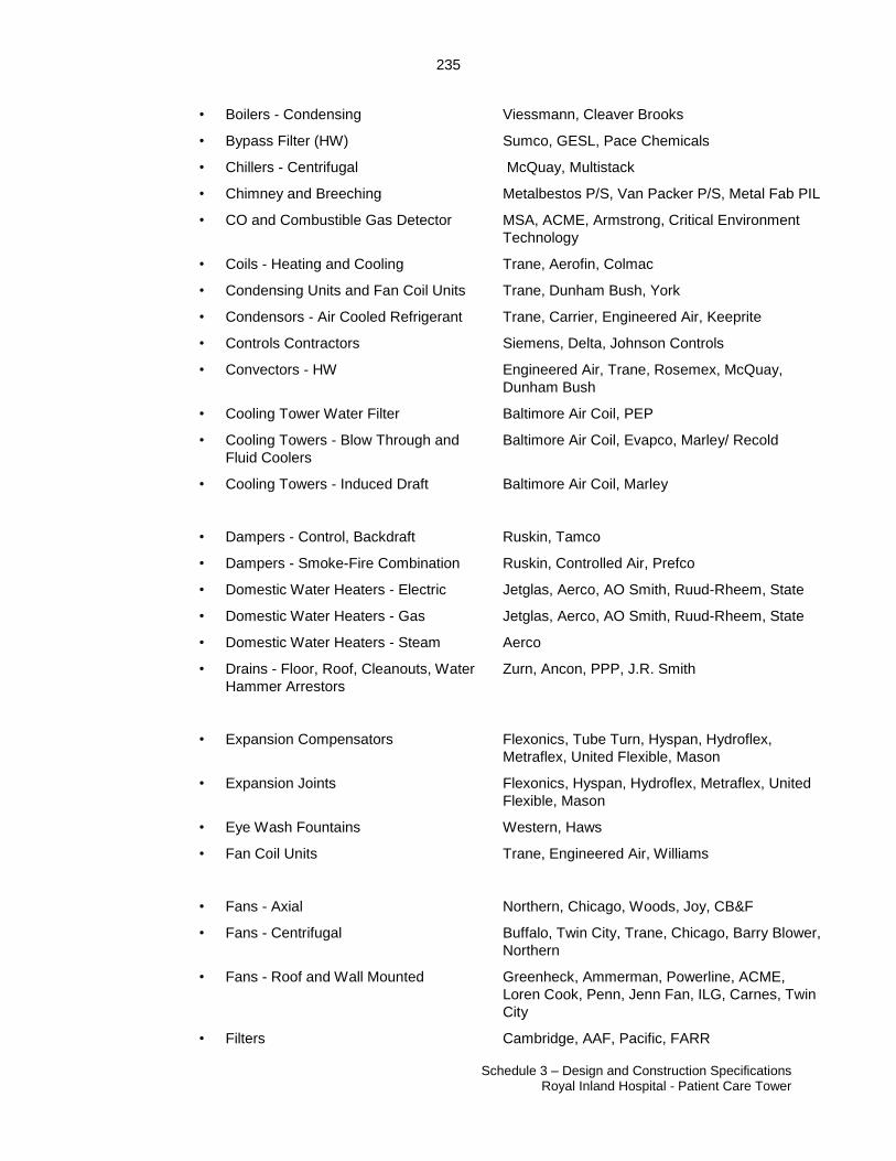
235
Schedule 3 – Design and Construction Specifications Royal Inland Hospital - Patient Care Tower
23507060.2
• Boilers - Condensing Viessmann, Cleaver Brooks
• Bypass Filter (HW) Sumco, GESL, Pace Chemicals
• Chillers - Centrifugal McQuay, Multistack
• Chimney and Breeching Metalbestos P/S, Van Packer P/S, Metal Fab PIL
• CO and Combustible Gas Detector MSA, ACME, Armstrong, Critical Environment
Technology
• Coils - Heating and Cooling Trane, Aerofin, Colmac
• Condensing Units and Fan Coil Units Trane, Dunham Bush, York
• Condensors - Air Cooled Refrigerant Trane, Carrier, Engineered Air, Keeprite
• Controls Contractors Siemens, Delta, Johnson Controls
• Convectors - HW Engineered Air, Trane, Rosemex, McQuay,
Dunham Bush
• Cooling Tower Water Filter Baltimore Air Coil, PEP
• Cooling Towers - Blow Through and
Fluid Coolers
Baltimore Air Coil, Evapco, Marley/ Recold
• Cooling Towers - Induced Draft Baltimore Air Coil, Marley
• Dampers - Control, Backdraft Ruskin, Tamco
• Dampers - Smoke-Fire Combination Ruskin, Controlled Air, Prefco
• Domestic Water Heaters - Electric Jetglas, Aerco, AO Smith, Ruud-Rheem, State
• Domestic Water Heaters - Gas Jetglas, Aerco, AO Smith, Ruud-Rheem, State
• Domestic Water Heaters - Steam Aerco
• Drains - Floor, Roof, Cleanouts, Water
Hammer Arrestors
Zurn, Ancon, PPP, J.R. Smith
• Expansion Compensators Flexonics, Tube Turn, Hyspan, Hydroflex,
Metraflex, United Flexible, Mason
• Expansion Joints Flexonics, Hyspan, Hydroflex, Metraflex, United
Flexible, Mason
• Eye Wash Fountains Western, Haws
• Fan Coil Units Trane, Engineered Air, Williams
• Fans - Axial Northern, Chicago, Woods, Joy, CB&F
• Fans - Centrifugal Buffalo, Twin City, Trane, Chicago, Barry Blower,
Northern
• Fans - Roof and Wall Mounted Greenheck, Ammerman, Powerline, ACME,
Loren Cook, Penn, Jenn Fan, ILG, Carnes, Twin
City
• Filters Cambridge, AAF, Pacific, FARR
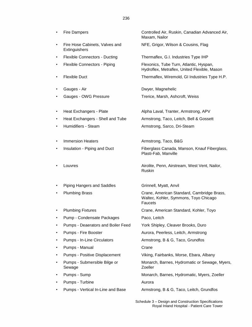
236
Schedule 3 – Design and Construction Specifications Royal Inland Hospital - Patient Care Tower
23507060.2
• Fire Dampers Controlled Air, Ruskin, Canadian Advanced Air,
Maxam, Nailor
• Fire Hose Cabinets, Valves and
Extinguishers
NFE, Grigor, Wilson & Cousins, Flag
• Flexible Connectors - Ducting Thermaflex, G.I. Industries Type IHP
• Flexible Connectors - Piping Flexonics, Tube Turn, Atlantic, Hyspan,
Hydroflex, Metraflex, United Flexible, Mason
• Flexible Duct Thermaflex, Wiremold, GI Industries Type H.P.
• Gauges - Air Dwyer, Magnehelic
• Gauges - OWG Pressure Trerice, Marsh, Ashcroft, Weiss
• Heat Exchangers - Plate Alpha Laval, Tranter, Armstrong, APV
• Heat Exchangers - Shell and Tube Armstrong, Taco, Leitch, Bell & Gossett
• Humidifiers - Steam Armstrong, Sarco, Dri-Steam
• Immersion Heaters Armstrong, Taco, B&G
• Insulation - Piping and Duct Fiberglass Canada, Manson, Knauf Fiberglass,
Plasti-Fab, Manville
• Louvres Airolite, Penn, Airstream, West Vent, Nailor,
Ruskin
• Piping Hangers and Saddles Grinnell, Myatt, Anvil
• Plumbing Brass Crane, American Standard, Cambridge Brass,
Waltec, Kohler, Symmons, Toyo Chicago
Faucets
• Plumbing Fixtures Crane, American Standard, Kohler, Toyo
• Pump - Condensate Packages Paco, Leitch
• Pumps - Deaerators and Boiler Feed York Shipley, Cleaver Brooks, Duro
• Pumps - Fire Booster Aurora, Peerless, Leitch, Armstrong
• Pumps - In-Line Circulators Armstrong, B & G, Taco, Grundfos
• Pumps - Manual Crane
• Pumps - Positive Displacement Viking, Fairbanks, Morse, Ebara, Albany
• Pumps - Submersible Bilge or
Sewage
Monarch, Barnes, Hydromatic or Sewage, Myers,
Zoeller
• Pumps - Sump Monarch, Barnes, Hydromatic, Myers, Zoeller
• Pumps - Turbine Aurora
• Pumps - Vertical In-Line and Base Armstrong, B & G, Taco, Leitch, Grundfos
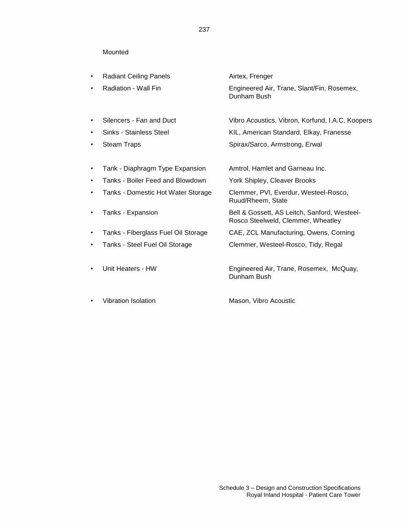
237
Schedule 3 – Design and Construction Specifications Royal Inland Hospital - Patient Care Tower
23507060.2
Mounted
• Radiant Ceiling Panels Airtex, Frenger
• Radiation - Wall Fin Engineered Air, Trane, Slant/Fin, Rosemex,
Dunham Bush
• Silencers - Fan and Duct Vibro Acoustics, Vibron, Korfund, I.A.C, Koopers
• Sinks - Stainless Steel KIL, American Standard, Elkay, Franesse
• Steam Traps Spirax/Sarco, Armstrong, Erwal
• Tank - Diaphragm Type Expansion Amtrol, Hamlet and Garneau Inc.
• Tanks - Boiler Feed and Blowdown York Shipley, Cleaver Brooks
• Tanks - Domestic Hot Water Storage Clemmer, PVI, Everdur, Westeel-Rosco,
Ruud/Rheem, State
• Tanks - Expansion Bell & Gossett, AS Leitch, Sanford, Westeel-
Rosco Steelweld, Clemmer, Wheatley
• Tanks - Fiberglass Fuel Oil Storage CAE, ZCL Manufacturing, Owens, Corning
• Tanks - Steel Fuel Oil Storage Clemmer, Westeel-Rosco, Tidy, Regal
• Unit Heaters - HW Engineered Air, Trane, Rosemex, McQuay,
Dunham Bush
• Vibration Isolation Mason, Vibro Acoustic
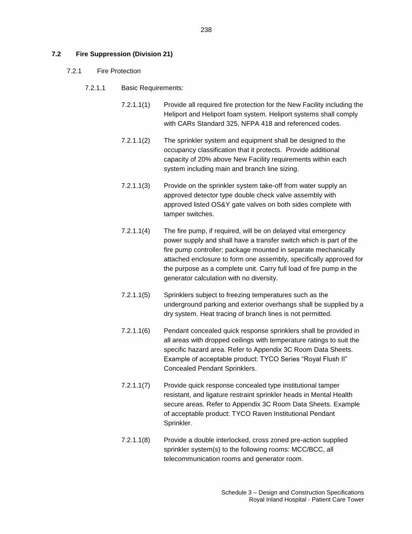
238
Schedule 3 – Design and Construction Specifications Royal Inland Hospital - Patient Care Tower
23507060.2
7.2 Fire Suppression (Division 21)
7.2.1 Fire Protection
7.2.1.1 Basic Requirements:
7.2.1.1(1) Provide all required fire protection for the New Facility including the
Heliport and Heliport foam system. Heliport systems shall comply
with CARs Standard 325, NFPA 418 and referenced codes.
7.2.1.1(2) The sprinkler system and equipment shall be designed to the
occupancy classification that it protects. Provide additional
capacity of 20% above New Facility requirements within each
system including main and branch line sizing.
7.2.1.1(3) Provide on the sprinkler system take-off from water supply an
approved detector type double check valve assembly with
approved listed OS&Y gate valves on both sides complete with
tamper switches.
7.2.1.1(4) The fire pump, if required, will be on delayed vital emergency
power supply and shall have a transfer switch which is part of the
fire pump controller; package mounted in separate mechanically
attached enclosure to form one assembly, specifically approved for
the purpose as a complete unit. Carry full load of fire pump in the
generator calculation with no diversity.
7.2.1.1(5) Sprinklers subject to freezing temperatures such as the
underground parking and exterior overhangs shall be supplied by a
dry system. Heat tracing of branch lines is not permitted.
7.2.1.1(6) Pendant concealed quick response sprinklers shall be provided in
all areas with dropped ceilings with temperature ratings to suit the
specific hazard area. Refer to Appendix 3C Room Data Sheets.
Example of acceptable product: TYCO Series “Royal Flush II”
Concealed Pendant Sprinklers.
7.2.1.1(7) Provide quick response concealed type institutional tamper
resistant, and ligature restraint sprinkler heads in Mental Health
secure areas. Refer to Appendix 3C Room Data Sheets. Example
of acceptable product: TYCO Raven Institutional Pendant
Sprinkler.
7.2.1.1(8) Provide a double interlocked, cross zoned pre-action supplied
sprinkler system(s) to the following rooms: MCC/BCC, all
telecommunication rooms and generator room.

239
Schedule 3 – Design and Construction Specifications Royal Inland Hospital - Patient Care Tower
23507060.2
7.2.1.1(9) Each fire extinguisher shall be located per relevant codes and to
the satisfaction of the Authority Having Jurisdiction and approved
for the hazard and classification of the space it serves.
7.2.1.1(10) All fire extinguishers in finished spaces shall be fully recessed.
Mental Health floors to have lockable cabinets without glass, keys
for cabinets to be provided to staff and FMO for access.
7.2.1.1(11) There shall be no wet sprinkler system in main Electrical Room (as
per BC Building Code). Provide either a double interlocked, cross
zoned pre-action supplied sprinkler for the main Electrical Room or
provide 3 hour rating around main Electrical Room and do not
install sprinklers in the room.
7.2.1.1(12) Project Co shall ensure Kamloops Fire Rescue is consulted and is
satisfied with the Heliport fire protection.
7.2.1.1(13) The contiguous building roof covering within 50 ft (15.2m) of the
landing pad edge shall have a Class A fire resistance rating for
exterior fire exposure pursuant to NFPA 418.
7.2.1.1(14) In the case of an aluminum Heliport deck, the Heliport shall be
designed with a foam Deck Integrated Fire Fighting System
(DIFFS) and a passive fire protection grid surface (passive fire
retarding surface).
7.2.1.1(15) The Heliport foam system shall cover the entire surface for ten (10)
minutes.
7.2.1.1(16) The Heliport foam system shall be a dry system that is freeze
protected.
7.2.1.1(17) Provide heat tracing of all mechanical piping and drainage gutters
that are not freeze protected.
7.2.1.1(18) Provide dedicated fire alarm pull stations in the Heliport vestibule
and at each roof egress location.
7.2.1.1(19) Provide foam shut off switches in the Heliport vestibule for Heliport
foam systems.
7.2.1.1(20) Provide portable fire extinguishers inside and outside the Heliport
vestibule, outside secondary TLOF egress and outside secondary
roof egress. Fire extinguishers shall meet the 10A-120B
specifications.
240
Schedule 3 – Design and Construction Specifications Royal Inland Hospital - Patient Care Tower
23507060.2
7.2.1.1(21) In addition to the requirements in this Schedule, provide any
standpipes, additional foam supply and appliances as required by
and for use of Kamloops Fire Rescue.
7.2.1.2 Performance Criteria:
7.2.1.2(1) All fire protection systems shall be hydraulically sized to NFPA
standards.
7.2.1.2(2) All equipment and installation shall be in accordance with
manufacturers’ requirements.
7.2.1.2(3) All equipment shall be ULC approved.
7.2.1.2(4) Qualified contractor licensed and regularly engaged in such
installations shall install all fire protection systems and equipment.
7.2.1.2(5) Provide backflow protection on all fire protection systems in
accordance with CSA requirements.
7.2.1.2(6) Locate zone shut-off valves so they are visible and accessible from
the floor. Do not conceal from view and do not locate in
Housekeeping rooms, storage rooms or stairwells. All valves
controlling water flow shall be monitored. On Mental Health floors
provide lockable heavy gauge cabinets with full metal door, heavy
duty security hinges, and mechanical deadbolt.
7.2.1.2(7) Fire Department connection shall be installed at a location
approved by the Authority Having Jurisdiction.
7.2.1.2(8) Install fire extinguishers located in a semi (unfinished areas) or
fully recessed (finished areas) cabinet to the satisfaction of the
Authority Having Jurisdiction.
7.3 Plumbing (Division 22)
7.3.1.1 Provide dedicated water, fire protection, natural gas, sanitary, medical gas, and
storm services as required and sized to suit the usage needs of the New Facility
and provide an additional future capacity of 20% above facility requirements on
day of occupancy based on Schedule 3 and Appendix 3A Clinical Specifications
and Functional Space requirements. Sewer, storm and water service
penetrations will be designed for flexibility and movement. No service is
permitted to be buried in concrete.
7.3.1.2 Provide two domestic water service connections each sized to provide 100% of
New Facility load including 20% spare capacity. Each supply into the Site shall
have a reduced pressure backflow preventer and 25 micron filtration. Each
supply shall have independent shut-off valves and wye trainer before the
241
Schedule 3 – Design and Construction Specifications Royal Inland Hospital - Patient Care Tower
23507060.2
backflow prevention. Provide a common water meter for the domestic service.
Submit the projected domestic water supply load and spare capacity values in
each design submission. Each connection point shall be from mains located on
different streets adjacent to the site. Connection points and service piping shall
be a minimum 50 m apart.
7.3.1.3 Basic Requirements
7.3.1.3(1) Domestic water systems shall meet the requirements outlined in
American Water Works Association (AWWA) standards. Provide
water treatment, as required to meet CSA/AWWA standards – and
IH Public Health water quality standard or the Canadian Drinking
Water standard. Provide an exterior domestic water connection to
enable domestic water connection to an exterior source if water
main service is not available from the City main. Provide Legionella
testing and certification prior to building Occupancy.
7.3.1.3(2) Refer to Section 5.3 regarding post disaster requirements for
services. Provide calculations confirming sanitary tank holding size
in DD and CD submissions and demonstrate system operation to
Authority prior to Occupancy.
7.3.1.3(3) Provide utilities-grade meters for domestic water, propane, and
natural gas. The meters will be used to accurately measure water
flow, propane and natural gas consumption in all flow conditions.
Refer to Appendix 8C Energy.
7.3.1.3(4) Provide the plumbing, fire protection, and medical gas systems in
such a manner as to avoid disruption to the operation of the New
Facility during maintenance or repairs. Design the systems so
that, as much as possible, Clinical Spaces do not need to be
entered when performing these functions. All isolation,
maintenance, balancing, and other service valves shall be located
in the corridor ceiling spaces and will be accessible from a 6’
ladder.
7.3.1.3(5) Distribute domestic water with a minimum of two risers to each
floor. Each riser shall be sized to provide full fixture load of floor.
Floor distribution shall utilize a completely looped system. The
distribution loop shall connect to all risers serving the floor. Divide
the total floor area into six equal zones and provide valves to allow
any one zone or riser to be shut off for service while maintaining
services to the other five zones.
7.3.1.3(6) Provide dedicated automated shut off valves on the water piping
serving each set of patient and secure room fixtures on Mental
Health and Mental Health Adaptive floors. The valves shall be
242
Schedule 3 – Design and Construction Specifications Royal Inland Hospital - Patient Care Tower
23507060.2
controlled remotely via the BMS. Staff on the Mental Health floor
shall be able to open and close the valves from the central Care
Team station. Staff on the Mental Health Adaptive floor will be able
to operate the valves from the observation alcoves using keyed
controllers.
7.3.1.3(7) Incorporate flexibility in the system designs to accommodate future
alterations. Label all systems clearly, including painting and
labelling of all pipes, ceiling identification dots, valve tagging, and
emergency valve identification signage.
7.3.1.3(8) Provide and install all fixtures and equipment in accordance with
manufacturer’s specifications, standards, and installation
instructions.
7.3.1.3(9) Provide the water systems to ensure that water is supplied at the
required pressures for optimal fixture operation to all water outlets.
Minimum water pressure will be maintained at 35 PSI to the most
remote fixture, to be demonstrated after commissioning.
7.3.1.3(10) Provide water inlet connections exterior to the New Facility for
supply water through tanker truck connections. Design to include
the ability to maintain the minimum pressure required by code in
the Building with building operational while drawing water from the
tanker truck by using a booster pump provided in the Building. The
system may use the domestic pumps utilized in daily operations to
achieve the required pressure, pumping system shall be on
delayed vital power. The system shall be designed in such a way
that it may be used as a backup should the municipal services fail
during a disaster such as an earthquake and shall tie in
downstream of the building back flow protection. The operation of
this system shall be demonstrated to the Authority in real time prior
to building occupancy.
7.3.1.3(11) Provide durable materials to allow for 24 hour a day operation with
minimal downtime. Domestic and non-potable water piping in the
Building shall be copper or ductile iron, stainless steel is allowed if
permitted by the Authority Having Jurisdiction. Pex piping is only
permitted for use in trap primer lines run in the slab. Sanitary and
storm piping above ground in the building shall be cast iron or
copper.
7.3.1.3(12) Domestic and non-potable water piping shall be connected by
soldering, brazing, threading, flange or roll grooved systems.
Connections utilizing compression shall not be used except for
connection of trap primer lines run in the slab.
243
Schedule 3 – Design and Construction Specifications Royal Inland Hospital - Patient Care Tower
23507060.2
7.3.1.3(13) Provide services for easy access and serviceability while avoiding
interference with other services during operation and maintenance
activities. All equipment, valves, and serviceable items shall be
accessible and removable without adapting wall/ceiling finishes or
structure. No plumbing piping (sanitary, storm, non-potable or
domestic water) shall pass through electrical, server,
communication, or UPS rooms.
7.3.1.3(14) Provide floor drains in all mechanical rooms, rooms noted in
Appendix 3C Room Data Sheets, and for all devices and
equipment requiring these drains including emergency showers,
reverse osmosis systems and backflow prevention devices.
Ensure all equipment drain piping is terminated at floor drains and
floors slope to the drains. Drains serving back flow prevention
devices shall be sized to accommodate the full flow of the back
flow preventer device as calculated by the device manufacture.
7.3.1.3(15) Connect the sanitary systems from the Laboratory Frozen Section
room by means of a single point connection per system to the main
sanitary building drain. Provide space and venting allowances for
future solids interceptors at this connection.
7.3.1.3(16) Provide dedicated storm piping from the Heliport to the aviation
fuel separator, no other piping shall tie in above interceptor.
Aviation fuel interceptor shall be sized to handle anticipated
helicopter’s fuel load in the case of a spill.
7.3.1.3(17) Provide, as required by Code, interceptors to intercept oil, grease,
dirt, solids, aviation fuel from Heliport, and bio-waste from the
facility. Interceptors shall be located in such a manner that they
can be emptied without running hoses through the Building.
7.3.1.3(18) Provide domestic water strainers at 25 microns on the incoming
services into the New Facility. Design shall provide a level of
redundancy which will allow for filter maintenance or replacement
to occur without affecting water flow to the New Facility.
7.3.1.3(19) Provide the domestic water booster pumping system per the
requirements of CSA Z317.1. The number and arrangement of
pumps shall be such that peak demand can be met in the event of
failure of one pump. Pumps shall be connected to delayed vital
power if required to provide minimum pressure requirements on
the top floor and included in the emergency generator calculations.
The system shall provide uninterrupted water service and constant
pressure under all conditions. It may also be able to work in
conjunction with section 5.3.1.3 requirements for post-disaster
conditions.
244
Schedule 3 – Design and Construction Specifications Royal Inland Hospital - Patient Care Tower
23507060.2
7.3.1.3(20) Provide all systems to meet the infection control requirements of
this Schedule and CSA Z317.13.
7.3.1.3(21) All piping shall be accessible. No in-slab or concrete encased
piping is allowed except piping serving the trap primers and
drainage piping serving elevator pit drains.
7.3.1.3(22) All Interventional Urology Operating Rooms and Secure Rooms
shall be equipped with flushing rim style floor drains. Flushing
device shall be concealed push button type, location of flush valve
button to be confirmed with user groups. Backflow prevention on
supply piping to floor drains shall be located in Housekeeping
and/or mechanical rooms. Provide concealed hose bib in Secure
Room Anterooms for Secure Room cleaning.
7.3.1.3(23) Provide floor drains beside all macerators for macerator overflow.
This floor drain shall not connect to the same horizontal branch
piping as the macerator drain.
7.3.1.3(24) Coordinate final location of all drains through User Group
Consultation Process.
7.3.1.3(25) All vents shall terminate outdoors; the use of Air Admittance
Valves in not permitted.
7.3.1.3(26) All piping shall be installed parallel to building lines. Vertical piping
shall be installed plumb and horizontal piping level or graded as
required by code for sanitary or storm systems. Provide support
under all wyes located at ends of branches and all p-traps.
7.3.1.3(27) The Heliport shall be supplied with fuel separators designed to be
of sufficient capacity and flow rate to include rain and fire
suppression water; and fuel containment tanks to hold 2,500 litres
of jet fuel. Reference the Heliport report by Ground Effect
Aerodrome Consulting Ltd. dated September 16, 2016.
Containment tanks shall be located in such a manner that they can
be emptied without running hoses through the building. Project Co
shall produce engineering verification documents for the fuel
separator and containment systems.
7.3.1.4 Performance Criteria
7.3.1.4(1) Connect all sanitary drainage utilizing gravity drainage whenever
possible. Provide underground overflow tank based on Section 5.3
Post-Disaster Requirements to hold sewage in the case of
municipal system failure. Provide a minimum storage capacity of 6
hours at peak load. Storage may consist of a single tank or
multiple interconnected tanks piped in a manner that allows for the
245
Schedule 3 – Design and Construction Specifications Royal Inland Hospital - Patient Care Tower
23507060.2
complete emptying of the tank or tanks from one emergency pump
out location. Sewage shall bypass tank in normal operation but be
directed into the holding tank if required via valves.
7.3.1.4(2) If pile foundations are used to support the structure, all underslab
piping shall be supported (hung) from the concrete slab above.
Hangers and rods shall be of sufficient strength and be installed at
intervals to carry the pipe and load and maintain the required
slope. Hangers and rods shall be corrosion resistant. Install light-
weight fill above all piping that is supported (hung) from the
concrete slab above. Support system shall be demonstrated to
work and demonstration witnessed by the Authority and
compliance team prior to installing on site.
7.3.1.4(3) Pumping systems for subsurface, storm, or sanitary drainage shall
include 100% redundancy (one redundant unit for each active unit)
and related equipment shall be supplied with Delay Vital power.
The storm / subsurface sump shall have twin compartments for
settling and pumping and shall be sized to prevent short cycling of
the pump. Provide local alarm and outputs to the BMS for high
water levels, status, and pump failure.
7.3.1.4(4) Insulate storm drainage, domestic and non-potable water piping,
cooling water, condensate and exposed p-traps in unheated areas
throughout per BCICA quality standards. Where piping and/or
piping components are subject to freezing, provide insulation and
heat tracing. Provide canvass or vinyl service jacket on all exposed
insulation inside, provide aluminum jacketing outside and on
exposed piping in underground parking. Ensure Life Safety
Systems are not installed in locations subject to freezing.
7.3.1.4(5) Provide drainage as required to alleviate water pressure exerted
onto the bottom of foundations and/or floor slabs. Perimeter
drainage and weeping tile shall be provided with cleanouts every
26 meters and for every change of direction greater than 45
degrees.
7.3.1.4(6) All plumbing drainage for acidic fluids shall be of ‘acid’ resistant
material to a point where dilution, as a result of additional
discharge from other sources or a neutralizer, reduces the acidity
of the discharge to a neutral pH.
7.3.1.4(7) Provide flushing and disinfection of domestic water systems to
AWWA and CSA infection control standards. Provide independent
testing of piping systems once flushing and cleaning has been
completed and provide documentation of testing to the Authority
for review.
246
Schedule 3 – Design and Construction Specifications Royal Inland Hospital - Patient Care Tower
23507060.2
7.3.1.4(8) Provide trap primers in drains that are subject to losing the trap
seal due to infrequent use, negative pressure, or overly hot
conditions. This includes floor drains in Mechanical, Housekeeping
or Soiled Utility rooms, floor drains for emergency showers, or floor
drains without a dedicated load for equipment or fixtures.
7.3.1.4(9) Provide electronic trap primers with solenoid valves controlled by
electronic time clock or BMS. Trap primers which rely on fixture
use or pressure drop shall not be used.
7.3.1.4(10) Conceal all sanitary, waste, and water piping in walls. Only trap
arms and water supply piping shall be exposed. Fixture outlet
piping for adjustable height fixtures shall be installed so that no
water can collect in the piping at any fixture height. Provide solid
supply tubing to sinks and lavatories for ease of cleaning, no
braided flex supplies permitted in Clinical Spaces.
7.3.1.4(11) If domestic water system pressure exceeds the acceptable delivery
pressure noted in BC Plumbing Code of 80 PSI, then provide
pressure reducing valves with 100% redundancy. Place the valves
in accessible locations in mechanical rooms or accessible chases.
Pressure reducing valves dedicated to equipment with specific
pressure requirements may be mounted beside equipment served
and do not require redundancy.
7.3.2 Plumbing Fixtures
7.3.2.1 Basic Requirements
7.3.2.1(1) All plumbing fixtures shall be suitable for a hospital facility.
Fixtures selected shall have proven acceptable hospital
performance from previous installations. All wall hung fixtures
shall be supported by floor mounted carriers and be equipped with
shrouds to cover traps and water shut offs. Shrouds shall be
completely sealed to prevent access by patients or public for
tampering or hiding of contraband. Provide fixture stops with lock
shield screwdriver slot.
7.3.2.1(2) Consult with the Authority on the selection of fixtures, and give
particular attention to performance relative to infection prevention
and control. The dimensions shall at a minimum meet CSA
Standards for all hand hygiene sinks. Small ‘bar’ type sinks (inside
dimensions less than 530 mm long by 400 mm wide) are not
acceptable. Public lavatories provided for handicap accessibility
and lavatories in patient washrooms shall meet Code accessible
guidelines. Provide a minimum distance of 800 mm from the wall
or fixture to centerline of the patient toilets.

247
Schedule 3 – Design and Construction Specifications Royal Inland Hospital - Patient Care Tower
23507060.2
7.3.2.1(3) Provide security and ligature restraint fixtures where noted and as
identified by Users. Refer to Appendix 3C Room Data Sheets for
locations requiring ligature resistant fixtures.
7.3.2.1(4) Toilets in bariatric washrooms shall be wall hung toilets as per
7.3.2.1(9) which will accommodate mobile commodes. Provide
mock up to confirm compatibility with the Authority supplied
equipment, i.e., commodes. Compatibility to be demonstrated and
accepted by the Authority through mock process as per Schedule
2 Section 5.5.
7.3.2.1(5) Provide anti-splash, anti-aerosolizing, faucet fittings (i.e. laminar
flow) that do not retain air. Unless otherwise specified, provide
gooseneck faucet fittings. Avoid low profile gooseneck faucet
fittings. Faucet discharge shall not discharge directly in drain grid.
7.3.2.1(6) With the exception of the Mental Health floors, fixtures shall not
have an overflow. Fixtures without overflow shall be provided with
strainer assemblies without overflow holes. Coordinate locations of
fixtures requiring overflow with Mental Health Users during design.
7.3.2.1(7) Public toilets, with the exception of the Mental Health floors and
handicap accessible toilets, shall consist of wall hung elongated
bowls with an open front seat and wired electronic flush valves.
Handicap accessible toilets shall be floor mounted rear outlet
bowls with an open front seat and wired electronic flush valves.
Wall hung toilets shall be a minimum height of 480 mm from floor
to rim, floor mounted toilets shall be a minimum of 425 mm from
floor to rim.
7.3.2.1(8) Staff toilets shall consist of wall hung elongated bowls with an
open front seat and wired electronic flush valves. All toilets shall
be a minimum height of 480 mm from floor to rim.
7.3.2.1(9) Patient toilets, with the exception of the Mental Health floors, shall
consist of wall hung elongated bowls, an open front seat, manual
high/low dual flow flush valves, be equipped with back rests and
have a minimum distance of 800 mm from the wall or fixture to
centerline of the toilet. All toilets will be a minimum height of 480
mm from floor to rim. Toilets shall be of a type that can be used
with portable bariatric commode chairs as required. Compatibility
to be demonstrated to the Authority prior to approval.
7.3.2.1(10) Patient and Public toilets for the Mental Health and Mental Health
Adaptive floors, shall consist of floor mount rear outlet elongated
bowls with white finish, an integral seat and manual concealed
push button operated flush valves. All toilets will be a minimum
248
Schedule 3 – Design and Construction Specifications Royal Inland Hospital - Patient Care Tower
23507060.2
height of 455 mm from floor to rim. Toilets shall be of a type that
can be used with portable bariatric commode chairs as required.
Compatibility to be demonstrated to the Authority prior to approval.
7.3.2.1(11) Patient water closets in Secure Rooms shall be 12 gauge 304
stainless steel combination water closet and lavatory fixtures with
white powder coating and integral recessed toilet paper holder.
Toilet shall be elongated bowl with integral contoured seat. Fixture
shall be able to withstand loadings of 5,000 pounds without
damage. Secure rooms shall be equipped with flushing rim floor
drains activated from the Anteroom. Anterooms shall be equipped
with hose bib in recessed box with lockable lid.
7.3.2.1(12) Water closets shall have a minimum MaP score of 800.
7.3.2.1(13) Showers and bath tubs shall be provided with pressure balanced
and high temperature limit valves, metal shower heads will be
utilized. Shower valves shall utilize single motion activation to
operate i.e. no pull out-turning motion only.
7.3.2.1(14) Bath tubs in Labour and Delivery room washrooms shall be
accessed from 3 sides. Minimum internal tub dimensions will be
1370 mm long by 700 mm wide and 500 mm deep. Telephone
shower from adjacent shower area shall be used for washing tub
occupant. Provide shower hose long enough to provide this
function.
7.3.2.1(15) Bath tubs shall be designed so the contents can be drained without
reaching into the tub. This shall be provided by mechanical or
other means.
7.3.2.1(16) Baby bathing sinks shall be integral counter top sinks with
manually operated goose neck faucet and spray hose complete
with vacuum breaker. Sink shall be minimum 250 mm deep by 500
mm long and 440 mm wide.
7.3.2.1(17) Patient showers shall be telephone style including ligature resistant
shower elbow with check valve and quick disconnect fitting.
Telephone shower hoses shall have smooth easy to clean surface.
Shower hoses to be sized to ensure the shower head cannot be
submerged in any adjacent plumbing fixture.
7.3.2.1(18) Slide bars provided for telephone showers shall be designed and
load rated to act as grab bars.
7.3.2.1(19) Shower bases shall ensure that the water is contained within the
shower area and drain fully without puddling. Shower bases shall
not be fiberglass or acrylic.
249
Schedule 3 – Design and Construction Specifications Royal Inland Hospital - Patient Care Tower
23507060.2
7.3.2.1(20) Showers for staff use shall not be less than 1200 mm x1200 mm.
7.3.2.1(21) Urinals shall be wall-hung and low-consumption with electronic
hands-free flush valve operation.
7.3.2.1(22) Public and patient washrooms (outside of IPU’s) lavatory fixtures
shall be made of an impervious, durable material and shall have
electronic hands-free type faucets with single temperature supply
that can be adjusted and set to the desired temperature.
Lavatories shall be wall hung and shall be wheelchair accessible.
7.3.2.1(23) Utility sinks shall be commercial grade stainless steel sinks integral
to the counter top. Faucets shall be goose neck laminar flow with
blade handle unless noted otherwise. Provide thermostatic mixing
valve to limit hot water discharge temperature to 43 degrees
Celsius.
7.3.2.1(24) Inpatient room washroom lavatory fixtures, with the exception of
Mental Health and Mental Health Adaptive floors, shall be made of
an impervious, durable material and shall have manually operated
faucets with blade handles. Provide thermostatic tempering valve
to limit hot water discharge temperature to 45 degrees C.
Lavatories shall be wall hung with shroud to cover waste and
supplies and shall be wheel chair accessible.
7.3.2.1(25) Inpatient room washroom lavatory fixtures on the Mental Health
and Adaptive floors shall be made of an impervious, durable solid
polymer fabricated surfacing material and shall have electronically
operated ligature resistant faucets. Provide thermostatic tempering
valve to limit hot water discharge temperature to 45 degrees C.
Lavatories shall be wall hung with shroud to cover waste and
supplies and shall be wheel chair accessible.
7.3.2.1(26) Inpatient room washroom fixtures for bariatric rooms shall comply
with Section 5.7 of this schedule.
7.3.2.1(27) Hand Hygiene sinks (Clinical hand wash) for Care Team Stations,
Clinical Spaces, examination rooms, and other similar function
rooms shall be CSA Z8000 compliant, wall hung, and shall be
made of an impervious durable material (vitreous china, porcelain).
Hand hygiene sinks in Soiled Utility, Housekeeping and other Back
of House areas may be made of stainless steel for impact
resistance. The sinks shall have electronic hands-free type faucets
with gooseneck spouts and single temperature supply that can be
adjusted and set to the desired temperature and shall have an
integral temperature control which is user adjustable. Hand
hygiene sink to be reviewed and approved by the Authority.
250
Schedule 3 – Design and Construction Specifications Royal Inland Hospital - Patient Care Tower
23507060.2
7.3.2.1(28) Nourishment station sinks shall be 2 compartment stainless steel
or solid polymer fabricated surfacing sinks integral to the
countertop with a blade handle goose neck faucet and an Instant
hot water dispenser. Provide water supply and drain connection for
ice maker.
7.3.2.1(29) Operating room scrub sinks shall equipped with be hands-free type
faucets. Faucets shall have sufficient clearance and height to
allow proper surgical scrubbing to occur. Faucet shall have a
single temperature supply with integral temperature control that
can be user adjusted. Number of compartments per scrub sink
shall depend on location/distribution and shall be confirmed with
Users during the User group meetings.
7.3.2.1(30) Provide dialysis boxes in three non-adjacent rooms on the
Med/Surgical and Mental Health Adaptive units located as
requested by users. Dialysis box shall be located on the same wall
as the patient bed head. Provide a dedicated cross connection
protected cold water system to supply the dialysis boxes. Drainage
piping from the boxes shall be acid resistant until the piping
connects with drainage piping with adequate flow to dilute the
waste. To maintain clear drainage provide a dedicated cross
connection controlled non potable water system with manually
adjustable pressure to flush the drain piping, system shall be
controlled by the BMS with adjustable time parameters.
7.3.2.1(31) Fixtures shall meet Code accessibility requirements.
7.3.2.1(32) Provide BMS controlled trap primers with automatic solenoid
valves to maintain the prime of p–traps for showers, lavatories, and
hand hygiene sinks in negatively pressurized Airborne Isolation
patient rooms and Anterooms.
7.3.2.1(33) Provide suitable quantities of mop sinks, hose bibbs, eye wash and
emergency shower stations to provide sufficient service to the New
Facility. Locate as noted in Appendix 3C Room Data Sheets and
as required by Users.
7.3.2.1(34) Provide all appropriate services and connections to all equipment
noted in Appendix 2E Equipment List, and as required for patient
care, laboratory and all other areas. Provide all components
including pressure reducing valves, water filters, and water
hammer arrestors to comply with the manufactures installation
requirements.
251
Schedule 3 – Design and Construction Specifications Royal Inland Hospital - Patient Care Tower
23507060.2
7.3.2.1(35) Sinks shall be stand-alone wall hung type or have bowls integrally
formed into countertops. Drop-in or under-mount style countertop
sinks shall not be used.
7.3.2.1(36) Provide impact resistant floor mop sink with stainless steel rim in
each housekeeping room of an adequate size, depth and access
to support the floor burnishers and other required housekeeping
equipment. Faucet shall have blade handles, integral stops,
vacuum breaker, and be equipped with a hose connection on the
spout. Mop sinks shall be concrete or terrazzo construction.
7.3.2.1(37) Provide a RPBD protected hose thread connection for all
housekeeping detergent dispensing systems, minimum one per
Housekeeping Room and as noted in Appendix 3C Room Data
Sheets.
7.3.2.1(38) Provide eye wash and emergency shower fixtures to comply with
ANSI 2358.1- 2009 or latest standards, Authority Work Place
Health and Safety Guidelines, and WorkSafe BC OHS Guidelines.
Project Co, in consultation with the Authority, to determine
emergency eye wash and shower requirements to suit the
identified level of risk.
7.3.2.1(39) Non-freeze hose bibs shall be provided around the Building on
each ground level exterior wall, on every exterior deck or enclosed
exterior area for patient or staff use, and on every level of the
underground parking. Underground parking systems shall be
isolated from the Building by a reduced pressure backflow device.
The design shall incorporate the ability to drain down the
underground parking systems during the winter so piping does not
require heat tracing.
7.3.2.2 Performance Criteria
7.3.2.2(1) Provide isolation valves for all plumbing services and clearly
identify the location of all valves.
7.3.2.2(2) Provide accessible clean-outs for all sinks and lavatories above the
flood-level rim of the sink. Also include provisions for clean outs on
rough-ins for future sinks and lavatories.
7.3.2.2(3) With the exception of the Mental Health and Mental Health
Adaptive patient water closets, provide Low/High flush toilets to
reduce water consumption.
7.3.2.2(4) Fixtures requiring backflow preventers shall have backflow
preventers concealed in wall or located in mechanical rooms or
Housekeeping Rooms.
252
Schedule 3 – Design and Construction Specifications Royal Inland Hospital - Patient Care Tower
23507060.2
7.3.2.2(5) Select toilets that shall reduce the spread of infection. Size flush
valves for the water consumption of the bowl. Toilet bowls shall
not splash or spray water onto the toilet rim or anywhere outside of
the toilet bowl and shall be designed to minimize the aerosolization
of the toilet contents.
7.3.2.2(6) All electronic sensor-activated fixtures shall be hardwired and on
delayed vital emergency power.
7.3.3 Domestic Hot Water Systems
7.3.3.1 Basic Requirements
7.3.3.1(1) Provide a domestic hot water system with sufficient capacity and
recovery rate for the hot water requirements of the New Facility.
Allow for 20% expansion capacity within each system for future
flexibility. Calculate domestic hot water demand in accordance with
ASPE Plumbing Engineering Design Handbook.
7.3.3.1(2) Domestic hot water supply will be of adequate temperature to
serve the needs of the New Facility and stored and circulated at
temperatures noted in CSA Z317.1 Table 1. Provide central mixing
valve to reduce from stored tank temperature to distribution
temperature. Provide thermostatic mixing valves where
temperatures are required to be less than 60ºCelsius at point of
use as required by CSA Standards. Provide fail safe bypass for
over temperature water after central mixing valve. Provide alarm to
BMS for over temperature conditions. To permit uninterrupted
service provide normally closed bypass around the mixing and
diverting valves complete with lockable valve. Bypass shall
connect to piping before over temperature monitoring sensor to
permit continuous monitoring of domestic hot water temperature.
7.3.3.1(3) Ensure timely delivery of hot water to all fixtures (0-10 seconds
acceptable).
7.3.3.1(4) Design the domestic hot water system to prevent growth and
spread of Legionella bacteria within the piping, fixtures, or any
other component. Design methods shall include eliminating dead-
leg piping and minimizing uncirculated piping by connecting the
circulation system as close as possible (less than 300mm) to
fixtures. Hand hygiene sinks and any electronically operated hands
free faucets shall have the circulation connection within 50mm of
the hot water supply to the fixture.
7.3.3.2 Performance Criteria
253
Schedule 3 – Design and Construction Specifications Royal Inland Hospital - Patient Care Tower
23507060.2
7.3.3.2(1) Provide the hot water generating equipment with 100%
redundancy. Include the fuel requirements for domestic hot water
generation in the 72 hour fuel allowance. If separate system is
provided for dedicated systems, this system shall also be included
in the fuel storage capacity.
7.3.3.2(2) Generate domestic hot water at 70ºCelsius to minimize conditions
for Legionella bacteria.
7.3.3.2(3) Recirculate domestic hot water from the distribution system(s)
back to the generating equipment.
7.3.3.2(4) Monitor hot water supply temperatures via the BMS with dedicated
sensors and provide alarm outputs when the temperature exceeds
or is lower than the design set point.
7.3.3.2(5) The domestic hot water generating equipment will meet the energy
efficiency requirements of ASHRAE 90.1.
7.3.3.2(6) Tanks used to store domestic hot water shall have internal active
heating elements (electric, gas, steam or hot water) capable of
attaining a water temperature in the tank of 80ºCelsius for the
purpose of sanitizing. All domestic hot water system components
shall be on delayed vital emergency power.
7.3.4 Medical Gas Systems
7.3.4.1 Basic Requirements
7.3.4.1(1) Project Co will provide oxygen to the New Facility by connecting to
the oxygen distribution piping at the bulk oxygen tank farm. Project
Co shall be responsible to run all piping to the tank farm from the
New Facility through the existing RIH Campus and shall coordinate
the connection point, routing, and tie in with the Authority and their
supplier. Provide flexible connection between New Facility and
existing RIH Campus.
7.3.4.1(2) Project Co will:
7.3.4.1(2)(a) provide centralized duplex bottle manifold supply
systems for the following medical gases: medical air
(4 hour reserve), oxygen (8 hour reserve), nitrogen,
nitrous oxide, and carbon dioxide based on
anticipated usage from the Appendix 3A Clinical
Specifications and Functional Space Requirements,
and user group meetings. Manifolds for nitrogen,
nitrous oxide, and carbon dioxide shall be sized to
hold a minimum of one week’s capacity with
254
Schedule 3 – Design and Construction Specifications Royal Inland Hospital - Patient Care Tower
23507060.2
additional 20% spare capacity in manifold sizing.
Manifold room shall have designated storage space
and racking for spare bottles equal to 72 hours
capacity for each system not connected to the
manifolds;
7.3.4.1(2)(b) design the centralized duplex bottle manifold supply
systems so that they shall, when required,
automatically switch to the spare bank of bottles
(and that switching to the spare bank is alarmed at
the master alarm); and
7.3.4.1(2)(c) include in the Building a separate enclosed room
with adequate space for the storage of medical gas
bottles for the following medical gases: argon,
helium, oxygen mix and rare gas/oxygen mix. Bottle
quantity shall be confirmed with Users. Minimum
room size of 9 NSM and complete with racks to
secure bottles.
7.3.4.1(3) Provide new central medical air and medical vacuum systems to
serve the New Facility and replace existing MR-4 medical air and
medical vacuum equipment with redundancy so that if 2 of the
compressors or pumps in either system were to fail or be shut
down, there shall be no degradation of the system’s ability to meet
the capacity requirements of the New Facility and RIH Campus
systems.
7.3.4.1(4) Connect new central medical air and medical vacuum systems to
vital or delayed vital emergency power with full anticipated load
carried in emergency generator calculation without diversity.
Provide valve and capped air intake connection in mechanical
room to permit medical air system to draw air from supply air
ductwork in the case of forest fire or high pollution condition.
7.3.4.1(5) Provide nitrogen at 160 psi supply pressure to control panels in
OR’s to accommodate specialty tools currently used at RIH.
7.3.4.1(6) Provide instrument air with N+1 redundancy for non-medical
compressed air consuming equipment. Connect to delayed vital
emergency power. Outlet pressure shall be user adjustable.
7.3.4.1(7) Provide active Anesthetic Gas Scavenging System with
redundancy so that with 2 vacuum producers out of service the
system can meet design loads. System shall have 40% spare
capacity to permit extension of system to existing OR’s in future.
System shall operate at 12”Hg. Provide valve and capped
255
Schedule 3 – Design and Construction Specifications Royal Inland Hospital - Patient Care Tower
23507060.2
connections to permit connection of anesthetic gas reclamation
system in future.
7.3.4.1(8) Project Co shall install an emergency oxygen outlet suitable for a
tanker truck to draw alongside and dispense oxygen into the New
Facility system. Provide manually operated valves to isolate the
New Facility from the rest of the RIH Campus where oxygen line
enters the New Facility. If piping between the bulk oxygen tank
farm and the New Facility is damaged these valves will be closed
to permit the pressurizing of the New Facility system by the tanker
truck.
7.3.4.1(9) With the exception of outlets such as those located in booms and
single outlets, locate medical gas outlets in either a built-up
headwall or prefabricated headwall system that incorporates
medical gases, electrical and data outlets as per Appendix 3C
Room Data Sheets;
7.3.4.1(10) All pipe and pipe fittings will be in accordance to ASTM 88, de-
greased copper Type ‘L’.
7.3.4.1(11) Service Outlets
7.3.4.1(11)(a) Provide recessed service outlet boxes designed for
concealed piping and fabricated for straight insertion
of secondary equipment.
7.3.4.1(11)(b) Each recessed wall outlet shall have a permanently
marked, colour-coded non-interchangeable index
system to prevent connection to the wrong gases.
Provide a secondary check valve to maintain the line
pressure if the primary valve is removed for
maintenance.
7.3.4.1(11)(c) Provide 2-part DISS type outlet connections for each
medical gas. Refer to Appendix 3C Room Data
Sheets for locations and quantities.
7.3.4.1(11)(d) Secure Outlets – provide a secure tamper-proof
headwall system including recessed outlets which
will be concealed. Refer to 6.11.3 Headwalls.
7.3.4.1(12) Ball type shut off valves shall be ULC labelled showing the
appropriate gas service & pressure rating. Valves shall swing out
during installation and have a quarter turn from full open to close.
All valves to be dual port. In the case of valves over 2” for vacuum
system butterfly valves may be used instead of ball valves
256
Schedule 3 – Design and Construction Specifications Royal Inland Hospital - Patient Care Tower
23507060.2
provided purge points are provided in piping immediately before
and after valve and the valves are stainless.
7.3.4.1(13) Area zone shut off valves shall be housed in a single box
comprised of multiple shut off valves with tube extensions, lexan
glass door with hinges and pull out opening ring. Provide pressure
/ vacuum gauges for each service. Provide label stating rooms
served by valves.
7.3.4.2 Performance Criteria
7.3.4.2(1) Provide the medical gas system so that there is a minimum of one
zone shut off valve per program area and a local alarm panel for
each zone. Monitor all local alarms on BMS system.
7.3.4.2(2) Provide valve and capped medical gas piping connection stubbed
into the ceiling of the MH&SU Psychiatric Inpatient Unit and the
MH&SU Child and Adolescent Mental Health Crisis Intervention
Program for medical air, vacuum, and oxygen for future flexibility.
Piping to be same size as provided to the Medical Mental Health
Adaptive Inpatient Unit. Provide oxygen, medical air, medical
vacuum and AGSS piping stubbed into the ceiling space of Level 4
North for new PARR to be completed in Phase 2. Size oxygen,
medical air and medical vacuum based on the information in
Appendix 3C Room Data Sheets and size the AGSS to serve the
OR spaces on Level 4. Provide piping to connect the New Facility
medical vacuum and medical air systems to the existing RIH
Campus medical air and medical vacuum systems routed through
the Level 4 North ceiling. Provide flexible connections at seismic
joints and isolation valves as permitted by Z7396.1 so the New
Facility can be isolated from the existing RIH Campus in a
catastrophic event. Tie into existing valved stubs on the 8th floor
North Tower (MR- 4). Include the anticipated loads of above noted
areas in the source equipment sizing before the 20% spare
capacity calculation.
7.3.4.2(3) All medical gas piping in normally inaccessible areas (e.g. behind
walls and boarded ceilings) will be clearly identified.
7.3.4.2(4) Provide the medical gas system such that each program area shall
have its own valve box and alarm panels. Alarm panels shall be
connected to delayed vital emergency power.
7.3.4.2(5) Provide an alarm interface signal to the BMS for critical alarms
such as low or high pressure from each local alarm station.
7.3.4.2(6) All piping, valves and filters shall be factory cleaned and capped or
sealed to prevent contamination.
257
Schedule 3 – Design and Construction Specifications Royal Inland Hospital - Patient Care Tower
23507060.2
7.3.4.2(7) All departments shall be provided with local valve boxes and alarm
panels.
7.3.4.2(8) Provide a master medical gas alarm panel to monitor all medical
gas functions. Master alarm panel shall be located in location with
24 hour continuous responsible surveillance. The Authority has
selected the Switchboard Room F.13 as a suitable location for
these alarm panels. Project Co shall relocate the existing medical
gas master alarm points from the existing facility and provide a
new master alarm panel for these existing alarms in the
Switchboard Room or other suitable room agreed upon with the
Authority during the design process. Remote alarm annunciation
shall be provided at a location with 24 hour continuous monitoring
by FM provider/personnel and not be located in Clinical Spaces.
Provide an inter-connected status and alarm point and signal to the
BMS. The FM provider shall be the first responder.
7.3.4.2(9) Individually connect all alarms from master alarm panels to the
BMS.
7.3.4.2(10) All medical gas systems shall be certified in accordance with CSA
standards by an independent and qualified testing agency who
shall be employed by the Authority.
7.3.4.2(11) All systems components requiring electrical power shall be on
delayed vital emergency power.
7.3.4.2(12) The medical gas supply system will be for patient consumption
only. If equipment and/or procedure(s) require medical grade gas
supply, then provide separate dedicated source equipment, piping,
valves and monitoring to accommodate that application.
7.3.4.2(13) If existing bottle manifold is to be reused, connect existing RIH
Campus medical air bottle reserve to new Master Alarm panel
location. Project Co shall upgrade existing medical air bottle
reserve duplex manifold controller as required to meet current CSA
Standards and to ensure compatibility with Master Alarm panel.
7.3.4.2(14) Project Co shall remove all redundant MR-4 medical air and
medical vacuum source piping, equipment and control components
from the existing campus once the New Facility medical air and
medical vacuum systems have been commissioned and connected
to the existing campus systems and the existing equipment is no
longer required.
7.3.5 Specialty Systems
7.3.5.1 Provide all specialty systems required for the operation of the Building, including:
258
Schedule 3 – Design and Construction Specifications Royal Inland Hospital - Patient Care Tower
23507060.2
7.3.5.1(1) acid waste piping and venting; and neutralization
7.3.5.1(2) oil, grease, dirt, aviation fuel, and solids interceptors
7.3.5.1(3) reverse osmosis water systems
7.3.5.1(4) medical gas systems
7.3.5.1(5) bio-waste systems
7.3.5.2 Interceptors shall be provided and installed in accordance with manufacturer’s
specifications and applicable codes. Interceptors shall be located so they can be
serviced without pulling hoses through the New Facility or releasing
contaminates into the surrounding air.
7.3.5.3 Acid waste, vent piping, and fittings shall be suitable for the pH levels of the
waste system.
7.3.5.4 Oil storage and distribution systems
7.3.5.4(1) Provide a complete and fully operational fuel oil system to serve
the new emergency power generation systems. Provide a total of
72 hours of fuel storage in an underground and day tank per
system or dedicated belly tank system. Dedicated belly tanks on
generators not connected to a central storage tank shall each be
sized to provide 72 hours of fuel to generator served. Project Co
to maintain fuel supply infrastructure serving the existing
generators until new generators are operational, connected to the
existing power distribution, and accepted by the Authority.
7.3.5.4(2) Storage tanks shall be double wall tanks complete with mechanical
anti-overfill device, inventory floats for fuel and water levels,
interstitial and turbine leak detection, personnel-access for tank
maintenance and spill containment on fill connection from tanker
truck.
7.3.5.4(3) Underground double wall piping system will include leak detection
monitored transition sumps. Piping shall rise above grade before
entering the Building. Provide shut off valves before and after the
piping enters the Building above grade. Provide signage marking
location of exterior valves for First Responders.
7.3.5.4(4) Provide an inventory system to provide fuel levels to transfer
pumps, monitor inventory and water levels in all tanks, and all
interstitial / turbine / and transition sump leak detectors. Inventory
system will communicate with BMS to provide alarms / status, tank
inventory levels and graphics.

259
Schedule 3 – Design and Construction Specifications Royal Inland Hospital - Patient Care Tower
23507060.2
7.3.5.4(5) Provide duplex transfer pumps with control panel, relief valves,
strainers, check valves, gauges, flow switches and hand priming
ability for remotely located suction pumps. Control panel shall
communicate and receive signals from BMS and inventory
systems. Transfer pumps shall shut down on low level alarm from
underground storage tanks.
7.3.5.4(6) Provide fuel filtering and polishing to maintain stored fuel at the
recommended generator supplier fuel quality parameters. Provide
redundancy and bypasses required to allow filter maintenance
without interrupting fuel flow to generators.
7.3.5.4(7) Provide cathodic corrosion protection on any direct buried steel
pipe associated with oil distribution and storage system.
7.3.5.4(8) Remove all redundant equipment, piping, controls, tanks, etc. from
the existing emergency power generation systems being relocated.
7.3.5.5 Propane and Natural Gas Systems
7.3.5.5(1) Provide new propane system to supply back up fuel to the gas
fired devices in the New Facility.
7.3.5.5(2) Connect new system to the existing 25,550 gallon liquid propane
tank. Provide new vaporizer and calorific convertor sized for full
existing RIH Campus load plus the New Facility load and connect
the new vaporizer and calorific convertor to the existing liquid
propane tank and to the existing 100 mm supply to the RIH
Campus and to the new supply pipe to the New Facility. New
vaporizer and calorific convertor shall be installed parallel with
existing vaporizer convertor system to permit existing system to
provide redundancy. Run the new supply piping from the propane
tank location and connect to the gas line serving the New Facility
after the gas meter. Provide 3 way isolation valve on the
propane/natural gas connection.
7.3.5.5(3) Propane vaporizer and calorific convertor shall be connected to
delayed vital or vital power with full load accounted for in the
emergency generator calculation. This system to be monitored for
status and alarms by the BMS.
7.3.5.5(4) The existing natural gas meter station and propane interconnection
are located in the foot print of the New Facility. Project Co is
responsible for relocation of the natural gas meter station, existing
propane gas connection and reconnection of the existing gas
infrastructure to new service location. Please refer to Appendix 3G
Site Services for new gas line routing, meter and propane
interconnection locations. Refer to Appendix 3I Natural Gas
260
Schedule 3 – Design and Construction Specifications Royal Inland Hospital - Patient Care Tower
23507060.2
Routing for schematic level gas line routing through the existing
facility to connect mechanical rooms to relocated gas service.
Routing to connect kitchen appliances will also be the
responsibility of Project Co. Drawings for gas routing shall be
submitted with the SD, DD, CD drawing submissions as per
Schedule 2 Design and Construction Protocols and Appendix 2C
Review Procedure for Authority review and approval of routing.
7.3.5.5(5) Project Co to provide temporary connections and work arounds to
accomplish the relocation and reconnection of natural gas to the
existing facility without disrupting gas flow for longer than 4 hours
at time agreed to by the Authority.
7.3.5.5(6) Project Co shall provide a meter and propane interconnection with
minimal visual impact by recessing or fully screening new
assembly.
7.4 Heating, Ventilating and Air Conditioning (Division 23)
7.4.1 Building Heat Source
7.4.1.1 Project Co will provide heating for the New Facility and connected RIH Campus
systems as noted in 7.4.1.1(1) by providing a stand-alone heat source in the New
Facility.
7.4.1.1(1) Project Co shall provide multiple hot water heating boilers to
provide all necessary heating including redundancy and additional
20% allowance for future flexibility above New Facility requirement
including existing MDR and renovated Level 4 North PARR
spaces, domestic hot water generation, if applicable, and to
replace the existing RIH Campus boiler systems located in the
North Tower 8th floor (MR-4), West Wing Level 5 (MR-18), West
Wing Level 2 (MR-9), and East Wing (MR-10) to meet the
standards as follows:
7.4.1.1(1)(a) the boilers will provide heat for the entire connected
facility systems to meet their full functional
requirements for a period of at least 72 hours
following any disruption of the supply of natural gas
utility service.
7.4.1.1(2) Project Co to utilize existing propane storage as noted in Section
7.3.5.
7.4.1.1(3) Project Co shall provide clean steam for humidification. Steam will
be generated at point of use by electricity or gas. Clean steam for
humidification shall not contain chemicals or contaminates harmful
to health or which slow the healing process. Piping used for clean
261
Schedule 3 – Design and Construction Specifications Royal Inland Hospital - Patient Care Tower
23507060.2
steam shall not contaminate the steam it carries. R.O. water to be
used for creating the feed water for humidification steam.
7.4.1.1(4) Project Co shall not use the existing RIH plant to provide back-up
heating or humidification for the Building.
7.4.1.1(5) The heating plant shall consist of multiple individual boilers. The
heating plant shall be sized so that with the largest boiler out of
service the plant can provide 100% of the design load under
normal operating conditions as defined by CSA Z317.2, including
the 20% spare capacity and the domestic hot water generation
load if it is connected to and dependent on the heating plant.
Heating plant shall be capable of meeting the full heating load
under catastrophic 100% outdoor air conditions with plant fully
operational and have sufficient capacity to continue essential
operations as defined in CSA Z317.2 with the largest boiler out of
service in catastrophic mode. January design temperatures are as
follows; 2.5%: -25ºC, 1%: -28º.
7.4.1.1(6) New PCT boiler plant to also include 12 MMBtu/hr capacity to meet
the heating load with redundancy currently provided by the
decentralized boiler systems located in the North Tower Level 8
(MR-4), West Wing Level 5 (MR-18),West Wing Level 2 (MR-9)
and East Wing (MR-10).
7.4.2 Heating
7.4.2.1 Basic Requirements
7.4.2.1(1) Sources and related accessories of ventilation and/or heating
systems that serve the Building shall be connected to the delayed
vital power supply and accounted for in the emergency generator
calculation without diversity.
7.4.2.1(2) It is essential that perimeter heating with radiant ceiling panels be
utilized for the entire Building, excluding mechanical, electrical and
communication rooms. Radiant panels shall also be provided
around all sides of light wells and skylights. If the LDR ensuite
washroom is located with an exterior wall, provide separate control
zone for the radiant panel to permit temperature control of the
washroom.
7.4.2.1(3) Boilers shall be capable of operating at a minimum AFUE
efficiency of 93% at all firing rates. Consideration will be given to
designing and providing a heating system with condensing boilers.
Steam generators shall operate at a minimum efficiency of 80%.
262
Schedule 3 – Design and Construction Specifications Royal Inland Hospital - Patient Care Tower
23507060.2
7.4.2.1(4) Boilers shall operate on natural gas as the primary fuel and
blended propane to match natural gases calorific value as the
secondary fuel. Adequate storage of secondary fuel will be
provided on-site to operate the boilers for a minimum of 72 hours,
under maximum demand conditions. Complete boiler plant shall
be designed such that low load and shoulder season loads can be
achieved at high efficiency and that the total capacity will
accommodate an additional 20% allowance for future above
facility requirements.
7.4.2.1(5) Provide dedicated freeze-proof heating systems to serve the
Heliport TLOF, Heliport exterior access walkway path, Heliport
TLOF secondary egress stairs and all exterior vehicle ramps or
drive aisles with slopes of 6% or greater. Provide 100%
redundancy in source components.
7.4.2.1(6) Provide adequate expansion compensation for heating piping.
Location of anchors and guides, design of expansion
compensation loops and selection of expansion compensation
devices shall be based on a thorough review of piping layout and
piping stress analysis. Anchor systems to be pour-in-place type
(inbed or pre-set).
7.4.2.1(7) All high points in piping shall be equipped with automatic air
removal devices including air collection chambers and air vents.
Relief will be piped to nearest drain, glycol systems pipe to
receiver or back to feed tank. Discharge termination shall be
visible.
7.4.2.1(8) Provide the HVAC systems to avoid disruption to the operation of
the Building during maintenance or repairs. Design the systems so
that, as much as possible, the Clinical Spaces do not need to be
entered when performing these functions. All isolation,
maintenance, balancing, and other service valves will be located in
the corridor ceiling spaces and will be accessible from a 6’ ladder.
7.4.2.1(9) Equipment and piping shall be installed with adequate service
space, access panels and the ability to remove equipment for
servicing or replacement without adapting wall/ceiling finishes or
structure.
7.4.2.1(10) Isolation valves, unions and bypass piping shall be provided to
allow for equipment isolation and removal without unduly affecting
the system operation or major drain down.
263
Schedule 3 – Design and Construction Specifications Royal Inland Hospital - Patient Care Tower
23507060.2
7.4.2.1(11) Balancing valves, flow-measuring devices, temperature and
pressure sensors shall be provided throughout the system to
facilitate system balancing.
7.4.2.1(12) Design pumps to operate at the system fluid temperature without
vapour binding and cavitation. Pumps shall be non-overloading in
parallel or individual operation and will operate within 25% of the
midpoint of published maximum efficiency curve. Where there is
more than 40% variation in flow, variable frequency drives will be
provided. Provide grounding rings on all motors equipped with
VFD’s.
7.4.2.1(13) Pump construction and installation shall permit complete pump
servicing without disrupting piping or motor connections.
7.4.2.1(14) Locate services that require access for regular maintenance above
non-critical spaces such as corridors to minimize or eliminate
disruptions to the delivery of health care services.
7.4.2.1(15) Insulate all heating water piping, equipment and accessories in
accordance with the most stringent of all applicable standards
including applicable BCICA and ASHRAE standards. Provide a
canvas or PVC service jacket on all exposed piping inside. Exterior
piping shall have aluminum jacketing. Piping 3 meters above
finished floor in mechanical rooms does not require service
jacketing.
7.4.2.1(16) Heating water piping, with the exception of buried snow melt
systems, shall be Schedule 40 steel or Type L copper. Utilize
screw fittings for steel piping 50 mm and smaller and welded
fittings for steel piping 65 mm and larger. Copper piping for run
outs, coil connections and radiant panel circuiting shall be soldered
with lead free or 95/5 solder.
7.4.2.1(17) Design seismic mitigation and building separation devices for all
piping that crosses buildings and/or utility corridors.
7.4.2.1(18) With the exception of snow melt systems, no piping shall be buried
in concrete. All piping shall be able to be accessed without
removing or disrupting structural members or components.
7.4.2.1(19) Provide heating supply and return piping stubbed into the ceiling of
Level 4 North for the PARR renovation. Piping shall be sized to
handle the designed heating loads for the PARR renovation. Piping
shall be provided with valves and capped for future connection
without impacting the operation of the New Facility.
264
Schedule 3 – Design and Construction Specifications Royal Inland Hospital - Patient Care Tower
23507060.2
7.4.2.1(20) Provide heating supply and return piping to connect the New
Facility boiler plant with the existing RIH Campus systems located
in mechanical rooms on North Tower Level 8(MR-4), West Wing
Level 5 (MR-18), West Wing Level 2 (MR-9), and East Wing (MR-
10). Piping shall be sized in accordance with Schedule 3
requirement for 20% spare capacity. Provide all additional
equipment including but not limited to pumps, heat exchangers,
energy meters, control components, and chemical treatment
equipment as required to provide a complete and working heating
system serving all connected systems.
7.4.2.1(21) Project Co shall replace the existing Alumnae Tower boiler utilizing
an unused boiler shell from the RIH Campus. Project Co is
responsible for all labour, parts, and factory start-up costs to
replace the existing Alumnae boiler and create a working factory
certified boiler to serve Alumnae Tower. Project Co is responsible
for the removal of the redundant boiler shell.
7.4.2.1(22) Project Co shall decommission and remove all redundant boilers
and associated boiler breeching from the existing RIH mechanical
rooms located in the North Tower on Level 8 (MR-4), West Wing
Level 5 (MR-18), West Wing Level 2 (MR-9) and East Wing (MR-
10) once the New Facility boiler plant has been connected and
commissioned. Project Co shall make good all openings through
the existing building envelopes which currently accommodate
hydronic boiler breeching.
7.4.3 Air Conditioning
7.4.3.1 Basic Requirements
7.4.3.1(1) Provide all necessary space, ventilation and process cooling for
the Building including an additional 20% spare capacity for future
use above New Facility requirements including existing MDR
requirements and renovated Level 4 North PARR loads. Design
shall accommodate the removal of heat generated by equipment;
refer to Appendix 2E Equipment List for list of equipment. Connect
all cooling systems to delayed vital and account for full operational
load in emergency generator calculations without diversity.
7.4.3.1(2) The design and installation shall comply with all applicable
standards including CSA B52, Mechanical Refrigeration Code.
7.4.3.1(3) Equipment shall be CSA approved and shall meet all applicable
standards including applicable sections of the ASME Code.
265
Schedule 3 – Design and Construction Specifications Royal Inland Hospital - Patient Care Tower
23507060.2
7.4.3.1(4) Welding materials, fabrication standards and labour qualifications
shall comply with all applicable standards including applicable
ANSI and ASTM Codes.
7.4.3.1(5) Cooling tower performance will be certified in accordance with CTI
(Cooling Tower Institute) Standard STD-201. No open type
cooling towers are allowed; condensing water from the chillers
shall be in a closed loop. Evaporative cooling of the chilled water
closed loop bundle is acceptable. Cooling towers shall be visibly
screened for full height of equipment sympathetic to Architectural
Design. They shall not be visible from windows in New Facility.
7.4.3.1(6) Chillers and cooling towers shall be designed and located so as
not to have an adverse effect on the RIH Campus mechanical
systems or the Heliport’s landing pattern. Installation shall be fully
screened.
7.4.3.1(7) Install chillers and cooling towers for ease of operation,
accessibility for maintenance and safety and appearance.
7.4.3.1(8) Installation shall comply with ASHRAE Guideline 12-2000 for
Minimizing the Risk of Legionellosis Associated with Building
Water Systems.
7.4.3.1(9) Provide sufficient redundancy so that with the largest chiller and
cooling tower out of service, the system can provide 100% cooling
required to all spaces classified as Type 1 by CSA Z317.2 Table 1
or as noted as Type 1 in Appendix 3C Room Data Sheets and 50%
of the cooling requirements of all other spaces connected.
7.4.3.2 Performance Criteria
7.4.3.2(1) Provide dedicated and continuously available chilled water
systems for all New Facility areas containing specialized medical
equipment, walk in coolers, elevator rooms, server rooms,
communication and IMIT rooms and electrical rooms where heat
rejection to outdoors is not possible for managing continuous
internal heat gains. This system may be supplied from the New
Facility chiller plant provided that redundancy requirements noted
in 7.4.3.1(9) and the dedicated system requirements combined,
are provided and the New Facility chiller plant is designed to run
year round. Cooling distribution systems shall be designed such
that non critical loads can be isolated and cooling directed toward
critical areas if the system capacity is limited due to equipment
failure. All cooling systems shall be on delayed vital. Specialized
equipment requiring cooling will be confirmed during user group
meetings.
266
Schedule 3 – Design and Construction Specifications Royal Inland Hospital - Patient Care Tower
23507060.2
7.4.3.2(2) Provide water cooled refrigeration systems where required for the
medical needs connected to the dedicated condensing water
system.
7.4.3.2(3) Provide sufficient space cooling capacity to meet the required
indoor design temperatures outlined in applicable CSA Standards
while using 39 degrees Celsius dry bulb and the July 2.5% outside
design wet bulb temperature outlined in the BC Building Code or
1% Design Cooling Temperature as per ASHRAE, whichever is
greater.
7.4.3.2(4) The HVAC system shall be designed to be able to utilize 100%
outdoor air for free cooling as a means of space cooling.
7.4.3.2(5) Ensure that no air within the air conditioning system, outside of the
central air handling equipment, drops below its dew point
temperature.
7.4.3.2(6) CFC and HCFC based refrigerants shall not be used in the
refrigeration equipment.
7.4.3.2(7) Design piping to be installed in an orderly manner (aligned with
structural elements and at right angles). Slope piping and provide
low point drains to permit complete drainage of the system.
7.4.3.2(8) All high points in the closed loop piping shall be equipped with
automatic air removal devices such as air collection chambers and
air vents. Relief shall be piped to drain. Glycol systems will be
piped back to make up tank.
7.4.3.2(9) Provide equipment and piping with adequate service space,
access panels and ability to remove equipment from the New
Facility for servicing or replacement without affecting facility
operations. Provide chilled water, pumps, risers and piping with
20% spare capacity to accommodate future flexibility.
7.4.3.2(10) Provide isolation valves, unions and bypass piping to allow for
equipment isolation and removal without unduly affecting the
system operation or major drain down.
7.4.3.2(11) Select pumps that operate without vapour binding or cavitation, be
non-overloading in parallel or individual operation, and operate
within 25% of the mid-point of published maximum efficiency
curve.
7.4.3.2(12) Pump construction and installation shall permit complete pump
servicing without breaking piping or motor connections.
267
Schedule 3 – Design and Construction Specifications Royal Inland Hospital - Patient Care Tower
23507060.2
7.4.3.2(13) Locate services that require access for regular maintenance above
non-critical spaces so that there is minimal to no disruption to the
delivery of health care services.
7.4.3.2(14) Insulate all chilled water piping, equipment and accessories in
accordance with the most stringent of applicable standards,
including BCICA and ASHRAE standards. Provide a canvas or
PVC service jacket on all exposed piping inside; exterior piping
shall have aluminum jacketing. Piping 3 m above finished floor in
mechanical rooms does not require service jacketing.
7.4.3.2(15) Provide 100% redundancy for fan coil units or other source
equipment serving electrical and communication rooms to ensure
continuous cooling in the case of a unit failure or required
maintenance shut down.
7.4.3.2(16) Chilled water and condenser water piping shall be Schedule 40
Steel or Type L copper. Utilize screw fittings, welded fittings or roll
grooved mechanical couplings for all steel piping. Copper piping
for run outs and coil connections shall be soldered with lead free or
95/5 solder.
7.4.3.2(17) Provide seismic mitigation and building separation devices for all
piping that cross buildings and/or utility corridors.
7.4.4 Ventilation
7.4.4.1 Basic Requirements
7.4.4.1(1) Provide all necessary ventilation for the Building as per applicable
CSA Guidelines with 100% uninterrupted service redundancy.
System design shall include 20% spare capacity above capacity
required on day of occupancy, including PARR renovation design
loads, for future flexibility in all areas. Capacity shall be provided
without exceeding the Hz noted in the shop drawing submissions.
Refer to Appendix 3C Room Data Sheets for CSA room type
classification and relative pressure requirements. In case of
discrepancy between the Appendix 3C Room Data Sheets and
CSA Z317.2-15 Table 1, Table 1 shall govern. For any room types
not listed in CSA Z317.2-15 Table 1, Project Co shall design for
the HVAC type and relative pressure as per the Appendix 3C
Room Data Sheets.
7.4.4.1(2) Ductwork velocity not to exceed 1500 feet per minute when
designed. For future flexibility allowance will be made up to 1800
fpm to accommodate future air handling growth. Air handling units
will also have static requirements built in to accommodate
268
Schedule 3 – Design and Construction Specifications Royal Inland Hospital - Patient Care Tower
23507060.2
increase. Balancing Contractor to confirm this requirement has
been met in the final report.
7.4.4.1(3) The New Facility ventilation system will supply air to the existing
MDR and Level 4 North Tower for PARR/Prep/Recovery area.
Duct work serving the existing MDR to connect to the vertical
ducting and be sized to provide the volume required by current
MDR ventilation system. MDR expansion (MDR Cart Marshalling
Area, Sterile; MDR Receiving/Breakout Room; and MDR Cart
Marshalling Area, Soiled) and Level 4 North tower will be sized to
meet the requirements of CSA Z317.2 Table 1 for the room
functions proposed. Provide space in MDR chase to accommodate
future Pharmacy chemo exhaust duct work. Project Co will be
responsible for rebalancing the existing MDR to meet the current
design values. Project Co to provide all required temporary
connections and phasing to maintain MDR operation during the
construction. Interruption of service to connect the MDR to the
New Facility systems shall be less than 4 hours in duration and be
scheduled and approved by the Authority. Once the New Facility
system has been connected to the existing MDR system,
balanced, and accepted by the Authority, Project Co shall remove
all redundant equipment, piping and ductwork from the Site and
Make Good roof and wall assemblies affected. Ductwork for the
Level 4 PARR shall be stubbed into the ceiling of Level 4 North
and equipped with air tight dampers so the ductwork can be
connected during the PARR renovation without affecting the
operation of the New Facility.
7.4.4.1(4) The North Tower Level 0 mechanical room currently routes
outdoor air and exhaust air underground to intakes and exhaust
terminals in the courtyard. If Project Co’s design impacts these,
then Project Co will be responsible to reroute these services and
maintain operation of the intake and exhaust during construction.
The Level 0 mechanical room extends approximately 3302 mm
from the exterior wall into the courtyard area. If the New Facility
design impacts this space, the systems currently located in this
room will need to be relocated by Project Co. These systems
include, but are not limited to, the MDR domestic water station,
medical air compressor system, condensate receiver and pumps,
and heating pumps and associated expansion tank. Project Co is
responsible to review current Site conditions and allow for all work
and scheduling to relocate these systems with minimal impact to
MDR operations. Refer to the Data Room for existing drawings;
1976-1978 series (drawings M-17, P-2, P-3, S-1 and S-22) and
2014 MDR Redesign.
269
Schedule 3 – Design and Construction Specifications Royal Inland Hospital - Patient Care Tower
23507060.2
7.4.4.1(5) Design the ventilation systems to mitigate the spread of infections
during an outbreak by creating negative pressure Outbreak Control
Zones on the Medical Mental Health Adaptive Unit and General
Medical / Surgical Inpatient Unit as follows:
7.4.4.1(5)(a) Configure the ventilation systems serving control
zones to allow the building operator to easily move
each zone into a negative pressure condition with
respect to adjacent floor areas by proportionately
changing the supply and return air ratio for all rooms
within the Outbreak Control Zone;
7.4.4.1(5)(b) Program the settings required into the BMS system
so that the Outbreak Control Zone settings for each
zone can be implemented with a single command;
7.4.4.1(5)(c) Configure the ventilation systems to ensure that no
airborne infection can be re-circulated into any
ventilation system from the Outbreak Control Zone.
HVAC system shall be able to maintain CSA Z317.2
Table 1 requirements while in outbreak control
mode. Each 30 bed unit shall be able to be
separated into two 15 bed units with one operating
as an Outbreak Control Zone; and
7.4.4.1(5)(d) The Outbreak Control Zones shall be commissioned,
balanced and demonstrated to the Authority in real
time as part of the verification process prior to
Service Commencement.
7.4.4.1(6) Provide an HVAC system that maintains appropriate pressure
relationships between various areas of the New Facility and
provides necessary outdoor air quantity, air filtration, cleansing and
exhaust to control the transmission of infection. Refer to Appendix
3C Room Data Sheets, applicable infection control standards and
CSA Z317.2-15 (Special Requirements for Heating, Ventilation and
Air Conditioning (HVAC) Systems in Health Care Facilities) for the
relative pressurization and other minimum indoor air quality
requirements for the New Facility. Where relative pressurization is
required (either negative or positive) the minimum pressure
differential shall be 2.5 Pa.
7.4.4.1(7) Provide HVAC systems with 100% source equipment and system
redundancy to ensure continuous New Facility operations at all
times. All HVAC systems serving the facility shall be on delayed
vital power and accounted for the emergency generator
calculations without diversity.
270
Schedule 3 – Design and Construction Specifications Royal Inland Hospital - Patient Care Tower
23507060.2
7.4.4.1(8) Provide air handling units with sectional heating and cooling coils
and manual isolation valves that shall enable isolation removal or
repairs to the damaged sections of coils without stoppage of the
system. Provide space for coil removal and replacement without
removing piping or accessories serving other equipment.
7.4.4.1(9) All air handling units (supply, return and exhaust) shall provide
redundant capacity so that in the event of a failure or scheduled
shutdown of one unit for servicing, the remaining units will continue
to run and provide 100% capacity to the affected areas including
the 20% future capacity allowance.
7.4.4.1(10) Provide air filtration in accordance with all applicable standards,
including CSA Z317.2-15. Operating Rooms shall be supplied with
HEPA filtered air.”
7.4.4.1(11) Supply air handling units shall be able to accommodate carbon
filters should they be required in future to remove smoke from
forest fires or fumes from equipment. Air handling units shall be
designed with this additional static pressure requirement.
7.4.4.1(12) Provide dedicated supply air with HEPA filters for spaces as
required by applicable CSA standards.
7.4.4.1(13) Provide the ventilation system and all components in accordance
with all applicable standards, including ASHRAE and CSA
standards.
7.4.4.1(14) Provide fans with Variable Frequency Drives (VFDs) for energy
savings under part-load conditions. Motor loads of 100 hp. or
greater shall be provided with reduced voltage motor starter
acceptable to BC Hydro. Provide grounding rings on all motors
with VFDs.
7.4.4.1(15) Provide an indirect and/or direct heat recovery system on the
general exhaust air systems where energy savings are possible.
7.4.4.1(16) Provide an exhaust air system suitable for the laboratory
requirements and any other special venting requirements as per
CSA standards. These systems shall be interlocked with the
supply air systems. Dedicated exhaust indicated in Appendix 3C
Room Data Sheets shall be a standalone system. If system serves
more than one piece of equipment, provide N+1 redundancy in
fans.
7.4.4.2 Performance Criteria
271
Schedule 3 – Design and Construction Specifications Royal Inland Hospital - Patient Care Tower
23507060.2
7.4.4.2(1) Incorporate a strategy to allow the installation and removal of
major building equipment such as fans, chillers and boilers without
disrupting Hospital operations. Show access routes on submittal
drawings as per Schedule 2 Appendix 2C Review Procedure.
Locate fans, commonly accessed filters (e.g. HEPA) and other
equipment in the central mechanical rooms. Allow for adequate
clearance for service access.
7.4.4.2(2) Airborne Isolation Rooms and their associated Anterooms shall be
served by separate exhaust VAV boxes controlled by the pressure
monitors maintaining the pressure relationships noted in CSA
Z317.2 Figure 1 (1 VAV box for Anteroom, 1 VAV box for Airborne
Isolation Room). One supply VAV can serve both rooms. System
shall be able to self-compensate for small changes in room seal
without alarming or requiring rebalancing. When room is not being
utilized as an Airborne Isolation Room, system shall continue to
maintain negative pressure. To avoid excessive exhaust volume,
VAVs may be limited to 10% more than normal set point. Exhaust
system shall be sized to handle volume of all Airborne Isolation
Rooms with doors open plus the required 20% spare capacity for
future use.
7.4.4.2(3) Exhaust grilles in negative pressure Airborne Isolation Rooms shall
be located close to the patients head at low level. Grille location
shall not be blocked when bed head elevated. Noise criteria for
these grilles shall not exceed NC20.
7.4.4.2(4) Provide exhaust systems with bag in – bag out filters and 100%
redundancy for Airborne Isolation Room exhaust systems. Filter
system shall be designed so that filters can be replaced without
impacting the operation of the Airborne Isolation Rooms.
7.4.4.2(5) All equipment for supply air, return air and general exhaust
systems shall be located inside the New Facility building envelope.
(Mechanical Penthouse and enclosed shafts).
7.4.4.2(6) Make allowances in supply, return and exhaust duct sizing and
equipment selections to provide flexibility for future changes in
spaces. Allow for a future increase in capacity of 20% on duct
mains and 20% on the capability of the air handling units. Branch
ducts serving individual VAV boxes do not require spare capacity.
7.4.4.2(7) Provide fresh air intakes, cooling coil drain pans, air handling units,
duct mounted humidifiers, ductwork and all other interconnected
components to prevent moisture or contaminants from collecting
within the system. Provide sufficient access panels to allow for
inspection and cleaning.
272
Schedule 3 – Design and Construction Specifications Royal Inland Hospital - Patient Care Tower
23507060.2
7.4.4.2(8) Fresh air intakes shall be located to not entrain contaminants from
outdoor sources including existing Hospital exhaust points. All
intakes shall be located in areas that are not accessible by the
public and shall not be located near exhaust air outlets. Take into
account the location of the Heliport and emergency generator
exhaust and ensure that fumes from the Heliport and generator
exhaust are not introduced into the Building or adjacent buildings’
fresh air intakes. Provide 3rd
party analysis and report to support
the placement of intakes and provide report to Authority as part of
the Schematic Design submission. Computer modeling shall take
into account existing RIH Campus exhaust locations, pollutant
sources, local wind conditions, Heliport and exhausts in the New
Facility.
7.4.4.2(9) All supply, return, transfer and exhaust air shall be fully ducted to
the space being served. Ceiling area shall not be used as return
air plenums. Door grilles are only permitted for non-medical
storage and service rooms. Utilizing door undercuts or door
leakage to transfer air for rooms with greater than 45 l/s (95 cfm)
air change requirements not permitted.
7.4.4.2(10) Locate services that require access for regular maintenance above
non-critical spaces so that there is minimal disruption to the
delivery of health care services. VAV boxes serving individual
inpatient rooms located on the patient care floors in the New
Facility may be located in the ceiling of the patient room served,
either in the entrance or above the washroom.
7.4.4.2(11) Insulate all ductwork in accordance with the most stringent of
applicable standards, including BCICA, ASHRAE and CSA
standards. Provide canvas service jacket on all exposed insulation
inside and up to 3 meters above finished floor in mechanical
rooms.
7.4.4.2(12) Provide seismic mitigation and building separation devices for all
ductwork including that which cross buildings and/or utility
corridors.
7.4.4.2(13) Provide tamper proof secure ligature resistant grilles and diffusers
in the Medical Mental Health Adaptive Inpatient Unit, the MH&SU
Psychiatric Inpatient Unit, and the MH&SU Child and Adolescent
Mental Health Crisis Intervention Program where anti-ligature is
noted in Appendix 3C Room Data sheets and as required by
Users. Example of acceptable product: E.H. Price Model MSPG
Maximum Security Perforated Face Grille.
7.4.5 Exhaust Systems
273
Schedule 3 – Design and Construction Specifications Royal Inland Hospital - Patient Care Tower
23507060.2
7.4.5.1 Design Principles
7.4.5.1(1) All exhausted air shall be discharged to ensure that there is no
cross contamination with outdoor air intakes for the Building and
for existing RIH Campus buildings.
7.4.5.1(2) Provide exhaust fans and locate them as close as possible to the
end of the exhaust ductwork systems. Ensure that the fans will be
readily serviceable and are separated from spaces that house
other mechanical equipment. Provide welded pressure ductwork
after isolation and other contaminated exhaust fans to the building
exterior.
7.4.5.1(3) Provide exhaust systems for enclosed parking areas controlled by
CO2-monitors. System alarms and fan status shall be monitored by
BMS.
7.4.5.1(4) All exhaust systems will be on delayed vital power and accounted
for in the emergency generator sizing without diversity. All diesel
gen set exhaust to exit through roof.
7.4.5.1(5) Provide exhaust above all floor model printers or multipurpose
business machines to remove fumes.
7.4.5.1(6) Provide counter top level exhaust in Surgical Services Frozen
Section Laboratory at work station for staining and formalin use
with sufficient velocity to remove odors and volatile chemicals.
Coordinate location with Users.
7.4.5.2 Performance Criteria
7.4.5.2(1) Negative pressure or Airborne Isolation Rooms and their
associated washrooms shall be provided with dedicated exhaust
systems with 100% redundancy. HEPA filters shall be provided in
the exhaust ductwork in readily accessible locations for servicing.
7.4.5.2(2) Biosafety cabinets, fume hoods and/or grossing tables/specimen
mounting tables shall be provided with dedicated exhaust systems
that are appropriate for their class and type. Where multiple
cabinets are tied into a common system, a 100% redundant central
exhaust system shall be provided. Specimen mounting tables and
grossing tables shall be equipped with counter top level exhaust.
7.4.5.2(3) Fume hoods and other smoke/fume generating process
booths/spaces shall be provided with dedicated exhaust systems
that are corrosion/chemical resistant to the exhaust media.
274
Schedule 3 – Design and Construction Specifications Royal Inland Hospital - Patient Care Tower
23507060.2
7.4.5.2(4) Dedicated exhaust systems will be provided as required for the
medical equipment.
7.4.5.2(5) Extend existing MDR exhaust duct within the New Facility and
exhaust above roof level. Provide new exhaust fans (N+1
redundancy) to serve the existing load and additional resistance
created by exhaust duct extension.
7.4.5.2(6) Hospital exhaust outlets shall not be located under or near the
Heliport flight paths in such proximity that may cause
condensation, obscuring of visibility or turbulence, that may affect
the safety of flight operations.
7.4.6 Metering Requirements for Energy Measurement and Verification
7.4.6.1 Provide all required system meters and trend logging equipment sensors to
comply with and fulfill the energy measurement and verification requirements set
out in Appendix 8C Energy and to valid energy model targets.
7.4.6.2 Metering intervals will be one hour or less with all points trended and data logged
for a minimum of 14 months for all points associated with LEED or energy model
verification.
7.4.7 Sound Attenuation and Vibration Isolation
7.4.7.1 Basic Requirements
7.4.7.1(1) Provide all mechanical systems to prevent sound and vibration
transmission between spaces and transmission from mechanical
equipment to the spaces. Provide sound attenuation to limit sound
levels in accordance with Appendix 3D Acoustic and Noise Control
Measures and CSA Z317.2-15. Design and install mechanical
systems located at or near any exterior wall to minimize sound
transmission to the neighbouring residential community.
7.4.7.1(2) Provide vibration isolation devices on all equipment with rotating
components.
7.4.7.1(3) All hung equipment will utilize spring isolators designed for the
weight and vibration characteristics of the equipment.
7.4.7.1(4) Provide flexible connections where needed to isolate mechanical
equipment sound and vibration from ducting, piping and electrical
wiring systems.
7.4.7.2 Performance Criteria
7.4.7.2(1) Ensure duct silencers meet or exceed the requirements of the
ductwork for cleanliness and inspection.
275
Schedule 3 – Design and Construction Specifications Royal Inland Hospital - Patient Care Tower
23507060.2
7.4.7.2(2) Utilize fiber free internal insulation with stainless perforated liner.
7.4.7.2(3) Testing, adjusting, balancing and commissioning. Without limiting
Project Co’s commissioning obligations under Section 4 and
Section 12 Commissioning of Schedule 2 Design and Construction
Protocols, demonstrate to the Authority that the mechanical and
electrical systems are substantially operational by testing,
adjusting and balancing the systems in accordance with Good
Industry Practice. Demonstration to the Authority shall include
redundancy in the case of equipment failure and spare capacity.
Provide documentation verifying the spare capacity and
redundancy allowances confirmed in the commissioning process to
the Authority.
7.5 Major Equipment – Performance Specification
7.5.1 Custom Air Handling Units
7.5.1.1 The systems and units noted on the following performance specifications are, in
the Authority’s opinion, capable of meeting the general design intent, quality and
performance characteristics specified. It remains the responsibility of the Project
Co to ensure the products supplied (whether from the specifications below or
others) meet the performance specifications in this Schedule.
7.5.1.2 Air handling units shall be designed and manufactured to the specific
requirements of this project. This specification applies to the custom air handling
units for supply, return and heat recovery systems.
7.5.1.3 Units shall be produced by a recognized manufacturer who maintains a local
service agency and parts stock.
7.5.1.4 Air handling units and major components shall be products of manufacturing
firms regularly engaged in production of such equipment whose products have
been in satisfactory use in similar service for not less than 10 years.
7.5.1.5 Units with factory wiring shall be factory approved and labelled.
7.5.1.6 Environmental Requirements:
7.5.1.6(1) Units shall not be operated for any purpose, temporary or
permanent, until ductwork is clean and space served is clean,
filters are in place, bearings lubricated, isolators adjusted, belt
tension checked, sheaves aligned and the fan has been test run
under observation.
7.5.1.6(2) The manufacturer shall provide the factory assembled air handling
unit. The unit shall include all specified components installed at the
factory. Field fabrication of units and their components will not be
276
Schedule 3 – Design and Construction Specifications Royal Inland Hospital - Patient Care Tower
23507060.2
accepted. Air handling units shall sit directly on housekeeping
pads; all vibration isolation shall be internal to the air handling unit.
7.5.1.6(3) The internal liner shall be 304 stainless steel and shall be suitable
for washing with a pressure washer or steam cleaner without risk
of wetting the insulation. The liner shall be installed over top of the
panel flanges and each liner seam shall be sealed with a lap joint.
The wall liner shall be installed over top of the base water dam
such that any water run-off from the liner shall drip into the water
tight base rather than into the wall panel. The roof liner shall be
installed over top of the roof support so that water cannot enter the
roof insulation. All exposed wall material inside the unit shall be
stainless steel.
7.5.1.7 Acoustical Performance:
7.5.1.7(1) The housing shall have been tested for acoustical performance by
an accredited independent laboratory.
7.5.1.7(2) Test methods and facilities used to establish sound transmission
loss values shall conform explicitly with the ASTM designation
E90-85 and E413-73.
7.5.1.7(3) The manufacturer shall submit the lab report for approval as part of
Shop Drawing submission.
7.5.1.7(4) Sound transmission loss: the following octave band data shall be
met or exceeded. Sound data shall be submitted as part of the
submittal process to confirm these numbers will be met.
1 2 3 4 5 6 7 8
(2”) Walls 18 19 27 33 43 52 52 52 STC=37
(4”) Walls 20 20 28 41 51 56 55 57 STC=40
7.5.1.7(5) Test methods and facilities used to establish sound absorption
values shall conform explicitly with the requirements of the ASTM
Standard Test Method for Sound Absorption Coefficients by the
Reverberation Method: ASTM C423-84A and E795-83.
7.5.1.7(6) Sound absorption: the following octave band data shall be met or
exceeded. Sound data shall be submitted as part of the submittal
process to confirm these numbers will be met.
1 2 3 4 5 6 7 8
50 mm (2”) Walls .10 .23 .75 1.08 1.05 .99 .97 .95 STC=37
7.5.1.8 Base Construction:
277
Schedule 3 – Design and Construction Specifications Royal Inland Hospital - Patient Care Tower
23507060.2
7.5.1.8(1) Units shall be constructed from structural steel C-channel around
the perimeter of the unit with intermediate channel and angle iron
supports. Unit shall have a minimum 6 in channel.
7.5.1.8(2) A 12 gauge aluminum checker plate floor shall be installed on the
base. All seams on aluminum floor shall be continuously welded.
The floor shall be flat, reinforced below with all seams continuously
welded. Drive screw attachment and caulking are not acceptable.
The base shall be provided with lifting lugs, a minimum of four (4)
per unit section. The base shall be insulated with 50 mm (2”)
fiberglass insulation and sheeted with a 22 gauge galvanized steel
liner. Floors that “oil can” are not acceptable and shall be site-
remedied at the contractor’s expense.
7.5.1.8(3) The manufacturer shall provide a 40 mm (1.5”) perimeter collar
around the entire unit and around each floor opening to ensure the
unit is internally watertight. The entire base shall act as an auxiliary
drain pan and hold up to 40 mm (1.5”) of water.
7.5.1.8(4) The manufacturer shall provide auxiliary drains in fan sections
downstream of cooling coils and in mixing sections.
7.5.1.8(5) All drain connections on floor mounted air handling units shall
terminate at the side of the unit, shall be piped to drain and
provided with a p-trap sized to match the anticipated static
pressure in section served.
7.5.1.8(6) Maximum base deflection shall be 6 mm (0.25”) on 600 cm (240”)
in unsupported span.
7.5.1.9 Airflow Measuring Probes:
7.5.1.9(1) Provide on each fan air flow measuring probes capable of
continuously monitoring the air handling capacity of the respective
fan.
7.5.1.9(2) Each airflow probe shall contain multiple, averaged velocity
pressure taps located symmetrically around the throat of the fan
inlet and a single static pressure tap located on the fan housing.
The entire airflow monitoring probe shall be located outside the
inlet throat as to not obstruct airflow.
7.5.1.9(3) The probes shall be capable of producing a steady, non-pulsating
signal of the velocity pressure, independent of the upstream static
pressure without adversely affecting the performance of the fan.
The sensing probes shall be accurate 3% of actual fan airflow.
7.5.1.10 Airflow Display:
278
Schedule 3 – Design and Construction Specifications Royal Inland Hospital - Patient Care Tower
23507060.2
7.5.1.10(1) Provide for each fan a method of displaying digitally, in real time,
the fan’s current air flow.
7.5.1.10(2) The display shall be capable of showing the airflow of two (2)
independent fans simultaneously.
7.5.1.10(3) For interaction with a controller, the display shall output one (1) 0-
10VDC signal for each fan being monitored.
7.5.1.10(4) The output signal shall be accurate to 0.5% of Natural Span,
including non-linearity, hysteresis and non-repeatability.
7.5.1.11 Filters:
7.5.1.11(1) Merv 8 pre-filters or approved alternate shall be utilized in exhaust
air streams for protection of heat extraction units. Dynamic 1” or
approved alternate pre-filters shall be used with sterile sweep UV
lights in units with return air. Supply air handling units shall be
able to accommodate carbon filters should they be required in
future to remove smoke from forest fires or fumes from equipment.
Racks for these filters shall be provided. Air handling units shall be
designed with this additional static pressure requirement.
7.5.1.11(2) Final filters shall be Dynamic Air Cleaner V8 with UV Sterile
Sweep, SecureAire ACS Electronic Air Purification System, or
approved alternate (Sterile Sweep is only required on units with
mixing of return air with OA – not on 100% OA units). Units with
Sterile Sweep shall have a 1” Dynamic pre-filter upstream of the
V8 bank. Units that have 100% outside air do not require sterile
sweep lights.
7.5.1.11(3) The air cleaner shall have been tested and meet CSA Standard
C22.2 No. 187-M19986 and UL Standard 867 for electrostatic air
cleaners.
7.5.1.11(4) The air cleaner shall remove 97% of contaminants at 0.3 microns
and above in a re-circulating system. The pressure drop of the V8
air cleaner bank shall not exceed 100 Pa (0.30” wpd) when the
filter media is new. The pressure drop shall not exceed 160 Pa
(0.65”) when panels are fully loaded. Filter media shall be changed
when the pressure drop reaches 0.65” wpd.
7.5.1.11(5) The air cleaner shall have an active electrostatic field that polarizes
a dielectric media. The unit shall not ionize airborne particles and
shall not produce ozone. Units that utilize “ion cloud” ozone
(carcinogen) producing technology shall not be acceptable.
279
Schedule 3 – Design and Construction Specifications Royal Inland Hospital - Patient Care Tower
23507060.2
7.5.1.11(6) The high voltage powerheads shall require 24 volts AC input. The
powerheads shall be fully potted and connected in parallel.
Powerheads shall be factory wired and will include factory supplied
and mounted transformer.
7.5.1.11(7) The 24VAC power supply shall be a UL or CSA certified
transformer, class “2” type, which shall permit one side of the
secondary output (24V) to be attached to electrical ground.
7.5.1.12 Filter Gauges:
7.5.1.12(1) The manufacturer shall provide magnehelic gauges or approved
equivalent.
7.5.1.12(2) Magnehelic gauges shall be accurate to +/- 2% of full range.
7.5.1.12(3) One gauge shall be provided for each filter bank.
7.5.1.12(4) Gauges shall be recessed into the exterior cabinet casing to
provide a “flush” finish.
7.5.1.13 Lights:
7.5.1.13(1) Provide 1219mm (48”) vapour proof LED lights in each section.
Duplex receptacles shall be installed in each fan section on the
wall across from the access doors. A switch with an indicator light
shall be installed on the unit outer wall at each access door
location. Electrical power shall be 120V/1/60. All lights shall be
wired back to a single point on the unit. Circuit shall also be factory
wired to the electronic air cleaner system for single point 120 Volt
power.
7.5.1.14 Finish:
7.5.1.14(1) The unit shall be finish painted with two components, etch bond
primer and alkyd enamel. All uncoated steel shall be painted with
grey enamel. All metal surfaces shall be pre-painted with vinyl
wash primer to ensure paint bonds to metal. Unit colour shall be
standard grey or white.
7.5.1.15 Unit Mounted Silencers:
7.5.1.15(1) Each silencer pod shall consist of radiused noses and tails and
perforated metal panels stiffened for flatness. Silencers shall be
rated in accordance with ASTM E477.
7.5.1.15(2) Acoustic media shall be compressed and supported to minimize
dusting and erosion. Mineral wool is not acceptable. Insulation
shall be encapsulated with Tedlar.
280
Schedule 3 – Design and Construction Specifications Royal Inland Hospital - Patient Care Tower
23507060.2
7.5.1.15(3) Minimum 915 mm (36”) silencer with 50% free area shall be
provided for each of supply fan and return fan.
7.5.1.15(4) Silencer pods shall be full height and full width of the plenum.
7.5.1.15(5) Stacked duct type silencers are not acceptable.
7.5.1.15(6) Sound Power Levels: The following octave band data shall be met
or exceeded. Sound data shall be submitted as part of the
submittal process to confirm these numbers will be met.
Octave Band Sound Power Levels
Band 63 125 250 500 1000 2000 4000 8000
AHU typical SA discharge 85 90 88 77 65 59 62 59
AHU typical RA inlet 84 87 77 62 56 55 55 55
7.6 Energy Model
7.6.1 Basic Requirements:
7.6.1.1 The Project shall be designed to achieve minimum six (6) points for Credit EAc1:
Optimize Energy Performance.
7.6.1.2 Compliance shall be demonstrated through whole building energy simulation
using one of the eligible energy modelling software. Energy model to be based
on the design temperatures noted in the Heating and Cooling sections of
Schedule 3 and the occupancy numbers provided in Appendix 3C Room Data
Sheets.
7.6.1.3 The building energy performance shall be compared to either of the following
building standards: ASHRAE 90.1-2007 or MNECB.
7.6.2 Performance Criteria:
7.6.2.1 A single energy modelling software shall be used at all stages of design and
certification process.
7.6.2.2 Additional supplementary software tools such as Retscreen can be used in
conjunction with the eligible software.
7.6.2.3 Proponents are required to use one of the following modeling software for the
purposes of their Proposal and for determining the Design and Construction
Regulated Energy Target: eQUEST, IES-ve, OpenStudio and EE4.
7.6.2.4 It is the Authority’s intent that Proponents provide a summary of their Building’s
performance using the LEED NC 2009 letter template for energy and atmosphere
credit 1. This template provides a breakdown of the Building’s energy
281
Schedule 3 – Design and Construction Specifications Royal Inland Hospital - Patient Care Tower
23507060.2
performance by end use and also identifies the non-regulated loads. The energy
model is to include a non-regulated plug load as per the default assumptions
detailed in Table 4.3.2B of the National Research Council – Performance
Compliance for Buildings. Energy model loads to include the energy associated
with the connection of the MDR and Level 4 North PARR HVAC systems to the
New Facility systems.
7.6.2.5 As per LEED Canada NC Reference guide, other non-regulated plug loads
should be included in the simulation model on an hourly basis to better predict
the building internal gains and their interactions with the building systems. The
energy use for non-regulated process loads should be removed from the
proposed and reference buildings for the purposes of calculating percentage
energy savings and percentage cost of energy savings. The magnitude of the
annual energy use associated with non-regulated loads is to be the same for the
proposed and reference buildings and include on the LEED NC 2009 letter
template as a separate non-regulated load.
7.6.2.6 The energy management plan shall be developed using the results of the energy
model. Non-regulated loads are to be identified and included in the building
energy target. The magnitude of the non-regulated process loads will be
determined through the building energy monitoring system and the measured
results will be used to calibrate the energy model. Discrepancies between the
calibrated energy model and the measured building performance shall be
explained or resolved as part of the continuing energy management plan for the
Building.
7.7 Integrated Automation (Division 25)
7.7.1 Controls
7.7.1.1 Basic Requirements
7.7.1.1(1) Provide a stand-alone, web based BMS or Building Management
System (also referred to as a BAS or Building Automation System)
for the New Facility that performs the following functions:
7.7.1.1(1)(a) automatically operates, monitors and manages the
New Facility’s mechanical systems to provide a high
level of occupant comfort and maintain a healthy
and productive environment without disruption to the
delivery of clinical and patient treatment services.
7.7.1.1(2) Provides an internet based means of external monitoring for the
Authority with real time read only access to all system graphics,
alarms and trend logs. Project Co’s scope includes all associated
hardware and software for a complete and working system;
282
Schedule 3 – Design and Construction Specifications Royal Inland Hospital - Patient Care Tower
23507060.2
7.7.1.1(3) Interfaces with the building mechanical, electrical and
communication systems and controls;
7.7.1.1(4) Meters, trends and archives all data related to the flow of services
into and out of the New Facility, including domestic water, medical
oxygen, and electricity and takes into account seasonal variations
in flow rate;
7.7.1.1(5) Annunciates building and equipment alarms, including fire alarm,
security alarms, freezer alarms, pharmacy fridges, specimen fridge
alarms, lab alarms, medical equipment alarms, lighting, UPS,
emergency power systems, and switchgear alarms, and generates
a monthly log of all alarms for review by the Authority;
7.7.1.1(6) Monitors the status, temperature, humidity and alarms for
equipment identified in Appendix 2E Equipment List and by the
Authority, including freezers, coolers, labs and medical equipment;
and
7.7.1.1(7) Acquires and collates all data associated with energy
measurement and verification as required this Schedule and in
Appendix 8C Energy.
7.7.1.2 Design the controls systems to allow monitoring and operation of the New Facility
from a BMS location in the New Facility. Display building related alarms at the
systems monitoring space.
7.7.1.3 The BMS shall be a completely integrated (front-end and back-end) Native
BacNET DDC system.
7.7.1.4 The BMS shall be non-proprietary and designed with open protocol.
7.7.1.5 The BMS shall optimize the system performance under all operating conditions to
minimize Building energy usage.
7.7.1.6 The BMS shall accommodate future technological changes and the architecture
of the BMS shall permit expansion of the system for future renovations. The
system will have an additional 20% spare capacity floor by floor for traffic
increases and future expansion. If panels are not mounted on every floor, provide
spare conduits to floors served to accommodate the 20% additional capacity
utilisation without coring.
7.7.1.7 The BMS shall be an independent system separate from the fire alarm and other
control systems. The BMS shall be provided as a complete package from one
manufacturer, not a composite system from several manufacturers.
7.7.1.8 Provide airflow sensors, pressure sensors, and infectious control isolation
dampers in ductwork to ensure isolation can be achieved for each of the
283
Schedule 3 – Design and Construction Specifications Royal Inland Hospital - Patient Care Tower
23507060.2
Outbreak Control Zones. Provide local audio and visual alarms at the associated
Care Team Stations in addition to the BMS alarms. Provide all programming
required for implementation of Outbreak Control Zones with a single command.
Outbreak control to be activated by FMO via the BMS with local pressure
readouts and audible and visual alarms provided at the Care Team Stations of
equipped floors.
7.7.1.9 Provide a separate physical network and any required network equipment for the
BMS. Provide a dedicated separate physical network and all required network
equipment to host the existing Johnson Controls RIH BMS headend currently
residing on an Authority server until the New Facility BMS has been extended to
control the existing RIH Campus. Project Co to ensure that the existing head end
BMS is successfully migrated to the Project Co provided dedicated server and
provide the remote access noted in clause 7.7.1.1(2) for the existing BMS. This
work shall be completed prior to Service Commencement.
7.7.1.10 Project Co will ensure the compatibility of the New Facility BMS with controllers
in the existing Site. This requires replacement of the obsolete controllers in the
existing Site (April 2018: 358) without interruption of operations. This work shall
be completed prior to Service Commencement.
7.7.1.11 The New Facility BMS will be extended to control and monitor the Level 4 North
PARR renovation. Provide all required infrastructure ending with conduit stubbed
into the Level 4 North ceiling so the extension of the BMS system can occur
without impacting the New Facility operation.
7.7.1.12 Project Co shall extend the New Facility BMS into all the existing RIH Campus
buildings to provide a single access point for system graphics, alarms, and
command and control functions for the existing BMS points. The New Facility
BMS shall integrate seamlessly with the existing campus and communicate
directly with existing or new updated field components, overlay of systems
without complete integration will not be accepted. Project Co is responsible for all
upgrades required to provide a complete working system including all hardware,
software, programming, and other associated infrastructure. Project Co’s
engineers shall be responsible to ensure all programing completed to integrate
the existing RIH Campus via the single access point interface complies with CSA
Z317.2-15.
7.7.1.13 Project Co is responsible for all permits, engineering, and infrastructure upgrades
required to permit the direct control of this system by the New Facility BMS. This
includes the BMS controls for fire and smoke dampers
7.7.2 Performance Criteria
7.7.2.1 Zoning for HVAC systems shall be based on occupancy, room location within the
New Facility, room orientation and room heating and cooling loads. Provide an
independent zone for each patient care room. For non-Clinical Spaces, a
284
Schedule 3 – Design and Construction Specifications Royal Inland Hospital - Patient Care Tower
23507060.2
maximum of 3 rooms or bays shall be in one zone. Configure zoning to minimize
reheating/recooling.
7.7.2.2 Zone floor areas to provide control of smoke in a fire situation as required by BC
Building Code. Zone floor areas to accommodate the Outbreak Control Zones
and ensure zones served by VAV boxes do not cross zones.
7.7.2.3 Provide local adjustable type thermostats with temperature read out in all private
patient rooms, operating rooms, lounges, sleep rooms and as noted in Appendix
3C Room Data Sheets. The temperature range will be controlled by the BMS and
shall match CSA Z317.2 Table 1 range.
7.7.2.4 Provide local pressure controllers for each Airborne Isolation Room and
Anteroom. Provide a local annunciator panel located in the corridor outside each
of these rooms. The annunciator panel shall be provided with local read out,
visual alarm and audible alarm. The audible function shall be able to be silenced
while maintaining the visual alarm function. Standard of Acceptance: Triatek or
equivalent. Provide door sensors on doors between Airborne Isolation Room and
corridor and alarm delay to permit doors to be opened for short time periods
without triggering pressure alarms. Door contacts shall also provide alarm if door
is left open for more than 5 minutes. Provide a remote alarm at the associated
Care Team Station. Provide additional control points as required to allow function
of room to be in non-isolation mode while still meeting the visual display needs
as outlined in CSA.
7.7.2.5 Provide pressure monitors with BMS alarms and local readout for all pressure
critical spaces including OR’s, Sterile core, Bronchoscopy Room, Negative
Pressure Airborne Isolation Rooms, their associated Anterooms, and as noted in
Appendix 3C Room Data Sheets and as required by CSA Z317.2.
7.7.2.6 Provide remote control of all Secure Room temperatures in the MH&SU
Psychiatric Inpatient Unit and in the MH&SU Child and Adolescent Mental Health
Crisis Intervention Program from their associated Care Team Stations. Provide
remote control of domestic water serving patient rooms in the MH&SU
Psychiatric Inpatient Unit and in the MH&SU Child and Adolescent Mental Health
Crisis Intervention Program as noted in section 7.3.
7.7.2.7 BMS shall monitor all filter banks located in supply, return, and heat recovery air
handling systems located on the existing RIH Campus. BMS shall monitor and
display in the graphics the static pressure drop across the filter banks and
provide alarms when pressure drop exceeds the predetermined allowable
pressure drop for the filter bank.
7.7.2.8 Failsafe components shall be hard-wired to provide reliable operation in all
circumstances.
285
Schedule 3 – Design and Construction Specifications Royal Inland Hospital - Patient Care Tower
23507060.2
7.7.2.9 The BMS shall monitor, control, indicate alarms and provide trending where
applicable for all connected sensors and control points. The BMS shall generate
a monthly report for all alarms for distribution to the Authority for review.
7.7.2.10 Refer to Schedule 3 section 7.9 Electrical for systems and equipment to be
monitored or controlled by the BMS including lighting control, transfer switch
monitoring, transformer monitoring, emergency generator system monitoring and
UPS monitoring.
7.7.2.11 The BMS shall be connected to vital power.
7.7.2.12 The BMS shall monitor critical alarms for essential building and Life Safety
Systems. Provide ability to direct alarms to an e-mail address and an alpha
numeric pager. Critical alarms include:
7.7.2.12(1) fire alarm system for alarm, supervisory and trouble;
7.7.2.12(2) all temperature alarms resulting from set point deviations;
7.7.2.12(3) failure of any major HVAC or plumbing equipment;
7.7.2.12(4) medical gas system high and low pressure alarms;
7.7.2.12(5) all alarms relating to the fire protection system; and
7.7.2.12(6) UPS and emergency power systems. Upon activation of a critical
alarm, Project Co shall notify the Authority.
7.7.2.12(7) Alarm locally and monitor all medication, blood and bone fridges
via the BMS.
7.7.2.13 The BMS documentation shall include a detailed narrative description of the
sequence of operation of each system.
7.7.2.14 User interface shall be graphical in nature with animated graphics to indicate
equipment operation. Graphics shall be grouped in systems and in departments.
Generate a pop-up window on the browser display panel with audible alarm,
informing operator that an alarm has been received.
7.7.2.15 The Authority’s remote BMS viewing access noted in clause 7.7.1.1(2) shall be
demonstrated before Service commencement. Demonstration of this interface
shall coincide with the demonstration of redundancy and spare capacity of
Building systems and will include the witnessing of simulated alarms on random
points as selected by the Authority on the Authority’s remote monitor.
7.7.2.16 The BMS system will be utilized to demonstrate the Mechanical 100%
redundancy and 20% spare capacity and other Schedule 3 requirements to the
Authority in real time. The BMS contractor shall provide all required programing
to simulate full loads for cooling and heating, catastrophic 100% outdoor air
286
Schedule 3 – Design and Construction Specifications Royal Inland Hospital - Patient Care Tower
23507060.2
scenario, catastrophic recirculation scenario, outbreak scenario, redundancy
scenarios, and 20% spare capacity demonstrations. The BMS shall document all
air flow rates, pressure relationships and other parameters during the
demonstrations and provide reports to verify all demonstration requirements have
been meet.
7.7.2.17 The BMS will be utilized to demonstrate the redundancy and spare capacity
requirements for the emergency generators to the Authority in real time. The
BMS will simulate the full cooling and ventilation load, using the heating system if
necessary, to provide the full design load of these systems on the electrical
system in real time. BMS will confirm activation of heating, cooling, and domestic
circulation pumps operating at commissioned speed settings. When the full load
is achieved the electrical source with be placed on the emergency generator for a
real time capacity test. All other Mechanical loads which cannot be simulated
such as medical gas compressors will be simulated via a load bank during the
demonstration. Refer to section 7.8.5.1(2) for electrical testing requirements.
7.8 Electrical (Division 26)
7.8.1 General
7.8.1.1 Basic Requirements
7.8.1.1(1) All electrical systems, materials and equipment will be new and of
a type and quality intended for use in a health care facility.
Configure electrical systems to meet requirements of the identified
program and patient care needs in an efficient manner with optimal
utilization of space, staff and equipment resources.
7.8.1.1(2) All electrical systems for the MH&SU Psychiatric Inpatient Unit,
MH&SU Child and Adolescent Mental Health Crisis Intervention
Program, and Medical Mental Health Adaptive Unit shall be tamper
proof, tamper resistant and be of a type and quality intended for
use in a mental health care facility.
7.8.1.1(3) All systems for the MH&SU Psychiatric Inpatient Unit, MH&SU
Child and Adolescent Mental Health Crisis Intervention Program,
and Medical Mental Health Adaptive Unit shall adhere to all
relevant mental health standards including but not limited to the
CSA Psychological Health and Safety in the Workplace, and
Design Guide for the Built Environment of Behavioral Health
Facilities.
7.8.1.1(4) Configure electrical systems to meet requirements of the identified
program and patient care needs in an efficient manner with optimal
utilization of space, staff and equipment resources.
287
Schedule 3 – Design and Construction Specifications Royal Inland Hospital - Patient Care Tower
23507060.2
7.8.1.1(5) Provide electrical systems that provide redundancy, protection,
continuity of service and a comfortable and safe working
environment for patients, visitors and staff.
7.8.1.1(6) Integrate systems where integration provides efficiency,
operational and cost advantage.
7.8.1.1(7) Incorporate into the design and construction, the principle that
change will be a constant and inevitable fact within the Building.
Completed electrical systems will permit change while minimizing
the cost of change and the amount of interruption to the regular
Building activities.
7.8.1.1(8) Include systems and equipment coordinated to provide synergy
and reliable electrical performance for the various Building
functions.
7.8.1.1(9) Provide provisions to minimize the noise and vibrations of electrical
equipment/components (transformers, luminaries, cables etc.) to
below an acceptable level as required in a health care facility.
7.8.1.1(10) Locate electrical rooms and power distribution equipment in order
to minimize the distances for feeder runs and to provide easy
access for the equipment to be moved in and out of the electrical
rooms and or replace the distribution equipment with new. Locate
power distribution equipment to avoid interference with other
services and equipment.
7.8.1.1(11) Provide clear aisle ways and routes to permit removal of major
electrical equipment from the building as well as to bring in new
equipment into the electrical rooms without impacting Hospital
operations and site access. Indicate on the floor plans the removal
aisle ways and routes for major electrical equipment such as diesel
generators, transformers sized 225kVA and greater and
switchgear sections.
7.8.1.1(12) Install equipment, conduits, piping, ductwork etc. in electrical
rooms such that a minimum clear height of 2100 mm (7’-0”) AFF is
available.
7.8.1.1(13) All outlets to be installed at a height which allows for good
ergonomics and not less than 460 mm AFF. Outlets to be typically
installed at 1100 mm AFF except in corridors, storage rooms, and
equipment rooms, unless noted otherwise or as developed and
agreed upon through Schedule 2 Appendix 2C Review Procedure.
7.8.1.1(14) Outlets for equipment must be coordinated with Schedule 2
Appendix 2E Equipment and Furniture. Outlets, connections and
288
Schedule 3 – Design and Construction Specifications Royal Inland Hospital - Patient Care Tower
23507060.2
data for equipment detailed in Schedule 2 Appendix 2E Equipment
and Furniture have not been included in Appendix 3C Room Data
Sheets and shall be provided for. Project Co shall coordinate with
the Authority and provide as required.
7.8.1.1(15) Electrical and communication rooms shall not have drain pipes,
plumbing pipes or water-cooled fan-coil units located in the room.
7.8.1.1(16) Incorporate energy management systems to minimize demand
pressures on the building systems and minimize the anticipated
increase to energy costs.
7.8.1.1(17) Refer to Appendix 8C Energy regarding energy incentive
programs. Integrate any requirements of those programs into the
electrical systems.
7.8.1.1(18) Electrical systems to be the newest, latest technology and most
recent up to date and proven systems that are available at time of
installation. The high voltage electrical distribution equipment shall
be an outdoor BC Hydro approved switchgear lineup. The low
voltage 600V main electrical distribution switchboards shall be of
the Type 2B switchgear with a high resistant grounded system that
consists of either an arc flash quencher and transfer system, arc
flash sentry system in conjunction with zone interlocking or arc
quenching optical detection system to initiate arc quenching and to
contain the arc energy. If an arc mitigation system is not provided
for all 600V main electrical distribution switchboards then Project
Co shall provide ANSI Type 2C category equipment. All motor
control centres shall be of the high arc resistance mitigation type.
The MCCs will lower the probability of the creation of a short circuit
phase-to-phase or phase-to-ground fault, lowering the possibility of
an arc flash event.
7.8.1.1(19) Electromagnetic interference (EMI) to be considered in installation
of electrical equipment. EMI reduction to be achieved by
electromagnetic shielding for transformers and switchgear, use of
ferrous raceways such as EMT as required by electrical Code,
close spacing of conductors in feeders, running all the spaces of a
feeder together to cancel net magnetic fields, locating all
distribution transformers in electrical rooms and running feeders in
service spaces and ceiling spaces away from occupied areas.
Bus Duct is acceptable when used only in electrical rooms or in
vertical risers from electrical room to electrical room and shall be
fully enclosed. Should there be an electromagnetic field that
results in interference to equipment, Project Co shall mitigate the
electromagnetic field with appropriate techniques.
289
Schedule 3 – Design and Construction Specifications Royal Inland Hospital - Patient Care Tower
23507060.2
7.8.1.1(20) Reference all clinical, non-clinical, and FM sections of the Project
Agreement Output Specifications for requirements affecting
Divisions 26, 27 and 28.
7.8.1.2 Performance Criteria
7.8.1.2(1) Install electrical systems and equipment in a fixed and permanent
manner, seismically restrained to meet post-disaster building
standards. Plan installation of equipment to allocate space for
future additions and to facilitate easy access to other systems and
equipment which may require inspection or maintenance.
7.8.1.2(2) Incorporate redundancy into the electrical system design such that
failure of any electrical equipment or feeder shall not impair
Building operation or leave any area, room, floor plate or functional
program or department of the Building without at least one active
light and one active receptacle unless stated otherwise.
7.8.1.2(3) Design and construct all systems with protection, grounding,
isolation and control to address the functional requirements where
they are located. Power throughout the building will comprise of a
combination of 347/600V for mechanical loads and 120/208V for
all power, lighting and equipment loads except where 277/480V is
required for Authority’s equipment. Localized transformers will be
allowed for owner’s equipment with specialized power
requirements as required.
7.8.1.2(4) In addition to allowing for known future requirements, operating
factors, safety factors, and mechanical loads and requirements,
design and construct the Building electrical systems with a
minimum 25% spare capacity and 25% physical space. This spare
capacity is to be provided throughout the distribution network
elements on HV and all major electrical equipment.
7.8.1.2(5) Design and construct the Building to provide a minimum of 25%
physical floor and wall space within all electrical rooms and service
spaces.
7.8.1.2(6) Redundancy shall be incorporated into systems and equipment
such that the failure of a single piece of major equipment or major
conductor shall not impair the operation of the New Facility nor the
clinical or administrative activities.
7.8.1.2(7) This section deleted.
7.8.1.2(8) The installation shall economically occupy available space, leaving
space for future additions, and shall be planned to facilitate easy
access to other systems and equipment, including mechanical
290
Schedule 3 – Design and Construction Specifications Royal Inland Hospital - Patient Care Tower
23507060.2
equipment, building systems access ways and architectural
building components which may require periodic inspection or
maintenance.
7.8.1.2(9) Demolition within existing areas shall meet the following criteria:
remove all electrical materials inclusive of conduit, equipment, pull
boxes, junction boxes, wiring back to electrical and communication
rooms and made safe. Review all salvaged devices and equipment
with the Authority for items which the Authority wishes to retain (all
items which the Authority does not want shall be disposed of by
Project Co). Prior to demolition, confirm record drawings for area,
confirm systems operation and ensure that areas beyond
demolition/renovation area are not affected.
7.8.1.2(10) Existing areas which are being renovated will be upgraded as
directed by the Authority during the design process. Project Co is
responsible to provide provisions (rough-in, pathways and future
capacity) for all new power and systems required for the Phase 2
PARR renovations from the New Facility. Project Co is responsible
to coordinate this with the design aspects of the Phase 2
Renovation Services to ensure coordination and facilitation of the
future Phase 2 PARR component’s interconnections with the New
Facility. All other areas of Phase 2 renovations will be supported
by the existing base building infrastructure. If base building
upgrades are required for these areas of renovation (not including
the PARR renovation) the Authority will be responsible for the
associated costs of upgrading site infrastructure for these areas as
required. Final approval of all upgrades and changes to the
existing site infrastructure shall be approved by the Authority.
7.8.1.2(11) Access Doors, Junctions and Pull-Boxes
7.8.1.2(11)(a) Supply flush-mounted access doors in non-
accessible type ceilings and walls where necessary,
for access to service and/or to inspect electrical
equipment, accessories and Life Safety Systems
where specifically indicated.
7.8.1.2(11)(b) Unless otherwise noted, access doors shall be
minimum 450 mm x 450 mm (18” x 18”) for body
entry; 300 mm x 300 mm (12” x 12”) for hand entry;
200 mm x 200 mm (8” x 8” for cleanout access.
7.8.1.2(11)(c) All access doors in rated assemblies to also be fire
rated with lockable self-closing and self-latching
doors.
291
Schedule 3 – Design and Construction Specifications Royal Inland Hospital - Patient Care Tower
23507060.2
7.8.1.2(11)(d) All access doors in the MH&SU Psychiatric Inpatient
Unit and Medical Mental Health Adaptive Inpatient
Unit shall have rated assemblies that are fire rated
with lockable self-closing, and self-latching doors.
7.8.1.2(11)(e) Provide vandal resistant and tamper proof access
panels of the anti-ligature type for the MH&SU
Psychiatric Inpatient Unit and Medical Mental Health
Adaptive Inpatient Unit.
7.8.1.2(11)(f) Locate access doors so that all concealed items are
readily accessible for adjustment, operation,
maintenance and inspection. Locate in service and
storage areas wherever possible. Do not locate in
paneled, feature or special finish walls or ceilings,
without prior approval of the compliance Consultant
and the Authority.
7.8.1.2(11)(g) Project Co shall not locate any junction boxes, pull-
boxes, splice boxes, electrical equipment and
devices within the Sterile Core. Only junction boxes,
pull-boxes, splice boxes, electrical equipment and
devices serving the Sterile Core shall be permitted
to be located in the Sterile Core.
7.8.1.2(12) Codes, Standards and Guidelines
7.8.1.2(12)(a) Refer to 2.1 Standards section of Schedule 3.
7.8.2 Electrical Utilities
7.8.2.1 Basic Requirements
7.8.2.1(1) The New Facility will be provided with two redundant, high-voltage
services obtained from a new normal high voltage outdoor BC
Hydro approved switchgear lineup. These separate circuits will be
connected to a new double-ended unit substation located in the
New Facility. The existing RIH facility will be fed from a single high-
voltage service obtained from the new normal high-voltage outdoor
BC Hydro approved switchgear lineup. The existing RIH facility will
be provided with one spare underground duct from the normal high
voltage outdoor BC Hydro approved switchgear enclosure to the
existing RIH main electrical room high voltage enclosure for
redundancy.
7.8.2.1(1)(a) The existing incoming electrical high-voltage service
from the City of Kamloops Utility routes into RIH and
is connected via two underground 25Kv high voltage
292
Schedule 3 – Design and Construction Specifications Royal Inland Hospital - Patient Care Tower
23507060.2
feeders from the corner of Columbia Street and 3rd
Ave that route into the existing electrical vault.
Project Co shall work with BC Hydro and the
Authority to ensure that the new normal high voltage
outdoor BC Hydro approved switchgear, vista switch
and reworking of the BC Hydro utility high voltage
circuits (feeders) does not remove the redundancy
of the existing site utility routing arrangement of two
underground 25kv high voltage services entering the
site from redundant diverse paths. Subject to final
confirmation by BC Hydro.
7.8.2.1(2) The New Facility design shall comply with BC Hydro High
Performance Building Program. Project Co to design building to
meet program requirements and submit application for program
incentives. Incentives paid by BC Hydro will apply 50% to Project
Co and 50% to the Authority.
7.8.2.2 Performance Criteria
7.8.2.2(1) Identify the location of existing underground and overhead service
lines in the area to avoid interference with proposed routing of new
services and future services for known expansions. Use latest
techniques (ground penetration radar test) to verify and confirm all
existing underground services in the direction of service lines to
the Building. Remove or relocate existing site lighting, branch
circuit power and communications to accommodate the New
Facility. Reconnect all power and controls to electrical and
communication circuits affected by the site preparation work.
7.8.2.2(2) Fan kits shall be installed in the existing Hospital main
transformers and activated to increase the capacity of the main
transformers from 2.5MVA to 3.3MVA.
7.8.2.2(3) Prepare and submit to the Authority detailed Protective Device
Coordination, Short Circuit and Arc Flash Hazard Studies signed
and sealed by a professional engineer registered in British
Columbia and provide equipment labelling indicating available
energy levels and level of PPE required when servicing the
equipment. The study is to include the existing electrical
distribution located in the RIH.
7.8.2.2(4) The detailed Protective Device Coordination, Short Circuit and Arc
Flash Hazard Studies to:
293
Schedule 3 – Design and Construction Specifications Royal Inland Hospital - Patient Care Tower
23507060.2
7.8.2.2(4)(a) Indicate all new and relevant existing service
equipment from the point of utility supply and
standby generators; and
7.8.2.2(4)(b) Include all transformers, distribution equipment,
Generators, UPS and panelboards. The coordination
study will take into account the existing main
distribution sections. Project Co shall replace all
overcurrent devices as required to coordinate with
the study. New and existing overcurrent devices
shall be set up in accordance with the coordination
study.
7.8.2.3 Make all changes and recommendations from the Protective Device
Coordination, Short Circuit and Arc Flash Hazard Studies at the end of the
project including both the New Facility and RIH Campus.
7.8.3 High Voltage Distribution (Over 600 Volts)
7.8.3.1 Basic Requirements
7.8.3.1(1) Utilize transmission and distribution equipment that are robust,
reliable, easily operated, maintained and designed for healthcare
facilities. Design with additional capacity to accommodate load
growth and equipment additions.
7.8.3.1(2) Provide two, independent 25kv:12.47kV high-voltage concrete
encased electrical feeders to the New Facility and one
25kv:12.47kv high-voltage concrete encased electrical feeder to
the existing RIH facility from the new normal high voltage outdoor
BC Hydro approved switchgear. Provide 3 new high voltage load
break cells in the new normal high voltage outdoor BC Hydro
approved switchgear to accommodate the new redundant high
voltage feeds to the New facility and single high voltage feed to the
existing RIH facility. Provide one spare concrete encased high
voltage duct from the new normal high voltage outdoor switchgear
to the existing RIH facility.
7.8.3.1(3) Project Co to provide space for 2 additional high voltage load
break cells in the RIH facility for future use.
7.8.3.1(4) Project Co shall reconfigure the existing RIH high voltage
distribution to accommodate the new high voltage arrangement of
a single high voltage service from the new normal high voltage
outdoor BC Hydro approved switchgear. Project Co shall remove
all the existing redundant high voltage cells, load break, metering
and associated electrical equipment and devices and make all
necessary modifications to the existing high voltage busing and
294
Schedule 3 – Design and Construction Specifications Royal Inland Hospital - Patient Care Tower
23507060.2
utility metering as required to accommodate the removal and
reconfiguration of the high voltage in coming services to the
existing RIH facility. Project Co shall work with BC Hydro and the
Authority. Project Co to provide new concrete housekeeping pads
to extend the existing high voltage normal distribution and to allow
for future high voltage cells.
7.8.3.1(5) Project Co to remove the existing RIH generators, storage tank,
day tanks, battery charger, block heater and associated electrical
equipment, control and associated devices.
7.8.3.1(6) Project Co shall provide temporary emergency power and connect
to the existing emergency distribution within the RIH to facilitate
the removal of the exiting emergency generation.
7.8.3.1(7) Project Co shall provide 600V fire rated feeders from the New
Facility’s emergency distribution system and connect to the
existing Vital, Delayed Vital and conditional distribution in the RIH.
Project Co shall provide data links and the required programming
between the new generator sync board, new transfer switches and
the existing transfer switches and conditional system in the RIH to
ensure a complete and fully functional emergency distribution
system. Project Co shall ensure that the existing sequence of
operations of the existing RIH emergency distribution is
maintained.”
7.8.3.1(8) Project Co shall replace the existing (original main distribution) MS
600 NE (Delayed Vital), MS 600 NT (Conditional), MS 600 ESS
(Vital), and NT 600 NE central distribution boards located in the
RIH main electrical room with new 600V CDP’s to match existing.
All circuit breakers in the emergency systems replacement boards
will be molded case drawout circuit breakers in accordance with
the Schedule 3 requirements for emergency CDPs in the New
Facility. All circuit breakers shall have the required interrupting
rating and breaker settings in accordance with the coordination
study. New CDPs installed to replace the old equipment shall meet
the requirements of Schedule 3. Project Co shall provide
temporary generator power and work arounds as required to
maintain power to the existing loads. All required shutdowns shall
be kept to under 4 hours of duration.
7.8.3.1(9) New 600V feeders from the New Facility to the existing RIH to be
installed in underground concrete-encased duct banks for the
portion of run between buildings. Project Co to provide diverse,
redundant emergency services. A minimum of 10 m separation is
required unless otherwise directed or due to physical restraints, an
alternate solution provided by Project Co and is accepted by the
295
Schedule 3 – Design and Construction Specifications Royal Inland Hospital - Patient Care Tower
23507060.2
Authority. Entry to the existing electrical RIH vault can be
achieved by utilizing the existing 2 sets of 4 4” PVC sleeves
located in the top north east corner or providing new cores to
accommodate the proposed routing. Project Co shall take into
account all existing limitations, code requirements and as directed
by the Authority. Provide new fire rated re-entry sleeves.
7.8.3.1(10) Project Co to coordinate with the utility provider and pay all
associated costs required to reconfigure the existing BC Hydro
high voltage distribution lines feeding the RIH in order to handle
the additional electrical capacity required for the New Facility.
7.8.3.1(11) Provide high voltage switchgear, cast-coil or FR3 oil filled high
voltage transformers and tie breakers for the two normal power
incoming 25kv:12.47kV feeders in the New Facility.
7.8.3.1(12) The 600V low-voltage normal power distribution to be derived from
two 25kv:12.47kV – 600V step-down cast-coil or FR3 oil filled
power transformers of equal kVA capacity. Transformers to be
sized to carry the maximum anticipated demand load, including all
identified future expansions, all additional Authority requirements
plus 25% spare capacity shall be added to the total calculated
load. Additionally, size the power transformers such that in the
natural cooled configuration with provision for fan cooled, each
transformer shall be capable of providing 100% of the ultimate RIH
Campus’ normal power demand.
7.8.3.1(13) Provide clear physical space equal to one vertical switchboard
section on both ends of all main switchboards (in addition to
required clearance) to permit capability for expansion in the future.
7.8.3.2 Performance Criteria
7.8.3.2(1) Existing generators, sync board, emergency feeders to existing
transfer switches and associated electrical equipment, devices and
controls to be removed. Connect the new 600V emergency feeders
(Vital), (Delayed Vital) and (Conditional) from the New Facility into
the existing 600V emergency distribution in main electrical room.
Project Co shall replace existing original emergency distribution
MS 600 NE (Delayed Vital), MS 600 NT (Conditional), MS 600
ESS (Vital), and NT 600 NE located in the existing RIH main
electrical room. The existing transfer switches are to be
interconnected to the new emergency distribution system in the
New Facility to provide a complete and fully functional system
7.8.3.2(2) The two 600V feeders from the New Facility to the Hospital to be
installed in a separate underground reinforced concrete-encased
296
Schedule 3 – Design and Construction Specifications Royal Inland Hospital - Patient Care Tower
23507060.2
duct bank for the portion of run between the buildings. The duct
bank to be designed to also have two new 103mm diameter spare
ducts for future use.
7.8.3.2(3) Each incoming 25kv:12.47kV feeder to the New Facility to be sized
for the entire RIH Campus load including identified future
expansions as described in Appendix 4B Phase 2 Renovation
Services and PARR renovation, plus 25% spare capacity for future
use.
7.8.3.2(4) Each incoming 25kv:12.47kV feeder to terminate on a load-break
switch in the New Facility. These load-break switches, in turn, to
feed a 600V rated double-ended switchboard comprised of:
7.8.3.2(4)(a) two main breakers, a tie breaker, and feeder
breakers.
7.8.3.2(4)(b) draw-out vacuum circuit breakers at mains, tie and
outgoing feeder breaker positions.
7.8.3.2(4)(c) revenue-grade digital metering at each of the mains.
7.8.3.2(4)(d) 3-phase, solid-state multi-function type protective
relay at each vacuum circuit breaker with functions
as required. Protective relay to have integral digital
metering capable of displaying V, A, KVA, KW and
harmonic parameters.
7.8.3.2(4)(e) Communication port integrated with the facility’s
BMS to indicate status of each breaker.
7.8.3.2(5) Power transformers:
7.8.3.2(5)(a) to be dry-type cast-coil or FR3 oil filled, with copper
or aluminum windings. The kVA capacity indicated
to be based on Class 220 degree C insulation, 115
degree C rise.
7.8.3.2(5)(b) to have delta connected primary windings and star-
connected secondary windings.
7.8.3.2(5)(c) if dry-type, to have ANN/ANF (air natural cooled / air
force cooled) ratings and have cooling fans that will
provide an additional 33% capacity over the base
(air natural cooled) rating.
7.8.3.2(5)(d) if FR3 oil filled, to have ANN/ANF (air natural
cooled/air force cooled) ratings and have cooling
297
Schedule 3 – Design and Construction Specifications Royal Inland Hospital - Patient Care Tower
23507060.2
fans that will provide an additional 33% capacity
over the base (air natural cooled) rating.
7.8.3.2(5)(e) to have four 2.5% full capacity primary taps
consisting of two above and two below nominal
voltage.
7.8.3.2(5)(f) to have a digital thermometer indicating average coil
temperature with two stage alarm contacts
connected to the BMS. The first stage to alarm when
the fans start up and the second stage to alarm at a
higher temperature. Alarms to be indicated on the
BMS.
7.8.3.2(5)(g) to have integral intermediate class lightning
arrestors connected to the primary terminals.
7.8.3.2(5)(h) to be suitable for interior installation with CSA type 2
ventilated housing with overhanging drip proof
louvers. Housing shall protect against accidental
contact with live parts. Drip proof enclosure to
provide a degree of protection against dripping and
light splashing of noncorrosive liquids and falling dirt.
7.8.3.2(5)(i) Project Co shall meet all the obligations as indicated
in Appendix 3F Systems Responsibility Matrix.
7.8.4 Low Voltage Distribution (600 Volts and below)
7.8.4.1 Basic Requirements
7.8.4.1(1) Provide electrical power transmission and distribution from the
main, secondary and other sources of supply (power transformers
and diesel generators) to meet all requirements of the New Facility
and Appendix 3A Clinical Specifications and Functional Space
Requirements.
7.8.4.1(2) Design the distribution system to provide security of supply and the
flexibility to allow concurrent safe maintenance without impacting
Hospital operations. Provide tie breakers with key interlocking
devices on all main and secondary distribution. Provide double by-
pass automatic switches.
7.8.4.2 Performance Criteria
7.8.4.2(1) Design and construct the New Facility with a minimum of 25%
spare capacity and include 25% physical space for future devices
when sizing all HV and major electrical distribution equipment. All
298
Schedule 3 – Design and Construction Specifications Royal Inland Hospital - Patient Care Tower
23507060.2
low voltage distribution panelboards and on-floor panel boards to
be provided with 40% capacity and 25% physical space.
7.8.4.2(2) Main normal power 600V Distribution Equipment will be fed from
the power transformers. This equipment will be configured as
double-ended with two main breakers, a tie-breaker and feeder
breakers as required. Key interlocks or electrical interlocks will be
in place between the two main breakers and tie breaker. Two
spare circuit breakers and two equipped spaces will be provided
on each half (side) of the distribution equipment.
7.8.4.2(3) The main normal power 600V Distribution Equipment will directly
feed:
7.8.4.2(3)(a) Automatic Transfer Switches (ATS) for: the vital
branch, delayed-vital branch and conditional branch
7.8.4.2(3)(b) Motor Control Centres (MCC)
7.8.4.2(3)(c) Central Distribution Panels (CDP)
7.8.4.2(3)(d) Surge Protection Device (SPD)
7.8.4.2(3)(e) Large individual loads. Example: chillers
7.8.4.2(3)(f) Fire Pump Transfer Switch
7.8.4.2(3)(g) Automatic power factor correction systems, with one
on each side of the switchboard.
7.8.4.2(4) The main Automatic Transfer Switches (ATS) serving vital,
delayed-vital and conditional branches to be closed-transition
transfer type with integral dual-source bypass and isolation
features. These transfer switches to be similar and have identical
voltage and short-circuit withstand ratings; the ampacity (current)
rating of the ATS serving the delayed-vital and conditional
branches are required to be identical, as is the rating of the ATS
serving the vital branch. The preferred source input of each of
these transfer switches to be directly connected to a separate air-
circuit breaker on the main normal power 600V distribution
equipment. The alternate source input of each of these transfer
switches to be directly connected to a separate air-circuit breaker
on the generator synchronizing switchboard.
7.8.4.2(5) Configure the distribution downstream of the main ATS such that
each one of the main ATS’s feed a double-ended 600V distribution
panel for emergency power, one ATS feeds a double-ended 600V
distribution panel for delayed vital power, and one ATS feeds a
299
Schedule 3 – Design and Construction Specifications Royal Inland Hospital - Patient Care Tower
23507060.2
double-ended 600V distribution panel for conditional power.
Provide two such 600V Distribution Panels for emergency power.
One of these Distribution Panels to be arranged with one main
breaker and one tie-breaker and to feed the vital branch plus load
breakers. The second emergency 600V distribution panel will be
arranged with one main breaker and two tie breakers and to serve
the delayed-vital branch loads plus load breakers; the tie breakers
to provide redundancy to the vital bus and the conditional bus.
7.8.4.2(6) 600V Switchgear Distribution Panels:
7.8.4.2(6)(a) Shall be designed, factory-assembled and tested in
accordance with CSA C22.2 No.31-10 “Switchgear
Assemblies”;
7.8.4.2(6)(b) Shall be provided with motorized draw-out type
power circuit breakers complying with ANSI/IEEE
C37.13 at mains, ties, and outgoing feeder breaker
positions and labeled to work continuously at 100%
rated current. Fuses shall not be used;
7.8.4.2(6)(c) Shall have circuit breakers with solid-state trip units
with adjustable time and current elements for Long
time, Short time, Instantaneous, and Ground fault
pickup settings. The trip units to have integral digital
metering capable of displaying V, A, KVA and KW
parameters and retaining the maximum recorded
value of each parameter. The metering function of
the circuit breaker trip units to be connected to the
overall metering system and the building
management system; breakers 200A and larger
shall be LSI electronic trip fully adjustable selective
breakers. Breakers 400A and larger shall be LSGI
electronic trip fully adjustable selective breakers;
7.8.4.2(6)(d) Shall have circuit breaker auxiliary contacts
connected to the building management system to
indicate operational status of each breaker;
7.8.4.2(6)(e) Shall have a coloured lamicoid mimic bus single line
diagram riveted on the front;
7.8.4.2(6)(f) Shall have coloured engraved lamicoid nameplates
for cubicle and circuit identification on front and rear
sections;
7.8.4.2(6)(g) Shall be coloured red for Vital, blue for Delayed
Vital, yellow for Conditional, and orange for UPS;
300
Schedule 3 – Design and Construction Specifications Royal Inland Hospital - Patient Care Tower
23507060.2
7.8.4.2(6)(h) Refer to section 7.9.11 for further requirements.
7.8.4.2(7) Each double-ended emergency 600V Distribution Panel to directly
feed:
7.8.4.2(7)(a) 600V Centralized Distribution Panels (CDPs).
Provide a minimum of one CDP for each of the
normal, vital, delayed-vital, conditional, and normal
branches.
7.8.4.2(7)(b) Motor Control Centres
7.8.4.2(7)(c) Surge Protection Device
7.8.4.2(7)(d) Large individual loads. Example: chillers
7.8.4.2(8) Provide individual dry-type step-down 600V – 120/208V
transformers in the main electrical room and all secondary
electrical rooms for each of the following distribution branches:
normal, vital, delayed-vital, and conditional. Additional 600V
120/208V transformers to be located as required by the design.
7.8.4.2(9) The individual step-down transformers shall be fed from a 600V
Centralized Distribution Panel and located in an electrical room.
7.8.4.2(10) Centralized Distribution Panels located on the same floor shall
have tie breakers to at least one other system CDP.
7.8.4.2(11) All CDPs to utilize moulded case circuit breakers; CDPs for Vital,
Delayed Vital and UPS to use MCCB draw-out breakers.
7.8.4.2(12) 600V Centralized Distribution Panels for Vital, Conditional and
Normal power to feed 120/208V Centralized Distribution Panels in
electrical rooms. These 120/208V CDPs to feed panel boards on
each floor. The 600V Delayed Vital CDP shall feed 120/208V
CDPs or panelboards in the same location. Additional 120/208V
panelboards shall be installed throughout the Building as required
by the design.
7.8.4.2(13) Provide a minimum of two electrical riser rooms on each floor level
to house electrical equipment serving that floor, unless it can be
demonstrated and approved by the Authority that one will suffice. If
it is demonstrated to the Authority that one electrical room on a
floor level will suffice, then Project Co shall centrally locate the
electrical room on the floor plate to the Authority’s approval.
Vertically stack the electrical rooms on all floors throughout the
height of the Building. If a third electrical room is required on any
floor, spatially separate the two rooms on plan and position these
301
Schedule 3 – Design and Construction Specifications Royal Inland Hospital - Patient Care Tower
23507060.2
in different architectural fire-compartments and such that each
room can serve one half of the floor plate.
7.8.4.2(14) Install 600:120/208V dry type transformers for small equipment
loads in electrical rooms on concrete pads or suspend from
structure. Install transformers so that removal can be facilitated
without removal of any other equipment or conduit serving the
room. Utilize sound and vibration mitigation installation methods
for all transformers.
7.8.4.2(15) Install 600:277/480V dry type transformers in electrical rooms
connected to 480V equipment supplied by the Authority. These
transformers shall be fed from the 600V Centralized Distribution
Panels or the 600V Distribution Panels depending on the size.
7.8.4.2(16) Locate the main electrical room above the flood plain and in a
separate room from any plumbing and mechanical equipment.
Design the main electrical room to be readily accessible, well
ventilated and free of corrosive or explosive fumes, gases or any
flammable material. Provide a minimum of two entrances/exits
from the electrical room and doors sized to allow removal of large
electrical equipment. Provide knock-outs or doors in service rooms
sized for the electrical equipment and devices within the room to
facilitate the removal and or replacement of electrical equipment
and devices.
7.8.4.2(17) Locate major electrical equipment to minimize run length of
feeders and branch circuits, and locate within the New Facility so
as to provide a clean, dry, safe, and accessible installation
protected from unauthorized access.
7.8.4.2(18) Provide dedicated automatic-transfer switches for each elevator
bank to allow all elevators to run in the event of an emergency
power test.
7.8.4.2(19) Locate and design electrical equipment for ease of maintenance
and with due regard for future expansion and renovation.
7.8.4.2(20) Rate all distribution devices to handle available fault duty at line
terminals. Perform a computer generated fault study to ensure
that all devices are properly rated.
7.8.4.2(21) Design and install protection equipment so that the initial electrical
installation, future additions and modifications will be fully
coordinated to isolate only the faulty portion of the system.
302
Schedule 3 – Design and Construction Specifications Royal Inland Hospital - Patient Care Tower
23507060.2
7.8.4.2(22) Select, configure, locate and install all components of transmission
and distribution systems to minimize the transmission of noise,
vibration or unwanted heat into other parts of the New Facility.
7.8.4.2(23) Provide a networked digital metering system to monitor electrical
loads and quality of power in the New Facility. System to be part of
the central electrical metering & monitoring system or Building
Management System (BMS).
7.8.4.2(24) Project Co to commission all electrical and mechanical systems in
the New Facility. Project Co shall test and document all electrical
and mechanical systems to confirm the New Facilities power
factor. Provide all documentation to the Authority for review.
Project Co shall provide automatic power factor correction
equipment if required within the Buildings electrical distribution
system to ensure the New Facility power factor does not fall below
the 95% lag threshold. Coordinate capacitors with adjustable
frequency drives and other harmonic generating equipment to
avoid resonance conditions.
7.8.4.2(25) Provide transformation equipment for diagnostic imaging
equipment as required by the imaging equipment vendors.
7.8.4.2(26) Provide circuit breaker type panel boards fully rated to handle
calculated fault current level. Series rating of breakers and panel
boards is not acceptable.
7.8.4.2(27) Oversize neutral(s) for panel boards, feeders and branch circuiting
where significant non-linear load(s) are anticipated, such as in
open office and other areas with a high density of personal
computers. Provide extra neutral terminal bus in such panels to
accommodate dedicated neutrals in branch circuit wiring.
7.8.4.2(28) Construct flush mounted panel boards with three spare 25mm
conduits stubbed into ceiling space above.
7.8.4.2(29) Provide panelboards with integral surge protective devices to serve
all electronic equipment and equipment susceptible to electrical
transients. Panelboards serving the main cross-connect room and
the on-floor communication riser rooms to have integral surge
protective devices in addition to panels intended to provide power
to electronic equipment.
7.8.4.2(30) Install CDPs and Panelboards on the same floor as the loads they
serve. Where panelboards are located outside of electrical rooms,
installation of these panelboards shall be in interdepartmental,
non-public corridors, provided they are painted to match the
303
Schedule 3 – Design and Construction Specifications Royal Inland Hospital - Patient Care Tower
23507060.2
adjoining surface for finished appearance. Staff only cross-
corridors in inpatient units will also be considered.
7.8.4.2(31) All low voltage distribution panelboards and on-floor panelboards
to have minimum of 40% spare capacity and 25% spare physical
space after all connected loads have been installed. Provide
metered documentation that proves that the 40% spare capacity
has been provided once all loads are connected to the panelboard.
Provide metered documentation to the Authority for review and
approval.
7.8.4.2(32) Location of panelboards and related electrical panels within MDR
Cart Marshalling Area, Sterile and MDR Cart Marshalling Area,
Soiled, and within Operating Rooms is not acceptable unless
approved by the Authority. Project Co shall demonstrate with
sound reasoning that installing panelboards and related electrical
panels within these areas are required.
7.8.4.2(33) Provide one 200A 60 circuit 120/208V 4W 3Ph Vital power panel,
one 200A 60 circuit 120/208V 4W 3Ph Normal power panel and
one 100A 30 circuit 120/208V 4W 3Ph UPS power panel outside
Operating Room to be shared between two operating room
maximum. All panels to have integral SPD.
7.8.4.2(34) Provide a 400A 84 circuit 120/208V 4W 3Ph normal power panel
for the Retail Coffee Shop space and a 200A 42 circuit 120/208V
4W 3Ph normal power panel for the Gift Shop and retail spaces.
Each panel to be metered with revenue quality meters.
7.8.4.2(35) Components of the transmission and distribution systems in any
public, clinical, administrative or staff area will have long life
expectancy without perceptible deterioration and a good
appearance. Design and install so as to permit easy and complete
cleaning. Such equipment shall be lockable.
7.8.4.2(36) Provide individual enclosed motor starters for individual motors.
Utilize motor control centers for groups of four or more motors that
require individual motor starters.
7.8.4.2(37) Motor starters to be combination magnetic MCP (Motor Circuit
Protector) type with integral control power transformers, Hand-Off-
Auto (HOA) or start/stop control and at least two auxiliary contacts
in addition to seal-in contacts.
7.8.4.2(38) Provide combination starters for all motors ½ HP and larger that
are not already controlled by adjustable frequency drive or include
an integral control package. All motors of ½ HP or more to be 600
volt 3 phase.
304
Schedule 3 – Design and Construction Specifications Royal Inland Hospital - Patient Care Tower
23507060.2
7.8.4.2(39) Provide surge protection for the main 600V and 120/208V CDPs
and all other panel boards serving sensitive electrical loads
including diagnostic equipment and adjustable frequency drives.
7.8.4.2(40) Locations of receptacles to comply with all applicable codes and
standards and the requirements for each program area as
described in Appendix 3A Clinical Specifications and Functional
Space Requirements.
7.8.5 Emergency Power
7.8.5.1 Performance Criteria
7.8.5.1(1) Provide an emergency power system to supply all code-required
loads that is sized to accommodate all the existing emergency
power loads in the RIH, the New Facility, and all additional
mechanical loads and all future loads in the event of a power
failure.
7.8.5.1(2) The emergency power system to include at a minimum, two (2)
prime power rated 2MVA synchronized diesel generator units of
equal capacity capable of supplying power to the Hospital essential
loads, 100% of the vital and delayed vital branches, 100% of all
cooling, all UPS branch loads and the fire pump. In addition,
provide 25% spare capacity for future growth. This additional
capacity is to be added to the demand code load after all other
loads and requirements are accounted for. This capacity shall be in
addition to any spare capacity included for the mechanical
equipment and all other Authority requirements. The diesel
generators in the emergency power system shall be able to supply
power to 100% of the Vital and Delayed Vital systems in both the
Hospital, New Facility, UPS loads and the fire pump plus the
additional 25% spare capacity (on all these systems) for future
growth, when one diesel generator unit is unavailable. Project Co
shall provide the above redundancy and spare capacity
requirements, and shall be demonstrated to the Authority in real
time after commissioning of the New Facility is complete.
Mechanical loads shall be simulated via the BMS as per Schedule
3 clause 7.7.2.16. Project Co shall provide a reactive load bank to
simulate all linear and nonlinear demand loads that cannot be
simulated by the BMS, plus 25% spare capacity. Plug and lighting
loads shall be in accordance with the energy model calculations,
and mechanical equipment not activated by the BMS shall be
accounted for in demand load and approved by the Authority.
305
Schedule 3 – Design and Construction Specifications Royal Inland Hospital - Patient Care Tower
23507060.2
7.8.5.1(3) Full load rating of the generator shall be determined by the
generator set name plate rating as referenced in CSA 282-15
Emergency Electrical Power Supply for Buildings section 6.1.1.4
7.8.5.1(4) Project Co shall provide a generator set sized in accordance with
section 7.8.5.1(2) and in addition to these requirements and all
relevant sections and Appendixes, Project Co shall provide the
minimum of 10% reserve capacity rating as referenced in CSA
282-15 Emergency Electrical Power Supply for Buildings section
6.1.1.2.
7.8.5.1(4)(a) The existing RIH essential loads shall be determined
by Project Co. Current Peak kW/kVA demand on the
generator plant is 693kW/866kVA on the vital
distribution, 637KW/796KVA on the delayed vital
distribution, and 314KW/393KVA on the conditional
distribution. Occupancy changes as noted in the
table below:
Existing Occupancy Area Future Occupancy
LEVEL 4 North
General Medical 964m2 PARR
7.8.5.1(5) Provide diesel generators and support systems that are capable of
running continuously for at least 72 hours at 100% rated load of all
the units combined.
7.8.5.1(6) Provide new power and controls for new emergency generator fuel
system that will feed to the New Facility emergency generators.
Coordinate location of new tank and pumps with the Authority.
Remove all redundant power and controls to Hospital emergency
generators, storage tanks, day tanks and transfer switches.
Provide power and control for new inventory system, transfer
pumps, duplex pumps, turbine pumps and associated devices.
7.8.5.1(7) Generators shall be located so as to permit convenient servicing
and monitoring, to prevent unauthorized access, ease of removal
and to avoid interruption due to floods and seismic event.
7.8.5.1(8) Generators shall be diesel to ensure a continuous source of fuel
supply. The fuel supply shall be independent to other building
equipment and shall be stored on site in permanent storage for the
New Facility. Fuel level to be electronically monitored by the BMS
system to alarm when fuel supply drops below 24 hours. Fuel
system to comprise dedicated belly tanks or underground fuel
tanks, day tank for each generator, duplex redundant electric fuel
306
Schedule 3 – Design and Construction Specifications Royal Inland Hospital - Patient Care Tower
23507060.2
pumps with backup manual fuel pumps as required to allow
maintenance staff to manually transfer fuel from main tank to the
day tank.
7.8.5.1(9) Locate each diesel generator in a dedicated 2-hr fire rated room or
in a dedicated exterior rated self-attenuated enclosure.
7.8.5.1(10) Diesel generator exhaust emissions at full load on 100% diesel fuel
shall not exceed the U.S. Environmental Protection Agency Non-
Road ‘Tier 2 Interim’ limits. The diesel generator exhaust shall vent
vertically above roof level of the Building or enclosure and shall be
located to prevent re-entrainment of emissions into air-intakes on
the New Facility, Heliport, the Hospital and the adjacent CSB
building. Provide after-treatment of engine exhaust if necessary to
maintain NOx concentration within 500 µg/m3 at all air-intakes of
the above mentioned buildings.
7.8.5.1(11) Generators shall be located, vibration isolated, and muffled so that
neither sound nor vibration are perceptible outside of the rooms or
generator enclosure containing the generators. Provide acoustic
panels and silencers at air intake and exhaust to limit the
generated noise in compliance with local regulations and sound
bylaws.
7.8.5.1(12) Locate the main emergency distribution equipment such as ATSs
and 600V CDPs in the main electrical room. Provide a fire
separation between the main distribution equipment for emergency
power and normal power such that a catastrophic failure in one
system does not affect the other system.
7.8.5.1(13) Design the system with redundant power paths to maintain full and
continuous service to clinical operations at all times, including
during system maintenance.
7.8.5.1(14) The generator synchronization board shall provide breakers for the
vital, delayed vital and conditional systems, as well as the fire
pump transfer switch, one spare space and a load bank test
connection. The load bank shall be configured such that the load
bank can be connected safely without connection to lugs on a
breaker or buss and shall cut off power to the load bank in the
event of a loss of power to the normal supply.
7.8.5.1(15) Breakers in the synchronization board and generators shall be of
the same manufacturer as the 600V electrical distribution
equipment.
7.8.5.1(16) Provide annunciation of alarms for each generator to the BMS.
Include ‘run’ and ‘fail to run’ alarms to the BMS.
307
Schedule 3 – Design and Construction Specifications Royal Inland Hospital - Patient Care Tower
23507060.2
7.8.5.1(17) Provide emergency power to serve essential loads as defined by
CEC, CSA Z32-15 or latest edition, and as required to meet the
Appendix 3A Clinical Specifications and Functional Space
Requirements, including:
7.8.5.1(17)(a) vital branch loads:
(a).1 Path of egress lighting.
(a).2 Exit signs.
(a).3 Stair and ramp lighting.
(a).4 Receptacles and lights at service rooms for
emergency distribution.
(a).5 Medical gas alarm panels.
(a).6 Elevator cab and machine room lighting.
(a).7 Fire alarm system and sprinkler system.
(a).8 Smoke venting fans and smoke control fans.
(a).9 Telecommunications systems and network
equipment in all IT Communication Rooms.
(a).10 75% of lighting, receptacles and all
permanently connected equipment in ORs
unless otherwise noted.
(a).11 50% of receptacles and lights in all patient
care rooms.
(a).12 50% of lights and outlets in Care Team
Station.
(a).13 Nurse call system power supplies.
(a).14 Medical vacuum pumping systems.
(a).15 Pharmacy dispensing areas.
(a).16 Medication rooms and other similar
dispensing areas as directed by the Authority.
(a).17 Equipment indicated on Appendix 2E
Equipment List as requested by the Authority
during user group meetings.
(a).18 Emergency generator related equipment
such as ventilation, battery charger or air
compressor for starting engine and
derangement signals.
(a).19 Hands-free sinks with electronic operators.
(a).20 Connect all Heliport lighting, signage and
lighting control to emergency power sources.
(a).21 Heat Tracing Systems.
(a).22 Connect all components of the Heliport fire
protection system to emergency power
sources.
7.8.5.1(17)(b) Delayed vital branch loads including:
308
Schedule 3 – Design and Construction Specifications Royal Inland Hospital - Patient Care Tower
23507060.2
(b).1 Centralized UPS system with second feed
coming from vital distribution.
(b).2 100% of all Ventilation systems.
(b).3 Sump pumps and sewage ejector pumps.
(b).4 Medical air pumping systems.
(b).5 Fume hoods.
(b).6 Selective operation of one elevator in each
elevator bank containing more than one
elevator.
(b).7 All individual elevators.
(b).8 100% of all heating, ventilation and plumbing
systems.
(b).9 Radiology and ultrasound equipment as per
Appendix 2E Equipment and Furniture and
Appendix 3A Clinical Specifications and
Functional Space Requirements.
(b).10 Alarmed freezers and refrigerators.
(b).11 Pneumatic tube system.
(b).12 All equipment in MDR (Central Sterilization)
area.
(b).13 100% of all Ventilation and air
conditioning/cooling equipment serving the
main cross-connect room, on-floor
communication riser rooms and 24x7 cooling
loads.
(b).14 100% of all Ventilation and air-
conditioning/cooling equipment serving the
main electrical room, electrical riser rooms on
each floor and the central UPS room.
(b).15 Fire pump and jockey pump via dedicated
transfer switch.
7.8.5.1(18) The BMS to monitor and record emergency loads.
7.8.5.1(19) Provide a UPS branch panel board and a vital branch panel board
in the main cross-connect room (main telecommunications
equipment room) and in each on-floor communication room. Each
panel board to be capable of independently supporting all the
telecommunication equipment in the respective room. All active
equipment (example: servers, IT switches) to be dual-corded with
dual power supplies and simultaneously connected to the UPS
branch panel and the vital branch panel such that an interruption in
either power branch shall not affect the telecommunication
equipment.
7.8.6 Uninterruptible Power Supply (UPS) Systems
309
Schedule 3 – Design and Construction Specifications Royal Inland Hospital - Patient Care Tower
23507060.2
7.8.6.1 Basic Requirements
7.8.6.1(1) Provide a centralized Uninterruptible Power Supply (UPS) system
arranged in a redundant N+1 configuration to serve all areas,
equipment and systems that require a continuous and
uninterrupted source of power as per the requirements of this
Schedule 3 Design and Construction Specifications, Appendix 3C
Room Data Sheets, Appendix 3E Authority Communications
Infrastructure Standards & Specifications, and for the following
additional outlets, equipment and systems:
7.8.6.1(1)(a) 25% of lighting, room receptacles, and permanently
connected equipment, and 100% of receptacles in
Booms in Operating Rooms.
7.8.6.1(1)(b) 100% of the Operating Room surgical task lights.
7.8.6.1(1)(c) 50% of all Procedure Room Lighting.
7.8.6.1(1)(d) Provide UPS capacity as required by clause
7.8.6.2(3)(b).
7.8.6.1(1)(e) the Building Management System;
7.8.6.1(1)(f) wired panic system;
7.8.6.1(1)(g) electronic access control systems;
7.8.6.1(1)(h) intrusion detection system;
7.8.6.1(1)(i) IP Video Surveillance system;
7.8.6.1(1)(j) medical equipment which is deemed Life Safety
Equipment; and in accordance with the Authority
user groups requirements. Coordinate with Authority
representative to confirm exact requirements.
7.8.6.1(1)(k) all equipment and systems located in main cross-
connect room, back-up cross-connect room, each
telecommunication room, and including:
(k).1 network equipment for the wired and wireless
networks;
(k).2 wireless access points;
(k).3 PBX and other telephone equipment;
(k).4 wireless communications system;
(k).5 nurse call system;
(k).6 paging system;
(k).7 intercom;
310
Schedule 3 – Design and Construction Specifications Royal Inland Hospital - Patient Care Tower
23507060.2
(k).8 Patient wandering system;
(k).9 Infant Abduction System;
(k).10 Vocera system;
(k).11 RTLS systems.
7.8.6.1(1)(l) Connect, at a minimum, 20% of the lighting in
Clinical Spaces and rooms and areas used by the
public to the UPS system.
7.8.6.2 Performance Criteria
7.8.6.2(1) The centralized UPS system to be fed from the delayed vital power
system backed by diesel generators and have an alternate source
of power from an alternate fully redundant connection path; these
two connections shall have a manual means of selection which
shall not impede the availability of the UPS during maintenance of
any of the parts.
7.8.6.2(2) Where vital systems or functions as defined by the Authority are
connected to a UPS circuit, include an audible warning in the vital
function area 5 minutes before the UPS battery supply is
exhausted. Provide additional monitoring by the BMS.
7.8.6.2(3) Centralized UPS system:
7.8.6.2(3)(a) To have modular architecture with no system-level
single-point-of-failure.
7.8.6.2(3)(b) To have two (2) or more UPS modules connected in
parallel providing N+1 redundancy, to ensure UPS
power to support 100% of the initial load and 40%
spare capacity when one UPS module is
unavailable. The spare capacity shall be calculated
by adding the connected loads minus the IMIT loads
located in the MCC/BCC and all telecommunication
rooms multiplied by 1.4 plus the IMIT loads located
in the MCC/BCC and all telecommunication rooms
with the future capacity required by clause
7.10.3.3(5).
7.8.6.2(3)(c) To have a dedicated battery string for each UPS
module rated to provide 15 minutes of back up time
when the UPS module is carrying 100% rated load.
7.8.6.2(3)(d) To be online, double-isolation type having output
power factor of minimum 0.9.
311
Schedule 3 – Design and Construction Specifications Royal Inland Hospital - Patient Care Tower
23507060.2
7.8.6.2(3)(e) To have input filter at each UPS module to limit the
total harmonic current distortion to 5% when the
UPS module is carrying 100% rated load.
7.8.6.2(3)(f) To have static bypass to automatically bypass the
UPS in the event of UPS failure.
7.8.6.2(3)(g) To have external maintenance bypass switching
cabinet for servicing the UPS system.
7.8.6.2(3)(h) Each UPS module and the static bypass to have a
dedicated input feeder connected to the delayed-
vital branch.
7.8.6.2(3)(i) Shall have a network connection for monitoring and
shall indicated any alarms to the BMS.
7.8.6.2(4) The main distribution panel that is fed from the UPS system output
to have an alternate input that can be energized directly from the
main vital distribution equipment in the event of a UPS system-
failure. Provide interlock controls such that only one feeder can be
energized at any one time.
7.8.6.2(5) Provide a modular UPS system with the capacity of the modular
UPS such that the addition of future modules in the UPS shall not
require an upgrade to the electrical equipment infrastructure.
7.8.6.2(6) Size breakers, electrical equipment and conductors feeding the
UPS unit and the conductors and immediate electrical equipment
connected on the load side of the UPS to the maximum capacity of
the modular UPS such that the addition of future modules in the
UPS shall not require an upgrade to the electrical equipment
infrastructure.
7.8.7 Metering
7.8.7.1 Basic Requirements
7.8.7.1(1) Provide networked, digital microprocessor metering to provide
detailed information about power quality and power consumption at
key points throughout the Building. Key points include:
7.8.7.1(1)(a) High voltage feeders from the utility;
7.8.7.1(1)(b) High voltage feeders from RIH;
7.8.7.1(1)(c) Distribution breakers in the main distribution;
312
Schedule 3 – Design and Construction Specifications Royal Inland Hospital - Patient Care Tower
23507060.2
7.8.7.1(1)(d) Secondary feeder of all 12.47kV-600V step-down
transformers;
7.8.7.1(1)(e) 600V Centralized Distribution Panels, mains and
each feeder breaker;
7.8.7.1(1)(f) UPS;
7.8.7.1(1)(g) Power and Lighting Panelboards at 600V and
120/208V;
7.8.7.1(1)(h) Motor control centres;
7.8.7.1(1)(i) Panelboards feeding mechanical equipment and
elevators; and
7.8.7.1(1)(j) All other requirements of ASHRAE 90.1 and LEED.
7.8.7.1(2) Provide revenue metering for the panel boards feeding the Retail
Coffee Shop and Gift Shop spaces.
7.8.7.1(3) Ensure that metering is provided to record total energy consumed
by lighting fixtures and equipment. Integrate information from all
meters on a common software platform residing on a dedicated
electrical metering server.
7.8.7.1(4) Metering will be provided on all normal, vital, delayed vital,
conditional and UPS power branches.
7.8.7.1(5) Ensure that sufficient metering is provided to record the energy
consumed by all major mechanical equipment including chillers,
steam consumption, fan and pump motors, medical air and
vacuum. Refer to the electrical section 7.9.14 Energy
Management.
7.8.7.1(6) Implement a networked metering system with terminals for
maintenance and plant administration, and data transfer to the
Building’s BMS. Provide network software, hardware, licensing to
provide remote monitoring and third party assistance, re-
programming and troubling shooting.
7.8.7.1(7) Connect electrical demand and consumption meters to the BMS.
7.8.7.1(8) Include trend logging equipment sensors to comply with and fulfill
energy measurement and verification requirements. Logged
information shall not be overwritten and will be archived.
313
Schedule 3 – Design and Construction Specifications Royal Inland Hospital - Patient Care Tower
23507060.2
7.8.7.1(9) Provide additional meters required to measure energy
performance in order to determine performance in accordance with
Appendix 8C Energy.
7.8.7.2 Performance Criteria
7.8.7.2(1) The metering system will provide easily read locally displayed
information for all distribution at primary voltage and for each
secondary distribution switchboard.
7.8.7.2(2) Metering intervals will be one hour or less.
7.8.7.2(3) Design the metering system network to store historical data and to
have the capability to generate user configurable electronic and
printed reports on demand.
7.8.7.2(4) Support the metering system by a backup power source(s), which
ensures operation when the metered circuit is de-energized. The
metering system shall not be dependent on power from the
metered circuit for its operation.
7.8.7.2(5) The metering system will, at a minimum, provide the following
information about each metered circuit: Phase-to-Phase Voltage
(all phases), Line-to-Neutral Voltage (all phases), Phase Demand
and Peak Current (all phases and neutral), KW (peak and
average), KVA (peak and average), Power Factor, KWH, VAR,
hours and frequency. The metering system will also provide
current and voltage harmonic information for each CDP.
7.8.7.2(6) Utilize power quality type meters for monitoring harmonics and
surges / sags. Provide power quality meters capable of monitoring
harmonics on the normal, vital, delayed vital and conditional
Distribution Panels.
7.8.7.2(7) Draw-out circuit breakers on the 600V main normal and
emergency Distribution Panels will be provided with trip units with
integral 3 phase true RMS digital meter with local LCD display to
indicate the phase current for each phase, kW and kVA.
7.8.8 Grounding and Bonding
7.8.8.1 Basic Requirements
7.8.8.1(1) Provide grounding and bonding for all electrical equipment and
systems in the New Facility for the safety of people and for
protection against damage to equipment or property in the case of
a fault occurring in any of the equipment or systems. Install
grounding and bonding as required by all applicable codes and
314
Schedule 3 – Design and Construction Specifications Royal Inland Hospital - Patient Care Tower
23507060.2
standards, including the latest adopted version of the CEC, IEEE,
CSA and ANSI/TIA standards for communications and security
equipment and systems.
7.8.8.2 Performance Criteria
7.8.8.2(1) Utilize non-alloyed copper for all conductors and all conducting
components of electrical equipment which form part of the
grounding and bonding systems in the New Facility.
7.8.8.2(2) Provide a solidly grounded system including conductors and
bussing. Provide equipotential grounding systems and equipment
for all Clinical Spaces, including a common ground bus for each
patient bed location as required by CSA Z-32-15 or latest edition.
7.8.8.2(3) Bond all exposed non-current carrying components of
communication, radio or television equipment in Clinical Spaces to
ground using a properly sized equipment bonding conductor.
7.8.8.2(4) Provide a ground bus in each electrical and communication room
connected to the central grounding system.
7.8.8.2(5) Provide a copper ground conductor within all raceways for feeders
and branch circuit wiring.
7.8.8.2(6) Provide a minimum #6 AWG copper ground conductor to be run to
the Telecommunications Main Bus Bar (and bond communications
systems in accordance with ANIS/TIA 607 requirements).
7.8.8.2(7) Refer to Schedule 2 Design and Construction Protocols for
required lightning protection study for the RIH New Facility and
existing RIH Campus. Provide lightning protection as required by
the study for the New Facility.
7.8.8.2(8) Label all grounding and bonding conductors and bus bars
consisting of the ‘bonding backbone’ with printed labels.
7.8.9 Seismic Requirements for Electrical Systems
7.8.9.1 Basic Requirements
7.8.9.1(1) Provide seismic restraint for all electrical equipment and
components of electrical systems which are part of the building
electrical systems designed to meet the standards of a post
disaster building. The Seismic restraints systems to facilitate the
maintenance and reconfiguration, as well as the installation is to
coordinate with the buildings architectural finishes.
7.8.9.2 Performance Criteria
315
Schedule 3 – Design and Construction Specifications Royal Inland Hospital - Patient Care Tower
23507060.2
7.8.9.2(1) Provide seismic support for all electrical equipment and
components of electrical systems that have the potential to cause
injury or damage during or following a seismic event.
7.8.9.2(2) Use seismic restraint systems that are designed by a professional
engineer, registered in British Columbia, or, where an identified
pre-designed standard restraint device or system exists for a
particular item, that equipment may be used provided that written
confirmation of its acceptability for the installation is provided by a
professional engineer registered in British Columbia. Provide
signed and sealed drawings as well as typewritten field reports
from a professional seismic engineer, registered in British
Columbia. Obtain certification of the main electrical distribution
equipment for “seismic withstand capability” and, to maintain the
certification, anchor such equipment according to the
manufacturer’s instructions.
7.8.10 Power Quality
7.8.10.1 Basic Requirements
7.8.10.1(1) Establish and maintain an overall power quality which assures
suitable conditions for operation of all electrical and electronic
equipment throughout the New Facility.
7.8.10.1(2) Provide equipment and systems which assure that electrical
equipment and systems shall not be harmed or impaired either by
external events or conditions, such as lightning and disturbances
on the utility service, or by internal events or conditions generated
within the New Facility.
7.8.10.1(3) Meet or exceed the IEEE established standards for power quality
including Harmonic Mitigating Transformers, Harmonic Filters,
Surge Protective Devices (SPD’s), etc., where deemed necessary
by the Authority and IEEE.
7.8.10.1(4) Provide harmonic mitigation equipment, as necessary, to ensure
that power quality meets or exceeds recommendations in IEEE,
including standard 519. For the purposes of measuring the
harmonic distortion, the “Point of Common Coupling” will be the
two main 12.5kV-600V step-down transformers.
7.8.10.2 Performance Criteria
7.8.10.2(1) Provide equipment, such as filters, zigzag transformers, surge
protective devices (SPD’s), etc., specifically designed to control
and remove all adverse power quality conditions that could
damage or impair function of sensitive electronic equipment used
316
Schedule 3 – Design and Construction Specifications Royal Inland Hospital - Patient Care Tower
23507060.2
in the New Facility. Adverse power quality conditions include single
phasing, voltage sags, voltage dips, voltage surges, voltage
spikes, transients, harmonics, power factor and radio frequency
interference.
7.8.10.2(2) Provide the ability to demonstrate to the Authority at any time that
there are no potentially harmful power conditions present and that
equipment intended to guard against such conditions is in proper
working order.
7.8.10.2(3) The voltage phase imbalance shall not exceed 3 percent between
phases A, B, C anywhere within the power distribution system.
7.8.10.2(4) Provide station class lighting arrestors on the primary side of the
12.47kV-600V main step down transformers. Provide integral
surge protective devices (SPD’s) on all 600V Centralized
Distribution Panels, all120/ 208V Centralized Distribution Panels.
120/208V Panel boards supplying power to sensitive electronic
equipment shall also have integral SPDs and dedicated neutrals
for electronic equipment.
7.8.10.2(5) Provide phase detection/protection at all Centralized Distribution
Panels feeding mechanical equipment, elevator equipment and
medical equipment.
7.8.10.2(6) Provide a third party specializing in power quality systems to fully
test and commission all power quality systems. Submit the reports
with the commissioning documents.
7.8.10.2(7) Provide individual harmonic filters ahead of and coordinated with
variable speed drive for every motor greater than 7.5 HP.
7.8.10.2(8) Provide harmonic mitigation transformers for all loads fed by vital,
delayed vital, and UPS power sources and any specific critical
equipment, including Diagnostic and treatment equipment, surgical
equipment and devices and similar equipment, and as directed by
the Authority.
7.8.11 Wiring Methods, Materials and Devices
7.8.11.1 Basic Requirements
7.8.11.1(1) Use wiring methods, materials and devices that result in a safe,
reliable and flexible electrical power, lighting control,
communication, data, and Life Safety System.
317
Schedule 3 – Design and Construction Specifications Royal Inland Hospital - Patient Care Tower
23507060.2
7.8.11.1(2) Install all wiring in a neat and secure manner so that it is protected
from damage, is not in conflict with mechanical or architectural
components and allows for future changes and additions.
7.8.11.1(3) Receptacle colours will be red for Vital, white for Normal, blue for
Conditional and orange for UPS. Colour of receptacles will be
finalized and implemented through the User Group Consultation
process.
7.8.11.1(4) All receptacles will be identified with source panel and circuit
number with a colour coded printed label in accordance with site
and Authority standards as specified in Appendix 3E Authority
Communications Infrastructure Standards & Specifications.
7.8.11.1(5) Identification standards for Lighting, Receptacle and Power
Panels: each identified with an engraved lamicoid nameplate
secured to top interior trim as follows:
7.8.11.1(5)(a) LP-4NW-1EA 11 mm (7/16") high lettering
7.8.11.1(5)(b) 120/208 volts 7 mm (1/4") high lettering
7.8.11.1(5)(c) Fed from PP-SBSW-EAA 5 mm (3/16") high lettering
7.8.11.1(6) All panels and equipment shall be identified (lamacoid).
7.8.11.1(7) Nameplates for panels and equipment (lamacoid):
7.8.11.1(7)(a) 3 mm (⅛") thick laminated plastic plates,
7.8.11.1(7)(b) Size to suit number of lines and line heights as
identified with minimum 7 mm border on all sides.
7.8.11.1(7)(c) On front and rear sections for switchboards
7.8.11.1(7)(d) engraved lettering to be as follows (unless otherwise
identified):
(d).1 first line: 11 mm (7/16”) high lettering,
(d).2 second line: 7mm (1/4”) high lettering,
(d).3 third line: 5mm (3/16”) high lettering,
7.8.11.1(7)(e) colour coded as follows:
(e).1 black lettering on white background for
panels and equipment on normal power,
(e).2 white lettering on red background for panels
and equipment on vital power,
(e).3 white lettering on blue background for panels
and equipment on delayed-vital,
318
Schedule 3 – Design and Construction Specifications Royal Inland Hospital - Patient Care Tower
23507060.2
(e).4 white lettering on yellow background for
panels and equipment on conditional power
(e).5 white lettering on light blue background for
panels and equipment on UPS power,
(e).6 with bevelled edges,
7.8.11.1(7)(f) mechanically attached with self-tapping stainless
steel screws.
7.8.11.1(8) Project Co shall provide room reference bonding in accordance
with the Canadian Electrical Code (CEC) Section 24 for all Clinical
Spaces as defined within and as defined in CSA Z32-15 Section
4.2.6 Patient Care Area classification. Project Co shall provide a
dedicated room reference ground bus located in accessible
location, typically behind the door to the room. Room reference
ground bus shall consist of a CSA listed enclosure complete with
terminal strips, and mechanical divider to isolated different
sources. All branch circuits shall enter the room reference ground
bus. Project Co to provide minimum #10 AWG bond conductors for
all Clinical Spaces bonding, #8 AWG is highly recommended.
Project Co shall oversize conductors to all branch circuits within
the patient care environment as defined by the CSA Z32-15 to
accommodate the voltage drop requirements and to facilitate the
code required CSA Z32 testing.
7.8.11.2 Performance Criteria
7.8.11.2(1) Project Co shall provide the minimum number of receptacles
required in all basic care areas, intermediate care and critical care
areas as defined by the CSA Z32-15 Table 6. These minimum
requirements shall be increased to the requirements noted in the
schedule, Appendix 3C Room Data Sheets, and for equipment
indicated in Appendix 2E, the Equipment Schedule, industry
reference documents, reference standards and good industry
practice where noted. Project Co shall note that the Appendix 3C
Room Data Sheets indicate the CSA Z32-15 Table 6 minimum
requirements for patient care areas and the quantities shall be
increased to the all other requirements as noted within the
specifications and for all equipment indicated in Appendix 2E, the
Equipment Schedule, industry reference documents, and reference
standards.
7.8.11.2(2) Project Co shall provide receptacles and connections as directed
by the user group to all Authority supplied equipment, including
computers, monitors, IV poles, stands, video systems, scanners,
monitoring units, electric beds, defibrillators, treadmills and electric
319
Schedule 3 – Design and Construction Specifications Royal Inland Hospital - Patient Care Tower
23507060.2
chairs and similar equipment as indicated in the Appendix 2E
Equipment List.
7.8.11.2(3) Provide power, data and make all connections in accordance with
manufacturer’s installation recommendations for the following: all
light arms, articulation arms, equipment booms, anesthesia booms,
auxiliary booms, testing and observation equipment.
7.8.11.2(4) Contractor shall make allowances for the installation of all Authority
supplied equipment, surgical and procedure equipment, devices
noted in this schedule, Appendix 3C Room Data Sheets, and for
equipment indicated in Appendix 2E, the equipment schedule, as
well as based on experience, industry standards and good
practice.
7.8.11.2(5) Utilize non-alloyed copper for all conductors and all conducting
components of electrical equipment which form part of the New
Facility’s wiring systems, except that aluminum conductors may be
used for electrical feeders greater than 200A. Minimum conductor
size will be #12AWG. Provide dedicated neutrals for clinical and
clinical support areas and electronic equipment, including
computers, operating rooms, procedure room, surgical suites,
exam and treatment rooms, observation and testing areas.
7.8.11.2(6) Feeders 100 Amp and larger to be installed in EMT conduit. Do not
install armoured flexible cable (example: TECK) for feeders.
7.8.11.2(7) Project Co shall not utilize armoured flexible cable (example:
TECK) for branch circuit conductors except for luminaire drops less
than 3 meters in length.
7.8.11.2(8) All receptacles in the MH&SU Child and Adolescent Mental Health
Crisis Intervention Program, the MH&SU Psychiatric Inpatient Unit,
and the Medical Mental Health Adaptive Inpatient Unit’s Secure
Rooms, Clinical Spaces, and gathering areas shall be fed with
ACFI breakers located in the panelboard, except where medical
equipment is permanently or frequently connected. Project Co
shall confirm with the Authority to determine the exact areas where
medical equipment is permanently or frequently connected.
7.8.11.2(9) All power systems in the in MH&SU Child and Adolescent Mental
Health Crisis Intervention Program, MH&SU Psychiatric Inpatient
Unit and Medical Mental Health Adaptive Inpatient Unit inpatient
bedrooms and Secure Rooms shall be complete with key overrides
located outside of the room with a master override located at the
Care Team Station. Provide manufactured master control remote
320
Schedule 3 – Design and Construction Specifications Royal Inland Hospital - Patient Care Tower
23507060.2
toggle switch controller in stainless steel enclosure complete with
green and red LED indicating lights.
7.8.11.2(10) Receptacles in the MH&SU Psychiatric Inpatient Unit and Medical
Mental Health Adaptive Inpatient Unit Secure Rooms, Clinical
Spaces, and Washrooms will be Extra Heavy Duty Hospital Grade
tamper proof type. Refer to Appendix 3C Room Data Sheets.
7.8.11.2(11) All electrical devices and equipment located in the MH&SU
Psychiatric Inpatient Unit and Medical Mental Health Adaptive
Inpatient Unit Secure Rooms, Clinical Spaces, and Washrooms will
be provided with tamper proof type screws and nuts. Refer to
Appendix 3C Room Data Sheets. Tamper proof screws require
specific tools to fasten and remove. Commercial screwdrivers and
wrenches cannot remove these screws and they require a
dedicated tool for mounting and removing. Tamper proof nuts shall
be stainless steel and can only be removed with a dedicated tools
specific to the product.
7.8.11.2(12) All receptacles, devices, outlets and switches in the MH&SU
Psychiatric Inpatient Unit and Medical Mental Health Adaptive
Inpatient Unit will have extra strength high impact virtually
unbreakable nylon faceplates with grade 10 tamper-proof screws.
Provide 10 spare grade 10 tamper proof keys per department.
Refer to Appendix 3C Room Data Sheets.
7.8.11.2(13) Provide panel boards, feeders and branch circuiting with double
neutral(s) capacity where significant non-linear load(s) are
anticipated. This includes all offices, open office and other areas
with a medium to high density of personal computers.
7.8.11.2(14) Provide one 15A/20A 120V quad plex receptacle for each
computer/ workstation. As well, provide one 15A/20A 120V duplex
receptacle for each computer/ workstation. Typically locate the
quad plex outlet above the desk (Millwork) and the duplex below
the desk (Millwork). Provide power outlets for all Computer work
stations as noted in Appendix 3C Room Data Sheets, and for as
indicated in Appendix 2E, the Equipment Schedule. One of these
receptacles shall have a dedicated neutral. Where receptacles are
required to be switched by ASHRAE 90.1 the dedicated neutral
receptacle shall not be switched. The two receptacles shall be of
differing power sources. Provide a normal circuit for the quad plex
outlet and a vital circuit for the duplex outlet.
7.8.11.2(15) Conceal all wiring and wiring support systems from public view.
321
Schedule 3 – Design and Construction Specifications Royal Inland Hospital - Patient Care Tower
23507060.2
7.8.11.2(16) Separate all wiring for systems of different voltages and from
different sources and do not run in common raceways. Maintain
adequate shielding and separation between wiring for power and
communication systems to prevent interference.
7.8.11.2(17) Identify system voltage, phase, neutral and grounding of all pull
boxes, junction boxes, conduits and wiring. Provide additional
colour coding for wiring and “P Touch” self-adhesive labelling for
receptacles and switches.
7.8.11.2(18) Provide hospital grade receptacles in Clinical Spaces, surgical
procedure, testing, observation and medical / treatment areas,
holding areas, stretcher bays and similar usage areas.
Receptacles in all other areas, unless otherwise noted, will be
specification grade.
7.8.11.2(19) Provide tamper resistant receptacles in public areas and as
required by Appendix 3C Room Data Sheets. Tamper resistance is
resistance to tampering (intentional malfunction or sabotage) by
either the normal users of a product, package, or system or others
with physical access to it. Tamper resistant receptacles shall be
equal to the LEVITON 8300-SGW series.
7.8.11.2(20) Provide heat tracing and fire alarm monitoring of all heat traced
sprinkler lines.
7.8.11.2(21) Provide heat tracing of all mechanical piping as required.
7.8.11.2(22) Label receptacles in offices switched as required by ASHRAE 90.1
as ‘Controlled’.
7.8.11.2(23) Utilize stainless steel cover plates for receptacles and switches.
Grouped receptacles and switches will have a single cover plate
for the whole group.
7.8.11.2(24) Provide, at a minimum, a quantity of receptacles to meet CSA Z32-
15 in particular Table 6 and to meet the requirements indicated
elsewhere in this Schedule, Appendix 3C Room Data Sheets, and
for equipment indicated in Appendix 2E Equipment List. In
addition, allow for 200 duplex 15A 120V receptacles on 75
dedicated circuits to be placed as required by the Authority during
User Consultation meetings and connected to any of the power
branches as requested by the Authority and directed by Electrical
Consultant. Allow a maximum connection of three general use
receptacles to one 15 or 20 amp circuit maximum. Number of
receptacles per 15AMP circuit to be adjusted in accordance with
equipment manufacturer’s requirements, CSA Z32-15 and good
industry practice. Provide dedicated circuits for all equipment and
322
Schedule 3 – Design and Construction Specifications Royal Inland Hospital - Patient Care Tower
23507060.2
or devices where required by code, standards or as recommended
by the manufacturer.
7.8.11.2(25) Provide the required power connections to each fixed and
moveable equipment in Appendix 2E Equipment Schedule.
Coordinate details with equipment vendors as required.
7.8.11.2(26) Final location of all receptacles and connections will be determined
in user group meetings.
7.8.11.2(27) Provide, at a minimum, one (1) duplex convenience receptacle
rated at 15/20A, 120V in all rooms, alcoves, and vestibules, and
connect these to the normal or conditional power branch unless
indicated otherwise in Appendix 3C Room Data Sheets. Provide
additional receptacles identified in this Schedule, in Appendix 3C
Room Data Sheets, and as required by code or applicable
standard.
7.8.11.2(28) Utilize NEMA 5-20R 15/20Amp style receptacles for all computer
workstations, maintenance outlets, storage rooms, clinical areas
and copiers. Provide separate dedicated circuits for each fax
machine, printer and copier.
7.8.11.2(29) Utilize NEMA 5-20R 15/20Amp style receptacles for housekeeping
staggered on alternate sides of the hallways spaced a maximum of
7 meters apart and as required for complete coverage of the
Building and at each stairwell landing.
7.8.11.2(30) Utilize weatherproof NEMA 5-20R 15/20Amp style receptacles for
Christmas lighting. Provide class A type GFCI breakers for all
exterior lighting outlets. Strategically located in soffits, overhangs
and entrance and exits to the New Facility. Locate an additional 10
outlets in consultation with the Authority.
7.8.11.2(31) Provide one 15/20A 120V duplex receptacle for every 5 square
meters, or portion thereof, of service and storage space. One GFCI
duplex receptacle will be provided, and at a minimum, one 15/20A
housekeeping receptacle on each wall in housekeeping rooms and
as noted requirements in the Appendix 3C Room Data Sheets.
7.8.11.2(32) Medical Device Reprocessing Cart Marshalling (MDR)
departmental area will be provided with minimum 1 general use
115/20A 120V duplex receptacle on the walls at 3 meter centres.
50% of these receptacles to be connected to the vital power
branch and the other 50% of receptacles to be fed from the normal
power branch. Provide additional receptacles identified in this
Schedule, in Appendix 3C Room Data Sheets, and as required by
code or applicable standard.
323
Schedule 3 – Design and Construction Specifications Royal Inland Hospital - Patient Care Tower
23507060.2
7.8.11.2(33) Provide one 15/20A 120V duplex receptacle on alternate sides of
corridors and hallways, and in lobbies, and waiting/seating areas,
and one 15/20A 120V duplex receptacle and one 20A, 208V twist
lock receptacle in Back of House areas spaced at 10 meter centres
maximum. Each wall will have minimum one receptacle. Connect
these receptacles to the conditional power branch.
7.8.11.2(34) In staff washrooms, provide one (1) GFCI 15A 120V duplex
receptacle above the counter connected to Conditional power. In
patient washrooms, provide one GFCI receptacle above counter.
7.8.11.2(35) In LDR washrooms, provide three (3) GFCI 15A 120V duplex
receptacles minimum with one located above the counter and the
others located as directed by the Authority. All outlets connected to
Conditional or Vital power.
7.8.11.2(36) In operating rooms, surgical rooms, procedures rooms and similar
usage rooms and as directed by department representative,
provide each articulated arm and boom, with a minimum of 10-
15/20A duplex receptacles on 7 dedicated circuits for equipment
booms, and 10-15/20A duplex receptacles on 5 dedicated circuits
for anaesthesia booms and auxiliary booms. Additionally provide
receptacles and power connections such as 30A, 208V (L5-30R)
receptacle on a dedicated circuit and 20A, 208V twist lock duplex
receptacle on a dedicated circuit as required by the manufacturer
and as directed by the user groups. Connect receptacles on the
boom on the vital and UPS branches. Provide GFI protected
outlets in all hybrid ORs.
7.8.11.2(37) In operating rooms, surgical rooms, procedure rooms and similar
usage rooms, provide receptacle for laser on boom(s) and or
locate one adjacent to the Anastasia boom at the foot of the bed as
required and directed by the Authority through the User
Consultation Process. Connect laser receptacle to the UPS
branch.
7.8.11.2(38) In operating rooms, surgical rooms, procedure rooms and similar
usage rooms, provide 1-15/20A 120V duplex receptacle at 2 meter
centres, connected to Vital and UPS branches as determined by
the Authority through Schedule 2 Appendix 2C Review Procedure.
7.8.11.2(39) In each operating room, surgical rooms, procedure rooms and
similar usage rooms and as directed by department representative
provide 1-15/20A 120V duplex receptacle for housekeeping outlet
in two locations.

324
Schedule 3 – Design and Construction Specifications Royal Inland Hospital - Patient Care Tower
23507060.2
7.8.11.2(40) In each operating room, surgical room, procedures room and
similar usage rooms as directed by department representative
provide 1-20A, 208V twist lock receptacle in two locations.
7.8.11.2(41) Provide a ‘Laser-in-Use’ light above each door of operating rooms,
procedure rooms and similar usage rooms. Interlock the laser
outlet(s) with the doors to Operating Room. Laser to automatically
shut-off when door opens.
7.8.11.2(42) Provide an ‘X-Ray in Use’ light above each door of Surgical suites,
OR’s, and Urology and similar usage rooms. Provide X-Ray in use
lights above both doors to theatres, racetrack corridor and sterile
core.
7.8.11.2(43) In all patient rooms “patient care environment” as defined by the
CSA Z32-15 connect 50% of the receptacles on the normal
branch, and the remaining 50% on the Vital branch unless
otherwise noted in Appendix 3C Room Data Sheets.
7.8.11.2(44) Provide special receptacles for fixed and moveable equipment as
defined in the Appendix 2E Equipment List. Provide all necessary
electrical equipment devices as required to provide an electrical
installation in accordance with manufacturers installation
recommendations and make all connections for Authority supplied
equipment. Provide source of power as directed by department
representative. Project Co to increase emergency capacity
including ALL additional spare capacity as required to
accommodate additional emergency power requirements.
7.8.11.2(45) Provide a digital count up and count down timer in each surgical
operating and procedure rooms and as directed by department
representative.
7.8.11.2(46) Provide 15/20A, 120V vital circuit for all ceiling lifts and overhead
lifting equipment. Make all required connections and install in
accordance with the manufacturers recommendations.
7.8.11.2(47) Provide 15/20A, 120V duplex receptacles in two locations located
on the ceiling of all surgical rooms, procedures rooms and similar
usage rooms.
7.8.11.2(48) Provide 15A, 120V circuit for all hands-free automatic door
operators throughout the Facility. Typically all surgical suites,
medication, utility rooms, storage rooms and similar usage rooms
will be provided with automatic door operators. Provide as directed
by department representative.
325
Schedule 3 – Design and Construction Specifications Royal Inland Hospital - Patient Care Tower
23507060.2
7.8.11.2(49) Install approved fire stopping to maintain all fire separations and as
required by local Governmental Authorities.
7.8.11.2(50) Provide raceways for all wiring and cabling to support, protect and
organize all wiring and cabling systems.
7.8.11.2(51) Design raceways to provide ease of access and install with
capacity for expansion and change, consistent with the
requirements of the equipment and systems that they serve.
7.8.11.2(52) Install all raceways in a neat and secure manner in such a way that
it is protected from damage, is not in conflict with mechanical or
architectural components and allows for future changes and
additions.
7.8.11.2(53) Install low tension wiring (unless otherwise required by applicable
Laws) in EMT with steel couplings and connectors and cable trays.
Install EMT (or flex) conduits with low tension conductors between
individual backboxes of devices (on walls or ceilings) and cable
tray. Provide conduits and cable trays for low tension system
wiring such that the maximum length of exposed wire between tray
and conduit is less than 200mm.
7.8.11.2(54) EMT is to be surface mounted in service rooms and concealed in
ceiling spaces and partition walls. Use rain tight connectors for
surface mounted conduits. Do not encase EMT in concrete, unless
such installation is:
7.8.11.2(54)(a) For fire alarm wiring; install in rigid green guard steel
conduit if in slab on grade, For power wiring to
lighting fixtures and receptacles, use rigid PVC
conduit where conduit is installed in slab on grade;
or
7.8.11.2(54)(b) Provide a concealed installation in finished spaces
such as exposed concrete stairwells.
7.8.11.2(54)(c) Electrical conduits, whether metal or otherwise shall
not be embedded in toppings.
7.8.11.2(54)(d) Metal electric al conduits, junctions and fixture boxes
and other services that can erode shall not be
embedded within the concrete slab or topping of
parking structure.
7.8.11.2(55) If EMT conduit is encased in concrete, such conduit runs will:
7.8.11.2(55)(a) be as short as possible; and
326
Schedule 3 – Design and Construction Specifications Royal Inland Hospital - Patient Care Tower
23507060.2
7.8.11.2(55)(b) emerge from the concrete in the closest adjacent
space above suspended ceilings.
7.8.11.2(56) Minimum EMT conduit size is 21mm (3/4”), except that minimum
EMT conduit size for all communications are 27mm (1”) in
accordance with the Schedule 3 and Appendix 3E Authority
Communications Infrastructure Standards & Specifications.
7.8.11.2(57) Use flexible conduit for all final connections:
7.8.11.2(57)(a) to devices located on suspended ceilings; and
7.8.11.2(57)(b) to vibrating equipment, such as transformers and
motors.
7.8.11.2(58) Minimum flexible conduit size is 21mm (3/4”) and maximum length
of any flexible conduit run is 1.5 metres.
7.8.11.2(59) Armoured cable (BX) may be used only for final connections from
concealed junction boxes to lighting fixtures on suspended
ceilings. The maximum length of any individual piece of BX cable
is 3.0 metres.
7.8.11.2(60) Use rigid PVC conduits for the underground portion of services to
lighting and power outlets located outside of the Building.
7.8.11.2(61) Install individual ground conductor in each conduit and/or raceway.
7.8.11.2(62) Provide cable trays for installation of all low tension wiring for data,
telephone, public address and other such communication and IMIT
systems. Install cable trays from communication rooms and above
all corridors. If cable trays pass through walls with fire resistance
ratings, provide either removable twist and adjustable (Hilti CP 653
4”) or self-sealing (EZ Path Series 44+) mechanism fire stopping
system to allow easy installation of cables in the future. Cable fill
through each fire stop pathway will not exceed 40% of the
available internal cross-sectional area. Provide and install one (1)
additional removal twist and adjustable fire stop pathway as
describe above at each location for future use, capable of
accepting 40% of the number of cables initially installed at each
location.
7.8.11.2(63) Project Co to provide and install at a minimum four (4) either
removable twist and adjustable (Hilti CP 653 4”) or self-sealing (EZ
Path Series 44+) mechanism fire stopping system in all
communications rooms fire separations to allow easy installation of
cables in the future. Cable fill through each fire stop pathway will
not exceed 40% of the available internal cross-sectional area.
327
Schedule 3 – Design and Construction Specifications Royal Inland Hospital - Patient Care Tower
23507060.2
7.8.11.2(64) Cable tray to be aluminum or steel wire mesh, ladder type with
manufactured fittings. At a minimum provide continuous #6AWG
green insulated copper bond wire in the tray minimum. Provide
#6AWG green insulated copper bonding jumper between the cable
tray and every associated conduit to ensure continuous bond
between tray and low tension raceways.
7.8.11.2(65) Identify all conduits, raceways, pull boxes, and junction boxes
using colour bands. Colouring scheme will be determined by the
Authority at a later date. Provide power, lighting, fire alarm, nurse
call, paging, BMS, 600 volt systems etc. with unique colours in
accordance with the colouring scheme. Major colour to be 100
mm wide and minor colour to be 50 mm wide. Identify raceways
with coloured bands using coloured duct tape at intervals of 6 m,
plus at the point where the raceway enters a wall or floor (i.e.
raceway is identified on both sides of a penetration to facilitate
tracing of raceway). Colour-code all junction boxes using coloured
duct tape on the cover. Neatly identify the relevant system and
circuit ID using permanent marker pen. Identify parallel conduit
runs at common locations. Indicate the location of conductors
encased or embedded in concrete or masonry by acceptable
permanent markers set in the walls, floors, or ceilings.
7.8.11.2(66) Provide a 30A, 208V, 3 Phase, 4 wire dedicated conditional power
circuit complete with Nema L15-30R receptacle and a 30A, 208V,
1 Phase, 3 wire dedicated conditional power circuit complete with
Nema 6-30R receptacle for future retherm units located in all Food
Serverys. Project Co shall locate receptacles as directed by the
Authority.
7.8.11.2(67) Provide a 15/20A conditional circuit for an electronic ‘take a
number’ dispenser type system at the Registration Cubicles area.
Provide a 2-digit electronic ‘take a number’ system with ticket
dispenser. ‘Take a number’ ticket dispenser shall be a wall-
mounted 2-digit system with a 9.1 inch LED display complete with
power adapter, mounting brackets and hardware. Provide a
counter top ticket dispenser with stand-mounting hardware, 2
hardwired push buttons and wireless infrared remote controller.
7.8.11.2(68) All panelboards shall be coloured red for Vital, blue for Delayed
Vital, yellow for Conditional, and orange for UPS.
7.8.11.3 Performance Criteria
7.8.11.3(1) Construct separate raceways or raceways with barriers to isolate
systems of different voltages and prevent magnetic interference.
328
Schedule 3 – Design and Construction Specifications Royal Inland Hospital - Patient Care Tower
23507060.2
7.8.11.3(2) Design and install raceways without sharp edges or sharp bends
so that cables can be pulled in or laid in and removed without
damage to the cables. Any bends in raceways not to exceed the
soft 90 degree bend as per ANSI/TIA cabling standards.
7.8.11.3(3) Provide all cable trays with minimum 40% spare (physical space)
capacity for the installation of future cables. If multiple raceways
are required in a group, such as a duct bank or tray system
interconnecting two or more major areas, provide matching empty
raceway equal to a minimum of 50% of the capacity of the total
installed group.
7.8.11.3(4) Provide a minimum of two spare 103 mm conduits from the main
electrical room to each sub-distribution room. Provide pull cords for
future, and label accordingly.
7.8.11.3(5) Install all conduits in finished areas within finished walls and above
finished ceilings.
7.8.11.3(6) Provide bonding conductor within the metallic raceways and bond
raceways continuously.
7.8.11.3(7) Provide a minimum of 3 spare 27mm EMT conduits from all
panelboards to terminate in a 154mmx154mm ceiling mounted
junction box. Install smoke seal and pull string for future.
7.8.11.3(8) Provide a minimum of 2 spare 53mm EMT conduits from all CDPs
to terminate in a 308mmx308mm ceiling mounted junction box.
Install smoke seal and pull string for future.
7.8.11.3(9) Provide pull string and smoke seal all spare and unused conduits.
Label accordingly.
7.8.11.3(10) All control conduit shall be provided and installed by the electrical
contractor. The electrical contractor shall coordinate all low voltage
installations with the mechanical contractor and provide all
pathways, junctions, pull boxes complete with pull-strings and
labelling.
7.8.11.3(11) Project Co shall provide detailed design drawings indicating all
routing, layouts and single line diagrams to represent all work
required to replace, and/or modify all existing electrical equipment
and/or devices including a formal shop drawing review.
7.8.11.3(12) Project Co shall provide detailed design drawings indicating all
new feeders over 150A including conduit runs for all CDPs.
7.8.12 Lighting
329
Schedule 3 – Design and Construction Specifications Royal Inland Hospital - Patient Care Tower
23507060.2
7.8.12.1 Basic Requirements
7.8.12.1(1) Project Co shall utilize LED technology for all lighting. Utilize
hospital grade luminaires in all clinical and general hospital areas
and specification grade quality luminaires in utility and storage
closets. All luminaires to be selected with emphasis on energy
efficiency, aesthetics, glare reduction and high colour rendering.
Project Co shall provide healthcare luminaires in all clinic service
areas. All lighting shall be dimmable and shall provide various
lighting levels to accommodate individual control and comfort.
Healthcare luminaires shall be appropriate to the unique
requirements of each application, including but not limited to the
following:
7.8.12.1(1)(a) Examination lighting to provide high powered lighting
for patient exams.
7.8.12.1(1)(b) Task lighting to support a variety of tasks requiring
enhanced illumination as determined through
Schedule 2 Appendix 2C Review Procedure.
7.8.12.1(1)(c) Healing lights to soothe the patient during anxiety
providing procedures.
7.8.12.1(1)(d) Ambient lighting to promote overall patient wellness.
7.8.12.1(1)(e) Chart lights to support caregiver notations on patient
progress as determined through Schedule 2
Appendix 2C Review Procedure.
7.8.12.1(1)(f) Wayfinding – night lights in patient rooms and areas
to promote overall patient wellness as determined
through Schedule 2 Appendix 2C Review
Procedure. All lighting shall provide maximum
uniformity.
7.8.12.1(1)(g) Provide colour changing (tunable) (Circadian
lighting) lighting fixtures for the NICU department
including NICU rooms, observation rooms,
bassinette room, all intermediate Care Areas and
bays. Control system will include a continuous
circadian program cycle that will control the tunable
white overhead fixtures in the NICU Department. An
over-ride bypass switch in each room will allow the
system to be bypassed to allow for manual control
and dimming by the medical staff. The fixtures can
easily be returned to the circadian cycle at any time.
Provide all hardware, configuring tools, faceplates
330
Schedule 3 – Design and Construction Specifications Royal Inland Hospital - Patient Care Tower
23507060.2
and associated wiring as required to provide a
complete and fully functional system. Provide data
connection to BMS to record and display the lighting
energy consumption for each switching zone.
Provide a direct/indirect lighting solution that takes
into account all the necessary lighting levels and
illumination required for observation, care and visual
task lighting within these areas. Provide a lighting
layout in consultation with and as determined
through Schedule 2 Appendix 2C Review
Procedure.
7.8.12.1(1)(h) Provide a distributed wireless lighting system that
combines a broad selection of energy-efficient LED
luminaires with a wireless sensor that controls the
lighting system in compliance with the latest energy
codes and collects valuable data about the building
performance and use. Software applications provide
granular data into information through energy
dashboards and specialized applications (APPs) that
make it simple and help optimize the use of building
resources. Provide a distributed network of smart
LED lighting fixtures with integrated sensing and
location technology that captures real-time data.
Provide wireless connected lighting fixtures with
integral dual technology occupancy/vacancy and
daylight harvesting sensors for all public areas,
including general corridors, all department corridors,
waiting areas and similar areas. Provide all
hardware, gateways, energy manager, wireless
switches, and receptacle relay controllers, wireless
wall stations, configuring tools, faceplates and
associated low voltage wiring. Provide software and
integrate into the BMS to provide time of day usage,
historical data, and power consumption. Provide
sufficient allowance to design and develop a web-
based application (APP) to provide an integration
portal to access data collection.
7.8.12.1(1)(i) Utilize harm Prevention fixtures throughout the
MH&SU Psychiatric Inpatient Unit and Medical
Mental Health Adaptive Inpatient Unit as per
Appendix 3C Room Data Sheets and in other areas
as determined and directed by any other
specification section or reference document. Provide
331
Schedule 3 – Design and Construction Specifications Royal Inland Hospital - Patient Care Tower
23507060.2
recessed or surface mounted tamper resistant or
institutional Vandal Resistant type luminaires.
7.8.12.1(2) All Operating Rooms and similar room luminaries shall be NSF2
listed IP65 rated UL certified IP65 per IEC 60598 and K230 rated.
Provide non-electronic interfering MIL-STD 461F rated luminaires
in Operating Rooms, Urology, and similar areas.
7.8.12.1(3) Provide aesthetically pleasing, exceptional visual comfort
luminaires with dimming and scene setting as detailed in this
section.
7.8.12.1(3)(a) Provide aesthetically pleasing specialty lighting for
all Care Team Stations, kiosks, and other areas as
noted on the Appendix 3C Room Data Sheets.
Specialty lighting shall consist of suspended fixtures
above Millwork, LED cove lighting in bulkhead and
architectural clouds and wall washing down lights for
feature walls and similar locations.
7.8.12.1(4) Luminaries shall have the following characteristics:
7.8.12.1(4)(a) LED 3000K to 4100K with minimum CRI 80;
7.8.12.1(4)(b) Areas with a Color Appearance (and Color Contrast)
of Very Important as listed in Table 3B of the IESNA
RP 29-06 shall be 4100K and have a CRI of 85 to
90.
7.8.12.1(5) Patient room lighting shall accommodate the needs of both patient
and caregiver. Lighting requirements within the patient rooms differ
based on the task being performed, including testing, patient
examination, charting, reading and Wayfinding. Additionally the
patient room shall optimize patient comfort with a residential
inspired design. Provide multi-function lighting, night lighting, chart
lighting and head wall illumination.
7.8.12.1(6) Patient room lighting shall consist of a multi-function headwall
luminaire to provide ambient and exam lighting. Provide
examination and general area lighting above bed or stretcher with
10% - 100% dimming. Provide a dimmable reading lamp in the
headwall design. In addition, provide general overhead room
lighting to be determined with user groups. Provide LED night
lights for Wayfinding switched from patient pillow control and at
entrance to room. Provide LED charting lights at the headwall
location to accommodate charting. Provide dimmable down lights
for patient visitors area separately switched for convenience. The
Project Co shall also provide a separately switched wall mounted
332
Schedule 3 – Design and Construction Specifications Royal Inland Hospital - Patient Care Tower
23507060.2
vanity luminaire above all patient washroom sinks, a separately
switched dimmable down light above the toilet and a heatlamp on
a timer in patient washrooms with a shower.
7.8.12.1(7) Corridors / Care Team Station and similar area lighting to meet
performance requirements as follows:
7.8.12.1(7)(a) Sealed for infection control;
7.8.12.1(7)(b) Appropriately placed lighting for tasks;
7.8.12.1(7)(c) Wayfinding capabilities;
7.8.12.1(7)(d) Dependable and effective signage, exit and
emergency lighting;
7.8.12.1(7)(e) Provide suspended pendant mounted cylinder type
fixtures mounted above the Care Team desk and
similar locations.
7.8.12.1(7)(f) Provide LED cove lighting in all bulkheads,
architectural clouds and similar drop ceiling features
above the Care Team area and similar locations.
7.8.12.1(7)(g) Provide recessed wall washing down lights for
feature walls.
7.8.12.1(7)(h) Provide RFID lighting fixtures for all corridor and
common use areas. Provide all hardware, wireless
switches, configuring tools, faceplates and
associated allow voltage wiring.
7.8.12.1(7)(i) Provide master override dimming control for at least
one fixture in all inpatient bedrooms and observation
rooms.
7.8.12.1(7)(j) Provide master override dimming control in all
observation alcoves to control at least one fixture in
all inpatient bedrooms and observation rooms.
7.8.12.1(7)(k) Corridor lighting primary requirement is the ability to
ease transitions to adjacent areas. Provide
architectural pleasing wall sconces down either side
of the corridors. Wall sconce to come complete with
emergency drivers to delivery illumination during the
7-10 second downtime between a power outage and
the generator picking up the emergency lighting
load. Provide down lights in alcoves and similar
333
Schedule 3 – Design and Construction Specifications Royal Inland Hospital - Patient Care Tower
23507060.2
locations to deliver soothing corridor illumination.
Provide under cabinet task lighting proposal to
support a variety of caregivers’ duties as described
in Schedule 2 Appendix 2C Review Procedure, as in
some cases ceiling pot lights may be preferred.
7.8.12.1(8) Project Co shall provide operating, surgical imaging and Urology
lighting to performing requirements as follows:
7.8.12.1(8)(a) Non-ferrous;
7.8.12.1(8)(b) Mitigation of electromagnetic interference (EMI);
7.8.12.1(8)(c) Sealed and gasketed for infection control;
7.8.12.1(8)(d) Dimmable LED technology for enhancing
operational safety and patient control;
7.8.12.1(8)(e) Designed for ease of maintenance;
7.8.12.1(8)(f) Healing lights to optimize patient comfort;
7.8.12.1(8)(g) Provide aesthetically pleasing, exceptional visual
comfort, dimming and scene setting.
7.8.12.1(9) Project Co shall provide patient room, patient holding and stretcher
bay and similar area lighting to the performance requirements as
follows:
7.8.12.1(9)(a) Sealed and gasketed or infection control;
7.8.12.1(9)(b) Multi-function capability;
7.8.12.1(9)(c) Wall finding capabilities;
7.8.12.1(9)(d) Aesthetic appeal;
7.8.12.1(9)(e) Ease of maintenance and cleanability;
7.8.12.1(9)(f) Dimmable lighting.
7.8.12.1(10) Provide luminaires and light sources that enhance safety and allow
personnel to circulate throughout spaces and perform required
tasks.
7.8.12.1(11) Design lighting with the objective of creating a comfortable working
environment and an environment conducive to healing and
recovery.
334
Schedule 3 – Design and Construction Specifications Royal Inland Hospital - Patient Care Tower
23507060.2
7.8.12.1(12) Lighting will comply with all characteristics recommended by the
CSA Standard Z317.5-98 Illumination Systems in Health Care
Facilities and ANSI/IESNA RP-29-06.
7.8.12.1(13) Lighting power density levels will be lower than the latest adopted
version of the ASHRAE Standard 90.1 by 20% and the lighting
installation shall meet the requirements of Appendix 3A Clinical
Specifications and Functional Space Requirements, and ASHREA
standard 90.1 most current addition.
7.8.12.1(14) Provide a low voltage fully programmable lighting controller
complete with power management system. Provide low voltage
occupancy, vacancy, daylight sensor, dimmers and switches
where lighting control is to be low voltage; otherwise provide line
voltage sensors. Provide connections to the BMS and energy
management system.
7.8.12.1(15) An electrically powered LED "Laser In Use" sign will be located
outside any room in which a laser is anticipated to be used, such
as all operating and procedure rooms. The sign will be connected
to an internally illuminated switch inside the room label "Laser".
The switch will be interlocked with the laser equipment such that
the equipment shall not operate with the switch in the “off” position.
The “laser In Use” sign will be interlocked with the doors to the
operating room and the laser will not function while the doors are
open. Internal illumination of the switch will be on only when the
“Laser in Use” sign is illuminated.
7.8.12.1(16) An electrically powered LED "X-ray In Use" sign will be located
outside any room in which fixed or mobile x-ray equipment is
anticipated to be used, such as the OR. The sign will be connected
to an internally illuminated switch inside the room label "X-ray".
The switch will be interlocked with the x-ray equipment such that
the equipment shall not operate with the switch in the “off” position.
The “X-Ray In Use” sign will be interlocked with the doors to the
operating room and the X-Ray machine will not function while the
doors are open. Internal illumination of the switch will be on only
when the “X-ray in Use” sign is illuminated.
7.8.12.2 Performance Criteria
7.8.12.2(1) Provide luminaires that require minimal cleaning and permit
practical and easy access and disassembly. All luminaries shall be
ULC listed, provided with anti-microbial finish, and rated for
intended usage. Provide infection control rated luminaires
throughout all Clinical Spaces. All lighting components to be
specification or hospital grade.
335
Schedule 3 – Design and Construction Specifications Royal Inland Hospital - Patient Care Tower
23507060.2
7.8.12.2(2) Utilize LED lighting. Use wall sconces or down lighting for
decorative purposes. Do not use incandescent, fluorescent,
compact fluorescent or HID lighting.
7.8.12.2(3) Light emitting diodes (LEDs) will have a CRI no less than 80 and
will be minimum 1.2 to 3W per LED. For colour temperature
consistency, LEDs to be from the same bin number. To ensure a
full lamp life, control the maximum temperature at the base of the
“LED cap” mounted to the substrate. LEDs shall be measured to
LM79 standards and tested to LM80 and L70 using TM-21
standards.
7.8.12.2(4) Minimize use of battery-operated unit emergency lighting. Battery-
operated emergency lighting may be an acceptable alternative as
a second level of emergency lighting in areas including operating
rooms, procedure rooms, inpatient areas, electrical rooms,
mechanical areas and other areas determined and directed by any
other specification section or reference document, code or
standard. Remote heads shall utilize LED technology.
7.8.12.2(5) Connect, at a minimum, 20% of the lighting in Clinical Spaces and
rooms and areas used by the public to the UPS system.
7.8.12.2(6) No area will have luminaires circuited from one power source only.
Circuit the luminaires in all interior and exterior areas from both
normal and emergency power so that if one power source is not
available emergency light levels are met.
7.8.12.2(7) Utilize harm Prevention fixtures throughout the MH&SU Psychiatric
Inpatient Unit and Medical Mental Health Adaptive Inpatient Unit as
per Appendix 3C Room Data Sheets and in other areas as
determined and directed by any other specification section or
reference document. Provide recessed or surface mounted tamper
resistant or institutional Vandal Resistant type luminaires as
directed.
7.8.12.2(8) Tamper resistant type luminaires shall be durable with minimum
16-guage housing, high impact resistant clear polycarbonate
lenses (6mm thick), tamper-proof hardware and ligature proof
when wall or surface mounted.
7.8.12.2(9) Institutional Vandal Resistant type luminaires shall provide a
maximum security & durable construction with minimum 14-gauge
housing, high impact resistant clear polycarbonate lenses (9.5mm
thick), tamperproof hardware and ligature-proof when wall or
surface mounted.
336
Schedule 3 – Design and Construction Specifications Royal Inland Hospital - Patient Care Tower
23507060.2
7.8.12.2(10) Utilize recessed volumetric or indirect LED luminaries in offices,
reception areas, Care Team Stations and other areas where
computer terminals and similar screens are present. Provide
lighting control in accordance with ASHREA 90.1 latest adopted
addition. Provide dual technology occupancy sensors with manual
on/auto off in offices. Utilize 10% - 100% dimming control or multi-
level switching and daylight dimming where appropriate.
7.8.12.2(11) Design lighting in conference rooms, meeting rooms and video
conferencing facilities to maximize viewing of monitors and
screens and provide suitable vertical and horizontal illumination of
people being viewed. Provide fully dimmable lighting with
switching to allow for general and ambient lighting selection. Refer
to Appendix 3E Authority Communications Infrastructure
Standards & Specifications for specific room requirements based
on room size.
7.8.12.2(12) Provide special task lighting designed for the types of procedures
conducted for rooms and areas where treatment is provided,
including medication rooms, Care Team Stations and rooms and
areas where specialized analytical or diagnostic work is carried
out, e.g., sterile core, biomed, LDR inpatient bedrooms,
Triage/Observation, surgical, operating, procedure rooms and
similar.
7.8.12.2(13) As architectural features, design lighting in main lobbies, waiting
areas, staff lounges and the main entrance will be provided with
high quality products aesthetically pleasing to the public and staff.
Staff areas and rooms shall have multiple switching and dimming
controls. Wall sconces will be ADA compliant and will be an LED
10%-100% dimming fixture.
7.8.12.2(14) Where patients are being transferred and/or lying on a stretcher
provide volumetric or indirect lighting to limit glare to patients.
7.8.12.2(15) Where patients are being transferred and/or lying on a stretcher
provide volumetric or indirect lighting separately controlled by a
master multi-zone low voltage controller located in the Care Team
Station and observation alcoves. Areas include stretcher bays,
stretcher recover bays in higher acuity, recovery and operating
room support areas, interim PARR and other similar areas.
7.8.12.2(16) Provide LED under counter lights on a dedicated switch for all
above counter cabinets.
7.8.12.2(17) Provide an LED above counter light on a dedicated switch for all
hand hygiene sinks.
337
Schedule 3 – Design and Construction Specifications Royal Inland Hospital - Patient Care Tower
23507060.2
7.8.12.2(18) Where multi-level lighting is required, each luminaire shall have
multiple levels of lighting. Switching of different luminaires on and
off shall not constitute multi-level lighting control.
7.8.12.2(19) Utilize daylight dimming for lighting at exterior glazing.
7.8.12.2(20) Controls to be to ASHRAE 90.1 requirements. Occupancy and
Vacancy sensors to be dual technology and designed for the
application in which they are used.
7.8.12.2(21) Provide luminaires and light sources that enhance safety and allow
personnel to circulate throughout spaces and perform required
tasks. Tamper resistant fixtures shall be provided in the MH&SU
Psychiatric Inpatient Unit and Medical Mental Health Adaptive
Inpatient Unit.
7.8.12.2(22) Lighting level for underground parking and Westland Parking shall
comply with IESNA RP-20-14 Lighting for Parking Facilities and
CSA Z317.5 Illumination Systems in Health Care Facilities.
7.8.12.2(23) Exterior luminaires to be LED vandal resistant and have full cut off.
7.8.12.2(24) Lighting design will consider the light pollution reduction
requirements as outlined in LEED to eliminate light trespass from
the building and site, improve night sky access and reduce
development impact on nocturnal environment. Fixtures for exterior
area shall be mounted at a height no more than 10m above ground
surface being illuminated.
7.8.12.2(25) Utilize LED type edge lit green pictogram exit signs in finished
areas, and steel in unfinished areas. All exit signs shall be LED
type powered by the vital system. Provide exit signs as required by
code. Additional exit signs shall be provided to provide wayfinding
to all exit doors and paths of egress from all internal corridors and
corridor intersections. Provide direction to two paths of egress from
corridors and intersections.
7.8.12.2(26) Operating/Surgical and Procedure Rooms
7.8.12.2(26)(a) Provide maximum uniformity between zones in all
surgical and operating rooms. Provide illumination
as recommended by CSA standard Z317.5-98
Illumination Systems in Healthcare Facilities.
Provide minimal luminance contrast between zones
to allow surgical teams to work effectively and in
maximum comfort for extended time periods.
Provide optical systems design to achieve maximum
luminance uniformity between all three zones;
338
Schedule 3 – Design and Construction Specifications Royal Inland Hospital - Patient Care Tower
23507060.2
7.8.12.2(26)(b) Provide IP65 rated UL certified IP65 per IEC 60598
and K230 rated luminaires suitable for a "Clean
Room" environment;
7.8.12.2(26)(c) Luminaires will meet the MIL Standard
461E/462/463 for EMI and RF. Filter to eliminate RFI
from power supply and line feedback. Minimum
attenuation 30 to 60dB common and transverse
mode;
7.8.12.2(26)(d) Connect Surgical Procedure Lights to the UPS
branch;
7.8.12.2(26)(e) Provide infrastructure services (power, raceway,
grounding, wiring, etc.) for all special Operating
Room lighting provided by vendors. Project Co to
supply/install, set-up, test and commission all
Authority supplied equipment. Provide all necessary
devices/equipment and provide all connections and
installation in accordance with manufacturers
requirements;
7.8.12.2(26)(f) Provide dimmable down lights or 1’ x 4’ recessed
luminaires around the perimeter of the room;
7.8.12.2(26)(g) Provide separately switched 10%-100% dimmable
down lights above the Nurses desk, Anaesthetist’s
Work Area and Storage areas;
7.8.12.2(26)(h) Provide dimmable LED surgical luminaires above
the surgical field. Connect these luminaires to the
Vital and UPS branch;
7.8.12.2(26)(i) Provide, at a minimum, a 6 zone lighting controller to
provide preset lighting zones to control all general
lighting. Locate, at a minimum, 1 master and 2 slave
controllers located at nurses desk and entrances to
rooms.
7.8.12.2(27) Control Rooms
7.8.12.2(27)(a) Provide volumetric or indirect recessed fixtures;
7.8.12.2(27)(b) Provide for under counter lighting at workstations on
a separate switch;
7.8.12.2(27)(c) Provide dimming for room lighting.
339
Schedule 3 – Design and Construction Specifications Royal Inland Hospital - Patient Care Tower
23507060.2
7.8.12.2(28) Medical Devices Reprocessing Cart Marshalling areas and Sterile
Core
7.8.12.2(28)(a) Provide IP65 rated UL certified luminaires suitable
for a "Clean Room" environment;
7.8.12.2(28)(b) Provide separately switched task lighting at each of
the workstations in addition to room/area lighting;
7.8.12.2(28)(c) In computer workstation/monitor locations, provide
volumetric lighting and position ceiling luminaires to
avoid direct and reflected glare.
7.8.12.2(29) Offices and Workrooms
7.8.12.2(29)(a) Provide uniformly luminous, recessed mounted
volumetric or indirect luminaires;
7.8.12.2(29)(b) Position ceiling luminaires to avoid direct and
reflected glare;
7.8.12.2(29)(c) Provide multi-level or dimming lighting controls, dual
technology occupancy sensors with manual on/auto
off and daylight sensing where appropriate. Provide
dimming in specific rooms as noted in Appendix 3C
Room Data Sheets;
7.8.12.2(29)(d) Provide under counter luminaire proposal for above
sinks and under upper cabinetry for user group
review process as in some cases supply and
installation of ceiling pot lights may be preferred.
Provide separate switching for these lights.
7.8.12.2(30) Meeting Rooms (including Multipurpose, Videoconference,
Conference/Education Rooms)
7.8.12.2(30)(a) Provide uniformly luminous, recessed mounted
volumetric or indirect luminaires or linear luminaries
mixed with down lights. Provide appropriate
luminaires where videoconferencing will take place
to illumine faces while minimizing glare;
7.8.12.2(30)(b) Position ceiling luminaires to avoid direct and
reflected glare;
7.8.12.2(30)(c) Provide dimming lighting controls, dual technology
occupancy sensors with manual on/auto off and
daylight sensing where appropriate;
340
Schedule 3 – Design and Construction Specifications Royal Inland Hospital - Patient Care Tower
23507060.2
7.8.12.2(30)(d) Provide under counter luminaire above sinks and
under upper cabinetry. Provide separate switching
for these lights;
7.8.12.2(30)(e) Provide six zone lighting controller in all meeting
(including Multipurpose, Videoconference,
Conference/Education Rooms) to provide pre-set
lighting zones as determined in consultation with the
user groups.
7.8.12.2(31) Public Areas, such as Reception, Waiting, Enclosed Atrium, Lobby
and Seating
7.8.12.2(31)(a) Provide decorative lighting for visual interest, and
lighting that illuminates feature wall and specialty
signage, design features, and special features of the
area;
7.8.12.2(31)(b) Wall sconces shall comply with ADA requirements;
7.8.12.2(31)(c) Provide low voltage master controls and dimmers at
reception, Care Team Stations and other similar
areas not available to the public for lighting controls
for these areas. Provide master dimmable control of
all corridors, stretcher bays and general area
lighting.
7.8.12.2(32) Care Team Stations, Decentralized Care Team Stations
7.8.12.2(32)(a) Provide volumetric or indirect recessed lighting and
down lighting;
7.8.12.2(32)(b) All lighting to be dimmable;
7.8.12.2(32)(c) Provide decorative lighting;
7.8.12.2(32)(d) Provide specialty lighting;
7.8.12.2(32)(e) Provide dual technology occupancy sensors with
manual on/auto off and daylight sensors where
appropriate and required by ASHRAE;
7.8.12.2(32)(f) Provide dimming controls for the corridor holding
bays, stretcher bays and Care Team Station lighting
at the Care Team Stations;
7.8.12.2(32)(g) Provide an override on/off dimmer switch for all
patient bay lighting at the Care Team Stations;
341
Schedule 3 – Design and Construction Specifications Royal Inland Hospital - Patient Care Tower
23507060.2
7.8.12.2(32)(h) Provide master dimming controls for at a minimum
one luminaire within Inpatient rooms.
7.8.12.2(33) Staff and Public Washrooms
7.8.12.2(33)(a) Provide down lighting for general illumination and
aesthetically pleasing vanity light above sink.
7.8.12.2(33)(b) Provide ceiling mounted dual technology occupancy
sensor.
7.8.12.2(34) Public and Non-Public Corridors
7.8.12.2(34)(a) In publicly accessible corridors, provide volumetric or
indirect recessed lighting and in corridors not
accessible by the public provide lensed recessed
lighting;
7.8.12.2(34)(b) Provide daylight dimming sensors for corridors with
exterior glazing. Provide dimming controls of
corridors. Lighting in corridors to be reduced to 50%
at each fixture during night time except where
directed otherwise by the Authority;
7.8.12.2(34)(c) Corridor lighting to be 45% normal power, 45% vital
power and 10% UPS power. UPS powered
luminaires to be located at corridor intersections and
corners.
7.8.12.2(35) Patient Preparation/Holding Bays, Triage/Observation and Patient
Stretcher Bay, (including Isolation and Bariatric rooms).
7.8.12.2(35)(a) Provide two asymmetrical1’x4’ (flanking the patient
bed) or one 2’x4’ ceiling mounted patient exam lights
with antimicrobial finish. Patient exam room lights
shall function as exam light and ambient light with no
glare and be architecturally pleasing;
7.8.12.2(35)(b) Provide an amber LED nightlight that is switched
inside the room at the entrance from the corridor and
through the patient-controlled nurse call pillow
speaker;
7.8.12.2(35)(c) Provide separate controls for the patient exam
fixtures at each of the following locations:
(c).1 inside the room at the entrance from the
corridor; and
(c).2 the headwall.
342
Schedule 3 – Design and Construction Specifications Royal Inland Hospital - Patient Care Tower
23507060.2
7.8.12.2(35)(d) Provide a multi-function bedhead luminaire with
different illumination levels for tasks, including
ambient room, patient exam, patient charting, patient
reading and night light. Provide controls at the
headwall and entrance locations;
7.8.12.2(35)(e) Provide a vanity luminaire above all hand hygiene
sinks in patient rooms separately switched;
7.8.12.2(35)(f) Lighting in recovery bays to be dimmable;
7.8.12.2(35)(g) Lighting in inpatient rooms shall be dimmable, with
at a minimum one fixture being controlled from the
Care Team Station;
7.8.12.2(35)(h) Provide a separately switched dimmable down light
shared between two bays.
7.8.12.2(36) Interim Post Anaesthetic Recovery Room (PARR)
7.8.12.2(36)(a) Provide a wall or ceiling mounted exam light for
each PARR bay. Locate as directed by the Authority.
7.8.12.2(36)(b) Provide separate controls for the patient exam light
at each of the following locations:
(b).1 On the column at the entrance to the PARR
bay; and
(b).2 On the column on the Patient side.
7.8.12.2(36)(c) Provide an amber LED nightlight that is switched
from the column at each PARR bay;
7.8.12.2(36)(d) Provide a vanity luminaire above all hand hygiene
sinks in PARR bays separately switched;
7.8.12.2(36)(e) Lighting in recovery bays to be dimmable;
7.8.12.2(36)(f) Lighting in PARR bays shall be dimmable, with at a
minimum one fixture being controlled from the Care
Team Station;
7.8.12.2(36)(g) Provide a separately switched dimmable down light
shared between two bays. Locate as directed by the
Authority.
7.8.12.2(37) Patient Rooms (including Isolation and Bariatric)
7.8.12.2(37)(a) Provide two dimmable, asymmetrical, 1’x4’ (flanking
the patient bed) or one dimmable 2’x4’ ceiling
343
Schedule 3 – Design and Construction Specifications Royal Inland Hospital - Patient Care Tower
23507060.2
mounted patient exam lights with antimicrobial finish.
Patient exam room lights shall function as exam light
and ambient light with no glare and be architecturally
pleasing.
7.8.12.2(37)(b) Provide two amber LED night lights that are
switched and dimmed inside the room at the
entrance from the corridor, in the ante-room and
through the patient-controlled nurse call pillow
speaker or headwall system.
7.8.12.2(37)(c) Provide a multi-function headwall luminaire to
provide ambient and exam lighting. Include for a
dimmable reading lamp in the headwall system.
7.8.12.2(37)(d) Provide dimmable down lighting at visitor areas.
7.8.12.2(37)(e) Provide separate dimming controls for all fixtures
separately at the following locations:
(e).1 inside the room at the entrance from the
corridor;
(e).2 the headwall.
(e).3 the patient-controlled nurse call pillow
speaker;
(e).4 the ante-room if required.
7.8.12.2(37)(f) Provide at a minimum at least one fixture within the
patient room to be controlled from the nurses
observation/charting alcove.
7.8.12.2(37)(g) Provide task lighting in the respective ante-room and
general area recessed lighting.
7.8.12.2(38) Patient Washrooms (including Bariatric and Isolation)
7.8.12.2(38)(a) Provide an amber LED night light in each Patient
Washroom that is not switched. Provide a dimmable
aesthetically pleasing vanity light over the sink and
dimmable general area lighting utilizing down lights
switch together. Provide a heat lamp on a timer
where washroom has a shower. Night light to
illuminate on photocell only.
7.8.12.2(39) Patient Rooms and washrooms (including Adaptive and Mental
Health Units)
7.8.12.2(39)(a) Provide tamper resistant or Institutional vandal
resistant type ceiling mounted or wall mounted
344
Schedule 3 – Design and Construction Specifications Royal Inland Hospital - Patient Care Tower
23507060.2
luminaires throughout the MH&SU Psychiatric
Inpatient Unit and Medical Mental Health Adaptive
Inpatient Unit as per Appendix 3C Room Data
Sheets and as directed by the Authority. The fixtures
will dim 10-100%.
7.8.12.2(40) Provide effective illumination with colour tunable lighting fixtures
and control system in each NICU room. The system will achieve
the following functions:
7.8.12.2(40)(a) Programmable colour temperature variability across
a range from 2400°K to 6500°K.
7.8.12.2(40)(b) Programmable dimming from a maximum lighting
intensity at 1000lux average down to a minimum of
>1%, plus OFF.
7.8.12.2(40)(c) Programmable astronomic, 365 day/year, automatic
time-of-day control of ON/OFF, lighting intensity and
colour temperature with a minimum of four schedule
settings. Suggested colour temperature settings for
initial set up:
(c).1 morning 7AM to 2PM 6000°K
(c).2 afternoon 2PM to 6PM 4100°K
(c).3 evening 6PM to 8PM 2700°K
(c).4 night-light 8PM to 7AM 2400°K
7.8.12.2(40)(d) System to allow scheduled program settings to be
manually overridden through a local control station
at Care Team Station.
7.8.12.2(41) Colour temperature and lighting intensity program changes to fade
smoothly across a programmable time period so illumination
changes are not abrupt.
7.8.12.2(42) Provide a ceiling mounted dual technology sound monitoring
system complete with indicating LED strobe light in all LDR
observation rooms, observation areas, bassinette rooms and other
similar areas throughout the NICU and LDR departments as
directed by the user groups. Ceiling mounted sound monitoring
system to provide remote indication of baby’s and mothers
sleeping patterns by tracking the breathing patterns of newborns.
Provide remote audibility at Care Team Stations.
7.8.12.3 Mental Health and Mental Health Adaptive Washrooms
7.8.12.3(1) Provide vandal resistant amber night lights at low level with
photocell control such that when light are turned on in washroom,
345
Schedule 3 – Design and Construction Specifications Royal Inland Hospital - Patient Care Tower
23507060.2
night light turns off automatically. Night light shall be located near
the toilet and sink such that toilet and sink are visible without
turning on ceiling light.
7.8.12.3(2) Provide flush ceiling mounted vandal resistant vanity lighting in
washroom.
7.8.12.4 Secure Room
7.8.12.4(1) Provide ceiling recessed, vandal resistant, ligature proof, and
dimmable luminaires.
7.8.12.4(2) All dimmer switches for lighting in secure room shall be located in
the Anteroom.
7.8.12.4(3) Luminaries shall be vandal resistant, locate away from other
equipment that could assist in gaining access.
7.8.12.5 Exam Rooms and Similar Rooms
7.8.12.5(1) Provide dimmable, asymmetrical, volumetric or indirect 1’x4’ or
2’x4’ ceiling mounted recessed lights with antimicrobial finish. The
fixtures will dim 10-100%.
7.8.12.5(2) Provide connection and controls for Patient Exam Light.
7.8.12.5(3) Provide dual technology occupancy sensor.
7.8.12.6 Consulting Rooms, and Multipurpose Rooms
7.8.12.6(1) Provide dimmable, asymmetrical, volumetric or indirect 1’x4’ or
2’x4’ ceiling mounted recessed lights with antimicrobial finish. The
fixtures will dim 10-100%.
7.8.12.6(2) Provide dual technology occupancy sensor.
7.8.12.7 Underground Parking Lighting
7.8.12.7(1) Provide LED fixtures suitable for underground parking use with low
glare.
7.8.12.7(2) Control underground parking lighting to ASHRAE 90.1
requirements. Do not provide each fixture with occupancy sensor
controls. Provide occupancy sensors zoned such that lights are
turned on ahead of traffic and people. Lighting in underground
parking to only be reduced at each fixture; do not shut lighting off.
346
Schedule 3 – Design and Construction Specifications Royal Inland Hospital - Patient Care Tower
23507060.2
7.8.12.7(3) Connect underground parking lighting to the BMS system. All
underground parking lights to turn on upon activation of any panic
button within the underground parking or 2nd
stage fire alarm.
7.8.12.7(3)(a) Provide underground parking lighting selection
criteria, and lighting illuminances in accordance with
the Canadian Parking Association CPA ACS
Technical bulletin No. 8 Parking Lighting, IESNA
RP-20-14 Lighting for Parking Facilities and CSA
Z317.5 Illumination Systems in Health Care Facilities
and all other referenced criteria.
7.8.12.7(4) Westland Parking Lighting
7.8.12.7(4)(a) Provide LED fixtures suitable for above ground
parking use with low glare.
7.8.12.7(4)(b) Control Westland’s parking lighting to ASHRAE 90.1
requirements. Do not provide each fixture with
occupancy sensor controls. Provide occupancy
sensors zoned such that lights are turned on ahead
of traffic and people.
7.8.12.7(4)(c) Connect Westland’s parking lighting to the BMS
system. All above ground parking lights to turn on
upon activation of any panic button within the
underground parking or 2nd stage fire alarm.
7.8.12.7(4)(d) Connect Westland’s parking lighting to the BMS
system. All above ground parking lights to turn on
upon activation of any panic button within the above
ground parking or 2nd stage fire alarm.
7.8.12.7(4)(e) Provide parking lot lighting selection criteria, and
parking lot lighting illuminances in accordance with
the Canadian Parking Association CPA ACS
Technical bulletin No. 8 Parking Lighting IESNA RP-
20-14 Lighting for Parking Facilities and CSA Z317.5
Illumination Systems in Health Care Facilities and all
other referenced criteria.
7.8.12.8 Exterior Lighting
7.8.12.8(1) Provide LED fixtures suitable for exterior use with full cut off and
vandal resistant. Provide low level lighting, bollards, wall mounted
and post top lighting where needed to provide safe, well-lit
walkways, parking areas and roads.
347
Schedule 3 – Design and Construction Specifications Royal Inland Hospital - Patient Care Tower
23507060.2
7.8.12.8(2) Exterior lighting to be connected to the Vital and Normal power
sources. Mix lighting sources so no area is dark with loss of one
source of power.
7.8.12.8(3) Control exterior lighting to ASHRAE 90.1 requirements.
7.8.12.8(4) Comply with LEED requirements for light trespass and light
pollution.
7.8.12.8(5) Connect Exterior lighting to the BMS system. Exterior lights to be
controlled via astronomical time clock and photocell.
7.8.12.9 Heliport Lighting, Illuminated Signage and Lighting Control
7.8.12.9(1) Basic Requirements.
7.8.12.9(1)(a) Provide visual aids for the Heliport in accordance
with applicable standards.
7.8.12.9(1)(b) Heliport lighting connectors, wiring and hardware will
be appropriate to the design and in accordance with
lighting manufacturers’ recommendations.
7.8.12.9(1)(c) Any lighting required to remain activated during night
operations must be shielded or otherwise not affect
pilot’s night vision or the use of NVGs.
7.8.12.9(2) Performance Criteria
7.8.12.9(2)(a) Connect all Heliport lighting, signage and lighting
control to emergency power sources.
7.8.12.9(2)(b) TLOF lighting shall be LED, NVG compliant,
dimmable, green in colour and meet ICAO Annex 14
Volume 2 specifications.
7.8.12.9(2)(c) Provide flood lighting of the Heliport and connection
walkway for patient transfer from the Heliport to the
dedicated elevators on the roof.
7.8.12.9(2)(d) Install obstruction lighting in compliance with CARs
Standard 325 and Standard 621, utilizing CL810
dual red LED lamps, night vision goggle (NVG)
compliant with automatic monitoring capability or
both lamps illuminated simultaneously, activated by
photocell or illuminated 24/7.
7.8.12.9(2)(e) Provide Aircraft Radio Control of Aerodrome Lighting
(ARCAL) Type “K” system for Heliport lighting
348
Schedule 3 – Design and Construction Specifications Royal Inland Hospital - Patient Care Tower
23507060.2
control. Provide switching for manual operation and
auto setting for ARCAL operation.
7.8.12.9(2)(f) The lighting system will include a control panel
complete with circuit activation indicator lights.
Lighting switch control will be located inside the New
Facility adjacent the walkway door.
7.8.12.9(2)(g) Provide an illuminated wind direction indicator,
activated by photocell or illuminated 24/7; if
assessed as an obstruction, install on wind direction
indicator a CL810 dual red LED lamp, night vision
goggle (NVG) compliant with automatic monitoring
capability or both lamps illuminated simultaneously.
7.8.12.9(2)(h) Provide auxiliary white lighting for the connection
walkway, sufficient to identify walkway edges.
7.8.12.9(2)(i) Provide auxiliary white lighting for the Heliport
secondary egress stairs.
7.8.12.9(2)(j) Provide internal lighted exit signage for walkway,
secondary egress and rooftop exist(s).
7.8.12.9(2)(k) TLOF lighting will be controlled by a separate switch
with three stage intensity control.
7.8.12.9(2)(l) Flood lighting, walkway and secondary egress
auxiliary white lighting will be controlled by separate
switches.
7.8.13 Control
7.8.13.1 Basic Requirements
7.8.13.1(1) Lighting controls to comprise a significant part both of the energy
management of the facilities and of the flexibility required to adjust
lighting to suit functions and activities.
7.8.13.1(2) Lighting control to permit simple and integrated control of lighting;
controls will be easily operated and located for each area and
function in consultation with the Authority.
7.8.13.1(3) Lighting controls are to meet or exceed ASHRAE 90.1
requirements.
7.8.13.1(4) Lighting controls to be of the extra-low voltage type except where
not permitted by the Canadian Electrical Code CSA standards for
healthcare facilities, and in the following areas: utility rooms,
349
Schedule 3 – Design and Construction Specifications Royal Inland Hospital - Patient Care Tower
23507060.2
bathrooms, workrooms, offices, interview rooms, medication
rooms, housekeeping rooms, break rooms, quiet rooms and
storage rooms. The extra-low voltage lighting control system shall
be fully programmable and have 40% spare capacity in the panels
and scanners.
7.8.13.1(5) All of the lighting in a space to be capable of being switched at all
entrances to the space.
7.8.13.1(6) Integrate the lighting control system with the Building Management
System for remote control of the lighting and energy management.
7.8.13.1(7) Staff and patients to have the ability to control the lighting in their
environment. All Clinical Spaces to have staff and patient lighting
control. All other rooms to have staff lighting control.
7.8.13.1(8) Patient to have the ability to control the lighting levels in their room
or bay directly and easily from their beds
7.8.13.1(9) Dual Technology Occupancy Sensors, Vacancy Sensors and
daylight dimming control systems to be utilized to maintain light
levels at levels based upon the occupancy of the room and the
quantity of daylight. On/Off daylight controls are not permitted.
7.8.13.2 Performance Criteria
7.8.13.2(1) Where lighting controls are required to be located in areas
accessible to the public, they will be protected from unauthorized
operation. Corridor lighting controls to be located at the Nurse
Stations and reception desks, where applicable. Controls to be
multilevel (to provide a lower light level at night) and capable of
overriding the BMS night setback control. There will be no night
setback in critical care areas.
7.8.13.2(2) Lighting control system to be interfaced to the Building
Management System to permit override ‘100% on’ and night set
back control. Lighting program to be established by the Authority
and Project Co to address different conditions such as power
outage and fire alarm.
7.8.13.2(3) All manually operated lighting controls to be of a type, which can
be completely cleaned and disinfected without requiring any
disassembly. Manually operated controls shall not be deteriorated
or otherwise adversely affected by frequent cleaning and
disinfections.
350
Schedule 3 – Design and Construction Specifications Royal Inland Hospital - Patient Care Tower
23507060.2
7.8.13.2(4) Lighting controls in locations where they may be subjected to
excessive moisture or to chemicals that might cause deterioration
are to be rated specifically for the application.
7.8.13.2(5) Locate all lighting control panels and relay devices within electrical
rooms and non-public corridor walls, and not within ceiling spaces.
Provide dedicated lighting panels for all lighting. Do not mix lighting
loads with power loads.
7.8.13.2(6) Provide lighting control schedules that respond to individual
departmental requirements and occupancy/use. Design a
schedule of lighting control and include in the design
specifications. Review controls with the Authority as per Schedule
3 Design and Construction Protocols.
7.8.13.2(7) Lighting in open areas and common areas to be zoned and
subdivided to permit energy management control and variation of
light levels.
7.8.13.2(8) Provide zone control of lighting for all corridor, circulation, waiting
and gathering areas. Zoning control will include floor by floor and
department by department, as a minimum. Provide master
switches to control groups of lighting zones with the capability of
direct on/off control or on/flick-then-off control (‘flick-then-off’
function is that the lights will flick prior to turning completely off).
Any master switch which could cause an occupant to be left in the
dark shall have the ‘flick-then-off’ warning function.
7.8.13.2(9) Dual Technology Occupancy Sensors in ceilings will be automatic
on/off type and will control both room lighting and HVAC systems
(via sensor contact interface to BMS).
7.8.13.2(10) Dual technology occupancy sensors on the wall to be manual
on/automatic off type and will control both lighting and HVAC
systems (via sensor contact interface to BMS).
7.8.13.2(11) Vacancy sensors, a subset of occupancy sensors, manual
on/off/dimming, automatic off type.
7.8.13.2(12) Daylighting controls to be provided for all lighting in areas adjacent
to exterior glazing and to provide dimming to 0% of lamp output.
Provide combination daylight harvesting and occupancy control to
the rooms exposed to daylight and requiring occupancy sensors.
7.8.13.2(13) Daylighting to meet the following performance criteria:
7.8.13.2(13)(a) The average luminance across a representative
portion of the task surface to be at least 30% of the
351
Schedule 3 – Design and Construction Specifications Royal Inland Hospital - Patient Care Tower
23507060.2
target design level for that space type within 5
meters of the daylight source;
7.8.13.2(13)(b) Overhead lights within the space to be dimmed as
low as possible (or turned off) while satisfying above
criteria (a).
7.8.13.2(14) Occupancy sensors and daylighting controls to be extra-low or line
voltage type; and where low voltage shall be integrated into the
lighting control system and located on ceilings to avoid interference
with furniture. Occupancy sensors will typically be dual technology
with other types to suit application.
7.8.13.2(15) Exterior lighting to be controlled via BMS and photocell.
7.8.13.2(15)(a) Project Co shall meet all the obligations as indicated
in Appendix 3F Systems Responsibility Matrix.
7.8.14 Energy Management
7.8.14.1 Basic Requirements
7.8.14.1(1) Provide an integrated energy management system to monitor,
record, analyse, report on and control energy consumption from all
sources that supply energy to the New Facility. This system to be
connected to the BMS. Refer to Section 7.9.7 Metering of this
Schedule.
7.8.14.1(2) Design the system to provide sufficient information to enable the
Authority to make New Facility-wide “demand-side management”
decisions relating to overall energy demand, with the intent of
reducing overall energy consumption and demand throughout the
New Facility. Incorporate data from the digital meters required by
Section 7.9.7 Metering of this Schedule. Provide and coordinate
with the Authority’s representative to provide an IP address for
energy management monitoring capabilities.
7.8.14.1(3) Provide a system and equipment that is flexible, controllable, and
will form an integral part of the Building.
7.8.14.2 Performance Criteria
7.8.14.2(1) Design the energy management system to be accessible from any
networked computer using appropriate software.
7.8.14.2(2) Provide a minimum of five site software licenses if licensing is
required.
7.8.15 Mechanical Equipment Connections
352
Schedule 3 – Design and Construction Specifications Royal Inland Hospital - Patient Care Tower
23507060.2
7.8.15.1 Basic Requirements
7.8.15.1(1) Provide electrical power control and monitoring connections to all
mechanical equipment as required for proper operation, protection
and maintenance of the equipment. Materials and installation
methods will result in safe, reliable and serviceable mechanical
equipment and systems in the Building.
7.8.15.2 Performance Criteria
7.8.15.2(1) Utilize institutional or industrial quality cables, connectors, conduit
systems, fittings and hardware used to make connection to
mechanical equipment so as to provide for high levels of reliability,
durability and ease of maintenance of the equipment.
7.8.15.2(2) Design connections made to motors and/or motor driven
equipment or equipment with noticeable levels of vibration to
accommodate the vibration.
7.8.15.2(3) Design connections to mechanical equipment to easily permit
removal and replacement of the equipment.
7.8.15.2(4) Size motor control centres, main feeders to motor control centres,
and mechanical distribution centres to accommodate the current
mechanical equipment with an additional 40% spare capacity.
7.8.15.2(5) Utilize motor control centres when three 3-phase motors that
require a starter are located within 50m of each other.
7.8.15.2(6) Provide labelling on MCC’s to match motors.
7.8.15.2(7) Provide wring diagrams of each starter type.
7.8.15.2(8) Provide full size starters.
7.8.15.2(9) For motors 20 hp. and above, provide reduced current starters.
Provide integral harmonic cancellation devices to limit harmonics
to 5% current harmonics (iTHD) of the full load fundamental
current if solid-state starters are employed.
7.8.15.2(10) Starters and MCC’s to be indoor sprinkler-proof, type 2 enclosures.
Arc Flash reducing type shall be utilized for 600V MCCs.
7.8.15.2(11) Provide individual control transformers for each starter.
7.8.15.2(12) Starters or MCC’s connected to emergency and normal power to
be coloured to match the corresponding system colour. All
interiors to be white.
353
Schedule 3 – Design and Construction Specifications Royal Inland Hospital - Patient Care Tower
23507060.2
7.8.15.2(13) Electrical connections and power-paths to mechanical equipment
should reflect the redundancy considerations of the corresponding
mechanical system or portion of the mechanical system serving an
area.
7.8.16 Major Medical Equipment
7.8.16.1 Basic Requirements
7.8.16.1(1) Provide all electrical requirements for connection, operation and
monitoring and control of any supplied major medical equipment.
7.8.16.2 Performance Criteria
7.8.16.2(1) Each item of equipment to be installed and electrically connected
for proper and full operation.
7.8.16.2(2) Electrical characteristics of this equipment, including voltage,
wattage, phase, demand, inrush, frequency, connection method
and control and monitoring requirements to be confirmed by the
designer and provided for.
7.8.16.2(3) Space, access and ventilation requirements and other operation
critical characteristics of this equipment to be provided for and
outlets and connection points to be located correctly for installation
and so as to permit proper and safe isolation for servicing and
disconnection for removal or replacement.
7.8.16.2(4) Any motorized equipment is to be equipped with a local lockable
disconnect switch.
7.8.16.2(5) Feed all major medical equipment (imaging, procedure, OR) from a
dedicated transformer.
7.8.17 Medical Service Headwall Units Systems
7.8.17.1 Basic Requirements
7.8.17.1(1) Incorporate headwall power, communications, equipment
mounting, medical gases, nurse call and lighting control into the
medical service units specified under another division. Provide
data, power, nurse call and lighting control systems as describe
within and as noted in Appendix 3C Room Data Sheets and as
directed by user group consultation.
7.8.17.1(2) Provide the minimum quantity of power outlets in patient care
areas in accordance with CSA Z32-15 Table 5 and the
classification of loads and branches in accordance with CSA Z32-
Table 6.
354
Schedule 3 – Design and Construction Specifications Royal Inland Hospital - Patient Care Tower
23507060.2
7.8.17.1(3) Provide the minimum quantity of data outlets in accordance with
TIA-1179 Healthcare Facility Telecommunications Infrastructure
Standard and as noted in Appendix 3C Room Data Sheets and as
described in Schedule 2 Appendix 2C Review Procedure.
7.8.17.2 Performance Criteria
7.8.17.2(1) Provide horizontal or vertical type medical service headwall units
as directed by department representative and identified in
Appendix 3A Clinical Specifications and Functional Space
Requirements, and Appendix 3C Room Data Sheets and User
Group consultation.
7.8.17.2(2) Coordinate and install the required electrical services, including
nurse call, normal, emergency and UPS power, IP Video
Surveillance, Patient entertainment, patient information,
communications outlets, exam light, and reading light and
switches, in the medical service units.
7.8.17.2(3) Conceal within walls all of the mechanical and electrical services
feeding the medical service units.
7.8.17.2(4) Outlet location to be developed and approved by the Authority
through Schedule 2 Appendix 2C Review Procedure.
7.8.17.2(5) Each medical service unit to have 25% spare capacity for
additional power and communications outlets. Medical service
units to be reviewed and approved through the Appendix 2 User
Consultation Protocol and Appendix 2C Review Procedure.
7.8.17.2(6) Avoid back to back installations between bedrooms that could
compromise acoustic rating of such assembly. Where back to
back installations are unavoidable, acoustic isolation will be
provided.
7.8.17.2(7) Exact medical service unit dimensions and configurations to
depend on the room layout and the available space. Generally,
the medical service unit length will suit the quantity and location of
outlets and all outlets will be clear from the width of the bed.
7.8.17.2(8) Project Co shall note that if an area behind the bed is free of
services that these services be placed on the side of the bed;
7.8.17.2(9) Concealed headwalls shall be provided in the Mental Health
Adaptive Inpatient Unit.
7.8.18 Specialty Systems
355
Schedule 3 – Design and Construction Specifications Royal Inland Hospital - Patient Care Tower
23507060.2
7.8.18.1 Basic Requirements
7.8.18.1(1) Special electrical and communications systems are required in the
New Facility (as described in this Schedule) and form essential
parts of the Building. Provide power supply, specially conditioned
power and communication conduits and other electrical operational
support equipment to meet all requirements of these special
electrical and electronic systems.
7.8.18.2 Performance Criteria
7.8.18.2(1) Utilize institutional or industrial quality cables, connectors, conduit
systems, fittings and hardware to make connection to special
equipment and to provide for high levels of reliability, durability and
ease of maintenance of the equipment.
7.8.18.2(2) Provide connections to special equipment that easily permit
removal and replacement of the equipment.
7.8.19 Clock System
7.8.19.1 Basic Requirements
7.8.19.1(1) Provide a synchronized wireless clock system to assure accurate,
consistent time is available in the New Facility. The system will
provide automatic correction for daylight savings time and self-
correct if power fails.
7.8.19.1(2) Provide master time controllers and all clocks by a recognized
industry leader with all components by the same manufacturer.
7.8.19.1(3) Wireless clocks within the New Facility to be compatible with the
existing RIH GPS wireless clock system and to work with the
signal received from the existing central controller.
7.8.19.1(4) All synchronized clocks to incorporate the Authority’s logo on the
face to identify the clock as a synchronized clock. Provide analog
clocks throughout the New Facility.
7.8.19.1(5) Provide digital synchronized clocks in the Operating rooms and
similar areas as directed by the Authority.
7.8.19.1(6) The finish and appearance of the clocks are to complement the
architectural finishes and be flush mount type within rooms.
7.8.19.1(7) The clock system is considered a Select RIH Campus Wide
System. Project Co shall meet the obligations as indicated in
Appendix 3F Systems Responsibility Matrix.
356
Schedule 3 – Design and Construction Specifications Royal Inland Hospital - Patient Care Tower
23507060.2
7.8.19.2 Performance Criteria
7.8.19.2(1) Install battery-operated analog type synchronized clocks that will
receive correction signals from the master clock. Use batteries
rated to last a minimum of 5 years.
7.8.19.2(2) Provide synchronized clocks minimum 300 mm in diameter with
sweeping second hand and 24 hour numbering. Numbering to
include hours 1-12 in large numbers on outer ring and hours 13-24
in smaller numbers on inner ring.
7.8.19.2(3) Locate synchronized clocks so that the faces are clearly visible to
users in areas indicated in Schedule 3C Room Data Sheets and in
other areas as required to ensure that staff are able at all times to
view a clock when caring for patients, whether in a room or down a
corridor.
7.8.19.2(4) In the event of a power loss, the control system will continuously
maintain proper internal time.
7.8.19.2(5) Provide local satellite transmitters to provide signals to all clocks in
the New Facility where required.
7.8.19.2(6) The clock system to have an independent wiring system and
raceway system to any other building system.
7.9 Communications (Division 27)
7.9.1 General
7.9.1.1 Principles and Guidelines
7.9.1.1(1) Information management directional plans consisting of 3 core
deliverables: provision and management of the technology,
management and delivery of information, and management and
support for the core business. Project Co will support this plan
using technology that provides Seamless Integration.
7.9.1.1(2) The Authority’s patient health record is predominantly electronic in
nature and a substantial amount of information related to patients
is digital or has the ability to be converted to digital and reside on
the network.
7.9.1.1(3) The full electronic health record (EHR) is the ultimate goal of the
Authority when it comes to gathering, storing and transmitting
patient information. The intent of the EHR is to allow health care
providers the ability to make more accurate, faster decisions on
courses of action for patients, provide efficiencies for staff and
357
Schedule 3 – Design and Construction Specifications Royal Inland Hospital - Patient Care Tower
23507060.2
patients to reduce costs, and provide better privacy and security of
the patient record by controlling where it is stored.
7.9.1.1(4) The Authority’s primary Health Care Information System (HCIS)
software application package is Meditech 6.x. All HCIS
applications used in the RIH Campus for clinical purposes will be
provided by the Authority. Most applications will be hosted on
servers located at off-site data centres. The management of all the
Authority’s employees and patient information is the responsibility
of the Authority.
7.9.1.1(5) The types of communication between the various zones and
departments shall be one or a combination of hands free, PC
based, intercom, or phone. Final types of communication shall be
determined and approved by the Authority through Schedule 2
Appendix 2C Review Procedure.
7.9.1.2 Basic Requirements
7.9.1.2(1) The communications systems in the New Facility to be a
standalone system with extensions and integration into the existing
RIH communications systems. Ensure all new technology systems
and equipment are compatible with the existing systems and
equipment used at the RIH.
7.9.1.2(2) The existing RIH communication system is connected to the utility
provider through two redundant path fiber cables. One fiber
connection is connected from 3rd Street, the other is connected
from Columbia Ave. The 3rd Street connection utilizes an existing
concrete pull box located in the loading bay directly in line with the
garbage truck pick up. The box is damaged and needs repair.
The Columbia connection comes into the building at ground level
in a corridor and is installed ‘free air’ from the corridor to the main
communication room. Both connections do not meet Authority
standards and have potential for failure due to physical installation
methods used.
7.9.1.2(3) Project Co shall provide the New Facility with one new
communication service from Columbia Ave and remove the
existing TELUS utility connection from Columbia Ave that currently
enters the RIH and routes free air into the existing communications
room. Project Co shall replace and relocate the existing pull box
(3rd Avenue utility connection) in the loading bay to avoid further
damage from the garbage compactor. The final design will have
three Site utility connections, redundancy between the new and
existing communication systems and will leave the 3rd Avenue
utility connection in use. Project Co shall provide new
358
Schedule 3 – Design and Construction Specifications Royal Inland Hospital - Patient Care Tower
23507060.2
interconnected primary and redundant backbone cabling between
the New Facility and the existing RIH and CSB. With the
anticipated load of the New Facility and re-arranged site
infrastructure as well as the required upstream infrastructure
upgrades. TELUS will require utility upgrades to continue supplying
reliable connectivity. Project Co to coordinate with the utility
provider and pay all associated costs required to reconfigure the
existing TELUS utility distribution lines feeding the RIH including
the infrastructure upgrades, site infrastructure, temporary utility
service as well as the New Facility utility connections. The existing
telephone system is a Nortel system; Authority’s standard for
telephone systems is Cisco. Project Co shall integrate and
configure the new Cisco system in the New Facility with the
existing Nortel system in RIH. Project Co shall procure, install and
commission new Cisco telephone handsets in RIH and CSB as per
section 7.9.7.1(2). The existing Nortel system in RIH shall remain
operational to serve other facility sites.
7.9.1.2(4) The communications systems to be proven technology for use in
facilities similar to the New Facility.
7.9.1.2(5) All communications systems infrastructure and equipment provided
by Project Co to be the latest proven version of the equipment in
line with the current firmware and software releases currently in
use by the Authority at the time of procurement. Time of
procurement shall not exceed nine months prior to commissioning
of procured systems with the exception of systems which require a
longer lead time.
7.9.1.2(6) The communications systems to be easy to operate, easy to
maintain and adaptable to change, and expandable to
accommodate growth.
7.9.1.2(7) Project Co to be responsible for all physical network and telephony
design and installation in consultation with the Authority as
described in Schedule 2 Appendix 2C Review Procedure.
7.9.1.2(8) Physical network design and installation to:
7.9.1.2(8)(a) Accommodate multiple separate networks and
VLANs administered by multiple System
Administrators;
7.9.1.2(8)(b) Support Unicast and Multicast communication;
7.9.1.2(8)(c) Have high availability and security that meets or
exceeds the Canadian Standards for use in and
support acute care hospital applications; and
359
Schedule 3 – Design and Construction Specifications Royal Inland Hospital - Patient Care Tower
23507060.2
7.9.1.2(8)(d) Network equipment manufacturers shall be of
current Authority standard. Refer to Appendix 3E
Authority Communications Infrastructure Standards
& Specifications.
7.9.1.2(9) The Authority anticipates that the following networks will be
required in the New Facility:
7.9.1.2(9)(a) An administrative network for core health users,
including the Authority’s local area network, which
will include the following applications:
(a).1 patient information systems;
(a).2 Meditech 6.x;
(a).3 financial information systems;
(a).4 human resource information systems;
(a).5 electronic communications systems including
e-mail, video conferencing, VoIP phones and
end-user resources including home drives
and shared enterprise resources;
(a).6 patient education system;
(a).7 electronic room booking system;
(a).8 digital wayfinding system;
(a).9 PACs;
(a).10 Nurse Call (refer to Section 7.9.10 of this
Schedule);
(a).11 Biomedical and other clinical units with
patient monitoring;
(a).12 Alarm management systems including panic
duress;
(a).13 Security systems including IP video
surveillance;
(a).14 802.11 a/b/g/n/ac (Wave 3) wireless;
(a).15 The RIH administrative servers will be
supplied by the Authority and are located off-
Site. New Facility administrative servers for
Nurse Call, Patient Monitoring, Alarm
Management and others as shown in
Appendix 3F Systems Responsibility Matrix
to be provided by Project Co and to reside in
the New Facility main cross-connect room.
Exact placement of these servers to be in
accordance with section 7.9.3.4 (1). The
network equipment to connect to the existing
off-site data centre via wide area network
connections, provided by the Authority in the
RIH main cross-connect room, and the RIH
360
Schedule 3 – Design and Construction Specifications Royal Inland Hospital - Patient Care Tower
23507060.2
server farms to secure access to all levels of
required information.
7.9.1.2(9)(b) Physically separated and independent, including
diverse pathways, Building Management System
(BMS) network, to include:
(b).1 the Building Management System (refer to
Section 7.7.1 of this Schedule).
(b).2 The Pneumatic Tube System (refer to
Section 6.14.4 of this Schedule). If including
the PTS on the BMS is not feasible a
separate independent network will be
required as the PTS cannot reside on the
Authority Network.
7.9.1.2(9)(c) The physically separated Building Management
System to have a separate and secure connection to
the internet for remote system monitoring and
access. If the use of the Administrative network is
required, consult with the Authority as per Schedule
2, Design and Construction Protocols;
7.9.1.2(9)(d) as required by the relevant equipment manufacturer
or vendor, patient monitoring equipment (refer to the
Appendix 2E Equipment List).
7.9.1.2(9)(e) The above list is for reference only and does not
limit Project Co’s obligation to provide all physical
networks required for the New Facility.
7.9.1.2(10) Provide systems which promote operational efficiency and
integrate systems where this integration provides efficiency and
operational and cost advantages.
7.9.1.2(11) Provide a common pathway for all communications systems wiring
referenced herein, including the BMS, and coordinate the
requirements of the individual communications systems as
established by the vendors of such systems e.g. clinical patient
monitoring systems.
7.9.1.2(12) The communications systems to accommodate all media types,
including data, voice, wireless, video and overhead paging.
7.9.1.2(13) Train the Authority’s IT specialist(s) on configuration/setup and
testing of the communication systems equipment in the New
Facility. If equipment being installed is new to the Authority and/or
not currently in use by the Authority at RIH, industry standard
361
Schedule 3 – Design and Construction Specifications Royal Inland Hospital - Patient Care Tower
23507060.2
certification courses on new equipment to be provided to a
minimum of two (2) required IT specialists.
7.9.1.2(14) Training to include classroom training, web training, hands on, on-
site training or any combination as appropriate for the system
being trained on, along with user reference guides and take away
handouts for Authority staff.
7.9.1.2(15) Design and install equipment and infrastructure with redundancy to
remain operational during and after disasters.
7.9.1.2(16) The Authority has a main data centre located in an off-site facility
(current data centre is located on Dayton Street in Kelowna),
where the core applications, communications services and storage
facilities exist. This data centre will house the majority of the
administrative servers and storage infrastructure. The New Facility
will not have a significant server installation and will house the
servers and data storage devices used specifically for the New
Facility. Accessibility to the off-site data centre and RIH main
cross-connect room as well as storage requirements need to be
co-ordinated in consultation with the Authority as per Schedule 2,
Design and Construction Protocols.
7.9.1.2(17) Project Co will coordinate with existing Authority vendors to ensure
successful integration with any required existing systems.
7.9.1.2(18) The New Facility main cross-connect (MCC) and backup cross-
connect (BCC) rooms shall connect to the existing RIH main cross-
connect room (A1D) and to the existing RIH main PBX/Demark
room (A0B) using fully redundant and separate pathways. The
New Facility MCC will also be used as the Entrance Facility (EF)
for the New Facility and will not be used as a telecommunication
room for services to the work areas. All MCC/BCC and
telecommunication rooms shall be secure and include Access
Controls.
7.9.1.2(19) The New Facility main cross-connect (MCC) and backup cross-
connect (BCC) rooms shall connect to the existing RIH CSB
telecommunications room (C1A) and to the existing RIH CSB main
cross-connect (C7A) using fully redundant and separate pathways
that do not traverse via the existing pedestrian walkway connecting
RIH to CSB. Exact pathways will be determined during the Design
Phase. The MCC and BCC can be located in the New Facility on
the same floor as the mechanical services.
7.9.1.2(20) The New Facility main cross-connect (MCC) c/w incoming
underground ducts shall be designed to support various
362
Schedule 3 – Design and Construction Specifications Royal Inland Hospital - Patient Care Tower
23507060.2
telecommunication service providers LEC (Local Exchange
Carrier) and/or CLEC (Competitive Local Exchange Carrier).
Incoming services shall extend to the BCC and telecommunication
rooms as required. The MCC includes termination hardware,
equipment racks, patch panels, cable management, network
equipment and servers that are part of other building services.
The MCC shall meet or exceed the requirements of the Physical
Partition Guidelines set out in Appendix 3E Authority
Communications Infrastructure Standards & Specifications.
Services to include Data/Voice and Cablevision for patient
infotainment.
7.9.1.2(21) The New Facility backup cross-connect (BCC) c/w incoming
underground ducts shall be designed to include redundant building
network connectivity and redundant equipment and servers that
are part of other building services. The BCC shall meet or exceed
the requirements of the Physical Partition Guidelines set out in
Appendix 3E Authority Communications Infrastructure Standards &
Specifications. The BCC can be used as a telecommunication
room for services to the work areas. If the BCC is used as a
telecommunication room, the telecommunication room equipment
shall be installed in 2 post racks on the restricted side of the
partition.
7.9.1.2(22) The MCC and the BCC in the New Facility shall be separated by a
minimum of 30m.
7.9.1.2(23) Project Co shall provide an Authority/Customer owned incoming
telecommunications service boulevard type precast concrete
service box located outside adjacent to the new building and within
the RIH property. The service box shall be engineered and sized to
accommodate at minimum four (4) 103mm underground ducts.
Provide four (4) 103mm incoming underground ducts from
telecommunications service provider, via the service box, extend
and stub out two (2) of the four (4) 103mm ducts to the New
Facility BCC.
7.9.1.2(24) All incoming services to have fully redundant, separate paths and
shall be designed to include for 25% growth in incoming services.
Separate pathways shall be separated by a minimum of 30m.
7.9.1.2(25) Final location and layout of all pathways required in this section of
the Project Agreement to be determined in consultation with the
Authority as per Schedule 2 Design and Construction Protocols.
Project Co shall submit an overall pathway design and layout for
final approval by the Authority.
363
Schedule 3 – Design and Construction Specifications Royal Inland Hospital - Patient Care Tower
23507060.2
7.9.1.3 Performance Criteria
7.9.1.3(1) Life Safety Systems to have built-in redundancy. Provide
redundancy at each Allocated Data Port location and connect
physically adjacent Allocated Data Ports to different switches
within the same telecommunications room. Refer to Appendix 3E
Authority Communications Infrastructure Standards &
Specifications for colour coding guidelines for jacks to identify
system usage.
7.9.1.3(2) IP Protocol is used for data network based equipment. Telecom
equipment to be a mix of VoIP, and analog equipment.
7.9.1.3(3) All network protocols to be IPV4 and IPV6 compatible.
7.9.1.3(4) Project Co to maintain the manufacturer’s warranties and
maintenance contracts on all communications systems equipment
and ensure that the warranties are assignable to the Authority.
7.9.1.3(5) All communications systems equipment provided by Project Co to
support all applications run generally by the Authority, which
include; Meditech 6.x, PACS and Microsoft Office.
7.9.1.3(6) All applications, software modules and any related software
installed, operated or used by Project Co shall not interfere with
the operation or performance of, or reduce the security or privacy
of, any Authority applications or equipment.
7.9.1.4 Quality Requirements
7.9.1.4(1) Project Co to comply with all applicable standards and to:
7.9.1.4(1)(a) Use and Provide the latest technology for
transferring, securing, and storing information
available at the date of procurement of the
communications system for the New Facility;
7.9.1.4(1)(b) Comply with all applicable and latest revisions of
IEEE, CSA, ANSI, TIA/EIA, and BICSI standards,
including CSA C22.2 and CSA Z32-15, and
ANSI/TIA 1179 Healthcare Facility
Telecommunication Infrastructure Standards;
7.9.1.4(1)(c) Provide equipment and materials that are certified
and clearly sealed by CSA or ULC or other testing
agency approved and accepted by the Safety
Engineering Services (SES);
364
Schedule 3 – Design and Construction Specifications Royal Inland Hospital - Patient Care Tower
23507060.2
7.9.1.4(1)(d) Comply with Appendix 3E Authority Communications
Infrastructure Standards & Specifications;
7.9.1.4(1)(e) Obtain and Provide any required network and
communications systems equipment (including
software and hardware) that will be utilized by or
directly interface with the Authority’s network
environment from the list of approved/existing
vendors and products set out in Appendix 3E
Authority Communications Infrastructure Standards
& Specifications, or from another vendor approved
by the Authority acting reasonably.
7.9.2 Integration with the Authority Networks
7.9.2.1 Basic Requirements
7.9.2.1(1) Minimum requirements for inter-building and intra-building cable
infrastructure are set out in Appendix 3E Authority
Communications Infrastructure Standards & Specifications.
7.9.2.1(2) Provide 2N redundant outside plant cable infrastructure to connect
the New Facility MCC and BCC to the existing A1D and A0B
communications rooms located in the RIH Campus via physically
diverse pathways. Provide 2N redundant cable infrastructure to
connect the New Facility MCC and BCC to the existing C1A and
C7A located in the RIH Clinical Services Building via physically
diverse pathways. Cable infrastructure will be continuous and
terminate at both ends as indicated later in section 7.9.2.1(3).
Cable infrastructure will consist of coax, multimode and single
mode fiber optic cable and multi-conductor copper tie cable. All
external cables to be outdoor water resistant type cables. Project
Co will perform all work (including providing all necessary parts
and components) required to provide the new diverse pathways
between all service locations as identified above. Refer to
Schedule 2, Section 6.11 Connections and Integration to Hospital
regarding Work Plan and other requirements regarding work in the
Hospital, RIH and CSB.
7.9.2.1(3) Provide sufficient cable infrastructure to support the networks,
systems and equipment installed and used in the New Facility.
Provide additional cable infrastructure, in consultation with the
Authority as per Schedule 2, Design and Construction Protocols,
for the inter-building backbone connection between the New
Facility MCC and BCC to the existing RIH Campus Communication
Rooms as indicated above, A0B, A1D, C1A, and C7A. The
following are minimum backbone cables quantities to support the
365
Schedule 3 – Design and Construction Specifications Royal Inland Hospital - Patient Care Tower
23507060.2
Authority’s Administrative Network. All other systems shall require
backbone cable in addition to:
7.9.2.1(3)(a) 24 strand main Single Mode (SM) and 24 strand
main Multi Mode (MM) from A1D to New Facility
MCC;
7.9.2.1(3)(b) 24 strand redundant SM and 24 strand redundant
MM from A1D to New Facility BCC;
7.9.2.1(3)(c) 24 strand main SM and 24 strand main MM from
C7A to New Facility MCC;
7.9.2.1(3)(d) 24 strand redundant SM and 24 strand redundant
MM from C7A to New Facility BCC;
7.9.2.1(3)(e) 24 strand main SM and 100 pair main Copper (Cu)
from C1A to New Facility MCC;
7.9.2.1(3)(f) 24 strand redundant SM and 100 pair redundant Cu
from C1A to New Facility BCC;
7.9.2.1(3)(g) 24 strand main SM and 100 pair main Cu from A0B
to New Facility MCC;
7.9.2.1(3)(h) 24 strand redundant SM and 100 pair redundant Cu
from A0B to New Facility BCC;
7.9.2.1(3)(i) 50 pair main Cu from New Facility MCC to New
Service Street Box;
7.9.2.1(3)(j) 50 pair redundant Cu from New Facility BCC to New
Service Street Box;
7.9.2.1(3)(k) 24 strand main SM and 24 strand redundant SM
from New Facility MCC to New Facility BCC in
diverse pathways;
7.9.2.1(3)(l) 24 strand main MM and 24 strand redundant MM
from New Facility MCC to New Facility BCC in
diverse pathways;
7.9.2.1(3)(m) 100 pair main Cu and 100 pair redundant Cu from
New Facility MCC to New Facility BCC in diverse
pathways;
7.9.2.1(3)(n) 12 strand main SM, 12 strand main MM and 25 pair
main Cu from New Facility MCC to each
telecommunication room;
366
Schedule 3 – Design and Construction Specifications Royal Inland Hospital - Patient Care Tower
23507060.2
7.9.2.1(3)(o) 12 strand redundant SM, 12 strand redundant MM
and 25 pair redundant Cu from New Facility BCC to
each telecommunication room.
7.9.2.1(4) Project Co to collaborate with the Authority to ensure that
communications systems in the New Facility are capable of being
integrated with existing communication systems at RIH, other
Authority facilities and with Province-wide communication systems
between health authorities.
7.9.2.1(5) The communication systems to permit and facilitate the secure
transmission, storage, and retrieval of electronic health records
within the New Facility and to and from all other Authority facilities.
7.9.2.1(6) The communications systems to be integrated or interoperate with
Authority systems and to be compatible with the systems of the
Authority’s service providers as of the date of installation of the
systems and be designed to integrate with the service providers’
equipment and, as appropriate, to utilize the Authority’s existing
service agreements by extending them to the New Facility.
7.9.2.1(7) Provide technology and communications systems that integrate
with the Authority’s existing systems and future new systems to
allow Seamless Integration between other health facilities in the
region and this New Facility.
7.9.2.1(8) The systems requiring Seamless Integration include but are not
necessarily limited to pneumatic tube, video conferencing,
telephones, all networks, patient infotainment, patient education,
access control, IP Video Surveillance, intrusion detection, nurse
call and specialized clinical equipment such as picture archiving
and communication systems (PACS), cancer treatment systems,
electronic registration, and dictation systems.
7.9.2.1(9) Seamless Integration is required for all systems that have a
counterpart in the New Facility and Other Site Facilities. The
requirements of Seamless Integration shall include the following:
7.9.2.1(9)(a) The process where a new module, routine or feature
of an application, system or hardware is added,
installed or combined with another module, routine,
application system or hardware without resulting in
any discernable errors or complications;
7.9.2.1(9)(b) Any change applied to any existing system shall
happen without any negative impact to the Facility
users;
367
Schedule 3 – Design and Construction Specifications Royal Inland Hospital - Patient Care Tower
23507060.2
7.9.2.1(9)(c) Monitoring, viewing, alerts and alarm propagation
need to be the same across all of the systems
requiring Seamless Integration in the New Facility
and Other Site Facilities;
7.9.2.1(9)(d) Command and control of the systems requiring
Seamless Integration need to be of the same
version for Facility users command and control;
7.9.2.1(9)(e) If more than one database is required for both
systems requiring Seamless Integration, the
databases must interact with each other in such a
way that does not impact or corrupt the databases
and results in the Facility users having the same
experience as if they were connecting to only one
database.
7.9.3 Interface with Authority Systems
7.9.3.1 Basic Requirements
7.9.3.1(1) The New Facility’s technology and communications systems that
are in a digital format may operate on the Buildings networks and
integrate with the Authority’s applications, subject to requirements
of this Agreement and approval from the Authority.
7.9.3.1(2) Project Co shall not, without the Authority’s prior approval, install or
use any software that resides on, accesses or otherwise interacts
with the Authority’s network. Project Co to complete, and submit to
the Authority, the Authority’s software assessment form for each
such software installation (available in the Data Room).
7.9.3.1(3) The Authority intends that:
7.9.3.1(3)(a) electronic patient information should be available at
the bedside to assist clinical staff in performing their
duties, on portable devices, run over the wired or
wireless network;
7.9.3.1(3)(b) the portable device display information such as code
blue, video conferencing, patient / staff education,
and patient monitoring, if creates efficiencies for
clinical staff are to integrate with the IT applications
and run over the common network platform; and
7.9.3.1(3)(c) electronic patient information shall be available on
the patient education and patient infotainment
368
Schedule 3 – Design and Construction Specifications Royal Inland Hospital - Patient Care Tower
23507060.2
displays in all patient rooms where such a display
will be installed.
7.9.3.1(4) Project Co to provide an Integration Manager who will be
responsible for ensuring all systems are integrated and function as
per this document. Integration manager shall have a substantial
role during the duration of the design, construction and
commissioning of this project. Integration manager shall attend
design and construction meetings with the Authority at 50% DD
and, 50% and 100% CD, as well as, at the discretion of the
Authority in order for the Authority to confirm if the appropriate
integration coordination steps are being taken, and if there are any
issues or potential integration requirements are identified and
issues mitigated. Integration manager shall provide integration
commissioning documentation for review by the Authority.
7.9.3.2 Quality Requirements
7.9.3.2(1) The technology and communications system to be IP compatible
and run over a standard Ethernet network.
7.9.3.2(2) Databases for these systems to be HL7 compatible with an SQL
open system architecture to allow key fields to be read from and
written to the Authority's information technology software
applications.
7.9.3.3 Operating Requirements
7.9.3.3(1) Servers for the technology and communication systems to be
Microsoft compliant (version acceptable to the Authority) and to be
from a common manufacturer where possible.
7.9.3.3(2) Servers used shall have built in redundancies including:
7.9.3.3(2)(a) Dual Power supplies
7.9.3.3(2)(b) Dual home run network connections
7.9.3.3(3) The servers to be the latest technology, as of the date of
installation (Intel processor latest model or similar acceptable to
the Authority) and to interface with the Ethernet network via a 1/10
Gb, or latest speed at time of procurement as required by the
server, network interface card. All servers shall be of rack
mountable form factor, to be installed into a 4 post rack.
7.9.3.4 Performance Criteria
369
Schedule 3 – Design and Construction Specifications Royal Inland Hospital - Patient Care Tower
23507060.2
7.9.3.4(1) Climate control shall be provided for the New Facility MCC/BCC
and telecommunication rooms as per Appendix 3E Authority
Communications Infrastructure Standards & Specifications for
installed equipment plus future capacity for an additional two active
loaded racks. The system shall function 24 hours-per-day and 365
days-per-year and be designed to have redundancy in case of
failure or maintenance work.
7.9.3.4(2) UPS power shall be provided in each of the New Facility
MCC/BCC and telecommunication rooms to power all equipment in
the room plus future capacity for an additional two active loaded
racks in each room.
7.9.3.4(3) Project Co shall design the New Facility MCC and BCC in
accordance with Appendix 3E Authority Communications
Infrastructure Standards & Specifications plus physical space and
infrastructure for an additional two future four post racks per room.
7.9.3.4(4) Project Co shall design the New Facility telecommunication rooms
in accordance with Appendix 3E Authority Communications
Infrastructure Standards & Specifications plus physical space and
infrastructure for an additional two future two post racks per room.
7.9.3.4(5) Final placement of all equipment in the MCC/BCC and
telecommunication rooms to be determined in consultation with the
Authority as per Schedule 2 Design and Construction Protocols.
Project Co must submit a MCC and BCC design and layout for
final approval by the Authority.
7.9.3.4(6) All equipment in the MCC and BCC shall be mounted in four (4)
post racks with vertical PDU. The vertical PDUs are to include a
webcard and shall not have an on/off switch. Refer to Appendix 3E
Authority Communications Infrastructure Standards &
Specifications for a typical rack layout.
7.9.4 Structured Cabling
7.9.4.1 Basic Requirements
7.9.4.1(1) Provide a complete structured cabling solution for the New Facility
in accordance with Appendix 3E Authority Communications
Infrastructure Standards & Specifications.
7.9.4.1(2) Provide a communications installation that is clean, and tidy and
that utilizes cable management and deploys terminations as noted
in the requirements of ANSI/TIA-568-C.2, ANSI/TIA-568-C.4 and in
accordance with Appendix 3E Authority Communications
Infrastructure Standards & Specifications.
370
Schedule 3 – Design and Construction Specifications Royal Inland Hospital - Patient Care Tower
23507060.2
7.9.4.1(3) Project Co to assign each room and space in the Building a
communications cable density in accordance with Appendix 3C
Room Data Sheets of this document and as referenced in the TIA-
1179 Healthcare Facility Telecommunications Infrastructure
Standard. Refer to Appendix 3C Room Data Sheets for the specific
quantity of Telecommunications Outlets and data ports for each
room and space, and also include Allocated Data Ports required
for equipment, other than computers, multi-function devices and
printers, detailed in the Schedule 2 Appendix 2E Equipment and
Furniture. All Bays (Stretcher, Infusion, Private, Open), and all
Patient Rooms and Stretcher Rooms, do not require additional
Allocated Data Ports for equipment detailed in Schedule 2
Appendix 2E Equipment and Furniture over what has been
indicated in Appendix 3C Room Data Sheets. Any discrepancy
shall be resolved in consultation with the Authority IMIT
representative as per Schedule 2 Design and Construction
Protocols.
7.9.4.1(4) At a minimum, provide two (2) Telecommunications Outlets, as
defined in Appendix 3E Authority Communications Infrastructure
Standards & Specifications, on opposite walls for each room that is
not listed in Appendix 3C Room Data Sheets.
7.9.4.1(5) Provide at minimum one (1) Telecommunications Outlet mounted
at 1700 AFF with a single Allocated Data Port in the hallway near
the entrance of every patient room in the New Facility; excluding
the MH&SU Psychiatric Inpatient Unit, the MH&SU Child and
Adolescent Mental Health Crisis Intervention Program, and the
Medical Mental Health Adaptive Unit, for future digital room
displays. Final location shall be determined and approved through
Appendix 2 User Consultation Protocol and Appendix 2C Review
Procedure process.
7.9.4.1(6) Provide at minimum one (1) Telecommunication Outlet mounted at
1500 AFF with a single Allocated Data Port as per 7.9.5.2(6) per
lobby area per department in the New Facility. Final location shall
be determined and approved through Appendix 2 User
Consultation Protocol and Appendix 2C Review Procedure
process.
7.9.4.1(7) Provide a 911 interface with the phone system in the switchboard
that indicates when a 911 call is initiated and which department or
area where the call was initiated. The 911 interface will provide the
switchboard staff the ability to call back the department or area
where the call initiated to assess if the call is a true emergency.
371
Schedule 3 – Design and Construction Specifications Royal Inland Hospital - Patient Care Tower
23507060.2
7.9.4.1(8) In addition to the communications cables required by other
Sections of this schedule, Project Co to provide:
7.9.4.1(8)(a) A dedicated tamper proof wall mounted phone and
Allocated Data Port at 1500 AFF located at the main
entry which is directly connected to the General
Medical/Surgical Inpatient Unit to facilitate the
process of pick-up for day surgery patient discharge.
7.9.4.1(8)(b) Any additional cabling infrastructure necessary to
support all of the networks, systems and equipment
(including the equipment listed in Appendix 2E
Equipment List) to be installed or used in the New
Facility; and
7.9.4.1(8)(c) All cabling infrastructure required by other provisions
of this Agreement.
7.9.4.1(9) Project Co to co-locate at each Telecommunications Outlet
location, the appropriate number of power outlets in accordance
with Appendix 3C Room Data Sheets and Equipment list
requirements.
7.9.4.1(10) The end to end cabling infrastructure to be white sheathed AMP
NETCONNECT Category 6A UTP cable, 4 pair, 23 AWG CMR /
CMP rated based on jurisdictional / municipal codes, and to
conform to this standard, including all patch cables, jumper wires
and equipment cords and to be installed, tested and certified by an
AMP NETCONNECT certified contractor.
7.9.4.1(11) Provide separate physical networks, in accordance with Good
Industry Practice or equipment vendor specifications and as
required for the communications systems and equipment installed
or used in the New Facility. At a minimum, provide a separate
physical network for each of the networks identified in Section
7.9.1.2(9)(b) of this Schedule.
7.9.4.1(12) The cabling infrastructure to be universal and to support the
networks and systems required in the New Facility, including voice,
data, wireless, video, IP Video Surveillance and security systems.
Allow all forms of Authority End-Use Equipment, including
computers, telephones, video conferencing equipment and other
digital Authority End-Use Equipment access to the various IT,
telecommunication, and digital video networks.
7.9.4.1(13) The voice/data/video cabling infrastructure shall not differentiate on
the type of Authority End-Use Equipment or Project Co End-Use
Equipment device that connects to it. All Allocated and
372
Schedule 3 – Design and Construction Specifications Royal Inland Hospital - Patient Care Tower
23507060.2
Unallocated Data Ports (regardless of application) are to be
BLACK in colour with the following exceptions:
7.9.4.1(13)(a) Patient Monitoring and Patient Tracking – RED
7.9.4.1(13)(b) Wireless Access Points – GREEN
7.9.4.1(13)(c) IP based Security Systems, such as Patient
Wandering, IP Video Surveillance and Security
Cameras – VIOLET
7.9.4.1(13)(d) Nurse Call – YELLOW
7.9.4.1(13)(e) Patient Infotainment - BLUE
7.9.4.2 Colour coding shall exist at the faceplate (end device) end and the modular patch
panel (telecommunication room) end.
7.9.4.2(1) Project Co will cause:
7.9.4.2(1)(a) The cabling infrastructure to be designed by an
RCDD;
7.9.4.2(1)(b) The RCDD to complete the physical network design;
and
7.9.4.2(1)(c) Without limiting this Section 7.9.4, the RCDD to
provide, as necessary, preliminary conceptual
drawings of proposed communications outlet
locations in advance of the first detailed room review
meetings with the Authority.
7.9.4.2(2) Provide a manufacturer’s extended product, performance,
application, and labour warranty that warrant all passive
components used in the technology infrastructure. Additionally, this
warranty to cover components not manufactured by the technology
infrastructure Manufacturer, but approved by the technology
infrastructure manufacturer for use in the technology infrastructure.
7.9.4.2(3) The structured cabling to be neatly organised, bundled separately
by sheath colour and clearly labelled for ease of use by the
Authority and Building Users in accordance with Appendix 3E
Authority Communications Infrastructure Standards &
Specifications. In a stacked switch configuration the machine
printed label identifying the cable in the communication room at the
modular patch panel end is to be placed inline with the back of the
switch and not within 30 cm of the cable termination for ease of
reading. Exact placement of the label shall be determined and
373
Schedule 3 – Design and Construction Specifications Royal Inland Hospital - Patient Care Tower
23507060.2
approved through Appendix 2 User Consultation Protocol and
Appendix 2C Review Procedure process.
7.9.4.2(4) Create an operational plan for the cable infrastructure, including a
management strategy and resource requirements for maintenance.
7.9.4.2(5) Provide conduit, electrical and cable infrastructure for future self-
registration kiosks and digital wayfinding kiosks. Provide flush floor
mounted power (one duplex outlet) and one unallocated data port
for kiosks not mounted adjacent to walls. Allow for ten (10) floor
mounted locations throughout the New Facility with unused
locations being added back to the spare drop counts and/or
credited back to the Authority.
7.9.4.2(6) Provide all cabinets and racks as a complete solution including;
power distribution units, horizontal managers, vertical managers
and proper ventilation.
7.9.4.3 Performance Criteria
7.9.4.3(1) Utilize a star wired cabling approach to wire all communications
outlet locations back to the floor communication rooms and all
communication rooms back to the main cross-connect room.
7.9.4.3(2) Project Co to cross-connect and test all cable infrastructure.
7.9.4.3(3) Terminate all cables in MCC/BCC, and telecommunication rooms
in accordance with Appendix 3E Authority Communications
Infrastructure Standards & Specifications.
7.9.4.3(4) Minimum size requirements for telecommunication rooms are in
accordance with Appendix 3E Authority Communications
Infrastructure Standards & Specifications. Provide and size the
MCC/BCC and telecommunication rooms to accommodate the
telecommunications requirements of the New Facility, including all
cabling systems, all active and passive network equipment and
future racks as required by section 7.9.3.4.
7.9.4.3(5) As part of the design process described in Section 5.3 of Schedule
2, Design and Construction Protocols, provide rack, equipment and
wall layouts for telecommunication rooms in accordance with
TIA/EIA-569-C family of standards. Refer to Appendix 3E Authority
Communications Infrastructure Standards & Specifications of this
document for typical rack layout.
7.9.4.3(6) Provide physically diverse and separate redundant pathways
between the New Facility MCC/BCC and the other
telecommunication rooms in the New Facility. If more than one (1)
374
Schedule 3 – Design and Construction Specifications Royal Inland Hospital - Patient Care Tower
23507060.2
telecommunication room is required per floor, provide redundant
and diverse pathways between the telecommunication rooms to
facilitate cross-cabling requirements.
7.9.4.3(7) Utilize AMP NETCONNECT fiber optic cabling to connect the New
Facility telecommunication rooms to the New Facility MCC/BCC for
all networks, in accordance with Appendix 3E Authority
Communications Infrastructure Standards & Specifications. Both
multimode (telecommunication room to main cross-connect room)
and single mode fiber to be provided. Provide at minimum 100%
spare fiber strand terminations in each telecommunication room.
Fiber optic cabling will also be provided for areas where bandwidth
requirements necessitate it be used, if the bandwidth requirement
exceeds that of CAT 6A. Refer to section 7.9.2.1(3) for specific
minimum cabling infrastructure requirements. All fiber optic cabling
including patch cords are to be protected end to end with a
corrugated, flexible duct made of high density polyethylene.
7.9.4.3(8) Run AMP NETCONNECT 24 AWG, 25-pair UTP telephone style
riser cables as per section 7.9.2.1(3) and in accordance with
Appendix 3E Authority Communications Infrastructure Standards &
Specifications. Provide a New Facility PBX, to be located in the
New Facility MCC.
7.9.4.3(9) Run appropriately sized coax cabling (RG-6) from each TV/patient
infotainment outlet to a predefined wall in the telecommunication
room servicing the work area. Cabling is to interconnect in each
telecommunication room via riser cabling to the accessible side of
the MCC where the patient infotainment system will reside.
7.9.4.3(10) Run all white sheathed CAT 6A data cabling from each patient
infotainment outlet to a patch panel on the BMS network (see
7.9.1.2(9)(b) of this Schedule) rack (not the Authority
Administrative network rack) in the telecommunication room
servicing the work area. Terminate both the field and head end of
the data cable with BLUE coloured data jacks. All data jacks for
the patient infotainment system are to be allocated on the BMS or
separate network.
7.9.4.3(11) Telecommunication rooms will be designed:
7.9.4.3(11)(a) To serve the floor they are on and maximize the
area they serve;
7.9.4.3(11)(b) To minimize the distances for cable runs, to provide
easy access for equipment modifications and to
avoid interference with other services and systems;
375
Schedule 3 – Design and Construction Specifications Royal Inland Hospital - Patient Care Tower
23507060.2
7.9.4.3(11)(c) In accordance with Appendix 3E Authority
Communications Infrastructure Standards &
Specifications;
7.9.4.3(11)(d) To minimize the flow and impact on clinical
operations;
7.9.4.3(11)(e) With 915mm clearance at one end of the row of
racks;
7.9.4.3(11)(f) With 1220mm clearance on back and front side of
the row of racks;
7.9.4.3(11)(g) With 153mm clearance between each rack or
vertical cable management.
7.9.4.3(12) Cable types to be unshielded twisted pair and fiber optic multimode
and single mode. The bandwidth requirements and distance
limitations will determine the type of cable installed.
7.9.4.3(13) All rooms that have or are anticipated to have data, phone, video,
or other Authority End-Use Equipment to have data ports or
Telecommunications Outlets run back to the telecommunication
rooms. It is anticipated that washrooms and some storage rooms,
and corridors will not have data ports or Telecommunications
Outlets.
7.9.4.3(14) All conduit pathways to have spare capacity per TIA/EIA
standards, and all telecommunication rooms to have physical floor
and wall space to accommodate such expansion. For each BIX
wall, provide adequate space to accommodate 50% expansion on
the same and adjacent wall. Provide adequate floor space to
facilitate at least 2 expansion racks to be located adjacent to
required racks. Orientate the racks so that the expansion racks can
be placed beside the Authority equipment racks and not the
Building Management racks.
7.9.4.3(15) All telecommunications cabling to be routed on aluminum or wire
mesh type cable tray located in the ceiling space of main corridors
and from there through minimum 28 mm conduit to the outlet,
except for the limited use of J-Hooks in the New Facility only in
areas with no more than 6 horizontal runs per J-Hook as long as
the runs do not run through, along, above or terminate in Clinical
Spaces, procedure/operating rooms, or exposed or fully concealed
ceilings. Anticipated areas where J-Hooks could be utilized would
be administration areas, offices and Back of House areas. All
telecommunication cables to be routed on aluminum or steel wire
mesh type cable trays that are located in the ceiling space of main
376
Schedule 3 – Design and Construction Specifications Royal Inland Hospital - Patient Care Tower
23507060.2
corridors and from there run to the outlet in conduit. Refer to
Appendix 3E Authority Communications Infrastructure Standards &
Specifications for pathway requirements.
7.9.4.3(16) All ceiling spaces to have cable outlets for wireless network access
points, information display systems, and other ceiling mounted
digital and/or IP devices.
7.9.4.3(17) Terminate all cables at both ends. Provide the proper flame spread
rating for the cabling system.
7.9.4.3(18) Supply equipment data cables for all Authority End-Use Equipment
in sufficient quantity to make each device operational plus include
for 200 additional Allocated Data Ports to be used at the
Authority’s discretion. Cross-connect cables, harness cables and
equipment cords to allow complete connection from end to end.
Channel Link testing performance and procedures to ANSI/TIA-
568-C.2 standard to be used to certify the cabling system (from
harness cable to patch cord). Length and colour of patch cables to
be determined in consultation with the Authority. End to End
Channel (Device to Switch) length of horizontal cross-connect not
to exceed a combined total of 90m.
7.9.4.3(19) Further to Section 7.9.4.3(18) Project Co is to provide the Authority
with the following:
7.9.4.3(19)(a) 500 Black AMP NETCONNECT XG CAT 6A F/UTP
slim line patch cable, length 300mm for 50% of the
head end connections for the Cisco IP Phones;
7.9.4.3(19)(b) 500 Black AMP NETCONNECT XG CAT 6A F/UTP
slim line patch cable, length 450mm for the other
50% of the head end connections for the Cisco IP
Phones.
7.9.4.3(20) Develop the labelling approach in accordance with Appendix 3E
Authority Communications Infrastructure Standards &
Specifications prior to labelling.
7.9.4.3(21) Specialized systems requiring multiple cables to have sufficient
cables at each location to ensure system operation.
7.9.4.3(22) Personal computers may not be wired through an IP telephone nor
have any wired connectivity to the Authority’s network. All personal
and non-Authority approved systems will only be able to access
the network via wireless connectivity.
377
Schedule 3 – Design and Construction Specifications Royal Inland Hospital - Patient Care Tower
23507060.2
7.9.4.3(23) The Structured Cabling system and infrastructure shall have 40%
spare capacity.
7.9.4.3(24) If finished but not furnished spaces are provided, the following to
apply:
7.9.4.3(24)(a) Telecommunication raceways and cabling
infrastructure shall be provided to all spaces.
7.9.4.3(25) Provide a New Facility telephony Cisco space collocated within the
New Facility MCC. The entrance facility may also be located within
the MCC provided all physical partition requirements are met.
Refer to Appendix 3E Authority Communications Infrastructure
Standards & Specifications.
7.9.4.3(26) The New Facility MCC shall not be used for horizontal cabling
serving the work areas. The BCC can be used as a
telecommunication room for services to the work areas. If the BCC
is used as a telecommunication room, the telecommunication room
equipment shall be installed in 2 post racks on the restricted side
of the partition.
7.9.4.3(27) The Structured Cabling system is considered a Select Campus
Wide System. Project Co shall meet the obligations as indicated in
Appendix 3F Systems Responsibility Matrix.
7.9.5 Network Equipment
7.9.5.1 Basic Requirements
7.9.5.1(1) For the Authority’s network described in Section 7.9.1.2(9)(a) of
this Schedule, Project Co to:
7.9.5.1(1)(a) Provide all required network equipment, including
Authority approved network switches based on the
design and standards in place at time of
procurement;
7.9.5.1(1)(b) Complete all logical network design, network
equipment programming and configuration in
consultation with the Authority as described in
Schedule 2 Appendix 2C Review Procedure; and
7.9.5.1(1)(c) Be responsible for all network management
licensing.
378
Schedule 3 – Design and Construction Specifications Royal Inland Hospital - Patient Care Tower
23507060.2
7.9.5.1(2) For all other networks required in the Building, including those
described in Sections 7.9.1.2(9)(b) and 7.9.1.2(9)(c) of this
Schedule, Project Co to:
7.9.5.1(2)(a) Provide all required network equipment, including
Authority approved network switches based on the
design and standards in place at time of
procurement;
7.9.5.1(2)(b) Complete all logical network design, network
equipment programming and configuration in
consultation with the Authority as per Schedule 2
Design and Construction Protocol;
7.9.5.1(2)(c) Be responsible for all network management
licensing and maintenance contracts;
7.9.5.1(2)(d) If network design and cable lengths permit, BMS
network equipment may be located in the same
telecommunication room as the Authority network
equipment. If network equipment is collocated then
locate such equipment in the telecommunications
rooms in the New Facility telecommunication room in
cabinets/racks separate from the Authority’s
equipment cabinet/racks; and
7.9.5.1(2)(e) All BMS network equipment shall be located in a
lockable cabinet or have a mechanism in place in
front of the active network equipment clearly
indicating that is BMS network equipment and not
Authority network equipment. This additional level of
security is required to ensure that proper patching
procedures are followed.
7.9.5.1(3) For all of the networks described in Sections 7.9.5.1(1) and
7.9.5.1(2) above, Project Co to mount and connect all network
switches and pigtails and cross connect and test all network
equipment and cable infrastructure in accordance with Appendix
3E Authority Communications Infrastructure Standards &
Specifications;
7.9.5.1(4) Install all network equipment in accordance with all applicable
IEEE and EIA/TIA standards, including the 802.1 and 802.3
standards;
7.9.5.1(5) The Authority will provide and manage all firewalls, security and
IDS/IPS systems for connections to the Authority’s networks.
Project Co is responsible for securing all networks in the New
379
Schedule 3 – Design and Construction Specifications Royal Inland Hospital - Patient Care Tower
23507060.2
Facility other than the Authority’s network such as the BMS
network;
7.9.5.1(6) All network equipment to be open architecture in compliance with
standard protocols;
7.9.5.1(7) Retain a certified network engineer trained on the network
equipment;
7.9.5.1(8) Network equipment to support converged communications, a
combination of the three media types of voice, video and data and
all equipment to support the prioritization of traffic. The systems to
include the main telephone system, video conferencing, IP Video
Surveillance, dictation, fax, transcriptions and all information
systems;
7.9.5.1(9) Network equipment to function as part of the existing global
network management system and to conform to standards and
methods used by the Authority across its various sites;
7.9.5.1(10) Redundancy and security to be taken into account in all network
designs;
7.9.5.1(11) Project Co will provide an additional 24 active Switch Ports in each
of the New Facility telecommunication rooms, not including the
underground parking, for additional capacity over and above the
number of Allocated Data Ports that will be required based on the
quantities determined in 7.9.4.1, and 7.9.1.5;
7.9.5.1(12) Project Co to coordinate with existing Authority network vendor(s)
to ensure successful network integration;
7.9.5.1(13) Project Co to be responsible for any hardware, software or license
upgrades required to connect the New Facility network to the
existing Authority network;
7.9.5.1(14) New Facility network equipment to connect to the core networks in
the RIH;
7.9.5.1(15) All network equipment shall be dual corded with redundant power
supplies. Power shall be supplied from both UPS and Emergency
power.
7.9.5.2 Performance Criteria
7.9.5.2(1) Authority End-Use Equipment to be connected to the edge
communications closet layer 2 switch and a 10/100/1000 base T
Ethernet 802.3 protocols run on Category 6A (or greater based on
380
Schedule 3 – Design and Construction Specifications Royal Inland Hospital - Patient Care Tower
23507060.2
standard in place at the time of procurement) twisted pair, to
connect to the redundant layer 2/3 switches in the same
communications room.
7.9.5.2(2) The edge communication rooms will also support 802.11a/b/g/n/ac
Wave 3 system with Cisco model 2802i/e and 1500 series (or
latest) wireless access points, Cisco 5520 Controllers in high
availability configuration (or latest) and wireless telephones, both
of which require PoE functionality and standards based QoS
(Quality of Service) traffic prioritization.
7.9.5.2(3) All telecommunications racks requiring electrical power and cooling
shall be calculated at a cooling load of:
7.9.5.2(3)(a) 5 KW power per rack for 2 post telecommunication
racks;
7.9.5.2(3)(b) 5 kW power per rack for 4 post telecommunication
racks.
7.9.5.2(4) As per Schedule 2 Design and Construction Protocols, prepare a
network plan, and submit for Authority approval, showing:
7.9.5.2(4)(a) The edge communication devices;
7.9.5.2(4)(b) The core communication devices;
7.9.5.2(4)(c) The applications; and
7.9.5.2(4)(d) All connecting Authority End-Use Equipment.
7.9.5.2(5) Each Telecommunications Outlet shall be supplied with two
Allocated Data Ports and one Unallocated Data Port. Where a
faceplate has less than three ports, all data ports shall be
allocated.
7.9.5.2(6) Any Telecommunication Outlet that is mounted at 1500 AFF or
1700 AFF with a single Allocated Data Port is for either a wall
mountable phone or an Electronic Room Booking Device as per
7.9.19. Project Co will provide and install any hardware required
for the wall-mounting of these devices onto these
Telecommunications Outlets.
7.9.5.2(7) All switch infrastructures to support multiple VLAN functionality and
multiple subnets per VLAN.
7.9.5.2(8) Network design to include but be limited to:
381
Schedule 3 – Design and Construction Specifications Royal Inland Hospital - Patient Care Tower
23507060.2
7.9.5.2(8)(a) A Core layer (connections to the telecommunication
rooms and routing);
7.9.5.2(8)(b) An Aggregate layer (connections to servers located
in the New Facility MCC and BCC);
7.9.5.2(8)(c) Final network design shall be determined and
completed with the completed with the Authority
through Schedule 2 Appendix 2C Review
Procedure.
7.9.5.2(8)(d) Project Co shall meet the obligations as indicated in
Appendix 3F Systems Responsibility Matrix.
7.9.6 Telephony System
7.9.6.1 Basic Requirements
7.9.6.1(1) Project Co shall provide a new Cisco telephony system cluster for
the New Facility. The new Cisco telephony system shall be
modular in design and shall be scalable to allow future migration of
existing system for the entire RIH. The new Communications
Manager and Unity Connection clusters shall be a leaf node off the
existing Authority Cisco collaboration environment. Refer to
Appendix 3J P3 Site Topology for a graphical overview of the New
Facility Cisco telephony system requirements.
7.9.6.1(2) Project Co may not use the existing Authority RIH Nortel/Avaya
system or the New Facility Cisco telephony system for its
telecommunications needs.
7.9.6.1(3) Ensure that cellular and paging services function effectively in all
areas of the New Facility, including the underground parking and
Westland Parking. Coverage to include all major cellular service
providers in the area and to include public safety bands.
7.9.6.1(4) Project Co to include space collocated within the New Facility for
the new Cisco telephony system and where the external service
provider will demark external service to the New Facility, including
services from the RIH.
7.9.6.1(5) Project Co to be responsible for any hardware, software and
license upgrades required to integrate the New Facility Cisco
telephony system with the existing Authority RIH Nortel system.
7.9.6.1(6) The New Facility Cisco telephony system equipment shall connect
to incoming services from the street.
382
Schedule 3 – Design and Construction Specifications Royal Inland Hospital - Patient Care Tower
23507060.2
7.9.6.1(7) New Facility Cisco telephony system equipment also to connect
back to the existing Authority RIH Nortel system.
7.9.6.1(8) Project Co to replace existing phones in the RIH as noted below in
Section 7.9.7.1(2).
7.9.6.2 Performance Criteria
7.9.6.2(1) Design and construct the Building to support the Authority’s IP and
Analog phone technology, both wired and wireless. At minimum a
Cisco telephony system shall be used as the New Facility’s
telephony system. The New Facility telephony system shall be
connected to the existing Authority RIH Nortel system and shall
have a dedicated PSTN service provided by Project Co.
7.9.6.2(2) Coordinate with existing Authority vendor to ensure successful
Seamless Integration with existing system.
7.9.6.2(3) The New Facility Cisco telephony system shall have a network
switch dedicated to the telephony system with dual connections
back to the cores.
7.9.6.2(4) SIP to SIP services shall be included with the New Facility Cisco
telephony system for Seamless Integration with the Staff
Communication System.
7.9.6.2(5) Voice equipment to comply with all BICSI/IEEE and EIA/TIA
standards.
7.9.6.2(6) Seamless Integration of Voice equipment to be included when
connecting to the Authority’s existing voice network.
7.9.6.2(7) Seamless Integration to the Staff Communication System to be
included when designing the telephone system.
7.9.6.2(8) Project Co shall meet the obligations as indicated in Appendix 3F
Systems Responsibility Matrix.
7.9.7 Authority’s End-Use Equipment
7.9.7.1 Basic Requirements
7.9.7.1(1) As described in Appendix 2E Equipment List, Project Co will:
7.9.7.1(1)(a) Include the installation of the Authority End-Use
Equipment as part of the Move-in Schedule;
7.9.7.1(1)(b) Assist the Authority to define locations for the
Authority End-Use Equipment;
383
Schedule 3 – Design and Construction Specifications Royal Inland Hospital - Patient Care Tower
23507060.2
7.9.7.1(1)(c) Provide adequate power and wired network outlets
for the Authority End-Use Equipment; and
7.9.7.1(1)(d) Provide jack number information (on the Authority’s
cable information Excel spreadsheet) to the
Authority to facilitate placement of the Authority End-
Use Equipment.
7.9.7.1(2) Project Co is to procure, install and commission the following
phones:
7.9.7.1(2)(a) 700 Cisco 7841 (or equivalent) phones that will be
deployed in the existing RIH and CSB to replace
existing phones;
7.9.7.1(2)(b) 500 Cisco 7841 (or equivalent) phones that will be
deployed in the New Facility;
7.9.7.1(2)(c) 96 analog ports (4x24 port analog gateways) on the
Voice gateway, Cisco VG350-144FXS and/or
VG320 (48 ports) or future equivalent, located in
RIH, for the RIH analog requirements;
7.9.7.1(2)(d) 48 analog ports (2x24 port analog gateways) on the
Voice gateway, Cisco VG350-144FXS and/or
VG320 (48 ports) or future equivalent, located in the
New Facility MCC, for the New Facility analog
requirements;
7.9.7.1(2)(e) 25 Cisco 8831 (or equivalent) unified IP conference
phones that will be deployed in the RIH and CSB to
replace existing conference phones;
7.9.7.1(2)(f) 10 Cisco 8831 (or equivalent) unified IP conference
phones that will be deployed in the New Facility;
7.9.7.1(2)(g) 8 Cisco 8851 (or equivalent) reception phones with
16 Key Expansion Modules that will be deployed in
the New Facility;
7.9.7.1(2)(h) 20 Cisco 8821 (or equivalent) Wireless IP Phones
that will be used throughout the entire RIH Campus;
7.9.7.1(2)(i) 10 Cisco 8865 (or equivalent) IP Video phones that
will be deployed in the New Facility;
7.9.7.1(2)(j) Licensing for all of the above plus an additional 10%
of CUWL and UCL licenses for future growth;
384
Schedule 3 – Design and Construction Specifications Royal Inland Hospital - Patient Care Tower
23507060.2
7.9.7.1(2)(k) Final placement of all phone sets shall be
determined and approved by the Authority through
Schedule 2 Appendix 2C Review Procedure;
7.9.7.1(2)(l) Project Co will work with the Authority Equipment
Purchaser to provide a Bill of Materials on the above
equipment for approval by the Authority IT
representative prior to procurement;
7.9.7.1(2)(m) If Project Co choses to design the phone system
with the Cisco VG350-144FXS a redundant power
supply will also be required.
7.9.7.1(3) Project Co is to procure, install and commission the following
phone system:
7.9.7.1(3)(a) Cisco Unified Communications Manager (CUCM)
Cluster – latest proven version of the equipment in
line with the current firmware and software releases
currently in use by the Authority at time of
procurement. Time of procurement shall not exceed
nine (9) months prior to systems commissioning of
procured systems with the exception of systems
which require a longer lead time, Provide a CUCM
Subscriber Server to be located in the Authority Data
Center (off-site) on an Authority supplied virtual
server and a CUCM Publisher Server to be a virtual
server on a physical server host located on the
restricted side of the New Facility MCC. Cluster to
be a leaf node off the existing Authority-wide Cisco
Collaboration Environment;
7.9.7.1(3)(b) Cisco 4451-X Integrated Services Router (ISR) or
future equivalent. Shall include Cisco Unified
Survivable Remote Site Telephony (SRST) to
service calls during WAN failures and Survivable
Remote Site Voicemail (SRSV) for all registered
devices on site (including the rest of the RIH). Shall
include redundant power supplies, each connected
to different power sources;
7.9.7.1(3)(c) Cisco VG350-144FXS and/or VG320 (48 ports)
Analog Voice Gateway or future equivalent to meet
specified analog port density plus 10% spare
capacity. Shall include redundant power supplies,
each connected to different power sources;
385
Schedule 3 – Design and Construction Specifications Royal Inland Hospital - Patient Care Tower
23507060.2
7.9.7.1(3)(d) Cisco Unity Connection – latest proven version of
the equipment in line with the current firmware and
software releases currently in use by the Authority at
time of procurement. Time of procurement shall not
exceed nine (9) months prior to systems
commissioning of procured systems with the
exception of systems which require a longer lead
time. Provide a Unity Subscriber Server to be
located in the Authority Data Center (off-site) on an
Authority supplied virtual server and a Unity
Publisher Sever to be a virtual sever on a physical
server host located on the restricted side of the New
Facility MCC. Cluster to be a leaf node off the
existing Authority-wide Cisco Collaboration
Environment. The Unity Subscriber VM server may
co-exist on the same physical server host as the
CUCM Subscriber virtual server.
7.9.7.1(3)(e) Provide redundant power supplies for the on-site
server host that will be running the CUCM
Subscriber server and the Unity Connection
Subscriber server. Each power supply shall be
connected to a different power source.
7.9.7.1(3)(f) Provide Cisco Unified Workspace Licensing –
Professional. Ensure sufficient licensing to support
all end user devices in the New Facility and the rest
of the RIH.
7.9.7.1(3)(g) The complete telephone infrastructure will reside in
a separate 4-post rack on the restricted side of the
New Facility MCC.
7.9.7.1(4) Project Co will also be responsible for any additional horizontal
cabling from the end user device end to the telecommunication
room head end for any IP phones that will be deployed in the RIH
where existing data ports do not exist or are not adequate to use
as a horizontal connection to be used by an IP Phone set. Refer to
Schedule 4 Service Protocols and Specifications.
7.9.7.1(5) All provided Cisco IP phones will be connected directly to a
dedicated data outlet for the IP phone. All Authority computers will
also be connected directly to a dedicated data jack. Under no
circumstances in the RIH or the New Facility are computers to be
daisy chained to a data jack via an IP Phone.
386
Schedule 3 – Design and Construction Specifications Royal Inland Hospital - Patient Care Tower
23507060.2
7.9.7.1(6) Project Co shall meet the obligations as indicated in Appendix 3F
Systems Responsibility Matrix.
7.9.8 Project Co’s Own Equipment
7.9.8.1 Basic Requirements
7.9.8.1(1) Project Co shall not connect any of Project Co’s equipment to the
Authority’s Administrative network, both wired and wireless,
without prior approval from the Authority. Project Co is responsible
for paying any additional cost incurred by the Authority for Project
Co’s use of Project Co’s equipment on the Authority’s network.
7.9.8.1(2) Servers and related equipment for Project Co’s End-Use
Equipment are to be located in a separate dedicated Project Co
equipment rack.
7.9.8.1(3) Any wireless infrastructure or devices used by Project Co shall not
interfere with the Authority's wireless infrastructure or devices.
7.9.8.1(4) The Authority wishes to have a single communications
infrastructure but where required this infrastructure may be
physically separated with approval of the Authority.
7.9.8.1(5) Project Co End-Use Equipment cannot reside on the Authority’s
network.
7.9.8.1(6) Project Co shall supply their own UHF/VHF radio system if
required.
7.9.8.1(7) Project Co Own Equipment is the responsibility of Project Co.
7.9.8.1(8) Project Co’s Own Equipment is considered a Select Campus Wide
System. Project Co shall meet the obligations as indicated in
Appendix 3F Systems Responsibility Matrix.
7.9.9 Wireless Infrastructure
7.9.9.1 Basic Requirements
7.9.9.1(1) Subject to Section 7.9.9.1(2) of this Schedule, design and install a
complete wireless network solution for the New Facility in
accordance with Appendix 3E Authority Communications
Infrastructure Standards & Specifications to support the extension
of the wireless network located at RIH.
7.9.9.1(2) Project Co will:
387
Schedule 3 – Design and Construction Specifications Royal Inland Hospital - Patient Care Tower
23507060.2
7.9.9.1(2)(a) Procure, program and configure all required network
equipment for the wireless solution, including
network switches, wireless controllers and access
points;
7.9.9.1(2)(b) Be responsible for all logical network design and
network equipment configuration;
7.9.9.1(2)(c) Install all network switches and pigtails and cross
connect and test all network equipment and cable
infrastructure for the wireless network. Install all
network equipment in accordance with all applicable
standards, including the following IEEE and EIA/TIA
standards: 802.1, 802.11 and 802.3;
7.9.9.1(2)(d) Provide a complete structured cabling infrastructure
that will allow the installation of the complete
wireless network, including PoE wireless access
points. Final location and quantity of allocated data
ports and access points shall be determined and
approved by the Authority through Schedule 2
Appendix 2C Review Procedure;
7.9.9.1(2)(e) Setup and test of all aspects of the wireless network
and provide heat maps for the Building indicating the
channel coverage, signal level, data rate and noise
floor for 802.11b, 802.11g, 802.11a and 5GHz
802.11n, 802.11ac (Wave 3) wireless networks;
7.9.9.1(2)(f) Ensure wireless management tools include access
point locations mapped to a floor plan with RF
characteristics defined for structural layers including
glass, concrete, wood, drywall and metal
permanently mounted RF obstacles;
7.9.9.1(2)(g) Provide the wireless network management tool
configuration file to the Authority at the completion of
the wireless network testing;
7.9.9.1(2)(h) Provide support for integration with existing wireless
management systems and wireless IDS/IPS
systems. Ensure that IDS features are part of site
planning and configuration for the wireless network;
7.9.9.1(2)(i) Provide wireless coverage for areas outside the
building to ensure seamless integration and transfer
to the wireless system in RIH. Coverage areas to
include the rooftop Heliport, waiting areas, links and
388
Schedule 3 – Design and Construction Specifications Royal Inland Hospital - Patient Care Tower
23507060.2
courtyards. Wireless infrastructure shall cover all of
the New Facility.
7.9.9.1(3) The wireless infrastructure shall be Cisco Based system and will
service 802.11b (2.4Ghz DSSS), 802.11g (2.4Ghz OFDM),
802.11a (5Ghz OFDM) , 802.11n(5Ghz and 2.4Ghz MIMO), and
802.11ac (Wave 3) wireless communications and data transfer
requirements for access by wireless devices to data and voice
services within the New Facility and across the Authority via the
Authority WAN.
7.9.9.2 Design Requirements
7.9.9.2(1) Work with the Authority in creating an operational plan for the
wireless network complete with management strategy alerts
notification and resource requirements for maintenance.
7.9.9.2(2) Retain a certified network engineer with expertise and experience
in working with the Authority approved equipment to design the
wireless network.
7.9.9.2(3) All wireless network components will be a Cisco based
802.11a/b/g/n/ac (Wave 3) system with Cisco model 2802i/e and
1500 series (or latest) wireless access points for internal and
external coverage respectively, and Cisco 5520 Wireless LAN
Controllers in high availability configuration (or latest) as are
currently managed by the Authority. Provide all required modular
components in each switch to support all protocols and
functionality as designed.
7.9.9.2(4) The Cisco Access Points to be part of a wireless switch
infrastructure and to be serviced by 10/100/1000 base T Ethernet
ports. The telecommunication room switch backbone to the New
Facility MCC to provide enough bandwidth to allow wireless
services to function as designed. The wireless LAN Controllers to
reside in the New Facility MCC and BCC and be serviced by
Gigabit Ethernet services as required by the wireless switches.
The wireless switches to be deployed in a redundant fashion, with
redundant power supplies, Ethernet feeds and switches.
Telecommunication room wireless switches to be dual 10GB to the
core switches in MCC and BCC. All uplinks to terminate in a
redundant core switch fabric. Ports on layer 2/3 edge switches to
be capable of 10/100/1000 Mb, regardless of what is connected to
them.
7.9.9.2(5) Deploy each wireless controller with local load balancing and
stateful failover appropriate for the wireless access point density
389
Schedule 3 – Design and Construction Specifications Royal Inland Hospital - Patient Care Tower
23507060.2
and application. Each controller shall have license to support the
full complement of the deployed access points. Deploy the wireless
controllers such that there is a minimum 5% spare access point
licenses per controller.
7.9.9.2(6) Include the Switch Ports required by the wireless network access
points in the total port count for the New Facility. The list of layer
2/3 Switch Ports will be provided indicating the ports connected to
a given access point, and the power load on the switch with the
remaining available PoE power on the switch. The wireless
network documentation to include a list of access points with the
switch identification and port number indicated in a spreadsheet.
7.9.9.2(7) Project Co to coordinate all vendors that require Wireless Network
access to ensure proper coverage and performance is maintained
by all systems.
7.9.9.2(8) Project Co to coordinate with existing Authority vendor to ensure a
successful integration with existing Wireless System.
7.9.9.2(9) Project Co to be responsible for any hardware, software or licence
upgrades required to connect and integrate the New Facility
Wireless Network to the existing RIH Wireless Network.
7.9.9.2(10) The wireless access points for the Authority’s Wi-Fi data network
shall be designed and have the proper density to support 100%
coverage within the New Facility and extended out to the property
line to support a future Wi-Fi-based equipment tracking system.
Project Co shall provide, during design, a wireless predictive
survey and heat map with signal strengths as outlined herein.
During commissioning Project Co shall supply an active site survey
confirming coverage and signal strength.
7.9.9.3 Performance Criteria
7.9.9.3(1) The wireless network to support the following main services which
will be active in the Building:
7.9.9.3(1)(a) The Authority’s administrative data services. These
services do not require prioritization and will be on
the default VLAN;
7.9.9.3(1)(b) The Authority’s voice services which consist of
802.11a push to talk devices with multicast
requirement. Voice traffic will be prioritized on the
wireless and wired LAN. WMM and SVP protocols
will be supported by the wireless infrastructure.
Voice traffic will be on a separate VLAN(s);
390
Schedule 3 – Design and Construction Specifications Royal Inland Hospital - Patient Care Tower
23507060.2
7.9.9.3(1)(c) Clinical wireless devices which consist of all
handheld or mobile (cart based) wireless medical
devices and include barcode scanners, bed side test
equipment, mobile imaging systems and vital
statistics gathering systems. Clinical devices will be
on a separate VLAN.
7.9.9.3(2) Wireless network equipment will function as part of the existing
network management tools and methods within the Authority.
7.9.9.3(3) Provide data rates consistent with the strictest specifications
provided by the wireless Authority End-Use Equipment.
7.9.9.3(4) Provide channel dB separation consistent with the strictest
specifications provided by the wireless Authority End-Use
Equipment.
7.9.9.3(5) Provide an RF environment consistent with the noise floor and
signal strength requirements (SNR) and consistent with the
strictest specifications provided by the wireless Authority End-Use
Equipment.
7.9.9.3(6) Provide at a minimum, signal strength of -65dBm in the New
Facility and within 10M of the perimeter of New Facility, RIH and
CSB buildings.
7.9.9.3(7) Project Co shall meet the obligations as indicated in Appendix 3F
Systems Responsibility Matrix.
7.9.10 Nurse Call Systems
7.9.10.1 Basic Requirements
7.9.10.1(1) Project Co shall purchase, procure, install and program the
Rauland-Borg Responder 5 (RBR5) nurse call system, or latest
version for the New Facility, complete with all hardware and
software necessary to meet or exceed the requirements in this
Section 7.9.10.
7.9.10.1(2) Project Co shall upgrade and replace all nurse call devices in RIH
that are not the RBR5 with RBR5 devices that have compatible
and/or additional functionality as the existing non RBR5 device.
This is required for compatibility reasons throughout the RIH
Campus. All removed devices shall be properly decommissioned
by the current nurse call vendor or an alternate pre-approved and
RBR5 certified Plant Staff. Removed devices shall be inventoried
and packaged by device in boxes with appropriate packing
material so as to not damage the device during shipping.
391
Schedule 3 – Design and Construction Specifications Royal Inland Hospital - Patient Care Tower
23507060.2
Responder IV devices will be packed separately from Responder
4000 devices.
7.9.10.1(3) The existing nurse call systems on the RIH site consists of the
Rauland-Borg Responder 5 and Responder 4000. The existing
head end for the nurse call system is located on the third floor in
communications room ‘A3B’ of the RIH in the ICU area.
7.9.10.1(4) Project Co may choose to purchase, procure, install and program
an equal alternate system to be considered by the Authority;
utilizing an alternate system will require Project Co to upgrade the
RIH nurse call system for compatibility reasons. A fully operational
Ascom Telligence 4.0 C600 System (AT4) or latest version for the
New Facility, with the replacement of all Rauland devices in the
existing facility is an acceptable alternate system. The AT4 system
shall include corridor mounted zone lights which shall be used for
'Code Wayfinding' similar to the Rauland system but also have
multi zone overlays providing additional functionality. This Nurse
Call upgrade will be included in the alternate system submission.
The Nurse Call Provider will:
7.9.10.1(4)(a) Prior to designing and installing the nurse call
system and as required by the Authority, review the
technical capabilities of the nurse call system,
hardware and software integration issues,
middleware compatibility and system layout and
functionality with the Authority and the Authority’s
clinical staff;
7.9.10.1(4)(b) Design the nurse call system in consultation with the
Authority’s clinical staff, including integration to other
required systems and hardware and software
functionality;
7.9.10.1(4)(c) Implement the nurse call system, including to install,
program, test and commission the system;
7.9.10.1(4)(d) Train Authority end-user staff on the nurse call
system in the New Facility prior to connecting the
nurse call system into the RIH nurse call system;
and
7.9.10.1(4)(e) Provide the Authority with a portable functioning
demo kit with all of the devices to be installed in the
New Facility to be used as an ongoing training tool
by the Authority.
392
Schedule 3 – Design and Construction Specifications Royal Inland Hospital - Patient Care Tower
23507060.2
7.9.10.1(5) Configure and program the nurse call system in consultation with
the Authority as per Schedule 2, Design and Construction
Protocols.
7.9.10.1(6) Provide a full feature audio and visual nurse call system with full
duplex communications in all inpatient rooms, and patient exam
and treatment rooms in clinical areas. For full list of room
requirements refer to Appendix 3C Room Data Sheets.
7.9.10.1(7) The nurse call system to:
7.9.10.1(7)(a) Be the primary emergency communication device for
patients to contact staff in each patient care or
treatment room;
7.9.10.1(7)(b) Be the primary communication device for Authority
staff to alert other staff that they need assistance in
all clinical areas; and
7.9.10.1(7)(c) Promote efficient operation for Authority staff.
7.9.10.1(8) Design the nurse call system for Seamless Integration of stand-
alone alarm systems to annunciate alarms that clinical staff need.
In addition, the nurse call system will also annunciate code red (fire
alarm), code white (aggression/violence), code blue/pink (cardiac
arrest), patient wandering, code amber (infant abduction), wireless
duress, patient monitoring system and monitoring equipment
alarms. Seamless Integration of the nurse call system to other
systems is required to annunciate alarms from these systems
directly on the nursing station alarm monitoring devices such as
the nurse console, master stations, annunciators, staff terminals
and wireless handheld devices based on Authority Seamless
Integration requirements. All code calls to be annunciated at main
Switchboard, at the nurse call master stations, on dome lights
dedicated to rooms (if applicable), zone lights, and have capacity
to annunciate to the Staff Communication system (Vocera System)
device(s) carried by staff members assigned to the area or call
origin.
7.9.10.1(9) Zone lights are to be located throughout the New Facility and any
connections between the New Facility and Other Site Facilities to
assist staff in emergency response (type of Wayfinding). Final
location and quantity shall be determined and approved by the
Authority through Schedule 2 Appendix 2C Review Procedure.
7.9.10.1(10) Regardless of monitoring system type, the nurse call system shall
be provided with HL7 standard interfaces.
393
Schedule 3 – Design and Construction Specifications Royal Inland Hospital - Patient Care Tower
23507060.2
7.9.10.1(11) The nurse call system to integrate with an annunciator on wireless
staff communication devices (such as Wireless Duress, Vocera
badges, PDA’s or phones) for near instant alarm response. The
nurse call system requires Seamless Integration with the wireless
staff communication devices and allow two-way voice
communication into all required patient locations.
7.9.10.1(12) Provide a separate physical network, as per the nurse call system
requirements, and all network equipment for the nurse call system
and integrate this network, in consultation with the Authority, with
other Building and Administrative networks. The nurse call network
shall connect to the Administrative and Telephony network and
integrate into the Hospital information system to provide access to
patient information as well as additional integration for
annunciation of alarms and events as required by the
specifications and clinical meetings. Extracted patient information
shall be determined and approved by the Authority through
Schedule 2 Appendix 2C Review Procedure.
7.9.10.1(13) Utilize standard AMP NETCONNECT cabling and connectors, as
required to maintain the ULC rating of the system, for nurse call
cabling routed in cable tray in main corridors and conduit from the
cable tray to the device location.
7.9.10.1(14) All nurse call network horizontal runs to telecommunication rooms
and BCC, acting as a telecommunication room, will be terminated
in accordance with Appendix 3E Authority Communications
Infrastructure Standards & Specifications will be bundled
separately from and will not be intertwined with the Authority
network.
7.9.10.1(15) Install nurse call head end equipment in telecommunication room
as near as possible to the department they serve. Each floor shall
be served by dedicated nurse call head ends located in
telecommunication rooms and shall be networked together with
redundant network loops routed independently.
7.9.10.2 Quality Requirements
7.9.10.2(1) Reliability factor will be 99% or better.
7.9.10.2(2) All system equipment shall be from a single manufacturer and shall
be the same model # from that manufacturer.
7.9.10.2(3) Nurse Call System shall be supplied by power from the UPS
system with backup from the emergency power system.
7.9.10.3 Operating Requirements
394
Schedule 3 – Design and Construction Specifications Royal Inland Hospital - Patient Care Tower
23507060.2
7.9.10.3(1) Provide full duplex voice communication between full feature
master control stations (MCS) and patient and staff locations.
7.9.10.3(2) At a minimum, provide a MCS in each clinical nursing station.
Provide a MCS at OR Control Desk, every Care Team Station and
rapid access locations. Provide cabling for VoIP feature at every
MCS.
7.9.10.3(3) The MCS is to be individually programmable to allow multiple call
classification and priority levels. Nurse call alarms to include
normal patient call, staff emergency call, priority patient call,
bathroom call, shower call, anaesthetic call, clean room call, porter
call and to be located in the appropriate room types.
7.9.10.3(4) Allow for cascading of call to higher priorities if they are not
answered, will have time out call cascading if the calls are not
cancelled and will be able to be displayed on the MCS, the
Wireless Staff Communications System as per Section 7.9.11, and
any other type of call display.
7.9.10.3(5) Provide nurse call pillow speaker call cords for all patient beds
(except those in the MH&SU Psychiatric Inpatient Unit and Medical
Mental Health Adaptive Inpatient Unit) with TV control (sound and
channels), low voltage lighting (reading, ambient) and customized
buttons for functions as determined by the Authority.
7.9.10.3(6) Provide 5 (five) specialized limited dexterity type call cords per
Inpatient Unit in the New Facility to be used for patient beds when
using a pillow speaker or regular call cord is not appropriate.
Provide 50 (fifty) specialized limited dexterity type call cords for
use in the Other Site Facilities to be distributed at the discretion of
the Authority.
7.9.10.3(7) Provide regular call cords for all patient rooms in the MH&SU
Psychiatric Inpatient Unit and Medical Mental Health Adaptive
Inpatient Unit.
7.9.10.3(8) Provide 10 (ten) additional regular call cords per Inpatient Unit in
the New Facility to be used for patient beds when using a pillow
speaker is not appropriate. Provide 50 (fifty) additional regular call
cords for use in the Other Site Facilities to be distributed at the
discretion of the Authority.
7.9.10.3(9) Provide room ready option for nurse call devices in all PARR and
interim PARR areas. Nurse call dome light to annunciate green
when room ready function is activated.
395
Schedule 3 – Design and Construction Specifications Royal Inland Hospital - Patient Care Tower
23507060.2
7.9.10.3(10) Provide nurse call devices as indicated in Appendix 3C Room Data
Sheets and Appendix 3K Interim PARR Room Data Sheet.
7.9.10.3(11) Provide multi-call classification dome light to annunciate calls in all
rooms with nurse call devices, except those with DS (Duty Station)
only. Locate dome lights in a manner that allow Authority staff the
best possible view from the outside of the room where the nurse
call device is located. Preference is for the dome lights to be
placed in the wall centrally located above the door entrance into
the room. Provide zone lights at corridor intersections and duty
stations at staff work locations. Zone lights in corners may need to
be placed at a 45 degree angle and are required on both sides of
any door in a hallway that is not always held open. Final placement
and quantity of dome and zone lights shall be determined and
approved by the Authority through Schedule 2 Appendix 2C
Review Procedure.
7.9.10.3(12) Provide a patient station (PS) with 3 programmable buttons and
input for the pillow speaker and call cords at all patient bed
locations and as noted in Appendix 3C Room Data Sheets and
Appendix 3K Interim PARR Room Data Sheet. When possible,
incorporate button into bedside station.
7.9.10.3(13) Provide the ability to turn the nurse call PS off in the Mental Health
High Acuity Unit from the Care Team Station with an on/off
mechanism with visual verification and notification that the nurse
call function has been turned off. This is required as there are
times when the patient population in the High Acuity Unit may
misuse the PS, thus increasing alarm fatigue. If the PS in the room
is turned off the emergency pull cord with audio station in the
bathroom will still function as programmed.
7.9.10.3(14) Provide emergency pull cord with audio stations (EPCS) at all
patient toilets, shower rooms, public washrooms, and dressing
locations complete with 2-way audio and staff emergency alarms
and as noted in Appendix 3C Room Data Sheets. Ensure anti-
ligature devices are provided in the Mental Health High Acuity
ensuite bathrooms.
7.9.10.3(15) Provide the ability to program 3 levels of priority for each patient
station from the MCS.
7.9.10.3(16) Provide a 2 or 3 button station (2/3B) with a cancel, code blue and
code white button at locations determined in consultation with the
Authority including those locations identified by Appendix 3C Room
Data Sheets.
396
Schedule 3 – Design and Construction Specifications Royal Inland Hospital - Patient Care Tower
23507060.2
7.9.10.3(17) Provide remote indication of specific alarm origin at a central
control panel located at the main switchboard of the New Facility or
other location, as directed by Authority. Final location of Dome
Lights with indicator arrows for Code Calls at intersections shall be
determined and approved by the Authority through Schedule 2
Appendix 2C Review Procedure.
7.9.10.3(18) Provide a 2 or 3 button station (2/3B) with a cancel, code blue and
code white button in the hallway at the door entrance for all patient
rooms in the MH&SU Psychiatric Inpatient Unit and Medical Mental
Health Adaptive Inpatient Unit.
7.9.10.3(19) For all inpatient bedrooms in the MH&SU Psychiatric Inpatient Unit
and Medical Mental Health Adaptive Inpatient Units, provide
tamper proof ceiling mounted two (2) way audio nurse call device
to be monitored from Care Team Station MCS. Call cord provided
but can be removed based on patients acuity. Provide nurse call
system override switch at Care Team Station. Devices are usually
energized but override switch will shut-off when required and a
green/red indicating light will provide status. Provide key over ride
switch outside door for power shut off.
7.9.10.3(20) Provide a VoIP staff terminal/station (VST) into every workflow
station at locations, including each staff location, Pre-Op and Post-
Op bays and inside each patient room (except those in the
MH&SU Psychiatric Inpatient Unit) near the entrance and as noted
in Appendix 3C Room Data Sheets. For the MH&SU Psychiatric
Inpatient Unit (D.56 – Room Data Sheets) provide the
infrastructure and cabling near the entrance inside the room with a
tamper proof faceplate and tamper proof screws for future
installation of VST devices should the use of this Inpatient Unit
change.
7.9.10.3(21) Locate VST separately from bedside stations. In all patient
treatment and exam rooms, locate VST in close proximity to the
room entrance at a height of 1700 AFF, not at the patient bedside
or at the side of the patient exam table. In Anterooms locate the
VST on the wall adjacent to the patient room so that staff can look
at the patient while they are using the VST to communicate.
7.9.10.3(22) Final programming and exact location of all VST shall be
determined and approved by the Authority through Schedule 2
Appendix 2C Review Procedure, which will include clinical staff
and nurse call installer.
7.9.10.3(23) All patient care rooms, patient bed, interim PARR or stretcher
locations to have a separate jack input with the ability to interface
397
Schedule 3 – Design and Construction Specifications Royal Inland Hospital - Patient Care Tower
23507060.2
with relay/dry contact medical equipment alarms for medical
equipment monitoring and patient monitoring (such as bed exit).
7.9.10.3(24) Provide workload and workflow management functionality to all
areas.
7.9.10.3(25) Provide adequate duty stations (DS) in rooms and ceiling mounted
speakers in corridors for each nurse call system to ensure that
tones are heard throughout each department, including at locations
as noted in Appendix 3C Room Data Sheets.
7.9.10.3(26) The nurse call system to provide an HL7 standard interfaces that
can accommodate integration to Meditech (6.x or latest) system.
7.9.10.3(27) Interface the nurse call system with the Authority’s existing
middleware system for additional monitoring and vectoring of calls.
The Authority uses Connexall as the middleware system between
Nurse Call and existing Wireless Staff Communications Systems.
Project Co shall not use this middleware solution for any other
middleware requirements without written approval from the
Authority. If Project Co chooses to use middleware other than
Connexall the chosen middleware solution will become part of the
base nurse call system.
7.9.10.3(28)
7.9.10.3(29) Integrate the nurse call system with the fire alarm system to
provide the Code Red functionality.
7.9.10.3(30) Integrate the nurse call system with the New Facility Cisco
telephony system and provide sufficient audio channels for the
requirements of the Building and the nurse call server to track calls
via nurse call management software. The call management
software to record all calls from all departments, response time
and allow trending and report generation.
7.9.10.3(31) Integrate the nurse call system with the wireless panic duress
system to provide enhanced Code White functionality in the
MH&SU Psychiatric Inpatient Unit and Medical Mental Health
Adaptive Unit, where if a wireless panic duress button is pressed in
a patient room, the corresponding tones, room dome and zone
lights will activate for immediate alarm response.
7.9.10.3(32) Integrate the nurse call system with the overhead paging system
for immediate automated and computer generated overhead
paging so all code calls can be heard with high Intelligibility and
low loss of articulation and consonants. Priority and level of
audibility shall be determined through Schedule 2 Appendix 2C
398
Schedule 3 – Design and Construction Specifications Royal Inland Hospital - Patient Care Tower
23507060.2
Review Procedure, which will include clinical staff and nurse call
installer.
7.9.10.3(33) Project Co shall ensure Seamless Integration of the system across
the New Facility and Other Site Facilities. Project Co may choose
to either replace the current system and related equipment in the
Other Site Facilities or choose to integrate to this system. If Project
Co chooses to integrate to the Other Site Facilities system, Project
Co shall be responsible for all required upgrades to the Other Site
Facilities System. If Project Co elects to replace the system in the
Other Site Facilities, the system will comply with the requirements
in the Design and Construction Specifications.
7.9.10.3(34) Provide programming, communication, application, database,
reporting and SIP servers locally on the network to allow
authorized Authority computer access to (but not be limited to)
monitor status of the system, reduce duplicate data entry, program
clinical workflows, create staff assignments to wireless devices,
view historical data and track trends in real time as required and
implement programming changes with the appropriate password.
7.9.10.3(35) The Nurse Call System is considered a Select Campus Wide
System. Project Co shall meet the obligations as indicated in
Appendix 3F Systems Responsibility Matrix.
7.9.11 Wireless Staff Communications Systems
7.9.11.1 Basic Requirements
7.9.11.1(1) Provide network infrastructure for a complete wireless staff to staff
communication system that will allow staff to place calls from
wireless handheld devices and initiate a two-way voice
conversation. It is expected that this system will function over the
wireless infrastructure described in Section 7.9.9 of this Schedule.
7.9.11.1(2) New Facility wireless staff communication system to connect to the
Authority’s existing wireless staff communication system.
7.9.11.1(3) Project Co to coordinate with existing Authority Wireless Staff
Communication vendor to ensure a successful integration with
existing Wireless Staff Communication System.
7.9.11.1(4) Project Co to be responsible for any hardware, software or license
upgrades required to connect and integrate to existing Authority
Wireless Staff Communication system.
7.9.11.1(5) Project Co shall use a different system for its own communication
such as portable radios. Any such devices or system shall not
399
Schedule 3 – Design and Construction Specifications Royal Inland Hospital - Patient Care Tower
23507060.2
interfere with the Authority’s wireless communication devices or
systems or other devices or systems.
7.9.11.1(6) The wireless system to function throughout the New Facility,
including all links and integrate with that of the RIH.
7.9.11.1(7) The wireless system to include additional antennas in sensitive
areas as may be required to comply with this Section 7.9.9.
7.9.11.1(8) Each wireless device to offer the full functionality of a standard
hardwired telephone handset. Ensure that the wireless network in
the New Facility will support all such functionality.
7.9.11.1(9) The wireless system shall have access to and integrate with the
nurse call system, the New Facility Cisco telephony system, voice
mail, dictation system, other data network systems, and portable
clinical software applications.
7.9.11.1(10) The Authority’s current wireless Staff Communication system is the
Vocera System.
7.9.11.1(11) Provide the following as part of the overall Vocera (or existing
wireless communication) system;
7.9.11.1(11)(a) (500) Five hundred Wireless Staff Communication
badges. At time of procurement, the Authority, in
conjunction with the vendor, will determine the
Vocera badge model which is most equivalent to the
Vocera Badges (Model B3000N) procured for the
RIH and which provides optimal functionality for the
Authority’s end users;
7.9.11.1(11)(b) (500) Five hundred licenses;
7.9.11.1(11)(c) (70) Seventy (8) eight port charger stations;
7.9.11.1(11)(d) (1000) One thousand extended life batteries; (1) one
battery for the badge + (1) one battery in charging
station for a quick swap;
7.9.11.1(11)(e) (500) Five hundred universal clips; and
7.9.11.1(11)(f) Additional equipment required (but not mentioned) to
facilitate a fully functional system.
7.9.11.2 Quality Requirements
7.9.11.2(1) Comply with all applicable standards, including all applicable
handheld communications standards;
400
Schedule 3 – Design and Construction Specifications Royal Inland Hospital - Patient Care Tower
23507060.2
7.9.11.2(1)(a) Vocera implementation standards for 802.11
networks.
7.9.11.2(2) Wireless staff communication system shall meet IEEE 802.11x
standards and allow sufficient bandwidth to display clinical data.
7.9.11.2(3) The wireless staff communication system shall be the latest proven
technology from a recognized leader in the industry providing all
necessary functionality.
7.9.11.2(4) The wireless staff communication system shall provide standard
telephone features as well as IP addressing and VoIP.
7.9.11.2(5) The wireless staff communication system shall employ data
security encryption techniques.
7.9.11.3 Operating Requirements
7.9.11.3(1) Ensure that wireless devices may connect directly to the New
Facility Cisco telephony system to allow each wireless handheld
communication device to have the same functionality as a wired
phone.
7.9.11.3(2) Wireless handheld devices shall automatically log onto system. No
manual intervention is required.
7.9.11.3(3) Provide adequate space and power outlets for wireless device
charging stations inside each department.
7.9.11.3(4) New Facility Wireless Staff Communications Systems will connect
to the existing Authority Wireless Staff Communications Systems
located at the Authority offsite data centre (DC1).
7.9.11.3(5) Interface the New Facility Wireless Staff Communications Systems
with the Authority’s existing middleware system to receive nurse
call events from the Nurse Call System. The Authority uses
Connexall as the middleware system between existing Nurse Call
and Wireless Staff Communications Systems. Project Co shall not
use this middleware solution for any other middleware
requirements without written approval from the Authority.
7.9.11.4 Performance Requirements
7.9.11.4(1) The system to consist of antenna based stations, line cards,
software and wireless handheld devices. Antenna based devices
to be located in concealed areas throughout the Building to provide
full coverage with no Dead Spots including the link from the New
401
Schedule 3 – Design and Construction Specifications Royal Inland Hospital - Patient Care Tower
23507060.2
Facility to the RIH and link to underground parking and CSB
building.
7.9.11.4(2) System shall connect directly to the New Facility Cisco telephony
system to allow each wireless handheld communications device
the same functionality as a wired phone. Project Co to supply
additional line cards for the New Facility PBX, if required, to
provide this functionality.
7.9.11.4(3) All wireless staff communication devices shall be able to make an
external call.
7.9.11.4(4) The system shall include licensing for full programming as well as
licensing to integrate with the nurse call system and other alarm
systems to annunciate all necessary local alarms on the wireless
handsets.
7.9.11.4(5) As per Schedule 2, Project Co will meet with clinical and IT staff to
determine the programming requirements of the wireless staff
communication system.
7.9.11.4(6) New Facility Cisco telephony system servers to be located in the
main cross-connect room in the New Facility.
7.9.11.4(7) All components of the wireless staff communication system shall
be fed by UPS power.
7.9.11.4(8) Cabling will be a part of the structured cabling system.
7.9.11.4(9) Project Co shall meet the obligations as indicated in Appendix 3F
Systems Responsibility Matrix.
7.9.12 Patient Monitoring and Telemetry System
7.9.12.1 Basic Requirements
7.9.12.1(1) Provide patient monitoring systems including cardiac monitoring,
pulmonary monitoring, vital signs monitoring, and others identified
in Appendix 2E Equipment List and Appendix 3C Room Data
Sheets.
7.9.12.1(2) All inpatient floors to be wired to allow a patient monitoring device
to be connected to a centralized patient monitoring system.
7.9.12.1(3) Any specialized wiring needed to connect centralized monitors to
be provided by Project Co to form a complete system.
7.9.12.1(4) Wireless telemetry monitoring to be provided in all inpatient floors
as defined by the Authority’s Patient Monitoring Vendor. Project
402
Schedule 3 – Design and Construction Specifications Royal Inland Hospital - Patient Care Tower
23507060.2
Co to ensure the New Facility Wireless Infrastructure does not
interfere in any way with the Wireless Telemetry system and shall
integrate with the Staff Wireless Communication System to
annunciate alarms.
7.9.12.1(5) Coordinate with the Authority’s Patient Monitoring vendors the
installation and requirements of the Patient Monitoring and
Wireless Telemetry Systems.
7.9.12.1(6) The Authority’s existing Patient Monitoring vendor is Space Labs
7.9.12.2 Performance Criteria
7.9.12.2(1) All Patient Monitoring systems to be monitored at the nursing desk
for each medical department. All alarms to be annunciated on the
wireless Staff Communication devices issued to the nursing staff.
Provide wiring and integration to accommodate this.
7.9.12.2(2) The wiring shall form part of the structured cabling system.
7.9.12.2(3) Project Co shall meet the obligations as indicated in Appendix 3F
Systems Responsibility Matrix.
7.9.13 Public Address System
7.9.13.1 Basic Requirements
7.9.13.1(1) Provide cable infrastructure and equipment for a paging system in
the Building. This paging system is intended to be used for
emergency pages only. Other communications systems will be
used for routine communications between staff and patients.
7.9.13.1(2) Integration with the fire alarm system will be acceptable if all
requirements of the performance criteria are met. Provide
interconnects between the systems as required by all applicable
regulatory standards or codes.
7.9.13.1(3) Provide Seamless Integration to the telephony system.
7.9.13.1(4) Provide for paging at the switchboard by authorized Authority staff
only. Paging will be done via a telephone interface to the telephony
system. In addition, provide a hard-wired backup microphone in
emergency registration in the event the telephony system fails.
This backup microphone shall be able to page the entire New
Facility.
7.9.13.1(5) Zone paging to be required at a minimum of 2 zones per
department. Project Co to implement the zone paging number and
403
Schedule 3 – Design and Construction Specifications Royal Inland Hospital - Patient Care Tower
23507060.2
configuration as determined and approved by the Authority through
Schedule 2 Appendix 2C Review Procedure.
7.9.13.1(6) Provide complete speaker coverage of the Building (excluding all
OR’s and as indicated as not required in Appendix 3C Room Data
Sheets) so that emergency pages can be heard with high
Intelligibility and low loss of articulation and consonants.
7.9.13.1(7) Project Co shall ensure Seamless Integration of the public address
system across the New Facility and Other Site Facilities. Project
Co may choose to either replace the current system and related
equipment in the Other Site Facilities or choose to integrate to this
system. If Project Co chooses to integrate to the Other Site
Facilities system, Project Co shall be responsible for all required
upgrades to the Other Site Facilities system. If Project Co elects to
replace the system in the Other Site Facilities, the system will
comply with the requirements in Schedule 3 Design and
Construction Specifications.
7.9.13.2 Operational Requirements
7.9.13.2(1) Provide complete speaker coverage of the Building so that
emergency pages can be heard everywhere in the Building with
high intelligibility and low loss of articulation of consonants
(5%ALCONS).
7.9.13.2(2) Provide sound levels as follows throughout the New Facility:
7.9.13.2(2)(a) Normal paging: 60 dB minimum.
7.9.13.2(2)(b) Fire alarm messages: 75 dB minimum.
7.9.13.2(2)(c) Paging sound levels to be at least 10 dB above
ambient noise levels in mechanical rooms and
similar locations.
7.9.13.2(3) Provide all equipment necessary for a fully operational public
address system, including:
7.9.13.2(3)(a) Paging amplifiers.
7.9.13.2(3)(b) Flush ceiling speakers in finished areas.
7.9.13.2(3)(c) Trumpet type speakers in mechanical and other high
ambient locations.
7.9.13.2(3)(d) Microphone(s).
7.9.13.2(3)(e) Mixers.
404
Schedule 3 – Design and Construction Specifications Royal Inland Hospital - Patient Care Tower
23507060.2
7.9.13.2(4) Size amplifiers to handle total load plus 20% spare capacity.
7.9.13.2(5) Provide automatic reset push button located at LDR Care Team
Stations interconnected to the paging system to annunciate a
chime throughout the hospital to provide notification of “Baby
Birth”.
7.9.13.2(6) Provide telephone access for paging with a maximum delay of 1
second between accessing system and ability to transmit page.
7.9.13.2(7) The Public Address System is considered a Select Campus Wide
System. Project Co shall meet the obligations as indicated in
Appendix 3F Systems Responsibility Matrix.
7.9.14 Clinical Camera System
7.9.14.1 Basic Requirements
7.9.14.1(1) Provide Video Surveillance clinical cameras that will be networked
to the Lenel VMS. These cameras must be set in the VMS to not
record. A live view station will need to be provided. Provide non-
recording Video Surveillance clinical cameras and dedicated
viewing monitors for clinical purposes as noted in Appendix 3C
Room Data Sheets and as directed by the Authority. Number of
cameras, dedicated monitors and locations shall be determined
and approved by the Authority through Schedule 2 Appendix 2C
Review Procedure, and as per Appendix 3C Room Data Sheets.
7.9.14.1(2) Where required in Appendix 3C Room Data Sheets, operating
rooms, holding bays, interim PARR, stretcher bays, NICU
Bassinettes, observation and patient holding areas with clinical
cameras shall be viewed on monitors located in the Operating
control room and Care Team areas. All others to be monitored at
Care Team Stations.
7.9.14.1(3) Coordinate viewing monitors with the Millwork design to ensure
ergonomic viewing and usage in conjunction with other systems.
7.9.14.1(4) In order to ensure patient safety, cameras required for specialized
environments (e.g. Seclusion Rooms, surgical suites and operating
rooms) shall be approved by the manufacturer for that specific use
and MOH requirements.
7.9.14.2 Performance Criteria
7.9.14.2(1) Provide color high-resolution, high sensitivity cameras with auto-
iris lens operation. Mounting will be appropriate for the
environment, unobtrusive, matching colour with hidden cabling.
405
Schedule 3 – Design and Construction Specifications Royal Inland Hospital - Patient Care Tower
23507060.2
Cameras to be CCD image capture technology and shall have a
minimum 1080p of resolution.
7.9.14.2(2) Infrared illuminated cameras are required for observation in low or
no light (sleeping) environments (e.g. clinical camera usage and
any area where the environment light level decreases, naturally or
artificially).
7.9.14.2(3) Viewing monitors to be professional grade LCD type with LED
backlit (with a minimum of 24” diagonal viewing surface).
7.9.14.2(4) System to be an IP-based system utilizing the cabling
infrastructure. Consult with the Authority for any required network
access.
7.9.14.2(5) System to be real time viewing with extremely low to no latency or
delay.
7.9.14.2(6) The Clinical Camera system is considered a Select Campus Wide
System. Project Co shall meet the obligations as indicated in
Appendix 3F Systems Responsibility Matrix.
7.9.15 Video Conferencing
7.9.15.1 Basic Requirements
7.9.15.1(1) Design and construct (including all necessary building
infrastructure and, as applicable, video conferencing infrastructure)
and install any required Equipment, in accordance with the A/V
Meeting and Conference Room standards provided in Appendix 3E
Authority Communications Infrastructure Standards &
Specifications.
7.9.15.1(2) Retain audio visual professionals with expertise and experience in
the application, use and integration of audio/video conferencing
systems for the design, configuration and integration of the
required videoconference rooms and systems.
7.9.15.2 Quality Requirements
7.9.15.2(1) Comply with all applicable standards and codes, including the
latest IP based video conferencing standards or the latest high
speed common standard.
7.9.15.2(2) Audio quality to be comparable to voice quality found in typical
PSTN voice networks. Video quality to be high definition (1080p)
and synchronized with the audio content. Video conference
406
Schedule 3 – Design and Construction Specifications Royal Inland Hospital - Patient Care Tower
23507060.2
systems will allow for adjustments of compression and audio and
video quality to accommodate for bandwidth management.
7.9.15.3 Performance Criteria
7.9.15.3(1) Design and construct videoconference rooms and locate
microphones, video cameras, video monitors, lighting systems and
sound attenuation structures/materials to optimize the performance
of the video conferencing systems.
7.9.15.3(2) Coordinate with the Authority for network access. Video
conferencing systems to be configured and adhere to the Authority
security and quality of service requirements so not to negatively
impact the Authority’s network performance in any way.
7.9.15.3(3) All supplied video conferencing equipment shall be suitable to
operate with Authority’s video conferencing network.
7.9.15.3(4) Project Co shall meet the obligations as indicated in Appendix 3F
Systems Responsibility Matrix.
7.9.16 Patient Infotainment System
7.9.16.1 Basic Requirements
7.9.16.1(1) The Authority intends to provide a patient infotainment system for
the New Facility. The patient infotainment system is not to operate
over the Authority network. If required to meet the patient
infotainment system vendor’s or manufacturer’s specifications for
an IP based solution or necessary to provide system performance
acceptable to the Authority acting reasonably, Project Co will
provide a separate physical network for the patient infotainment
system. All cabling to be via the structured cabling system (CAT
6A + Coaxial Cable and power at each TV location). The Authority
intends for the patient infotainment solution to be IP based.
7.9.16.1(2) Arrange for the installation of local cable or satellite service (basic
cable package) throughout the Building and Clinical Spaces.
Project Co to be responsible for the costs of cable installation. The
Authority in conjunction with the Authority’s current cable provider
to be responsible for the ongoing costs of cablevision services.
7.9.16.1(3) In public spaces:
7.9.16.1(3)(a) Provide public television programming (basic cable)
and patient infotainment programming throughout
the Building;
407
Schedule 3 – Design and Construction Specifications Royal Inland Hospital - Patient Care Tower
23507060.2
7.9.16.1(3)(b) Authority staff will control the channels/
programming via remote control and will be able to
change program channels or television inputs for
access to patient infotainment programming;
7.9.16.1(3)(c) Provide two television outlets (1 RG-6 coaxial cable
and 1 CAT 6A data with a BLUE coloured allocated
data jack in the same faceplate for each outlet) and
associated power, as a minimum, in all waiting
areas, family respite, family lounges, Enclosed
Atrium and staff lounges; and
7.9.16.1(3)(d) Provide adequate backing at each television location
to accommodate the wall mounting of televisions.
7.9.16.1(4) In Patient Rooms:
7.9.16.1(4)(a) Provide access to the patient infotainment
programming in all patient rooms in the New Facility;
7.9.16.1(4)(b) Patients will control the channels/programming,
on/off and volume control via the nurse call pillow
speaker;
7.9.16.1(4)(c) Authority staff will control the channels/
programming via remote control, pillow speaker,
Bluetooth enabled device or via swipe card and will
be able to change the channels/programming or
television inputs for access to patient infotainment
and patient education;
7.9.16.1(4)(d) Specific control of the patient infotainment system
will be determined based on the chosen solution
provided by the Authority;
7.9.16.1(4)(e) Provide one specialized 4 port faceplate television
outlet, (1 coax, 1 BLUE allocated data, 1 blank and 1
nurse call connector) and associated power, as a
minimum, on the foot wall by all patient beds at a
height to be determined and approved by the
Authority through Schedule 2 Appendix 2C Review
Procedure;
7.9.16.1(4)(f) Provide adequate backing at each television location
to accommodate the wall mount of televisions;
408
Schedule 3 – Design and Construction Specifications Royal Inland Hospital - Patient Care Tower
23507060.2
7.9.16.1(4)(g) Provide 27mm conduit from Patient Head wall nurse
call Patient Station to Patient TV outlet for Nurse
Call control of TV as noted in 7.9.16.1(4)(b).
7.9.16.1(5) The patient infotainment system will be provided to the Authority by
Hospitality Networks, or current patient infotainment vendor at time
of installation.
7.9.16.1(6) Local cable services shall be provided for the New Facility directly
from the street and to be separate for the existing services.
7.9.16.1(7) Provide a 1 GHz broadband distribution system that will support bi-
directional communication. Coordinate cabling types with the local
Cable TV service providers.
7.9.16.2 Quality Requirements
7.9.16.2(1) The patient infotainment system to:
7.9.16.2(1)(a) Be manufactured by an industry leader and all
components to be of that manufacturer;
7.9.16.2(1)(b) Meet the CRTC standards and operate in the 8dBmv
to 16dBmv range;
7.9.16.2(1)(c) Allow for future deployment of integrated bedside
devices which may be greater than or equal to the
standard Authority display device at the time of
procurement and to have enough processing power
for 30 fps of video;
7.9.16.2(1)(d) Be compatible to the existing system used in the
RIH.
7.9.16.2(2) Project Co shall meet the obligations as indicated in Appendix 3F
Systems Responsibility Matrix.
7.9.17 Patient Education System
7.9.17.1 Basic Requirements
7.9.17.1(1) The Authority intends to provide the application services, programs
and electronic educational material that will be displayed via the
patient infotainment system on televisions, video conferencing
equipment, and Authority computers.
7.9.17.1(2) The patient education system to function over the TCP / IP
Ethernet network and to be selectable via simple menu structure
on all patient infotainment devices. All cabling to be via the
409
Schedule 3 – Design and Construction Specifications Royal Inland Hospital - Patient Care Tower
23507060.2
structured cabling system (CAT 6A + Coaxial Cable and power at
each TV location).
7.9.17.1(3) All patient education modules to be accessible via a web-based
interface from Authority devices in all video conference,
teleconference and meeting rooms.
7.9.17.2 Quality Requirements
7.9.17.2(1) The patient education system to:
7.9.17.2(1)(a) Support Authority supplied and/or created content
which allows the Authority to upload education
content directly to the education library from any
Authority connected computer over the
Administrative network at a time that is convenient to
the Authority without restriction from the patient
infotainment system. This could be accomplished via
a password protected web-based console that is
intuitive and user friendly;
7.9.17.2(1)(b) Provide for a menu/catalogue of educational
material that is customizable by department and unit
such that educational materials that are relevant to
the patient and their families are displayed as menu
options on the patient infotainment system.
7.9.17.3 Performance Criteria
7.9.17.3(1) The Authority will provide the head end components for the patient
education system. The patient education system shall be part of an
integrated patient infotainment solution. Final design and
placement of head end components shall be determined and
approved by the Authority through Schedule 2 Appendix 2C
Review Procedure.
7.9.17.3(2) Project Co shall meet the obligations as indicated in Appendix 3F
Systems Responsibility Matrix.
7.9.18 Digital Wayfinding Infrastructure
7.9.18.1 Basic Requirements
7.9.18.1(1) The Authority requires Project Co to include in the overall New
Facility design the infrastructure for a digital wayfinding system
including the requirement in 7.9.4.2(5). All cabling to be via the
structured cabling system.
410
Schedule 3 – Design and Construction Specifications Royal Inland Hospital - Patient Care Tower
23507060.2
7.9.18.1(2) Based on the final design of the New Facility, Project Co will
identify locations in the New Facility that will require the
infrastructure for future digital wayfinding devices to meet the
requirements of this section of the agreement
7.9.18.2 Quality Requirements
7.9.18.2(1) The infrastructure shall be designed with the following
considerations:
7.9.18.2(1)(a) Centrally located in high traffic public entrance areas
to draw visitors attention to the future kiosk area;
7.9.18.2(1)(b) Reduce bottlenecks in high traffic areas;
7.9.18.2(1)(c) Reduce need for staff to direct visitors to their
destinations.
7.9.18.3 Performance Criteria
7.9.18.3(1) Design and construct the New Facility to support a digital
wayfinding solution that coincides with the RIH wayfinding master
plan.
7.9.19 Electronic Room Booking (ERB)
7.9.19.1 Basic Requirements
7.9.19.1(1) The Authority requires Project Co to include in the overall New
Facility design the infrastructure for an Electronic Room Booking
(ERB) system including the requirement in 7.9.4.2(5). All cabling
to be via the structured cabling system.
7.9.19.2 Performance Criteria
7.9.19.2(1) Design and construct the New Facility to support a future
Electronic Room Booking solution to align with the Authorities
current ERB System.
7.9.19.2(2) The Authorities current ERB is Evoko.
7.9.19.2(3) Provide at minimum one (1) Telecommunication Outlet mounted at
1500 AFF with a single unallocated data port as per 7.9.5.2(6) in
the hallway near the entrance of each small, medium and large
meeting room in the New Facility for the ERB. Final location of
allocated data ports shall be determined and approved by the
Authority through Schedule 2 Appendix 2C Review Procedure.
7.9.19.3 Quality Requirements
411
Schedule 3 – Design and Construction Specifications Royal Inland Hospital - Patient Care Tower
23507060.2
7.9.19.3(1) All wiring for the ERB shall be part of the structured cabling system
and shall conform to the EIA/TIA standards.
7.9.20 Intercommunication System
7.9.20.1 Basic Requirements
7.9.20.1(1) Local video intercommunication systems are required at locked
entrance doors that delivery personnel or the public will need
access through.
7.9.20.2 Quality Requirements
7.9.20.2(1) The local video intercommunication systems to be manufactured
by recognized industry leaders in the intercom business.
7.9.20.2(2) All wiring for the intercommunication system to be part of the
structured cabling system.
7.9.20.3 Performance Criteria
7.9.20.3(1) Provide local video intercommunication systems at all locations
requiring public or delivery access that may be locked. Remote
release buttons are not to be used via the telephone system and
shall be a standalone button/toggle integrated into the access
control system.
7.9.20.3(2) Provide a vandal resistant, colour video intercommunication
system at all entrance locations needing more security as
determined based on the Facility Threat and Risk Assessment.
Refer to all applicable sections of Schedule 2 Design and
Construction Protocols.
7.9.20.3(3) Provide programmable all-master intercommunication system with
the following capabilities:
7.9.20.3(3)(a) Loud-speaking full-duplex, hands-free operation.
7.9.20.3(3)(b) Two or three-digit number series.
7.9.20.3(3)(c) Line lockout: A fault on line blocks only extension
line concerned.
7.9.20.3(3)(d) Camp-on busy: Automatic recall when busy
extension becomes free.
7.9.20.3(3)(e) Priority feature: Incoming calls prevented from being
connected “direct-in” and are announced by
412
Schedule 3 – Design and Construction Specifications Royal Inland Hospital - Patient Care Tower
23507060.2
repeated call tone and flashing pilot lamp until
manually accepted.
7.9.20.3(3)(f) All-call: All extensions can initiate or receive all-call.
7.9.20.3(3)(g) Three-way conference call capability.
7.9.20.3(3)(h) Ability to create multiple groups on the same system
with blocked access as required by users.
7.9.20.3(3)(i) Minimum of 8 channels or more to ensure no busy
signals based on number of stations in system.
Provide additional channels after the New Facility is
occupied if staff experience busy signals.
7.9.20.3(4) Provide desk loud-speaking colour video master station with
handset at locations as determined through Schedule 2 Appendix
2C Review Procedure, including:
7.9.20.3(4)(a) Each OR control room
7.9.20.3(4)(b) Care Team Stations, and Unit Clerk
7.9.20.3(5) Provide flush wall loud-speaking master station without handset at
locations including:
7.9.20.3(5)(a) IV mixture area (in Medication Rooms)
7.9.20.3(6) Video intercommunication door stations to be mounted in such a
way that the area behind and beside the person requesting access
is visible so the nurse can determine if other individuals are
present.
7.9.20.3(7) The Intercommunication system is considered a Select Campus
Wide System. Project Co shall meet the obligations as indicated in
Appendix 3F Systems Responsibility Matrix.
7.9.21 Distributed Antenna System (DAS)
7.9.21.1 Basic Requirements
7.9.21.1(1) Provide a complete DAS solution for the New Facility, including the
in-building cabling, distribution and radiating elements required for
enhancing in-building coverage for various types of wireless
services.
7.9.21.1(2) RF signal will be transmitted in both directions (uplink - from mobile
towards a base station, and downlink - from a base station towards
a mobile).
413
Schedule 3 – Design and Construction Specifications Royal Inland Hospital - Patient Care Tower
23507060.2
7.9.21.1(3) Standards
7.9.21.1(3)(a) Products will be CSA approved and/or ULC listed
and labelled as required by local governing
Authorities.
7.9.21.1(4) Components
7.9.21.1(4)(a) System components include but are not limited to:
(a).1 Coverage Antennas
(a).2 Coax Cabling
(a).3 Cable Connectors, Splitters, Combiners,
Couplers
(a).4 Fiber Optic Cable, and Fiber Optic Patch
Cords
(a).5 Fiber Optic Connectors
(a).6 Bi-Directional Amplifiers (BDA)/ Repeaters
(a).7 DAS Hub Unit with Fiber Optic modules
(a).8 DAS Fiber Remote Units
7.9.21.2 Performance Criteria
7.9.21.2(1) The DAS can be either passive, active, or a hybrid system having
both passive and active segments.
7.9.21.2(2) Passive DAS
7.9.21.2(2)(a) Composed of standard and radiating coaxial cables
in various diameters (such as 3/8”, 1/2”, 7/8”, etc.),
couplers and power splitters which are employed to
branch the base station power to indoor type Omni
and/or panel antennas in remote locations.
7.9.21.2(3) Active DAS
7.9.21.2(3)(a) Composed of point-to-point optical fiber cables
connecting one or more local fiber-optic interfaces
located in the base station to one or more AC or DC
power operated active heads in remote locations.
The remote active heads in turn are each connected
to one or more antennas.
7.9.21.2(3)(b) Active DAS will have an interface unit which
converts RF signals to optical signals. This interface
unit is typically co-located with the BTS equipment.
Optical fiber distribution is used to feed remote
active heads which convert the optical signals back
to RF signals which are then connected to individual
414
Schedule 3 – Design and Construction Specifications Royal Inland Hospital - Patient Care Tower
23507060.2
antennas or to a small passive distribution system.
Active systems may be multi-band.
7.9.21.2(4) Operating Frequency Bands and RF Levels
7.9.21.2(4)(a) The DAS shall be configured to support operation of
equipment in the following frequency bands:
(a).1 Public Safety 700 MHz
(a).2 SMR 800 MHz
(a).3 850 MHz Cellular
(a).4 1900 MHz PCS
(a).5 1700/2100 MHz AWS
(a).6 900 MHz Paging
7.9.21.2(4)(b) DAS should have capability to add the below
frequency bands in the future by adding expansion
modules in the DAS Hub and without adding any
new coaxial & fiber optic cabling, service antennas
or Fiber Optic DAS Remote Units
(b).1 700 MHz LTE
(b).2 900 MHz Land Mobile Radios
(b).3 2600 MHz LTE
7.9.21.2(4)(c) The design shall specify the use of passive
components which operate over the frequency range
of 700 to 2700 MHz.
7.9.21.2(4)(d) Mobile station receive signal levels and channel
counts at the time of implementation shall be as per
Carrier/Service Provider recommendations.
7.9.21.2(4)(e) The design shall assume that all channels in every
frequency band are in operation simultaneously and
at maximum forward power.
7.9.21.2(4)(f) RSSI levels should be better than -95 dBm in at
least 95% of the coverage areas after DAS
implementation. Coverage areas to include the
rooftop Heliport, waiting areas, links and courtyards.
7.9.21.2(5) DAS Configuration
7.9.21.2(5)(a) The DAS shall be passive wherever possible. Active
DAS sections shall be included only if there are
installation constraints, or available RF power is not
sufficient.
415
Schedule 3 – Design and Construction Specifications Royal Inland Hospital - Patient Care Tower
23507060.2
7.9.21.2(5)(b) Access to the DAS ports shall be from a
communications room with sufficient accommodation
for the base station and network transmission
equipment.
7.9.21.2(5)(c) The distribution for each floor in a multi-storey
building shall commence in a communications riser
shaft. The distribution shall not impede upon the
structured cabling spare capacity requirements
indicated in Section 7.9 Communications (Division
27).
7.9.21.2(6) Radiated Power Levels
7.9.21.2(6)(a) The composite input power to any antenna in a DAS
shall not exceed +15dBm per channel without
approval.
7.9.21.2(6)(b) In no case shall the combined power level from all
transmitters cause the power density to exceed
Safety Code 6 RF safety limits.
7.9.21.2(7) Propagation Model
7.9.21.2(7)(a) Project Co shall ensure that sufficient margins are
provided, so that the minimum signal levels
recommended by the Carrier/Service Providers are
delivered by the designed system once it is in
operation.
7.9.21.2(8) Cable and Component Labelling
7.9.21.2(8)(a) Proper identification labels shall be provided by
Project Co.
7.9.21.2(9) Coaxial Connector Types
7.9.21.2(9)(a) All connectors should be 4.3-10. N-Type Connectors
can be used for low power connections (< 1 watt) if a
specific DAS component is not available with 4.3-10
connectors.
7.9.21.2(10) Corrugated Cable
7.9.21.2(10)(a) 1/2" line plenum-rated air-dielectric coaxial cable for
in-building applications is to be used for coaxial
distribution throughout the Building.
416
Schedule 3 – Design and Construction Specifications Royal Inland Hospital - Patient Care Tower
23507060.2
7.9.21.2(10)(b) The Distributed Antenna system is considered a
Select Campus Wide System. Project Co shall meet
the obligations as indicated in Appendix 3F Systems
Responsibility Matrix.
7.10 Electronic Safety and Security (Division 28)
7.10.1 General
7.10.1.1 Ensure a safe environment for staff, patients and visitors by proper utilization of
electronic access control, video monitoring and intrusion detection systems.
7.10.2 Fire Alarm System
7.10.2.1 Basic Requirements
7.10.2.1(1) Provide a new fire alarm system for the New Facility and ensure
that that system meets or exceeds the requirements in this
Section.
7.10.2.1(2) Provide a complete two stage (general and evacuation),
supervised, 24 VDC fire detection and alarm system that includes
addressable, intelligent, automatic and manual initiation devices
and audio/visual alarm devices with voice evacuation capabilities.
Alarm activation will be initiated by manual pull stations, smoke /
heat detection, and fire sprinkler water flow devices. Alarm
indication to consist of visual and combination visual/audible
devices.
7.10.2.1(3) The fire alarm system to comply with all applicable standards,
including:
7.10.2.1(3)(a) Can/UL S524 Standard for Installation of Fire Alarm
Systems;
7.10.2.1(3)(b) Can/UL S537 Standard for Verification of Fire Alarm
Systems;
7.10.2.1(3)(c) Applicable NFPA Codes; and
7.10.2.1(3)(d) Elevator Code CSA-B44.
7.10.2.2 Performance Criteria
7.10.2.2(1) Install all fire alarm wiring in conduit. Provide two hour rated cable
where required to meet survivability requirements of NFPA 72.
7.10.2.2(2) Provide addressable smoke detectors as required, self-correcting
analog type to maintain consistent sensitivity. The following areas
417
Schedule 3 – Design and Construction Specifications Royal Inland Hospital - Patient Care Tower
23507060.2
to be provided with smoke detector coverage, in addition to
sprinklers, for early detection:
7.10.2.2(2)(a) Electrical rooms;
7.10.2.2(2)(b) Communication rooms;
7.10.2.2(2)(c) Operating and Procedure rooms and similar areas;
7.10.2.2(2)(d) Corridors;
7.10.2.2(2)(e) Patient bays;
7.10.2.2(2)(f) Patient bedrooms;
7.10.2.2(2)(g) Stretcher bays.
7.10.2.2(3) Provide addressable two stage manual pull stations at all exit
doors and entrances to exit stairs as required.
7.10.2.2(4) Connect the sprinkler system to the fire alarm system and provide
full annunciation of all alarms and trouble conditions (wet, dry and
pre-action).
7.10.2.2(5) Connect the fire alarm to the generator system to annunciate
‘Generator Run’ and ‘Generator Fail-to-Run’ troubles.
7.10.2.2(6) Provide fire alarm speakers throughout the New Facility as
required. Speaker system will be available to announce alarm
conditions and for use as public address announcements. Provide
a microphone at the main reception desk, with telephone interface,
for use of the speaker system. Pre-programmed messages will be
transmitted over overhead paging system to annunciate origin of
alarm. Any program sources on paging system to be muted while
alarm messages are transmitted. Audible alert levels to be 10dBA
above ambient with a minimum of 75dBA, and be audible in every
room of the Building.
7.10.2.2(7) Alternate fire alarm speakers to be wired to the same circuit with a
minimum of two (2) circuits per floor (riser wiring in two separate
locations).
7.10.2.2(8) Use combination audible alarm and visual notification devices
where applicable, including boiler, conference rooms and
mechanical rooms.
7.10.2.2(9) Include control devices and connection to close fire and smoke
doors on activation of alarm condition.
418
Schedule 3 – Design and Construction Specifications Royal Inland Hospital - Patient Care Tower
23507060.2
7.10.2.2(10) Incorporate smoke control systems with control fans and dampers.
7.10.2.2(11) Provide a minimum of 2 isolation modules per floor for alarm
circuits to isolate wire to wire shorts.
7.10.2.2(12) Provide separate paging zones for all operating, procedure,
treatment, patient rooms and similar areas.
7.10.2.2(13) Provide a graphic annunciator complete with LCD display at the
main reception area for the New Facility, as required and approved
by the local fire department.
7.10.2.2(14) Upgrade all graphic annunciator panels and screens located at
RIH to reflect the addition of the New Facility. Provide remote
annunciators at all Care Team Stations (Nurse Stations), and as
noted and required by relevant code or standard.
7.10.2.2(15) The fire alarm system to control the smoke evacuation system.
New Facility controls to interface with the fire alarm system to
provide an integrated system.
7.10.2.2(16) Cross-corridor doors to be equipped with electromagnetic hold-
open devices and electric locks, magnetic locks and to be released
on first stage fire alarm.
7.10.2.2(17) Provide elevator homing and sequencing on first stage alarm.
7.10.2.2(18) The fire alarm system to have the capability for remote notification.
7.10.2.2(19) Full automatic smoke detection coverage for major egress
corridors will be provided, in addition to the patient sleeping room
and inpatient corridors.
7.10.2.2(20) The fire alarm system to monitor fire pumps, heat tracing for
sprinkler system and generator equipment.
7.10.2.2(21) The smoke detector in the patient sleeping room will also
annunciate at the nurse call dome light located outside of the
patient room, and at the nurse call zone light in the corridor and at
the nurse call master station and be annunciated on the fire alarm
system annunciator located at all Care Team Stations.
7.10.2.2(22) Fire detectors in MH&SU Psychiatric Inpatient Unit and Medical
Mental Health Adaptive Inpatient Unit secure rooms, and patient
bedrooms and secure rooms shall be of the tamper resistant type.
Protection cages over the detector as tamper resistant shall be
ULC listed to match the relevant listed smoke detector, the
protection cage shall have maximum detachment force to prevent
419
Schedule 3 – Design and Construction Specifications Royal Inland Hospital - Patient Care Tower
23507060.2
ligature risk of 30lbs. Demonstrate the detachment force to the
Owner in a mock up.
7.10.2.2(23) Provide LED type indicators for remote indication that a heat
and/or smoke detector has been activated in an elevator shaft
(located at elevator lobby ceiling) or duct sensors that are not
readily visible (located on ceiling or at visible location nearest to
sensor installation). Provide remote detection (air sampling) for
elevator shafts and other inaccessible locations.
7.10.2.2(24) Sprinkler zoning and fire speaker zoning to be compatible with the
fire alarm zoning.
7.10.2.2(25) Provide a computer work station in the maintenance department
and main security office within the New Facility.
7.10.2.2(26) The fire alarm control panel (FACP), remote annunciators and
printers will indicate general alarm and trouble conditions.
7.10.2.2(27) Provide gel electrolyte type batteries with overcharge protection for
FACP and all transponders. Provide solid state battery charger(s)
with capacity to recharge entire battery system in 4 hours.
Batteries will have enough capacity (with 25 percent spare time) to
operate entire system (except magnetic door holders) in
accordance with the BC Building Code.
7.10.2.2(28) Project Co shall ensure Seamless Integration of the system across
the New Facility and Other Site Facilities. Project Co may choose
to either replace the current system and related equipment in the
Other Site Facilities or choose to integrate to this system. If Project
Co chooses to integrate to the Other Site Facilities system, Project
Co shall be responsible for all required upgrades to the Other Site
Facilities system. If Project Co elects to replace the system in the
Other Site Facilities, the system will comply with the requirements
in the Design and Construction Specifications.
7.10.2.2(29) The existing main fire alarm control panel is a two stage Siemens
FireFinder XLS and is remotely monitored by Chubb Security
Systems. The CACF is located in the North Building Level 1
entrance. A graphical annunciator, Shunt Trip and generator
annunciator panel are all located in the CACF. The Alumnae tower
has a Siemens FireFinder MXL-IQ fire alarm panel located in the
North West entrance lobby on the first floor.
7.10.2.2(30) Train staff on operation of system and incorporate fire plan in
training to alert staff to policy and procedures in case of fire alarm,
and safe gathering points in case of evacuation.
420
Schedule 3 – Design and Construction Specifications Royal Inland Hospital - Patient Care Tower
23507060.2
7.10.2.2(31) The Fire Alarm system is considered a Select Campus Wide
System. Project Co shall meet the obligations as indicated in
Appendix 3F Systems Responsibility Matrix.
7.10.3 Electronic Security Systems
7.10.3.1 General
7.10.3.1(1) Design, provide and install a security system to meet the
Authority’s security programs within a healthcare facility campus
environment.
7.10.3.1(2) Provide fully networked integrated security systems to protect staff,
patients, visitors and property. As part of this security management
program, at a minimum, provide
7.10.3.1(2)(a) an IP Video Monitoring System to view and record
events;
7.10.3.1(2)(b) an access control system to restrict access to secure
areas to authorized personnel only;
7.10.3.1(2)(c) intrusion alarm detection systems to detect and
report unauthorized entry into protected spaces;
7.10.3.1(2)(d) a wired public panic system;
7.10.3.1(2)(e) wired staff duress system; refer to 7.9.10 nurse call
requirements; and
7.10.3.1(2)(f) wireless staff duress system; refer to 7.10.3.6 RTLS
requirements.
7.10.3.1(3) Develop the New Facility design based on the Facility Threat and
Risk Assessment. Refer to all applicable sections of Schedule 2
Design and Construction Protocols.
7.10.3.1(4) All security systems shall reside on a separate VLAN on the
Authority’s Administrative network in the New Facility. The
Security network shall be designed to meet or exceed the
specifications of the Administrative Network as specified in the
document. The Security Network Infrastructure shall comply with
Appendix 3E Authority Communications Infrastructure Standards &
Specifications.
7.10.3.1(5) Security system shall be scalable to allow for future additions and
interconnections of many devices and subsystems from different
manufacturers.
421
Schedule 3 – Design and Construction Specifications Royal Inland Hospital - Patient Care Tower
23507060.2
7.10.3.1(6) The security system shall incorporate commercial off-the–shelf
equipment and proven designs from manufacturers regularly
engaged in the production of models and types of equipment used
in the security industry. Products will be quality control tested and
verified for the intended operation prior to installation at site.
7.10.3.1(7) All materials, including hardware and software provided shall be
new and the most current version or production model at the time
of install.
7.10.3.1(8) Electronic security systems shall maintain dependability and
reliability under all operational environmental conditions, capable
of 24 hours per day, seven days per week continuous operation.
7.10.3.1(9) Interconnect security systems to the fire alarm system as required
by applicable Laws or standards.
7.10.3.1(10) Arrange meetings with the Authority to coordinate system
interconnections and programming requirements to integrate with
the Authority’s Lenel equipment infrastructure.
7.10.3.1(11) Train Authority staff on the use and operation of security systems
and location of all security devices. Coordinate and schedule
training with the Authority.
7.10.3.1(12) Provide technology and communications systems that integrate
with the Authority’s existing systems and future new systems to
allow Seamless Integration between the RIH Campus, the existing
Lenel server and the New Facility.
7.10.3.1(13) The systems to be integrated shall include, but are not limited to
telephones, patient wandering, access control, IP Video
Surveillance, intrusion detection intercom, fire alarm, RTLS and
nurse call.
7.10.3.1(13)(a) Project Co shall relocate the existing RIH
switchboard and all associated systems to the New
Facility Switchboard, relocate all existing systems
including existing fire alarm panels, computer room
annunciator, emergency two-way elevator call
system, the Hillside power command system, nurse
call, and telecommunications.
7.10.3.1(13)(b) Project Co shall coordinate the relocation of the
existing switchboard equipment and devices and
provide all necessary interfaces, extenders,
repeaters, and infrastructure required and provide
422
Schedule 3 – Design and Construction Specifications Royal Inland Hospital - Patient Care Tower
23507060.2
any additional requirements as directed by the
Authority.
7.10.3.2 Access Control
7.10.3.2(1) Basic Requirements
7.10.3.2(1)(a) The Authority intends to maintain and manage a
central “off-site” Lenel access control head-end
server and database for administration and
programming of card access at various healthcare
facilities under the Authority’s jurisdiction throughout
the region.
7.10.3.2(1)(b) Project Co shall ensure Seamless Integration of the
system across the New Facility and the existing
Lenel server.
7.10.3.2(1)(c) The access control system will integrate with the
patient wandering and infant abduction system to
prevent unauthorized egress.
7.10.3.2(1)(d) All Unit entrance doors shall be secured after hours
via the access control system and equipped with a
video Intercommunication system to the Care Team
Station and have a remote release through the
access control system located at the Care Team
Station.
7.10.3.2(1)(e) All public entrances to the New Facility need to have
a video intercommunications system that is
answerable at the Security/Volunteer desk in the
New Facility. A dedicated remote release button
connected to the access control system for each of
these doors is required at the Security/Volunteer
desk.
7.10.3.2(1)(f) The new Access Control system shall be compatible
with the existing Lenel system on the RIH Campus.
7.10.3.2(2) Performance Criteria
7.10.3.2(2)(a) Card access system to utilize fully redundant file
servers c/w automatic fail-over and allow multiple
workstations to access this file server for control and
management purposes. All alarms will be
annunciated at the RIH Security Office, on the
security 2 way radios and pagers.
423
Schedule 3 – Design and Construction Specifications Royal Inland Hospital - Patient Care Tower
23507060.2
7.10.3.2(2)(b) The access control system shall be complete with
mapping capability, which will be implemented.
7.10.3.2(2)(c) Each access controlled door shall have a local
sounder to annunciate door held open and door
forced open alarms.
7.10.3.2(2)(d) The access control system shall function at the field
controller level without connection to the PC Host or
gateway. All field controllers shall be Mercury panels
and be connected by TCP/IP using the structured
cabling plant.
7.10.3.2(2)(e) The access control system shall have the capability
to lock down Functional Components, departments
or other areas identified by the Authority in the event
of an emergency or per an established schedule on
a door by door basis or global command.
7.10.3.2(2)(f) The access control system shall use proximity type
readers and be capable of reusing all existing cards
presently distributed across the Authority. The
access control system shall be compatible with the
Authority's existing systems at the RIH to allow
existing Authority cards to work on the system and
allow new cards for the New Facility to work on
systems in the rest of the Authority's regions.
Coordinate base programming requirements for
access cards with the Authority.
7.10.3.2(2)(g) RIH is currently using the HID card reader system
and cards. Refer to Appendix 3E Authority
Communications Infrastructure Standards &
Specifications for a current list of Vendors.
7.10.3.2(2)(h) Provide interconnectivity, licensing and interface
access panels and controllers to Lenel system and
head-end equipment for Seamless Integration.
7.10.3.2(2)(i) Provide and format one thousand (1000) blank G-
Prox proximity cards for Authority staff. Consult with
the Authority on card numbering sequence and
format before ordering cards to ensure compatibility
with existing cards and equipment in the New
Facility. If Project Co chooses to replace the system
in the Other Site Facilities, Project Co shall supply
424
Schedule 3 – Design and Construction Specifications Royal Inland Hospital - Patient Care Tower
23507060.2
sufficient replacement access control cards and
other end use devices.
7.10.3.2(2)(j) Determine, through Schedule 2 Appendix 2C
Review Procedure, the location of access control
doors and door alarms within the Building. Provide
card readers, locking hardware, request-to-exit
devices, door position/alarm contacts with all
associated mechanical and electric hardware and
field devices, including power supplies for a fully
operational system. Areas requiring access control
doors and door alarms include, but are not limited to
the following:
(j).1 Main entrances and all exterior doors;
(j).2 All links to the existing Hospital;
(j).3 Underground parking;
(j).4 Drug storage & medication rooms;
(j).5 All medical device reprocessing areas;
(j).6 Functional Component and departmental
main entrances;
(j).7 Entrances to staff locker change rooms;
(j).8 MCC/BCC, telecommunication rooms and
equipment rooms;
(j).9 Electrical rooms;
(j).10 Elevators (public & service);
(j).11 Heliport;
(j).12 All doors to work areas and stairwells with
access from public corridors;
(j).13 As required by Appendix 3C Room Data
Sheets;
(j).14 Group Rooms and similar usage areas.
7.10.3.2(2)(k) Provide proximity card readers at all access/egress
locations to/from all strictly controlled areas identified
by the Authority, otherwise all readers are to be non-
pin pad models. Provide combination pin
code/proximity card reader at Medication Rooms
and Underground Parking areas.
7.10.3.2(2)(l) Provide a colour video intercommunication system
between the secure side of main entry doors and
Reception/Care Team Stations in Functional
Components or departments and areas that are
strictly controlled. Provide momentary remote
pushbutton operation through the access control
425
Schedule 3 – Design and Construction Specifications Royal Inland Hospital - Patient Care Tower
23507060.2
system to release main entry doors when activated
by staff or security personnel.
7.10.3.2(2)(m) Provide delayed egress operation and alarms at
emergency exit doors; alarms shall annunciate both
locally and via the integrated access system.
7.10.3.2(2)(n) Interconnect and interface all electronically
controlled doors for remote “lock & unlock” capability
through the Lenel access control system on a door-
by-door or global command basis for all Functional
Components or department Public entry doors
(wired to Care Team Station) and Public Exterior
entrances (wired to security desk in New Facility).
7.10.3.2(2)(o) Provide clear signage indicating entry procedures.
Consult with the Authority for appropriate and
acceptable wording.
7.10.3.2(2)(p) Provide access control workstations complete with
monitor, keyboard, mouse and sound bar at
locations:
(p).1 The Security/Volunteer Desk in the New
Facility Main lobby;
(p).2 The Security Office in the Emergency
Department of the RIH.
7.10.3.2(2)(q) Provide a maintenance/administration workstation
(MAW) PC complete with operating & application
software, monitor, keyboard, mouse and
interconnection to the security system network.
Locate main MAW in a secure space, accessible to
authorized personnel and Authority staff.
7.10.3.2(2)(r) The Access Control is considered a Select Campus
Wide System. Project Co shall meet the obligations
as indicated in Appendix 3F Systems Responsibility
Matrix.
7.10.3.3 Wired Panic System
7.10.3.3(1) Basic Requirements
7.10.3.3(1)(a) Provide a hard wired panic system to operate in
tandem in appropriate areas throughout the New
Facility in accordance with the level of security risk in
each location.
426
Schedule 3 – Design and Construction Specifications Royal Inland Hospital - Patient Care Tower
23507060.2
7.10.3.3(2) Alarm notification shall be received in multiple locations
simultaneously including Security workstation and local audible
and visual annunciators at staff workstations. System design shall
ensure operator acknowledgement is made and allow for
programmable instructions on acknowledgement.
7.10.3.3(3) Performance Criteria
7.10.3.3(3)(a) Provide a hard wired panic system with a lit
mushroom style button with key reset to initiate
emergency assistance calls in areas of the New
Facility as determined through the Facility Risk and
Threat Assessment. Areas to include:
(a).1 Volunteer/Kiosk,
Protection/Services/Volunteers office,
Registration cubicles;
(a).2 Retail and Gift Shop areas;
(a).3 Underground parking and Westland Parking.
7.10.3.3(3)(b) Parking lot and underground parking panic buttons
shall be placed in well-lit areas spaced such that no
spot may be more than a maximum of 30m from a
panic button, maximum of 10m from the parking
area edge, and at all parking area entrances.
7.10.3.3(3)(c) Panic buttons shall be equipped with strobe light and
annunciation after the alarm activation. Emergency
call buttons shall be mushroom type complete with
conventional red light and manual key for system
reset. The panic buttons shall utilize self-diagnostic,
self-monitoring and reporting technology. Provide
telephone management application software as
required to allow for monitoring and reporting of
panic stations.
7.10.3.3(3)(d) Panic buttons shall be strategically located, suitably
sized and identified/clearly labelled for “security
emergency”.
7.10.3.3(4) Upon activation of any panic button, the exact unit ID and location
are to be annunciated to the mapping software and staff
workstation locations.
7.10.3.3(5) All fixed panic buttons will be hard wired, supervised for faults, and
strategically located, suitably sized, and suitable for its
environment.
427
Schedule 3 – Design and Construction Specifications Royal Inland Hospital - Patient Care Tower
23507060.2
7.10.3.3(6) The panic buttons in areas intended for public safety use will be
wall mounted and located in areas easily seen to the user.
7.10.3.3(7) The hard wired panic system is to be integrated to other security
systems either directly or via integration with a middleware to allow
for all panic alarms to be displayed on the main security system
graphical map in the existing RIH Security Office and the
Security/Volunteer desk as they are activated.
7.10.3.3(8) Integration to either the intrusion alarm system or access control
system will allow for instant monitoring and response protocols
using the redundant transmission methods deployed by those
systems.
7.10.3.3(9) The hard wired panic system shall integrate with the IP
Surveillance system to associate the device which is in alarm with
the nearest two or more cameras to that device as it is activated.
Those cameras will be displayed as pop-up events on the security
workstation in the existing RIH Security Office and the Security/
Volunteer desk. The cameras will record at the highest frame rate
and resolution possible for a period of 30 seconds pre alarm to 90
seconds post alarm.
7.10.3.3(10) Workstations and/or display only monitors, or touchscreen
monitors will be required.
7.10.3.3(10)(a) The hard wired panic system shall report the alarm
through the Lenel system and to the Security 2-way
brite page radios, pagers and the alarm system
(“map pods”) in the existing security office and the
new volunteer/security office in the New Facility.
Alarms shall be addressable in order to pin-point the
location of the alarm.
7.10.3.3(10)(b) The hard wired panic system is considered a Select
Campus Wide System. Project Co shall meet the
obligations as indicated in Appendix 3F Systems
Responsibility Matrix.
7.10.3.4 Intrusion Detection
7.10.3.4(1) Basic Requirements
7.10.3.4(1)(a) Intrusion detection systems to be installed in all
areas where protection of physical assets is critical.
7.10.3.4(1)(b) The new intrusion detection system shall integrate
into the existing Lenel system.
428
Schedule 3 – Design and Construction Specifications Royal Inland Hospital - Patient Care Tower
23507060.2
7.10.3.4(2) Performance Criteria
7.10.3.4(2)(a) The intrusion detection system(s) to utilize industry
proven devices for intrusion alarm detection and
reporting capable of 24 hours per day, seven days
per week continuous operation, with battery backup
operation in the event of power outages.
7.10.3.4(2)(b) Provide intrusion detection system(s) including alarm
controllers, local keypads, motion sensors, shock
sensors, glass break sensors, door contacts,
strobes, sirens and other alarm initiating devices as
needed for a reliable and fully operational system(s).
7.10.3.4(2)(c) Control each system with keypad(s) located inside
the Functional Component department or area being
protected.
7.10.3.4(2)(d) Local alarm controllers to be integrated with the
access control system. Each panel to report via a
software API or dedicated dry contact I/Os to the
Lenel system and to the Security 2-way radios,
pagers, and the alarm system (“map pods”) in the
security office.
7.10.3.4(2)(e) Install intrusion detection systems in all areas where
protection of physical assets is critical as determined
through the Facility Risk and Threat Assessment.
Refer to all applicable sections of Schedule 2 Design
and Construction Protocols. Some areas may
include:
(e).1 Medication Rooms;
(e).2 Areas designated as high risk by the
Authority.
7.10.3.4(2)(f) Wired panic buttons shall inter-connect to intrusion
alarm system and separately report panic alarms
through the Lenel system and to the Security 2-way
radios, pagers and alarm system (“map pods”) in the
security office to allow security monitoring staff to
individually identify the location point and origin of
the alarm.
7.10.3.4(2)(g) Intrusion alarm system and all associated alarm
panels shall be compatible and remotely
programmable from existing Authority system
equipment.
429
Schedule 3 – Design and Construction Specifications Royal Inland Hospital - Patient Care Tower
23507060.2
7.10.3.4(2)(h) The Intrusion Detection system is considered a
Select Campus Wide System. Project Co shall meet
the obligations as indicated in Appendix 3F Systems
Responsibility Matrix.
7.10.3.5 IP Video Surveillance
7.10.3.5(1) Basic Requirements
7.10.3.5(1)(a) Provide IP Video Surveillance throughout the
Building for the purpose of viewing and recording
video to enhance the level of security and assist
Authority staff in providing a safe environment for
patients, staff, visitors and the general public while
protecting the physical assets.
7.10.3.5(1)(b) Project Co shall ensure Seamless Integration of the
IP Video Surveillance system across the New
Facility and Other Site Facilities. Project Co may
choose to either replace the current system and
related equipment in the Other Site Facilities or
choose to integrate to this system. If Project Co
chooses to integrate to the Other Site Facilities
system, Project Co shall be responsible for all
required upgrades to the Other Site Facilities
system. If Project Co elects to replace the system in
the Other Site Facilities, the system will comply with
the requirements in the Design and Construction
Specifications.
7.10.3.5(1)(c) The IP Video Surveillance system will reside on a
separate vLAN on the Authority’s administrative
network.
7.10.3.5(1)(d) Where video monitoring is used, signage must be
posted in that area to notify staff and public. (Areas
may include all public and staff entrances to the
facility, all public and staff parking areas) that this
area is under video surveillance. IP Video
Surveillance processes will be governed by the
Public Surveillance System Privacy Guidelines for
the Province of BC as well as the Freedom of
Information and Protection of Privacy Act (British
Columbia). A standard signage template is used by
the Authority and can be provided to Project Co.
430
Schedule 3 – Design and Construction Specifications Royal Inland Hospital - Patient Care Tower
23507060.2
7.10.3.5(1)(e) The system shall be able to record clear images of
individuals, which would allow distinction of gender,
ethnicity and age category. System to provide
recorded images of sufficient quality to be used as
court evidence in Canada.
7.10.3.5(1)(f) IP Video Surveillance systems are divided into four
different applications which depend on the desire
image size required for the particular application.
7.10.3.5(1)(g) Detection:
(g).1 An IP Video Surveillance system which
provides for detection to be set up to “detect
any change in the defined field of view”.
(g).2 A human target (image) in a detection IP
Video Surveillance system to represent a
minimum of 25 horizontal pixels/m.
7.10.3.5(1)(h) Classification:
(h).1 An IP Video Surveillance system which
provides for classification will be set up to
allow the viewer to differentiate between “a
human target and an object or an animal”.
(h).2 A human target (image) in a classification IP
Video Surveillance system to represent a
minimum of 62 horizontal pixels/m.
7.10.3.5(1)(i) Assessment:
(i).1 An IP Video Surveillance system which
provides for assessment to be set up to allow
the viewer to be able to distinguish the type
of target (image) including characteristics
which may distinguish the target (image) from
similar targets (images).
(i).2 A human target (image) or an object, in an
assessment IP Video Surveillance system will
represent a minimum of 125 horizontal
pixels/m.
7.10.3.5(1)(j) Recognition:
(j).1 An IP Video Surveillance system which
provides for recognition to be set up to allow
the viewer to be able to recognize the human
target face (image) including characteristics
which will lead to the identity of the human
target face (image).
431
Schedule 3 – Design and Construction Specifications Royal Inland Hospital - Patient Care Tower
23507060.2
(j).2 The human target (image) in a recognition IP
Video Surveillance system will represent a
minimum of 250 horizontal pixels/lm.
7.10.3.5(1)(k) The new IP Video Surveillance system shall be the
newest version of a Lenel system.
7.10.3.5(2) Performance Criteria
7.10.3.5(2)(a) Provide IP Video Surveillance cameras at locations
determined in consultation with the Facility Risk and
Threat Assessment. All IP Video Surveillance
cameras are to be implemented for “Recognition”
applications as defined in 7.10.3.5(1) (f) through (j)
unless otherwise indicated. Cameras shall be
located but are not limited to the following areas:
(a).1 Main entrances & exits to the Building
(Recognition);
(a).2 Secondary entrances & exits to the Building
(Recognition);
(a).3 Secure Rooms and Anterooms;
(a).4 All parking areas (Assessment);
(a).5 Entrance and exit corridors to all departments
(cameras that monitor Inpatient Unit
entrances are also required to be monitored
at the Care Team Station) (Recognition);
(a).6 Public lobbies and waiting and gathering
areas (Assessment);
(a).7 Elevator lobbies (public & service)
(Assessment);
(a).8 Perimeter walkways and walkways
connecting to other buildings on the RIH
Campus (Assessment);
(a).9 Public thoroughfares and walkways
(Assessment):
(a).10 Wired panic button locations (Recognition);
(a).11 Heliport (Detection);
(a).12 Retail Coffee Shop, Retail Gift Shop, Cashier
Desk, File Storage Room, (Assessment);
(a).13 Registration cubicles, registration desk;
(a).14 Exterior courtyard (Assessment);
(a).15 All stairwell doors (both sides) (Assessment);
(a).16 Areas where cash is exchanged or counted
(Recognition);
(a).17 Drop-off and pick-up zones (Recognition).
432
Schedule 3 – Design and Construction Specifications Royal Inland Hospital - Patient Care Tower
23507060.2
7.10.3.5(2)(b) System(s) to be a software-based virtual matrix
using the structured cable plant for transmission and
recording of images.
7.10.3.5(2)(c) Provide the appropriate encoding/decoding
capability to support 2 way (video and control)
communications with any and all IP Video
Surveillance camera, individually and/or in
predetermined clusters via the security ethernet
infrastructure.
7.10.3.5(2)(d) Provide an IP Video Surveillance system consisting
of colour IP Video Surveillance cameras that provide
High Definition images, colour monitors located as
needed, digital PC based video recorder (network
video recorder) complete with software that controls
all parameters of each individual camera, frame by
frame recording, pre and post alarm recording,
motion detection, sequence switching, multiplexing,
adjustable frame speeds, and will record all cameras
through event driven recording 24-hours per day, 7
days a week in real time.
7.10.3.5(2)(e) Provide video storage capacity for minimum of 30
days at (30) thirty frames per second, minimum
1080p resolution. Provide all required archive
servers with required storage and client
workstations. System to have the ability to choose
recording rates and quality for each camera, have
activity detection and incorporate smart search
capabilities.
7.10.3.5(2)(f) IP Video Surveillance system to integrate with
access control, wired panic buttons, intercoms and
intrusion detection to allow for higher recording rates
during alarm conditions.
7.10.3.5(2)(g) IP Video Surveillance display and review system to
be network-based patient application allowing for
authorized users to remotely view, control and
manage all aspects of the IP Video Surveillance
system across the network. System will have
network and web access for remote monitoring,
using predefined user authentication.
7.10.3.5(2)(h) Display and review for all the cameras to be
accessible through multi-screen workstations located
433
Schedule 3 – Design and Construction Specifications Royal Inland Hospital - Patient Care Tower
23507060.2
in the existing RIH security office and the secondary
post in the main entrance lobby. Provide IP Video
Surveillance workstations with all required operating
and application software, monitors, keyboard,
mouse with interconnection to security system
network.
7.10.3.5(2)(i) Provide color high-resolution, high sensitivity
(day/night) fixed smoke dome type with an auto iris
fixed dome cameras with auto-iris lens operation.
Mounting to be appropriate for the environment,
unobtrusive, matching colour with hidden cabling.
Fixed cameras to be vandal resistant wall mounted
and / or mounted at protective locations and heights.
7.10.3.5(2)(j) Outdoor cameras to be complete with weatherproof
housing and internal heater/ defroster/blower/wiper
as required for suitable operation under varying
environmental conditions.
7.10.3.5(2)(k) Cameras shall not be set up in private areas such as
patient rooms, treatment rooms or clinical areas
(unless specifically identified for use by clinical
department staff), locker rooms or washrooms.
Cameras shall not be placed or reviewed for the
purpose of observing work performance of
employees.
7.10.3.5(3) Corner mount correctional style clinical cameras will be installed in
areas such as Secure Rooms and other specialized environments
where client safety is a concern.
7.10.3.5(4) Cameras in Secure Rooms and Secure Anterooms shall be able to
view all four corners of the room in light and darkness.
7.10.3.5(5) Provide clinical observation video cameras at locations noted in
Appendix 3C Room Data Sheets and as determined in consultation
with the Authority, including but not limited to the following:
7.10.3.5(5)(a) Secure Rooms and Secure Anterooms;
7.10.3.5(5)(b) Corridors within clinical units and Functional
Components;
7.10.3.5(5)(c) At all Functional Component entry and exit doors;
7.10.3.5(5)(d) Activity Rooms and Dining areas;
434
Schedule 3 – Design and Construction Specifications Royal Inland Hospital - Patient Care Tower
23507060.2
7.10.3.5(5)(e) As directed by the Authority in the MH&SU Child and
Adolescent Mental Health Crisis Intervention
Program, MH&SU Psychiatric Inpatient Unit and
Medical Mental Health Adaptive Inpatient Unit;
7.10.3.5(5)(f) Snoezelen Rooms;
7.10.3.5(5)(g) NICU bassinette rooms;
7.10.3.5(5)(h) Stretcher bay and stretcher holding areas in the
surgical department as noted in Appendix 3C Room
Data Sheets;
7.10.3.5(5)(i) Interim PARR.
7.10.3.5(6) Clinical cameras located at stretcher bay, stretcher holding and
interim PARR areas in the surgical department as noted in
Appendix 3C Room Data Sheets to be monitored from the OR
control desk and Care Team Station after hours.
7.10.3.5(7) Provide 6 x 152.4mm ceiling mounted speakers, 27mm conduit
and backboxes for a wall mounted docking station in each
operating room, MRI, Urology or similar rooms. Located as
directed by the Authority.
7.10.3.5(8) Clinical Camera Monitors shall be provided at workstations for
viewing to be located at:
7.10.3.5(8)(a) Care Team Stations; and
7.10.3.5(8)(b) Areas noted in Appendix 3C Room Data Sheets.
7.10.3.5(9) Clinical cameras are to ensure safety through observation.
7.10.3.5(10) Infrared illuminated cameras are required for client observation in
low or no light environments.
7.10.3.5(11) The IP Video Surveillance system is considered a Select Campus
Wide System. Project Co shall meet the obligations as indicated in
Appendix 3F Systems Responsibility Matrix.
7.10.3.6 Real Time Location Systems (RTLS)
7.10.3.6(1) Basic Requirements
7.10.3.6(1)(a) Project Co shall supply an RTLS in the New Facility.
The RTLS chosen shall best suit the following
applications:
(a).1 Patient Wandering and Tracking;
435
Schedule 3 – Design and Construction Specifications Royal Inland Hospital - Patient Care Tower
23507060.2
(a).2 Infant Abduction as per 7.10.3.7;
(a).3 Wireless Staff Duress.
7.10.3.6(1)(b) The RTLS shall be server-based and allow any
Authority connected workstations to access the
system for supervision, mapping and reporting
purposes. Dedicated wall-mounted monitors and
workstations shall be placed in all Care Team
Stations where the RTLS system is required.
7.10.3.6(1)(c) Design and install a complete RTLS solution for the
New Facility that does not utilise an 802.11 wireless
network.
7.10.3.6(1)(d) The RTLS solution shall not negatively impact any of
the Authority’s wireless networks or other systems.
7.10.3.6(1)(e) Provide a complete structured cabling infrastructure
that will allow the installation of the complete RTLS
network, including receivers, repeaters, and exciters
as applicable.
7.10.3.6(1)(f) The RTLS solution requires Seamless Integration to
the access control system to lock down doors and
elevators as necessary to prevent patient
wandering.
7.10.3.6(1)(g) The RTLS solution requires Seamless Integration to
the IP Video Surveillance system to increase
recording framerates and call up cameras nearest to
the alarm trigger at the RIH Campus security room
workstation.
7.10.3.6(1)(h) The RTLS solution requires Seamless Integration to
the nurse call system on a room-by-room basis,
such that alarms actuate the zone light for the
departmental wing as well as the dome light above
the room door, and annunciate the location at the
nearest nurse call console. Via the nurse call
system, staff duress alarms stating location shall
also be annunciated through staff communication
system (Vocera).
7.10.3.6(1)(i) Provide (180) patient RTLS wandering devices;
exact type to be confirmed in consultation with the
Authority as per Schedule 2, Design and
Construction Protocols.
436
Schedule 3 – Design and Construction Specifications Royal Inland Hospital - Patient Care Tower
23507060.2
7.10.3.6(1)(j) Provide (500) staff wireless duress devices; exact
type to be confirmed in consultation with the
Authority as per Schedule 2, Design and
Construction Protocols.
7.10.3.6(2) Quality Requirements
7.10.3.6(2)(a) Provide an RTLS manufactured by a recognized
industry leader in the RTLS business.
7.10.3.6(2)(b) Tags shall have a minimum of 12 months of battery
life in a typical usage scenario.
7.10.3.6(3) Performance Criteria
7.10.3.6(3)(a) The RTLS shall provide patient and staff locations in
all areas within the New Facility to a floor and room
level. For areas larger than 4m x 4m, location
identification shall be to a 4m x 4m or smaller area.
The tracking system shall update every 3 seconds or
better.
7.10.3.6(3)(b) All entry/exit locations to the New Facility and each
Department shall have an RTLS array capable of
determining direction of travel and be interfaced with
the access control system such that a ‘lockdown ’of
a door based on ‘tag’ credentials can be initiated
automatically.
7.10.3.6(3)(c) All tags shall be non-line of sight and shall work
when covered with bed sheets and shirt sleeves.
7.10.3.6(3)(d) The RTLS will provide detection of tags within
elevator cabs. Provide additional exciters in each
elevator cab to ensure accuracy.
7.10.3.6(3)(e) The RTLS will have the capability to support alerts
and reporting based on patient location, patient
proximity to location, patient duration in location, and
patient proximity to other persons.
7.10.3.6(3)(f) The system will be supervised to report on tag and
RTLS infrastructure health and availability.
7.10.3.6(3)(g) Tags shall be submersible and cleanable within the
Authority’s infection control standards.
437
Schedule 3 – Design and Construction Specifications Royal Inland Hospital - Patient Care Tower
23507060.2
7.10.3.6(3)(h) Tags shall be resistant to tampering and will
immediately alarm if the tag is cut, damaged, or
modified for unauthorised removal from a patient.
7.10.3.6(3)(i) Staff duress tags shall have a visual alerting option
(LED or light on tag).
7.10.3.6(3)(j) The RTLS system, along with all systems thereunder
are considered Select Campus Wide Systems.
Project Co shall meet the obligations as indicated in
Appendix 3F Systems Responsibility Matrix.
7.10.3.7 Infant Abduction System
7.10.3.7(1) Basic Requirements
7.10.3.7(1)(a) Provide an infant abduction system that does not
utilise the Authority’s 802.11 wireless network.
7.10.3.7(1)(b) The system will be provided for the following
Functional Components or departments:
(b).1 Maternal and Child Health Services
7.10.3.7(1)(c) Provide a quantity of tags as follows:
(c).1 500 infant abduction system tags
(c).2 500 companion system tags
7.10.3.7(2) Performance Criteria
7.10.3.7(2)(a) The infant abduction system will be capable of
identifying and tracking an infant tag anywhere
within the specified Functional Components or
departments, with location to a room level. For areas
larger than 4m x 4m, location identification shall be
to a 4m x 4m or smaller area. The tracking system
shall update every 3 seconds or better.
7.10.3.7(2)(b) Project Co will ensure that real-time location
mapping of tags are displayed at a workstation at
the Care Team Station(s).
7.10.3.7(2)(c) All entry/exit locations to the specified Functional
Components or departments shall have an array
capable of determining direction of travel and be
interfaced with the access control system such that a
‘lockdown ’of a door based on ‘tag’ credentials can
be initiated automatically. The lockdown feature
438
Schedule 3 – Design and Construction Specifications Royal Inland Hospital - Patient Care Tower
23507060.2
shall not operate when the infant is accompanied by
an authorised companion tag.
7.10.3.7(2)(d) The infant abduction system will interface with all
elevators such that these elevators shall not operate
when an unaccompanied tagged infant is present in
the elevator cab. The elevator inhibit feature shall
not operate when the infant is accompanied by an
authorised companion tag. Provide additional
exciters in each elevator cab to ensure accuracy.
7.10.3.7(2)(e) System will provide alert on the workstation maps for
tagged infants based on:
(e).1 proximity to the specified Functional
Components or department perimeter for
infant abduction tags which are
unaccompanied by a companion tag;
(e).2 status of a tag, such as low battery, tag
removed, tag tamper, or tag failure.
7.10.3.7(2)(f) When an infant abduction system tag is in close
proximity to a Functional Components or department
perimeter:
(f).1 local IP Video Surveillance cameras
associated to the door will automatically pop
up at the RIH Campus security workstation;
(f).2 a local siren and strobe is activated at the
perimeter door under alarm;
(f).3 the perimeter door under alarm is secured via
the access control system.
7.10.3.7(2)(g) The infant abduction system requires Seamless
Integration to the nurse call system on a room-by-
room basis, such that alarms actuate the zone light
for the departmental wing as well as the dome light
above the room door, and annunciate the location at
the nearest nurse call console. Via the nurse call
system, infant abduction alarms stating location will
also be annunciated through staff communication
system (Vocera).
7.10.3.7(2)(h) Infant abduction tags and companion tags shall have
a minimum of 12 months of battery life in a typical
usage scenario.
439
Schedule 3 – Design and Construction Specifications Royal Inland Hospital - Patient Care Tower
23507060.2
7.10.3.7(2)(i) Infant abduction tags and companion tags shall be
non-line of sight and work when covered with bed
sheets and shirt sleeves.
7.10.3.7(2)(j) Tags shall be submersible and cleanable within the
Authority’s infection control standards.
7.10.3.7(2)(k) Tags must alert if the band is cut, and skin sensor
alerts may also be required.
7.10.3.7(2)(l) The Infant Abduction system is considered a Select
Campus Wide System. Project Co shall meet the
obligations as indicated in Appendix 3F Systems
Responsibility Matrix.
440
Schedule 3 – Design and Construction Specifications Royal Inland Hospital - Patient Care Tower
23507060.2
PART 8. SITE AND INFRASTRUCTURE SUBGROUP SPECIFICATIONS
8.1 Earthworks (Division 31)
8.1.1 Site Grading
8.1.1.1 Basic Requirements
8.1.1.1(1) Grade site, including waste removal, stripping, clearing, grubbing,
common excavation, rock removal, trenching, backfilling,
embankment, controlled density fill, dewatering, and compaction,
8.1.1.2 Performance Criteria
8.1.1.2(1) Site grading shall meet the recommendations provided by Project
Co’s geotechnical engineer.
8.1.1.2(2) Work of this section will be carried out in accordance to guidelines
and specifications listed in Part 2, unless otherwise noted.
8.1.2 Retaining Walls and Fencing
8.1.2.1 Basic Requirements
8.1.2.1(1) Design and construct retaining walls consistent in materials and
quality to that of the RIH Campus where required for site grading.
Rock fill within gabion basket walls are to match the rock fill in the
gabion basket walls installed for the Clinical Services Building.
Soil nail walls are to have a decorative façade that is coloured and
textured to compliment landscape.
8.1.2.1(2) Geogrid tie-backs and soil nails are to be located on the Authority’s
property.
8.1.2.1(3) If required, design and construct decorative safety railing or fence
along the top of the retaining wall.
8.1.2.1(4) If required, design and construct vehicle safety barriers.
8.1.2.1(5) Meet any form and character requirements by the Authority Having
Jurisdiction.
8.1.2.1(6) All retaining walls and constructed slopes to be clearly identified,
coordinated and referenced on the site plan, the landscape grading
plan, and with the other disciplines. Plans to clearly indicate top
and bottom elevations and extents.
8.1.2.1(7) Any fencing removed around the perimeter of the Westland
Parking area is to be re-instated with new poles. Re-instatement of
441
Schedule 3 – Design and Construction Specifications Royal Inland Hospital - Patient Care Tower
23507060.2
fencing is to account for any change that may impact the re-
instating the fence, such as grade changes, new retaining walls,
barriers, and pedestrian access changes.
8.1.2.2 Performance Criteria
8.1.2.2(1) Work of this section will be carried out in accordance to guidelines
and specifications listed in Part 2, unless otherwise noted.
8.1.2.2(2) Wall faces are to be decorative, coloured, and graffiti resistant to
meet the landscape design principles.
8.1.2.2(3) Railing to meet BC Ministry of Transportation Standard
Specifications Section 741.
8.1.2.2(4) Vehicle safety barriers to meet BC Ministry of Transportation
Standard Specifications Section 941 or as otherwise warranted.
The concrete in the barriers are to be coloured to meet the
landscape design principles.
8.1.2.2(5) Any sub-contractor hired by Project Co to construct a soil nail wall
and façade is to be qualified and known in the industry with
experience with this type of construction.
8.2 Exterior Improvements (Division 32)
8.2.1 Pavement Structure
8.2.1.1 Basic Requirements
8.2.1.1(1) Design and construct pavement structure for parking area and
driveways. Driveway access locations to perimeter roadways to
match existing driveway access locations.
8.2.1.1(2) Pavement structures shall meet the recommendations provided by
Project Co’s geotechnical engineer.
8.2.1.1(3) Utilize asphalt paving in areas where vehicle traffic and snow
clearing equipment require a smooth surface for travel.
8.2.1.1(4) Asphalt surface to be provided with a minimum of 1.0% grade
slope to drains.
8.2.1.1(5) Maximum grade for drive aisle where there is no parking stalls not
to exceed 6.0% unless justified and approved by the Authority, but
in no case is it to exceed 10.0%.
442
Schedule 3 – Design and Construction Specifications Royal Inland Hospital - Patient Care Tower
23507060.2
8.2.1.1(6) Maximum grade for parking stalls not to exceed 5.0% in any
direction and not to exceed 3.5% in a cross slope direction
(measured from side to side).
8.2.1.1(7) Accessible (disability) parking stalls not to exceed 2.0% in any
direction.
8.2.1.1(8) Mill lap joint where asphalt tie-in thickness is 80mm or thicker,
otherwise saw cut smooth edge.
8.2.1.2 Performance Criteria
8.2.1.2(1) Exceed limits defined by regional average freeze thaw cycles
averaged over a twenty year period. Work of this section will be
carried out in accordance to guidelines and specifications listed in
Part 2, unless otherwise noted.
8.2.2 Concrete Paving
8.2.2.1 Basic Requirements
8.2.2.1(1) Utilize concrete paving in areas that require firm, long lasting hard
surfaces for activities such as pedestrian pathways, loading docks
and Building entrances, as well as curbs and gutters.
8.2.2.1(2) Utilize decorative paving in areas where a high level of finish is
desired including the layby stall area to differentiate vehicular
zones.
8.2.2.1(3) Concrete pavement structures intended for vehicular shall meet
the recommendations provided by Project Co’s structural engineer.
8.2.2.1(4) Concrete gutter grades to be a minimum of 0.5%.
8.2.2.1(5) Accessible route grades not to exceed 5.0%.
8.2.2.2 Performance Criteria
8.2.2.2(1) Work of this section to be carried out in accordance to guidelines
and specifications listed in Part 2, unless otherwise noted.
8.2.3 Pavement Markings and Signage
8.2.3.1 Basic Requirements
8.2.3.1(1) Design and construct pavement markings and signage.
8.2.3.1(2) Stop bars and directional arrows to be of thermoplastic material.
443
Schedule 3 – Design and Construction Specifications Royal Inland Hospital - Patient Care Tower
23507060.2
8.2.3.1(3) Drawings for the design to include marking materials, marking
colours, dimensions of markings, dimensions of driving lanes, etc.
8.2.3.2 Performance Criteria
8.2.3.2(1) Work of this section will be carried out in accordance to guidelines
and specifications listed in Part 2, unless otherwise noted.
8.2.4 Exterior Site Furnishings
8.2.4.1 Basic Requirements
8.2.4.1(1) Provide specifications for all exterior furnishings such as benches,
garbage containers, bicycle racks and all landscape components.
8.2.4.2 Performance Criteria
8.2.4.2(1) Select products for their suitability for the user requirements and
durability in the climatic conditions found at the Site.
8.2.5 Storage Sheds
8.2.5.1 Basic Requirements
8.2.5.1(1) The storage volume in of any replacement sheds are to meet or
exceed the current storage volume of the existing sheds and are to
have a similar footprint with similar square footage.
8.2.5.1(2) Sheds that are to be removed are deemed as demolition work.
8.2.5.2 Performance Criteria
8.2.5.2(1) Quality of building materials are to be equivalent to the existing or
better, but in no case shall they be less than what is required by
the codes and standards listed in Part 2.
8.2.6 Growing Medium
8.2.6.1 Basic Requirements
8.2.6.1(1) Provide a growing medium with a mixture of mineral particulates,
micro-organisms and organic matter which will provide a suitable
medium for supporting plant growth.
8.2.6.2 Performance Criteria
8.2.6.2(1) Amend existing soil as recommended by a qualified Soil Scientist.
Amend existing topsoil stockpiles on site and topsoil imported to
the site as per the recommendations of the soil test results.
444
Schedule 3 – Design and Construction Specifications Royal Inland Hospital - Patient Care Tower
23507060.2
8.2.7 Seeding and Sodding
8.2.7.1 Basic Requirements
8.2.7.1(1) Provide sod in areas near Building entrances, in high use areas
and outdoor patio spaces to provide a usable surface.
8.2.7.1(2) Provide seed in proposed natural areas of the site and to blend in
with the adjacent landscape areas.
8.2.7.2 Performance Criteria
8.2.7.2(1) Use number one turf grass nursery sod that has been sown and
cultivated in nursery fields as turf grass crop in climatic zone
comparable to the Site.
8.2.7.2(2) The seed mix to have a demonstrated suitability to the climatic and
soil conditions found at the site. In natural areas the seed mix to
be specifically developed to match the adjacent surrounding
natural areas.
8.2.8 Trees, Shrubs and Ground Cover Planting
8.2.8.1 Basic Requirements
8.2.8.1(1) Provide planting to create scale, natural ambience, visual
screening, acoustic screening and space definition;
8.2.8.1(2) Conform landscaping to Crime Prevention Through Environmental
Design (CPTED) principles and to Schedule 2 Design and
Construction Protocols, Section 4.9 Facility Threat and Risk
Assessment.
8.2.8.1(3) Provide plantings to support the landscape design by reinforcing
spatial relationships and way-finding. The plant selection and
placement will address micro-climates surrounding the New
Facility and mitigation of heating and cooling loads.
8.2.8.2 Performance Criteria
8.2.8.2(1) Select and place trees, shrubs and ground covers to mitigate
temperature fluctuations and winds.
8.2.8.2(2) Retain any healthy existing trees that do not conflict with the
development and site grading.
8.2.8.2(3) Engage an arborist to evaluate existing trees.
445
Schedule 3 – Design and Construction Specifications Royal Inland Hospital - Patient Care Tower
23507060.2
8.2.8.2(4) Select trees, shrubs and ground covers from species that are
indigenous or adapted to the region.
8.2.8.2(5) Plants will comply with the current edition of the BC Landscape
Standard, published by the BC Society of Landscape Architects
and the BC Landscape and Nursery Association. Plant material
will be grown in the specific Plant Zone of this Site in accordance
with the Plant Hardiness Zones in Canada.
8.2.8.2(6) Use mulching, high efficiency irrigation, temporary watering for
plant establishment, recycled or non-potable water strategies.
8.3 Utilities (Division 33)
8.3.1 Design and construct utilities to service the Building with a reliable infrastructure that is
maintainable without disrupting the effective operation of the existing RIH buildings.
Restore pavement structure and landscape to existing condition or better.
8.3.2 Manholes and Catch Basins
8.3.2.1 Basic requirements
8.3.2.1(1) Section Includes
8.3.2.1(1)(a) Monolithic concrete manholes with transition to lid
frame, covers, anchorage, and accessories.
8.3.2.1(1)(b) Modular precast concrete manhole sections with
tongue and groove joints with masonry transition to
lid frame, covers, anchorage, and accessories.
8.3.2.2 Performance criteria
8.3.2.2(1) Work of this section will be carried out in accordance to guidelines
and specifications listed in Part 2, unless otherwise noted.
8.3.2.2(2) All manholes and utility access points are to be accessible by a
utility maintenance vehicle. Vehicular accesses to the manholes
and utility access points are to be free and clear of obstruction and
are to support the load of the utility maintenance vehicle.
8.3.2.2(3) Finished surfaces for the vehicular accesses are to be low
maintenance.
8.3.3 Concrete Pavers and Slabs
8.3.3.1 Basic Requirements
446
Schedule 3 – Design and Construction Specifications Royal Inland Hospital - Patient Care Tower
23507060.2
8.3.3.1(1) Provide precast concrete paving slabs manufactured with either
integral color, special aggregates and/or architectural finishes to
enhance their appearance. Size and dimensions to be determine
through Schedule 2 Appendix 2C Review Procedure.
8.3.3.1(2) Provide precast concrete paving slabs on pedestals for pedestrian
plaza application at the Outdoor Amenity Area and Secure Outdoor
Patios.
8.3.3.1(3) Manufactured with a tongue-and-groove or bevels along their sides
to increase interlock and prevent removal by patients or visitors.
8.3.3.2 Performance Criteria
8.3.3.2(1) Provide Freeze-thaw durability when exposed to de-icing salts and
conformance to dimensional tolerances.
8.3.3.2(2) Comply with CSA A231.1/A231.2, Precast Concrete Paving
Slabs/Precast Concrete Pavers.
8.3.3.3 Pavement Markings and Signage
8.3.4 Water Utility Distribution Piping
8.3.4.1 Basic requirements
8.3.4.1(1) Section Includes
8.3.4.1(1)(a) Pipe, fittings, accessories, and bedding for water line
including domestic water line and fire water line.
8.3.4.1(1)(b) Valves, fire hydrants and domestic water hydrants.
8.3.4.1(1)(c) Connection to municipal system or existing onsite
infrastructure.
8.3.4.2 Performance criteria
8.3.4.2(1) Work of this section will be carried out in accordance to guidelines
and specifications listed in Part 2, unless otherwise noted.
8.3.5 Site Sanitary Sewerage Piping
8.3.5.1 Basic requirements
8.3.5.1(1) Section includes
8.3.5.1(1)(a) Sanitary sewerage drainage piping, fittings,
accessories, and bedding.
447
Schedule 3 – Design and Construction Specifications Royal Inland Hospital - Patient Care Tower
23507060.2
8.3.5.1(1)(b) Connection of building sanitary drainage system to
municipal sewers or existing onsite infrastructure.
8.3.5.1(1)(c) Clean out access.
8.3.5.2 Performance criteria
8.3.5.2(1) Work of this section to be carried out in accordance to guidelines
and specifications listed in Part 2, unless otherwise noted.
8.3.6 Stormwater Management Systems
8.3.6.1 Basic Requirements
8.3.6.1(1) Section includes
8.3.6.1(1)(a) Site storm sewer drainage piping, detention facilities,
stormwater treatment units, fittings, accessories, and
bedding.
8.3.6.1(1)(b) Connection of drainage system to municipal storm
sewers or existing onsite infrastructure.
8.3.6.1(1)(c) Catch basins, plant area drains, paved area
drainage, and Site surface drainage.
8.3.6.2 Performance Criteria
8.3.6.2(1) Work of this section to be carried out in accordance to guidelines
and specifications listed in Part 2, unless otherwise noted.
8.3.7 Foundation Drainage
8.3.7.1 Basic requirements
8.3.7.1(1) Section includes
8.3.7.1(1)(a) Building perimeter, retaining wall and under slab on
fill weep drainage system.
8.3.7.1(1)(b) Filter aggregate, fabric and bedding.
8.3.7.1(2) Pipe materials will be
8.3.7.1(2)(a) Polyvinyl Chloride pipe: to ASTM D2729, with
required fittings or;
8.3.7.1(2)(b) Concrete pipe: to ASTM C412, with required fittings.
8.3.7.1(3) Accessories will be
448
Schedule 3 – Design and Construction Specifications Royal Inland Hospital - Patient Care Tower
23507060.2
8.3.7.1(3)(a) Pipe coupling: solid.
8.3.7.1(3)(b) Joint cover: No. 15 or 30 asphalt saturated roofing
felt or polyethylene.
8.3.7.1(3)(c) Filter Fabric: Water pervious type, black polyolefin or
polyester.
8.3.7.2 Performance criteria
8.3.7.2(1) Foundation drainage to carry all sub-surface ground water away
from footings and foundation walls and into the onsite storm
drainage system.
8.3.7.2(2) Installation to meet the requirements of the BC Building Code, and
all applicable municipal codes and bylaws.
8.3.8 Propane and Natural Gas Site Piping
8.3.8.1 Basic requirements
8.3.8.1(1) Section includes
8.3.8.1(1)(a) Pipe and fittings for Site utility natural and propane
gas distribution.
8.3.8.1(1)(b) Propane storage tanks.
8.3.8.1(2) Quality Requirements
8.3.8.1(2)(a) ANSI B31.2 Fuel Gas Piping
8.3.8.1(2)(b) NFPA 54 National Fuel Gas Code
8.3.8.1(2)(c) NFPA 58 Liquefied Petroleum Gas Code
8.3.8.2 Performance Criteria
8.3.8.2(1) Perform work in accordance with the requirements of the gas
transmission utility, and all local governing codes and bylaws.
8.3.8.2(2) Welding Materials and procedures: Conform to ASME Boiler and
Pressure Vessel Code and applicable provincial regulations.
8.3.8.2(3) Welders Certification: In accordance with ASME SEC IX.
8.3.8.2(4) Natural gas compound shall preferably be located underground
with appropriate access provided. If not located underground, it
shall be screened architecturally for visual appear consistent with
the New Facility.