Embed Size (px)
Citation preview
Page 1 of 38
TM
ScariTILL
SCARITILL SERIES ASSEMBLY and OPERATING MANUAL
GPN 219500 REVISION A 07/16
COPYRIGHT Neither this manual or part thereof may be reproduced or published without the prior permission of AF Gason Pty Ltd

Page 2 of 38

Page 3 of 38
Page 4 of 38
Contents INTRODUCTION: .......................................................................................................................... 6 SAFETY: ....................................................................................................................................... 8
Items to Check Daily During Operation ............................................................................................... 8 General Safety Conditions .................................................................................................................. 8 Hydraulics ........................................................................................................................................... 8 Leaving the SCARITILL unattended .................................................................................................... 8 Transporting and Working the SCARITILL .......................................................................................... 9
HYDRAULIC SYSTEM: .............................................................................................................. 10 Introduction ....................................................................................................................................... 10 Tractor requirements ......................................................................................................................... 10 Wing Fold Circuit .............................................................................................................................. 11 Depth Control Circuit ......................................................................................................................... 11
STANDARD BOLT HEAD MARKINGS AND TORQUE SPECIFICATIONS: .............................. 12 ASSEMBLY INSTRUCTIONS: .................................................................................................... 13
Lifting the SCARITILL from the truck ................................................................................................. 13 SCARITILL weights ........................................................................................................................... 13 Frame Assembly. .............................................................................................................................. 13 Frames ............................................................................................................................................. 13 Connector Bars ................................................................................................................................. 13 Drawbar ............................................................................................................................................ 13
- Rigid Pull. .................................................................................................................................... 13 - Floating Hitch. ............................................................................................................................. 13
Toolbox ............................................................................................................................................. 14 Castor Wheel Assemblies ................................................................................................................. 14 Hydraulic Circuit ................................................................................................................................ 14
- Depth Control. ............................................................................................................................. 14 - Priming the Depth Control Circuit. ............................................................................................... 14 - Wing Fold. ................................................................................................................................... 15 - Connecting and Priming Wing Fold Cylinders. ............................................................................. 15
Tine Fitment ...................................................................................................................................... 16 Shank Fitment ................................................................................................................................... 16 Groundtool Fitment ........................................................................................................................... 16 Final Pre-Delivery Check List ............................................................................................................ 16
TRANSPORTING: ...................................................................................................................... 17 Tips to remember when towing: ........................................................................................................ 17
OPERATING THE SCARITILL: .................................................................................................. 18 - Tractor Preparation: .................................................................................................................... 18
Adjustments: ..................................................................................................................................... 19 - Implement Levelling. ................................................................................................................... 19 - Across Width. .............................................................................................................................. 19 - Fore and Aft (Floating Hitch Models) ........................................................................................... 19 - Torsion Bar (Floating Hitch Models) ............................................................................................ 19 - Castor Wheel Frame Adjustment ................................................................................................. 20 - Tine Adjustment. ......................................................................................................................... 20

Page 5 of 38
OPTIONAL ATTACHMENTS: ..................................................................................................... 20
Spring Tine Tower Cover Plate ......................................................................................................... 20 Mudscrapers ..................................................................................................................................... 20 Parallelograms, Presswheels, Harrows or Coulters ........................................................................... 20
GENERAL MAINTENANCE: ....................................................................................................... 21 Introduction ....................................................................................................................................... 21 Pre-Season Checklist ........................................................................................................................ 21 Daily Checklist .................................................................................................................................. 21 Weekly Checklist ............................................................................................................................... 21 End of Season Checklist – Storage and Cleaning ............................................................................. 22 Cylinder Care .................................................................................................................................... 23
Removal Of The Rod Assembly From The Cylinder ...................................................................... 23 Removal And Refitting Phasing Valve ........................................................................................... 24 Refurishing The Phasing Valves .................................................................................................... 25 Removal Of The Piston And Gland ................................................................................................ 26 Inspection Of The Cylinder. ........................................................................................................... 26 Re-Sealing And Re-Assembly Of The Cylinder. ............................................................................. 27 Testing The Cylinder...................................................................................................................... 28
Tyre Care .......................................................................................................................................... 29 Safety Tow Chain Care ..................................................................................................................... 29 DU Bush Replacement ...................................................................................................................... 30 Hardened Steel Bush Replacement .................................................................................................. 30 Dismantling Tine Assembly ............................................................................................................... 31 Hard Facing or Replacement of Spear Point Adaptor ........................................................................ 32
Hard Facing ................................................................................................................................... 32 Replacement of Spear Point Adaptor ............................................................................................. 32
Wheel Bearing Maintenance ............................................................................................................. 33 SWFHDF Centreframe Walking Beam Pivot Bearing Maintenance ................................................... 34 Walking Beam Pivot Bearing Maintenance (All except SWFHDF centre) .......................................... 35
TROUBLESHOOTING: ............................................................................................................... 36 OHS COMPLIANCE NOTIFICATION FORM .............................................................................. 38
Page 6 of 38
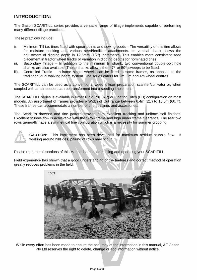
INTRODUCTION: The Gason SCARITILL series provides a versatile range of tillage implements capable of performing many different tillage practices. These practices include: i). Minimum Till i.e. tines fitted with spear points and sowing boots – The versatility of this tine allows
for moisture seeking and various seed/fertilizer attachments. Its vertical shank allows the adjustment of digging depth in 12.5mm (1/2”) increments. This enables more consistent seed placement in tractor wheel tracks or variation in digging depths for nominated tines.
ii). Secondary Tillage – In addition to the minimum till shank, two conventional double-bolt hole shanks are also available. These shanks allow either 47° or 50° sweeps to be fitted.
iii). Controlled Traffic – In-frame single wheels can be fitted to some frames, as opposed to the traditional dual walking beam system. The series caters for 2m, 3m and 4m wheel centres.
The SCARITILL can be used as a conventional weed kill/soil preparation scarifier/cultivator or, when coupled with an air seeder, can be transformed into a seeding implement. The SCARITILL series is available in either Rigid Pull (RP) or Floating Hitch (FH) configuration on most models. An assortment of frames provides a Width of Cut range between 6.4m (21’) to 18.5m (60.7’). These frames can accommodate a number of tine spacings and accessories. The Scaritill’s drawbar and tine pattern provide both excellent tracking and uniform soil finishes. Excellent stubble flow is achievable with the 5-row frame and high under frame clearance. The rear two rows generally have a symmetrical tine configuration which is a necessity for summer cropping.
CAUTION: This implement has been developed for maximum residue stubble flow. If working around hillsides, pairing of rows may occur.
Please read the all sections of this Manual before assembling and operating your SCARITILL. Field experience has shown that a good understanding of the features and correct method of operation greatly reduces problems in the field.
While every effort has been made to ensure the accuracy of the information in this manual, AF Gason
Pty Ltd reserves the right to delete, change or add information without notice.
1303

Page 7 of 38
Note: Additional attachments such as anhydrous ammonia tanks and prickle chains, which may place significant loads on the frame, will void warranty on the frame and any related components. Approved attachments include Gason coulters, press wheels, spring tine harrow
assemblies and parallelogram press wheels on the Hydratill. If unsure as to the warranty implications to any attachment or modification that you wish to make to your SCARITILL, consult your local authorised Gason Dealer.
Note: Reference to the left and right hand sides of the SCARITILL are from the rear of the implement looking forward.
Left and right hand: All references in this manual are determined by facing the direction of travel.
Serial No. tag at left hand rear of Centre Frame.
Subject to any applicable Federal, State or Territory laws or ordinances which may apply from time to time. AF Gason Pty Ltd reserves the right to make changes in design and specifications without notice
or obligation and to change or discontinue models at any time without incurring any liability to any Purchaser thereof.
For warranty provisions please consult your Installation and Warranty Registration document.
1301 RIGHT HAND LEFT HAND
1291
Page 8 of 38
SAFETY:
The SCARITILL has been designed with safety in mind. However, the equipment is only as safe as the person operating it. Do not operate the SCARITILL until you have read and understood this manual. If you feel you need help or advice with the operation of the implement, contact your local authorised Gason Dealer. To ensure trouble free and safe operation of your implement, it is important to carry out a daily safety check to reduce the possibility of a costly breakdown. Items to Check Daily During Operation Check that all hardware is tight, especially during the first couple of days of working or after
transportation. Check all tyre pressures and tyre conditions in general. Check for mud/stubble build-up, especially around the wheels, tines and sowing boot regions. Check that all hydraulic breakaway connections are locked into position. Check all hydraulic cylinders, hoses and fittings for leaks and wear. Check all ground tools/spear points for fitment and wear. Check the drawbar pins and safety chains for wear. General Safety Conditions Check that all controls and operating functions of the implement in a safe area before
commencing work. Ensure that all persons are safely clear of implement before connecting to the tractor hitch,
operating the implement or folding the wings. DO NOT ride on the implement when operating. DO NOT adjust hydraulic fittings while under pressure. When servicing under or around implement, ensure that proper precautions are taken to stabilise
and secure the implement. Carry out the daily safety checks and operate the implement in a safety conscious manner. Hydraulics Before working on the hydraulic system always check that no pressure exists in the system. Never attempt to disconnect a breakaway coupling if the hydraulic circuit is pressurised. For further information and tips on hydraulics, see the “Hydraulic System” section. Leaving the SCARITILL unattended Before disconnecting the tractor drawbar pin and hydraulic breakaways, lower the implement
such that the tines are resting at ground level and are taking the weight of the implement. If this cannot be done, the wheels should be chocked to prevent the SCARITILL from rolling.
Page 9 of 38
Transporting and Working the SCARITILL Ensure that both castor wheels are pinned when transporting. Failure to do this will result in
excessive castor wheel tyre wear and severe implement instability. These pins must be removed before working the implement.
DO NOT EXCEED 20km/h when transporting the SCARITILL. Reduce tractor speed when
transporting over uneven or rough terrain. Note all hazards such as ditches, contour banks, overhead power lines, narrow gates, fences etc., when transporting and/or operating the implement. Ensure safety tow chains are coupled between each piece of machinery.
Check centre frame wheel pressures are at maximum prior to any road transport. Refer “Tyre
Care” section. Be aware of the implement’s limitations with regard to negotiating abrupt changes in ground
terrain and take appropriate precautionary action in such circumstances. Do not work implement in rocky outcrops. Whilst the tine has jumping ability, it does have
limitations and these should be recognized. Excessive numbers of rocks, large rocks or reefs should all be avoided. Damage to the implement in such conditions, including accessories such as press wheels and coulters, will NOT be covered by warranty.
For further information and helpful tips on transporting and working, see the “Operating the
Scaritill” section.

Page 10 of 38
HYDRAULIC SYSTEM: Introduction The hydraulic system of the SCARITILL consists of two independent circuits i.e. depth control and wing fold. The hydraulic circuits should be able to operate for extended periods with minimal maintenance. A storage bracket equipped with dust caps for the hydraulic hose tips is mounted near the implement hitch to provide some contamination protection for the hydraulic circuits. Hydraulic oil cleanliness is imperative, especially if trouble free performance is expected. Tractor requirements A standard tractor hydraulic system in good working order is all that is required to operate the SCARITILL hydraulics. Ensure the oil flow rate does not exceed 100 l/min (26 US gpm) otherwise pressure spikes may occur in the depth control circuit. Before operating the tractor hydraulics a careful check should be made of the following: - cylinders are correctly located and aligned i.e. the cylinders are not under stress due to
misalignment or tight pins. hoses are correctly connected, firmly fixed and clear of any sharp edges or other obstructions that
may cause pinching or wear on the outside of the hose. no visible leaks from any hydraulic fittings. all hydraulic tubes, hoses and fittings should be regularly inspected for damage and wear. always maintain a high degree of cleanliness when fitting all hydraulic components, tubes, hoses
and fittings. do not over tighten hydraulic fittings. Install and tighten nut finger tight until it bottoms the seat,
then tighten a further 1/3 turn only. all threaded pipe connections should be treated with a thread sealant compatible with hydraulic
systems; e.g. Loctite 569. Only apply sealant to the male threads. Do not use thread sealant on flare type fittings. Note: Always use genuine parts when repairing and maintaining your equipment. Refer to the Spare Parts Manual for component details.

Page 11 of 38
Wing Fold Circuit The wing fold circuit comprises of a number of double acting cylinders, and restrictors. The circuit may have a flow divider fitted which should allow all cylinders to operate simultaneously. Some models may also include a dual over-centre valve which stops folded wings inadvertently unfolding. Depth Control Circuit The depth control circuit found on the implement consists of a master/slave rephasing cylinder system connected in series. The master/slave system means that the rod end of the largest (master) cylinder is connected to the base of the first slave cylinder, and then the rod of the first slave cylinder is connected to the base of the second slave cylinder. The sizes of the cylinders and rods are matched such that a certain extension of the larger cylinder will displace a volume of fluid (from the rod end), which will match the volume required by the next cylinder (at its base end) to extend the same distance. These rephasing cylinders have a valve within the piston that allows oil to pass through the piston when it is fully extended or retracted. The benefits of this feature are twofold i.e. the cylinders are able to re-synchronise (rephase) compensating for any leakage (internal or external) and at the same time purge air from the cylinders and hose back to the tractor as per “Purging hydraulic circuits”. Note: With these rephasing cylinders, it is NOT necessary to remove hoses or fittings to achieve bleeding of the depth control circuits. To allow the rephasing system to work correctly, all air must be purged from the system. Air within the system may exhibit any of the following symptoms: - spongy feel. erratic movement of cylinders. hoses vibrate and squeal. control valve handle shudders. A dual-pilot check valve is mounted near the tractor hitch which allows the hydraulic couplings to be disconnected from the tractor whilst the circuit is under pressure.
Page 12 of 38
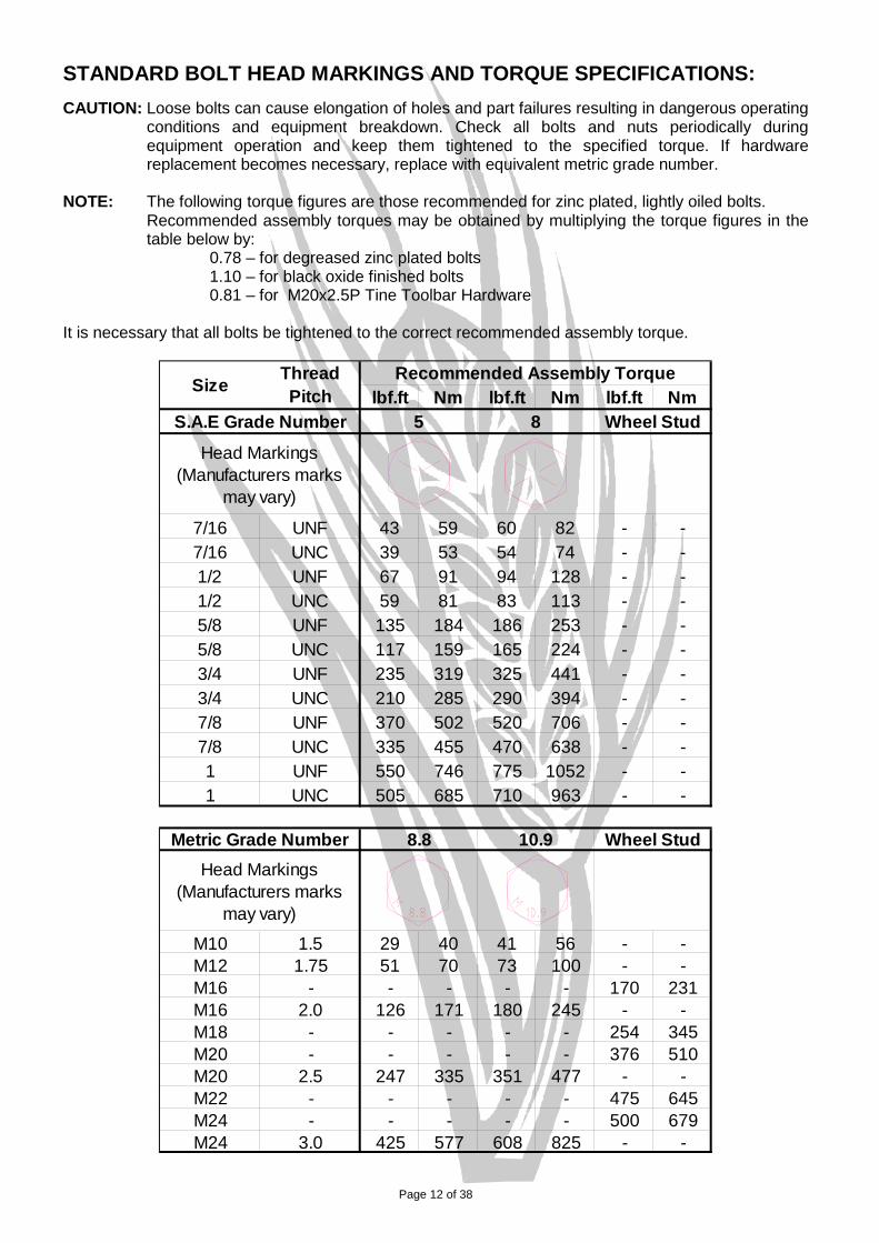
STANDARD BOLT HEAD MARKINGS AND TORQUE SPECIFICATIONS: CAUTION: Loose bolts can cause elongation of holes and part failures resulting in dangerous operating
conditions and equipment breakdown. Check all bolts and nuts periodically during equipment operation and keep them tightened to the specified torque. If hardware replacement becomes necessary, replace with equivalent metric grade number.
NOTE: The following torque figures are those recommended for zinc plated, lightly oiled bolts.
Recommended assembly torques may be obtained by multiplying the torque figures in the table below by:
0.78 – for degreased zinc plated bolts 1.10 – for black oxide finished bolts 0.81 – for M20x2.5P Tine Toolbar Hardware
It is necessary that all bolts be tightened to the correct recommended assembly torque.
lbf.ft Nm lbf.ft Nm lbf.ft Nm
7/16 UNF 43 59 60 82 - -7/16 UNC 39 53 54 74 - -1/2 UNF 67 91 94 128 - -1/2 UNC 59 81 83 113 - -5/8 UNF 135 184 186 253 - -5/8 UNC 117 159 165 224 - -3/4 UNF 235 319 325 441 - -3/4 UNC 210 285 290 394 - -7/8 UNF 370 502 520 706 - -7/8 UNC 335 455 470 638 - -1 UNF 550 746 775 1052 - -1 UNC 505 685 710 963 - -
M10 1.5 29 40 41 56 - -M12 1.75 51 70 73 100 - -M16 - - - - - 170 231M16 2.0 126 171 180 245 - -M18 - - - - - 254 345M20 - - - - - 376 510M20 2.5 247 335 351 477 - -M22 - - - - - 475 645M24 - - - - - 500 679M24 3.0 425 577 608 825 - -
Head Markings (Manufacturers marks
may vary)
Recommended Assembly Torque
8.8 10.9 Wheel StudMetric Grade Number
S.A.E Grade Number 5 8
Size Thread Pitch
Wheel StudHead Markings
(Manufacturers marks may vary)

Page 13 of 38
ASSEMBLY INSTRUCTIONS: The SCARITILL is assembled at the factory as much as is practicably possible. When assembling components, hardware should be torqued to the figures in the “Standard Bolt Head Markings and Torque Specification” section. It is recommended to lightly oil the hardware before assembly to obtain more consistent torque loadings. Lifting the SCARITILL from the truck Ensure the all lifting equipment is in good condition and has the capacity to lift the load. To avoid excessive paint damage, the use of soft slings and shackles is recommended, but if chains must be used, ensure paintwork is protected. SCARITILL weights The following table can be used as a guide to your machine’s total weight. Scaritill weights do not include optional attachments and are based on 250mm tine spacings. e.g. Total approx. weight of a SMFHDF63-250 with qty 63 coulters and frame-mounted press wheels:
11000 + (63x40) + (63x40) = 16040kg
Description Approx. Weight [kg]
Scaritill – 8m width of cut, single fold. 7000 Scaritill – 12m width of cut, single fold. 8000 Scaritill – 15m width of cut, single fold. 9000 Scaritill – 15.5m width of cut, double fold. 11000 Scaritill – 18m width of cut, double fold 16000 Tine assembly (400lb spring) 55 Parallelogram/Tine assembly 95 Coulter assembly 40 Frame-mounted press wheel assembly 40 Spring tine harrows 70kg/m
Frame Assembly. Upon dismantling the frames from their transport stacks, position frames on level ground near to the assembled state. Additional supports may be required to support the frames in conjunction with lower transport stands supplied. Refer to the Spare Parts Manual to familiarise yourself with frame locations. Frames If not already assembled, loosely attach all frames and related braces at connection points. Attach wing frames to the centre frames with the hinge pins and hardware supplied. If the implement is a floating hitch model, tighten centre frame, wing sections and related braces. Connector Bars The connector bars linking the rockshaft/crankarm to the front castor wheels are factory set to a nominal length, as detailed in the “Adjustments” section of the “Operating the Scaritill” section. The length of the connector bars may require some adjustment in order to level the implement. The connector bars mount from the plate on the top of the rockshaft/crankarm to the castor wheel’s lower linkage arm. Refer to “Assembly - Centreframe” in the Spare Parts Manual for more information. Drawbar - Rigid Pull. Loosely connect the drawbar members to the front and rear centre frames (and to each other, if applicable), at each connection plate with the hardware supplied. Tighten centre frame, wing sections and related braces, if required. Visually check drawbar squareness to the centre frame before tightening drawbar connections. Fit hitch tongue assembly, drawbar jack and safety tow chain. - Floating Hitch. Attach the right-hand pull member onto the front centre frame, being careful not to damage the internal surface of the bush, followed by the left-hand member. Connect the two together at the hitch tongue with the Ø32mm pins and lynch pins supplied. Connect each of the pull braces to the side pull members with the hardware supplied. Note: Secure all brace hardware hand tight only, then check all components are centrally aligned before fully tightening. Fit drawbar jack and safety tow chain.
Page 14 of 38
Toolbox Locate the toolbox on the left hand side of the pull brace using the 2 off M16 100 x 100 U-Bolts and 4 off M16 Nyloc Nuts. Castor Wheel Assemblies The castor wheel assemblies should be supplied with the hardware to secure them into the frames. Refer to “Assembly - Centreframe” in the Spare Parts Manual for detail of hardware location. Hydraulic Circuit In setting up the hydraulic circuit, it is imperative that the cylinders are correctly located and aligned. Likewise, the plumbing of the hoses must be connected to produce the correct circuit and that care is taken to maintain cleanliness of the system. Similarly, when securing the hydraulic hoses to the frames, care needs to be taken to ensure that sufficient slack is provided in areas where a pivot joins members or the connection is to a moving component. There should be sufficient hose length to “loop” the hose at wing hinge pivot points.
Note: Before operating the hydraulics, read and understand the “Hydraulic System” section. Hose ends to be connected to the tractor are fitted with ½” BSPT male fittings and are supplied with ½” quick release breakaways.
- Depth Control. The depth control circuit consists of master/slave cylinders in series. The working depth of the implement can be limited with mechanical depth stops fitted to the master cylinder/s. A pressure relief valve is used to limit the retract pressure of the depth control circuit to 10.3MPa (1500psi). This is done to protect the cylinder depth stop plates from excessive load. Transport locks are provided for the centre frame cylinders for use when transporting or working under the machine. Route and connect the circuit as shown in “Hydraulic Circuit – Depth Control” in the Spare Parts Manual. - Priming the Depth Control Circuit. Note: Ensure the tractor’s hydraulic flow rate to the implement is between 45 and 100 l/min (12 to 26 US gpm). If the hydraulic flow rate is less than 45 l/min, the time to change the implement’s depth may not be acceptable. If the hydraulic flow rate is greater than 100 l/min, pressure spikes may occur. After checking all hardware is tight and no potential foul situation seems likely near wheels or stands, connect the depth control circuit to the tractor. The following procedure should be adopted to achieve complete removal of air from the depth control system: - 1. Warm tractor engine, then set at idle. 2. Actuate tractor hydraulics to fully extend or fully retract implement cylinders, (rephasing
positions), and hold for 2 minutes. This should be enough time for all the air within the circuit to be dumped into the tractor reservoir.
3. Maintain a close watch on tractor oil level and top-up with new clean oil as required, (not aerated
oil). Observe closely as too low an oil level may introduce more air into the system. 4. Fully retract implement cylinders and hold for another 2 minutes. They should operate
simultaneously and evenly. If not, repeat steps 2, 3 and 4 again.

Page 15 of 38
- Wing Fold. A hydraulic circuit is employed to fold the wings from the working position for transport or storage. This circuit is independent of the depth control circuit. The wing fold circuit consists of a number of non-phasing double acting cylinders connected in parallel. On double-fold models, the circuit has been designed and cylinders sized, such that when folding for transport or storage, both the outer wings will fold until coming to rest on the stops on the inner wings, then the inner wings will fold until coming to rest on the centre frame stops. When unfolding for working, both the inner wings will unfold until the wheels come to rest on the ground, then the outer wings will unfold until coming to rest on the ground. Always ensure that the wingfold cylinders are fully extended when working or transporting with the wings unfolded. Route and connect the circuit as shown in “Hydraulic Circuit – Wing Fold” in the Spare Parts Manual. - Connecting and Priming Wing Fold Cylinders. Refer to “Wing Fold Hardware” in the Spare Parts Manual for details on hardware and clevis location.
1. Secure the base end of the wingfold cylinders to their anchors. 2. Using suitable blocks, support the rod end of the wing fold cylinders ensuring that the rods will
have freedom to fully extend without fouling anything. 3. Warm tractor engine, then set at idle. 4. Actuate tractor hydraulics to slowly fully extend implement wingfold cylinders. 5. Maintain a close watch on tractor oil level and top-up with new clean oil as required, (do not add
aerated oil). Observe oil level closely, as too low an oil level may introduce more air into the system.
6. A flow divider is included on most models and at full extension or retraction they should allow all
cylinders to re-synchronize, i.e. continue to actuate hydraulics for this to occur.
7. Fully retract and extend these cylinders until all cylinders work simultaneously and evenly. 8. At full retraction, check that all cylinder clevises have been fitted to the correct length.
DESCRIPTION DIMENSION “X” (mm) 30” Stroke Cylinder – Short Cylinder Eye 1220.3 +1, -2 30” Stroke Cylinder – Long Cylinder Eye 1294.1 +1, -2 36” Stroke Cylinder – Short Cylinder Eye 1372.7 +1, -2 36” Stroke Cylinder – Long Cylinder Eye 1446.5 +1, -2
9. Upon removal of a cylinder fitting, always repeat the procedure for complete removal of air from
the system before connecting cylinder eyes to the wing anchors 10. Fully extend the cylinders and secure to the wing anchors. Ensure the bush is positioned inside
each cylinder eye and can freely rotate
Page 16 of 38
Tine Fitment Tine location decals (arrows) should be fitted to the toolbar to indicate the tine locations for tines not fitted or not fitted in the correct location. Upon fitment of these tines, ensure the correct hardware is used i.e. M20 Grade 8.8 bolts and Class 8 Nyloc nuts. Secure the four fasteners in stages to pull up the tine evenly and squarely onto the toolbar.
Note: Assembly torque settings are critical to ensure tine assemblies remain secure to the toolbar at all times. Torque to 200 lbf.ft. (271 Nm). Confirm this setting with a good quality torque wrench.
Tines mounted to the frames should be in their correct locations for the spacing ordered. Before working, check all tine locations with the relevant tine layout. Ensure tines are mounted square to the toolbars – refer to “Tine Adjustments” in the “Operating the Scaritill” section. Shank Fitment Once the implement is fully raised off its stands, fit the tine shanks to the upper tine assemblies. Ensure positioning pins are in the same hole in both the shank and the pivot bracket to the tine tower. Also ensure the rear M20 set screws are tightened up hard against the shank and the locking nut is then tightened. Refer to the “Tine Assembly" in the Spare Parts Manual for hardware location. Once all tine shanks are fitted, the frame support stands can be removed. Groundtool Fitment There are a growing range of ground engaging tools available to suit the range of Scaritill shanks. Selection of the most appropriate groundtool will depend on your agricultural practice, ground conditions, attachment (if any) and sowing boot design. Regardless of the tool selection, be aware that the further forward the tool tip is relative to the tine pivot, the tine’s jump height will be adversely affected. Beware; the tool tip must always be behind the tine pivot, otherwise: Tine jump height will be dramatically reduced. The tool will initially dig deeper during the jump cycle.
Double bolt shank groundtools are more prevalent to the above condition. Final Pre-Delivery Check List After the SCARITILL has been assembled, a final check should be carried out before delivery: 1. Check that all hardware is in place and is tight. Refer to “Standard Bolt Head Markings and
Torque Specifications” section for assembly torques. 2. Check the tyre pressures of all tyres. Refer to “Tyre Care” in the “General Maintenance” section
for details. 3. Check that the hydraulics are primed and bled of all air as detailed in “Purging the hydraulic
circuits” in the “Hydraulic System” section. 4. Check that all hydraulic hoses are routed to accommodate working angles between implement
members joined by pivots, checking for potential pinching, fouling or rubbing of hoses. 5. Check that all tines are in their correct location and mounted square to the toolbar. 6. Check that all accessories do not foul with implement wheels or framework through their
working/transporting range. 7. Check all hydraulic connections for leaks. 8. Check safety tow chain is fitted to implement. If additional length is required, use only Grade 80
tow equipment.
Page 17 of 38
TRANSPORTING:
Once the SCARITILL has been fully assembled with the hydraulics primed, it is ready to transport. The SCARITILL should always be transported in the fully raised position with the wings completely folded and transport locks in place. Never travel with wings in any other position except fully up or down.
BEWARE of tines and/or accessories fouling on tyres when lowering implement with wings folded and no shanks fitted. Check both the centreframe and inner wing wheels. BEWARE of power lines and other obstructions when transporting with wings folded.
Before towing on the road, consult the appropriate state or local authority for any specific regulations and permits that may be required e.g. dimensions, weight, time of day, road and bridge restrictions, area category etc. Avoid transporting the SCARITILL long distances. Maximum transport speeds should not exceed 20 km/h. Reduce speed when travelling over rough terrain and shift into low gear down steep slopes.
It is recommended to have the tractor and airseeder (for front tow seeders) drawbar fixed centrally during road transport to provide greater stability. DO NOT TOW: with any person or persons riding on the implement. in a dangerous manner that may threaten the safety of any person. through excessively undulating terrain which may cause potentially dangerous implement
instability. Tips to remember when towing: 1. It is recommended that the centre frame wheels have the tyre pressure increased to the
maximum, refer to “Tyre Care” in the “General Maintenance” section, when towing on a hard surface for any extended lengths of time. Doing so will prevent excessive tyre side wall heat and distortion and rapid tyre wear occurring.
2. Use a drawbar pin that is the correct size to reduce any jarring action.
3. The safety tow chain must be fitted around a substantial part of the tractor or towing implement and hooked back onto itself. Ensure hook safety catch is engaged. The chain must be fitted to allow normal angular movement of the coupling without unnecessary slack. Ensure the chain is free of twists and protected from sharp corners. If practicable, the chain must be connected so the drawbar of the implement is prevented from hitting the ground if the coupling accidentally detaches. If towing a combination of implements, ensure safety chain tow capacity is adequate. An additional chain may be required.
4. After transporting for a few kilometres, stop and check all wheel nuts, connector bars, clevis pins, lynch pins and lock nuts. This should be repeated again if transporting any extended distances. In particular, wheel nuts can work loose until they have bedded in. Hence, wheel nuts need to be checked regularly in accordance with “STANDARD BOLT HEAD MARKINGS AND TORQUE SPECIFICATIONS” before and during any period of operation
5. On floating hitch models: If castor wheel instability during transportation is extreme, the castor
action can be fixed by engaging the transport locking pins at the front of the castor. Failure to do this will result in excessive castor wheel tyre wear and severe implement instability. Ensure pins are removed prior to working. Refer to “Assembly - Centreframe” in the Spare Parts Manual for details.Torsion bars mount to underside of toolbar. Castor wheel stability can be improved by increasing the load on the torsion bars by screwing down the adjusting bolt.
6. On floating hitch models: Additional forward ballast can be obtained by filling the front castor wheels with water. Refer to “Tyre Care” in the “General Maintenance” section for ballast details.
Page 18 of 38
OPERATING THE SCARITILL: The design of your SCARITILL provides flexibility in tine spacings, tine layouts, individual working depths, ground engaging tools and provision for a multitude of attachments, allowing its use for more than just one application or practice. Regardless of the practices being employed, there are a number of general rules that should be followed when working the SCARITILL. 1. Whenever starting or stopping, the tines should always be out of the ground. When commencing
work, move off slowly and lower the implement to the required depth; then increase to the desired working speed (up to a maximum recommended speed of 10 km/h).
2. Do not turn too sharply whilst tines are in the ground as this will place excessive loads on the tines, ground tools and frame. Tines must be raised out of the ground when turning at headlands or in other tight situations.
3. Do not work with the wings folded, whether partially or completely. Ensure wing fold cylinders are always fully extended when operating.
4. Become familiar and aware of the limitation of the implement and work within these limits. It is your responsibility to assess your specific application and determine the risks involved and appropriate action.
5. Upon selecting the desired working depth, set the depth stop mechanism to control the height as per “Adjustments – Depth Stop” in the “Operating the Scaritill” section. In conjunction, set the depth indicator such that the two reflectors line up with each other. Once set, work implement for approximately 100m and check depth consistency. Adjust as necessary.
6. Whilst working, regularly observe the depth indicator for any signs of variation and keep observing the entire implement for any blockages of mud, stubble or any other obstructions.
7. Avoid working on excessively steep slopes or rocky terrain. Such conditions place extreme loads on the implement and will dramatically reduce its working life.
8. The tines are designed to trip when encountering an obstacle. The implement should never be
worked with the tine shank constantly laying back from vertical or jumping. This may cause premature, abnormal wear of the tine assembly. SUCH WEAR WILL NOT BE COVERED UNDER WARRANTY. Working in this manner will also increase the loads placed on the implement frame and increase tractor fuel consumption. In addition, the correct ground tool working angle and consistent depth control will not be maintained. If such a situation persists, the load on the tine must be reduced by: - decreasing ground speed - reducing working depth - replacing groundtool with one which produces less draft - shortening the tine shank by sliding up the casting - delay working until more suitable soil conditions prevail
Before operating the SCARITILL for the first time, check that all components have been fitted and that the implement is ready for use. Refer to the checklist in the “Assembly Instructions”. - Tractor Preparation: Check that the tractor hydraulics are functioning correctly and the hydraulic fluid reservoir is full. This is due to the volume of fluid required to fill all cylinders and hoses when connecting a new implement. The presence of air in the hydraulic circuits will cause the implement to operate erratically and is potentially very dangerous when folding wings or transporting the implement. The hydraulic systems on the implement are designed to handle a maximum working pressure of 17.2 MPa, (2500 psi). The tractor hydraulic flow rate must be set between 45 and 100 l/min, (12-26 US gpm).
Page 19 of 38
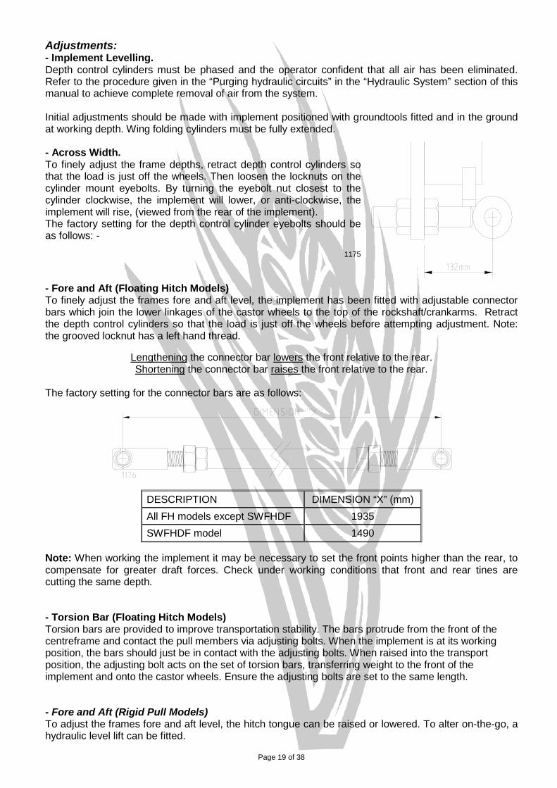
Adjustments: - Implement Levelling. Depth control cylinders must be phased and the operator confident that all air has been eliminated. Refer to the procedure given in the “Purging hydraulic circuits” in the “Hydraulic System” section of this manual to achieve complete removal of air from the system. Initial adjustments should be made with implement positioned with groundtools fitted and in the ground at working depth. Wing folding cylinders must be fully extended. - Across Width. To finely adjust the frame depths, retract depth control cylinders so that the load is just off the wheels. Then loosen the locknuts on the cylinder mount eyebolts. By turning the eyebolt nut closest to the cylinder clockwise, the implement will lower, or anti-clockwise, the implement will rise, (viewed from the rear of the implement). The factory setting for the depth control cylinder eyebolts should be as follows: -
1175 - Fore and Aft (Floating Hitch Models) To finely adjust the frames fore and aft level, the implement has been fitted with adjustable connector bars which join the lower linkages of the castor wheels to the top of the rockshaft/crankarms. Retract the depth control cylinders so that the load is just off the wheels before attempting adjustment. Note: the grooved locknut has a left hand thread.
Lengthening the connector bar lowers the front relative to the rear. Shortening the connector bar raises the front relative to the rear.
The factory setting for the connector bars are as follows:
DESCRIPTION DIMENSION “X” (mm) All FH models except SWFHDF 1935 SWFHDF model 1490
Note: When working the implement it may be necessary to set the front points higher than the rear, to compensate for greater draft forces. Check under working conditions that front and rear tines are cutting the same depth. - Torsion Bar (Floating Hitch Models) Torsion bars are provided to improve transportation stability. The bars protrude from the front of the centreframe and contact the pull members via adjusting bolts. When the implement is at its working position, the bars should just be in contact with the adjusting bolts. When raised into the transport position, the adjusting bolt acts on the set of torsion bars, transferring weight to the front of the implement and onto the castor wheels. Ensure the adjusting bolts are set to the same length. - Fore and Aft (Rigid Pull Models) To adjust the frames fore and aft level, the hitch tongue can be raised or lowered. To alter on-the-go, a hydraulic level lift can be fitted.

Page 20 of 38
- Depth Control. Setting the implement’s working depth is achieved by the following procedure: 1. Back off the bolts retaining the mechanical depth stops on each of the master cylinders to allow
the cylinders to fully retract 2. Raise and lower the implement a couple of times, allowing the cylinders to fully extend and
rephase. Refer to “Depth Control Circuit” in the “Hydraulic System” section for details. 3. Engage the implement to the required working depth and operate for 50-100 metres. 4. Adjust cylinder depth stop until at rest on the cylinder end cap, ensuring that both halves of the
depth stop are secured level and both master cylinder depth stops are set the same. As a check, count the number of teeth exposed on each depth stop half.
- Castor Wheel Frame Adjustment The castor wheel frames should be able to rotate 360° with minimal rotational resistance. This resistance can be adjusted via the torque setting on the vertical castor pivot retaining nut. Caution: The castor wheel frame may foul the lower linkage arm when the implement is lowered without shanks and the castor frame not pinned. - Tine Adjustment. The SCARITILL tine shank height can be adjusted vertically with the lowest setting gives 760mm (30”) underframe clearance. The shank can be adjusted in 12.5mm (1/2”) increments up to a minimum under frame clearance of 660mm (26”). Tines should be secured to the toolbar squarely i.e. the shanks should be vertical. By tightening the mounting hardware in stages when the tines are being secured to the toolbar, this will help to keep the tine and tine clamp orientated correctly. Note: The tine breakout force increases as the underframe clearance (UFC) is reduced. e.g. 380lbf @ 760mm UFC, 420lbf @ 660mm UFC. (figures are based on the “400lb” spring) The implement should never be worked with the tine shank constantly jumping or laying back from the vertical. This may result in premature wear of the tine assembly and will not be covered under warranty. Refer “Working the Scaritill” for more detail. OPTIONAL ATTACHMENTS: Spring Tine Tower Cover Plate Tines, which are located immediately behind one of the implement wheels, may be subject to a build-up of mud or other matter within the tower. A cover plate is available to provide adequate protection in such circumstances. Refer to “Tine Assembly” in the Spare Parts Manual for an illustration. Mudscrapers Most models have mudscrapers available. Refer the Spare Parts Manual. To improve the wheels’ mud shedding ability, tyre pressures can be reduced. However, care must be taken to ensure the tyres are not overstressed whilst turning or during road transport. Parallelograms, Presswheels, Harrows or Coulters There should be adequate provision for the attachment of spring tine harrow assemblies to be mounted on the rear row of your SCARITILL, in conjunction with a trailed air seeder. Tine and frame mounted presswheels, coulters and parallelograms (on the Hydratill) should be checked for wheel and/or frame clearance throughout their working and transportation range.
Be cautious of attachments fouling on rear tow air seeders when turning.
Page 21 of 38
GENERAL MAINTENANCE: Introduction Your SCARITILL has been designed with minimum maintenance in mind, however regular maintenance will ensure trouble free operation for the life of the implement. It is recommended that when replacing parts you use genuine components and fasteners of the same grade and quality as the ones used on the original implement. DO NOT COMPROMISE SAFETY WITH FAULTY COMPONENTS. Pre-Season Checklist Check all tyre pressures, referring to “Tyre Care” in the “General Maintenance” section for details. Check all hydraulic hoses and fittings for any signs of hydraulic leaks. Randomly check the tension on fasteners across the implement, especially those related to the
tines. Daily Checklist 1. Hydraulics.
Check all hydraulic fittings and components for any signs of external leaks. Keep hydraulic hose tips clean. Check depth control circuit remains phased.
2. Wheel Nuts.
Check tension on all wheel nuts when first working or transporting the SCARITILL in accordance with the “STANDARD BOLT HEAD MARKINGS AND TORQUE SPECIFICATIONS”, after assembly, or if a wheel has been fitted. This need only be done for the first couple of days of operation, unless extended transportation occurs.
3. Tine Assemblies.
Check tension on the tine toolbar mount hardware. This need only be done for the first couple of days of operation until the tine settles in. Note: This hardware is Grade 8.8.
Check the state of ground tool hardware to ensure spear points/sweeps remain tight and in place.
Check sowing boot, if fitted, for blockages, damage or excessive wear. 4. Wheel Assemblies.
Check for mud and/or stubble build-up around tyres and clear as necessary to reduce the likelihood of excessive tyre wear.
Weekly Checklist 1. Hydraulics.
Inspect all hydraulic hoses for external wear. 2. Tine Assemblies.
Check the tension on tine shank to pivot bracket hardware i.e. M20 set screws and nuts. Check ground tool wear and/or damage - replace as required.
Note: When replacing ground tools, it is recommended to replace the relevant hardware with genuine new parts at the same time. Refer to “Tine Assembly” and “Shank Options” in the Spare Parts Manual for details.
Page 22 of 38
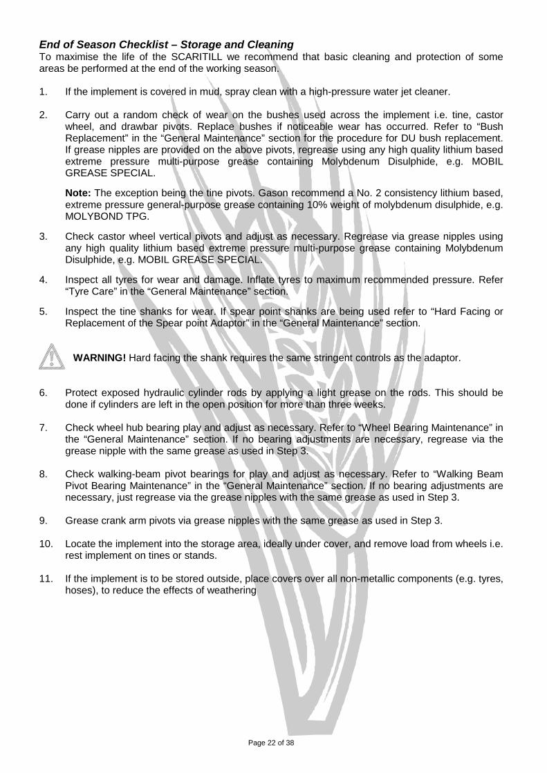
End of Season Checklist – Storage and Cleaning To maximise the life of the SCARITILL we recommend that basic cleaning and protection of some areas be performed at the end of the working season.
1. If the implement is covered in mud, spray clean with a high-pressure water jet cleaner. 2. Carry out a random check of wear on the bushes used across the implement i.e. tine, castor
wheel, and drawbar pivots. Replace bushes if noticeable wear has occurred. Refer to “Bush Replacement” in the “General Maintenance” section for the procedure for DU bush replacement. If grease nipples are provided on the above pivots, regrease using any high quality lithium based extreme pressure multi-purpose grease containing Molybdenum Disulphide, e.g. MOBIL GREASE SPECIAL.
Note: The exception being the tine pivots. Gason recommend a No. 2 consistency lithium based, extreme pressure general-purpose grease containing 10% weight of molybdenum disulphide, e.g. MOLYBOND TPG.
3. Check castor wheel vertical pivots and adjust as necessary. Regrease via grease nipples using
any high quality lithium based extreme pressure multi-purpose grease containing Molybdenum Disulphide, e.g. MOBIL GREASE SPECIAL.
4. Inspect all tyres for wear and damage. Inflate tyres to maximum recommended pressure. Refer
“Tyre Care” in the “General Maintenance” section. 5. Inspect the tine shanks for wear. If spear point shanks are being used refer to “Hard Facing or
Replacement of the Spear point Adaptor” in the “General Maintenance” section.
WARNING! Hard facing the shank requires the same stringent controls as the adaptor.
6. Protect exposed hydraulic cylinder rods by applying a light grease on the rods. This should be
done if cylinders are left in the open position for more than three weeks. 7. Check wheel hub bearing play and adjust as necessary. Refer to “Wheel Bearing Maintenance” in
the “General Maintenance” section. If no bearing adjustments are necessary, regrease via the grease nipple with the same grease as used in Step 3.
8. Check walking-beam pivot bearings for play and adjust as necessary. Refer to “Walking Beam Pivot Bearing Maintenance” in the “General Maintenance” section. If no bearing adjustments are necessary, just regrease via the grease nipples with the same grease as used in Step 3.
9. Grease crank arm pivots via grease nipples with the same grease as used in Step 3.
10. Locate the implement into the storage area, ideally under cover, and remove load from wheels i.e.
rest implement on tines or stands.
11. If the implement is to be stored outside, place covers over all non-metallic components (e.g. tyres, hoses), to reduce the effects of weathering
Page 23 of 38
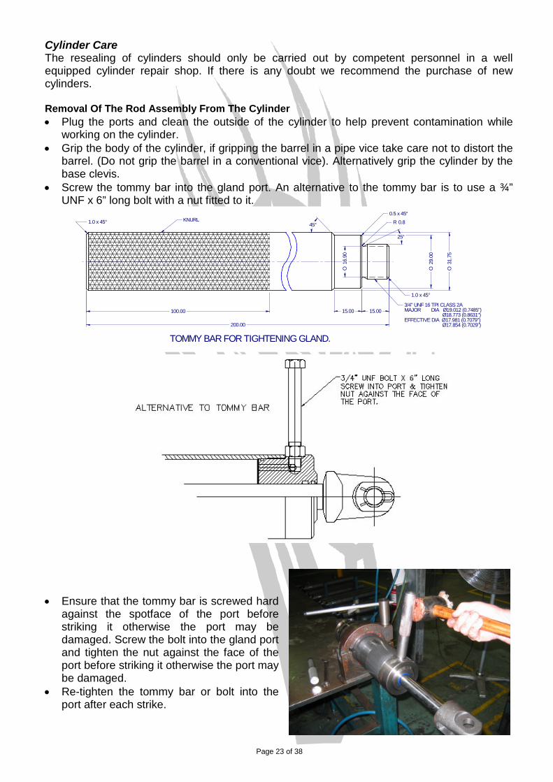
Cylinder Care The resealing of cylinders should only be carried out by competent personnel in a well equipped cylinder repair shop. If there is any doubt we recommend the purchase of new cylinders. Removal Of The Rod Assembly From The Cylinder • Plug the ports and clean the outside of the cylinder to help prevent contamination while
working on the cylinder. • Grip the body of the cylinder, if gripping the barrel in a pipe vice take care not to distort the
barrel. (Do not grip the barrel in a conventional vice). Alternatively grip the cylinder by the base clevis.
• Screw the tommy bar into the gland port. An alternative to the tommy bar is to use a ¾” UNF x 6” long bolt with a nut fitted to it.
29.0
0O
25°
R 0.80.5 x 45°
45°
1.0 x 45°
15.0015.00100.00
200.00
31.7
5O
1.0 x 45°
16.9
0O
3/4" UNF 16 TPI CLASS 2AMAJOR DIA Ø19.012 (0.7485") Ø18.773 (0.8631")EFFECTIVE DIA Ø17.981 (0.7079") Ø17.854 (0.7029")
KNURL
TOMMY BAR FOR TIGHTENING GLAND.
• Ensure that the tommy bar is screwed hard against the spotface of the port before striking it otherwise the port may be damaged. Screw the bolt into the gland port and tighten the nut against the face of the port before striking it otherwise the port may be damaged.
• Re-tighten the tommy bar or bolt into the port after each strike.
Page 24 of 38
• Unscrew the gland by striking the tommy bar or bolt with a copper mallet.
• Fully unscrew the gland and remove the rod assembly, gland and piston from the barrel.
• Protect the rod and barrel assembly from dirt and contamination.
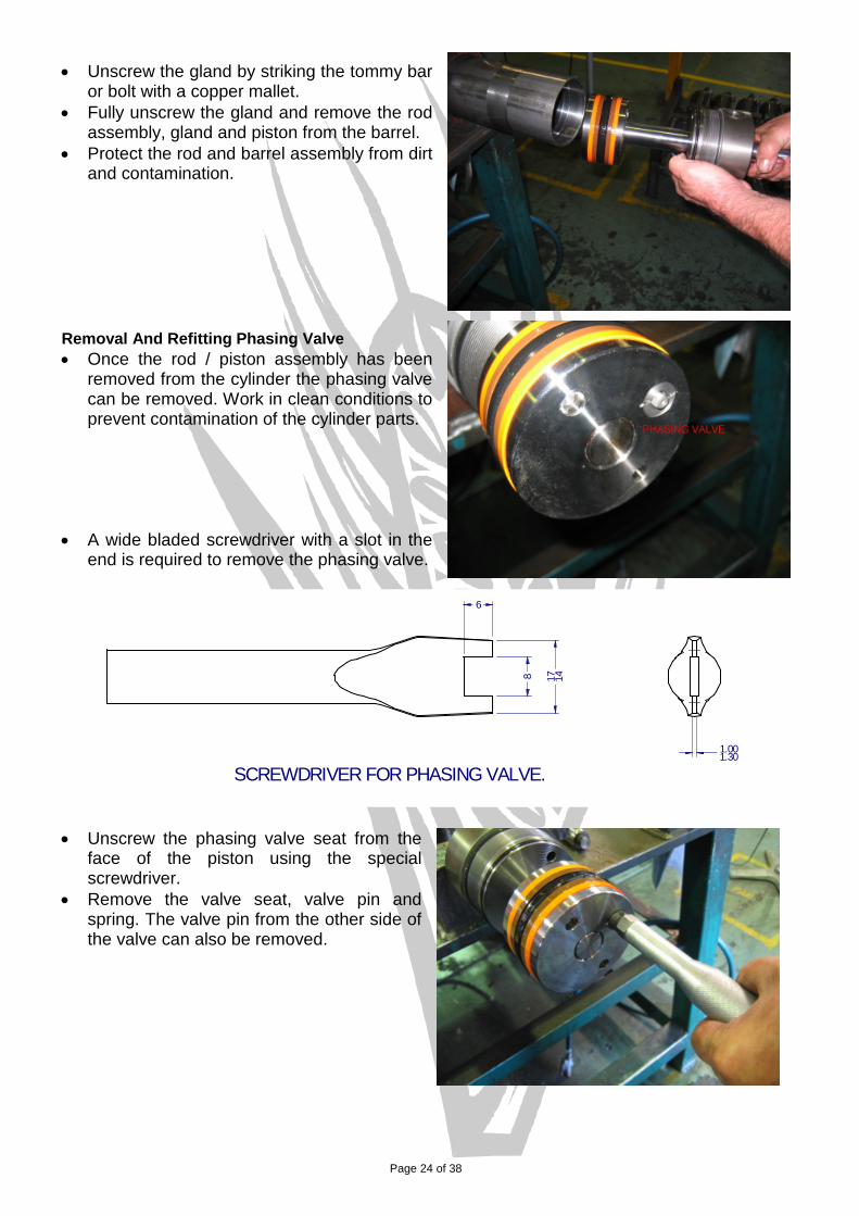
Removal And Refitting Phasing Valve • Once the rod / piston assembly has been
removed from the cylinder the phasing valve can be removed. Work in clean conditions to prevent contamination of the cylinder parts.
• A wide bladed screwdriver with a slot in the
end is required to remove the phasing valve.
1.001.30
8 17 14
6
SCREWDRIVER FOR PHASING VALVE.
• Unscrew the phasing valve seat from the
face of the piston using the special screwdriver.
• Remove the valve seat, valve pin and spring. The valve pin from the other side of the valve can also be removed.
Page 25 of 38
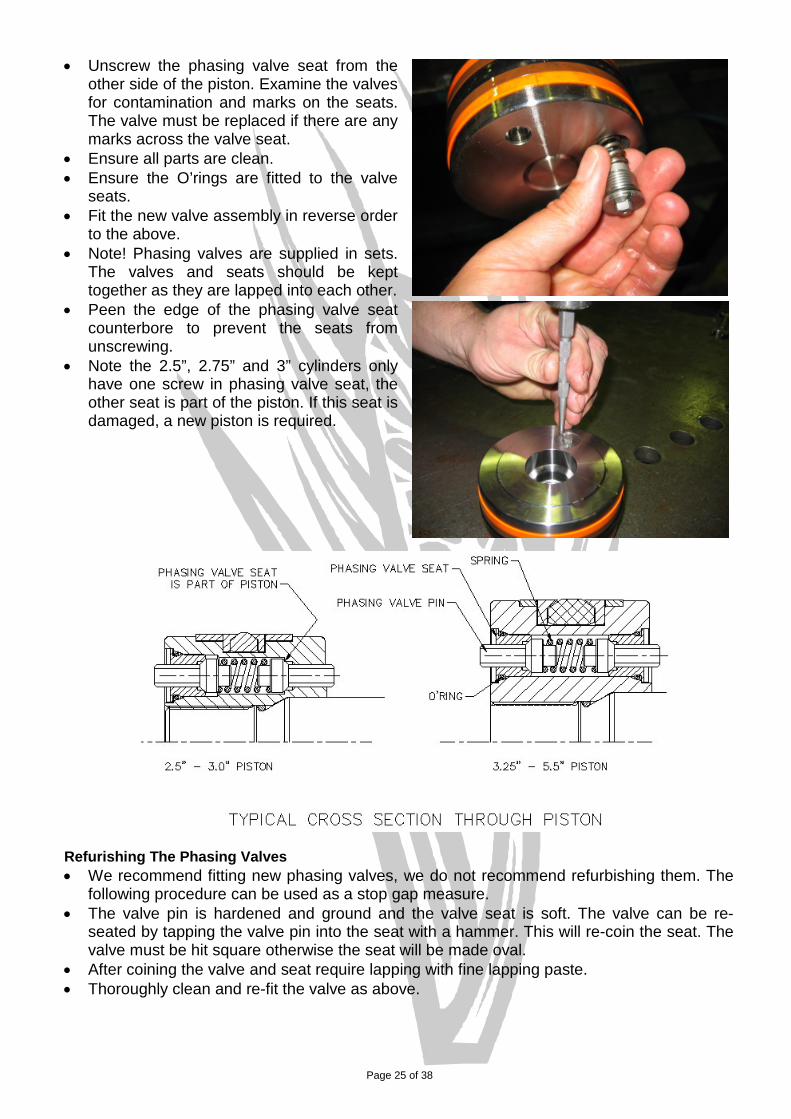
• Unscrew the phasing valve seat from the other side of the piston. Examine the valves for contamination and marks on the seats. The valve must be replaced if there are any marks across the valve seat.
• Ensure all parts are clean. • Ensure the O’rings are fitted to the valve
seats. • Fit the new valve assembly in reverse order
to the above. • Note! Phasing valves are supplied in sets.
The valves and seats should be kept together as they are lapped into each other.
• Peen the edge of the phasing valve seat counterbore to prevent the seats from unscrewing.
• Note the 2.5”, 2.75” and 3” cylinders only have one screw in phasing valve seat, the other seat is part of the piston. If this seat is damaged, a new piston is required.
Refurishing The Phasing Valves • We recommend fitting new phasing valves, we do not recommend refurbishing them. The
following procedure can be used as a stop gap measure. • The valve pin is hardened and ground and the valve seat is soft. The valve can be re-
seated by tapping the valve pin into the seat with a hammer. This will re-coin the seat. The valve must be hit square otherwise the seat will be made oval.
• After coining the valve and seat require lapping with fine lapping paste. • Thoroughly clean and re-fit the valve as above.
Page 26 of 38
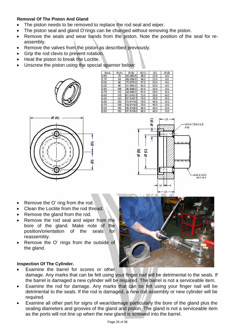
Removal Of The Piston And Gland • The piston needs to be removed to replace the rod seal and wiper. • The piston seal and gland O’rings can be changed without removing the piston. • Remove the seals and wear bands from the piston. Note the position of the seal for re-
assembly. • Remove the valves from the piston as described previously. • Grip the rod clevis to prevent rotation. • Heat the piston to break the Loctite. • Unscrew the piston using the special spanner below:
• Remove the O’ ring from the rod. • Clean the Loctite from the rod thread. • Remove the gland from the rod. • Remove the rod seal and wiper from the
bore of the gland. Make note of the position/orientation of the seals for reassembly.
• Remove the O’ rings from the outside of the gland.
Inspection Of The Cylinder. • Examine the barrel for scores or other
damage. Any marks that can be felt using your finger nail will be detrimental to the seals. If the barrel is damaged a new cylinder will be required. The barrel is not a serviceable item.
• Examine the rod for damage. Any marks that can be felt using your finger nail will be detrimental to the seals. If the rod is damaged, a new rod assembly or new cylinder will be required.
• Examine all other part for signs of wear/damage particularly the bore of the gland plus the sealing diameters and grooves of the gland and piston. The gland is not a serviceable item as the ports will not line up when the new gland is screwed into the barrel.
Page 27 of 38
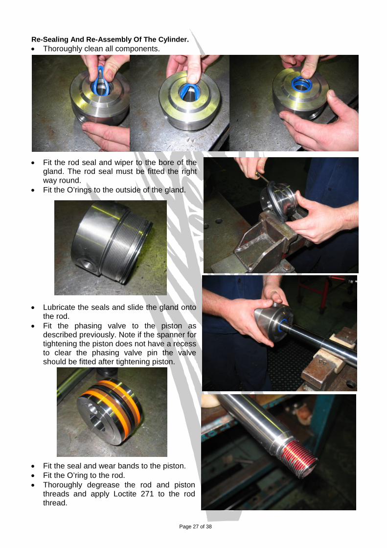
Re-Sealing And Re-Assembly Of The Cylinder. • Thoroughly clean all components.
• Fit the rod seal and wiper to the bore of the gland. The rod seal must be fitted the right way round.
• Fit the O’rings to the outside of the gland.
• Lubricate the seals and slide the gland onto
the rod. • Fit the phasing valve to the piston as
described previously. Note if the spanner for tightening the piston does not have a recess to clear the phasing valve pin the valve should be fitted after tightening piston.
• Fit the seal and wear bands to the piston. • Fit the O’ring to the rod. • Thoroughly degrease the rod and piston
threads and apply Loctite 271 to the rod thread.
Page 28 of 38
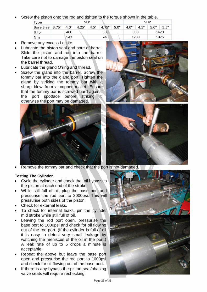
• Screw the piston onto the rod and tighten to the torque shown in the table. TypeBore Size 3.75" 4.0" 4.25" 4.5" 4.75" 5.0" 4.0" 4.5" 5.0" 5.5"ft lbNm
950
SLP SHP
542400
746550
1288 19251420
• Remove any excess Loctite. • Lubricate the piston seal and bore of barrel.
Slide the piston and rod into the barrel. Take care not to damage the piston seal on the barrel thread.
• Lubricate the gland O’ring and thread. • Screw the gland into the barrel. Screw the
tommy bar into the gland port. Tighten the gland by striking the tommy bar with a sharp blow from a copper mallet. Ensure that the tommy bar is screwed hard against the port spotface before striking it, otherwise the port may be damaged.
• Remove the tommy bar and check that the port is not damaged. Testing The Cylinder. • Cycle the cylinder and check that oil bypasses
the piston at each end of the stroke. • While still full of oil, plug the base port and
pressurise the rod port to 3000psi. This will pressurise both sides of the piston.
• Check for external leaks. • To check for internal leaks, pin the cylinder
mid stroke while still full of oil. • Leaving the rod port open, pressurise the
base port to 1000psi and check for oil flowing out of the rod port. (If the cylinder is full of oil it is easy to detect very small leakage by watching the meniscus of the oil in the port.) A leak rate of up to 5 drops a minute is acceptable.
• Repeat the above but leave the base port open and pressurise the rod port to 1000psi and check for oil flowing out of the base port.
• If there is any bypass the piston seal/phasing valve seats will require rechecking.
Page 29 of 38
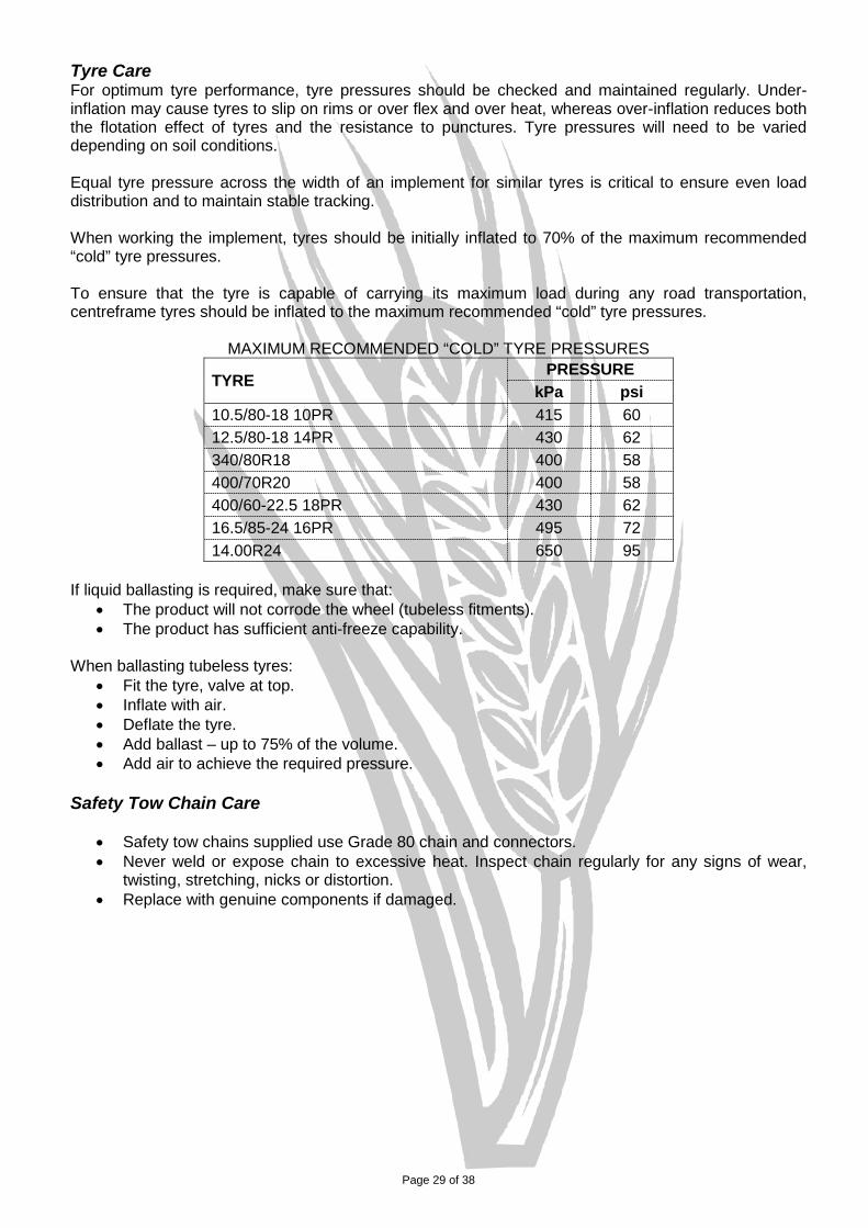
Tyre Care For optimum tyre performance, tyre pressures should be checked and maintained regularly. Under-inflation may cause tyres to slip on rims or over flex and over heat, whereas over-inflation reduces both the flotation effect of tyres and the resistance to punctures. Tyre pressures will need to be varied depending on soil conditions. Equal tyre pressure across the width of an implement for similar tyres is critical to ensure even load distribution and to maintain stable tracking. When working the implement, tyres should be initially inflated to 70% of the maximum recommended “cold” tyre pressures. To ensure that the tyre is capable of carrying its maximum load during any road transportation, centreframe tyres should be inflated to the maximum recommended “cold” tyre pressures.
MAXIMUM RECOMMENDED “COLD” TYRE PRESSURES
TYRE PRESSURE kPa psi
10.5/80-18 10PR 415 60 12.5/80-18 14PR 430 62 340/80R18 400 58 400/70R20 400 58 400/60-22.5 18PR 430 62 16.5/85-24 16PR 495 72 14.00R24 650 95
If liquid ballasting is required, make sure that:
• The product will not corrode the wheel (tubeless fitments). • The product has sufficient anti-freeze capability.
When ballasting tubeless tyres:
• Fit the tyre, valve at top. • Inflate with air. • Deflate the tyre. • Add ballast – up to 75% of the volume. • Add air to achieve the required pressure.
Safety Tow Chain Care
• Safety tow chains supplied use Grade 80 chain and connectors. • Never weld or expose chain to excessive heat. Inspect chain regularly for any signs of wear,
twisting, stretching, nicks or distortion. • Replace with genuine components if damaged.
Page 30 of 38
DU Bush Replacement The self-lubricated bushes used on your SCARITILL are designed to run dry, without any form of additional lubrication. These bushes are used on the castor wheel pivots and linkages, and for the drawbar pivots. However we do grease the castor wheel pivot. The bush is steel, backed with a PTFE (Polytetrafluoroethylene) and lead lined composite bearing material. During normal operation, a thin film from the PTFE lining migrates to the hard chrome pin and remains there throughout the working life of the bearing. If the lubricant layer has worn away, replacement is necessary. The bush is installed in its housing at the factory to the procedure, below. Bushes can be removed by placing a screwdriver on the inside edge of the bush and tapping it outwards (breaking its adhesion). Note: Care must be taken to ensure no damage is done to the housing internal diameter with the screwdriver. Installation of the bush must be done as follows: - 1. Clean housing internal diameter with non-oil based thinners. 2. Apply light coating of Loctite 601 or 609 retaining compound to the bush outside diameter only. 3. Press bush squarely into housing with a nylon hammer, taking great care in maintaining the
bush’s squareness until the end is flush with the housing. 4. Allow adhesive to cure for 12 hours minimum before fitting mating pins. This time can be reduced
by using a suitable Loctite activator and/or by increasing the ambient temperature. Note: Take extreme care not to damage or remove the inner surface of the bush. Ensure no adhesive contacts the bush’s inner surface. Ensure bush splits are orientated at 12 o’clock i.e. on top, or on opposing side to where the load
will generally be applied. Hardened Steel Bush Replacement For pivots using steel pins and bushes, follow the procedure below: Removal and installation of the bush must be done as follows: - 1. Remove worn bush from its housing by placing a screwdriver on the inside edge of the bush and
tapping it outwards (breaking its adhesion). Note: Care must be taken to ensure no damage is done to the housing internal diameter with the screwdriver.
2. Clean and degrease the housing internal diameter and the bush external diameter with a contact cleaner or Loctite 770.
3. Allow to dry.
4. Apply Loctite Primer N to the external diameter only of the replacement bush and allow drying for 5 minutes.
5. Apply a light coating of Loctite 620 or 680 retaining compound to the leading chamfered edge of the replacement bush external diameter only.
6. Press fit into housing until flush. Note: Take extreme care not to damage or remove the inner surface of the bush. Ensure no adhesive contacts the bush’s inner surface.

Page 31 of 38
Dismantling Tine Assembly Extreme care must be taken when dismantling the tine. The amount of stored energy in the tine due to the compressed spring is potentially very dangerous. To dismantle the tine assembly, the following procedure must be adhered to: 1. Fit the washer, thrust bearing and self-aligning cone through the dismantling bolt. Refer to “Tine
Assembly” in the “Spare Parts Manual” for an illustration. 2. Apply grease to all friction areas, i.e. bolt thread, self-aligning cone and thrust bearing.
Molybdenum Disulphide extreme pressure grease such as MOLYBOND TPG is recommended. This will dramatically improve the wear life of these components.
3. Fit the bolt through hole in top plate of the tine tower and screw it into the spring retainer by hand
as far as possible. 4. Continue to screw bolt with a suitably large spanner until the bolt takes the spring load off the
tine’s primary pivot, i.e. the spring should only need compressing a few millimetres. 5. Remove the primary pivot pin and lever the lower end of the spring rearwards with a crow bar, or
the like. 6. Whilst keeping the pressure on the crow bar, rotate the pivot bracket down and outwards to allow
the spring to freely extend. This may require another lever to do so. 7. Begin to unscrew the bolt, i.e. allow the spring to extend in length. 8. Nearing the end of the bolt engagement with the spring retainer, ensure that the spring has
reached its free uncompressed length before removing the bolt completely.
The assembly of the tine is done in a similar, but reverse manner.
Note: If dismantling hardware begins to exhibit wear, replace with genuine components.
Page 32 of 38
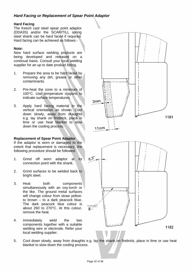
Hard Facing or Replacement of Spear Point Adaptor Hard Facing The Keech cast steel spear point adaptor (DDA3S) and/or the SCARITILL spring steel shank can be hard faced if required. Hard facing can be achieved as follows:- Note: New hard surface welding products are being developed and released on a continual basis. Consult your local welding supplier for an up to date product listing. 1. Prepare the area to be hard faced by
removing any dirt, grease or other contaminants.
2. Pre-heat the zone to a minimum of
100°C. Use temperature crayons to indicate surface temperatures.
3. Apply hard facing material in the
vertical orientation as shown. Cool down slowly, away from draughts e.g. lay shank on firebrick, place in lime or use heat blanket to slow down the cooling process.
Replacement of Spear Point Adaptor If the adaptor is worn or damaged to the extent that replacement is necessary, the following procedure should be followed. 1. Grind off worn adaptor at its
connection point with the shank. 2. Grind surfaces to be welded back to
bright steel. 3. Heat both components
simultaneously with an oxy-torch or the like. The ground metal surfaces will change colour from straw yellow-to brown – to a dark peacock blue. The dark peacock blue colour is about 260 to 270°C. At this colour, remove the heat.
4. Immediately weld the two
components together with a suitable welding wire or electrode. Refer your local welding supplier.
5. Cool down slowly, away from draughts e.g. lay the shank on firebrick, place in lime or use heat blanket to slow down the cooling process.

Page 33 of 38
Wheel Bearing Maintenance Wheel bearings should be checked at the end of each working season and adjustments made when necessary. To check and adjust wheel bearings: - 1. Raise wheels, and support, to facilitate rotation. 2. Check for endplay by pulling back and forth on wheel. 3. If bearing endplay is present, remove hubcap and cotter pin. 4. Tighten slotted nut whilst rotating wheel until resistance locks hub. 5. Back off the slotted nut one full turn. 6. Retighten until nut locks up and back off to nearest slot in nut, but no more than 30°. Note: Ensure that the bearing endplay is not apparent. Tapered roller bearings on agricultural tractor and implement wheels are generally set with a free running clearance or end play of somewhere between .03 to .18mm (.001 to .007 inches). 7. Rotate the wheel. There should be only a slight drag. 8. Replace the hubcap. 9. Grease hub via grease nipple. Be careful not to over grease as this may dislodge either the triple-
lip seal behind the inner bearing, or the hubcap. Note: When replacing bearings, care should be taken to ensure that the bearings, tools and work areas are clean. Kerosene is recommended for washing bearings, though it is not necessary to wash new bearings. Before storage or assembly of washed bearings, they must be immersed in a light mineral oil after thoroughly dry from the kerosene. Bearing cups can be pressed or driven into hub. If special drivers are not available, mild steel bars can be used (do not use hardened drifts or brass bars). Care must be taken to ensure that the cup or cone is solidly seated against the shoulders. Before fitting bearings, check condition of triple-lip seal and replace if necessary. Lightly grease seal before fitment. Ensure bearings are fully greased; i.e. grease must completely penetrate within rollers and cage to inner race.

Page 34 of 38
SWFHDF Centreframe Walking Beam Pivot Bearing Maintenance Check pivot assembly regularly for end play and adjust if necessary, using same procedure as “Wheel Bearing Maintenance” in the “General Maintenance” section. When replacing walking beam pivot bearings the following procedure should be followed: - 1. Remove the walking beam, dismantle the pivot assembly completely and wash thoroughly. 2. Remove old cups from walking beam taking care not to damage bearing seating surfaces. 3. Lightly oil the bearing housing. 4. Press the new bearing cups into the walking beam bearing housing with the use of a dolly and
ensure they are seated correctly against shoulders. 5. Grease roller surfaces of bearing cones with Mobil Special Grease. 6. With a vice fitted with soft jaws, press the bearing cone onto the bearing carrier. 7. Put the o-ring into the groove of the bearing carrier. 8. Assemble the bearing carrier subassembly into the walking beam pivot, taking care not to
damage the o-ring. 9. Check that the o-ring is not pinched. 10. Carefully tap pivot pin through the assembly until seated. Fit the washers and nut and begin to
tighten. 11. Check again that the o-ring is going into the bearing housing. 12. Ensure that un-threaded part of pivot pin never protrudes outside the bearing carrier. 13. Continue to tighten the pivot assembly whilst rotating the bearing carrier, until the resistance locks
the bearing carrier. 14. Secure pivot assembly with nyloc nut and set endplay as described previously for wheel hub. 15. Back off nut one full turn. 16. Retighten until nut locks up and back off until bearing carrier rotates. 17. Maximum back off 30°. 18. Ensure bearing adjustment is not too loose. i.e. bearing end play not apparent. 19. Rotate bearing carriers, there should only be slight drag. 20. Grease the pivot sufficiently with Mobil Special Grease, ensuring that the pivot seals are not
displaced.

Page 35 of 38
Walking Beam Pivot Bearing Maintenance (All except SWFHDF centre) Check pivot assembly regularly for end play and adjust if necessary, using same procedure as “Wheel Bearing Maintenance” in the “General Maintenance” section. When replacing walking beam pivot bearings the following procedure should be followed: - 1. Dismantle pivot assembly completely and wash thoroughly. 2. Remove old cups from walking beam taking care not to damage bearing seating surfaces. 3. Lightly oil the bearing housing. 4. Press the new bearing cups into the walking beam bearing housing with the use of a dolly and
ensure they are seated correctly against shoulders. 5. Grease roller surfaces of bearing cones with Mobil Special Grease and place into pivot housing
against cups. 6. Gently tap the bearing seals into position and check for correct alignment. 7. Tape an O-ring around outside of pivot housing on both sides. 8. DO NOT place O-rings around crankarm side-plates. 9. Position walking beam and carefully tap pivot pin through the assembly until seated. Ensure that
un-threaded part of pivot pin never protrudes outside the crankarm inner side plate. 10. Remove the tape and position O-ring seals against the crankarm inner side plates and within the
pivot housing end chamfers. 11. On the head end of the pivot pin, place the pivot lock washer, a ubolt and two nuts. 12. Tighten the nuts on the ubolt finger tight. 13. Put the remaining washer, jam nut, ubolt and nuts onto the other end of the pivot pin. 14. Fit the bolt, washers and nut and begin to tighten. 15. Continue to tighten whilst rotating the crankarm until the resistance locks the walking beam. 16. Back off nut one full turn. 17. Retighten until nut locks up and back off until the crankarm rotates. 18. Maximum back off 30°. 19. Ensure bearing adjustment is not too loose. i.e. bearing end play not apparent. 20. Rotate the walking beam, there should only be slight drag. 21. Tighten all four ubolt nuts. 22. To seat the ubolts correctly, tap the ubolts with a nylon hammer, and then retighten nuts. 23. Grease the pivot sufficiently, ensuring that the pivot seals are not displaced.
Page 36 of 38
TROUBLESHOOTING: Problem: Uneven digging depth or lack of penetration Possible Solution: Check that the frames are level both fore and aft, and across the width. Refer to “Adjustments” in
the “Operating the Scaritill” section. Check that all tyre pressures are consistent and within the limits specified in “Tyre Care” in the
“General Maintenance” section. Check that all tine assembly shank heights have been set correctly. Check that the depth control hydraulic circuit is free of air or foreign matter. Rephase the circuit as
outlined in “Purging hydraulic circuits” in the “Hydraulic System” section. Check that all hydraulic cylinder mechanical depth stops are set at the correct setting. If the ground is hard, narrower ground tools may need to be fitted. Check for worn ground tools and replace as required. Check that the angle of the ground tool is consistent across the whole implement.
Note: Sweep brands vary in profile and will perform differently, dependent on soil type and conditions. Sweeps specifically designed to penetrate hard ground are available.
Check that all tine assemblies are secured square to the toolbar i.e. the shanks should be
vertical. Adjust if necessary. Problem: Implement not tracking straight when working. Possible Solution: Check that the frames are level both fore and aft, and across the width. Refer to “Adjustments” in
the “Operating the Scaritill” section. Check that all tyre pressures are consistent and within the limits specified in “Tyre Care” in the
“General Maintenance” section. Check the tine layout to verify tines are located correctly. Check that the depth control hydraulic circuit is free of air or foreign matter i.e. rephase the circuit
as outlined in “Purging hydraulic circuits” in the “Hydraulic System” section. Check that the crankarms and walking beams are square/parallel to the frame. The implement
wheels should be in-line with the direction of travel and must not be cambered or toed in or out. Adjustments to the bearing mount plates on some models may correct this problem.
Problem: The front of the floating hitch implement is unstable, or the front castor wheels “shudder” or “wobble” when transporting. Possible Solution: Slow down to the recommended maximum transport speed of 20 km/h. Fill front castor wheels to provide ballast as per “Tyre Care” in the “General Maintenance” section. Fix castor action by engaging the transport locking pins.
Adjust load on torsion bars to place more load on castor wheels.
Page 37 of 38
Problem: Wings bouncing Possible Solution: Check that all tyre pressures are consistent and within the limits specified in “Tyre Care” in the
“General Maintenance” section. Check that the wing stabiliser wheels (if fitted) are not adjusted too high and spring compression
is set to a minimum. Problem: Hydraulic depth control not functioning properly or too slowly. Possible Solution: Check the tractor control valve and its related hydraulic system. Check that all hoses and valves are plumbed correctly. Check that the depth control hydraulic circuit is free of air or foreign matter i.e. rephase the circuit
as outlined in “Purging hydraulic circuits” in the “Hydraulic System” section. Check that sufficient oil supply is being delivered from tractor. A minimum tractor hydraulic flow
rate of 45 l/min (12 US gpm) is required.
Note: Do not allow the tractor hydraulics to supply more than 100 l/min (26 US gpm) as this may create pressure spikes & increase the pressure to operate implement.
Check for internal leaks, i.e. extend cylinders to full transport, disconnect hydraulics from tractor
and leave overnight. If any cylinder relaxes significantly, replace seals. For cylinder seal and valve replacement, refer “Cylinder Care” section.
Problem: Ground tools continue to come loose. Possible Solution: Check the condition of ground tool retaining hardware and replace as required. On chisel plow attachments, check the grade of hardware i.e. use grade 8 plow bolts with grade 8
Nyloc or conelock nuts and tighten to recommended assembly torque. Refer to “Standard Bolt Head Markings And Torque Specifications”
Problem: Tine component or groundtool breaking Possible Solution: Change to a groundtool that the tip of the groundtool is rearward of the tine pivot. This will
improve tine jump height.
Work at a shallower depth.
Refrain from working in areas with significant rocks or rock reefs. Disclaimer Trailed wheeled, soil engaging equipment by nature cannot be assured of tracking straight as the machine will always take the least line of resistance. Some factors which can influence the machine from tracking straight include: working on sides of hills, uneven and non-homogeneous ground surfaces (due to topography & history of tillage/other practices), unsymmetrical forces from ground engaging attachments, machine design and combinations of trailing equipment. Whilst every effort has been made to ensure our equipment tracks straight, additional assistance may be required in the form of GPS-controlled wheel or hitch steering to gain more stable tracking.

Page 38 of 38
OHS COMPLIANCE NOTIFICATION FORM
Company Name A.F. GASON PTY LTD
A hazard identification, risk assessment and risk control procedure has been carried out on a representative example of the under
mentioned product(s) in accordance with the Occupational Health and Safety requirements of all states and territories of Australia and where
found necessary the appropriate risk control measures have been incorporated in the product specifications.
The operator’s manual contains the necessary health and safety information and safety warnings are applied to the product where necessary.
Product Description SCARITILL / HYDRATILL WIDE 5-SECTION SCARITILL / HYDRATILL
Models No. or No.’s SWFHDF / HWFHDF ALL MODELS EXCLUDING CT2 and WIDE 5-SECTION
Signed on behalf of the above named company
Name (printed) GREG GASON GREG GASON
Position TECHNICAL SERVICES MANAGER TECHNICAL SERVICES MANAGER Date 15/09/2005 05/10/2005
Details of the Unit Assessed for the Purpose of Compliance
Model No. HWFHDF 57-337 SNFH 49-250
Serial No. 1002 1198
Date of Inspection 15/09/05 15/10/05
Location of Inspection ARARAT, VICTORIA ARARAT, VICTORIA