Scanning and digitizing the SA Agulhas II - EE Publishers · The S.A. Agulhas II was docked at the...
19
Scanning and digitizing the SA Agulhas II by Dr Annie Bekker, Stellenbosch University 1
Scanning and digitizing the SA Agulhas II - EE Publishers · The S.A. Agulhas II was docked at the Simon’s Town Naval Base in early March this year. This massive effort was managed
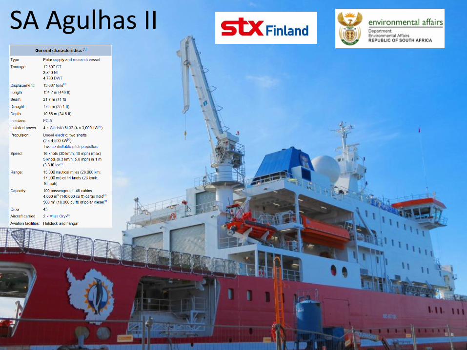
• 1 Voyage in Baltic ocean (2012) • 4 Voyages to Antarctica (2012 to 2016) • 2 Voyages to Marion Island
State-of the art in ice-going ship design
• Ships are designed using computer simulation models and ice tank tests. • SPARSE public domain full-scale ship data.
4
Presenter
Presentation Notes
You could mention the current lab testing her in Germany, the Polarstern work, and ice tank testing which all fit into the puzzle of attainting the overarching research goal.
Full-scale measurement consortium
Ship drive train design
and operation
5
Ship building, design and operation
Structural ice loading on the
hull – strain measurements
Measurement of ice
conditions
Measurement of ice
properties
Noise and vibration data
Environmental and weather
conditions
Project aim
• To create and improve a scientific basis for the design of ice-going ships
• Establish a solid connection between ice properties / conditions and ice load from the hull and propulsion shafting and structural vibration and human comfort.
6
Instrumentation and measurement model
7
44 channels of acceleration measurements
Dry Dock at Simon’s Town Naval Base
8
Presenter
Presentation Notes
The S.A. Agulhas II was docked at the Simon’s Town Naval Base in early March this year. This massive effort was managed by African Marine Services (AMSOL) under the coordination of Robert Hales. After five years of hard work, the ship needed a new coat of paint, buffing of her propellers and replacement of the anodes that keep her from rusting. This is also the opportunity to check the hull for damage and service rotating equipment, such as the propellers, bow- and stern thrusters. Dry-docking of the vessel provided the opportunity to directly capture and digitize the hull and propeller geometry. The “reverse engineering” of the ship seemed a challenging task, until the Sound and Vibration Research Group (SVRG) at Stellenbosch University were placed in contact with Brent Godfrey from Optron (Pty.) Ltd. and Ian Thomson from Cape Survey.
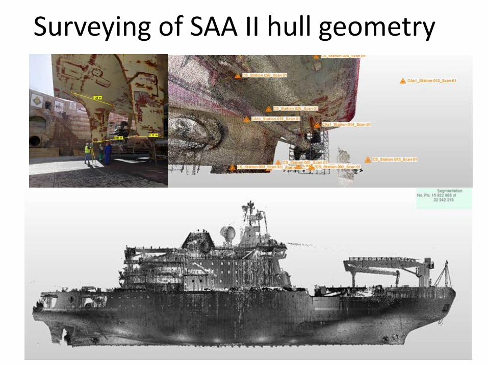
Surveying of SAA II hull geometry
9
10
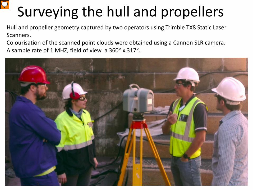
Hull and propeller geometry captured by two operators using Trimble TX8 Static Laser Scanners. Colourisation of the scanned point clouds were obtained using a Cannon SLR camera. A sample rate of 1 MHZ, field of view a 360° x 317°.
Surveying the hull and propellers
Presenter
Presentation Notes
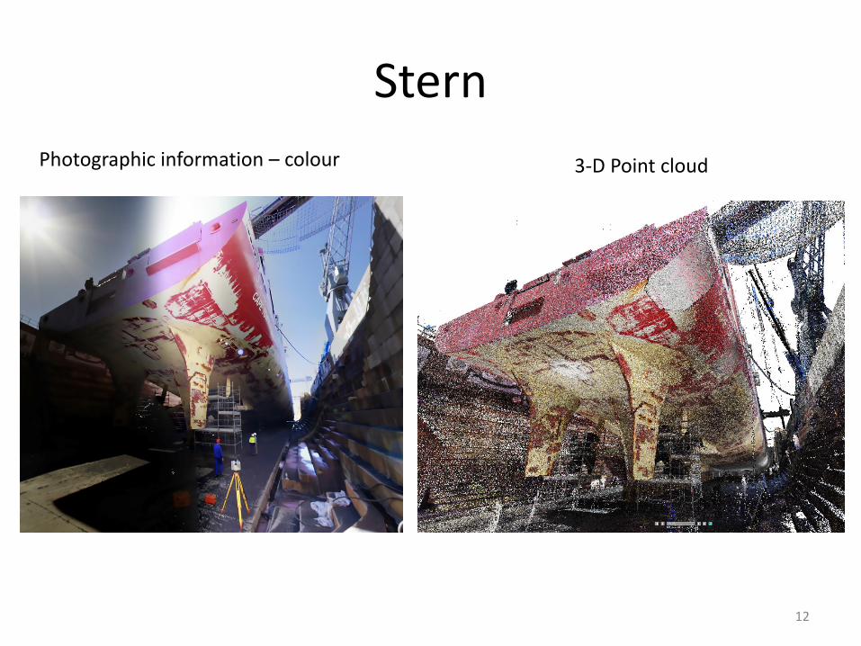
The geometry of the S.A. Agulhas II was captured using two Trimble TX8 Static Laser Scanners. They also used a Cannon SLR camera for the colourisation of the scanned point clouds. The scanners sample at a rate of 1 MHz, covering a 360° x 317° field, only a 43° cone around the supporting tripod is not captured. Figure 3 presents a photographic image with the corresponding point cloud from a station at the stern. The scanners were placed progressively along the port and starboard flanks of the vessel. The exact locations of the scanners were not important, as long as the scan data from a particular station overlapped with the one before it. Space around the ship was tight in the dry dock and the team had to insure the incidence angle of the scanner on the geometry was not too large. As the scanner relies on line of sight, areas with more complex geometry were scanned multiple times from various angles.
11
Presenter
Presentation Notes
Once scanning along the side of the hull was complete, further scans were conducted from higher vantage points. These included scans taken from the edge of the dry dock (Figure 4), to scans taken on board the ship in various locations. The geometry of the propeller blades was also captured in high detail for the purposes of structural dynamic analysis on the blades. The gale-force South Easterly wind interrupted sandblasting operations on the hull, which allowed the team to complete the surveying in 57 scans of the expansive structure in only three hours.
Stern
12
Photographic information – colour 3-D Point cloud
Propeller
13
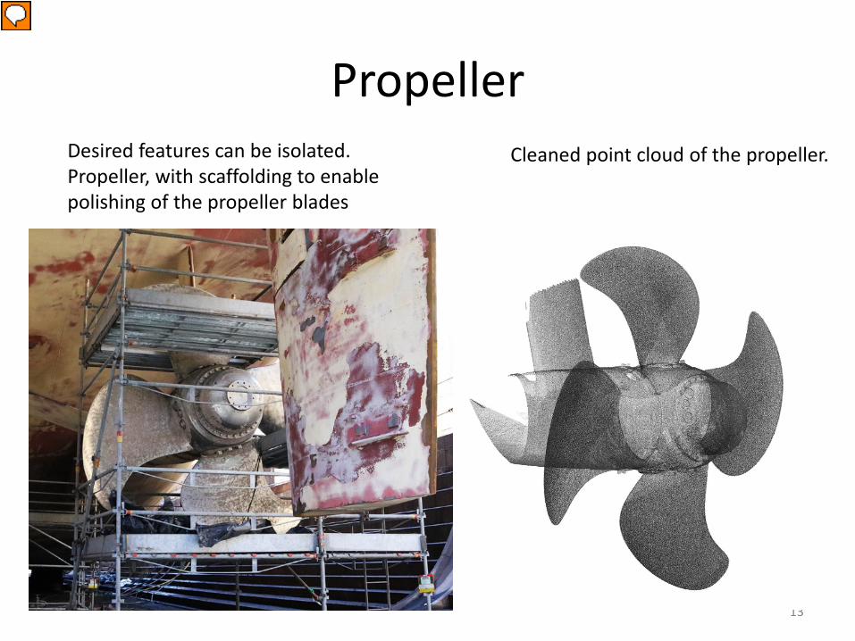
Desired features can be isolated. Propeller, with scaffolding to enable polishing of the propeller blades
Cleaned point cloud of the propeller.
Presenter
Presentation Notes
Laser surveying is convenient in that the desired features can be isolated effectively to provide only the desired features. Working with Trimble Realworks software allows is easy and does not require extensive training.
14
Presenter
Presentation Notes
The entirety of the vessel was captured in about 6 hours. A conclusion from this is that surveying technology can effortlessly capture large objects in human surroundings and digitize the geometry and photographic colour.
Extraction of the hull geometry
Laser surveying
in dry dock
Cleaning of Point Cloud
Extraction of hull
contours
Generate hull
surface
Presenter
Presentation Notes
Post processing of the 3-D point cloud and photographic information is performed in Trimble RealWorks v10.3. The individual scans are combined through a process known as plane based registration where common geometric features are used to overlap scans from different stations. The scans include both the geometry of the vessel as well as the surrounding environment. Figure 5 shows a representation of the registered point cloud, with colourized overlay for the entire vessel. The colourization clearly shows the sections of the ship where sandblasting and painting of the under-coat had commenced. The shadows of the dock-side cranes are also visible. Next, the ship geometry is isolated by cleaning away the surrounding environment using the RealWorks editing tools. The edited point cloud can then be meshed to create a surface geometry of the desired sections of the ship.