Embed Size (px)
Citation preview

Scanning Acoustic MicroscopesKSI - Kraemer Sonic Industries
www.ksi-germany.de

KSI - Kraemer Sonic Industries
Welcome to KSI - Kraemer Sonic Industries and the world of scanning acoustic microscopy
Kraemer Sonic Industries (KSI) provides the next generation of scan-ning acoustic microscopes (SAM). Designed and developed by an ambitious team of engineers and application-specialists and with ex-��������������� ���������������� ������������������������������presents you the new scanning acoustic microscope: KSI v-Series.
With the help of scanning acoustic microscopes voids, delamina-tions, bubbles as well as changes of mechanical properties inside specimen can be detected without any damage or changes down to a minimum size of 0,3 μm. Scanning acoustic microscopy is a powerful tool to inspect, detect and valuate. With the products of KSI devel-opment-, product- and quality-control becomes easy and effective.
The products of KSI sound your sample and lend you an ear, as they are the “antenna“ you need to see the mechanical properties of your specimen.
We create the SAM-future.

KSI - Kraemer Sonic Industries
The headquater of Kraemer Sonic Industries (KSI) is located in Herborn/Germany with sales agents all over the globe.
Together with our partner the “Institut für Akustomikroskopie“ and the long experience of our employees and the president of KSI - Dr. Klaus Kraemer - we develop, produce and distribute new solu-tions and applications for scanning acoustic microscopes, as well as special ultrasonic solutions. The goal of all efforts of KSI - Krae-mer Sonic Industries is to provide products of highest quality and ������������������������������ ����������������������������-vidual solutions for ultrasonic inspection. The history of scanning acoustic microscopy and the experince of KSI go back to 1989.
Headquater Herborn / GermanyEurope
Asia
USA
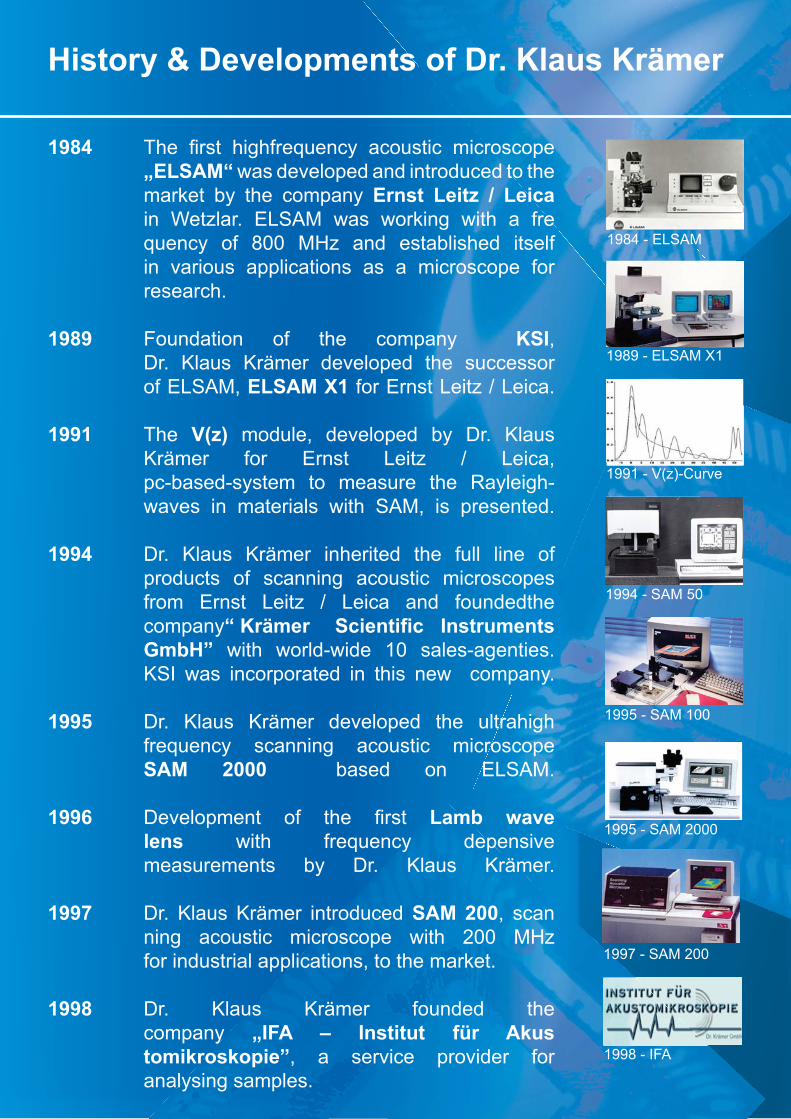
History & Developments of Dr. Klaus Krämer
1984 � �� ����� �� ��������� �������� �������� „ELSAM“ was developed and introduced to the
market by the company Ernst Leitz / Leica in Wetzlar. ELSAM was working with a fre quency of 800 MHz and established itself in various applications as a microscope for research.
1989 Foundation of the company KSI, Dr. Klaus Krämer developed the successor of ELSAM, ELSAM X1 for Ernst Leitz / Leica.
1991 The V(z) module, developed by Dr. Klaus Krämer for Ernst Leitz / Leica, pc-based-system to measure the Rayleigh- waves in materials with SAM, is presented.
1994 Dr. Klaus Krämer inherited the full line of products of scanning acoustic microscopes from Ernst Leitz / Leica and foundedthe company���������� ��� ��� ��� ����� �� GmbH” with world-wide 10 sales-agenties. KSI was incorporated in this new company.
1995 Dr. Klaus Krämer developed the ultrahigh frequency scanning acoustic microscope SAM 2000 based on ELSAM.
1996�� ��!�������� � � �� ����� Lamb wave lens with frequency depensive measurements by Dr. Klaus Krämer.
1997 Dr. Klaus Krämer introduced SAM 200, scan ning acoustic microscope with 200 MHz for industrial applications, to the market.
1998 Dr. Klaus Krämer founded the company „IFA – Institut für Akus tomikroskopie”, a service provider for analysing samples.
1984 - ELSAM
1989 - ELSAM X1
1991 - V(z)-Curve
1994 - SAM 50
1995 - SAM 100
1995 - SAM 2000
1997 - SAM 200
1998 - IFA

History & Developments of Dr. Klaus Krämer
2000 Dr. Klaus Krämer introduced WINSAM Vario I-III scanning acoustic microscope series for research and quality control with frequencies up to 400 MHz.
2002 Air support linear motion scanner for SAM, industrial applications, maintanance free, was introduced to the market by Dr. Klaus Krämer.
2003 Dr. Klaus Krämer founded the distribution company SAMTEC – Scanning Acoustic Microscopy Technology in Aalen.
2004 Dr. Klaus Krämer developed and introduced the Evolution series I-III. SAM with 500 MHz bandwidth.
2005 Dr. Klaus Krämer presented the Wafer-Handler for SAM Evolution series.
2006 Dr. Klaus Krämer presented the Twin-system and the Auto-Ingot.
2007 Dr. Klaus Krämer presented the Auto-Tray-Handler for SAM. � � ��"���� ���������� ������������ #�$% and SAMTEC GmbH are sold to PVA TePla AG. The subsidiary is named PVA TePla Analytical Systems GmbH
2009 Dr. Klaus Krämer founded the company KSI - Kraemer Sonic Industries GmbH with
� � � �� ����������� ���� ��� %��$��� &#������'��
Dr. Klaus Krämer introduced the new KSI v-Series with the products v-200, v-400, v-700, v-1000, v-duo, v-quattro and v-octo.
2000 - WINSAM Vario III
2002 - Air support scanner
2004 - Evolution III
2005 - Wafer-Handler
2006 - Auto-Ingot
2006 - Twin-system
2007 - Auto-Tray-Handler
Operation principle
To produce a complete image of a sample the acoustic objective scans the sample line by line. A transducer with good focusing on axis can be used for both transmitting and receiving the signal. The image is formed by scanning the transducer mechanically over the sample. The time needed to produce a complete image of the sample depends on the size of the sample and the selected image resolution. In general it is pos-sible to create an ultrasonic picture of a small sample in a few seconds.
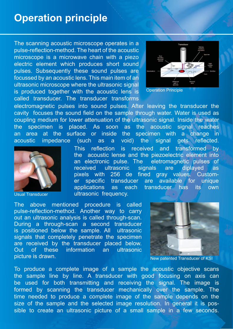
Operation Principle
Usual Transducer
New patented Transducer of KSI
The scanning acoustic microscope operates in a �����*��+�����*��� ���� �� ������� ����������microscope is a microwave chain with a piezo electric element which produces short sound pulses. Subsequently these sound pulses are focussed by an acoustic lens. This main item of an ultrasonic microscope where the ultrasonic signal is produced together with the acoustic lens is called transducer. The transducer transforms electromagnetic pulses into sound pulses. After leaving the transducer the ��!���� � ������� ��������������� ���������� ��� ��������;����� �����������coupling medium for lower attenuation of the ultrasonic signal. Inside the water the specimen is placed. As soon as the acoustic signal reaches an area at the surface or inside the specimen with a change in �������� ���������� &��� � ��� �� !��'� � �� ������� ����� ��+�������
� ��� ��+������ ��� �����!��� ���� ���������� $��the acoustic lense and the piezoelectric element into an electronic pulse. The eletromagnetic pulses ofreceived ultrasonic signals are diplayed as ��<���� ��� � �=>� ��� ����� ����� !������� ?����-��� �������� ����������� ���� �!����$��� �� ������applications as each transducer has its own ultrasonic frequency.
The above mentioned procedure is called �����*��+�����*��� ��� @�� ��� ���� �� ������out an ultrasonic analysis is called through-scan. During a through-scan a second transducer is positioned below the sample. All ultrasonicsignals that completely penetrate the specimen are received by the transducer placed below. Out of these information an ultrasonic picture is drawn.
Operation principle
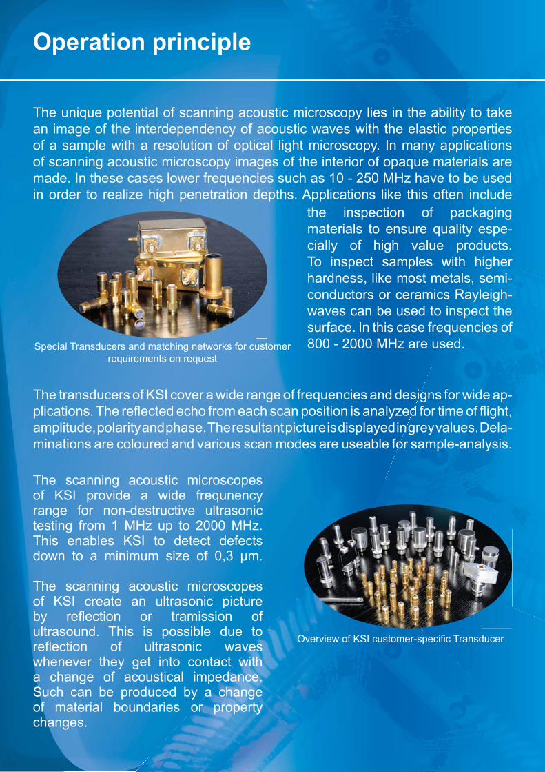
Special Transducers and matching networks for customerrequirements on request
B!��!����������������*������������������
The unique potential of scanning acoustic microscopy lies in the ability to take an image of the interdependency of acoustic waves with the elastic properties of a sample with a resolution of optical light microscopy. In many applications of scanning acoustic microscopy images of the interior of opaque materials are made. In these cases lower frequencies such as 10 - 250 MHz have to be used in order to realize high penetration depths. Applications like this often include
the inspection of packagingmaterials to ensure quality espe-cially of high value products.To inspect samples with higher hardness, like most metals, semi-conductors or ceramics Rayleigh-waves can be used to inspect the surface. In this case frequencies of800 - 2000 MHz are used.
The scanning acoustic microscopes of KSI provide a wide frequnency range for non-destructive ultrasonic testing from 1 MHz up to 2000 MHz.This enables KSI to detect defects down to a minimum size of 0,3 μm.
The scanning acoustic microscopesof KSI create an ultrasonic picture $�� ��+������ �� ���������� �ultrasound. This is possible due to ��+������ � ���������� ��!���whenever they get into contact with a change of acoustical impedance. Such can be produced by a changeof material boundaries or propertychanges.
The transducers of KSI cover a wide range of frequencies and designs for wide ap-������������ ����+�������� ������� ���������������������J�����������+�� �Q�amplitude, polarity and phase. The resultant picture is displayed in grey values. Dela-minations are coloured and various scan modes are useable for sample-analysis.
Transducer
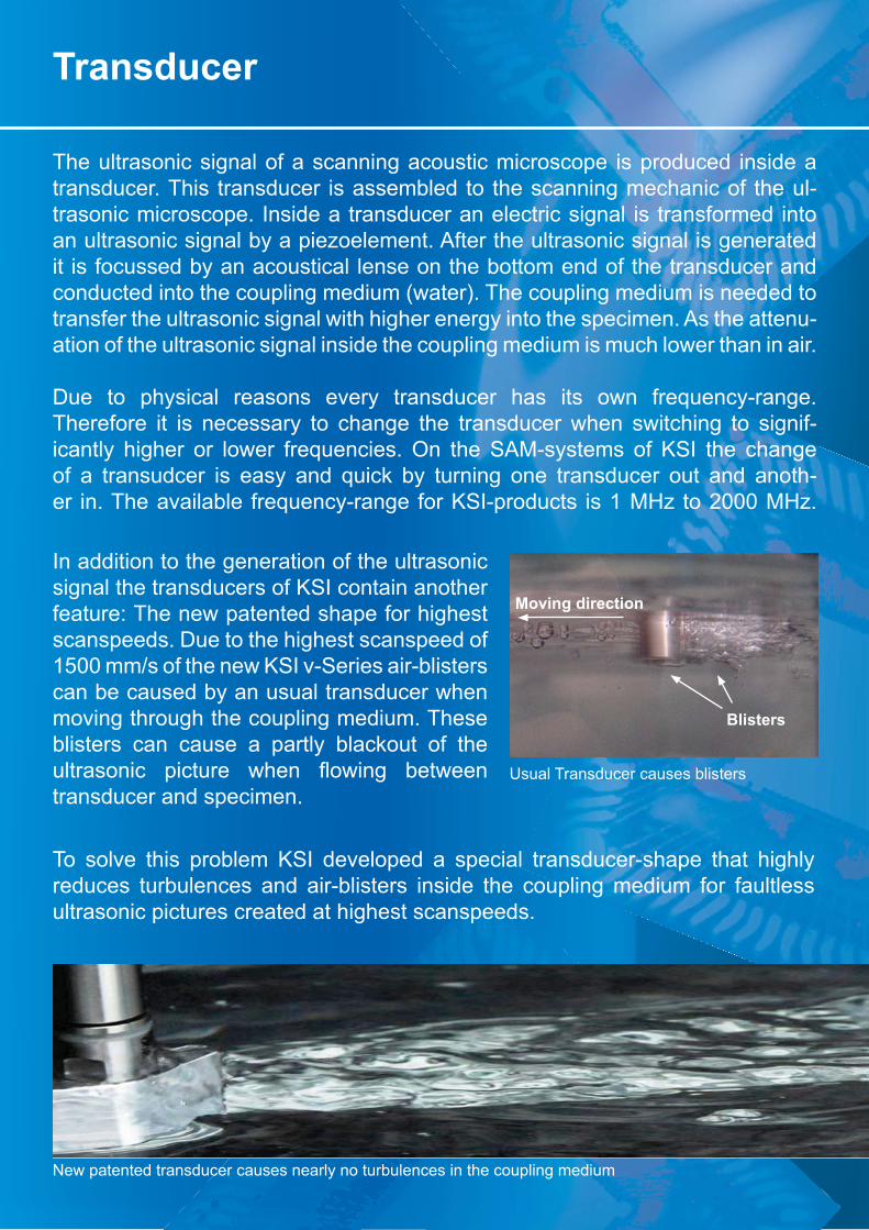
Moving direction
Blisters
The ultrasonic signal of a scanning acoustic microscope is produced inside a transducer. This transducer is assembled to the scanning mechanic of the ul-trasonic microscope. Inside a transducer an electric signal is transformed into an ultrasonic signal by a piezoelement. After the ultrasonic signal is generated it is focussed by an acoustical lense on the bottom end of the transducer and conducted into the coupling medium (water). The coupling medium is needed to transfer the ultrasonic signal with higher energy into the specimen. As the attenu-ation of the ultrasonic signal inside the coupling medium is much lower than in air.
Due to physical reasons every transducer has its own frequency-range. Therefore it is necessary to change the transducer when switching to signif-icantly higher or lower frequencies. On the SAM-systems of KSI the change of a transudcer is easy and quick by turning one transducer out and anoth-er in. The available frequency-range for KSI-products is 1 MHz to 2000 MHz.
In addition to the generation of the ultrasonic signal the transducers of KSI contain another feature: The new patented shape for highest scanspeeds. Due to the highest scanspeed of 1500 mm/s of the new KSI v-Series air-blisters can be caused by an usual transducer when moving through the coupling medium. These blisters can cause a partly blackout of the ���������� �������� � ��� +����� $������transducer and specimen.
Usual Transducer causes blisters
To solve this problem KSI developed a special transducer-shape that highlyreduces turbulences and air-blisters inside the coupling medium for faultless ultrasonic pictures created at highest scanspeeds.
New patented transducer causes nearly no turbulences in the coupling medium

Scanmodes
A-Scan
Transducer with specimen
Specimen
With scanning acoustic microscopes the whole volume of a sample can be penetrated and inspected without any change or damage. To get all information needed and a detailed understanding of the inspect-ed sample, different scanmodes are used. The following pictures ���� �<������� �<������ � �� ��������� ���� � ���� �������� ��!��������
A-Scan
Amplitude-Scan, one-dimensional. The information is contained in the ���� � �� �������� ��!�� ��� ��+��*ted from the specimen. This time of +�� �� ��������� ��� ���������� ����the depths of the sample feature. A digital waveform on the user inter-face screen displays the arriving echoes. This quantitative time distance measurement (echo-time) display is used to set electronic gates to select the depth range of view. If more than one gate is placedmultiple images are displayed on the monitor screen.

Scanmodes
B - Scan mode and its application
Brightness-Scan, two-di-mensional. The scanner is moving in x-direction to get a cross section im-age in x-direction. The depth of different struc-tures can be measured.
C - Scan mode and its application
C-Scan (x-, y-Scan) moves the scanner in a meander pattern over the sample, depending on the set of in-strument parameters. The image is composed line by line.
D - Scan mode and its application
D-Scan (Diagonal-Scan) is a combination of the B-Scan and C-Scan func-tions. A meander scan is carried out and the po-sition of the gate is al-tered at the same time. The resulting image rep-resents a diagonal sec-tion through the sample.
B-Scan B-Scan image of an integrated circuit (IC)
C-Scan C-Scan image of an IC
D-Scan D-Scan image of an IC

Scanmodes
G-Scan G-Scan image of an IC
P-scan P-Scan image of an IC
TT-Scan TT-Scan image of an IC
G - Scan mode and its application
G-Scan (Gate-Scan) pro-duces multiple images depending on the „gate memory“. Different set-tings can be stored for automatic evaluation.
P - Scan mode and its application
P-Scan - Cascade dis-play of parallel arrays of cross section plans from top to bottom, the slic-es are selectable freely.
TT - Scan mode and its application
TT-Scan (transmission) stands for Through-Scan. The transducer above the samples emits an ultra-sonic signal that is detect-ed by a second transduc-er placed at the bottom. This image mode provides lower resolution, but a faster information about volume-defects due to the second transducer at the bottom of the sample.

Scanmodes
Tray - Scan mode and its application
This scan is a special mode for the analysis of IC-samples that are mounted to a JEDEC-tray.
W - Scan mode and its application
W-Scan stands for Wafer-Scan and is a combination of a G-Scan and a Tray-Scan adapted to wafers. This application comes with �� �������*�������� ���-ple stage, automatic image analysing software and special scanning software.
S - Scan mode and its application
S-Scan stands for simul-taneous-scan. During one scan a C-Scan and a TT-Scan is carried out to reduce scantime.
Tray-Scan Tray-Scan image
W-Scan W-Scan image
C-Scan image of an IC TT-Scan image of an IC
Scanmodes
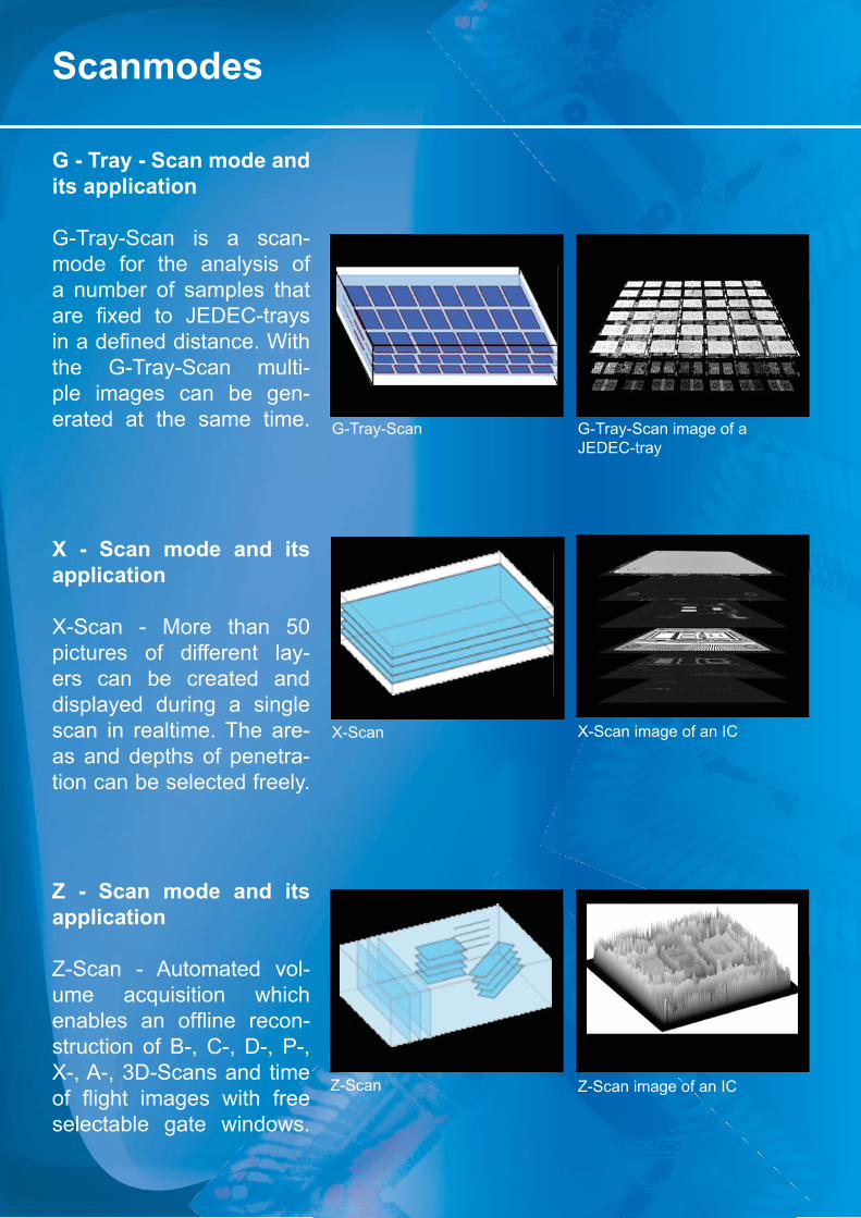
G - Tray - Scan mode andits application
G-Tray-Scan is a scan-mode for the analysis of a number of samples that ���� �<��� �� [\�\?*����������������������������;�� �the G-Tray-Scan multi-ple images can be gen-erated at the same time.
X - Scan mode and its application
X-Scan - More than 50 pictures of different lay-ers can be created and displayed during a single scan in realtime. The are-as and depths of penetra-tion can be selected freely.
Z - Scan mode and its application
Z-Scan - Automated vol-ume acquisition which ���$���� ��� +���� ����-struction of B-, C-, D-, P-, X-, A-, 3D-Scans and time � +�� �� ������� ��� � ����selectable gate windows.
G-Tray-Scan G-Tray-Scan image of a JEDEC-tray
X-Scan X-Scan image of an IC
Z-Scan Z-Scan image of an IC

Scanning Acoustic Microscopes
KSI v-SeriesTM
The KSI v-Series is a new generation of scanning acoustic microscopes. Combined with a new developed scanning mechanic and the new pat-ented transducer shape highest scanspeeds are reached. This reduces the time of inspection by 30% compared to other SAM-systems. The in-spection of large samples is realized by big-sized scanning-areas. All fea-tures of the new KSI v-Series are realized at best price-perfomance ratio.
Key features of the new KSI v-Series:
- Highest scanspeed 2000 mm/s- Reduction of scantime by 30% compared to other systems- New patented transducershape- High quality imaging- One, two, four or eight transducers for highest throughput*�_��������������������`��<�����`�*�_�<��������������{�������<�|�����}- Bandwith up to 550 MHz*�_�<����������������~�>�=<- Flexible application through different scan modes- Simple operation with Windows 7 graphical user interface- Excellent price-performance ratio
KSI v-200TM
Designed for inspection of small samples in labs and research
*�_�<�������������~��������<�{=�����*�_�<����������������~�{�=<�- Bandwidth: 100 MHz - 15 MHz & 30 MHz Transducer included - Very compact desktop unit at best price

Scanning Acoustic Microscopes
KSI v-400TM
Designed for the use in labs, research and production
- Maximum Scanning Speed: 2000 mm/s - 30 % faster image-display than comparable systems *�_�<�������������~��������<��������*�_���������������~�����`��<�����`��- Bandwidth: 550 MHz *�_�<����������������~�>�=<�- New transducers (patented)
KSI v-700TM
Designed for the inspection of large samples in labs, research and production
- Maximum Scanning Speed: 2000 mm/s - 30 % faster image-display than comparable system� � � � � � *�_�<�������������~�|������<�>������� � � � � � *�_���������������~�����`��<�����`�� - Bandwidth: 550 MHz � � � � � � *�_�<����������������~�>�=<� - New transducers (patented)
KSI v-1000TM
Designed for the inspection of very large samples in research and production
- Maximum Scanning Speed: 2000 mm/s - 30 % faster image-display than comparable systems*�_�<�������������~�{�������<�|��}����*�_���������������~�����`��<�����`��- Bandwidth: 550 MHz *�_�<����������������~��=�<- New transducers (patented)
Scanning Acoustic Microscopes
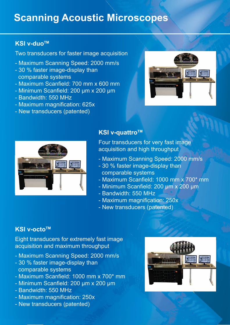
KSI v-duoTM
Two transducers for faster image acquisition
- Maximum Scanning Speed: 2000 mm/s - 30 % faster image-display than comparable systems *�_�<�������������~�|������<�>������*�_���������������~�����`��<�����`��- Bandwidth: 550 MHz *�_�<����������������~�>�=<�- New transducers (patented)
KSI v-quattroTM
Four transducers for very fast image acquisition and high throughput
- Maximum Scanning Speed: 2000 mm/s - 30 % faster image-display than comparable systems � � � � � � *�_�<�������������~�{�������<�|��}����� � � � � � *�_���������������~�����`��<�����`�� - Bandwidth: 550 MHz � � � � � � *�_�<����������������~��=�<� - New transducers (patented)
KSI v-octoTM
Eight transducers for extremely fast image acquisition and maximum throughput
- Maximum Scanning Speed: 2000 mm/s - 30 % faster image-display than comparable systems *�_�<�������������~�{�������<�|��}����*�_���������������~�����`��<�����`��- Bandwidth: 550 MHz *�_�<����������������~��=�<�- New transducers (patented)
Scanning Acoustic Microscopes
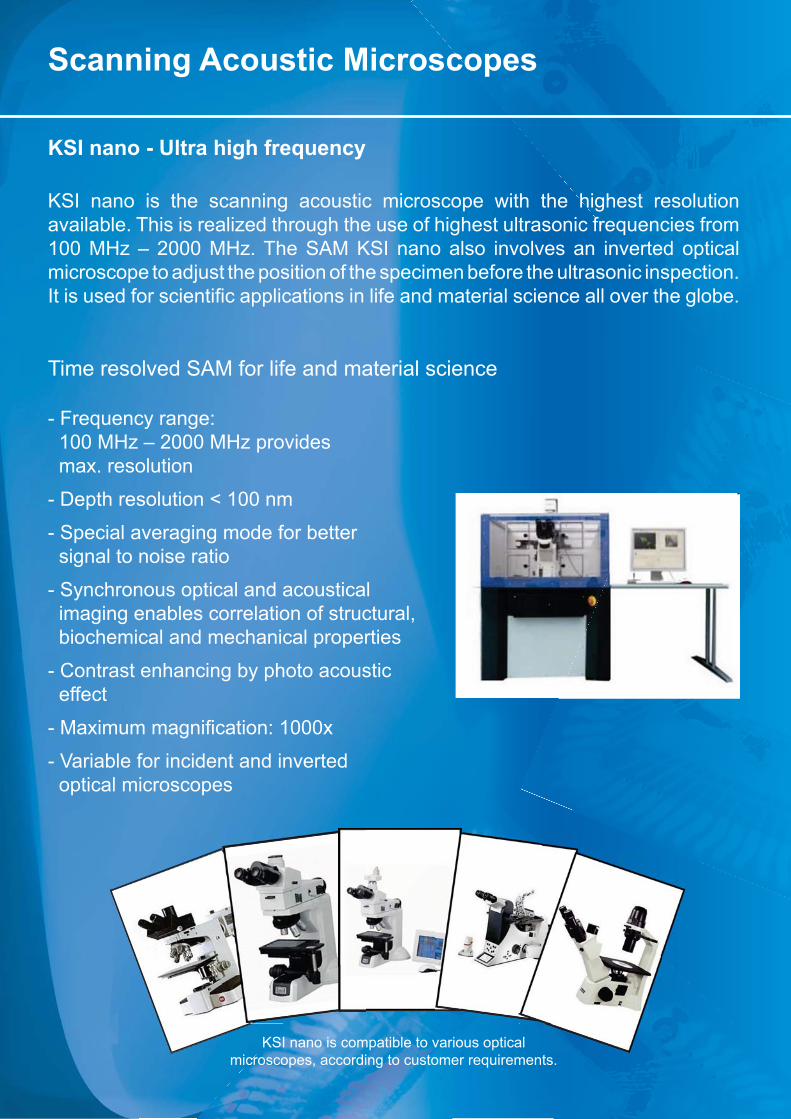
KSI nano - Ultra high frequency
KSI nano is the scanning acoustic microscope with the highest resolution available. This is realized through the use of highest ultrasonic frequencies from 100 MHz – 2000 MHz. The SAM KSI nano also involves an inverted optical microscope to adjust the position of the specimen before the ultrasonic inspection. �������������������������������������������������������������������!���� ����$��
Time resolved SAM for life and material science
- Frequency range: 100 MHz – 2000 MHz provides max. resolution
- Depth resolution < 100 nm
- Special averaging mode for better signal to noise ratio
- Synchronous optical and acoustical imaging enables correlation of structural, biochemical and mechanical properties
- Contrast enhancing by photo acoustic effect
*�_�<����������������~�{���<�
- Variable for incident and inverted optical microscopes
KSI nano is compatible to various opticalmicroscopes, according to customer requirements.
��� ��������� ����
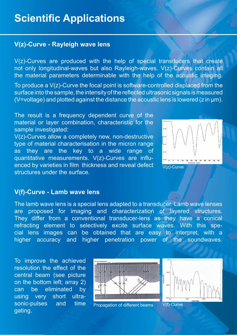
V(z)-Curve - Rayleigh wave lens
V(z)-Curves are produced with the help of special transducers that create not only longitudinal-waves but also Rayleigh-waves. V(z)-Curves contain all the material parameters determinable with the help of the acoustic imaging.
To produce a V(z)-Curve the focal point is software-controlled displaced from the ������������ ��������Q�� �������������� ����+������������������������������������(V=voltage) and plotted against the distance the acoustic lens is lowered (z in μm).
V(z)-Curve
V(f)-CurvePropagation of different beams
The result is a frequency dependent curve of the material or layer combination, characteristic for the sample investigated: V(z)-Curves allow a completely new, non-destructivetype of material characterisation in the micron rangeas they are the key to a wide range of ����������!�� �������������� �&J'*?��!��� ���� ��+�-������$��!������������������ ��������������!����������structures under the surface.
V(f)-Curve - Lamb wave lens
The lamb wave lens is a special lens adapted to a transducer. Lamb wave lenses are proposed for imaging and characterization of layered structures. They differ from a conventional transducer-lens as they have a conical refracting element to selectively excite surface waves. With this spe-cial lens images can be obtained that are easy to interpret, with a higher accuracy and higher penetration power of the soundwaves.
To improve the achieved resolution the effect of the central beam (see picture on the bottom left; array 2)can be eliminated by using very short ultra-sonic-pulses and time gating.

Automatisation and industrial systems
These features include robust industrial mechanical designs, closed dual loop positioning servo systems, multichannel and data acquisition.The KSI i-Series includes the following systems:
- KSI i-WaferTM
- KSI i-IngotTM
- KSI i-AirTM
- KSI i-XLTM
KSI i-SeriesTM
The KSI i-series is a new generation of ultra-sonic inspection systems designed and adapted for the inspection of wafers, ingots, very large or hydrophobic samples. The mechanical systems of � �� ���� �*������� ��+���� �$���� ����������� ���� ������-ductor factory designs that incorporate features cos-���J��� �� � �� �������!������ � ��� �������� ���������
The systems of the KSI i-Series incorporate a number of featuresthat have been developed with the experience of over 30 years in ultrasonic in-strumentation and sys-tem design together with our co-operation partners.
Hydrophobic Samples
Semiconductor InspectionKSI i-XL

Automatisation and industrial systems
KSI i-WaferTM
Automated wafer bond inspection. Together with the new developed scanning mechanic of the KSI v-Series and the new patented transducer shape high-est scanspeeds are reached. Combined with a customized manual wafer car-tridge or an automated wafer-handler the time of inspection is reduced up to 30% compared to other SAM-systems. The KSI i-wafer is an advanced in-strument which automatically handles and inspects wafers on operator-se-lected accept/reject criteria. With the help of the KSI i-Wafer voids, delami-antions or inclusions inside wafers and its structures can be detected. The inspection of multiple wafers up to a size of 450 mm is already applicable.
Key features of the new KSI i-Wafer:
- Highest scanspeed 1500 mm/s- New patented transducershape- High quality imaging- One, two or four transducers for highest throughput- Defects of just a few microns are detectable- Inspection of 200 mm, 300 mm, 450 mm wafers- Frequency range from 10 MHz to 550 MHz*�_�<�����������������>�=<�- Flexible application through different scan modes- Simple operation with Windows 7 graphical user interface- KSI Vision SoftwareTM
- Application to customer-needs- Excellent price-performance ratio
Positioning for manual-wafer cartrige with cus-tomized wafer holder
Automated 200 + 300 mm wafer-handler with magazine for wafers, roboter arms, aligner and bar code reader

KSI i-IngotTM
The new KSI i-Ingot is a special application for the nondestructive volume-in-spection of crystal-ingots. Based on a new patent the fast detection of voids or inclusions inside ingots becomes possible. Various ingot-sizes up to 450 mm are already applicable in a shortened inspection time and without extensive set-up requirements. In addition the new inspection process is rugged against external ��+��������;�� �� �����������*�����!�������������������*��J���{���`��can be detected with up to 8 channel transducer system for very high throughput.
Key features of the new KSI i-Ingot:
- New mechanic for fast set-up (patent pending)- Multi-transducer system up to 8 channels- Very fast inspection and image aquisition- Industrial standart*����$���������Q������������������������+������- Inspection of various ingot-sizes, quick set-up- Ingot sizes up to 450 mm, applicable- Ready for 24h operation- Customized systems available
Automatisation and industrial systems
Si-Ingots KSI i-Ingot with water tank for ingots up to 2000 mm length
Ingot holder and rotation system
New patent based ultrasonic inspection system
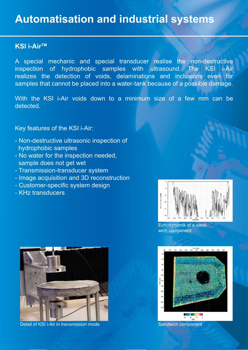
KSI i-AirTM
A special mechanic and special transducer realise the non-destructive inspection of hydrophobic samples with ultrasound. The KSI i-Air realizes the detection of voids, delaminations and inclusions even for samples that cannot be placed into a water-tank because of a possible damage.
With the KSI i-Air voids down to a minimum size of a few mm can be detected.
Key features of the KSI i-Air:
- Non-destructive ultrasonic inspection of hydrophobic samples- No water for the inspection needed, sample does not get wet- Transmission-transducer system- Image acquisition and 3D reconstruction*�?������*���������������������- KHz transducers
Automatisation and industrial systems
Echodynamik of a sand-wich component
Sandwich componentDetail of KSI i-Air in transmission mode

Automatisation and industrial systems
KSI i-XLTM
A special mechanic and special sample stage combined with new transducers realise the non-destructive inspection of very large samples up to 8 m x 4 m x 4 m. Especially designed for the inspection of airfoil of planes this ultrason-ic inspection can be used for large samples or even already assembled parts.Together with our co-operation partner immersion scanners in a number of different shapes and sizes are available. All are analyzed by advanced ���� ������ ������ �������� �������� �������� _�� ������� ����������� ���� ��-semblies are designed using 3D modeling software creating the most rigid and versatile mechanical structures available. In combination with „pulse-on-position“ technique it ensures full inspection coverage over the geom-����� $����� �� � �� ����� ��������� ����� �������Q� ����������� � ����� ������
Key features of the KSI i-XL:
- Non-destructive ultrasonic inspection of samples up to 8 m x 4 m x 4 m- Special mechanic and sample stage, customized- New transducers with waterfall-mechanism- Multi-transducer system up to 8 channels - Application to customer needs
Special transducer-design with waterfall-mechanism
Inspection of specimen up to 8 m x 4 m x 4 m
Inspection of an airplane-wing

Applications
Optical Image Transducer Acoustic image
Bonded and soldered structures
Detection of delaminationsin packages
Contacts castings
Applications
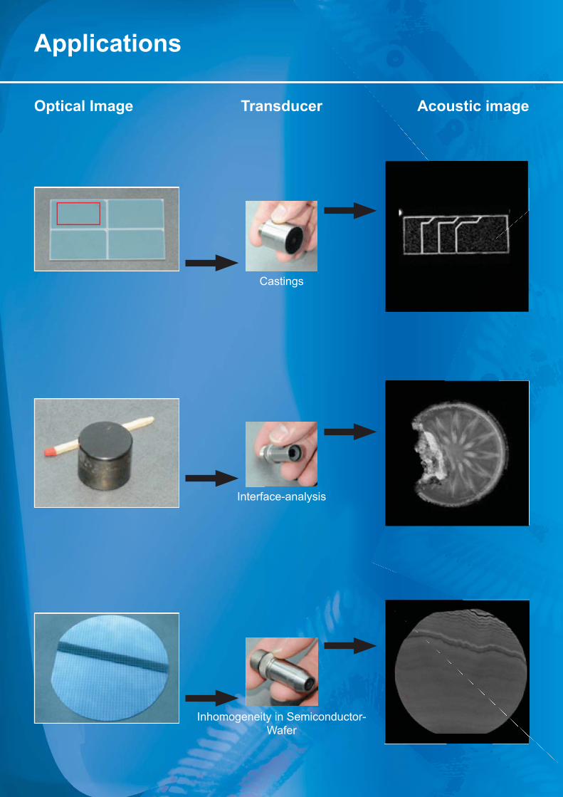
Acoustic imageOptical Image Transducer
Castings
Interface-analysis
Inhomogeneity in Semiconductor-Wafer
Applications
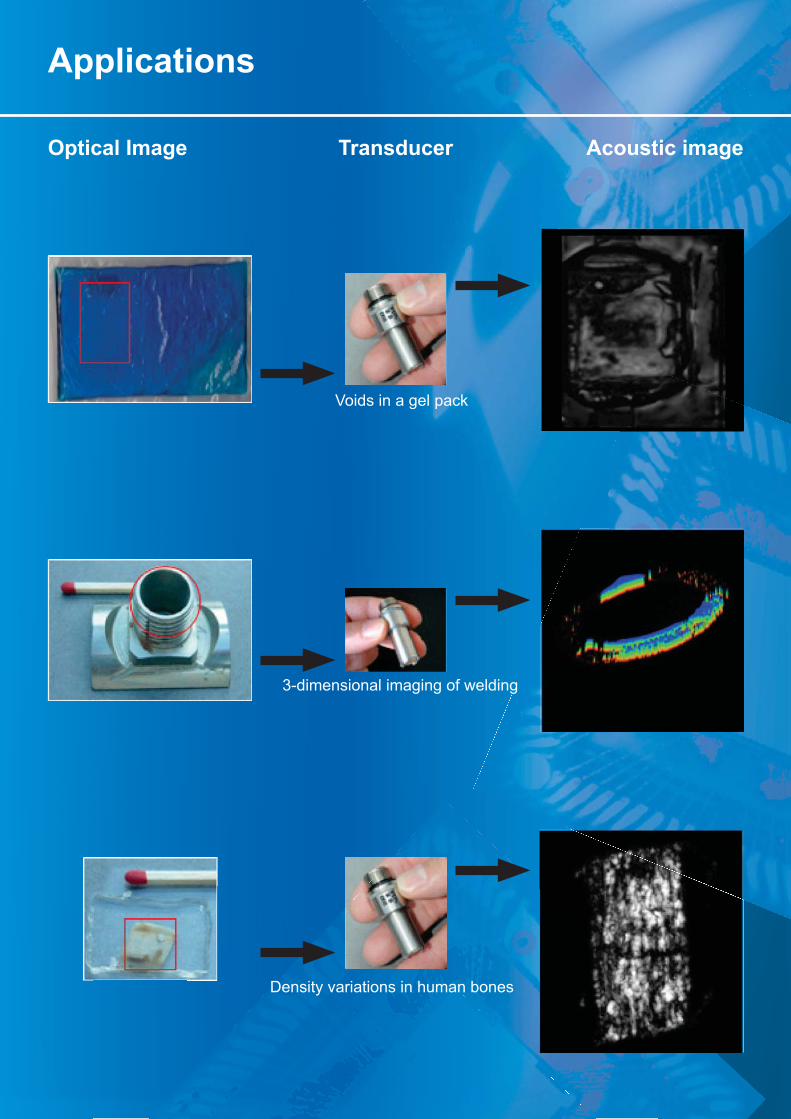
Optical Image Transducer Acoustic image
Voids in a gel pack
3-dimensional imaging of welding
Density variations in human bones

Applications
Optical Image Transducer Acoustic image
Package evaluations in JDEC-tray
Contacts in motherboards
Integrated circuit-packages
Semiconductor Component

Optical Image Transducer Acoustic image
Volume defects
Laquer above synthetic material
Material stress and crackpropagation (Vickers)
Applications

Optical Image Transducer Acoustic image
Interface evaluations of thin coatings
Voids in drive-shafts
#�����$��������������������
Applications

TransducerOptical Image Acoustic image
Applications
Soldering joint
Biolocal Structures of an urethra
Geological Structures
SAM
SEM
technical drawing of SMD

Notes
Your Notes:

Locations of KSI
KSI - Kraemer Sonic Industries GmbHAuf der Weih 11P.O. Box 1922D - 35745 HerbornGermany
Tel.: +49 (0) 2772 / 957 957Fax: +49 (0) 2772 / 957 958Email: [email protected]
Homepage: www.ksi-germany.de
Headquater in Germany R & D of KSI Production-Facility of KSI