Embed Size (px)
Citation preview
page 1
1)Bredenberg Teknik, www.bredenbergteknik.se
SCANDINAVIAN DRILLED MICRO PILE WALLS
Hakan Bredenberg, Dr Tech 1)
ABSTRACT
An excavation in an urban environment often requires vertical walls due to lack ofspace for slopes since there are streets, foundations, pipes and so on. Further, thesoil usually contains obstacles, like boulders and concrete debris, to mention a few.In Scandinavia, Micro Pile Walls have been developed for such conditions. Thedevelopment relies very much on improved drilling technology, but design methodshave also been refined. Tests have been made in order to utilize the full capacity ofdrilled, concrete filled, small diameter, thin walled steel tubes.
The use of drilled micro pile walls is not confined to city projects: This technique hasalso proven very useful for excavations in factories, where production must go onduring the piling stage, and the time schedule must be guaranteed. And even atlocations where there are no buildings or other objects nearby, drilled Micro PileWalls may be the only solution due to the presence of obstacles impossible topenetrate with conventional secant pile wall boring equipment, or other methods.
INTRODUCTIONA drilled pile wall is made up by a number of components, illustrated in Figure 1.
They main parts are
- drilled steel tubes, spaced at regular intervals- supporting members- infill members to cover the space between the tubes
The tubes are usually in the range 100 - 400 mm in diameter and the correspondingwall thickness is 5 -15 mm. The tubes can be filled with concrete and also supplied withreinforcement bars, or an H-beam, in order to increase bending capacity.
The horizontal support can be provided by soil or rock anchors, or any type of supportsuitable for the conditions. If the wall has limited height and the tub es are drilled intocompetent rock, the wall can function as a cantilever beam.
The cover between the drilled tubes can be covered by wood, steel plates or shotconcrete. The choice is determined by cost considerations and the durabilityrequirements.
page 2
1)Bredenberg Teknik, www.bredenbergteknik.se
Fig1. Drilled Micro Pile Wall components
APPLICATIONSAs mentioned above, the most common use of this technology is found in urbanexcavation sites where the ground contains obstacles difficult or impossible to penetratewith usual sheet piling equipment. Small tube diameter walls can also be required bythe working space available, as for example piling indoor in a basement. Further, noiseand other environmental related construction restrictions may call for small sizedequipment.
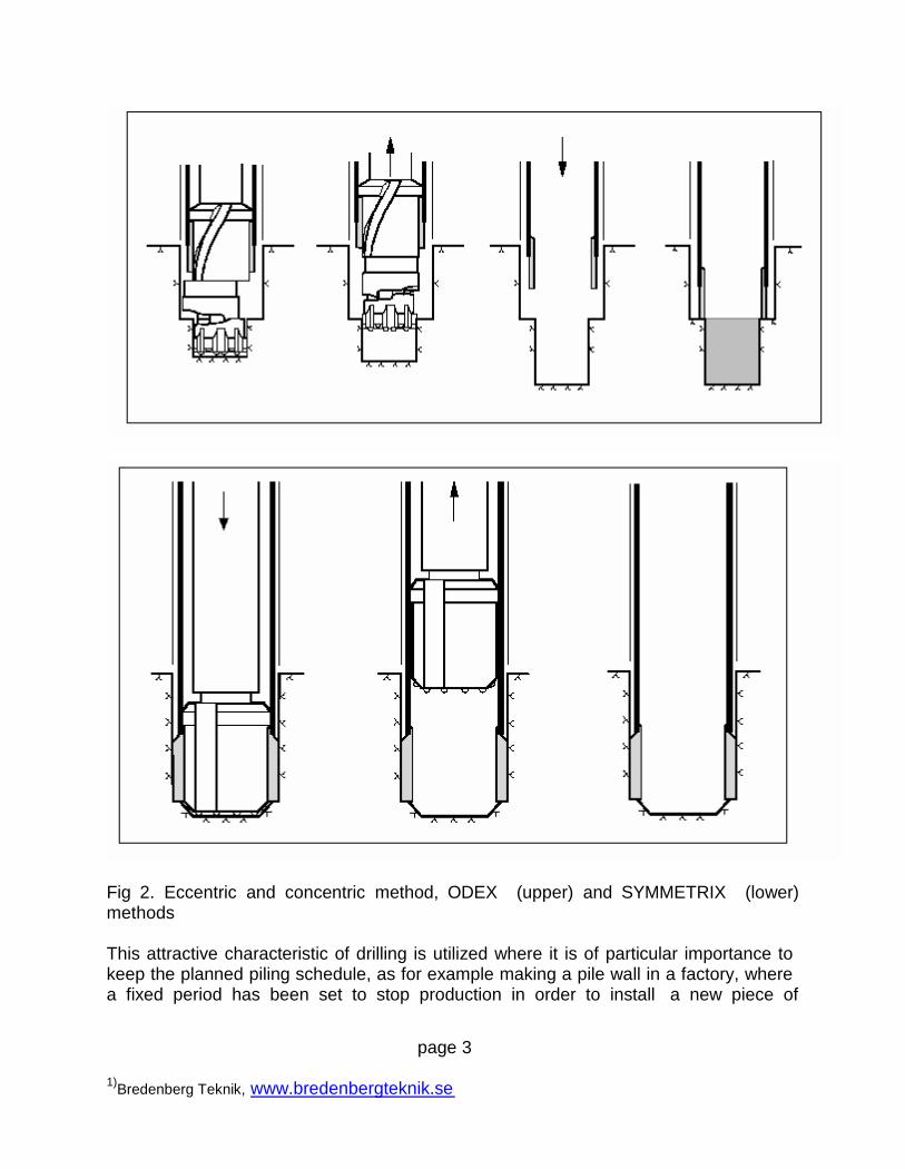
Experience shows that drilling is superior to many other pile installation methods as faras the ability to stay within construction time schedule is concerned. The kind of drillingassumed is drilling capable of penetrating hard bedrock and boulders, as for examplethe ODEX or the SYMMETRIX method. These two methods represent the t wo maindrilling techniques used, namely the eccentric and the concentric method, respectively,se figure 2.
page 3
1)Bredenberg Teknik, www.bredenbergteknik.se
Fig 2. Eccentric and concentric method, ODEX (upper) and SYMMETRIX (lower)methods
This attractive characteristic of drilling is utilized where it is of particular importance tokeep the planned piling schedule, as for example making a pile wall in a factory, wherea fixed period has been set to stop production in order to install a new piece of
page 4
1)Bredenberg Teknik, www.bredenbergteknik.se
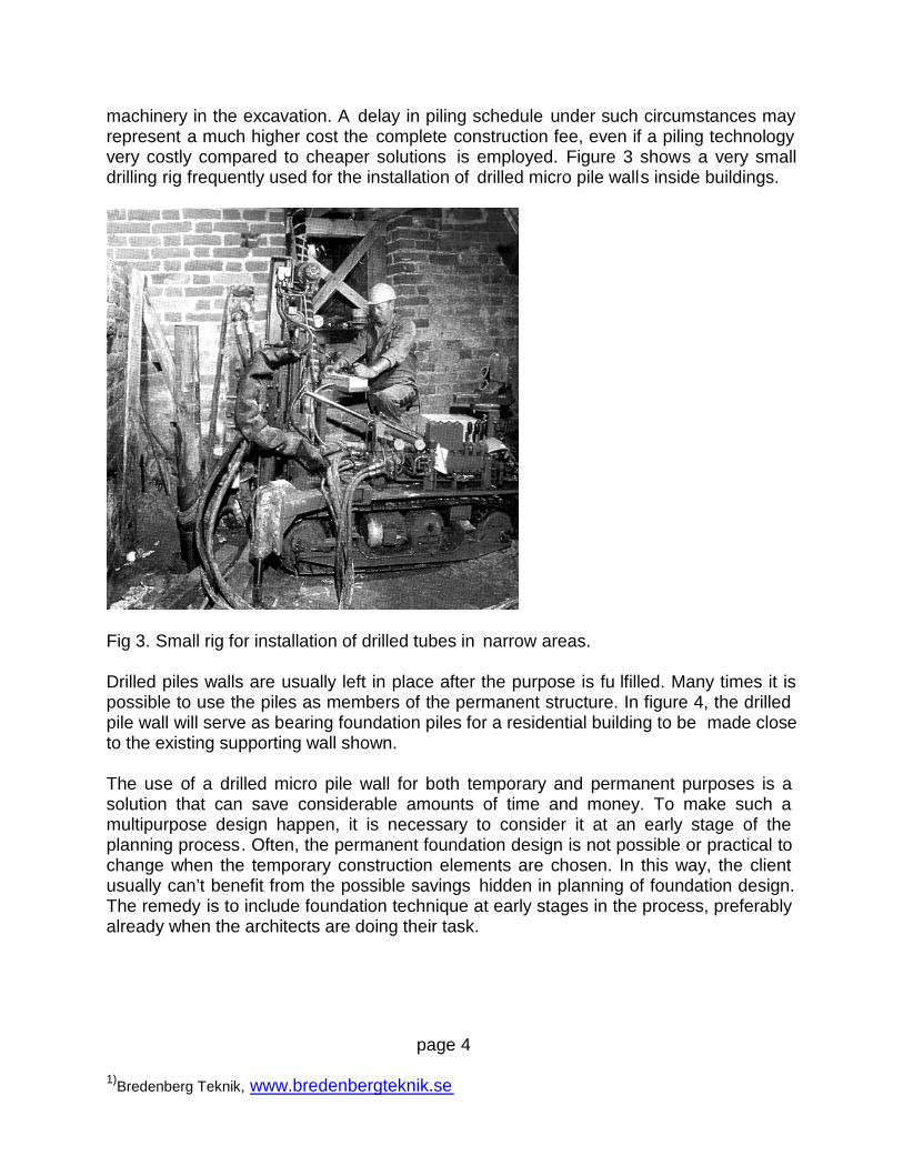
machinery in the excavation. A delay in piling schedule under such circumstances mayrepresent a much higher cost the complete construction fee, even if a piling technologyvery costly compared to cheaper solutions is employed. Figure 3 shows a very smalldrilling rig frequently used for the installation of drilled micro pile walls inside buildings.
Fig 3. Small rig for installation of drilled tubes in narrow areas.
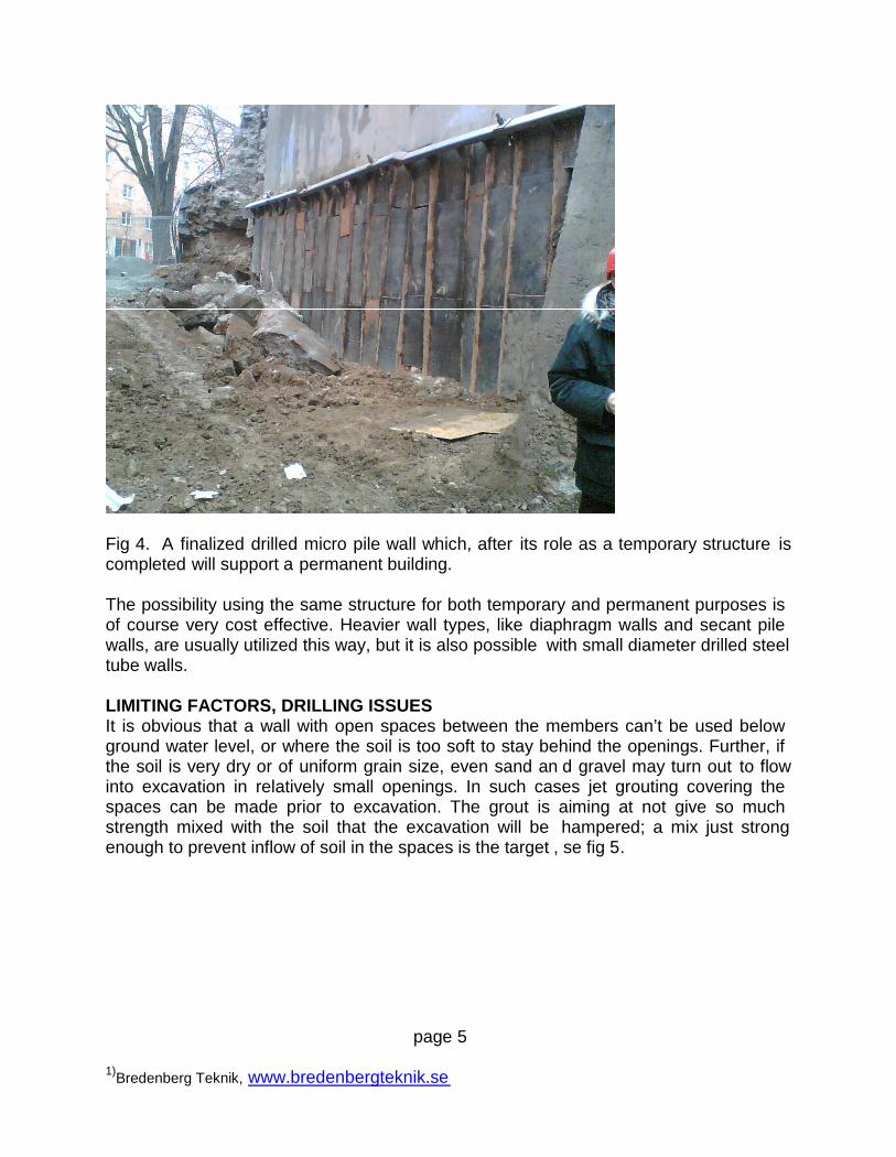
Drilled piles walls are usually left in place after the purpose is fu lfilled. Many times it ispossible to use the piles as members of the permanent structure. In figure 4, the drilledpile wall will serve as bearing foundation piles for a residential building to be made closeto the existing supporting wall shown.
The use of a drilled micro pile wall for both temporary and permanent purposes is asolution that can save considerable amounts of time and money. To make such amultipurpose design happen, it is necessary to consider it at an early stage of theplanning process. Often, the permanent foundation design is not possible or practical tochange when the temporary construction elements are chosen. In this way, the clientusually can’t benefit from the possible savings hidden in planning of foundation design.The remedy is to include foundation technique at early stages in the process, preferablyalready when the architects are doing their task.
page 5
1)Bredenberg Teknik, www.bredenbergteknik.se
Fig 4. A finalized drilled micro pile wall which, after its role as a temporary structure iscompleted will support a permanent building.
The possibility using the same structure for both temporary and permanent purposes isof course very cost effective. Heavier wall types, like diaphragm walls and secant pilewalls, are usually utilized this way, but it is also possible with small diameter drilled steeltube walls.
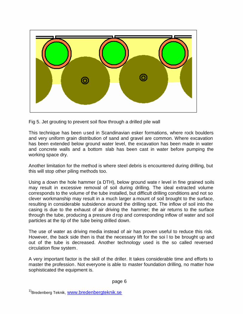
LIMITING FACTORS, DRILLING ISSUESIt is obvious that a wall with open spaces between the members can’t be used belowground water level, or where the soil is too soft to stay behind the openings. Further, ifthe soil is very dry or of uniform grain size, even sand an d gravel may turn out to flowinto excavation in relatively small openings. In such cases jet grouting covering thespaces can be made prior to excavation. The grout is aiming at not give so muchstrength mixed with the soil that the excavation will be hampered; a mix just strongenough to prevent inflow of soil in the spaces is the target , se fig 5.
page 6
1)Bredenberg Teknik, www.bredenbergteknik.se
Fig 5. Jet grouting to prevent soil flow through a drilled pile wall
This technique has been used in Scandinavian esker formations, where rock bouldersand very uniform grain distribution of sand and gravel are common. Where excavationhas been extended below ground water level, the excavation has been made in waterand concrete walls and a bottom slab has been cast in water before pumping theworking space dry.
Another limitation for the method is where steel debris is encountered during drilling, butthis will stop other piling methods too.
Using a down the hole hammer (a DTH), below ground wate r level in fine grained soilsmay result in excessive removal of soil during drilling. The ideal extracted volumecorresponds to the volume of the tube installed, but difficult drilling conditions and not soclever workmanship may result in a much larger a mount of soil brought to the surface,resulting in considerable subsidence around the drilling spot. The inflow of soil into thecasing is due to the exhaust of air driving the hammer; the air returns to the surfacethrough the tube, producing a pressure d rop and corresponding inflow of water and soilparticles at the tip of the tube being drilled down.
The use of water as driving media instead of air has proven useful to reduce this risk.However, the back side then is that the necessary lift for the soi l to be brought up andout of the tube is decreased. Another technology used is the so called reversedcirculation flow system.
A very important factor is the skill of the driller. It takes considerable time and efforts tomaster the profession. Not everyone is able to master foundation drilling, no matter howsophisticated the equipment is.
page 7
1)Bredenberg Teknik, www.bredenbergteknik.se
It should be mentioned also that drilling involves many relatively dangerous moments,as dealing with heavy, powerful rotation components, lifting of heavy parts (dril lingpipes, for example), and so on. Add a noisy, dusty, muddy work site environment, oftenin very confined spaces together with other moving construction machines. Thus, notsurprisingly, the accident rate is very high here.
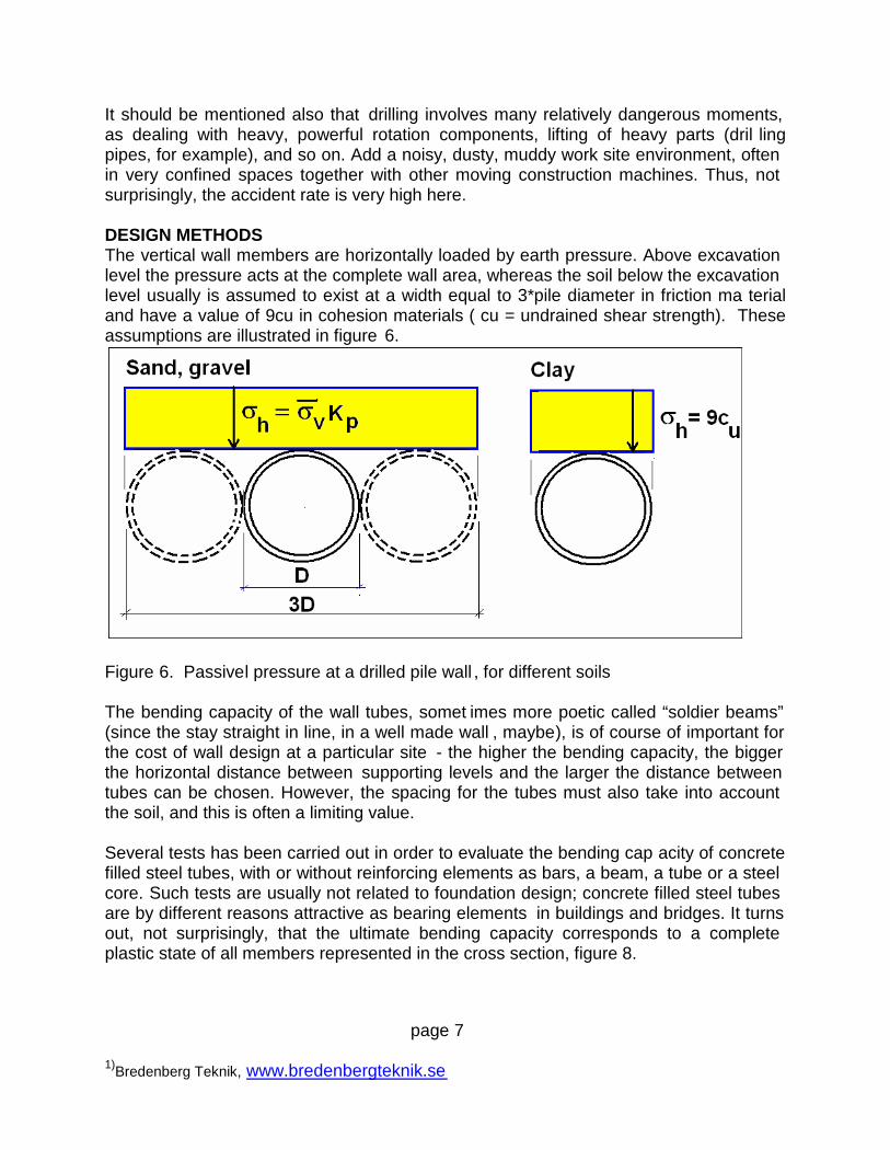
DESIGN METHODSThe vertical wall members are horizontally loaded by earth pressure. Above excavationlevel the pressure acts at the complete wall area, whereas the soil below the excavationlevel usually is assumed to exist at a width equal to 3*pile diameter in friction ma terialand have a value of 9cu in cohesion materials ( cu = undrained shear strength). Theseassumptions are illustrated in figure 6.
Figure 6. Passivel pressure at a drilled pile wall , for different soils
The bending capacity of the wall tubes, somet imes more poetic called “soldier beams”(since the stay straight in line, in a well made wall , maybe), is of course of important forthe cost of wall design at a particular site - the higher the bending capacity, the biggerthe horizontal distance between supporting levels and the larger the distance betweentubes can be chosen. However, the spacing for the tubes must also take into accountthe soil, and this is often a limiting value.
Several tests has been carried out in order to evaluate the bending cap acity of concretefilled steel tubes, with or without reinforcing elements as bars, a beam, a tube or a steelcore. Such tests are usually not related to foundation design; concrete filled steel tubesare by different reasons attractive as bearing elements in buildings and bridges. It turnsout, not surprisingly, that the ultimate bending capacity corresponds to a completeplastic state of all members represented in the cross section, figure 8.
page 8
1)Bredenberg Teknik, www.bredenbergteknik.se
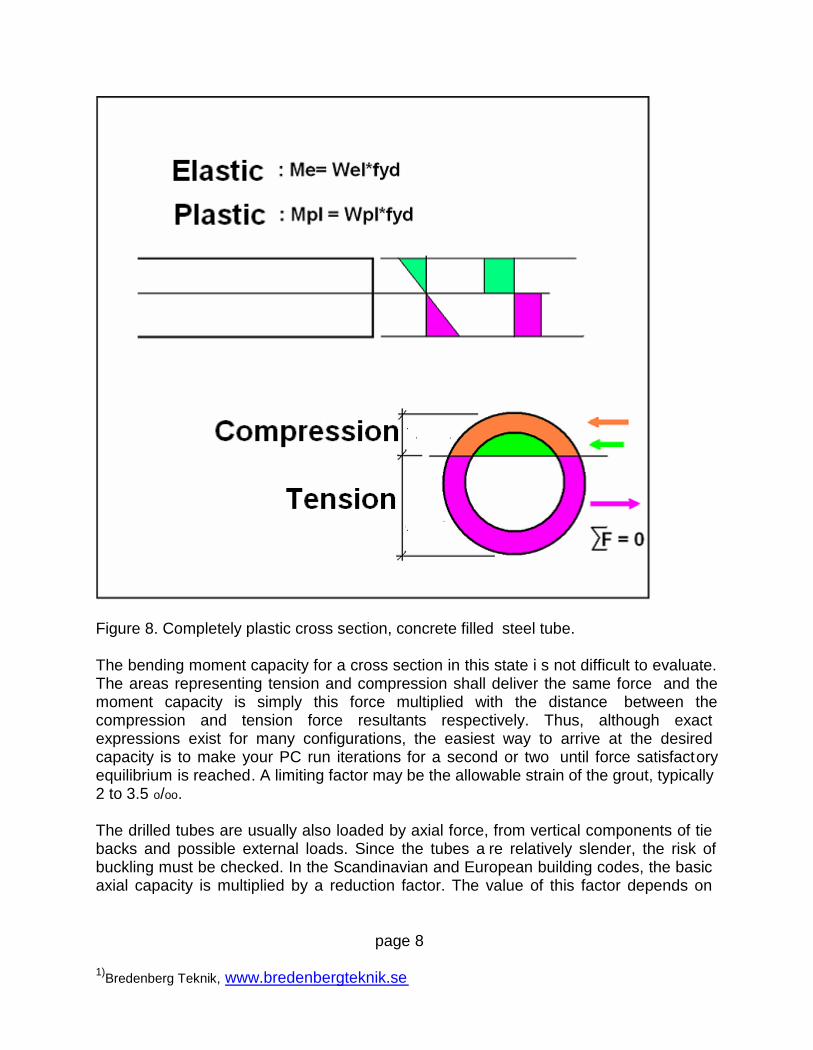
Figure 8. Completely plastic cross section, concrete filled steel tube.
The bending moment capacity for a cross section in this state i s not difficult to evaluate.The areas representing tension and compression shall deliver the same force and themoment capacity is simply this force multiplied with the distance between thecompression and tension force resultants respectively. Thus, although exactexpressions exist for many configurations, the easiest way to arrive at the desiredcapacity is to make your PC run iterations for a second or two until force satisfactoryequilibrium is reached. A limiting factor may be the allowable strain of the grout, typically2 to 3.5 o/oo.
The drilled tubes are usually also loaded by axial force, from vertical components of tiebacks and possible external loads. Since the tubes a re relatively slender, the risk ofbuckling must be checked. In the Scandinavian and European building codes, the basicaxial capacity is multiplied by a reduction factor. The value of this factor depends on
page 9
1)Bredenberg Teknik, www.bredenbergteknik.se
slenderness ratio, initial deflection assumed, a nd cross section geometry, built instresses and so on.
The combined effect of acting bending moment (Ms) and axial load (Ns) is analyzed byan interaction formula, as for example
Ns/Nd + Ms/Md < 1 … (1)
where Nd and Md is the axial and bending moment capacity respectively.
Also the risk of local buckling of thin walled tubes, as for example the tube at the end ofits life time, after design value of corrosion wall thickness reduction, should be checkedin this respect. Concrete, or mortar, filling is an effective way of increase the localbuckling capacity and the filling also eliminates inside corrosion.
QUALITY CONTROLA drilled micro pile wall can be checked against given tolerance s and quality demandsmuch better than many other types of wall structures installed in the ground. Forexample, the integrity and the spatial location of every inst alled tube can be checkedbefore excavation starts.
Drilling also means that the tubes can be more accurately positioned than driven orvibrated elements. This is particularly true for concentric drilling methods. When pilewall elements must be installed close to existing structures buried in the ground andnear bearing piles its of course imp ortant to be able to follow the path of the tubebrought down.
FUTURE DEVELOPMENTAlthough development of technical improvements in foundation technology is known tobe notoriously slow, as in building industry all together, technology is improved as theyears goes by. What can we expect as far as drilled micro pile walls are considered?
- drilling technology will continue to improve productivity and adaptation to demandsrelated to environmental requirements. Today the normal upper limit of steel tubediameter for tubes of drilled walls is around 300 mm, but the tendency is that this figureis increasing all the time.
- the use of high strength concrete for filling the tubes may result in largely increaseaxial and bending capacities. However, several e fforts to bring these compounds to useat sites must be made. Its one thing to make a solution work in the laboratory but it’s adifferent cup of tea to make it function in production. Not to mention the acceptancefrom the authorities issuing codes.
page 10
1)Bredenberg Teknik, www.bredenbergteknik.se
- splicing techniques can be very much improved - today welding is the most usedtechnique for splicing tubes, but the control prescribed and the difficulty to meet thecode requirements in production, makes alternatives urgently needed.
- general solutions for typical situations - today every drilled micro pile project must behandled as if done never before - a number of general accepted designs could simplifythe use (maybe consultants disagree …)
- making it possible to withdraw and retrieve the tubes an d other wall elements for futureuse. Today they are usually left in place, which is contradictory to the policy of r euse ofmaterial and components, sometimes even regardless of the price tag connected …
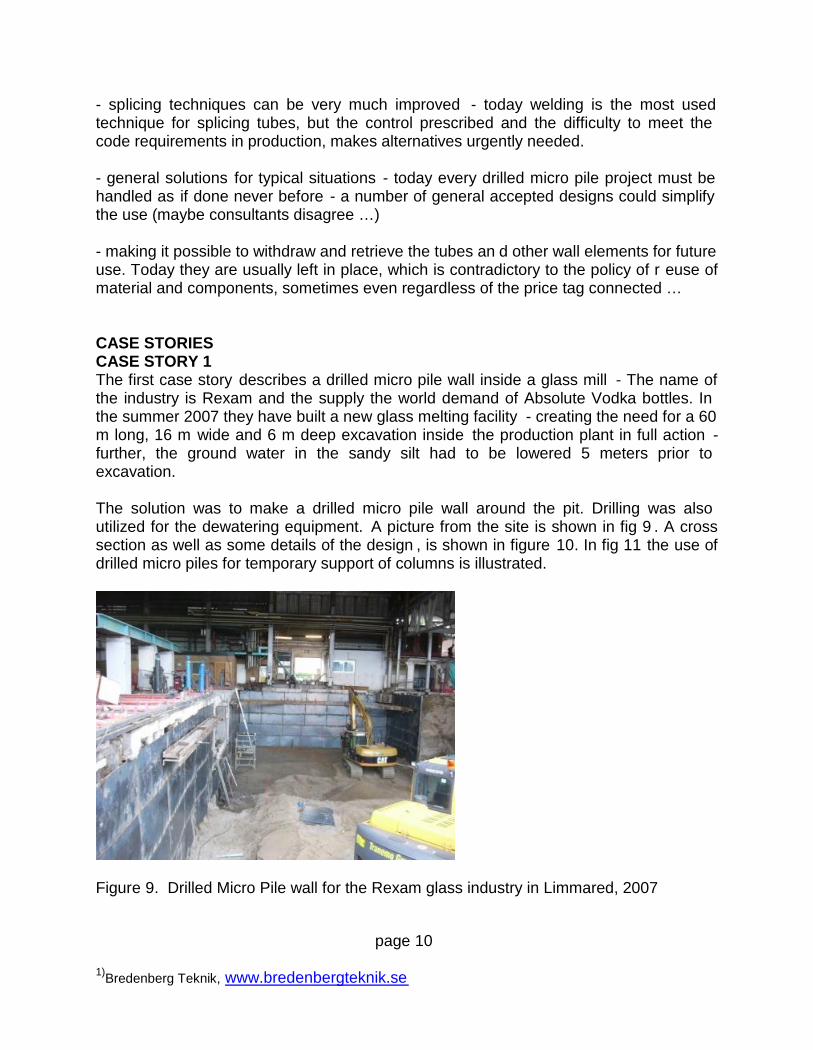
CASE STORIESCASE STORY 1The first case story describes a drilled micro pile wall inside a glass mill - The name ofthe industry is Rexam and the supply the world demand of Absolute Vodka bottles. Inthe summer 2007 they have built a new glass melting facility - creating the need for a 60m long, 16 m wide and 6 m deep excavation inside the production plant in full action -further, the ground water in the sandy silt had to be lowered 5 meters prior toexcavation.
The solution was to make a drilled micro pile wall around the pit. Drilling was alsoutilized for the dewatering equipment. A picture from the site is shown in fig 9 . A crosssection as well as some details of the design , is shown in figure 10. In fig 11 the use ofdrilled micro piles for temporary support of columns is illustrated.
Figure 9. Drilled Micro Pile wall for the Rexam glass industry in Limmared, 2007
page 11
1)Bredenberg Teknik, www.bredenbergteknik.se
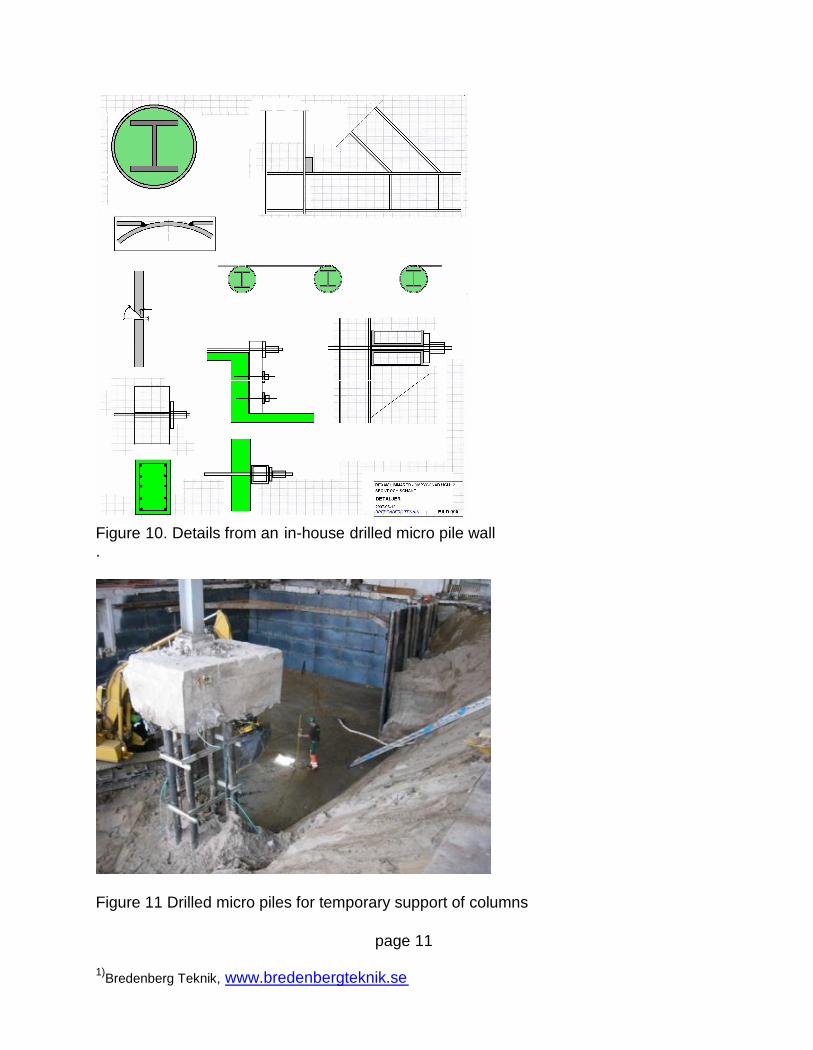
Figure 10. Details from an in-house drilled micro pile wall.
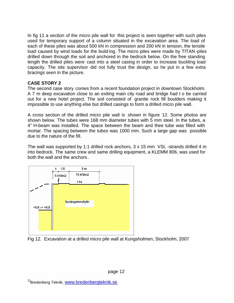
Figure 11 Drilled micro piles for temporary support of columns
page 12
1)Bredenberg Teknik, www.bredenbergteknik.se
In fig 11 a section of the micro pile wall for this project is seen together with such pilesused for temporary support of a column situated in the excavation area. The load ofeach of these piles was about 500 kN in compression and 200 kN in tension, the tensileload caused by wind loads for the build ing. The micro piles were made by TITAN -pilesdrilled down through the soil and anchored in the bedrock below. On the free standinglength the drilled piles were cast into a steel casing in order to increase buckling loadcapacity. The site supervisor did not fully trust the design, so he put in a few extrabracings seen in the picture.
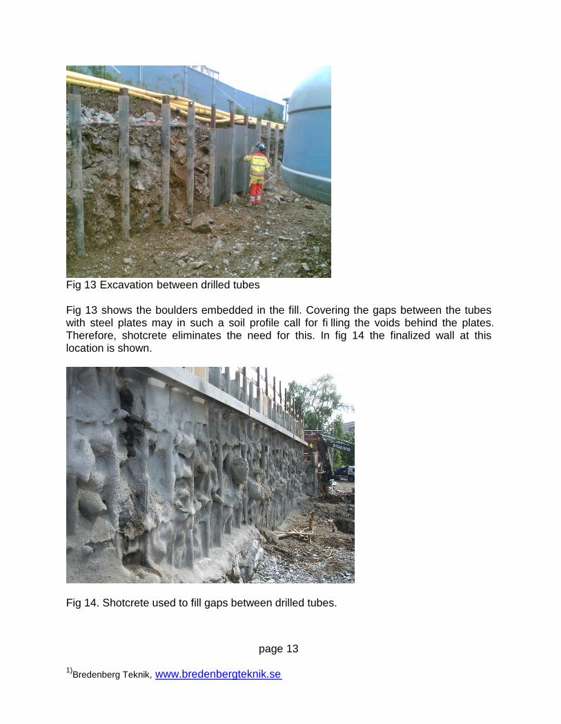
CASE STORY 2The second case story comes from a recent foundation project in downtown Stockholm.A 7 m deep excavation close to an exiting main city road and bridge had t o be carriedout for a new hotel project. The soil consisted of granite rock fill boulders making itimpossible to use anything else but drilled casings to form a drilled micro pile wall.
A cross section of the drilled micro pile wall is shown in figure 12. Some photos areshown below. The tubes were 168 mm diameter tubes with 5 mm steel. In the tubes, a4” H-beam was installed. The space between the beam and thee tube was filled withmortar. The spacing between the tubes was 1000 mm. Such a large gap was possibledue to the nature of the fill.
The wall was supported by 1:1 drilled rock anchors, 3 x 15 mm VSL -strands drilled 4 minto bedrock. The same crew and same drilling equipment, a KLEMM 806, was used forboth the wall and the anchors .
Fig 12. Excavation at a drilled micro pile wall at Kungsholmen, Stockholm, 2007
page 13
1)Bredenberg Teknik, www.bredenbergteknik.se
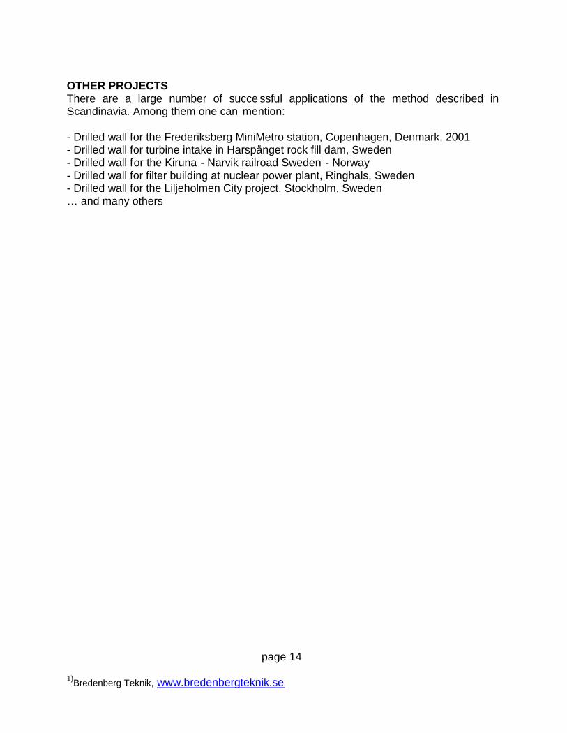
Fig 13 Excavation between drilled tubes
Fig 13 shows the boulders embedded in the fill. Covering the gaps between the tubeswith steel plates may in such a soil profile call for fi lling the voids behind the plates.Therefore, shotcrete eliminates the need for this. In fig 14 the finalized wall at thislocation is shown.
Fig 14. Shotcrete used to fill gaps between drilled tubes.
page 14
1)Bredenberg Teknik, www.bredenbergteknik.se
OTHER PROJECTSThere are a large number of succe ssful applications of the method described inScandinavia. Among them one can mention:
- Drilled wall for the Frederiksberg MiniMetro station, Copenhagen, Denmark, 2001- Drilled wall for turbine intake in Harspånget rock fill dam, Sweden- Drilled wall for the Kiruna - Narvik railroad Sweden - Norway- Drilled wall for filter building at nuclear power plant, Ringhals, Sweden- Drilled wall for the Liljeholmen City project, Stockholm, Sweden… and many others