Embed Size (px)
Citation preview

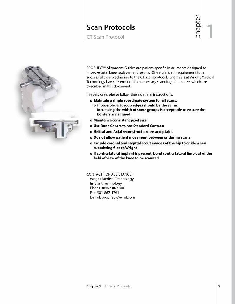
Scan Protocols
CT Scan Protocols
MRI Scan Protocols
Submitting Scans
Function of PROPHECY® Guides
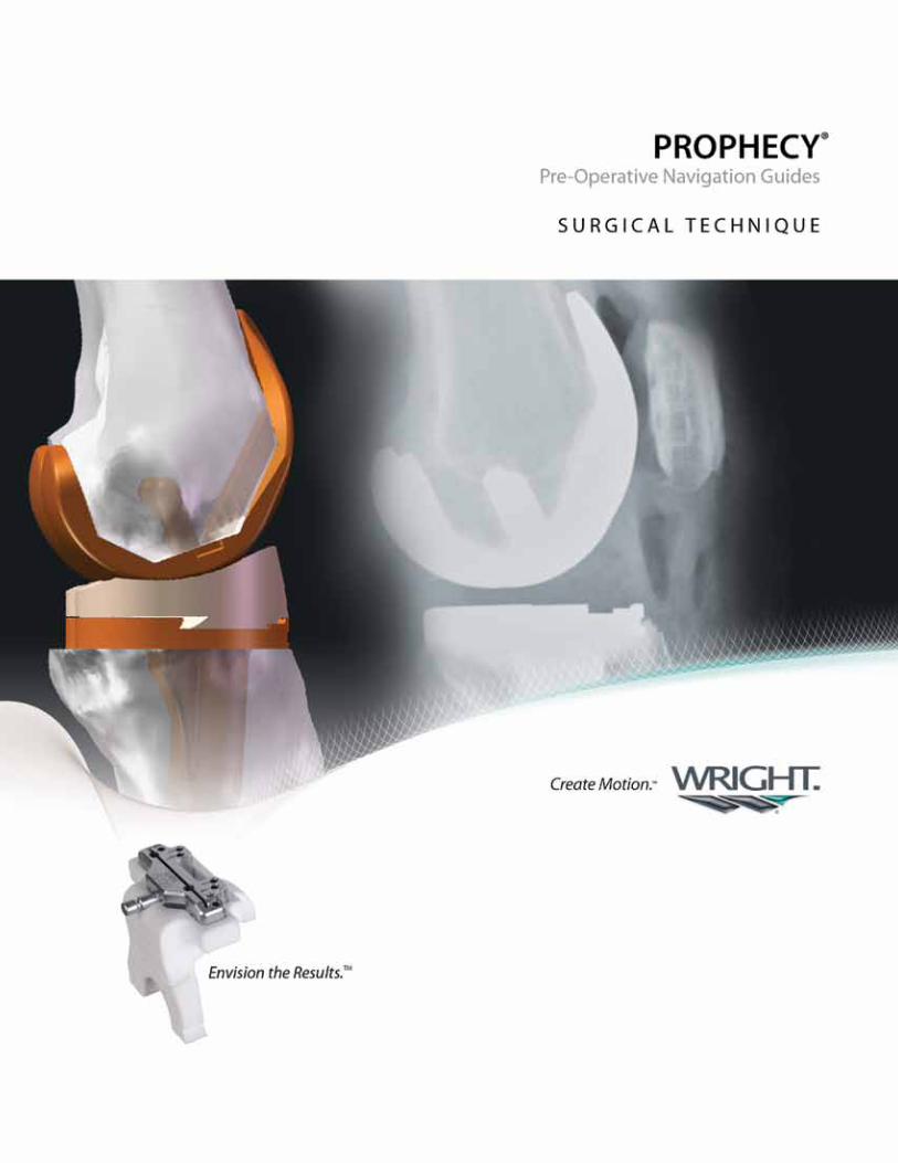
Surgical Technique
Femoral Preparation
Proximal Tibial Resection
Tibial Preparation
Patellar Preparation and Removal of Posterior Femoral Osteophytes
Trial Reduction and Implant Insertion
Femoral Trialing and Implantion
Cemented Tibial Base Implantation
Patellar Implantation
Tibial Insert Seating
Additional Information
BIOFOAM® Tibial Base Preparation
Recessed Patella Instrumentation
Flexion/Extension Gap Measurement
2mm Resection Guide
Re-Cutting the Distal Femur
Efficient Use of Fixation Pins
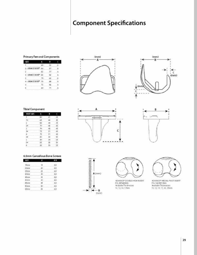
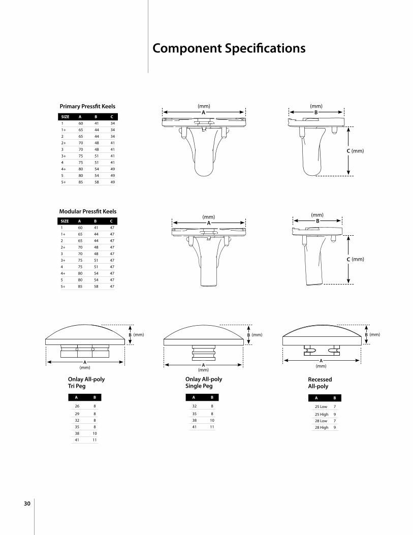
Component Specifications
Chapter 1
3
6
Chapter 2 6
Chapter 3 10
Chapter 4 11
12-14
15-17
18-21
22
Chapter 5
23
24
24
24-25
Chapter 6
26
27
27
28
28
28
29-30
Proper surgical procedures and techniques are the responsibility of the medical professional. The following guidelines are furnished for information purposes only. Each surgeon must evaluate the appropriateness of the procedures based on his or her personal medical training and experience. Prior to use of the system, the surgeon should refer to the product package insert for complete warnings, precautions, indications, contraindications and adverse effects. Package inserts are also available by contacting Wright Medical Technology, Inc.
Contents
3
chap
ter
1Scan ProtocolsCT Scan Protocol
Chapter 1 CT Scan Protocols
PROPHECY® Alignment Guides are patient specific instruments designed to improve total knee replacement results. One significant requirement for a successful case is adhering to the CT scan protocol. Engineers at Wright Medical Technology have determined the necessary scanning parameters which are described in this document.
In every case, please follow these general instructions:
oMaintainasinglecoordinatesystemforallscans. oIfpossible,allgroupedgesshouldbethesame. Increasingthewidthofsomegroupsisacceptabletoensurethe bordersarealigned.
o Maintainaconsistentpixelsize
o UseBoneContrast,notStandardContrast
o HelicalandAxialreconstructionareacceptable
o Donotallowpatientmovementbetweenorduringscans
o Includecoronalandsagittalscoutimagesofthehiptoanklewhen submittingfilestoWright
o Ifcontra-lateralimplantispresent,bendcontra-laterallimboutofthe fieldofviewofthekneetobescanned
COnTACT FOR ASSISTAnCE: Wright Medical Technology Implant Technology Phone: 800-238-7188 Fax: 901-867-4791 E-mail: [email protected]
4 Chapter 1 CT Scan Protocols
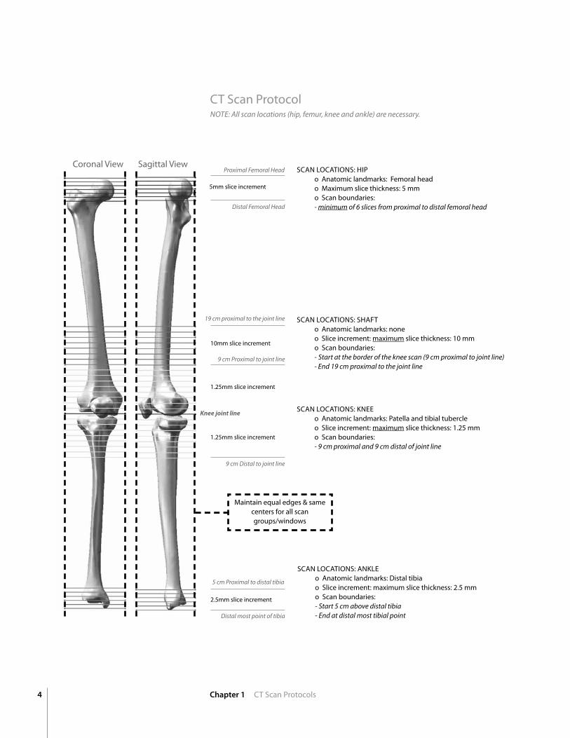
Note: All scan locations (hip, femur, knee and ankle) are necessary.
SCAn LOCATIOnS: HIP o Anatomic landmarks: Femoral head o Maximum slice thickness: 5 mm o Scan boundaries: - minimum of 6 slices from proximal to distal femoral head
Proximal Femoral Head
Distal Femoral Head
19 cm proximal to the joint line
9 cm Distal to joint line
9 cm Proximal to joint line
Knee joint line
5 cm Proximal to distal tibia
Distal most point of tibia
5mm slice increment
10mm slice increment
1.25mm slice increment
1.25mm slice increment
2.5mm slice increment
SCAn LOCATIOnS: SHAFT o Anatomic landmarks: none o Slice increment: maximum slice thickness: 10 mm o Scan boundaries: - Start at the border of the knee scan (9 cm proximal to joint line) - end 19 cm proximal to the joint line
SCAn LOCATIOnS: KnEE o Anatomic landmarks: Patella and tibial tubercle o Slice increment: maximum slice thickness: 1.25 mm o Scan boundaries: - 9 cm proximal and 9 cm distal of joint line
SCAn LOCATIOnS: AnKLE o Anatomic landmarks: Distal tibia o Slice increment: maximum slice thickness: 2.5 mm o Scan boundaries: - Start 5 cm above distal tibia - end at distal most tibial point
CT Scan Protocol
Maintain equal edges & same centers for all scan groups/windows
Coronal View Sagittal View
5Chapter 1 CT Scan Protocols
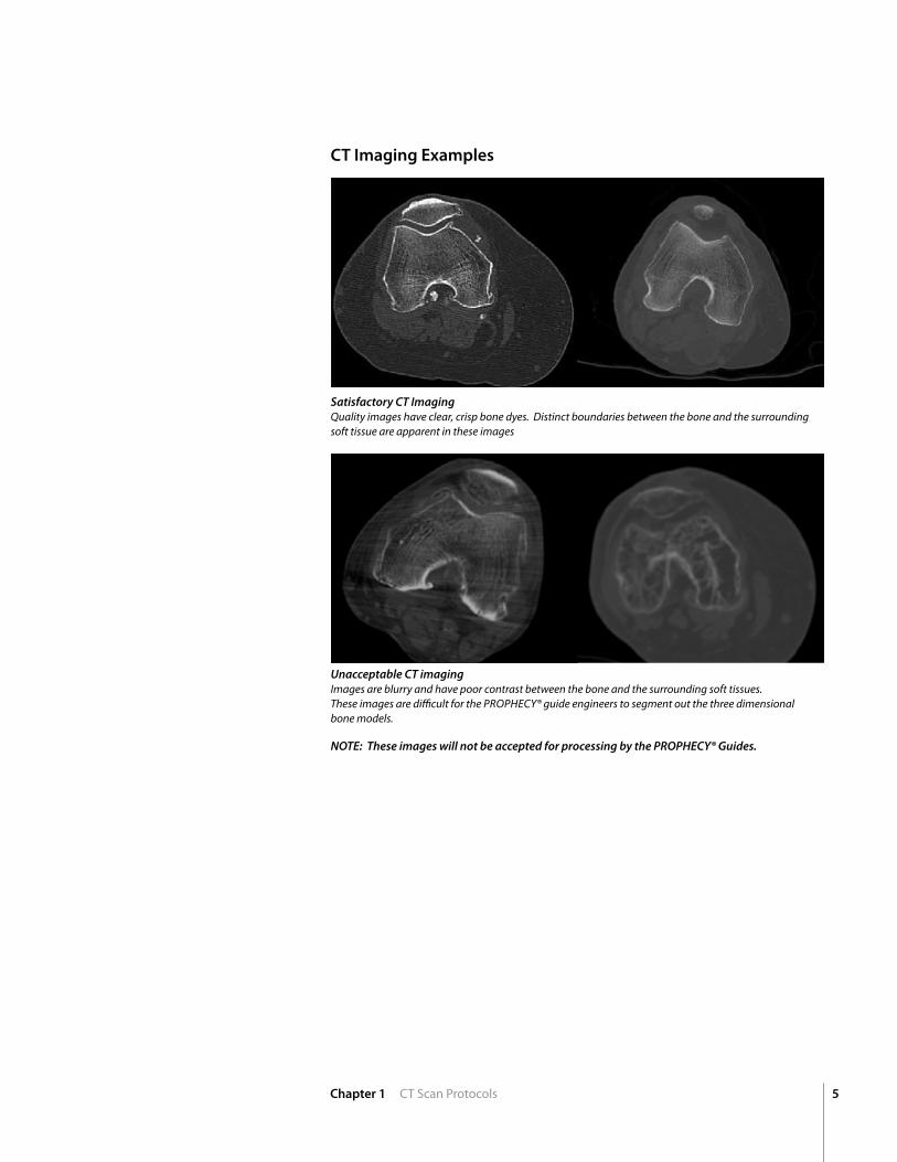
Satisfactory CT Imaging Quality images have clear, crisp bone dyes. Distinct boundaries between the bone and the surrounding soft tissue are apparent in these images
Unacceptable CT imaging Images are blurry and have poor contrast between the bone and the surrounding soft tissues. these images are difficult for the ProPHecy® guide engineers to segment out the three dimensionalbone models.
NOTE: These images will not be accepted for processing by the PROPHECY® Guides.
CT Imaging Examples
chap
ter
6 Chapter 2 MRI Scan Protocols
MRI Scan Protocol2
PROPHECY® Alignment Guides are patient specific instruments designed to decrease time in the operating room and to improve total knee replacement results. One significant requirement for a successful case is adhering to the MRI scan protocol. Engineers at Wright Medical Technology have determined the necessary scanning parameters which are described in this document.
In every case, please follow these general instructions: o Donotallowpatientmovementduringscans.
o Alignthepatientsuchthatscansofthefemurandtibia,usingthebody
coils,encompasstheentirefemurandtibia,respectively.
o Ifpatientheightpreventsentirebonefromfittinginthefieldof
view,thehipandanklearelesscriticalthanthedistalfemurand
proximaltibia.
o Allthreescanlocationsmustbeacquired(Femur,Knee,andTibia).
o Performthetwobodycoilscanssuccessivelypriortoswitching
tothekneecoil
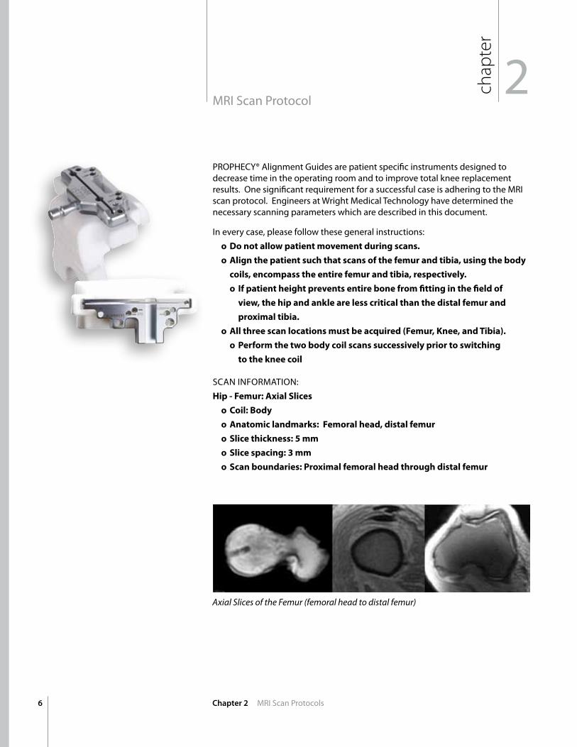
SCAn InFORMATIOn:Hip-Femur:AxialSlices
o Coil:Body
o Anatomiclandmarks:Femoralhead,distalfemur
o Slicethickness:5mm
o Slicespacing:3mm
o Scanboundaries:Proximalfemoralheadthroughdistalfemur
Axial Slices of the Femur (femoral head to distal femur)
7Chapter 2 MRI Scan Protocols
Axial Slices of the tibia (proximal tibia to distal tibia)
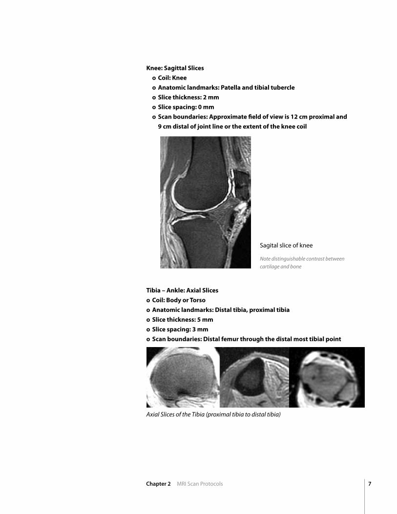
Knee:SagittalSlices
o Coil:Knee
o Anatomiclandmarks:Patellaandtibialtubercle
o Slicethickness:2mm
o Slicespacing:0mm
o Scanboundaries:Approximatefieldofviewis12cmproximaland
9cmdistalofjointlineortheextentofthekneecoil
Note distinguishable contrast between cartilage and bone
Tibia–Ankle:AxialSlices
o Coil:BodyorTorso
o Anatomiclandmarks:Distaltibia,proximaltibia
o Slicethickness:5mm
o Slicespacing:3mm
o Scanboundaries:Distalfemurthroughthedistalmosttibialpoint
Sagital slice of knee
8
NOTE: All scan locations (femur, tibia and knee) are necessary.
Chapter 2 MRI Scan Protocol
Knee joint line
SCAn LOCATIOn: FEMUR: (AxIAL SLICES) o Femur (Hip to Knee): Axial Slices o Coil: Body or Torso o Anatomic landmarks: Femoral head, distal femur o Slice thickness: 5 mm o Slice spacing: 3 mm o Scan boundaries: Proximal femoral head through distal femur
Proximal femoral head
Distal most point of tibia
Slice thickness: 5mm
Slice spacing: 3mm
SCAn LOCATIOn: TIBIA: AxIAL SLICES o Tibia (Knee to Ankle): Axial Slices o Coil: Body or Torso o Anatomic landmarks: Distal tibia, proximal tibia o Slice thickness: 5 mm o Slice spacing: 3 mm o Scan boundaries: Distal femur through the distal most tibial point
Coronal View Sagittal View
Axial Slices Body Coil
Slice thickness: 5mm
Slice spacing: 3mm
Axial Slices Body Coil
2MRI Scan Protocol ch
apter
Slice thickness: 2mm Slice spacing: 0mm
12cm Proximal to joint line
Sagital Slices Knee Coil
9cm Distal to joint line
SCAn LOCATIOn: KnEE: (SAGITTAL SLICES) o Coil: Knee o Anatomic landmarks: Patella and tibial tubercle o Slice thickness: 2 mm o Slice spacing: 0 mm o Scan boundaries: Approximate field of view is 12 cm proximal and 9 cm distal of joint line
Coronal View Sagittal View
Note: If patient height prevents the entire bone from fitting in the field of view, the hip and ankle are less critical than the distal femur and proximal tibia.
9
chap
ter
2MRI Scan Protocol
Chapter 2 MRI Scan Protocols
chap
ter
Note: Parameters listed in table 1 & 2 are recommended for a 1.5 tesla Magnet. Different Magnetic Field Strengths or Scanner Settings may require variation of parameters to achieve quality images shown in Figures 1, 2, and 3
Table 1 | MRI Scanner Settings
Scan ID HIP-FEMUR KnEE TIBIA-AnKLE
Coil Body (8CH) HD TR Knee Body (8CH)
Pulse Sequence See table 2 Below See table 2 Below See table 2 Below
TR 2700 (2 Acq) 20-500 ms 2700 (2 Acq)
TE min full 2-50 ms min full
Plane Axial Sagittal Axial
Slice Thickness (mm) 5 2 5
Slice Spacing 3 0 3
Matrix 256x256 512x256 256x256
Voxel/Pixel Size .27mm .27mm .27mm
Acquisition Time (min) ~ 6:00 ~ 9:00 ~ 6:00
Phase Encoding RL AP RL
Table 2 | Pulse Sequence
Manufacturer HIP-FEMUR KnEE TIBIA-AnKLE
GE 2D FSE-xL (PD) 3D SPGR FATSAT 2D FSE-xL (PD)
Siemens TSE (PD) 3D FATSAT FLASH TSE (PD)
Philips TSE (PD) 3D-SPIR-FFE TSE (PD)
Toshiba FSE (PD) RF Spoiled FE FSE (PD)
Hitachi FSE (PD) GE/GFE FSE (PD)
chap
ter
10
3Submitting the Scan
Chapter 3 Submitting the Scan
Rapid Electronic Scan TransferPre-Operative CT and MRI scans may be sent to the PROPHECY® guides engineering team through our rapid electronic transfer system. https://prophecyscans.wmt.com
Please follow these steps to request an account and transfer scans:
1. E-mail [email protected] with the e-mail address of the person who needs access to the system (no other information is needed)
2. Within a few hours, an invitation message will be sent to that address with instructions to complete registration on the scan transfer site.
** upload times may vary based on connection speed.
Mail CD • Ensure the dicom files are located on the CT Scan CD
• Mail the CD to: Wright Medical Technology: 5677 Airline Rd., Arlington, Tn 38002 Attention: Prophecy Lab
Satisfactory MRI Imaging Quality images have bright cartilage and dark bone. there are clear, distinct boundaries between the bone, cartilage and the and the surrounding tissue.
Unacceptable MRI Imaging there are numerous examples of bad MrI images. these can include using an incorrect sequence, blurry boundaries or unclear cartilage.
chap
ter
MRI Imaging Example
Note: there are two options to choose from when submitting pre-operative scans to Wright; either electronic transfer or standard mail. either is acceptable.
11Chapter 3 Function of the PROPHECY® Guides
3Function of the PROPHECY® Guides ch
apter
PROPHECY® Guides are available in two versions: “Pin Alignment” or “Alignment and Resection.” The pin alignment guides are designed for use in minimally-invasive exposures. The alignment and resection guides are designed to further reduce the steps of the surgical procedure.
Anterior holes align pins of 9mm oDYSSeY® Distal Resection Guide to set depth and valgus angle of distal resection
FemoralPinAlignmentGuide FemoralAlignment&ResectionGuide
TibialPinAlignmentGuide TibialAlignment&ResectionGuide
Distal holes set femoral rotation of 4-in-1 resection guides
Accepts 9 mm oDYSSeY® Distal Femoral Resection Guide
Anterior holes align pins of oDYSSeY® tibial Resection Guide to control resection depth, posterior and M/L slope
Accepts oDYSSeY® tibial Resection Guide
All PROPHECY® Femoral Guides are only compatible with ODYSSEY® Femoral Resection Guides (K001-2659). All PROPHECY® Tibial Guides are only compatible with ODYSSEY® tibial resection guides (K004-007L for left; K004-007R for right).
12
chap
ter
FEMORAL PREPARATIOnNOTE: Femoral resections should be made before tibial resections to ensure adequate joint space for the tibial alignment drill guides.
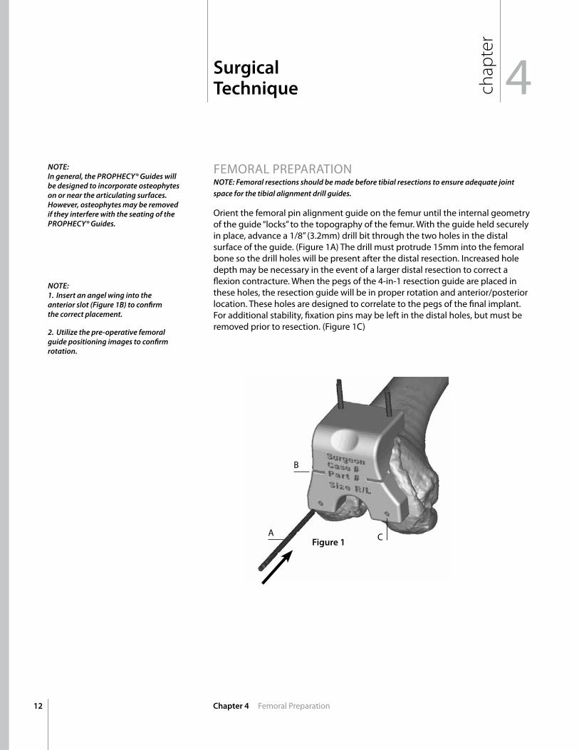
Orient the femoral pin alignment guide on the femur until the internal geometry of the guide “locks” to the topography of the femur. With the guide held securely in place, advance a 1/8” (3.2mm) drill bit through the two holes in the distal surface of the guide. (Figure 1A) The drill must protrude 15mm into the femoral bone so the drill holes will be present after the distal resection. Increased hole depth may be necessary in the event of a larger distal resection to correct a flexion contracture. When the pegs of the 4-in-1 resection guide are placed in these holes, the resection guide will be in proper rotation and anterior/posterior location. These holes are designed to correlate to the pegs of the final implant. For additional stability, fixation pins may be left in the distal holes, but must be removed prior to resection. (Figure 1C)
Surgical Technique 4
Chapter 4 Femoral Preparation
NOTE:In general, the PROPHECY® Guides will be designed to incorporate osteophytes on or near the articulating surfaces. However, osteophytes may be removed if they interfere with the seating of the PROPHECY® Guides.
NOTE: 1. Insert an angel wing into the anterior slot (Figure 1B) to confirm the correct placement.
2. Utilize the pre-operative femoral guide positioning images to confirm rotation.
Figure 1
B
A C
13Chapter 4 Femoral Preparation
NOTE: Threaded pins are not recommended for PROPHECY® Pin Alignment Guide fixation.Threaded pins may be difficult to drive through the holes in the guide.
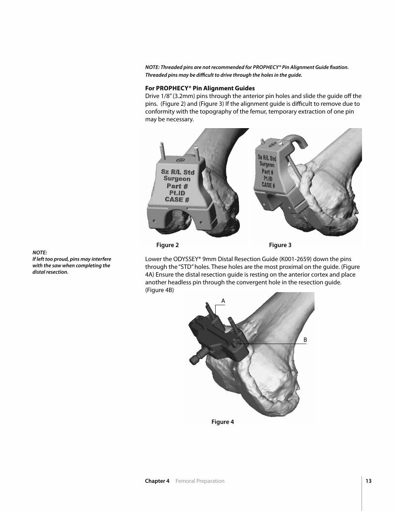
ForPROPHECY®PinAlignmentGuidesDrive 1/8” (3.2mm) pins through the anterior pin holes and slide the guide off the pins. (Figure 2) and (Figure 3) If the alignment guide is difficult to remove due to conformity with the topography of the femur, temporary extraction of one pin may be necessary.
NOTE:If left too proud, pins may interfere with the saw when completing the distal resection.
Lower the ODYSSEY® 9mm Distal Resection Guide (K001-2659) down the pins through the “STD” holes. These holes are the most proximal on the guide. (Figure 4A) Ensure the distal resection guide is resting on the anterior cortex and place another headless pin through the convergent hole in the resection guide. (Figure 4B)
Figure 2
Figure 4
Figure 3
A
B
14
A
B
matches implant width
Chapter 4 Femoral Preparation
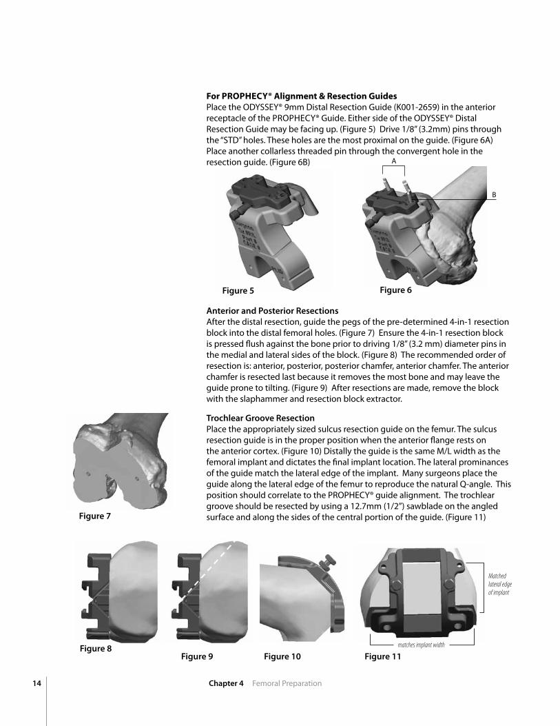
Anterior and Posterior ResectionsAfter the distal resection, guide the pegs of the pre-determined 4-in-1 resection block into the distal femoral holes. (Figure 7) Ensure the 4-in-1 resection block is pressed flush against the bone prior to driving 1/8” (3.2 mm) diameter pins in the medial and lateral sides of the block. (Figure 8) The recommended order of resection is: anterior, posterior, posterior chamfer, anterior chamfer. The anterior chamfer is resected last because it removes the most bone and may leave the guide prone to tilting. (Figure 9) After resections are made, remove the block with the slaphammer and resection block extractor.
Trochlear Groove ResectionPlace the appropriately sized sulcus resection guide on the femur. The sulcus resection guide is in the proper position when the anterior flange rests on the anterior cortex. (Figure 10) Distally the guide is the same M/L width as the femoral implant and dictates the final implant location. The lateral prominances of the guide match the lateral edge of the implant. Many surgeons place the guide along the lateral edge of the femur to reproduce the natural Q-angle. This position should correlate to the PROPHECY® guide alignment. The trochlear groove should be resected by using a 12.7mm (1/2”) sawblade on the angled surface and along the sides of the central portion of the guide. (Figure 11)
ForPROPHECY®Alignment&ResectionGuidesPlace the ODYSSEY® 9mm Distal Resection Guide (K001-2659) in the anterior receptacle of the PROPHECY® Guide. Either side of the ODYSSEY® Distal Resection Guide may be facing up. (Figure 5) Drive 1/8” (3.2mm) pins through the “STD” holes. These holes are the most proximal on the guide. (Figure 6A) Place another collarless threaded pin through the convergent hole in the resection guide. (Figure 6B)
Figure 5
Figure 7
Figure 8Figure 9
Figure 6
Figure 10 Figure 11
Matched lateral edge of implant
15Chapter 4 Tibial Preparation and Final Reduction
PROxIMAL TIBIAL RESECTIOnNOTE: The ODYSSEY® Tibial Resection Guides are designed for use with a 1.3 mm (.050”) thick saw blade.
NOTE:1. Utilize the alignment rod to confirm alignment.
2. Utilize the pre-operative tibial guide positioning images to confirm proper placement.
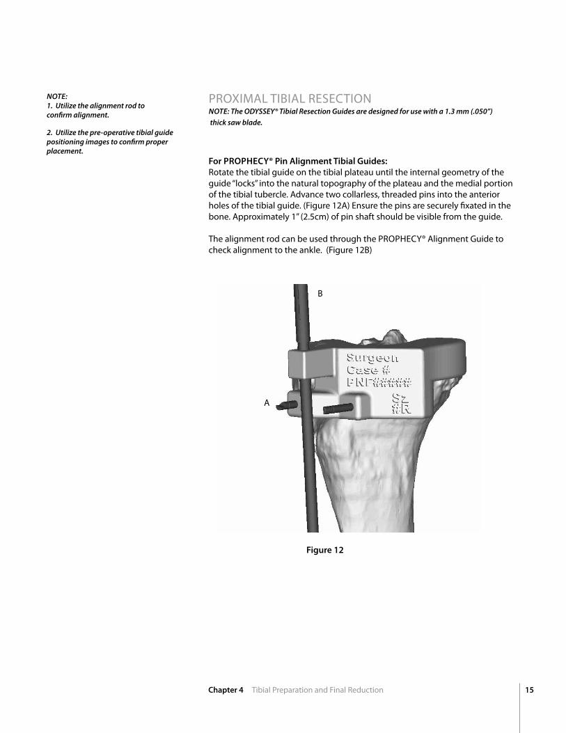
For PROPHECY® Pin Alignment Tibial Guides:Rotate the tibial guide on the tibial plateau until the internal geometry of the guide “locks” into the natural topography of the plateau and the medial portion of the tibial tubercle. Advance two collarless, threaded pins into the anterior holes of the tibial guide. (Figure 12A) Ensure the pins are securely fixated in the bone. Approximately 1” (2.5cm) of pin shaft should be visible from the guide. The alignment rod can be used through the PROPHECY® Alignment Guide to check alignment to the ankle. (Figure 12B)
Figure 12
B
A
16 Chapter 4 Tibia Preparation and Final Reduction
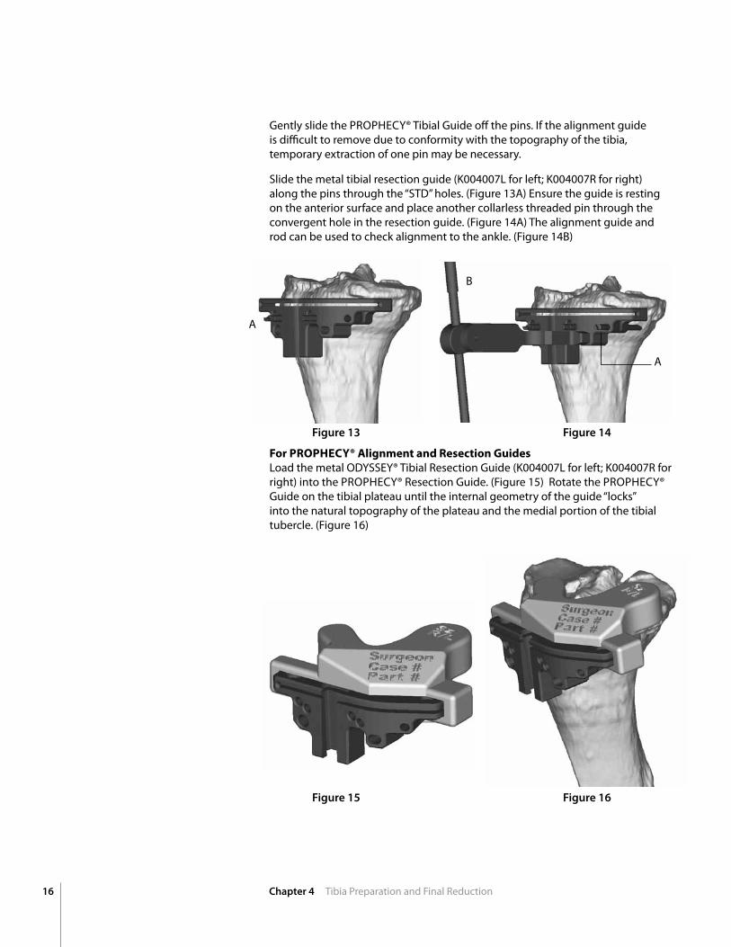
Gently slide the PROPHECY® Tibial Guide off the pins. If the alignment guide is difficult to remove due to conformity with the topography of the tibia, temporary extraction of one pin may be necessary.
Slide the metal tibial resection guide (K004007L for left; K004007R for right) along the pins through the “STD” holes. (Figure 13A) Ensure the guide is resting on the anterior surface and place another collarless threaded pin through the convergent hole in the resection guide. (Figure 14A) The alignment guide and rod can be used to check alignment to the ankle. (Figure 14B)
ForPROPHECY®AlignmentandResectionGuidesLoad the metal ODYSSEY® Tibial Resection Guide (K004007L for left; K004007R for right) into the PROPHECY® Resection Guide. (Figure 15) Rotate the PROPHECY® Guide on the tibial plateau until the internal geometry of the guide “locks” into the natural topography of the plateau and the medial portion of the tibial tubercle. (Figure 16)
Figure 13
Figure 15
Figure 14
Figure 16
A
A
B
17Chapter 4 Tibial Preparation and Final Reduction
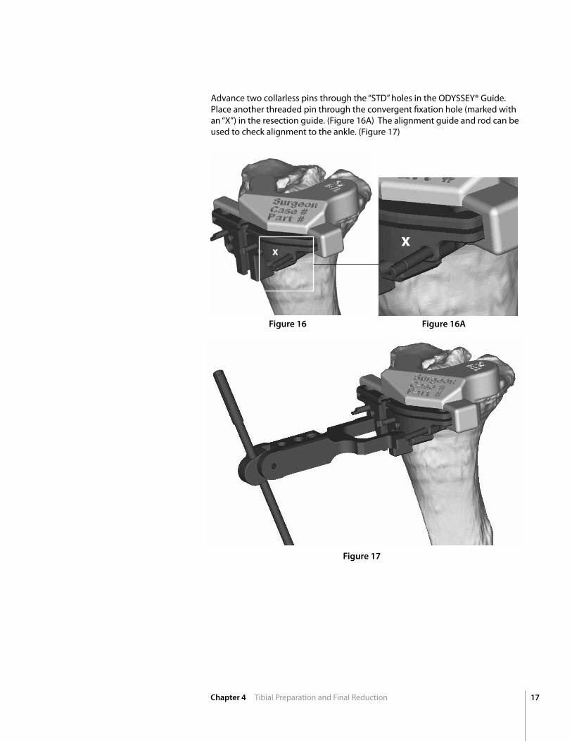
Advance two collarless pins through the “STD” holes in the ODYSSEY® Guide. Place another threaded pin through the convergent fixation hole (marked with an “x”) in the resection guide. (Figure 16A) The alignment guide and rod can be used to check alignment to the ankle. (Figure 17)
X
Figure 16 Figure 16A
Figure 17
X
18 Chapter 5 Tibial Keel Preparation
Tibial Preparation
NOTE: In all ADVANCE® Total Knees, with the exception of the ADVANCE® Double-High Knee, the tibial insert trial size must match the femoral trial size. There are two tibial base trial sizes that can be used with any one size femoral trial. For example a size 3 femoral trial can be used with either a size 3 or 3+ tibial trial base. When using the ADVANCE® Double-High insert trial, a femoral trial one size greater than the tibial insert trial may be utilized. For example, a size 3 ADVANCE® Double-High insert trial may be used with a size 3 or 4 femoral trial and a size 3 or 3+ tibial base trial.
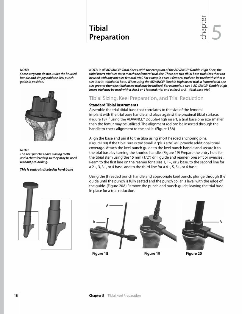
Tibial Sizing, Keel Preparation, and Trial Reduction StandardTibialInstrumentsAssemble the trial tibial base that correlates to the size of the femoral implant with the trial base handle and place against the proximal tibial surface. (Figure 18) If using the ADVAnCE® Double-High insert, a trial base one size smaller than the femur may be utilized. The alignment rod can be inserted through the handle to check alignment to the ankle. (Figure 18A) Align the base and pin it to the tibia using short headed anchoring pins. (Figure18B) If the tibial size is too small, a “plus size” will provide additional tibial coverage. Attach the keel punch guide to the keel punch handle and secure it to the trial base by turning the knurled handle. (Figure 19) Prepare the entry hole for the tibial stem using the 15 mm (1/2”) drill guide and reamer (press-fit or oversize). Ream to the first line on the reamer for a size 1, 1+, or 2 base, to the second line for a 2+, 3, 3+, or 4 base, and to the third line for a 4+, 5, 5+, or 6 base. Using the threaded punch handle and appropriate keel punch, plunge through the guide until the punch is fully seated and the punch collar is level with the edge of the guide. (Figure 20A) Remove the punch and punch guide; leaving the trial base in place for a trial reduction.
NOTE:Some surgeons do not utilize the knurled handle and simply hold the keel punch guide in position.
NOTE:The keel punches have cutting teeth and a chamfered tip so they may be used without pre-drilling.
This is contraindicated in hard bone
Figure 18 Figure 19 Figure 20
A
B A
chap
ter
5
19Chapter 5 Tibial Keel Preparation
BIOFOAM® Metal-Style InstrumentsAfter the proximal tibial resection has been made, select the proper tibial base trials, keel punch guide, reamer, and keel punch. Table 2 should be used to determine the sizing compatibility of the instrumentation.
Table 2 | Instrument Sizing Matrix
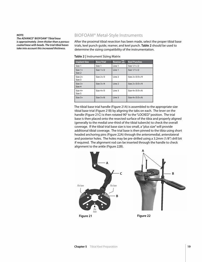
The tibial base trial handle (Figure 21A) is assembled to the appropriate size tibial base trial (Figure 21B) by aligning the tabs on each. The lever on the handle (Figure 21C) is then rotated 90° to the “LOCKED” position. The trial base is then placed onto the resected surface of the tibia and properly aligned (generally to the medial one-third of the tibial tubercle) to check the overall coverage. If the tibial trial base size is too small, a “plus size” will provide additional tibial coverage. The trial base is then pinned to the tibia using short headed anchoring pins (Figure 22A) through the anteromedial, anterolateral and posterior holes. The holes may be pre-drilled using a 3.2mm (1/8”) drill bit if required. The alignment rod can be inserted through the handle to check alignment to the ankle (Figure 22B).
Figure 22Figure 21
A
B
C B
A
ImplantSize BaseTrial Reamer KeelPunches
Size 1 Size 1 Line 1 Size 1/1+/2
Size 1+ Size 2
Size 1+/2 Line 1 Size 1/1+/2
Size 2+ Size 3
Size 2+/3 Line 2 Size 2+/3/3+/4
Size 3+ Size 4
Size 3+/4 Line 2 Size 2+/3/3+/4
Size 4+ Size 5
Size 4+/5 Line 3 Size 4+/5/5+/6
Size 5+ Size 5+/6 Line 3 Size 4+/5/5+/6
NOTE: The ADVANCE® BIOFOAM® Tibial baseis approximately .5mm thicker than a porous-coated base with beads. The trial tibial bases take into account this increased thickness.
Pin here Pin here
Pin here
FIG24A
20 Chapter 5 Tibial Keel Preparation
Align the four spikes on the keel punch guide with the corresponding holes on the trial base and impact the guide with a mallet until flush with the surface of the trial base. (Figure 23)
The reamer can be used to prepare the medullary canal if needed. Referring to Table 2, ream through the keel punch guide to the appropriate line indicated on the reamer. (Figure 24A) A 3.2mm drill bit may be used to prepare for the spikes on the implant as well (Figure 25) if utilizing a BIOFOAM® Tibial Base
Figure 23 Figure 24
Figure 25
Drill for Spikes
NOTE:Some surgeons do not pin the base before utilizing the keel punch guide.
Line 3
Line 2
Line 1
Figure 24A
21Chapter 5 Tibial Keel Preparation
Assemble the appropriate size keel punch to the keel punch handle by pulling back on the trigger mechanism on the handle (Figure 26A) and inserting it into the opening on the punch. The keel punch handle is impacted with a mallet until fully seated and the bottom edge of the handle aligns with the top of the punch guide (Figure 27A). The handle is disassembled from the punch by pulling back on the trigger mechanism and the punch guide is removed with a slaphammer and hook (Figure 28). A trial reduction can then be performed with the femoral, tibial, and insert trial components. If desired, the lines on the anterior portion of the trial bases (Figure 29A) can be marked to aid with alignment of the tibial base component during implantation. After trialing, the punch handle is used to remove the punch and the headed pins are removed with the slaphammer.
Figure 26 Figure 27 Figure 29
A
Figure 28
AA
22 Chapter 5 Tibial Keel Preparation
To prevent bony impingement in deep flexion, the posterior condyle which will not be covered by the femoral component is removed with a curved osteotome. (Figure 30)
Patella Preparation NOTE: Recessed patellar instrumentation is also available. To use this instrumentation,see Part B of the Additional Information Section
With the leg extended, the patella is tilted to almost a 90º angle. The 8mm resection depth gauge is attached to the top of the resection guide with the lock screw. (Figure 31) Position the resection guide jaws parallel to the articular margin and securely clamp the guide to the bone; ensuring the gauge is contacting the apex of the articular surface. (Figure 31A) Remove the gauge and locking screw and make the patellar resection. (Figure 32) Attach the appropriate drill guide to the patellar clamp (Figure 33A). The drill guides have grooves on their surfaces indicating the patellar diameter options. The appropriate tri-peg or central peg reamer is used to prepare the peg hole(s).
NOTE:Instead of utilizing a clamp for patellar resection some surgeons prefer a non-instrumented technique. NOTE: The tri-peg patellae have the same peg locations between sizes and can be easily changed during trial reduction.
Figure 31 Figure 32 Figure 33
A
A
Figure30
23
chap
ter
Chapter 6 Trial Reduction and Implant Insertion
6Trial Reduction andImplant Insertion
TRIAL REDUCTIOn/IMPLAnT InSERTIOn NOTE: It is highly recommended to sacrifice the PCL when utilizing the ADVANCE® Medial-Pivot insert. For PCL-retention, the ADVANCE® Double-High Insert is available.
NOTE: In all ADVANCE® total knees, with the exception of the ADVANCE® Double-High Knee, the tibial insert size must match the femoral implant size (see Table 3). There are two tibial base sizes that can be used with any one size femoral component. For example a size 3 femoral implant can be used with either a size 3 or 3+ tibial base. (Figure 34) When using the ADVANCE® Double-High insert, a femoral component one size greater than the tibial insert may be utilized. For example, a size 3 ADVANCE® Double-High insert may be used with a size 3 or 4 femur and a size 3 or 3+ tibial base (see Table 4)
Medial-Pivot Traditional
PS
Double High
Femur Insert Tibia 1 1 1 or 1+ 2 2 2 or 2+ 3 3 3 or 3+ 4 4 4 or 4+ 5 5 5 or 5+ 6 6 6
Femur Insert Tibia 1 or 2 1 1 or 1+ 2 or 3 2 2 or 2+ 3 or 4 3 3 or 3+ 4 or 5 4 4 or 4+ 5 or 6 5 5 or 5+
Place the appropriate size femoral trial on the distal femur using the femoral impactor (Figure 35). Insert the trial insert of appropriate size and thickness onto the trial base and complete the trial reduction. If necessary, drill for the femoral implant fixation peg through the femoral trial implant using the 4.8mm (3/16”) drill bit. After the trial reduction is complete, remove the femoral trial with the slaphammer by sliding the disc extractor tip between the femoral condyles (Figure 36). During removal, keep one hand on the trial to control its extraction. Remove the short headed tibial fixation pins with the pin puller or slap hammer pin extractor.
3 BASE 3+ BASE
Table3 Table4
Figure34
Figure 35 Figure 36
24 Chapter 6 Trial Reduction and Implant Insertion
The recommended order for implantation is left to the discretion of the orthopaedic surgeon. Insert the femoral implant with the femoral impactor. Careshouldbetakentoensurethefemoralcomponentisnotforcedintoflexionbythedivergentanteriorflange.
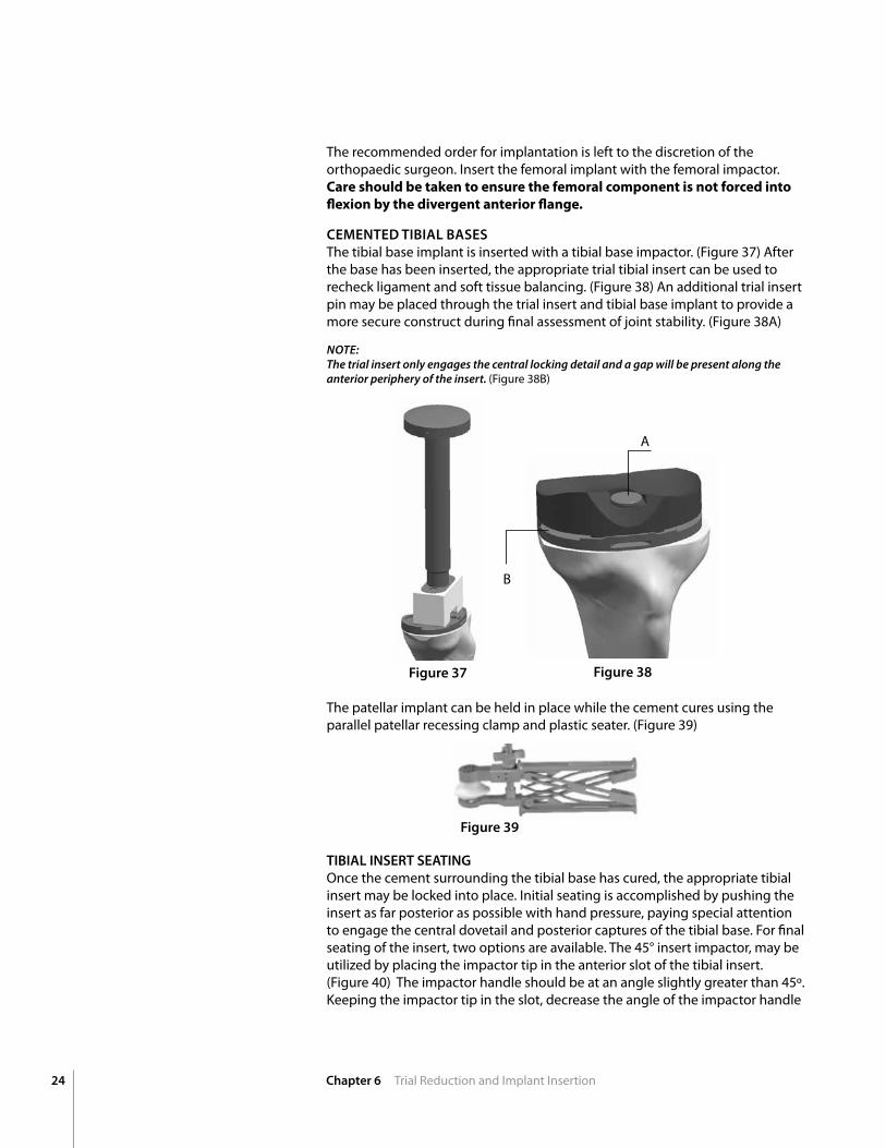
CEMEnTED TIBIAL BASESThe tibial base implant is inserted with a tibial base impactor. (Figure 37) After the base has been inserted, the appropriate trial tibial insert can be used to recheck ligament and soft tissue balancing. (Figure 38) An additional trial insert pin may be placed through the trial insert and tibial base implant to provide a more secure construct during final assessment of joint stability. (Figure 38A)
NOTE: The trial insert only engages the central locking detail and a gap will be present along the anterior periphery of the insert. (Figure 38B)
Figure 37 Figure 38
A
B
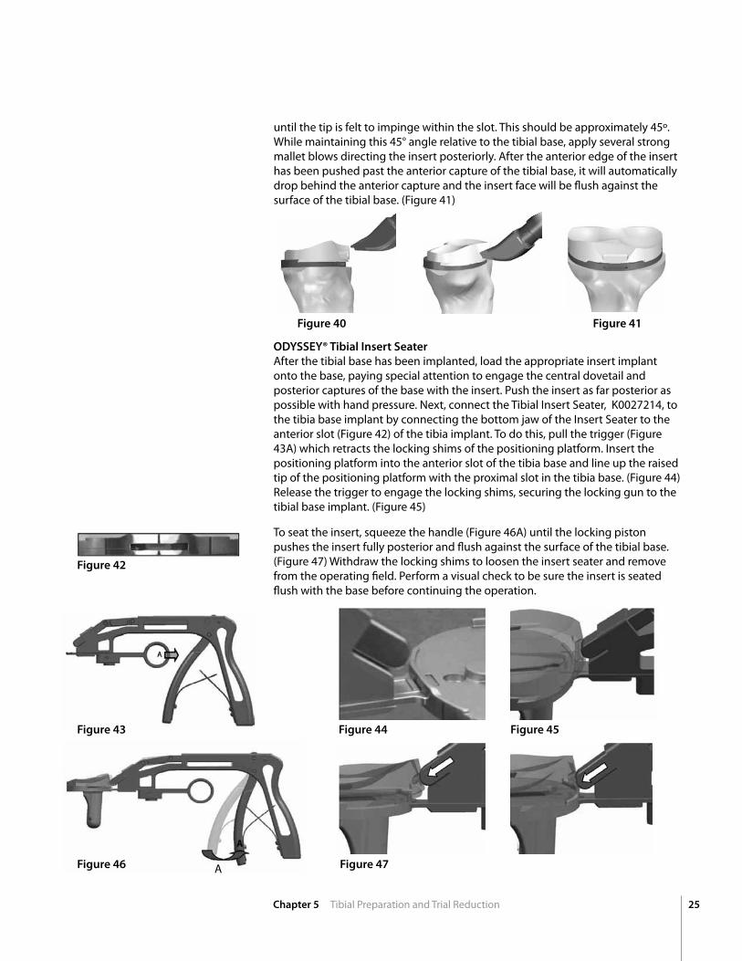
TIBIAL InSERT SEATInG Once the cement surrounding the tibial base has cured, the appropriate tibial insert may be locked into place. Initial seating is accomplished by pushing the insert as far posterior as possible with hand pressure, paying special attention to engage the central dovetail and posterior captures of the tibial base. For final seating of the insert, two options are available. The 45° insert impactor, may be utilized by placing the impactor tip in the anterior slot of the tibial insert. (Figure 40) The impactor handle should be at an angle slightly greater than 45º. Keeping the impactor tip in the slot, decrease the angle of the impactor handle
The patellar implant can be held in place while the cement cures using the parallel patellar recessing clamp and plastic seater. (Figure 39)
Figure 39
25Chapter 5 Tibial Preparation and Trial Reduction
ODYSSEY® Tibial Insert Seater After the tibial base has been implanted, load the appropriate insert implant onto the base, paying special attention to engage the central dovetail and posterior captures of the base with the insert. Push the insert as far posterior as possible with hand pressure. next, connect the Tibial Insert Seater, K0027214, to the tibia base implant by connecting the bottom jaw of the Insert Seater to the anterior slot (Figure 42) of the tibia implant. To do this, pull the trigger (Figure 43A) which retracts the locking shims of the positioning platform. Insert the positioning platform into the anterior slot of the tibia base and line up the raised tip of the positioning platform with the proximal slot in the tibia base. (Figure 44) Release the trigger to engage the locking shims, securing the locking gun to the tibial base implant. (Figure 45)
To seat the insert, squeeze the handle (Figure 46A) until the locking piston pushes the insert fully posterior and flush against the surface of the tibial base. (Figure 47) Withdraw the locking shims to loosen the insert seater and remove from the operating field. Perform a visual check to be sure the insert is seated flush with the base before continuing the operation.
Figure 40
Figure 42
Figure 41
until the tip is felt to impinge within the slot. This should be approximately 45º. While maintaining this 45° angle relative to the tibial base, apply several strong mallet blows directing the insert posteriorly. After the anterior edge of the insert has been pushed past the anterior capture of the tibial base, it will automatically drop behind the anterior capture and the insert face will be flush against the surface of the tibial base. (Figure 41)
Figure 43
Figure 46 Figure 47
Figure 44 Figure 45
A
26
Add
ition
al
Info
rmat
ion
Chapter 6 Additional Information, Part A
Additional Information
Figure 48
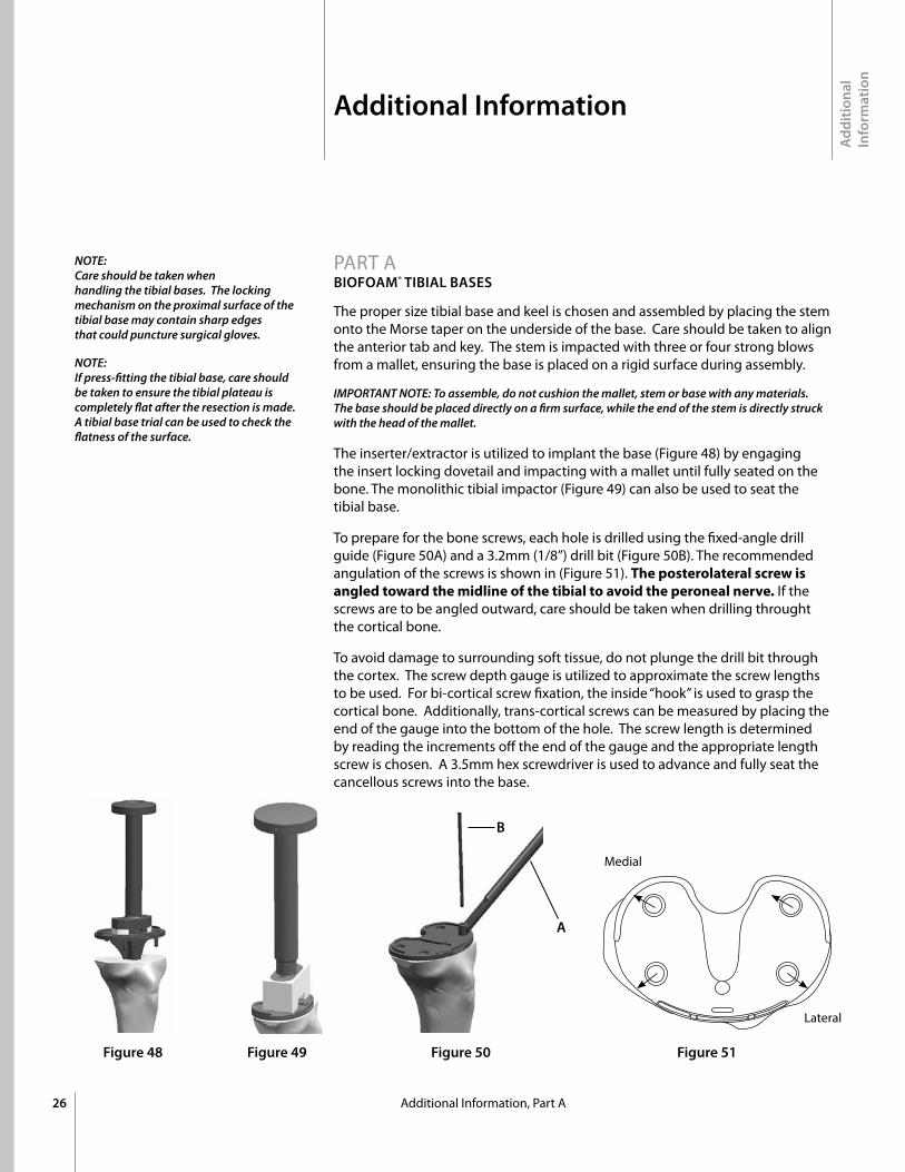
The proper size tibial base and keel is chosen and assembled by placing the stem onto the Morse taper on the underside of the base. Care should be taken to align the anterior tab and key. The stem is impacted with three or four strong blows from a mallet, ensuring the base is placed on a rigid surface during assembly.
IMPORTANT NOTE: To assemble, do not cushion the mallet, stem or base with any materials. The base should be placed directly on a firm surface, while the end of the stem is directly struck with the head of the mallet.
The inserter/extractor is utilized to implant the base (Figure 48) by engaging the insert locking dovetail and impacting with a mallet until fully seated on the bone. The monolithic tibial impactor (Figure 49) can also be used to seat the tibial base.
To prepare for the bone screws, each hole is drilled using the fixed-angle drill guide (Figure 50A) and a 3.2mm (1/8”) drill bit (Figure 50B). The recommended angulation of the screws is shown in (Figure 51). Theposterolateralscrewisangledtowardthemidlineofthetibialtoavoidtheperonealnerve. If the screws are to be angled outward, care should be taken when drilling throught the cortical bone.
To avoid damage to surrounding soft tissue, do not plunge the drill bit through the cortex. The screw depth gauge is utilized to approximate the screw lengths to be used. For bi-cortical screw fixation, the inside “hook” is used to grasp the cortical bone. Additionally, trans-cortical screws can be measured by placing the end of the gauge into the bottom of the hole. The screw length is determined by reading the increments off the end of the gauge and the appropriate length screw is chosen. A 3.5mm hex screwdriver is used to advance and fully seat the cancellous screws into the base.
Figure 49 Figure 50
A
B
Figure 51
Medial
Lateral
NOTE: Care should be taken when handling the tibial bases. The locking mechanism on the proximal surface of the tibial base may contain sharp edges that could puncture surgical gloves.
NOTE: If press-fitting the tibial base, care should be taken to ensure the tibial plateau is completely flat after the resection is made. A tibial base trial can be used to check the flatness of the surface.
PART A BIOFOAM® TIBIAL BASES
27
Additional Information
Add
ition
al
Info
rmat
ion
Chapter 6 Additional Information, Part B, C
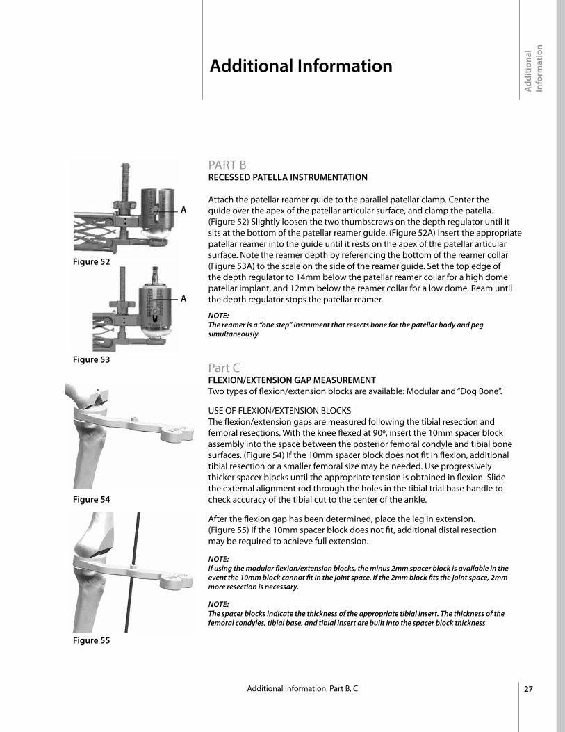
PART BRECESSED PATELLA InSTRUMEnTATIOn Attach the patellar reamer guide to the parallel patellar clamp. Center the guide over the apex of the patellar articular surface, and clamp the patella. (Figure 52) Slightly loosen the two thumbscrews on the depth regulator until it sits at the bottom of the patellar reamer guide. (Figure 52A) Insert the appropriate patellar reamer into the guide until it rests on the apex of the patellar articular surface. note the reamer depth by referencing the bottom of the reamer collar (Figure 53A) to the scale on the side of the reamer guide. Set the top edge of the depth regulator to 14mm below the patellar reamer collar for a high dome patellar implant, and 12mm below the reamer collar for a low dome. Ream until the depth regulator stops the patellar reamer.
NOTE: The reamer is a “one step” instrument that resects bone for the patellar body and peg simultaneously.
Part C FLEXIOn/EXTEnSIOn GAP MEASUREMEnT Two types of flexion/extension blocks are available: Modular and “Dog Bone”.
USE OF FLExIOn/ExTEnSIOn BLOCKS The flexion/extension gaps are measured following the tibial resection and femoral resections. With the knee flexed at 90º, insert the 10mm spacer block assembly into the space between the posterior femoral condyle and tibial bone surfaces. (Figure 54) If the 10mm spacer block does not fit in flexion, additional tibial resection or a smaller femoral size may be needed. Use progressively thicker spacer blocks until the appropriate tension is obtained in flexion. Slide the external alignment rod through the holes in the tibial trial base handle to check accuracy of the tibial cut to the center of the ankle.
After the flexion gap has been determined, place the leg in extension. (Figure 55) If the 10mm spacer block does not fit, additional distal resection may be required to achieve full extension.
NOTE:If using the modular flexion/extension blocks, the minus 2mm spacer block is available in the event the 10mm block cannot fit in the joint space. If the 2mm block fits the joint space, 2mm more resection is necessary.
NOTE:The spacer blocks indicate the thickness of the appropriate tibial insert. The thickness of the femoral condyles, tibial base, and tibial insert are built into the spacer block thickness
Figure 52
Figure 54
Figure 53
Figure 55
A
A
Add
ition
al
Info
rmat
ion
28 Chapter 6 Additional Information, Part D, E, F
Additional Information
Collared threaded or headed impaction pins are generally utilized for the 4-in-1 resection guides. Ensure the collared, threaded pins are not over-driven once the collar contacts the guide outrigger. If over-driven, the threaded pins will strip the bone and lose fixation.
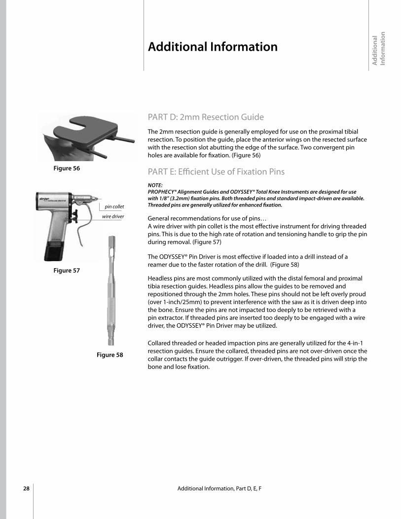
PART D: 2mm Resection Guide The 2mm resection guide is generally employed for use on the proximal tibial resection. To position the guide, place the anterior wings on the resected surface with the resection slot abutting the edge of the surface. Two convergent pin holes are available for fixation. (Figure 56)
PART E: Efficient Use of Fixation PinsNOTE:PROPHECY® Alignment Guides and ODYSSEY® Total Knee Instruments are designed for use with 1/8” (3.2mm) fixation pins. Both threaded pins and standard impact-driven are available. Threaded pins are generally utilized for enhanced fixation.
General recommendations for use of pins… A wire driver with pin collet is the most effective instrument for driving threaded pins. This is due to the high rate of rotation and tensioning handle to grip the pin during removal. (Figure 57)
The ODYSSEY® Pin Driver is most effective if loaded into a drill instead of a reamer due to the faster rotation of the drill. (Figure 58)
Headless pins are most commonly utilized with the distal femoral and proximal tibia resection guides. Headless pins allow the guides to be removed and repositioned through the 2mm holes. These pins should not be left overly proud (over 1-inch/25mm) to prevent interference with the saw as it is driven deep into the bone. Ensure the pins are not impacted too deeply to be retrieved with a pin extractor. If threaded pins are inserted too deeply to be engaged with a wire driver, the ODYSSEY® Pin Driver may be utilized.
Figure 56
Figure 57
Figure 58
pin collet
wire driver
29
Component Specifications
A B
26 8
29 8
32 8
35 8
38 10
41 11
Onlay All-poly Tri Peg
A
B (mm)
(mm)
A B
25 Low 7
25 High 9
28 Low 7
28 High 9
Recessed All-poly
A
B (mm)
(mm)
A B
32 8
35 8
38 10
41 11
Onlay All-poly Single Peg
A
B (mm)
(mm)
Component Specifications
30
Primary Pressfit Keels
SIZE A B C
1 60 41 34
1+ 65 44 34
2 65 44 34
2+ 70 48 41
3 70 48 41
3+ 75 51 41
4 75 51 41
4+ 80 54 49
5 80 54 49
5+ 85 58 49
SIZE A B C
1 60 41 47
1+ 65 44 47
2 65 44 47
2+ 70 48 47
3 70 48 47
3+ 75 51 47
4 75 51 47
4+ 80 54 47
5 80 54 47
5+ 85 58 47
Modular Pressfit Keels
C
BA
A
C
B
(mm)
(mm)
(mm) (mm)
(mm)
(mm)


™Trademarks and ®Registered marks of Wright Medical Technology, Inc. ©2010 Wright Medical Technology, Inc. All Rights Reserved. MK 623-1008 R910
Wright Medical Technology, Inc.5677 Airline RoadArlington, Tn USA 38002901.867.9971 phone800.238.7188 toll-freewww.wmt.com
Wright Medical EMEAKrijgsman 11 1186 DM Amstelveen The netherlands 011.31.20.545.0100 www.wmt-emea.com