Embed Size (px)
Citation preview
133
Scan Converting Extruded Lines at Ultra High Definition
Philip Willis and Geoff Watters
A h C i
We consider the problem of generating freehand raster graphics pictures at ultra high definition (typically one gigapixel per picture) by scan converting extruded lines. We describe a fast scan conversion algorithm which is linear in final resolution and which incorporates a number of features to ensure high efficiency. Sample pictures and corresponding performance figures are included.
1. Introduction With the increased popularity of raster displays, efficient scan conversion of vectors to raster format became a requirement of most graphics systems. Bresenham's incremental techniques have become the standard way of scan converting straight lines' and cir- cular arcs? while other conics have also been produced in an efficient manner?
Laser printers too are raster devices. The higher resolution models have a bandwidth considerably in excess of broadcast television and so here too efficient algorithms have to be incorporated. The application of such printers has spurred further interest in scan con- verting a wider class of shapes.
Colour printing has in recent years been dom- inated by digital process technology in which the opera- tor is presented with a colour image on a raster display. The image can then be manipulated electronically in the digital domain before the data is finally used to engrave a printing plate for reproduction. Print quality can be very high with resolutions from 100 to 4,000 samples per inch.
There is therefore a pronounced tendency for hardcopy resolution to increase faster than display resolution, so the problem of scan conversion is at its most acute when it is being performed for a printing unit rather than for a display. Hardcopy also
This papa was presented at the EUROGRAPHICS (UK) Conference, Norwich, April 13-15 1987
School of Mathematical Sciences, university of Bath Claverton Down Bath, Avon, BA2 7AY England
corresponds to the highest amount of data because this is the stage at which the rasterized image is fully real- ized. To emphasise this point, consider a picture eight inches square at 4,096 points per inch. This will con- tain 1 giga samples. For a colour image a sample will be upto 24 bits, so each picture will occupy three giga- bytes of memory.
We have therefore set ourselves the task of scan converting at ultra-high resolution in a very efficient manner. E l s e ~ h e r e ~ . ~ we describe a paint program specifically designed to originate pictures as extruded line segments. Combining this with the scan convertor we achieve a system allowing freehand drawing on a conventional display yet st i l l capable of reproduction at ultra high resolution.
This paper describes in detail the scan conver- sion algorithm. We start by giving an overview of our approach and explaining the desired features. Next we describe the overall management of the algorithm together with the main data structures. We then con- sider the detailed problem of scan converting particular extruded shapes. Finally we show some pictures and give the timings for them.
2. CeneralApproacb Given a Iarge number of extruded h e segments with colour, thickness and shape our basic task is to produce a scan-ordered picture. ' To constrain the range of extruded shapes we choose to use only square and circular brushes, but we permit a range of sizes. Each brush stroke is thus a straight segment with definite colour, thickness and shaped ends. For simplicity we maintain a catalogue of the range of brushes offered and each of them has a unique identity code. We can thus classify each brush stroke as a record:
colour brushcode xstart,ystart xend,yend
/ * colour of the paint or ink */ / * size and shape of the brush */ / * one end of the segment */ / * the other end of the segment */
These segments are represented in the screen coordinate system, so that segments which are joined on the screen will indeed be joined in the internal representation.
A picture 6le on disk thus consists of a large
North-Holland computer Graphics Forum 6 (1987) 133-140
134 P. Willis e t al. 1 Scan Converting Exvuded Lines
number of such records with freehand curves being broken into many straight segments by the sampling rate of the data tablet used to originate the picture. These records will naturally be placed in the file in time sequence and so later records may correspond to seg- ments which overwrite earlier ones. Overwriting may take place many times and in extreme cases an early record may make no contribution at all to the 6nal ras- ter picture, having been completely over-painted. This is an acute problem with paint programs because the natural mode of use commonly leads to a high degree of overpainting. At the very high resolutions which we are considering it becomes imperative to minimise such inefficiencies.
Accordingly we use a method which allows us to scananvert in reverse time order so that we avoid repeatedly updating any region of the picture which already has useful data in it. In essence we apply the top layer of paint Erst and then prohibit the applica- tion of layers “underneath” because they will never be seen. The result is analogous to a reverse painters’ algorithm for hidden surface removal and has some parallels to the latter.
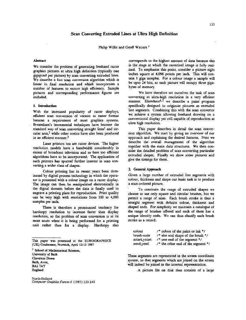
Scan converting a particular line segment proceeds in three stages. To see why, consider Figure 1 which represents a circular brush being extruded along a straight path. Given a scan line passing through this extruded shape we need to calculate the intersections of the scan line with both the left and right edges of the shape. Once we know all such intersections on the current scan line and the sequence in which they were painted we can deduce the colour of any named scan line pixel. Scan conversion of that scan line is then complete and we can consider the next one.
Figure 1. Extruding a circular brush
In Figure 1 it can be seen that we can usefully break the left (or right) edge into three sections. There are two shaped end pieces and an intepediate stright edge. Generally the two shaped end pieces wiU need individual conversion and the central straight section can always be converted by the Bresenham method.’
Figure 2. Extruding a square brush
The Bresenham increments are precalculated and stored in the data structure used by the scan convertor. The orientation of the segments affects the way the three sections are used: a horizontal segment is a degenerate case, having no Bre.senham region; with square brushes there are only two regions on any edge, but which they are depends both on the edge and the slope of the seg- ment (Figure 2). However this can also be precom- puted and the necessary information placed in the data structure and so a simple test of y coordinate deter- mines which section to use.
What results is a method of incrementally calcu- lating each edge of all extruded segments, the calcula- tion switching between the three regions according to y coordinate. We now describe the algorithm and the features that permit very high definitions to be achieved.
3. Management of the Scan Conversion We use a scan line approach, working incrementally up the picture. The method starts with a time-ordered sequence of records of the kind described in the previ- ous section. In what follows we assume without loss of generality that ystart Syend.
We note Erst that the coordinate values will have been recorded at screen resolution but that we will in general be producing a picture at a different (higher) resolution. We thus calculate a scale factor and use this to convert each record to the higher resolution tar- get coordinate system.
3.1. Bucket Sort
The scaled records are bucket-sorted at the target reso- lution. That is, for a target picture of 4096 by 4096 pixels we create 4096 buckets each being a linked list. Every record is placed in the list which corresponds to its lowest y value, yrnin. To determine ymin, we use ystart reduced by an amount corresponding to the brush radius, easily deduced from prior knowledge of the brush type and the scale factor. S d a r l y we will
P. Willis et al. 1 Scan Converting Extruded Lines 135
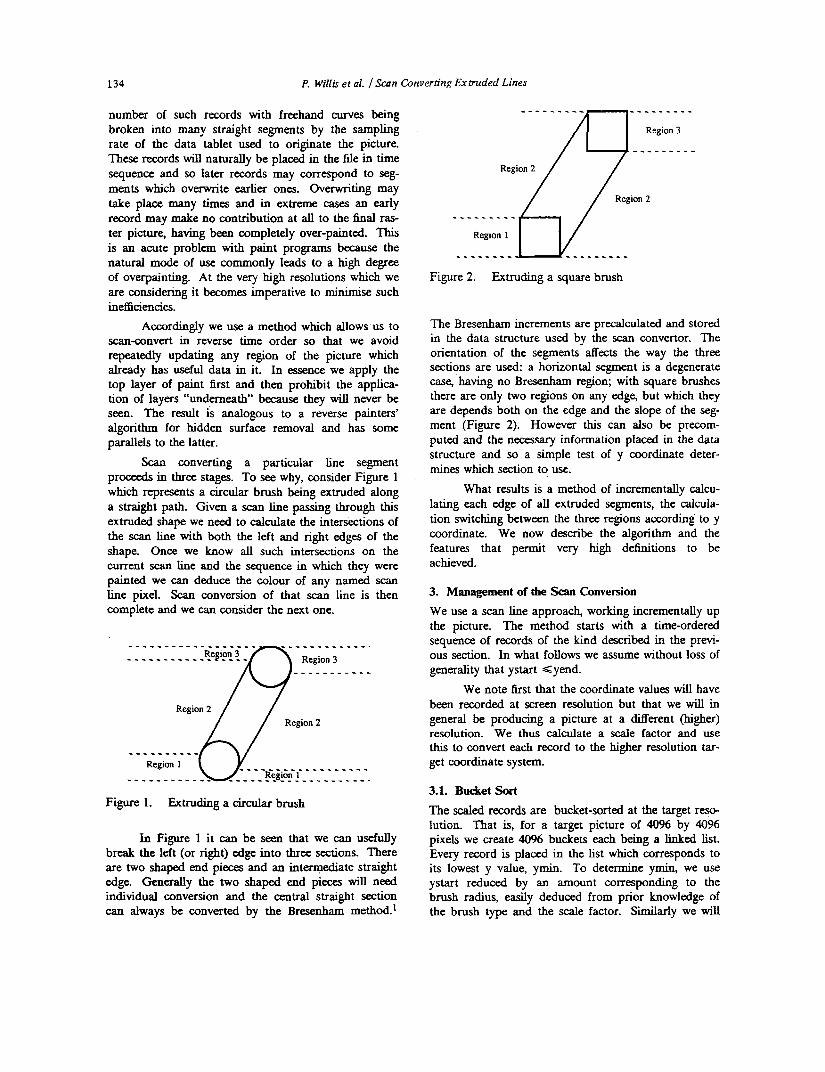
need ymax, the highest y value covered by the segment. This is yend plus the scaled radius. Figure 3 shows the relationship between these quantities.
- ymax
‘yend
Figure 3. segment
Parameters used to define the extent of a
Figure 4. Main data structure
The lists are constructed in inverse time order; that is records are added by insertion at the start of the list. Hence, when traversing the list from the head, the most recent record will be met fust. In order to In our case, x and y are constrained to fall on an integer grid and we also have an integer brush radius R. In general we wil l only be able to produce approxi- mate solutions to the circle equation:
x 2 + y 2 - R 2 ZfI (1)
For a given y, y 2 - R 2 is constant and so (1) may be written:
x 2 + c = o (2) Thus, for a given y, as x increases from 0, (2) increases from being negative to being positive and the change of sign occurs as x passes the circular arc. If (2) has value zero, this corresponds to x on the circle. If not then whichever of the two values around zero (one negative, one positive) has minimum absolute value is the required x, because this is closest to the circle.
This is satisfactory for those octants where x varies more rapidly than y, but does not give connected arcs elsewhere. Hence, for those cases, we replace equation (2) with the symmetric case in y:
y * + d z O (3)
Hence we can convert a circle using integer arith- metic incrementally. The inner loop of the calculation is efficient because it is essentially incrementing an integer quantity.
We are not converting an entire circle and so need to know where the straight edge of the extruded segment is tangential to the circle. This calculation is performed only once for a given segment, the remaining three points (two edges tangential to two circles) being deduced by symmetry.
For extra efficiency we use a look-up table to generate the squares. This is possible because we know the range of brush sizes. The gain from this is however modest and it could be omitted. Similarly, there is coherence around the arc so it is not necessary to reset x to zero for each scan line. Instead, x can commence from its previous value, being incremented or decre- mented according to the octant. Finally, although we cannot use rotational symmetry, we can use left-right symmetry. When both the left and right intercepts are with the circular ends of a segment we calculate one and deduce the second by left-right reflection about the centre of the circle.
3.4. Identify Unpainted pivels and Update Central to the algorithm is a method of identifying which pixels have already had their colour determined. It is this which allows us to avoid repeatedly writing the same pixel. We refer to any pixel which has already been coloured as foreground. Similarly, any pixel as yet uncoloured is called background. Only background may be overpainted.
First consider the scan line before any of its pix- els are set. In this case all pixels will be background and so all pixels are available for painting. Now sup- pose we have found the left and right intercepts of the first line segment in the Active List. If we were to out- put to a pixel line buffer we would fill all pixels between these two intercepts with the appropriate colour. When the pixels are set between these two lim- its, the scan line is generally split into three spans:-
x x x . . . x x c c c c x x . . . x x x
x = background d o u r c = segmentcolour
136 P. Willis et a1 1 Scan Converting Extruded Lines
The spans at either end remain the background colour and so are still available for painting, whilst the span in the middle is now colour C and so is not avail- able. As more of the segments on this scan line are similarly processed more and more spans will appear. A simple solution to our overpainting problem would be to reserve a special code for the background d o u r and then to read each pixel immediately before attempting to write it. Writing would be only allowed if the pixel were background colour. However this method requires every pixel to be read every time an overwrite is attempted. Hence it is inherently slow because updating a single span of n pixels always requires n reads. Further, the time taken to compute the picture would increase with the total number of pixels in the final image, giving a performance which, would degrade as the square of the resolution.
Therefore we introduce a dynamic structure, the Span List, to represent the foreground spans in a scan line, thereby also disposing of the need for a pixel buffer. This is a linked list of items representing hor- izontal runs of colour. Initially the list is empty (all background).
As conversion of a given scan line proceeds, more items enter the list. When two spans are adjacent they are coalesced to form a larger span. Of course some spans will consist of several colours, where adja- cent spans of Merent colour have been coalesced. Therefore each span is itself represented as a linked list, the Colour List, each element of which gives the colour and number of pixels of that colour. Occasionally two coalesced spans will be of identical colour and we can then replace the pair of records with a single record covering the entire span. (In practice we only do this if the records are part of the same sweep of the brush, so that we can use the convertor on pictures which maintain this order throughout subsequent processing each record is given a time sequence number. The bucket lists are entered via an array of head pointers, one for each list. Figure 4 shows the structure at this stage.
3.2 Corstruct and Maintain an Active List An Active List is initialised by setting a pointer to the head of the first bucket list. The first scan line can now be scan converted by considering only those items in the Active List. To convert the second and subsequent scan lines the Active List is incrementally updated in two ways. First, all records corresponding to segments below the current scan line have to be removed. Such records will have become fully converted on the previ- ous scan line. Records which need removing are identified by testing that their p a x entry is less than the y value of the current scan line. Second, the Bucket
List of the new current scan line has to be merged with the Active List to produce the new Active List (still in inverse time order). Such newly-merged records are about to start conversion. In practice both of these are performed on a single pass through the list, for speed. Bucket Lists below the current y value are no longer needed and hence we can construct the Active List using the same pointer field that is used to form the Bucket Lists, thereby saving on storage. Where the data is appropriate, this also allows us to merge com- plete sections of a Bucket List into the Active List, increasing efficiency. Finally, the Active List contains, by definition, only those records which actually inter- sect the current scan line. In a freehand drawing most line segments are short so only a small fraction of them will be in the Active List, greatly improving efficiency of the actual conversion. The use of bucket sort and an incrementally updated Active List first found com- puter graphics application to hidden surface removal? In our case time replaces depth as the sort key within a bucket and, having the records in time order to start with, there is no computation needed to maintain this order.
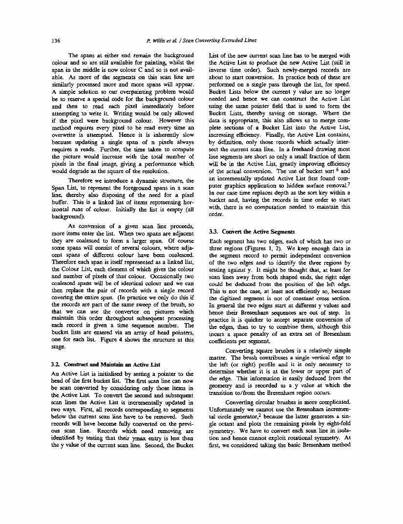
33. Convert the Active Segments Each segment has two edges, each of which has two or three regions (Figures 1, 2). We keep enough data in the segment record to permit independent conversion of the two edges and to identify the three regions by testing against y. It might be thought that, at least for scan lines away from both shaped ends, the right edge could be deduced from the position of the left edge. This i s not the case, at least not efficiently so, because the digitized segment is not of constant cross section. In general the two edges start at Werent y values and hence their Bresenham sequences are out of step. In practice it is quicker to accept separate conversion of the edges, than to try to combine them, although this incurs a space penalty of an extra set of Bresenham
Converting square brushes is a relatively simple matter. The brush contributes a single vertical edge to the left (or right) prolile and it is only necessary to determine whether it is at the lower or upper part of the edge. This information is easily deduced from the geometry and is recorded as a y value at which the transition to/from the Bresenham region cccurs.
Converting circular brushes is more complicated. Unfortunately we cannot use the Bresenham incremen- tal circle generator: because the latter generates a sin- gle octant and plots the remaining pixels by eight-fold symmetry. We have to convert each scan line in isola- tion and hence Cannot exploit rotational symmetry. At first, we considered taking the basic Bresenham method
coefficients per segment.
P, Willis et d /Scan Converting Extruded Lines 137
and re-initialiskg it whenever the conversion entered a new octant. This proved to be too complicated, essen- t idy because a radial line at 45 degrees (that is, the boundary between two octants) might or might not pass through a pixel on the circumference, requiring tests for special cases. Instead, we calculate the nearest pixel to the actual path of the circular arc using a related method.
To understand our method, consider a true circle drawn on top of an integer grid of points. The grid corresponds to the centres of the pixels. Suppose we know that a given horizontal scan line on the grid intersects the circle somewhere and we wish to locate the x coordinate of the leftmost intersection. We can do this by starting at a gnd point well to the left and evaluating the equation to the circle. The result wil l be negative, because we have chosen a point outside the circle. (It would be positive inside the circle and zero on the boundary of the circle). Now we move right to the next grid point and evaluate the equation again. The result will still be negative, but less so. We keep moving right until we futd a grid point which evaluates to a positive result. This grid point and its predecessor straddle the circle, one point being inside or on the cir- cle, one point outside. Whichever of these two pixels is closer to the circle is selected and illuminated. If we now wish to calculate the correct pixel on the next scan line we need not start so far to the left because we know that it will be close to the current one. We there- fore seek it nearby, knowing which octant we are gen- erating.
The method can be explained in detail by con- sidering the equation to a circle centred on the origin in the form:
x2 + y 2 = R 2
incorporate infilling. Details of this are beyond the scope of the present paper.)
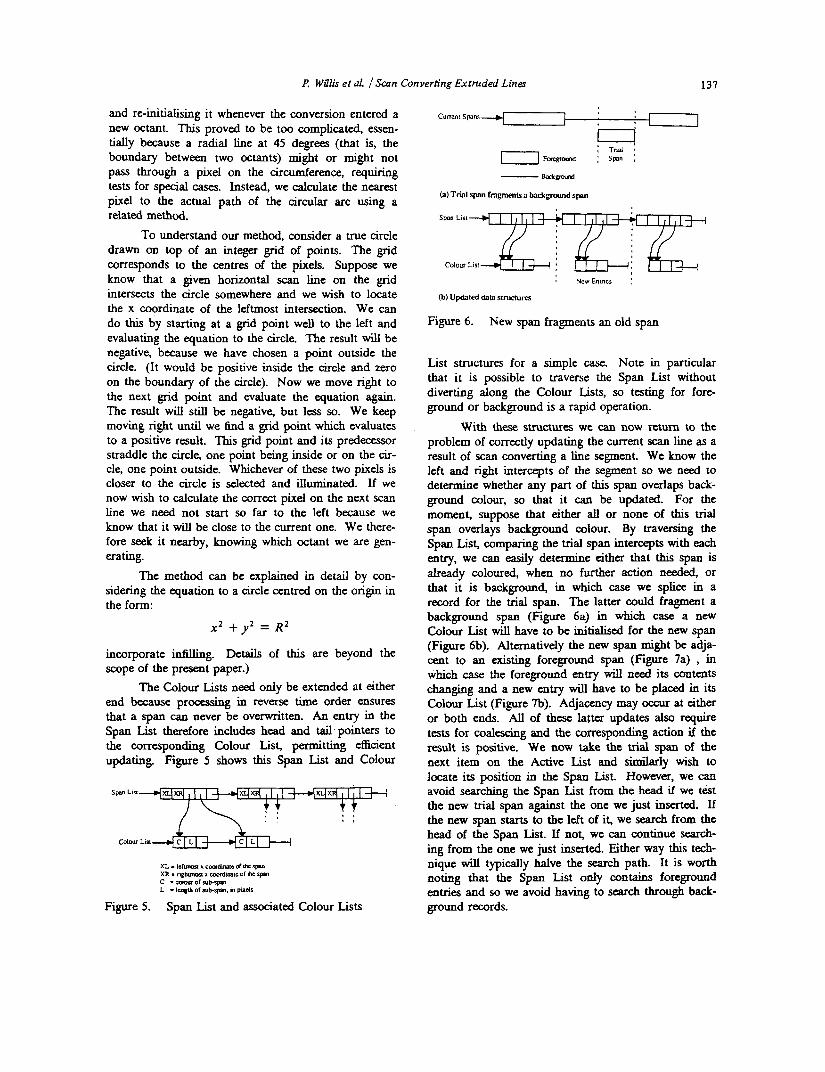
The Colour Lists need only be extended at either end because processing in reverse time order ensures that a span can never be overwritten. An entry in the Span List therefore includes head and tail.pointers to the corresponding Colour List, permitting efficient updating. Figure 5 shows this Span List and Colour
XL - I d u r n a x C d l w c Oflkrpm
c - c d c u f o f s u L l - ~ XR - nghUnoP 1 smdinslo of Ihs rpm
L - lcnglh of rub*. m pudr
Figure 5 . Span List and associated Colour Lists
I F?
New Enlricr :
Figure 6. New span fragments an old span
List structures for a simple case. Note in particular that it is possible to traverse the Span List without diverting along the Colour Lists, so testing for fore- ground or background is a rapid operation.
With these structures we can now return to the problem of correctly updating the current scan line as a result of scan converting a line segment. We know the left and right intercepts of the segment so we need to determine whether any part of this span overlaps back- ground colour, so that it car^ be updated. For the moment, suppose that either all or none of this trial span overlays background colour. By traversing the Span List, comparing the trial span intercepts with each entry, we can easily determine either that this span is already coloured, when no further action needed, or that it is background, in which case we splice in a record for the trial span. The latter could fragment a background span (Figure 6a) in which case a new Colour List wil l have to be initialised for the new span (Figure 6b). Alternatively the new span might be adja- cent to an existing foreground span (Figure 7a) , in which case the foreground entry will need its contents changing and a new entry wiU have to be placed in its Colour List (Figure 7b). Adjacency may occu at either or both ends. AU of these latter updates also require tests for coalescing and the corresponding action if the result is positive. We now take the trial span of the next item on the Active List and similariy wish to locate its position in the Span List. However, we can avoid searching the Span List from the head if we test the new trial span against the one we just inserted. If the new span starts to the left of it, we search from the head of the Span List. If not, we can continue search- ing from the one we just inserted. Either way this tech- nique will typically halve the search path. It is worth noting that the Span List only contains foreground entries and so we avoid having to search through back- ground records.
138 P. Will& et al. f Scan Converting Extruded Lines
Scale factor Load the input file
Currcnt Spans
4 8
13.6 13.6
(a) Trial span adjamt to P fwcgruund span
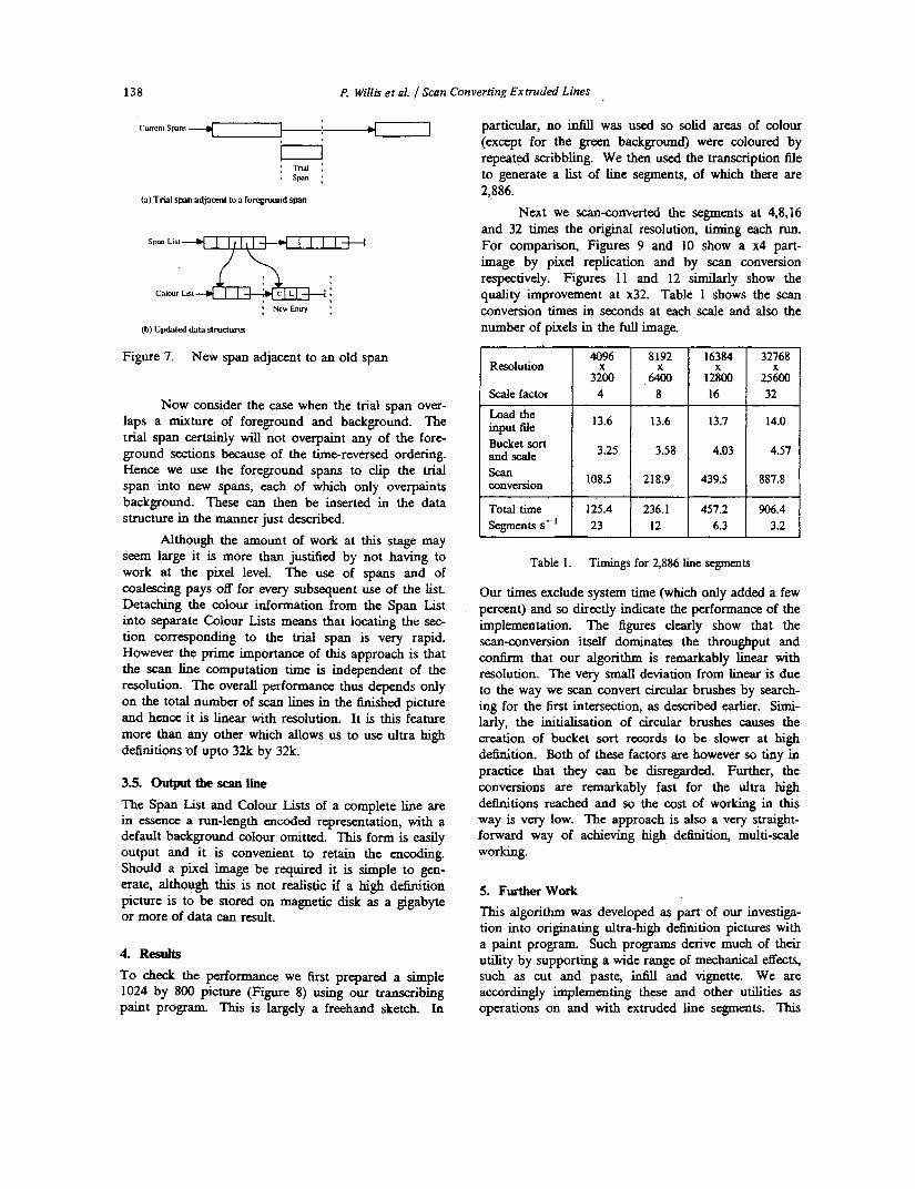
particular, no infill was used so solid areas of colour (except for the green background) were coloured by repeated scribbling. We then used the transcription file to generate a list of line segments, of which there are 2,886.
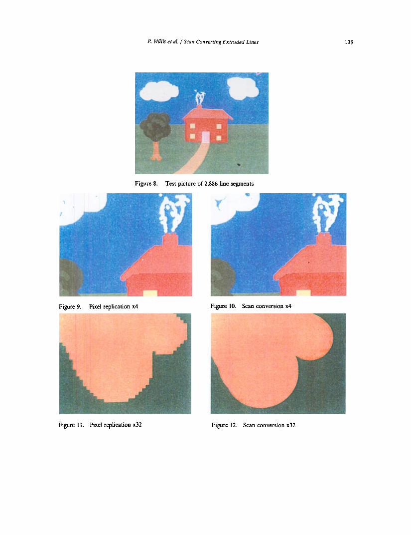
Next we scananverted the segments at 4,8,16 and 32 times the original resolution, timing each run. For comparison, Figures 9 and 10 show a x4 part- image by pixel replication and by scan conversion respectively. Figures 11 and 12 similarly show the quality improvement at x32. Table 1 shows the scan conversion times in seconds at each scale and also the number of pixels in the full image.
Figure 7. New span adjacent to an old span
Now consider the case when the trial span over- laps a mixture of foreground and background. The trial span certainly will not overpaint any of the fore- ground sections because of the time-reversed ordering. Hence we use the foreground spans to clip the trial span into new spans, each of which only overpaints background. These can then be inserted in the data structure in the manner just described.
Although the amount of work at this stage may seem large it is more than justified by not having to work at the pixel level. The use of spans and of coalescing pays off for every subsequent use of the list. Detaching the colour information from the Span List into separate Colour Lists means that locating the sec- tion corresponding to the trial span is very rapid. However the prime importance of this approach is that the scan line computation time is independent of the resolution. The overall performance thus depends only on the total number of scan lines in the finished picture and hence it is linear with resolution. It is this feature more than any other which allows us to use ultra high definitions -of upto 32k by 32k.
3.5. output tile scan lii
The Span List and Colour Lists of a complete line are in essence a run-length encoded representation, with a default background colour omitted. This form is easily output and it is convenient to retain the encoding. Should a pixel image be required it is simple to gen- erate, although this is not realistic if a high definition picture is to be stored on magnetic disk as a gigabyte or more of data can result.
4. Results To check the performance we first prepared a simple 1024 by 800 picture (Figure 8) using our transcribing paint program. This is largely a freehand sketch. In
Resolution
I 3.25 I 3.58 Bucket sort I and scale
1 Zersion 1 108.5 I 218.9
Total time 125.4 236.1 1 Segmentss-' 1 23 I 12 I
4.03 4.57
Table 1. Timings for 2,886 line segments
Our times exclude system time (which only added a few percent) and so directly indicate the performance of the implementation. The figures clearly show that the scananversion itself dominates the throughput and confirm that our algorithm is remarkably linear with resolution. The very small deviation from linear is due to the way we scan convert circular brushes by search- ing for the first intersection, as described earlier. Simi- larly, the initialisation of circular brushes causes the creation of bucket sort records to be slower at high deiinition. Both of these factors are however so tiny in practice that they can be disregarded. Further, the conversions are remarkably fast for the ultra high definitions reached and so the cost of working in this way is very low. The approach is also a very straight- forward way of achieving high definition, multi-scale working.
5. Furtherwork This algorithm was developed as part of our investiga- tion into originating ultra-high definition pictures with a paint program. Such programs derive much of their utility by supporting a wide range of mechanical effects, such as cut and paste, infill and vignette. We are accordingly implementing these and other utilities as operations on and with extruded line segments. This
P. Willis et al. f Scan Converting Extruded Lines 139
Figure 8. Test picture of 2,886 line segments
Figure 9. Pixel replication x4 Figure 10. Scan conversion x4
Figure 1 1 . Pixel replication x32 Figure 12. Scan conversion x32

140 P. Willis et al. J Scan Converting Extruded Lines
wi l l only be possible in some cases if the scan convertor can recognize what is happening and make the neces- sary adjustments. For example, an infill to boundaries defined at screen resolution will generally have to be reworked at the scan convertor‘s high resolution. In effect we wil l have to develop new versions of many of the standard algorithms in order to support our extruded line segment picture form. We have already started this work and progress continues apace.
J E Bresenham, “A linear algorithm for incremen- tal digital display of circular arcs,” CACM 20(2), pp. 100-106 (February 1977). M L V Pitteway, “Algorithm for drawing ellipses or hyperbolae with a digital plotter,” The Com- puter Journal 10, pp. 282-289 (1967). P J Willis, “A paint program for the graphic arts in printing,” pp. 109-120 in Proc. Eurographics 84. North Holland (1984).
6. Acknowledgement This work receives the support of the UK Science and Engineering Research Council.
References
1.
5. G W Watters and P J Willis, Ultrapaint: a new approach to a painting system, (to appear in Com- puter Graphics Forum). D. Knuth, m e art of computer programming- sort- ing and searching, Addison Wesley (1973). c. WYlie G. RomeY D, Evans and A- Erdahl, “Half-tone perspective drawings by computer,”
6.
J E Bresenham, “Algorithm for computer control of a digital plotter,” IBM System Journal 4(1),
7*
pp. 25-30 (1965). AFIPS FJCC 31, pp. 49-58 (1967).
![Scan converting polygonsdzorin/intro-graphics-f01/lectures/lecture3.pdf · void ScanY( Vertex2D v[], int num_vertices, int bottom_index) Convex Polygons array of vertices in counterclockwise](https://img.pdfslide.us/doc/110x75/6068d24f3e1b98341310d36b/scan-converting-polygons-dzorinintro-graphics-f01lectures-void-scany-vertex2d.jpg)