Embed Size (px)
Citation preview
BAE ET AL . VOL. 5 ’ NO. 10 ’ 7936–7944 ’ 2011
www.acsnano.org
7936
September 13, 2011
C 2011 American Chemical Society
Scaling of High-Field Transport andLocalized Heating in GrapheneTransistorsMyung-Ho Bae,†,‡ Sharnali Islam,†,‡ Vincent E. Dorgan,†,‡ and Eric Pop†,‡,§,*
†Micro & Nanotechnology Lab, University of Illinois, Urbana�Champaign, Illinois 61801, United States , ‡Department of Electrical & Computer Engineering,University of Illinois, Urbana�Champaign, Illinois 61801, United States , and §Beckman Institute, University of Illinois, Urbana�Champaign, Illinois 61801,United States
With its highmobility and high ther-mal conductivity,1�4 graphene hasgarnered much attention as a
material for applications such as high-fre-quency electronics5 and optoelectronics.6
Since intrinsic graphene has no band gap,ambipolar transport7�13 can be readily ob-served in graphene field-effect transistors(GFETs); that is, both electrons and holes cancontribute to conduction along the channel.In addition, no proper carrier depletion regioncan be achieved in a two-dimensional gra-phene channel, unlike, for example, in uni-polar (n- or p-type) silicon transistors. Instead,during ambipolar conduction the electronand hole populations “meet” at a chargeneutral point (CNP) along the GFET channel,under certain bias conditions.7�13
Recently, several studies have found thata temperaturemaximum (hot spot) forms atthe position of minimum charge densityand maximum electric field along the GFETchannel.8�10 In ambipolar transport theCNP corresponds to the minimum chargedensity and the thermal hot spot marks thelocation of the CNP. Combining thermalimaging with electrical measurements andsimulations provides valuable informationfor understanding transport physics in GFETs.However, until now, the hot spot observedin GFETs has been quite broad (>15 μm),making it challenging to fine-tune transportmodels or to understand the physical rea-son behind this broadening, e.g., imaginglimitations, electrostatics, or simple heatdiffusion. In addition, more precise spatialheating information is desirable to under-stand the long-term reliability of grapheneelectronics.
RESULTS AND DISCUSSION
In this work we elucidate the high-fieldhot spot formation in ambipolar GFETs and
find that the primary physics behind it iselectrostatic in nature. We also examine therole of two simple velocity saturationmodels7,14 on high-field transport and dis-sipation inGFETs, and describe in comprehen-sive detail our self-consistent electrothermalsimulation approach.Through infrared (IR) thermal imaging of
functioning GFETs we show that more spa-tially confined (sharper) hot spots are formedin devices on thinner (∼100 nm) SiO2 layersversus previous work8�10 on 300 nm oxides.The measured device current and tempera-ture profiles are in excellent agreementwithour simulations, which include electrostatic,thermal, and velocity saturation effects. Oncethis model is calibrated, we then investi-gate the hot spot scaling with the SiO2
substrate thickness over a wide range ofpractical values. Interestingly, we find thatduring ambipolar operation the average
channel temperature scales with oxide thick-ness as expected, but the peak temperature isminimized at an oxide thickness of ∼90 nm,due to competing electrostatic and thermaleffects. The results provide novel insightinto high-field transport and dissipation in
* Address correspondence [email protected].
Received for review June 17, 2011and accepted August 26, 2011.
Published online10.1021/nn202239y
ABSTRACT We use infrared thermal imaging and electrothermal simulations to find that
localized Joule heating in graphene field-effect transistors on SiO2 is primarily governed by device
electrostatics. Hot spots become more localized (i.e., sharper) as the underlying oxide thickness is
reduced, such that the average and peak device temperatures scale differently, with significant long-
term reliability implications. The average temperature is proportional to oxide thickness, but the
peak temperature is minimized at an oxide thickness of∼90 nm due to competing electrostatic and
thermal effects. We also find that careful comparison of high-field transport models with thermal
imaging can be used to shed light on velocity saturation effects. The results shed light on optimizing
heat dissipation and reliability of graphene devices and interconnects.
KEYWORDS: graphene transistor . scaling . high-field transport . saturation velocity .Joule heating . thermal imaging
ARTIC
LE

BAE ET AL . VOL. 5 ’ NO. 10 ’ 7936–7944 ’ 2011
www.acsnano.org
7937
graphene devices and suggest that sharply peakedtemperatures can have an impact on long-term devicereliability15,16 andmust be carefully considered in futuredevice designs.
Electrical Characterization and Electrostatics. The devicegeometry is shown in Figure 1a, with device fabricationand infrared thermal imaging being described in theMethods section. Figure 1b displays measured gra-phene resistance (symbols) versus back-gate voltage(VG ≈ VGD ≈ VGS) at small VSD = 20 mV. The peakresistance is at VGD = V0 = 5.2 V, also known as the Diracvoltage. V0 corresponds to the Fermi level in thegraphene sheet crossing the average Dirac point ofthe X-shaped electronic band structure8,17 and to zeronet charge density in the graphene channel (n� p = 0).Nevertheless, we note that zero net charge densitydoes not imply a lack of free carriers, as there are equalnumbers of electron and hole “puddles” contributingto the nonzero conductivity at the Dirac point (n= p 6¼ 0).This puddle density is caused by charged inhomogene-ity due to impurities18 in the SiO2 or on the grapheneand to thermally excited carriers19 that form a nonhomo-geneous charge and potential landscape14,17 acrossthe graphene device at the Dirac voltage. At higher(lower) gate voltages with respect to V0, the majoritycarriers become electrons (holes), respectively,14 andthe charge inhomogeneity is smoothed out.
On the basis of an analytic electrostatic model thatrigorously takes into account the above phenomena,14
we fit the resistance data as shown by the dashedcurve in Figure 1b with a low-field mobility μ0 =3700 cm2 V�1 s�1 and a puddle density npd = 3.5 �1011 cm�2. This fitting also considers the varyingcontact resistance as a function of gate voltage,15,20,21
including the role of the finite transfer length, LT, thedistance over which 1/e of the current transfers be-tween the graphene and the overlapping metal elec-trode. The contact resistance is defined by15
RC ¼ 1W
FCLTcoth
LCLT
� �(1)
where FC is themetal�graphene contact resistivity perunit area, LC is the length of the metal electrode thatoverlaps with the graphene, LT = (FC/RS)1/2 is thecurrent transfer length,
RS ¼ [qμ0(nþ p)]�1 (2)
is the graphene sheet resistance, and q is the elemen-tary charge. The electron and hole density per unit area(n and p) are defined by the gate voltage, temperature,and puddle density as given by14
n, p � 12[( ncv þ
ffiffiffiffiffiffiffiffiffiffiffiffiffiffiffiffiffiffiffiffiffiffiffincv2 þ 4n02
p] (3)
where the lower (upper) sign corresponds to electrons(holes), ncv = Cox(V0 � VG)/q, Cox = εox/tox is the capa-citance per unit area (quantum capacitance can be
neglected here), εox is the dielectric constant of SiO2,n0 = [(npd/2)
2 þ nth2]1/2, and nth = (π/6)(kBT/pvF)
2 is thethermal carrier density, with Fermi velocity vF≈ 108 cm/s(the complete derivations are given in ref 14).
The solid curve in Figure 1b displays the RC, whichchanges with gate voltage, with the single fittingparameter FC = 500 Ω μm2 for the graphene�metalinterface, about a factor of 3 larger than in ref 15. Thecontact resistance per device width approaches RCW≈1000Ω μm at large gate voltage, with a transfer lengthof the order LT ≈ 0.5 μm. The total device resistance R
(symbols and dashed lines) in Figure 1b includes
R ¼ L
W
� �RS þ 2RC þ Rseries (4)
where Rseries = 600Ω is the total series resistance of thePd metal wires contacting our device (Pd resistivityindependently measured, FPd ≈ 14 μΩ cm). For sim-plicity, in this studywe assume a constantmobility thatis equal for electrons and holes, although there areindications that the mobility decreases at higher chargedensities, as noted by our previous work.14 However,this does not alter our conclusions and the excellentagreement between experiment and simulation be-low, since all “hot spot” phenomena take place atrelatively low charge density.
Figure 1c displays current versus drain�sourcevoltage (ID � VSD) measurements up to relatively highfield (symbols) and our simulations (lines) at variousback-gate voltages, VGD. We note that the transport isdiffusive both at high field and at low field in our devices.At high field, velocity saturation14 occurs at fields F > 1V/μm, which corresponds to scattering rates22,23 1/τ≈50 ps�1 and a mean free path lHF ≈ vF/τ ≈ 20 nm.Taking vsat ≈ 3 � 107 cm/s at F ≈ 3 V/μm (refs 14, 22),the high-field mobility is on the order of vsat/F ≈1000 cm2 V�1 s�1. As the low-field mobility is onlyabout a factor of 4 higher in our samples, the low-fieldmean free path is on the order of lLF ≈ 80 nm, inaccordance with previous estimates made in ref 8.Thus, both the low-field and high-field mean free pathof electrons and holes in our samples are significantlysmaller than the device dimensions (several micro-meters), and diffusive transport is predominant inthese samples.
At high lateral field and under diffusive transportconditions, the electrostatic potential varies signifi-cantly along the channel.8 The electrostatic potentialat the drain is set by VGD (Figure 1c), while that at thesource is
VGS ¼ VGD þ VDS ¼ VGD � VSD (5)
For instance, with VSD decreasing from zero, at VGD =�2 V and VSD ≈ �7.2 V, VGS is near V0 = 5.2 V and theDirac point (CNP) is in the channel exactly at the edgeof the source. This is seen as a change in curvature of
ARTIC
LE

BAE ET AL . VOL. 5 ’ NO. 10 ’ 7936–7944 ’ 2011
www.acsnano.org
7938
the ambipolar “S”-shaped ID�VSD plots, marked by anarrow in Figure 1c. The channel resistance now de-creases as the source�drain voltage drops below VSD <�7.2 V because the electron density at the sourceincreases. Theother, primarily unipolar, operating regimeshave been described in detail in ref 8.
Thermal Characterization in Ambipolar Conduction. Wenow consider the power dissipation through the Jouleself-heating effect24 along the graphene channel andfocus specifically on the ambipolar conduction modedescribed above. As the chemical potential changesdrastically, neither the electric field nor the carrierdensity is uniform along the channel under high-fieldconditions. But, because carrier movement along theGFET is unidirectional (from source to drain), thecurrent density J must be continuous, where
J ¼ IDW
¼ q(nþ p)vd (6)
is proportional to the local carrier density (n þ p) andthe drift velocity (vd) at every point along the channel.Thus, regions of high carrier density have low driftvelocity, and vice versa. The highest field (F � vd, seeeq 8) and highest localized power dissipation (p ≈ JF)will be at the region corresponding to the minimumcarrier density,8 which is where one expects the hotspot to be localized. In particular, in the ambipolarconduction state the minimum carrier density spotmatches the CNP, which is now located within theGFET channel.
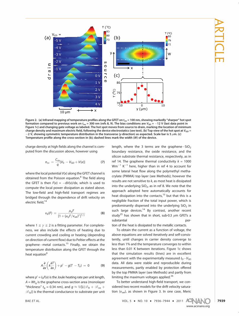
To examine this point, we measured the tempera-ture along the graphene channel with fixed VSD =�12 V
and at various gate�drain voltages, VGD, as shown in
Figure 2a. At VGD =�5 V (,V0) the drain is heavily hole-
doped, but VGS =þ7 V, so the region near the source is
lightly electron-doped (keeping in mind that V0 = 5.2 V
for this device). Thus, the CNP is located very close to
the source and so is the hot spot, as can be seen in theupper panel of Figure 2a. As we increase VGD asmarkedin the figure, VGS continues to increase according toeq 5, reaching VGS = þ16 V (.V0) in the bottom panelof Figure 2a. At this point, the source is heavilyelectron-doped and the drain is lightly hole-doped,very close to the CNP (VGD = 4 V < V0 = 5.2 V). Thus,during the entire imaging sequence shown in Figure 2atheGFET is operating in the ambipolar transport regime,but changing the gate voltage gradually alters the rela-tive electron and hole concentrations, moving the hotspot (location of CNP) from near the source to near thedrain. This experimental trace of the CNP also providesan excellent tool for checking the validity of electronicand thermal transport models under such inhomoge-neous carrier density along the channel.
To complement the thermal imaging along theGFET (x-direction), Figure 2b and c show a top viewof the hot spot at VGD = �2 V and a thermal cross-section of the GFET along the dashed line (y-direction)as indicated. We note that thewidth of the GFET here isonly slightly larger than the IR resolution (see Methods),and thus the cross-section view should be used only forqualitative inspection. By comparison, higher resolutionscanning Joule expansion microscopy (SJEM)15 has re-vealed a uniform transverse temperature profile withslightly cooler edges fromheat sinking andhigher carrierdensity due to fringing heat and electric field effects.
High-Field Electrothermal Model. Our graphene devicesimulation approach was partially described in pre-vious publications,8,14,15 and here we briefly review afew more salient features. The model is qualitativelysimilar to other approaches;11�13 however it is the onlyone (to our knowledge) to self-consistently include thethermal effects during high-field transport. The currentcontinuity equation is given by eq 6 and must besatisfied at every point along the GFET channel. The
Figure 1. (a) Schematic of GFET (top) and optical image of fabricated device (bottom). Device dimensions are L= 28.8 μm,W =5 μm, tox = 100 nm; scale bar is 10 μm. (b) Resistance vsback-gate voltage, experimental data (points) andmodelfit (lines). Thefitted contact resistance RC is also shown, a function of gate voltage (see model and text). (c) Drain current vs source�drainvoltage at various back-gate voltages; measured data (points) and simulations (lines). The two nearly overlapping families oflines (solid and dashed) are simulations with the two velocity saturation models (see text).
ARTIC
LE
BAE ET AL . VOL. 5 ’ NO. 10 ’ 7936–7944 ’ 2011
www.acsnano.org
7939
charge density at high fields along the channel is com-puted from the discussion above, however using
ncv ¼ Coxq[V0 � VGD þ V(x)] (7)
where the local potential V(x) along theGFET channel isobtained from the Poisson equation.8 The field alongthe GFET is then F(x) = �dV(x)/dx, which is used tocompute the local power dissipation as stated above.The low-field and high-field transport regimes arebridged through the dependence of drift velocity onelectric field,14
vd(F) ¼ μ0F
[1þ (μ0F=vsat)γ]1=γ
(8)
where 1 e γ e 2 is a fitting parameter. For complete-ness, we also include the effects of heating due tocurrent crowding and cooling or heating (dependingon direction of current flow) due to Peltier effects at thegraphene�metal contacts.15 Finally, we obtain thetemperature distribution along the GFET through theheat equation8
ADDx
kDTDx
� �þ p0 � g(T � T0) ¼ 0 (9)
where p0 = IDF(x) is the Joule heating rate per unit length,A =Wtg is the graphene cross-section area (monolayer“thickness” tg = 0.34 nm), and g ≈ 1/[L(R B þ R ox þR Si)] is the thermal conductance to substrate per unit
length, where the 3 terms are the graphene�SiO2
boundary resistance, the oxide resistance, and thesilicon substrate thermal resistance, respectively, as inref 14. The graphene thermal conductivity k = 1000Wm�1 K�1 here, higher than in ref 4 to account forsome lateral heat flow along the polymethyl metha-crylate (PMMA) top layer (see Methods); however theresults are not sensitive to k, as most heat is dissipatedinto the underlying SiO2, as in ref 8. We note that theapproach adopted here automatically accounts forheat dissipation into the contacts,15 but that this is anegligible fraction of the total input power, which ispredominantly dispersed into the underlying SiO2 insuch large devices.14 By contrast, another recentstudy25 has shown that in short, sub-0.3 μm GFETs asubstantial por-tion of the heat is dissipated to the metallic contacts.
To obtain the current as a function of voltage, theabove equations are solved iteratively and self-consis-tently, until changes in carrier density converge toless than 1% and the temperature converges to withinless than 0.01 K between iterations. Figure 1c showsthat the simulation results (lines) are in excellentagreement with the experimentally measured ID�VSDdata. All data were stable and reproducible duringmeasurements, partly enabled by protection offeredby the top PMMA layer (see Methods) and partly fromlimiting the maximum voltages applied.26
To better understand high-field transport, we con-sidered two recent models for the drift velocity satura-tion (vsat), as shown in Figure 3. In one case, Meric
Figure 2. (a) Infraredmapping of temperature profiles along the GFET on tox = 100 nm, showingmarkedly “sharper” hot spotformation compared to previous work on tox = 300 nm (refs 8, 9). The bias conditions are VSD = �12 V (last data point inFigure 1c) and changing gate voltage as labeled. The hot spot moves from source to drain, marking the location of minimumcharge density andmaximum electric field, following the device electrostatics (see text). (b) Top view of the hot spot at VGD =�2 V, showing symmetric temperature distribution in the transverse (y-direction) as expected. Scale bar is 5 μm. (c)Temperature profile along the cross-section in (b); dashed lines mark the width (W) of the device.
ARTIC
LE

BAE ET AL . VOL. 5 ’ NO. 10 ’ 7936–7944 ’ 2011
www.acsnano.org
7940
et al.7,27 have suggested
vsat ¼ ωOPffiffiffiffiffiffiffiffiffiffiffiffiffiffiffiffiffiπ(nþ p)
p (10)
where pωOP is the dominant optical phonon (OP)energy for carrier energy relaxation. This is an approxi-mation based on a shifted Fermi disk in the limit ofT = 0 K (see Figure 3b and supplement of ref 7) and isgenerally applicable at “large” carrier density (n þ p .n0). On the other hand, following initial work by Barreiroand co-workers,28 Dorgan et al.14 have proposed
vsat ¼ 2π
ωOPffiffiffiffiffiffiffiffiffiffiffiffiffiffiffiffiffiπ(nþ p)
pffiffiffiffiffiffiffiffiffiffiffiffiffiffiffiffiffiffiffiffiffiffiffiffiffiffiffiffiffiffiffiffiffiffi1 � ωOP
2
4π(nþ p)vF2
s1
NOP þ 1, nþ pgn�
(11)
vsat ¼ 2π
vFNOP þ 1
, nþ p < n� (12)
where n* = (ωOP/vF)2/2π, NOP = 1/[exp(pωOP/kBT)� 1] is
the phonon occupation, and kB is the Boltzmann con-stant. These expressions are based on a steady-statepopulation in which carriers contributing to current flowoccupy states up to an energy pωOP higher thancarriers moving against the net current28 (Figure 3c).Note that both models suggest vsat decreases approxi-mately as the inverse square root of the carrier density,and in both models pωOP is treated as a fitting para-meter. However, vsat in the Meric model is derived inthe limit T = 0 K and can approach infinity as the carrierdensity tends to zero. The Dorgan model includes asemiempirical temperature dependence14 and appro-aches a constant at low carrier density, vmax≈ (2/π)vF≈6.3� 107 cm/s (closer to∼6� 107 cm/s at 70 �C whenthe temperature dependence is taken into account, asin eq 12 and Figure 3a).
Consistent with the previous studies7,14,27 wechoose pωOP = 59 meV (γ = 1.3 in eq 8) and 81 meV(γ= 1.5) for theMeric andDorganmodels, respectively.These are consistent with the SiO2 surface phononenergy and with a combination between the SiO2
phonon and graphene optical phonon energy, respec-tively. The phonon energy fitting parameters werechosen so as to yield virtually indistinguishable char-acteristics in Figure 1c. We plot vsat from the two modelsas a function of total carrier density (nþ p) in Figure 3a,showing the expected behavior as described above.With our present parameters, the Dorgan model reachesa constant below charge densities n þ p < n* = 2.4 �1011 cm�2. However, we note that the minimumcharge density achieved during all simulations in thiswork was ∼4 � 1011 cm�2 due to puddle charge andthermally excited carriers. In addition, the maximumlongitudinal fields26were∼0.9 V/μm(see Figure 4), andthus complete velocity saturationwasnever fully reached(see, e.g., Figure 3 of ref 14). This explains that relativelygood agreement can be attained between eithermodel and our data in Figure 1c, within the presentconditions. (Future work on shorter devices at higherelectric fields26 will be needed to elucidate the role ofsaturation velocity at low carrier density.)
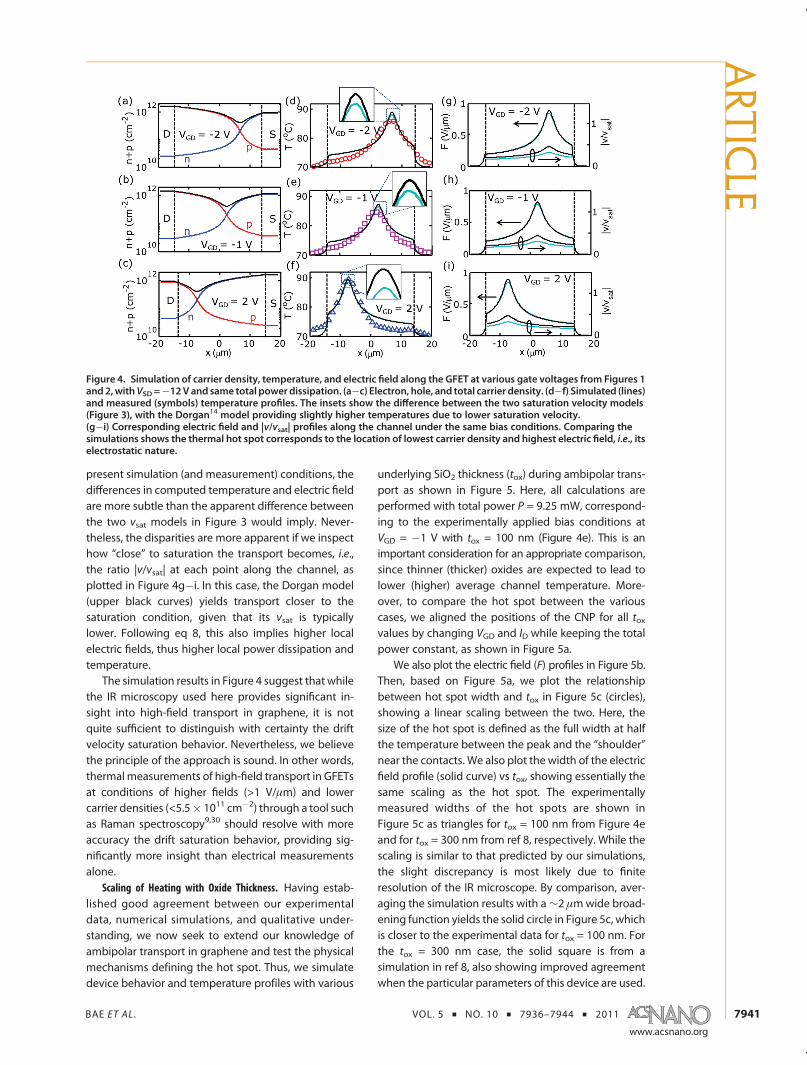
Comparison of Simulation with Data. With the para-meters discussed above, Figure 4 shows carrier den-sities and temperature profiles at the last drain biaspoint (VSD = �12 V) for three representative gatevoltages, VGD = �2, �1, and 2 V. Once again, excellentagreement is found between simulation results ob-tained with the two different vsat models (solid curves)and the experimental temperature profiles (symbols).29
The position of the CNP for each VGD can be visualizedby comparing Figure 4a�c with Figure 4d�f as thecrossing point of electron and hole carrier densityprofiles and that of the hot spot. We also plot thecorresponding electric fields in Figure 4g�i, where theposition of the maximum field matches that of the hotspot. The CNP clearly moves from source to drain whenthe gate voltage changes, as visualized in Figure 2 andpreviously explained in qualitative terms. We note thatthe profile of the hot spot with 100 nm underlyingoxide thickness (Figures 2 and 4 here) is much betterdefined and “sharper” than what was previously ob-served on 300 nm oxide.8,9
Comparing the simulations obtained with the twovsat models, we note that the carrier density profiles arenearly identical in Figure 4a�c. However, the lower vsat(at a given carrier density) of theDorganmodel14 yieldsslightly higher electric fields and higher hot spottemperatures, as shown in Figure 4d�i (also see theinsets). The temperature difference here is up to∼1 �Cbetween the two models, or ∼5% of the total tem-perature change, although the applied power is thesame between the separate simulations. We note thatsince velocity saturation is never fully reached in the
Figure 3. (a) High-field saturation velocity models vs carrierdensity.7,14,28 At low density, here <2.4 � 1011 cm�2, theDorgan14 model reaches a constant value (∼2vF/π ≈ 6.3 �107 cm/s, slightly lower here at∼70 �C, see eq 12), whereastheMeric7model can diverge. However, due to temperatureeffects andpuddle charge, the carrier density in our device isalways >4 � 1011 cm�2 during operation, as marked by anarrow. Thus, in the device simulated here either model canbe applied, as in Figures 1 and 4. (b, c) Schematic assump-tions of carrier distribution at high field used to derive theclosed-form vsat expressions in the (b) Meric7 and (c) Dor-gan14 models.
ARTIC
LE
BAE ET AL . VOL. 5 ’ NO. 10 ’ 7936–7944 ’ 2011
www.acsnano.org
7941
present simulation (and measurement) conditions, thedifferences in computed temperature and electric fieldare more subtle than the apparent difference betweenthe two vsat models in Figure 3 would imply. Never-theless, the disparities are more apparent if we inspecthow “close” to saturation the transport becomes, i.e.,the ratio |v/vsat| at each point along the channel, asplotted in Figure 4g�i. In this case, the Dorgan model(upper black curves) yields transport closer to thesaturation condition, given that its vsat is typicallylower. Following eq 8, this also implies higher localelectric fields, thus higher local power dissipation andtemperature.
The simulation results in Figure 4 suggest that whilethe IR microscopy used here provides significant in-sight into high-field transport in graphene, it is notquite sufficient to distinguish with certainty the driftvelocity saturation behavior. Nevertheless, we believethe principle of the approach is sound. In other words,thermal measurements of high-field transport in GFETsat conditions of higher fields (>1 V/μm) and lowercarrier densities (<5.5� 1011 cm�2) through a tool suchas Raman spectroscopy9,30 should resolve with moreaccuracy the drift saturation behavior, providing sig-nificantly more insight than electrical measurementsalone.
Scaling of Heating with Oxide Thickness. Having estab-lished good agreement between our experimentaldata, numerical simulations, and qualitative under-standing, we now seek to extend our knowledge ofambipolar transport in graphene and test the physicalmechanisms defining the hot spot. Thus, we simulatedevice behavior and temperature profiles with various
underlying SiO2 thickness (tox) during ambipolar trans-port as shown in Figure 5. Here, all calculations areperformed with total power P = 9.25 mW, correspond-ing to the experimentally applied bias conditions atVGD = �1 V with tox = 100 nm (Figure 4e). This is animportant consideration for an appropriate comparison,since thinner (thicker) oxides are expected to lead tolower (higher) average channel temperature. More-over, to compare the hot spot between the variouscases, we aligned the positions of the CNP for all toxvalues by changing VGD and ID while keeping the totalpower constant, as shown in Figure 5a.
We also plot the electric field (F) profiles in Figure 5b.Then, based on Figure 5a, we plot the relationshipbetween hot spot width and tox in Figure 5c (circles),showing a linear scaling between the two. Here, thesize of the hot spot is defined as the full width at halfthe temperature between the peak and the “shoulder”near the contacts. We also plot the width of the electricfield profile (solid curve) vs tox, showing essentially thesame scaling as the hot spot. The experimentallymeasured widths of the hot spots are shown inFigure 5c as triangles for tox = 100 nm from Figure 4eand for tox = 300 nm from ref 8, respectively. While thescaling is similar to that predicted by our simulations,the slight discrepancy is most likely due to finiteresolution of the IR microscope. By comparison, aver-aging the simulation results with a∼2 μmwide broad-ening function yields the solid circle in Figure 5c, whichis closer to the experimental data for tox = 100 nm. Forthe tox = 300 nm case, the solid square is from asimulation in ref 8, also showing improved agreementwhen the particular parameters of this device are used.
Figure 4. Simulation of carrier density, temperature, and electric field along the GFET at various gate voltages from Figures 1and2,withVSD =�12V and same total powerdissipation. (a�c) Electron, hole, and total carrier density. (d�f) Simulated (lines)and measured (symbols) temperature profiles. The insets show the difference between the two saturation velocity models(Figure 3), with the Dorgan14 model providing slightly higher temperatures due to lower saturation velocity.(g�i) Corresponding electric field and |v/vsat| profiles along the channel under the same bias conditions. Comparing thesimulations shows the thermal hot spot corresponds to the location of lowest carrier density and highest electric field, i.e., itselectrostatic nature.
ARTIC
LE

BAE ET AL . VOL. 5 ’ NO. 10 ’ 7936–7944 ’ 2011
www.acsnano.org
7942
As the oxide thickness is scaled down from tox = 300to 20 nm, we find that both the average channel tem-perature (Figure 5d) and the width of the hot spotdecrease (Figure 5c); that is, the hot spot becomes“sharper”. The former occurs because the thermalresistance of the SiO2 is lowered, and the latter is dueto increasing capacitive coupling between the back-gate and the charge carriers in the channel. We notethat the average channel temperature in Figure 5ddoes not reach the base temperature (here, T0 = 70 �C)even in the limit of vanishing tox due to the remainingthermal resistance of the silicon substrate and of thegraphene�SiO2 boundary. To understand this, we notethat the average thermal resistance of the devicecan be estimated as14 R th ≈R ox þR B þR Si, whereR ox≈ tox/(koxLW) is the thermal resistance of the SiO2,which scales with tox, but the second and third termsare the graphene�SiO2 boundary thermal resistance14,31
and the spreading thermal resistance14,24 of the sili-con substrate, which are independent of the oxidethickness.
Interestingly, Figure 5d indicates that the peak
temperature of the hot spot (Tmax) begins to increase
when tox is scaled below ∼90 nm, despite a loweraverage temperature in the channel. This trend occursbecause the Joule heating effect induced by the highelectric field at the CNP overcomes the cooling effect ofthe lowered oxide thickness at tox ≈ 90 nm. To gainmore insight into this observation, we return to the
temperature and electric field profiles along the gra-phene channel in Figure 5a and 5b. We note that thetemperature qualitatively follows the electric fieldprofile, and the source of the hot spot is clearlyelectrostatic in nature. In addition, this finding sug-gests that one should consider the formation of highlylocalized hot spots in future devices that would havethinner underlying oxide layers. While a thinner toxdoes lead to a lower average temperature, the peak
temperature is actually increased due to electrostaticeffects. This effect is expected to be the same in top-gated as in bottom-gated graphene devices, becausethe electrostatic effects are controlled by the gate,whereas heat flow is limited by the underlying oxide.The local temperature increase and highly localizedelectric field at the hot spot could lead to long-termoxide reliability issues,16 which must be accounted for.
CONCLUSION
In summary, we have examined the physical me-chanisms behind high-field hot spot formation ingraphene transistors on SiO2 and found them tobe electrostatic in nature. Using self-consistentelectrothermal simulations and infrared thermalimaging, we established that the maximum tem-perature of a graphene device in high-field opera-tion is sensitive to the peak electric field and carriersaturation velocity. We have also confirmed thatthe average temperature of a functioning GFET
Figure 5. Scaling of GFET hot spot and electric field as a function of underlying SiO2 thickness. (a) Calculated temperatureprofiles along devicewith power input 9.25mW, corresponding to Figure 4e. (b) Calculated electric field profiles under thesame conditions. (c) Scaling of hot spot width (symbols) and electric field width (lines) with tox. Triangles are experimentaldata for GFETs on tox = 100 nm (this work) and 300 nm (ref 8). Circles are calculated widths of the hot spot (see text).(d) Scaling of maximum (Tmax) and average GFET temperature (Tavg) with tox from (a). Dashed lines are analytic fits. Theaverage temperature Tavg does not approach T0 (=70 �C here) in the limit tox f 0 due to the combined effect of thegraphene�SiO2 and silicon substrate thermal resistance (R BþR Si), which are independent of tox (see text after eq 9 andref 14).
ARTIC
LE
BAE ET AL . VOL. 5 ’ NO. 10 ’ 7936–7944 ’ 2011
www.acsnano.org
7943
scales proportionally with the thickness of the sup-porting SiO2, as expected. However, the maximumtemperature of such GFETs can be minimized for agiven insulator thickness (here∼90 nm for SiO2) due to
competing electrostatic and heat sinking effects. Theseresults suggest a route for the optimization of gra-phene substrates for proper heat dissipation and high-light existing trade-offs for practical device reliability.
METHODSWe prepared exfoliated monolayer graphene devices on
tox = 100 nm thermally grown SiO2 on highly doped Si sub-strates, which also serve as the back-gate. The graphene layernumber was confirmed by optical microscopy and Ramanspectroscopy.32,33 Source and drain contacts are patterned byelectron-beam (e-beam) lithography and deposited with Cr(0.5 nm)/Pd (40 nm) by thermal evaporation at 5 � 10�7 Torrbase pressure. After lift-off, a rectangular graphene shape(length L = 28.8 μm, width W = 5 μm) is defined by e-beamlithography and oxygen plasma etching, as shown in Figure 1.Finally, a ∼70 nm PMMA layer is spun over the substrate, toprotect the graphene from spurious doping or ambient moist-ure during the measurements.8 Thermal imaging is performedusing a QFI InfraScope II IR microscope with 15� objective,spatial resolution of 2.8 μm, pixel size of 1.6 μm, and tempera-ture resolution of ∼0.1 �C after calibration.34 All thermal IRmeasurements were performed in air at a base temperature T0 =70 �C, as needed for optimal IR detector sensitivity.8,34
Acknowledgment. We thank Z.-Y. Ong for several usefuldiscussionsandF. Lian forproviding thedevice schematic inFigure1.This work was supported in part by the Office of Naval Research(ONR), the National Science Foundation (NSF) CAREER award, andthe Air Force Young Investigator Program (YIP). V.E.D. acknowledgessupport through a NSF Graduate Research Fellowship.
REFERENCES AND NOTES1. Geim, A. K.; Kim, P. CarbonWonderland. Sci. Am. 2008, 298,
90–97.2. Bolotin, K. I.; Sikes, K. J.; Hone, J.; Stormer, H. L.; Kim, P.
Temperature-Dependent Transport in Suspended Gra-phene. Phys. Rev. Lett. 2008, 101, 096802.
3. Balandin, A. A. Thermal Properties of Graphene andNanostructured Carbon Materials. Nat. Mater. 2011, 10,569–581.
4. Seol, J. H.; Jo, I.; Moore, A. L.; Lindsay, L.; Aitken, Z. H.; Pettes,M. T.; Li, X.; Yao, Z.; Huang, R.; Broido, D.; Mingo, N.; Ruoff,R. S.; Shi, L. Two-Dimensional Phonon Transport in Sup-ported Graphene. Science 2010, 328, 213–216.
5. Lin, Y. M.; Dimitrakopoulos, C.; Jenkins, K. A.; Farmer, D. B.;Chiu, H. Y.; Grill, A.; Avouris, P. 100-GHz Transistors fromWafer-Scale Epitaxial Graphene. Science 2010, 327, 662.
6. Mueller, T.; Xia, F.; Avouris, P. Graphene Photodetectors forHigh-Speed Optical Communications. Nat. Photon 2010,4, 297–301.
7. Meric, I.; Han,M. Y.; Young, A. F.; Ozyilmaz, B.; Kim, P.; Shepard,K. L. Current Saturation in Zero-Bandgap, Top-GatedGraphene Field-Effect Transistors. Nat. Nanotechnol. 2008,3, 654–659.
8. Bae, M.-H.; Ong, Z.-Y.; Estrada, D.; Pop, E. Imaging, Simula-tion, and Electrostatic Control of Power Dissipation inGraphene Devices. Nano Lett. 2010, 10, 4787–4793.
9. Freitag, M.; Chiu, H.-Y.; Steiner, M.; Perebeinos, V.; Avouris,P. Thermal Infrared Emission from Biased Graphene. Nat.Nanotechnol. 2010, 5, 497–501.
10. Jo, I.; Hsu, I. K.; Lee, Y. J.; Sadeghi, M. M.; Kim, S.; Cronin, S.;Tutuc, E.; Banerjee, S. K.; Yao, Z.; Shi, L. Low-FrequencyAcoustic Phonon Temperature Distribution in ElectricallyBiased Graphene. Nano Lett. 2011, 11, 85–90.
11. Thiele, S. A.; Schaefer, J. A.; Schwierz, F. Modeling ofGraphene Metal-Oxide-Semiconductor Field-Effect Tran-
sistors with Gapless Large-Area Graphene Channels. J. Appl.Phys. 2010, 107, 094505–8.
12. Champlain, J. G. A First Principles Theoretical Examinationof Graphene-Based Field Effect Transistors. J. Appl. Phys.2011, 109, 084515–19.
13. Wang, H.; Hsu, A.; Kong, J.; Antoniadis, D. A.; Palacios, T.Compact Virtual-Source Current-Voltage Model for Top-andBack-GatedGrapheneField-Effect Transistors. IEEE Trans.Electron Devices 2011, 58, 1523–1533.
14. Dorgan, V. E.; Bae, M.-H.; Pop, E. Mobility and SaturationVelocity in Graphene on SiO2. Appl. Phys. Lett. 2010, 97,082112.
15. Grosse, K. L.; Bae, M.-H.; Lian, F.; Pop, E.; King, W. P.Nanoscale Joule Heating, Peltier Cooling and CurrentCrowding at Graphene-Metal Contacts. Nat. Nanotechnol.2011, 6, 287.
16. Schroder, D. K.; Babcock, J. A. Negative Bias TemperatureInstability: Road to Cross in Deep Submicron Silicon Semi-conductor Manufacturing. J. Appl. Phys. 2003, 94, 1–18.
17. Zhu, W. J.; Perebeinos, V.; Freitag, M.; Avouris, P. CarrierScattering, Mobilities, and Electrostatic Potential in Mono-layer, Bilayer, and Trilayer Graphene. Phys. Rev. B 2009, 80,235402.
18. Martin, J.; Akerman, N.; Ulbricht, G.; Lohmann, T.; Smet,J. H.; von Klitzing, K.; Yacoby, A. Observation of Electron-Hole Puddles in Graphene Using a Scanning Single-Elec-tron Transistor. Nat. Phys. 2008, 4, 144–148.
19. Fang, T.; Konar, A.; Xing, H.; Jena, D. Carrier Statistics andQuantum Capacitance of Graphene Sheets and Ribbons.Appl. Phys. Lett. 2007, 91, 092109–3.
20. Nagashio, K.; Nishimura, T.; Kita, K.; Toriumi, A. ContactResistivity and Current Flow Path at Metal/GrapheneContact. Appl. Phys. Lett. 2010, 97, 143514.
21. Xia, F.; Perebeinos, V.; Lin, Y.-M.; Wu, Y.; Avouris, P. TheOrigins and Limits ofMetal-Graphene Junction Resistance.Nat. Nanotechnol. 2011, 6, 179–184.
22. Fang, T.; Konar,A.; Xing, H.; Jena, D. High Field Transport in 2DGraphene. (cond/mat pre-print) 2010, arXiv:1008.1161v1.
23. Li, X.; Barry, E. A.; Zavada, J. M.; Nardelli, M. B.; Kim, K. W.Surface Polar Phonon Dominated Electron Transport inGraphene. Appl. Phys. Lett. 2010, 97, 232105.
24. Pop, E. Energy Dissipation and Transport in NanoscaleDevices. Nano Res. 2010, 3, 147–169.
25. Liao, A. D.; Wu, J. Z.; Wang, X.; Tahy, K.; Jena, D.; Dai, H.; Pop,E. Thermally Limited Current Carrying Ability of GrapheneNanoribbons. Phys. Rev. Lett. 2011, 106, 256801.
26. In this work, as in ref 8, we limited the maximum lateralfields to F < ∼0.9 V/μm and the maximum tempera-ture rise to ΔT < ∼100 K (Tmax ∼ 170 �C) in order toobtain reproducible device behavior between subse-quent IR and electrical measurements.
27. Meric, I.; Dean, C. R.; Young, A. F.; Baklitskaya, N.; Tremblay,N. J.; Nuckolls, C.; Kim, P.; Shepard, K. L. Channel LengthScaling in Graphene Field-Effect Transistors Studied withPulsed Current�Voltage Measurements. Nano Lett. 2011,11, 1093–1097.
28. Barreiro, A.; Lazzeri, M.; Moser, J.; Mauri, F.; Bachtold, A.Transport Properties of Graphene in the High-CurrentLimit. Phys. Rev. Lett. 2009, 103, 076601.
29. A slight discrepancy between simulated and measuredtemperature is sometimes found near the metal contacts,as previously noted in ref 8. The discrepancy is partlyattributed to inhomogeneous charge storage in SiO2 afterpersistent high-field device operation and partly to the IR
ARTIC
LE

BAE ET AL . VOL. 5 ’ NO. 10 ’ 7936–7944 ’ 2011
www.acsnano.org
7944
imaging approach itself with the signal being a more com-plex convolution from several surfaces (including the metal)near the contacts. More careful, ultra-high-resolution AFM-based thermal imaging at lower bias (ref 15) found near-perfect agreement between our simulations and the tem-perature profile near the contacts.
30. Tsai, C.-L.; Liao, A.; Pop, E.; Shim, M. Electrical PowerDissipation in Semiconducting Carbon Nanotubes onSingle Crystal Quartz and Amorphous SiO2. Appl. Phys.Lett. 2011, 99, 053120.
31. Koh, Y. K.; Bae, M.-H.; Cahill, D. G.; Pop, E. Heat Conductionacross Monolayer and Few-Layer Graphenes. Nano Lett.2010, 10, 4363–4368.
32. Wang, Z.; Chun, I. S.; Li, X.; Ong, Z.-Y.; Pop, E.; Millet, L.;Gillette, M.; Popescu, G. Topography and Refractometry ofNanostructures Using Spatial Light Interference Micro-scopy. Opt. Lett. 2010, 35, 208–210.
33. Koh, Y. K.; Bae, M.-H.; Cahill, D. G.; Pop, E. Reliably CountingAtomic Planes of Few-Layer Graphene (n > 4). ACS Nano2011, 5, 269–274.
34. QFI Corp., Infrascope II User Manual. www.quantumfocus.com, 2005.
ARTIC
LE


![1374 bae[1]](https://img.pdfslide.us/doc/110x75/5590c45a1a28ab9d718b45d3/1374-bae1.jpg)


![1047 bae[1]](https://img.pdfslide.us/doc/110x75/5562973cd8b42abb398b4d64/1047-bae1.jpg)