Embed Size (px)
Citation preview

AG-100, AG-200, AG-300 & AG-400
Installation & Operation Manual
Electronic Lime Scale Control System115/230 VAC (Auto Selected)
AG-300 for pipe sizes up to 3" (non-ferrous)
AG-400 for pipe sizes up to 4" (non-ferrous)
AG-100 for pipe sizes up to 1 ½" (non-ferrous)
AG-200 for pipe sizes up to 2" (non-ferrous)
7/14
Electronic Lime Scale Control Systemfor Agriculture Applications

Page 2
AG Commercial Units - 5 YEAR LIMITED WARRANTY
Clearwater Enviro Technologies, Inc. • 8767 115th Ave. N. • Largo, FL 33773
®All ScaleBlaster AG commercial electronic descaler products carry a full five (5) year warranty to be free from defects in material and workmanship under normal use from the date of purchase. In the event of malfunction or failure of this product, the purchaser should contact their dealer for service. If distributor is unavailable, contact Clearwater Enviro Tech direct at 800-756-7946 or 727-562-5186 or by fax 727-562-5187 or going to their website at clearwater-enviro.com to obtain an RMA (return merchandise number). Properly package the entire unit and ship it prepaid with a note containing the RMA number, your name, address, phone number (or best way to contact you) along with a brief description of the difficulty you are experiencing with the unit to:
Please be sure to also write the RMA number on the outside of the shipping box.
If the malfunction or failure is a result of defects covered by this warranty, Clearwater Enviro Tech will repair the product or replace it and return it to the purchaser. After a period of five years, a small labor and parts charge will occur.
This warranty is limited to the original retail purchaser and is not transferable. This warranty does not cover damage due to accidents, abuse, tampering, misuse, fire, lightning damage, power surge, flooding or any catastrophic acts of God.
This warranty does not extend to any other electrical or water appliance or device.
In no event shall the manufacturer be liable for damages from improper user installation, nor shall they be liable for already damaged pipe and any consequential damages incurred, whether direct or indirect.
This warranty is limited to repair or replacement and does not include consequential damage or installation expenses and is in lieu of all other warranties express or implied. This warranty gives you specific rights and you may also have other rights, which vary from state to state.
Electronic Lime Scale Control Systemfor Agriculture Applications
Section Description PageProduct Warranty Information................................................................. 2
®A) Identifying the Scaleblaster AG Components...................................... 3B) Tools and Materials Required.................................................................. 3C) Site Survey............................................................................................... 4, 5D) Mounting the Power Box......................................................................... 6E) Installing the Signal Cable....................................................................... 6, 7F) Powering up the Control Box / Computer............................................... 8G) LCD Indicator Screen.............................................................................. 8
Page 3
Table of Contents
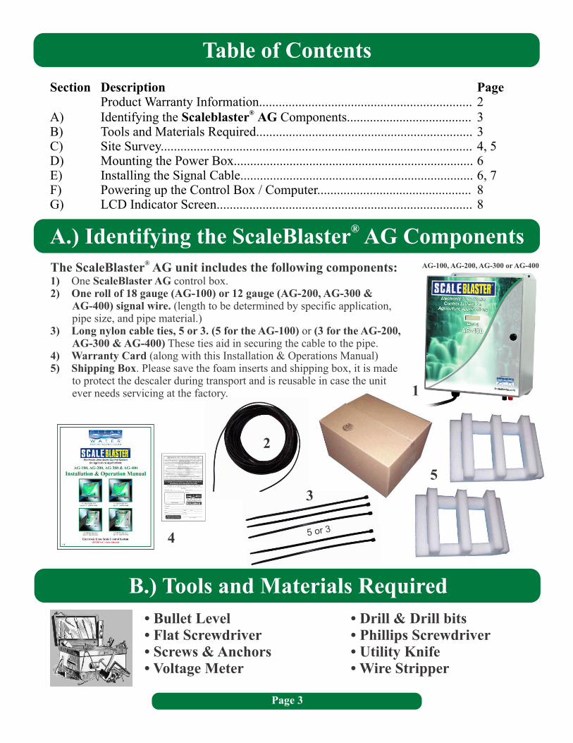
A.) Identifying the ScaleBlaster® AG Components®The ScaleBlaster AG unit includes the following components:
1) One ScaleBlaster AG control box.2) One roll of 18 gauge (AG-100) or 12 gauge (AG-200, AG-300 &
AG-400) signal wire. (length to be determined by specific application, pipe size, and pipe material.)
3) Long nylon cable ties, 5 or 3. (5 for the AG-100) or (3 for the AG-300 & AG-400) These ties aid in securing the cable to the pipe.
4) Warranty Card (along with this Installation & Operations Manual)5) Shipping Box. Please save the foam inserts and shipping box, it is made
to protect the descaler during transport and is reusable in case the unit ever needs servicing at the factory.
AG-200,
1
2
3
4
5
• Bullet Level • Drill & Drill bits• Flat Screwdriver • Phillips Screwdriver• Screws & Anchors • Utility Knife• Voltage Meter • Wire Stripper
AG-100, AG-200, AG-300 or AG-400
B.) Tools and Materials Required
5 or 3
Page 4
C.) Site Survey
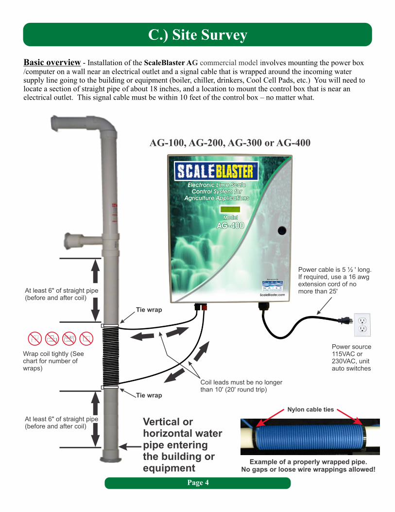
Basic overview - Installation of the ScaleBlaster A nvolves mounting the power box /computer on a wall near an electrical outlet and a signal cable that is wrapped around the incoming water supply line going to the building or equipment (boiler, chiller, drinkers, Cool Cell Pads, etc.) You will need to locate a section of straight pipe of about 18 inches, and a location to mount the control box that is near an electrical outlet. This signal cable must be within 10 feet of the control box – no matter what.
G commercial model i
At least 6" of straight pipe (before and after coil)
Wrap coil tightly (See chart for number of wraps)
At least 6" of straight pipe (before and after coil)
Tie wrap
Tie wrap
Power cable is 5 ½ ' long.If required, use a 16 awg extension cord of no more than 25'
Power source 115VAC or 230VAC, unit auto switches
Coil leads must be no longer than 10' (20' round trip)
Vertical or horizontal water pipe entering the building or equipment
AG-100, AG-200, AG-300 or AG-400
Example of a properly wrapped pipe.No gaps or loose wire wrappings allowed!
Nylon cable ties
C.) Site Survey (Continued)
Type of Pipe - This ScaleBlaster AG commercial model will work on PVC, CPVC, PEX or copper pipe up to:one and a half (1 ½) inch in diameter for the AG-100,two (2) inches in diameter for the AG-200, three (3) inches in diameter for the AG-300,four (4) inches in diameter for the AG-400.
If the pipe is galvanized or magnetic pipe, the unit will not penetrate it and will not work. By magnetic pipe, we mean that if you put a magnet on the pipe and it sticks, it is magnetic. The pipe may be stainless steel, or steel and appear to be magnetic, but not magnetic. So please test with a magnet to make sure if there is any doubt. THIS IS EXTREMELY IMPORTANT.
If you only have galvanized or steel pipe to install the unit on, there are two options. You can replace about a foot or so of the pipe with either copper or
Location of the install - applications, it is impossible to list them all. However, the most desirable place to install the equipment is at the main water supply line going to the building or in front of the equipment. If the system has recycled water, you can also place the equipment on that line. It is best to consult your dealer or Clearwater Enviro Tech if you have any questions. Your main goal is to treat 100% of the water as often as possible. The unit should stay on 24 hours a day. The unit can be installed to cycle with electrical timers and pumps. The unit must be on when water is flowing.
The unit may be installed indoors or outdoors, as the unit is in a weatherproof, UL, CUL and CE listed enclosure. If outdoors, make sure the install area is out of direct sunlight. In extremely hot or cold areas of the world, it may be best to enclose our power box / computer in another box to protect the LCD window and other inside components.
The power unit should be mounted on a wall or solid surface within 5 ½ feet from an electrical outlet, and within ten (10) feet from the pipe in which the signal cable will be wrapped. If the power unit has to be more than 10 feet of where the signal cable will be wrapped, you should contact your dealer or call Clearwater Enviro Tech for assistance.
The ScaleBlasterAG commercial unit has a 115 VAC power plug on the end of the cord. If the electrical outlet is more than 5 ½ feet away from where the power box / computer is mounted, you can add an UL listed and commercial grade extension cord of up to 25 feet. This is not recommended, but can be done if necessary. If the outlet is 230 VAC, you can simply remove the power plug and wire it to the power source. The unit will automatically adjust to 115 or 230 VAC with no adjustments required to the power box / computer.
Once the main water line (or line in front of the equipment) is located, identify a , and at least one foot away from any major electrical interference (an electric motor, for example). This
straight section must be away from elbows, couplings, tees and valves. Any agitation in the water will make it difficult to properly hit the water with the ScaleBlaster signal. If you locate a section of straight pipe, make sure it is away from the elbows, couplings, etc. as much as possible – but if you have no other options and there are elbows or couplings close by, go ahead and install the equipment.
pvc. If this is not possible, then a much larger ScaleBlaster model will be required to work on this application. Consult your distributor or Clearwater Enviro Tech for more details.
The exact location of the install depends on the application. Because ScaleBlaster has multiple
SECTION OF STRAIGHT PIPE THAT IS AT LEAST 18 INCHES LONG
It is better to add an extension cord to the power cable than it is to try and increase the coil leads.
Page 5
D.) Mounting the Power Box
E.) Installing the Signal Cable
Page 6
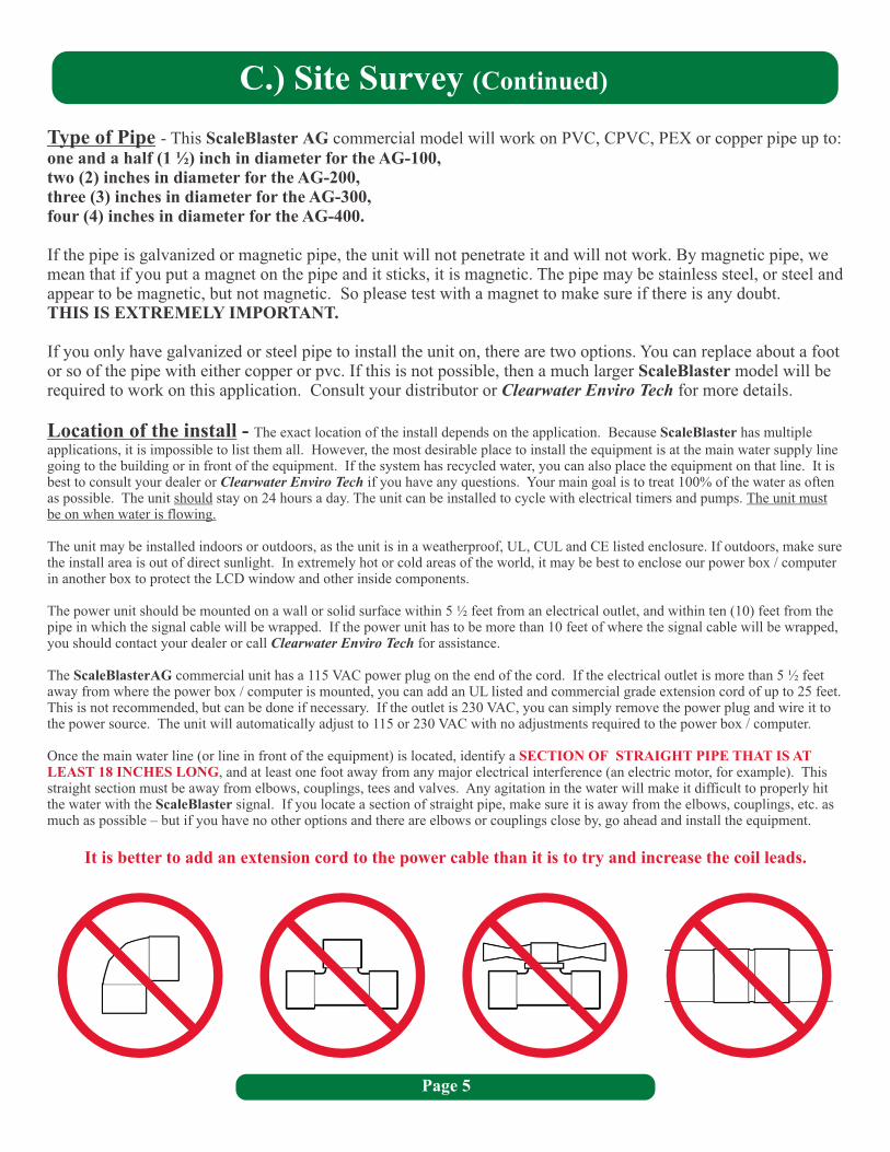
Mount the power box / computer to the wall after drilling the four holes in the determined location. Use the appropriate screws and anchors (if needed) depending on the surface (wood, stucco, etc.). This should be within 5 ½ feet of a power source and 10 feet of the location for the signal cable. If this is not possible, you may add an extension cord to the 115 VAC plug at the end of the power cord.
The unit can be installed indoors or outdoors as long as it is out of direct sunlight. The unit will work on either 115 VAC or 230 VAC with no adjustments. You can either plug the unit in a 115 VAC power outlet, or wire it directly into a 230 VAC source by removing the power plug. We strongly recommended a licensed electrician if wiring to 230 VAC.
AG-300
12.75" H8.00" W
AG-400
14.75" H10.00" W
Top and / or bottom of the power unit showing the mounting bracket (AG 200, 300 and 400). Close up of mounting hole
®1/4" Tapcon
1/4" Zinc Lag with Washer
This model is designed specifically ll not work on galvanized or magnetic pipe. You may need to replace a small section of pipe where the signal cable is to be installed if it is a ferrous based pipe. You can replace it with copper or pvc pipe. There is no need to replace the galvanized pipe downstream, as the ScaleBlaster will descale the pipes from that point forward (from the location of where the signal cable is wrapped).
This unit is equipped with a roll of 18 or 12 awg signal cable. The maximum pipe size the unit will work on is indicated in the chart on the next page.
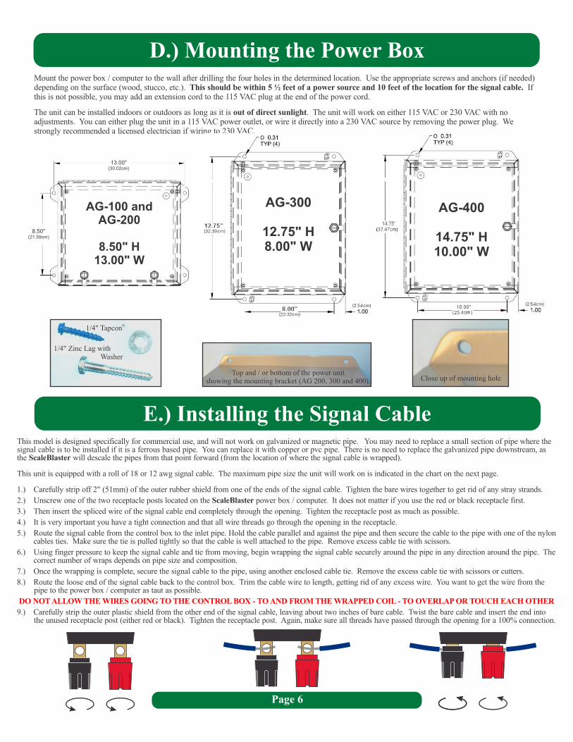
1.) Carefully strip off 2" (51mm) of the outer rubber shield from one of the ends of the signal cable. Tighten the bare wires together to get rid of any stray strands.
2.) Unscrew one of the two receptacle posts located on the ScaleBlaster power box / computer. It does not matter if you use the red or black receptacle first.
3.) Then insert the spliced wire of the signal cable end completely through the opening. Tighten the receptacle post as much as possible.
4.) It is very important you have a tight connection and that all wire threads go through the opening in the receptacle.
5.) Route the signal cable from the control box to the inlet pipe. Hold the cable parallel and against the pipe and then secure the cable to the pipe with one of the nylon cables ties. Make sure the tie is pulled tightly so that the cable is well attached to the pipe. Remove excess cable tie with scissors.
6.) Using finger pressure to keep the signal cable and tie from moving, begin wrapping the signal cable securely around the pipe in any direction around the pipe. The correct number of wraps depends on pipe size and composition.
7.) Once the wrapping is complete, secure the signal cable to the pipe, using another enclosed cable tie. Remove the excess cable tie with scissors or cutters.
8.) Route the loose end of the signal cable back to the control box. Trim the cable wire to length, getting rid of any excess wire. You want to get the wire from the pipe to the power box / computer as taut as possible.
9.) Carefully strip the outer plastic shield from the other end of the signal cable, leaving about two inches of bare cable. Twist the bare cable and insert the end into the unused receptacle post (either red or black). Tighten the receptacle post. Again, make sure all threads have passed through the opening for a 100% connection.
for commercial use, and wi
DO NOT ALLOW THE WIRES GOING TO THE CONTROL BOX - TO AND FROM THE WRAPPED COIL - TO OVERLAP OR TOUCH EACH OTHER
AG-100 andAG-200
8.50" H13.00" W
13.00(30.02cm)
"
8.50(21.59cm)
"
Page 7
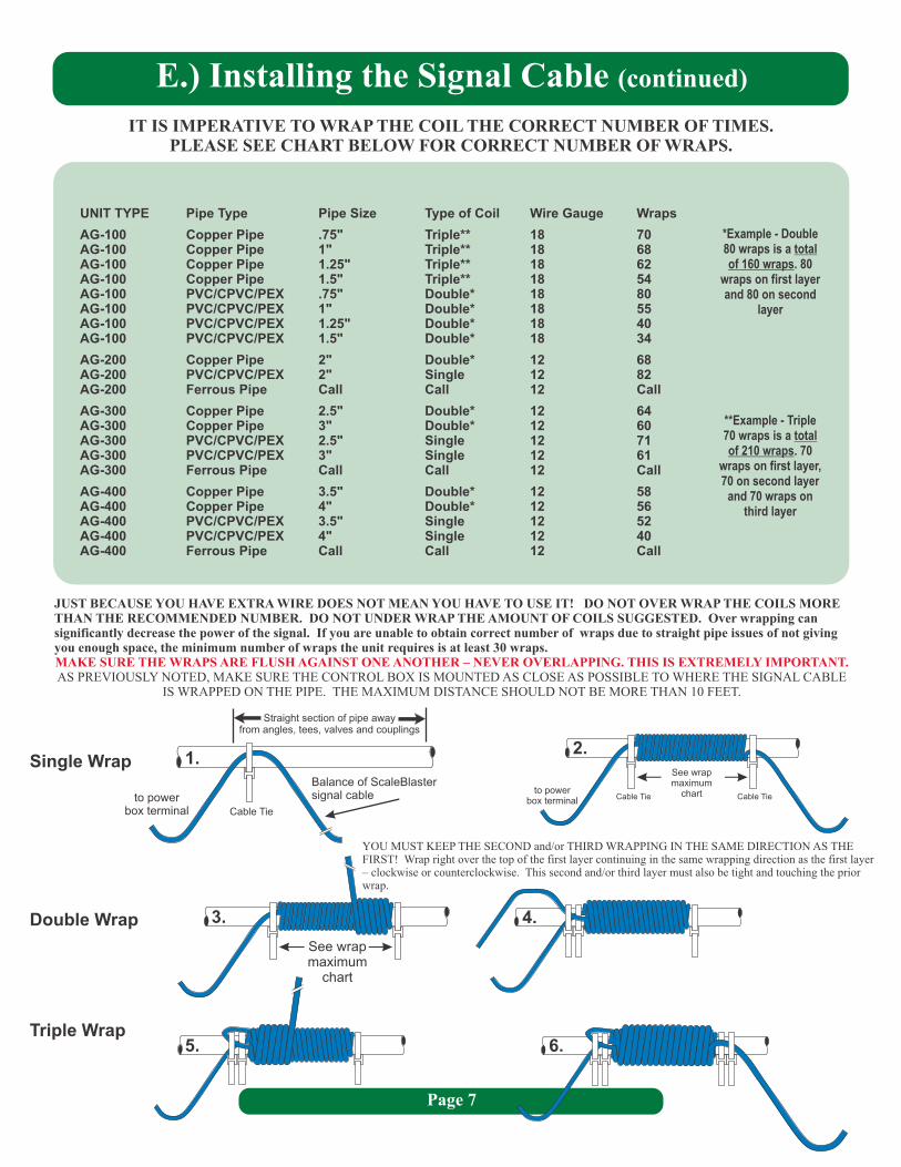
UNIT TYPE Pipe Type Pipe Size
AG-100 Copper Pipe .75" Triple** 18 70AG-100 Copper Pipe 1" Triple** 18 68AG-100 Copper Pipe 1.25" Triple** 18 62AG-100 Copper Pipe 1.5" Triple** 18 54AG-100 PVC/CPVC/PEX .75" Double* 18 80AG-100 PVC/CPVC/PEX 1" Double* 18 55AG-100 PVC/CPVC/PEX 1.25" Double* 18 40AG-100 PVC/CPVC/PEX 1.5" Double* 18 34
AG-200 Copper Pipe 2" Double* 12 68AG-200 PVC/CPVC/PEX 2" Single 12 82AG-200 Ferrous Pipe Call Call 12 Call
AG-300 Copper Pipe 2.5" Double* 12 64AG-300 Copper Pipe 3" Double* 12 60AG-300 PVC/CPVC/PEX 2.5" Single 12 71AG-300 PVC/CPVC/PEX 3" Single 12 61AG-300 Ferrous Pipe Call Call 12 Call
AG-400 Copper Pipe 3.5" Double* 12 58AG-400 Copper Pipe 4" Double* 12 56AG-400 PVC/CPVC/PEX 3.5" Single 12 52AG-400 PVC/CPVC/PEX 4" Single 12 40AG-400 Ferrous Pipe Call Call 12 Call
Type of Coil Wire Gauge Wraps
E.) Installing the Signal Cable (continued)
IT IS IMPERATIVE TO WRAP THE COIL THE CORRECT NUMBER OF TIMES. PLEASE SEE CHART BELOW FOR CORRECT NUMBER OF WRAPS.
JUST BECAUSE YOU HAVE EXTRA WIRE DOES NOT MEAN YOU HAVE TO USE IT! DO NOT OVER WRAP THE COILS MORE THAN THE RECOMMENDED NUMBER. DO NOT UNDER WRAP THE AMOUNT OF COILS SUGGESTED. Over wrapping can significantly decrease the power of the signal. If you are unable to obtain correct number of wraps due to straight pipe issues of not giving you enough space, the minimum number of wraps the unit requires is at least 30 wraps.
AS PREVIOUSLY NOTED, MAKE SURE THE CONTROL BOX IS MOUNTED AS CLOSE AS POSSIBLE TO WHERE THE SIGNAL CAB E IS WRAPPED ON THE PIPE. THE MAXIMUM DISTANCE SHOULD NOT BE MORE THAN 10 FEET.
MAKE SURE THE WRAPS ARE FLUSH AGAINST ONE ANOTHER – NEVER OVERLAPPING. THIS IS EXTREMELY IMPORTANT.L
Double Wrap
Single Wrap
Triple Wrap
to powerbox terminal
Straight section of pipe away from angles, tees, valves and couplings
Balance of ScaleBlaster signal cable
Cable Tie
1.
to powerbox terminal Cable Tie Cable Tie
See wrapmaximum
chart
2.
See wrapmaximum
chart
3. 4.
5. 6.
YOU MUST KEEP THE SECOND and/or THIRD WRAPPING IN THE SAME DIRECTION AS THE FIRST! Wrap right over the top of the first layer continuing in the same wrapping direction as the first layer – clockwise or counterclockwise. This second and/or third layer must also be tight and touching the prior wrap.
**Example - Triple 70 wraps is a total of 210 wraps. 70
wraps on first layer, 70 on second layer
and 70 wraps on third layer
*Example - Double 80 wraps is a total of 160 wraps. 80
wraps on first layer and 80 on second
layer
F.) Powering up the Control Box / Computer
G.) LCD Indicator Screen
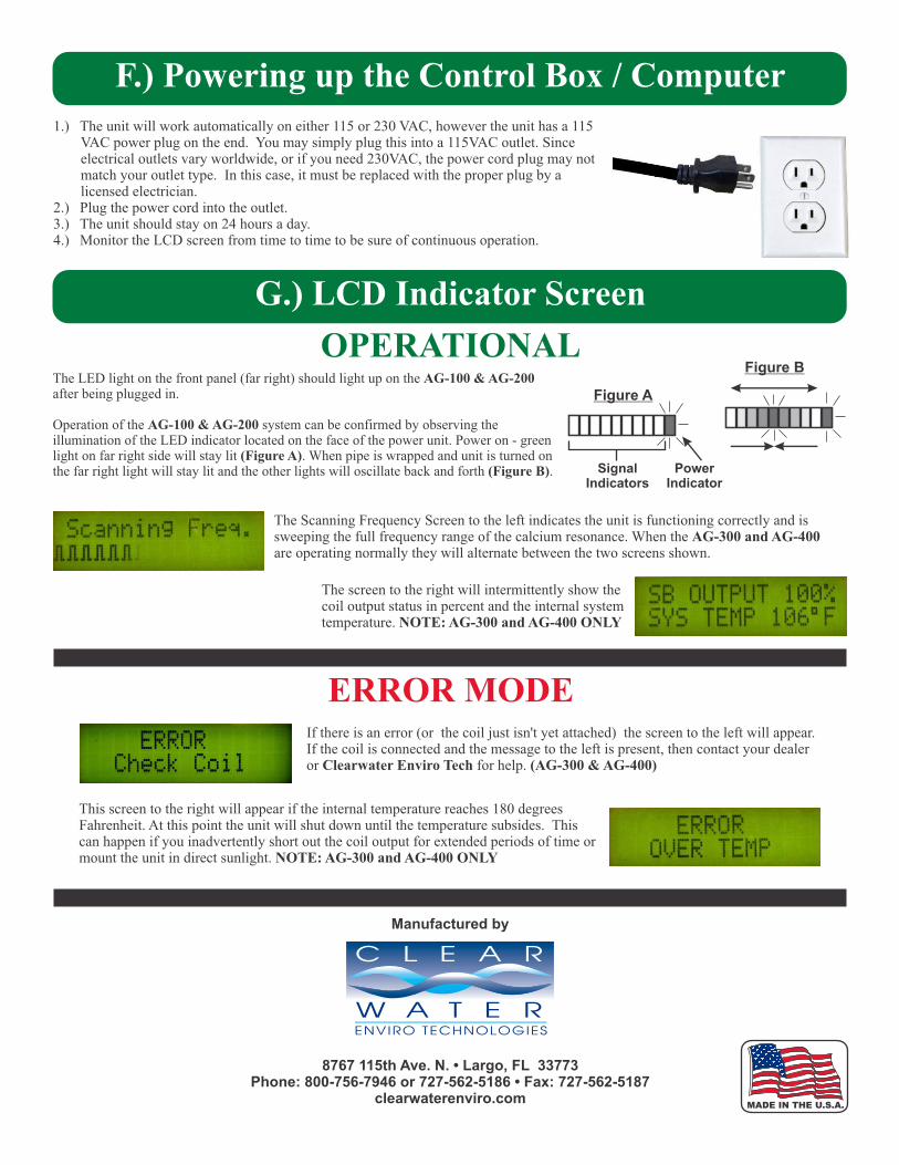
1.) The unit will work automatically on either 115 or 230 VAC, however the unit has a 115 VAC power plug on the end. You may simply plug this into a 115VAC outlet. Since electrical outlets vary worldwide, or if you need 230VAC, the power cord plug may not match your outlet type. In this case, it must be replaced with the proper plug by a licensed electrician.
2.) Plug the power cord into the outlet. 3.) The unit should stay on 24 hours a day.4.) Monitor the LCD screen from time to time to be sure of continuous operation.
OPERATIONAL
ERROR MODE
The Scanning Frequency Screen to the left indicates the unit is functioning correctly and is sweeping the full frequency range of the calcium resonance. When the AG-300 and AG-400 are operating normally they will alternate between the two screens shown.
The screen to the right will intermittently show the coil output status in percent and the internal system temperature. NOTE: AG-300 and AG-400 ONLY
If there is an error (or the coil just isn't yet attached) the screen to the left will appear. If the coil is connected and the message to the left is present, then contact your dealer or Clearwater Enviro Tech for help. (AG-300 & AG-400)
This screen to the right will appear if the internal temperature reaches 180 degrees Fahrenheit. At this point the unit will shut down until the temperature subsides. This can happen if you inadvertently short out the coil output for extended periods of time or mount the unit in direct sunlight. NOTE: AG-300 and AG-400 ONLY
Manufactured by
8767 115th Ave. N. • Largo, FL 33773Phone: 800-756-7946 or 727-562-5186 • Fax: 727-562-5187
clearwaterenviro.comMADE IN THE U.S.A.
Figure A
Figure B
PowerIndicator
SignalIndicators
The LED light on the front panel (far right) should light up on the AG-100 & AG-200 after being plugged in.
Operation of the AG-100 & AG-200 system can be confirmed by observing the illumination of the LED indicator located on the face of the power unit. Power on - green light on far right side will stay lit (Figure A). When pipe is wrapped and unit is turned on the far right light will stay lit and the other lights will oscillate back and forth (Figure B).