Embed Size (px)
Citation preview
Preprint from the Proceedings FIG XXII Congress Washington, D.C. USA, April 2002,CD-ROM, TS5.12 Calibration of Survey Equipment, 11 pages
- 1 -
Scale Determination of Digital Levelling Systems using a
Vertical Comparator
Helmut WOSCHITZ, Fritz K. BRUNNER and Hans HEISTER
Key words: digital levels, staff calibration, system calibration, scale of levelling staff
ABSTRACT
For high precision levelling digital levelling systems use 3m long staffs, where the code isetched on an invar band. The scale of the code is a function of the actual temperature of theinvar band and a constant scale value. The latter is traditionally determined by ‘staffcalibration’.
Using digital levels the scale value could also be influenced by a scale value of thelevel (e.g. aging effects of the CCD). To check the behaviour of the whole levelling system aprocedure known as ‘system calibration’ can be used. Thereby height readings are taken atdifferent positions on the staff and compared with their ‘true values’, which are obtained by alaser interferometer. Critics have expressed their doubts about the usefulness of systemcalibration and they insist on the separate staff calibration.
Therefore we investigated the determination of the scale value of the staff by systemcalibration. For this purpose a staff was calibrated with one of the most accurate facilities forstaff calibration at the Bundeswehr University Munich (UniBwM). A coded invar staff ismounted in a horizontal position and the edges of the code elements are automaticallydetected under control of a laser interferometer. The accuracy of the photoelectric edgedetection is 0.7µm + L*0.4µm, with L being the position on the staff in meter. Thedetermined scale value of the staff was 15.5±0.3ppm.
The system calibration was done with the new vertical comparator at the GrazUniversity of Technology, also controlled by a laser interferometer. The internal precision ofthis vertical comparator is estimated better than ±4µm. For the system calibration the samestaff and a brand-new Trimble DiNi12 digital level were used with the assumption that thisnew level has no scale value. The scale value of the system was determined with15.0±0.3ppm. To prove the assumption (i.e. the DiNi12 has no scale value), further systemcalibration with two Zeiss DiNi11 and the same staff were carried out, yielding the samescale value as obtained with the DiNi12.
We were able to prove, that the system calibration of levelling systems using shortsighting distances is capable of determining the composite scale value of the whole levellingsystem (staff and level) with a standard uncertainty of about 1ppm.
Preprint from the Proceedings FIG XXII Congress Washington, D.C. USA, April 2002,CD-ROM, TS5.12 Calibration of Survey Equipment, 11 pages
- 2 -
CONTACTS
Helmut Woschitz, Fritz K. BrunnerEngineering Geodesy and Measurement Systems, Graz University of TechnologySteyrergasse 308010 GrazAustriaTel. +43/316/873-6321Fax +43/316/873-6820Email: {woschitz, brunner}@ivm.tu-graz.ac.atWeb site: http://www.cis.tugraz.at/ivm/
Hans HeisterInstitute of GeodesyBundeswehr University Munich (UniBwM)D-85577 NeubibergGermanyTel. +49/89/6004-3433Fax +49/89/6004-3904Email: [email protected]
1. INTRODUCTION
Within the last two decades geodetic instruments became fully electronic and as aconsequence smaller, lighter, more automatic and more efficient. This development pushedback the precision mechanics content, and in turn the manufacturing process could bechanged. Now the manufacturer calibrates the equipment and stores specific parameters inthe instrument to appropriately correct the measured quantities. In general, the user does notknow anything about the tolerated imperfections of the mechanics and the associated internalcorrections, and in most cases he does not even want to know about them. As a consequenceof this development the importance of the proper calibration of geodetic equipment isexperiencing a necessary revival (Heister and Staiger, 2001).
1.1 Digital Levels
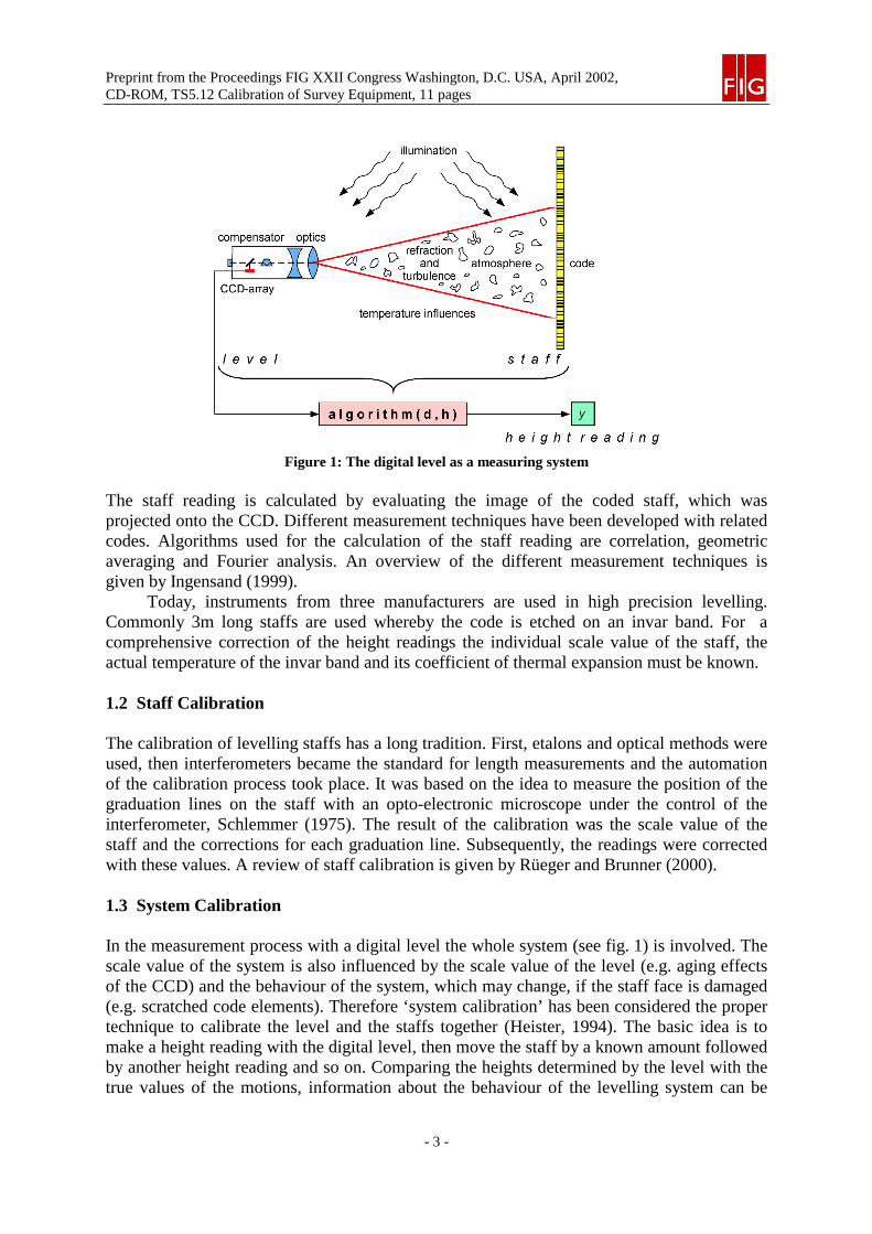
Automation took also place in the field of levelling. Currently there are four different types ofdigital levels on the market (Leica, Sokkia, Topcon and Trimble [former Zeiss]). The codedstaff and the level form the levelling system. The main components of a digital level are theoptical telescope, the compensator, the CCD array, the micro controller and, of course, thesoftware running on it, see fig. 1.
Preprint from the Proceedings FIG XXII Congress Washington, D.C. USA, April 2002,CD-ROM, TS5.12 Calibration of Survey Equipment, 11 pages
- 3 -
Figure 1: The digital level as a measuring system
The staff reading is calculated by evaluating the image of the coded staff, which wasprojected onto the CCD. Different measurement techniques have been developed with relatedcodes. Algorithms used for the calculation of the staff reading are correlation, geometricaveraging and Fourier analysis. An overview of the different measurement techniques isgiven by Ingensand (1999).
Today, instruments from three manufacturers are used in high precision levelling.Commonly 3m long staffs are used whereby the code is etched on an invar band. For acomprehensive correction of the height readings the individual scale value of the staff, theactual temperature of the invar band and its coefficient of thermal expansion must be known.
1.2 Staff Calibration
The calibration of levelling staffs has a long tradition. First, etalons and optical methods wereused, then interferometers became the standard for length measurements and the automationof the calibration process took place. It was based on the idea to measure the position of thegraduation lines on the staff with an opto-electronic microscope under the control of theinterferometer, Schlemmer (1975). The result of the calibration was the scale value of thestaff and the corrections for each graduation line. Subsequently, the readings were correctedwith these values. A review of staff calibration is given by Rüeger and Brunner (2000).
1.3 System Calibration
In the measurement process with a digital level the whole system (see fig. 1) is involved. Thescale value of the system is also influenced by the scale value of the level (e.g. aging effectsof the CCD) and the behaviour of the system, which may change, if the staff face is damaged(e.g. scratched code elements). Therefore ‘system calibration’ has been considered the propertechnique to calibrate the level and the staffs together (Heister, 1994). The basic idea is tomake a height reading with the digital level, then move the staff by a known amount followedby another height reading and so on. Comparing the heights determined by the level with thetrue values of the motions, information about the behaviour of the levelling system can be
Preprint from the Proceedings FIG XXII Congress Washington, D.C. USA, April 2002,CD-ROM, TS5.12 Calibration of Survey Equipment, 11 pages
- 4 -
derived (Brunner and Woschitz, 2001). Obviously it requires to have an adequate ‘machine’to do the movements and to provide the true values.
1.4 Outline
Critics have expressed their doubts about the usefulness of system calibration and insist onthe separate staff calibration. We considered it sufficient to concentrate on the determinationof the scale value of one staff (Zeiss) only, for proving the capability of system calibration.For this purpose a staff calibration was carried out with one of the most accurate facilities atthe Bundeswehr University Munich (UniBwM). The system calibration was carried out at theGraz University of Technology (TUG) with a Trimble DiNi12. The two calibration facilitiesare described in section 2. A description of the test procedure and the results are the main partof section 3. The analysis of the independently derived results is done in section 4.
2. DESCRIPTION OF CALIBRATION FACILITIES
2.1 Horizontal Comparator for Staff Scale Determination
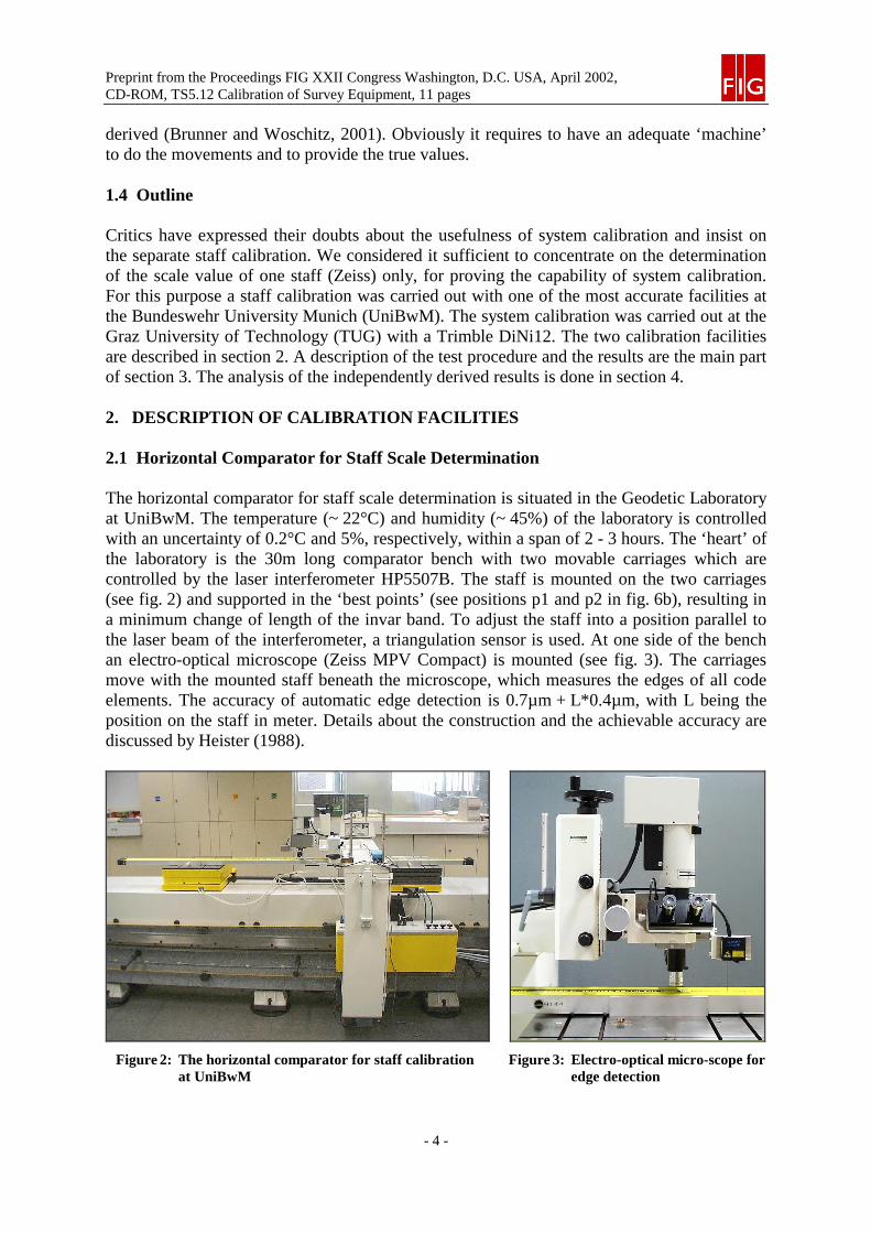
The horizontal comparator for staff scale determination is situated in the Geodetic Laboratoryat UniBwM. The temperature (~ 22°C) and humidity (~ 45%) of the laboratory is controlledwith an uncertainty of 0.2°C and 5%, respectively, within a span of 2 - 3 hours. The ‘heart’ ofthe laboratory is the 30m long comparator bench with two movable carriages which arecontrolled by the laser interferometer HP5507B. The staff is mounted on the two carriages(see fig. 2) and supported in the ‘best points’ (see positions p1 and p2 in fig. 6b), resulting ina minimum change of length of the invar band. To adjust the staff into a position parallel tothe laser beam of the interferometer, a triangulation sensor is used. At one side of the benchan electro-optical microscope (Zeiss MPV Compact) is mounted (see fig. 3). The carriagesmove with the mounted staff beneath the microscope, which measures the edges of all codeelements. The accuracy of automatic edge detection is 0.7µm + L*0.4µm, with L being theposition on the staff in meter. Details about the construction and the achievable accuracy arediscussed by Heister (1988).
Figure 2: The horizontal comparator for staff calibrationat UniBwM
Figure 3: Electro-optical micro-scope foredge detection
Preprint from the Proceedings FIG XXII Congress Washington, D.C. USA, April 2002,CD-ROM, TS5.12 Calibration of Survey Equipment, 11 pages
- 5 -
2.2 Vertical Comparator for System Calibration
Within the last decade the Geodetic Metrology Laboratory (GML) was established at theGraz University of Technology. The laboratory is climatically controlled with a temperatureof 22.0°C ± 0.5°C and a humidity of 50% ± 10%. One of the calibration facilities in the GMLis its vertical comparator.
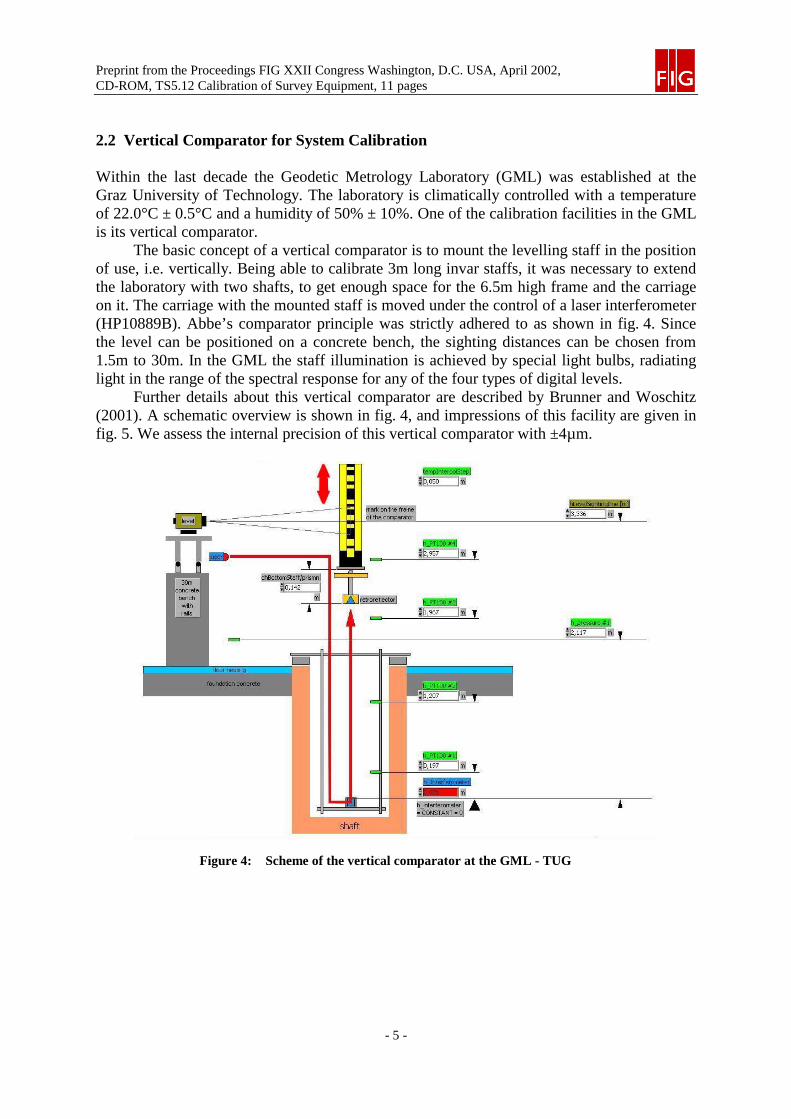
The basic concept of a vertical comparator is to mount the levelling staff in the positionof use, i.e. vertically. Being able to calibrate 3m long invar staffs, it was necessary to extendthe laboratory with two shafts, to get enough space for the 6.5m high frame and the carriageon it. The carriage with the mounted staff is moved under the control of a laser interferometer(HP10889B). Abbe’s comparator principle was strictly adhered to as shown in fig. 4. Sincethe level can be positioned on a concrete bench, the sighting distances can be chosen from1.5m to 30m. In the GML the staff illumination is achieved by special light bulbs, radiatinglight in the range of the spectral response for any of the four types of digital levels.
Further details about this vertical comparator are described by Brunner and Woschitz(2001). A schematic overview is shown in fig. 4, and impressions of this facility are given infig. 5. We assess the internal precision of this vertical comparator with ±4µm.
Figure 4: Scheme of the vertical comparator at the GML - TUG
Preprint from the Proceedings FIG XXII Congress Washington, D.C. USA, April 2002,CD-ROM, TS5.12 Calibration of Survey Equipment, 11 pages
- 6 -
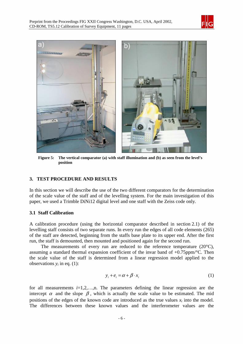
Figure 5: The vertical comparator (a) with staff illumination and (b) as seen from the level’sposition
3. TEST PROCEDURE AND RESULTS
In this section we will describe the use of the two different comparators for the determinationof the scale value of the staff and of the levelling system. For the main investigation of thispaper, we used a Trimble DiNi12 digital level and one staff with the Zeiss code only.
3.1 Staff Calibration
A calibration procedure (using the horizontal comparator described in section 2.1) of thelevelling staff consists of two separate runs. In every run the edges of all code elements (265)of the staff are detected, beginning from the staffs base plate to its upper end. After the firstrun, the staff is demounted, then mounted and positioned again for the second run.
The measurements of every run are reduced to the reference temperature (20°C),assuming a standard thermal expansion coefficient of the invar band of +0.75ppm/°C. Thenthe scale value of the staff is determined from a linear regression model applied to theobservations yi in eq. (1):
iii xey ⋅+=+ βα (1)
for all measurements i=1,2,…,n. The parameters defining the linear regression are theintercept α and the slope β , which is actually the scale value to be estimated. The midpositions of the edges of the known code are introduced as the true values xi into the model.The differences between these known values and the interferometer values are the
Preprint from the Proceedings FIG XXII Congress Washington, D.C. USA, April 2002,CD-ROM, TS5.12 Calibration of Survey Equipment, 11 pages
- 7 -
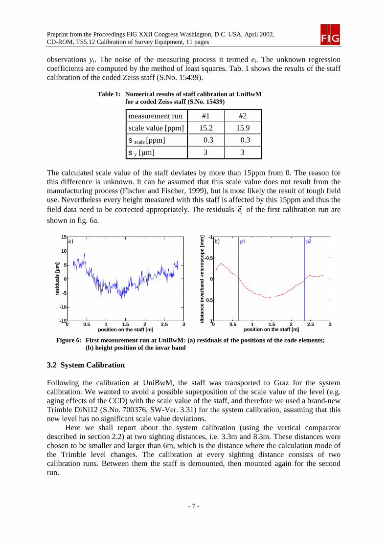
observations yi. The noise of the measuring process it termed ei. The unknown regressioncoefficients are computed by the method of least squares. Tab. 1 shows the results of the staffcalibration of the coded Zeiss staff (S.No. 15439).
Table 1: Numerical results of staff calibration at UniBwMfor a coded Zeiss staff (S.No. 15439)
measurement run #1 #2
scale value [ppm] 15.2 15.9
sscale [ppm] 0.3 0.3
sy [µm] 3 3
The calculated scale value of the staff deviates by more than 15ppm from 0. The reason forthis difference is unknown. It can be assumed that this scale value does not result from themanufacturing process (Fischer and Fischer, 1999), but is most likely the result of tough fielduse. Nevertheless every height measured with this staff is affected by this 15ppm and thus thefield data need to be corrected appropriately. The residuals ie~ of the first calibration run are
shown in fig. 6a.
0 0.5 1 1.5 2 2.5 3-15
-10
-5
0
5
10
15
position on the staff [m]
resi
du
als
[µm
]
a)
0 0.5 1 1.5 2 2.5 3
-1
-0.5
0
0.5
1
position on the staff [m]
dis
tan
cein
varb
and
-mic
rosc
op
e[m
m]
p1 p2b)
Figure 6: First measurement run at UniBwM: (a) residuals of the positions of the code elements;(b) height position of the invar band
3.2 System Calibration
Following the calibration at UniBwM, the staff was transported to Graz for the systemcalibration. We wanted to avoid a possible superposition of the scale value of the level (e.g.aging effects of the CCD) with the scale value of the staff, and therefore we used a brand-newTrimble DiNi12 (S.No. 700376, SW-Ver. 3.31) for the system calibration, assuming that thisnew level has no significant scale value deviations.
Here we shall report about the system calibration (using the vertical comparatordescribed in section 2.2) at two sighting distances, i.e. 3.3m and 8.3m. These distances werechosen to be smaller and larger than 6m, which is the distance where the calculation mode ofthe Trimble level changes. The calibration at every sighting distance consists of twocalibration runs. Between them the staff is demounted, then mounted again for the secondrun.
Preprint from the Proceedings FIG XXII Congress Washington, D.C. USA, April 2002,CD-ROM, TS5.12 Calibration of Survey Equipment, 11 pages
- 8 -
To avoid systematic errors of the level, which usually occur at the ends of a staff, thecalibration was carried out between 0.15m and 2.85m. Every calibration run consisted of twoparts: (a) the forward measurements from the lower to the upper end of the staff and (b) thebackward measurements, from the upper to the lower end. The backward measurements wereshifted by half of the sampling interval (Rüeger and Brunner, 2000). The sampling intervalwas chosen rather arbitrarily as I/12, where I is the length of the CCD projected to the code ata sighting distance of 3m. Note, that Rüeger and Brunner (2000) suggested to use I/3. In ourcase I/12 equals 21.833mm. Both measurements, (a) and (b) together yielded 247 positions atthe staff. Every position was calculated as the mean of three individual height readings. Whenthe calibration of the staff was finished, the staff was removed and mounted again on thecomparator, followed by the second calibration run.
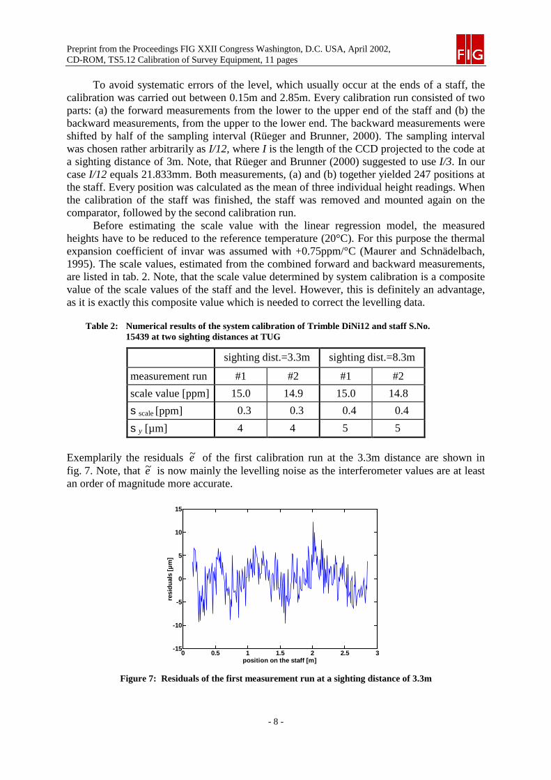
Before estimating the scale value with the linear regression model, the measuredheights have to be reduced to the reference temperature (20°C). For this purpose the thermalexpansion coefficient of invar was assumed with +0.75ppm/°C (Maurer and Schnädelbach,1995). The scale values, estimated from the combined forward and backward measurements,are listed in tab. 2. Note, that the scale value determined by system calibration is a compositevalue of the scale values of the staff and the level. However, this is definitely an advantage,as it is exactly this composite value which is needed to correct the levelling data.
Table 2: Numerical results of the system calibration of Trimble DiNi12 and staff S.No.15439 at two sighting distances at TUG
sighting dist.=3.3m sighting dist.=8.3m
measurement run #1 #2 #1 #2
scale value [ppm] 15.0 14.9 15.0 14.8
sscale [ppm] 0.3 0.3 0.4 0.4
sy [µm] 4 4 5 5
Exemplarily the residuals e~ of the first calibration run at the 3.3m distance are shown infig. 7. Note, that e~ is now mainly the levelling noise as the interferometer values are at leastan order of magnitude more accurate.
0 0.5 1 1.5 2 2.5 3-15
-10
-5
0
5
10
15
position on the staff [m]
resi
du
als
[µm
]
Figure 7: Residuals of the first measurement run at a sighting distance of 3.3m
Preprint from the Proceedings FIG XXII Congress Washington, D.C. USA, April 2002,CD-ROM, TS5.12 Calibration of Survey Equipment, 11 pages
- 9 -
4. ANALYSIS OF THE RESULTS
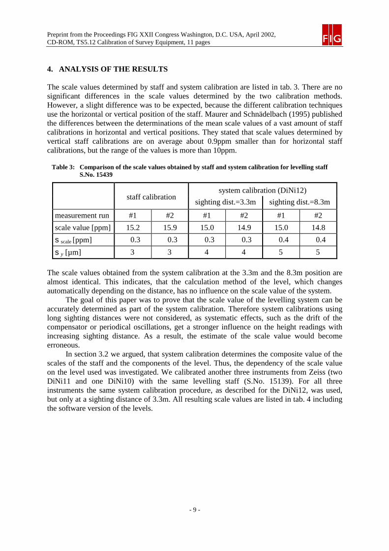
The scale values determined by staff and system calibration are listed in tab. 3. There are nosignificant differences in the scale values determined by the two calibration methods.However, a slight difference was to be expected, because the different calibration techniquesuse the horizontal or vertical position of the staff. Maurer and Schnädelbach (1995) publishedthe differences between the determinations of the mean scale values of a vast amount of staffcalibrations in horizontal and vertical positions. They stated that scale values determined byvertical staff calibrations are on average about 0.9ppm smaller than for horizontal staffcalibrations, but the range of the values is more than 10ppm.
Table 3: Comparison of the scale values obtained by staff and system calibration for levelling staffS.No. 15439
system calibration (DiNi12)staff calibration
sighting dist.=3.3m sighting dist.=8.3m
measurement run #1 #2 #1 #2 #1 #2
scale value [ppm] 15.2 15.9 15.0 14.9 15.0 14.8
sscale [ppm] 0.3 0.3 0.3 0.3 0.4 0.4
sy [µm] 3 3 4 4 5 5
The scale values obtained from the system calibration at the 3.3m and the 8.3m position arealmost identical. This indicates, that the calculation method of the level, which changesautomatically depending on the distance, has no influence on the scale value of the system.
The goal of this paper was to prove that the scale value of the levelling system can beaccurately determined as part of the system calibration. Therefore system calibrations usinglong sighting distances were not considered, as systematic effects, such as the drift of thecompensator or periodical oscillations, get a stronger influence on the height readings withincreasing sighting distance. As a result, the estimate of the scale value would becomeerroneous.
In section 3.2 we argued, that system calibration determines the composite value of thescales of the staff and the components of the level. Thus, the dependency of the scale valueon the level used was investigated. We calibrated another three instruments from Zeiss (twoDiNi11 and one DiNi10) with the same levelling staff (S.No. 15139). For all threeinstruments the same system calibration procedure, as described for the DiNi12, was used,but only at a sighting distance of 3.3m. All resulting scale values are listed in tab. 4 includingthe software version of the levels.
Preprint from the Proceedings FIG XXII Congress Washington, D.C. USA, April 2002,CD-ROM, TS5.12 Calibration of Survey Equipment, 11 pages
- 10 -
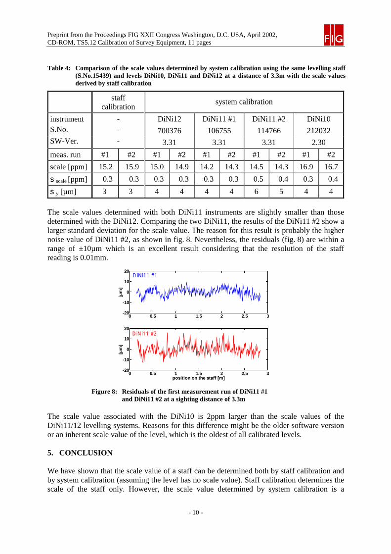
Table 4: Comparison of the scale values determined by system calibration using the same levelling staff(S.No.15439) and levels DiNi10, DiNi11 and DiNi12 at a distance of 3.3m with the scale valuesderived by staff calibration
staffcalibration
system calibration
instrument - DiNi12 DiNi11 #1 DiNi11 #2 DiNi10S.No. - 700376 106755 114766 212032SW-Ver. - 3.31 3.31 3.31 2.30
meas. run #1 #2 #1 #2 #1 #2 #1 #2 #1 #2
scale [ppm] 15.2 15.9 15.0 14.9 14.2 14.3 14.5 14.3 16.9 16.7
sscale [ppm] 0.3 0.3 0.3 0.3 0.3 0.3 0.5 0.4 0.3 0.4
sy [µm] 3 3 4 4 4 4 6 5 4 4
The scale values determined with both DiNi11 instruments are slightly smaller than thosedetermined with the DiNi12. Comparing the two DiNi11, the results of the DiNi11 #2 show alarger standard deviation for the scale value. The reason for this result is probably the highernoise value of DiNi11 #2, as shown in fig. 8. Nevertheless, the residuals (fig. 8) are within arange of ±10µm which is an excellent result considering that the resolution of the staffreading is 0.01mm.
0 0.5 1 1.5 2 2.5 3-20
-10
0
10
20
[µm
]
position on the staff [m]
DiNi11 #2
0 0.5 1 1.5 2 2.5 3-20
-10
0
10
20
[µm
]
DiNi11 #1
Figure 8: Residuals of the first measurement run of DiNi11 #1and DiNi11 #2 at a sighting distance of 3.3m
The scale value associated with the DiNi10 is 2ppm larger than the scale values of theDiNi11/12 levelling systems. Reasons for this difference might be the older software versionor an inherent scale value of the level, which is the oldest of all calibrated levels.
5. CONCLUSION
We have shown that the scale value of a staff can be determined both by staff calibration andby system calibration (assuming the level has no scale value). Staff calibration determines thescale of the staff only. However, the scale value determined by system calibration is a
Preprint from the Proceedings FIG XXII Congress Washington, D.C. USA, April 2002,CD-ROM, TS5.12 Calibration of Survey Equipment, 11 pages
- 11 -
composite value of the staff scale and an additional scale, caused by the level. This isdefinitely an advantage, as it is exactly this composite value which is needed to correct thelevelling data.
Once the scale value is determined, the measured heights, hmeas, have to be corrected forthe following systematic effects
)]tt(m1[hh refinvinvsysmeascorr −⋅++⋅= α (2)
where msys is the scale value of the levelling system (i.e. level AND staff), invα is thecoefficient of thermal expansion of invar, tinv the temperature of the invar band of the staff,and tref the reference temperature (generally 20°C) for which msys was determined.
In our opinion, it is not necessary to determine the coefficient of thermal expansion forevery individual levelling staff. It seems to be sufficient to determine the coefficientrepresentative for a batch of staffs.
We were able to prove, that system calibration of levelling systems using short sightingdistances is capable to determine the composite scale values of the whole levelling systemwith a standard uncertainty of about 1ppm.
REFERENCES
Brunner, F.K., Woschitz, H. (2001): Kalibrierung von Messsystemen: Grundlagen undBeispiele. In Heister H. and Staiger R., (ed.) Qualitätsmanagement in der GeodätischenMesstechnik. Konrad Wittwer Verlag, DVW Schriftenreihe 42: 70-90.
Fischer, T., Fischer, W. (1999): Manufacturing of High Precission Levelling Rods. In Lilje,M. (ed.) The importance of heights. FIG, Gävle, Sweden: 223-228.
Heister, H. (1988): Zur automatisierten Kalibrierung geodätischer Längenmessinstrumente.Universität der Bundeswehr München, Schriftenreihe 27, Neubiberg. 210 pages.
Heister, H. (1994): Zur Überprüfung von Präzisions-Nivellierlatten mit digitalem Code.Universität der Bundeswehr München, Schriftenreihe Nr. 46: 95-101.
Heister, H. and Staiger R. (2001): Qualitätsmanagement in der Geodätischen Messtechnik.Konrad Wittwer Verlag, DVW Schriftenreihe 42.
Ingensand, H. (1999): The evolution of digital levelling techniques - limitations and newsolutions. In Lilje, M. (ed.) The importance of heights. FIG, Gävle, Sweden: 59-68.
Maurer, W., Schnädelbach, K. (1995): Laserinterferometry - Ten Years Experience inCalibrating Invar Levelling Staffs. Proc., First Int. Symp. Appl. Laser Techniques inGeodesy and Mine Surveying, Ljubljana, Sept. 1995, 9 p.
Rüeger, J.M., Brunner, F.K. (2000): On System Calibration and Type Testing of DigitalLevels. Z. f. Vermessungswesen 125: 120–130.
Schlemmer, H. (1975): Laser-Interferenzkomparator zur Prüfung von Präzisionsnivellier-latten. Verlag der Bayrischen Akademie der Wissenschaften. DGK Reihe C, Bd. 210.