Embed Size (px)
Citation preview
Applications & Tools
Answers for industry.
Cover
Configuring Secure Remote Maintenance Access with the Aid of the SCALANCE S623 SCALANCE S623
Application Description March 2013
2 VPN S623
V1.0, Entry ID: 22056713
Cop
yrig
ht
Sie
men
s A
G 2
013
All
right
s re
serv
ed
Siemens Industry Online Support This entry is taken from Siemens Industry Online Support. The following link takes you directly to the download page of this document: http://support.automation.siemens.com/WW/view/en/22056713 Caution The functions and solutions described in this entry predominantly confine themselves to the realization of the automation task. Please also take into account that corresponding protective measures have to be taken in the context of Industrial Security when connecting your equipment to other parts of the plant, the enterprise network or the Internet. For more information, please refer to Entry ID 50203404. http://support.automation.siemens.com/WW/view/en/50203404 Please also actively use our Technical Forum in Siemens Industry Online Support regarding this subject. Share your questions, suggestions or problems and discuss them with our strong forum community: http://www.siemens.com/forum-applications
VPN S623 V1.0, Entry ID: 22056713 3
Cop
yrig
ht
Sie
men
s A
G 2
013
All
right
s re
serv
ed
s
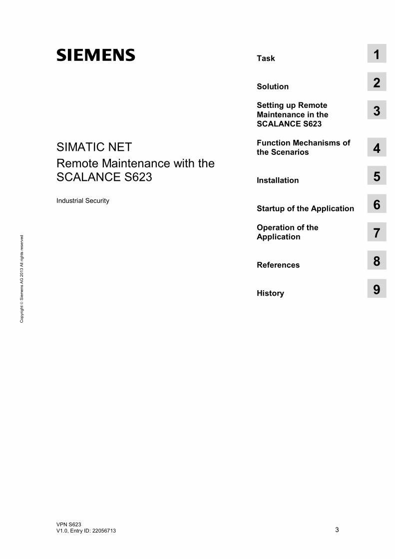
SIMATIC NET Remote Maintenance with the SCALANCE S623 Industrial Security
Task 1
Solution 2
Setting up Remote Maintenance in the SCALANCE S623
3 Function Mechanisms of the Scenarios
4
Installation 5
Startup of the Application 6
Operation of the Application
7
References 8
History 9

Warranty and Liability
4 VPN S623
V1.0, Entry ID: 22056713
Cop
yrig
ht
Sie
men
s A
G 2
013
All
right
s re
serv
ed
Warranty and Liability
Note The Application Examples are not binding and do not claim to be complete regarding the circuits shown, equipping and any eventuality. The Application Examples do not represent customer-specific solutions. They are only intended to provide support for typical applications. You are responsible for ensuring that the described products are used correctly. These Application Examples do not relieve you of the responsibility to use safe practices in application, installation, operation and maintenance. When using these Application Examples, you recognize that we cannot be made liable for any damage/claims beyond the liability clause described. We reserve the right to make changes to these Application Examples at any time without prior notice. If there are any deviations between the recommendations provided in these Application Examples and other Siemens publications – e.g. Catalogs – the contents of the other documents have priority.
We do not accept any liability for the information contained in this document.
Any claims against us – based on whatever legal reason – resulting from the use of the examples, information, programs, engineering and performance data etc., described in this Application Example shall be excluded. Such an exclusion shall not apply in the case of mandatory liability, e.g. under the German Product Liability Act (“Produkthaftungsgesetz”), in case of intent, gross negligence, or injury of life, body or health, guarantee for the quality of a product, fraudulent concealment of a deficiency or breach of a condition which goes to the root of the contract (“wesentliche Vertragspflichten”). The damages for a breach of a substantial contractual obligation are, however, limited to the foreseeable damage, typical for the type of contract, except in the event of intent or gross negligence or injury to life, body or health. The above provisions do not imply a change of the burden of proof to your detriment. Any form of duplication or distribution of these Application Examples or excerpts hereof is prohibited without the expressed consent of Siemens Industry Sector.
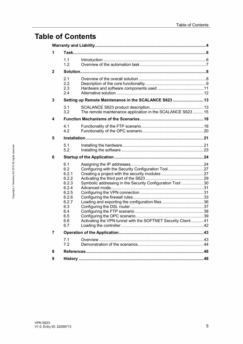
Table of Contents
VPN S623 V1.0, Entry ID: 22056713 5
Cop
yrig
ht
Sie
men
s A
G 2
013
All
right
s re
serv
ed
Table of Contents Warranty and Liability .............................................................................................. 4 1 Task................................................................................................................. 6
1.1 Introduction ....................................................................................... 6 1.2 Overview of the automation task ........................................................ 7
2 Solution........................................................................................................... 8 2.1 Overview of the overall solution ......................................................... 8 2.2 Description of the core functionality .................................................... 9 2.3 Hardware and software components used ....................................... 11 2.4 Alternative solution .......................................................................... 12
3 Setting up Remote Maintenance in the SCALANCE S623 .......................... 13 3.1 SCALANCE S623 product description.............................................. 13 3.2 The remote maintenance application in the SCALANCE S623 ......... 15
4 Function Mechanisms of the Scenarios ...................................................... 18 4.1 Functionality of the FTP scenario ..................................................... 18 4.2 Functionality of the OPC scenario .................................................... 20
5 Installation .................................................................................................... 21 5.1 Installing the hardware ..................................................................... 21 5.2 Installing the software ...................................................................... 23
6 Startup of the Application ............................................................................ 24 6.1 Assigning the IP addresses.............................................................. 24 6.2 Configuring with the Security Configuration Tool .............................. 27 6.2.1 Creating a project with the security modules .................................... 27 6.2.2 Activating the third port of the S623 ................................................. 29 6.2.3 Symbolic addressing in the Security Configuration Tool ................... 30 6.2.4 Advanced mode............................................................................... 31 6.2.5 Configuring the VPN connection ...................................................... 31 6.2.6 Configuring the firewall rules ............................................................ 33 6.2.7 Loading and exporting the configuration files ................................... 36 6.3 Configuring the DSL router .............................................................. 37 6.4 Configuring the FTP scenario .......................................................... 38 6.5 Configuring the OPC scenario.......................................................... 39 6.6 Activating the VPN tunnel with the SOFTNET Security Client ........... 41 6.7 Loading the controller ...................................................................... 42
7 Operation of the Application ........................................................................ 43 7.1 Overview ......................................................................................... 43 7.2 Demonstration of the scenarios........................................................ 44
8 References .................................................................................................... 48 9 History .......................................................................................................... 48
1 Task 1.1 Introduction
6 VPN S623
V1.0, Entry ID: 22056713
Cop
yrig
ht
Sie
men
s A
G 2
013
All
right
s re
serv
ed
1 Task 1.1 Introduction
More and more often, Ethernet connections extend all the way to the field level. For plant automation, this offers many advantages such as remote diagnostics and remote maintenance. Efficiency regarding the time required and associated costs is significantly higher than sending service staff to plants around the world. Faults can be detected and eliminated much more quickly. This reduces machine downtimes and increases their availability. At the same time, however, production processes that were secure in the past are now open to attack from both the outside and inside. Only an approach that combines security mechanisms and a comprehensive understanding of automation can provide reliable protection. To maintain security in automation, it is therefore necessary to use a security concept that is specifically tailored to the requirements of automation. For remote access, the security components from Siemens and today’s Internet access mechanisms (radio, broadband) make a successful combination.
1 Task 1.2 Overview of the automation task
VPN S623 V1.0, Entry ID: 22056713 7
Cop
yrig
ht
Sie
men
s A
G 2
013
All
right
s re
serv
ed
1.2 Overview of the automation task
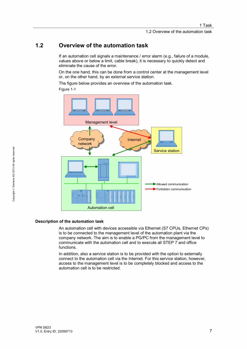
If an automation cell signals a maintenance / error alarm (e.g., failure of a module, values above or below a limit, cable break), it is necessary to quickly detect and eliminate the cause of the error. On the one hand, this can be done from a control center at the management level or, on the other hand, by an external service station. The figure below provides an overview of the automation task. Figure 1-1
InternetInternet
Automation cell
Management level
Service station
Allowed communicationForbidden communication
Company network
Description of the automation task An automation cell with devices accessible via Ethernet (S7 CPUs, Ethernet CPs) is to be connected to the management level of the automation plant via the company network. The aim is to enable a PG/PC from the management level to communicate with the automation cell and to execute all STEP 7 and office functions. In addition, also a service station is to be provided with the option to externally connect to the automation cell via the Internet. For this service station, however, access to the management level is to be completely blocked and access to the automation cell is to be restricted.
2 Solution 2.1 Overview of the overall solution
8 VPN S623
V1.0, Entry ID: 22056713
Cop
yrig
ht
Sie
men
s A
G 2
013
All
right
s re
serv
ed
2 Solution 2.1 Overview of the overall solution
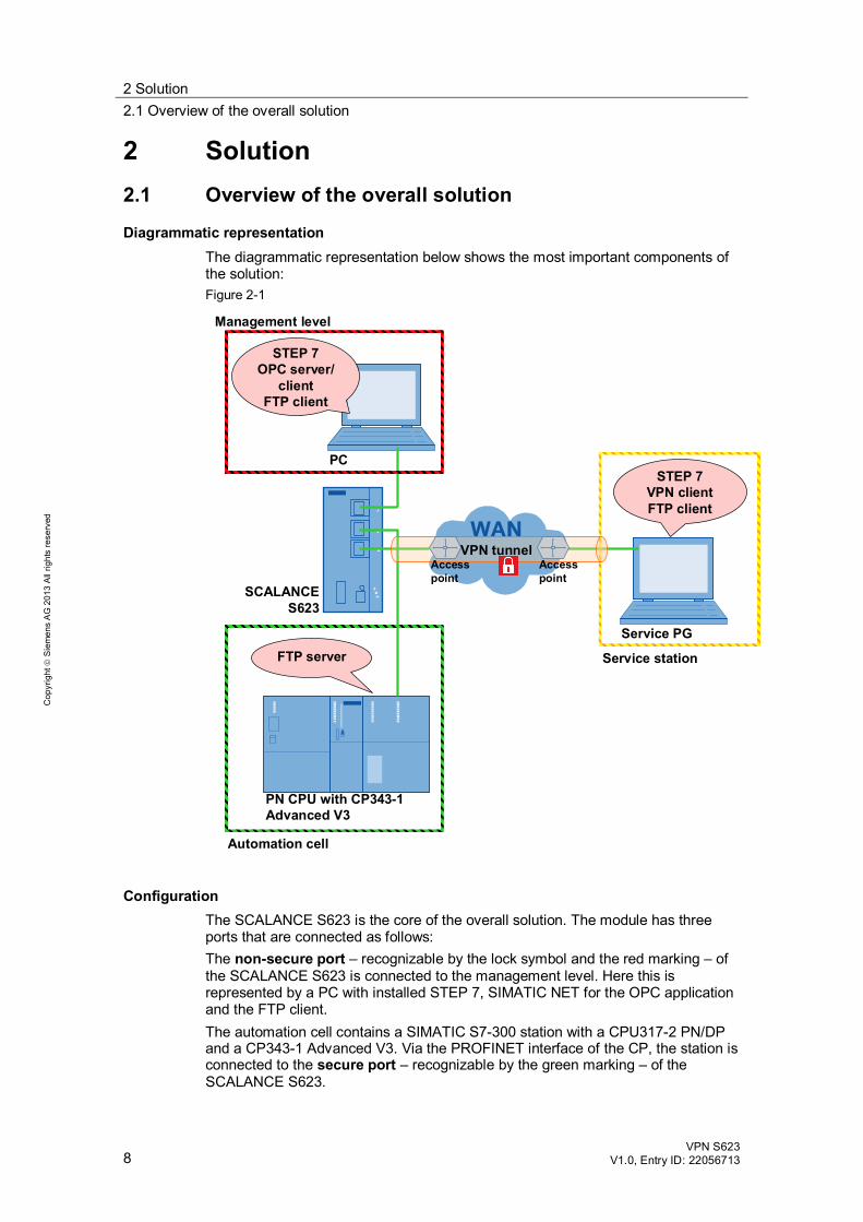
Diagrammatic representation The diagrammatic representation below shows the most important components of the solution: Figure 2-1
SCALANCE S623
PN CPU with CP343-1 Advanced V3
Service PG
PC
FTP server
STEP 7VPN clientFTP client
STEP 7OPC server/
clientFTP client
Automation cell
Management level
Service station
VPN tunnelAccesspoint
Accesspoint
Configuration The SCALANCE S623 is the core of the overall solution. The module has three ports that are connected as follows: The non-secure port – recognizable by the lock symbol and the red marking – of the SCALANCE S623 is connected to the management level. Here this is represented by a PC with installed STEP 7, SIMATIC NET for the OPC application and the FTP client. The automation cell contains a SIMATIC S7-300 station with a CPU317-2 PN/DP and a CP343-1 Advanced V3. Via the PROFINET interface of the CP, the station is connected to the secure port – recognizable by the green marking – of the SCALANCE S623.
2 Solution 2.2 Description of the core functionality
VPN S623 V1.0, Entry ID: 22056713 9
Cop
yrig
ht
Sie
men
s A
G 2
013
All
right
s re
serv
ed
The third port of the SCALANCE S623 is a DMZ port – recognizable by the lock symbol and the yellow marking. This interface is the access for the service station for remote maintenance purposes. The service PG is equipped with the STEP 7 software, a VPN client (SOFTNET Security Client) and an FTP client.
Scope This application does not include basic information on Industrial Ethernet explanations of the basic terms in the context of Industrial Security detailed information on firewall and VPN technology.
Basic knowledge of these topics is required.
2.2 Description of the core functionality
SCALANCE S623 The core of this application is the SCALANCE S623 Security Module. This module is part of the Siemens security concept and was developed specifically for industrial automation. It can be configured as a firewall and / or VPN end point and thus be used to protect automation cells and components. With its three network ports, the module additionally offers the option to set up a demilitarized zone or use the additional port for remote maintenance purposes.
SOFTNET Security Client The SOFTNET Security Client is a software-based Industrial Security component. It allows PGs / PCs to establish a secure connection to the installed SCALANCE S modules.
Industrial Security with VPN For remote maintenance or diagnostics via a public, unsecured network, reliable security has the highest priority when transferring data. Confidential and sensitive information must not be sent through the Internet as plain text and therefore be read and / or manipulated by unauthorized third parties. To ensure secure and reliable data transfer, this application uses a VPN solution. VPN is the abbreviation for virtual private network. It combines two separate networks into one closed logical network. A firewall is used for controlled communication between the networks. Appropriate firewall rules allow you to grant the service station only access to the automation cell but not to the management level. This solution is configured using the Security Configuration Tool.
Description of the user scenarios The table below shows the scenarios presented in this application. Appropriate firewall rules in the SCALANCE S module ensure that only scenarios for defined networks are enabled.
2 Solution 2.2 Description of the core functionality
10 VPN S623
V1.0, Entry ID: 22056713
Cop
yrig
ht
Sie
men
s A
G 2
013
All
right
s re
serv
ed
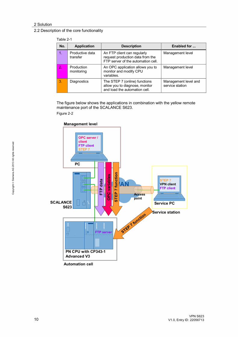
Table 2-1
No. Application Description Enabled for ...
1. Productive data transfer
An FTP client can regularly request production data from the FTP server of the automation cell.
Management level
2. Production monitoring
An OPC application allows you to monitor and modify CPU variables.
Management level
3. Diagnostics The STEP 7 (online) functions allow you to diagnose, monitor and load the automation cell.
Management level and service station
The figure below shows the applications in combination with the yellow remote maintenance port of the SCALANCE S623. Figure 2-2
SCALANCE S623
PN CPU with CP343-1 Advanced V3
Service PC
PC
Automation cell
Management level
Service station
OPC server / clientFTP clientSTEP 7
STEP 7VPN clientFTP client
FTP server STEP 7 functio
n
FTP
data
OPC
var
iabl
es
STEP
7 fu
nctio
n
Accesspoint
2 Solution 2.3 Hardware and software components used
VPN S623 V1.0, Entry ID: 22056713 11
Cop
yrig
ht
Sie
men
s A
G 2
013
All
right
s re
serv
ed
Advantages of this solution Flexible, reaction-free and protocol-independent (layer 2 and higher, according
to IEEE 802.3) protection against data espionage and data manipulation. User-friendly and easy configuration and administration without special security
knowledge. Scalable security functionality. Access protection for any devices in Ethernet networks. Secure remote access via the Internet (e.g., with a DSL modem) can be
implemented.
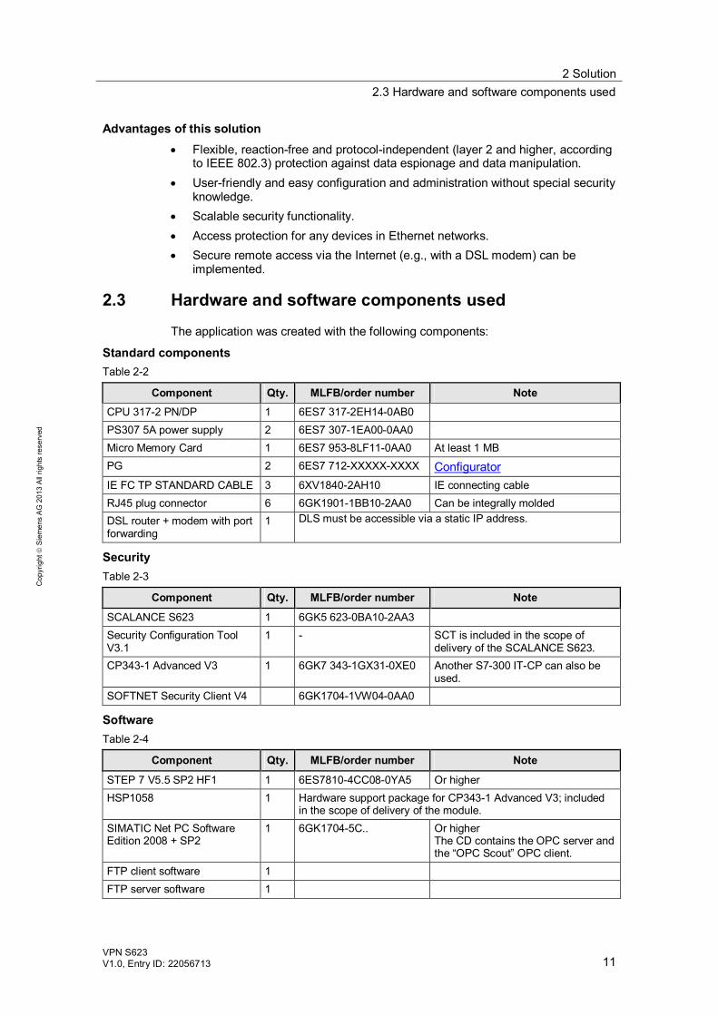
2.3 Hardware and software components used
The application was created with the following components:
Standard components Table 2-2
Component Qty. MLFB/order number Note CPU 317-2 PN/DP 1 6ES7 317-2EH14-0AB0 PS307 5A power supply 2 6ES7 307-1EA00-0AA0 Micro Memory Card 1 6ES7 953-8LF11-0AA0 At least 1 MB PG 2 6ES7 712-XXXXX-XXXX Configurator IE FC TP STANDARD CABLE 3 6XV1840-2AH10 IE connecting cable RJ45 plug connector 6 6GK1901-1BB10-2AA0 Can be integrally molded DSL router + modem with port forwarding
1 DLS must be accessible via a static IP address.
Security Table 2-3
Component Qty. MLFB/order number Note
SCALANCE S623 1 6GK5 623-0BA10-2AA3 Security Configuration Tool V3.1
1 - SCT is included in the scope of delivery of the SCALANCE S623.
CP343-1 Advanced V3 1 6GK7 343-1GX31-0XE0 Another S7-300 IT-CP can also be used.
SOFTNET Security Client V4 6GK1704-1VW04-0AA0
Software Table 2-4
Component Qty. MLFB/order number Note
STEP 7 V5.5 SP2 HF1 1 6ES7810-4CC08-0YA5 Or higher HSP1058 1 Hardware support package for CP343-1 Advanced V3; included
in the scope of delivery of the module. SIMATIC Net PC Software Edition 2008 + SP2
1 6GK1704-5C.. Or higher The CD contains the OPC server and the “OPC Scout” OPC client.
FTP client software 1 FTP server software 1
2 Solution 2.4 Alternative solution
12 VPN S623
V1.0, Entry ID: 22056713
Cop
yrig
ht
Sie
men
s A
G 2
013
All
right
s re
serv
ed
Sample files and projects The following list contains all files and projects that are used in this example.
Table 2-5
Component Note 22056713_VPN_S623_DOKU_V10_e.pdf This document. 22056713_VPN_S623_CODE_V10.zip This zip file contains the STEP 7 project.
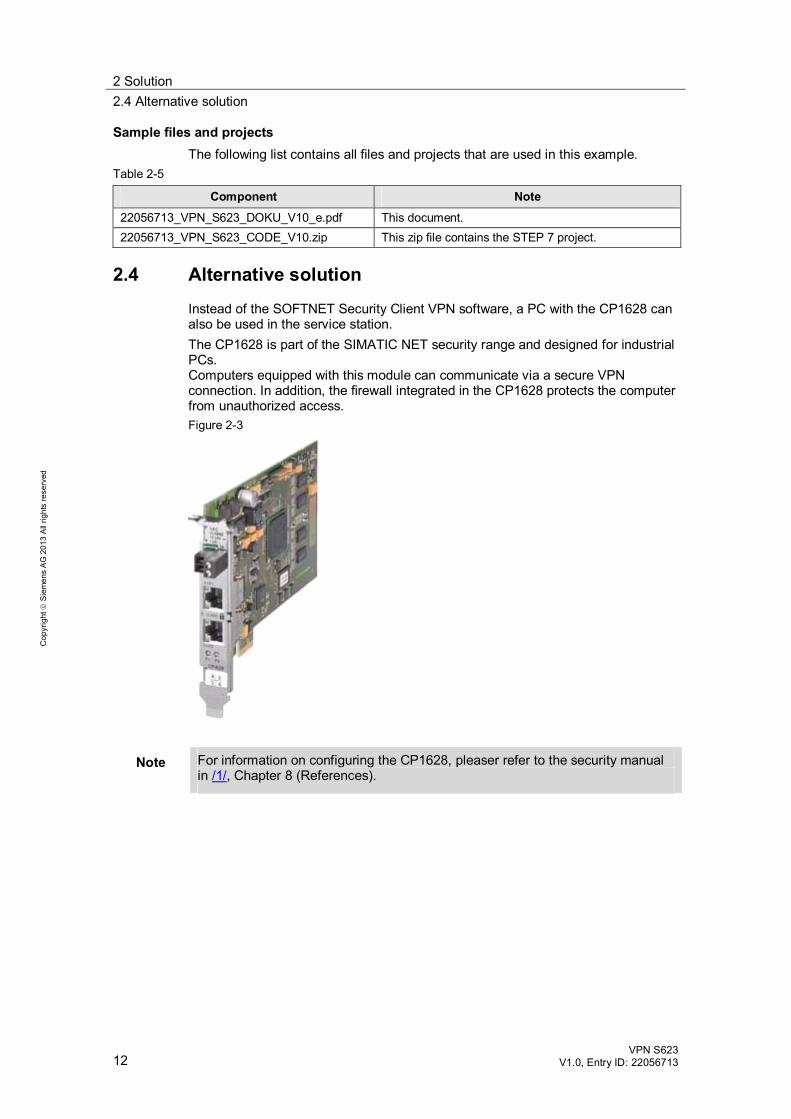
2.4 Alternative solution
Instead of the SOFTNET Security Client VPN software, a PC with the CP1628 can also be used in the service station. The CP1628 is part of the SIMATIC NET security range and designed for industrial PCs. Computers equipped with this module can communicate via a secure VPN connection. In addition, the firewall integrated in the CP1628 protects the computer from unauthorized access. Figure 2-3
Note For information on configuring the CP1628, pleaser refer to the security manual in /1/, Chapter 8 (References).
3 Setting up Remote Maintenance in the SCALANCE S623 3.1 SCALANCE S623 product description
VPN S623 V1.0, Entry ID: 22056713 13
Cop
yrig
ht
Sie
men
s A
G 2
013
All
right
s re
serv
ed
3 Setting up Remote Maintenance in the SCALANCE S623 This chapter provides information on the SCALANCE S623 module and describes the remote maintenance application and its use. It highlights the additional product features of the SCALANCE S623 compared to the other SCALANCE S6xx modules and explains the advanced setting options in the Security Configuration Tool when using a SCALANCE S623. For basic descriptions of the general functions of the SCALANCE S623 and the Security Configuration Tool, please refer to the document “Industrial Security with SCALANCE S Modules Over IPSec VPN Tunnels” that can be found on the HTML page of this document and to the Industrial Security configuration manual in \9\ in Chapter 8.
3.1 SCALANCE S623 product description Description
The SCALANCE S623 is part of the SCALANCE S family of SIMATIC NET. Like the other modules, the SCALANCE S623 is optimized for use in the automation environment and meets the special requirements of automation. Through the combination of different security mechanisms, the SCALANCE S623 protects individual devices or entire automation cells from unauthorized access.
Properties The SCALANCE S623 features the following security functions: Protection of devices or entire automation cells with or without independent
security functions by the integrated firewall: – Inspection of data packets based on the source and destination address
(stateful packet inspection) – Support of Ethernet “non-IP” frames – Bandwidth limitation – Global and local firewall rules – User-defined firewall rules – Logging
Router mode: In router mode, the SCALANCE S separates the internal network from the external network. The internal network appears as a separate subnet.
Reaction-free integration of the SCALANCE S623 into an existing infrastructure with flat networks (bridge mode).
Establishment of secure communication connections over unsecured networks through VPN (virtual private network) via IPsec tunnels.
Additional third port to connect another network.
3 Setting up Remote Maintenance in the SCALANCE S623 3.1 SCALANCE S623 product description
14 VPN S623
V1.0, Entry ID: 22056713
Cop
yrig
ht
Sie
men
s A
G 2
013
All
right
s re
serv
ed
In addition, the SCALANCE S623 supports the following network functions: Address translation with NAT / NAPT DHCP server for IP address assignment in the internal network and / or DMZ
network. Logging and evaluation of log files via an external server SNMP for analysis and evaluation of network information Dynamic DNS support PPPoE client Time synchronization / NTP
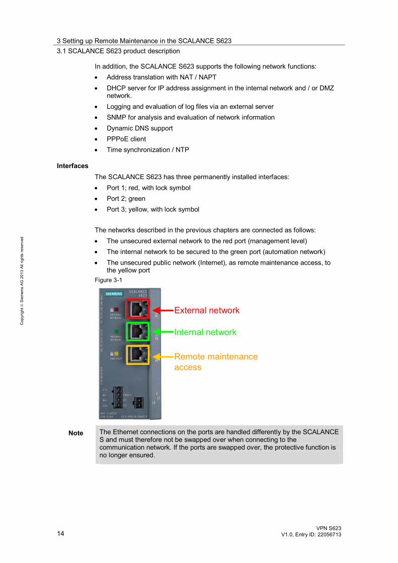
Interfaces The SCALANCE S623 has three permanently installed interfaces: Port 1; red, with lock symbol Port 2; green Port 3; yellow, with lock symbol
The networks described in the previous chapters are connected as follows: The unsecured external network to the red port (management level) The internal network to be secured to the green port (automation network) The unsecured public network (Internet), as remote maintenance access, to
the yellow port Figure 3-1
Internal network
External network
Remote maintenance access
Note The Ethernet connections on the ports are handled differently by the SCALANCE S and must therefore not be swapped over when connecting to the communication network. If the ports are swapped over, the protective function is no longer ensured.
3 Setting up Remote Maintenance in the SCALANCE S623 3.2 The remote maintenance application in the SCALANCE S623
VPN S623 V1.0, Entry ID: 22056713 15
Cop
yrig
ht
Sie
men
s A
G 2
013
All
right
s re
serv
ed
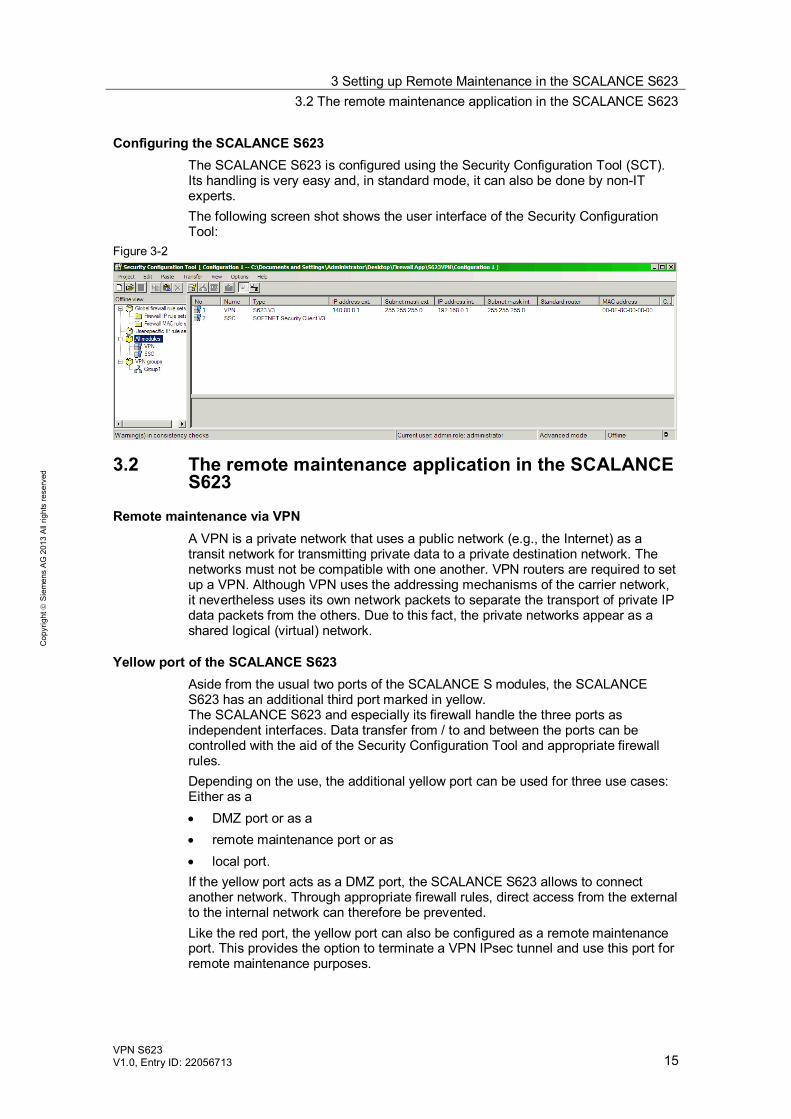
Configuring the SCALANCE S623 The SCALANCE S623 is configured using the Security Configuration Tool (SCT). Its handling is very easy and, in standard mode, it can also be done by non-IT experts. The following screen shot shows the user interface of the Security Configuration Tool:
Figure 3-2
3.2 The remote maintenance application in the SCALANCE S623
Remote maintenance via VPN A VPN is a private network that uses a public network (e.g., the Internet) as a transit network for transmitting private data to a private destination network. The networks must not be compatible with one another. VPN routers are required to set up a VPN. Although VPN uses the addressing mechanisms of the carrier network, it nevertheless uses its own network packets to separate the transport of private IP data packets from the others. Due to this fact, the private networks appear as a shared logical (virtual) network.
Yellow port of the SCALANCE S623 Aside from the usual two ports of the SCALANCE S modules, the SCALANCE S623 has an additional third port marked in yellow. The SCALANCE S623 and especially its firewall handle the three ports as independent interfaces. Data transfer from / to and between the ports can be controlled with the aid of the Security Configuration Tool and appropriate firewall rules. Depending on the use, the additional yellow port can be used for three use cases: Either as a DMZ port or as a remote maintenance port or as local port.
If the yellow port acts as a DMZ port, the SCALANCE S623 allows to connect another network. Through appropriate firewall rules, direct access from the external to the internal network can therefore be prevented. Like the red port, the yellow port can also be configured as a remote maintenance port. This provides the option to terminate a VPN IPsec tunnel and use this port for remote maintenance purposes.
3 Setting up Remote Maintenance in the SCALANCE S623 3.2 The remote maintenance application in the SCALANCE S623
16 VPN S623
V1.0, Entry ID: 22056713
Cop
yrig
ht
Sie
men
s A
G 2
013
All
right
s re
serv
ed
Furthermore, the yellow port can be used as a local port. For example, this is useful when the SCALANCE S623 is installed in a control cabinet and only the yellow port is to be made externally accessible for controlled service technician access to the networks. Due to the fact that both the DMZ function and the remote maintenance function expect the connection of a separate subnet, the yellow port is intended only for routing mode.
Note This application example covers only the VPN function of the yellow port. For more information on the different application options, please refer to the security manual in /1/ or the document “Setting up a Demilitarized Zone (DMZ) with the Aid of the SCALANCE S623” in /7/ in Chapter 8 (References).
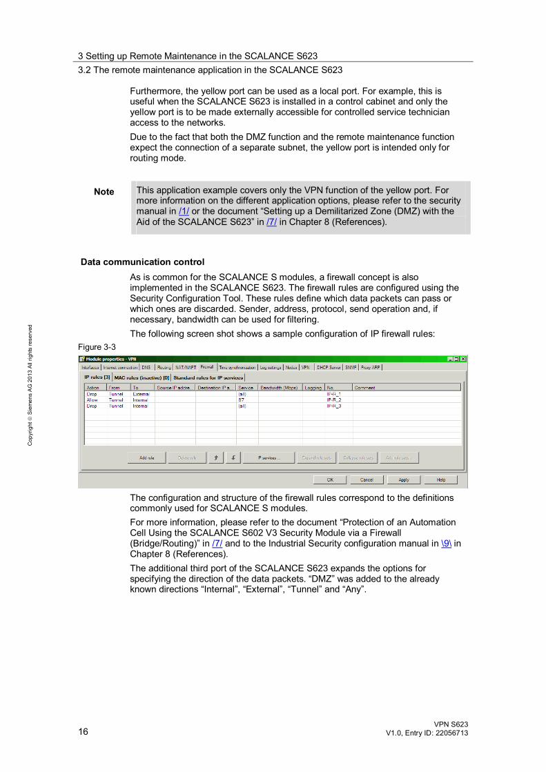
Data communication control As is common for the SCALANCE S modules, a firewall concept is also implemented in the SCALANCE S623. The firewall rules are configured using the Security Configuration Tool. These rules define which data packets can pass or which ones are discarded. Sender, address, protocol, send operation and, if necessary, bandwidth can be used for filtering. The following screen shot shows a sample configuration of IP firewall rules:
Figure 3-3
The configuration and structure of the firewall rules correspond to the definitions commonly used for SCALANCE S modules. For more information, please refer to the document “Protection of an Automation Cell Using the SCALANCE S602 V3 Security Module via a Firewall (Bridge/Routing)” in /7/ and to the Industrial Security configuration manual in \9\ in Chapter 8 (References). The additional third port of the SCALANCE S623 expands the options for specifying the direction of the data packets. “DMZ” was added to the already known directions “Internal”, “External”, “Tunnel” and “Any”.
3 Setting up Remote Maintenance in the SCALANCE S623 3.2 The remote maintenance application in the SCALANCE S623
VPN S623 V1.0, Entry ID: 22056713 17
Cop
yrig
ht
Sie
men
s A
G 2
013
All
right
s re
serv
ed
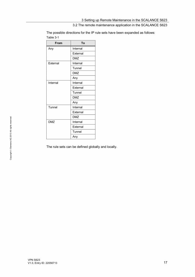
The possible directions for the IP rule sets have been expanded as follows: Table 3-1
From To
Any Internal External DMZ
External Internal Tunnel DMZ Any
Internal Internal External Tunnel DMZ Any
Tunnel Internal External DMZ
DMZ Internal External Tunnel Any
The rule sets can be defined globally and locally.
4 Function Mechanisms of the Scenarios 4.1 Functionality of the FTP scenario
18 VPN S623
V1.0, Entry ID: 22056713
Cop
yrig
ht
Sie
men
s A
G 2
013
All
right
s re
serv
ed
4 Function Mechanisms of the Scenarios 4.1 Functionality of the FTP scenario
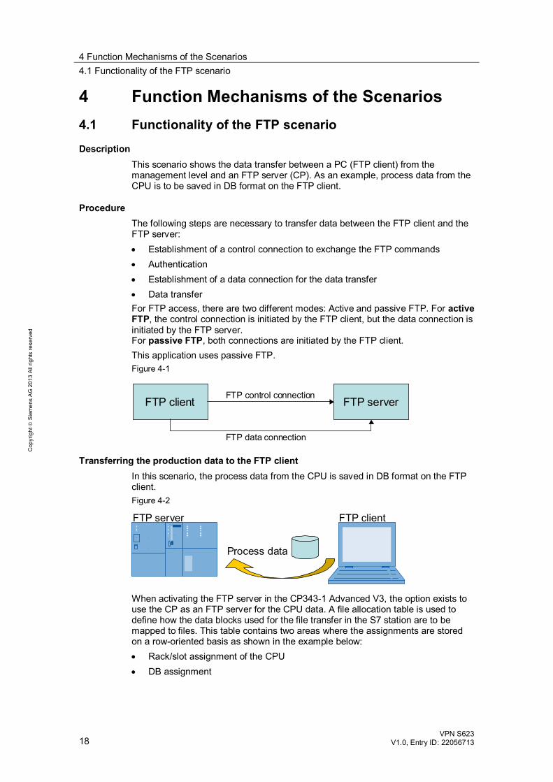
Description This scenario shows the data transfer between a PC (FTP client) from the management level and an FTP server (CP). As an example, process data from the CPU is to be saved in DB format on the FTP client.
Procedure The following steps are necessary to transfer data between the FTP client and the FTP server: Establishment of a control connection to exchange the FTP commands Authentication Establishment of a data connection for the data transfer Data transfer
For FTP access, there are two different modes: Active and passive FTP. For active FTP, the control connection is initiated by the FTP client, but the data connection is initiated by the FTP server. For passive FTP, both connections are initiated by the FTP client. This application uses passive FTP. Figure 4-1
FTP client FTP serverFTP control connection
FTP data connection
Transferring the production data to the FTP client In this scenario, the process data from the CPU is saved in DB format on the FTP client. Figure 4-2
FTP server FTP client
Process data
When activating the FTP server in the CP343-1 Advanced V3, the option exists to use the CP as an FTP server for the CPU data. A file allocation table is used to define how the data blocks used for the file transfer in the S7 station are to be mapped to files. This table contains two areas where the assignments are stored on a row-oriented basis as shown in the example below: Rack/slot assignment of the CPU DB assignment
4 Function Mechanisms of the Scenarios 4.1 Functionality of the FTP scenario
VPN S623 V1.0, Entry ID: 22056713 19
Cop
yrig
ht
Sie
men
s A
G 2
013
All
right
s re
serv
ed
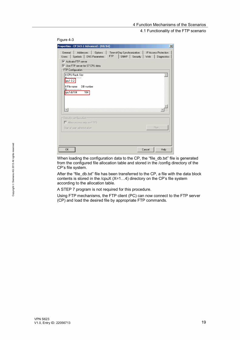
Figure 4-3
When loading the configuration data to the CP, the “file_db.txt” file is generated from the configured file allocation table and stored in the /config directory of the CP’s file system. After the “file_db.txt” file has been transferred to the CP, a file with the data block contents is stored in the /cpuX (X=1…4) directory on the CP’s file system according to the allocation table. A STEP 7 program is not required for this procedure. Using FTP mechanisms, the FTP client (PC) can now connect to the FTP server (CP) and load the desired file by appropriate FTP commands.
4 Function Mechanisms of the Scenarios 4.2 Functionality of the OPC scenario
20 VPN S623
V1.0, Entry ID: 22056713
Cop
yrig
ht
Sie
men
s A
G 2
013
All
right
s re
serv
ed
4.2 Functionality of the OPC scenario
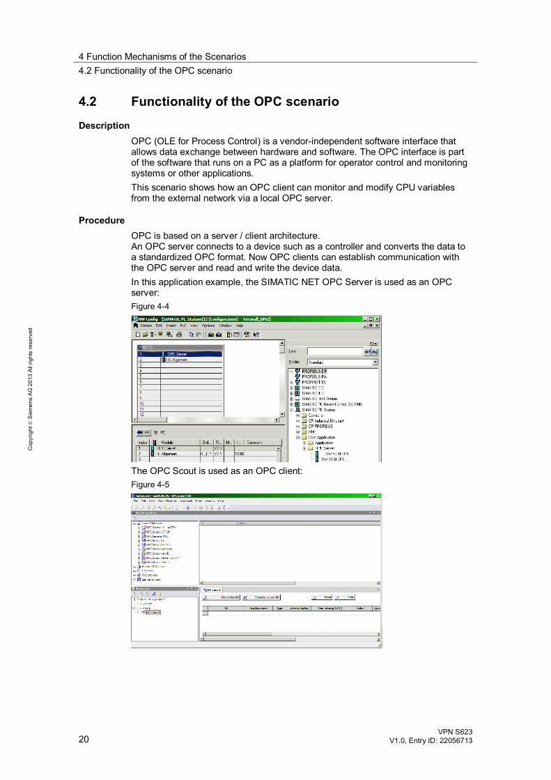
Description OPC (OLE for Process Control) is a vendor-independent software interface that allows data exchange between hardware and software. The OPC interface is part of the software that runs on a PC as a platform for operator control and monitoring systems or other applications. This scenario shows how an OPC client can monitor and modify CPU variables from the external network via a local OPC server.
Procedure OPC is based on a server / client architecture. An OPC server connects to a device such as a controller and converts the data to a standardized OPC format. Now OPC clients can establish communication with the OPC server and read and write the device data. In this application example, the SIMATIC NET OPC Server is used as an OPC server: Figure 4-4
The OPC Scout is used as an OPC client: Figure 4-5
5 Installation 5.1 Installing the hardware
VPN S623 V1.0, Entry ID: 22056713 21
Cop
yrig
ht
Sie
men
s A
G 2
013
All
right
s re
serv
ed
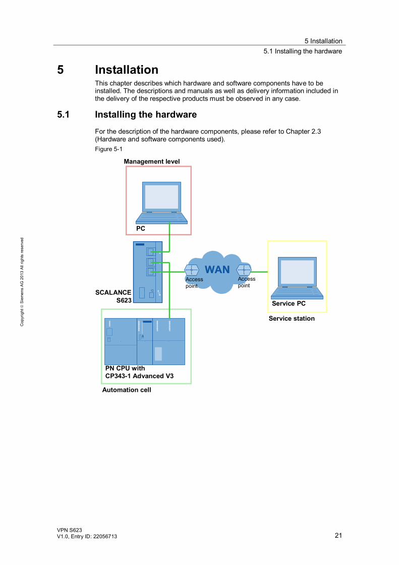
5 Installation This chapter describes which hardware and software components have to be installed. The descriptions and manuals as well as delivery information included in the delivery of the respective products must be observed in any case.
5.1 Installing the hardware For the description of the hardware components, please refer to Chapter 2.3 (Hardware and software components used). Figure 5-1
SCALANCE S623
PN CPU with CP343-1 Advanced V3
PC
Automation cell
Management level
Accesspoint
Service PC
Service station
Accesspoint
5 Installation 5.1 Installing the hardware
22 VPN S623
V1.0, Entry ID: 22056713
Cop
yrig
ht
Sie
men
s A
G 2
013
All
right
s re
serv
ed
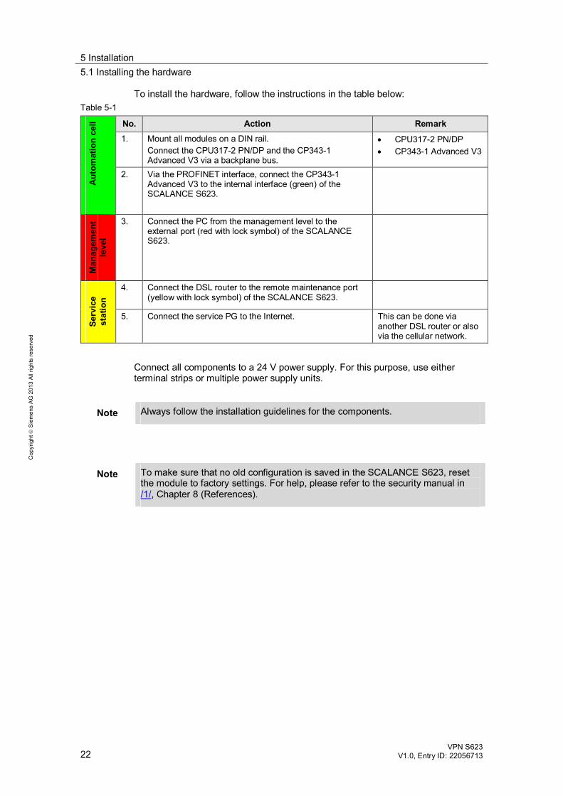
To install the hardware, follow the instructions in the table below: Table 5-1
Aut
omat
ion
cell No. Action Remark
1. Mount all modules on a DIN rail. Connect the CPU317-2 PN/DP and the CP343-1 Advanced V3 via a backplane bus.
CPU317-2 PN/DP CP343-1 Advanced V3
2. Via the PROFINET interface, connect the CP343-1 Advanced V3 to the internal interface (green) of the SCALANCE S623.
Man
agem
ent
leve
l
3. Connect the PC from the management level to the external port (red with lock symbol) of the SCALANCE S623.
Serv
ice
stat
ion
4. Connect the DSL router to the remote maintenance port (yellow with lock symbol) of the SCALANCE S623.
5. Connect the service PG to the Internet. This can be done via another DSL router or also via the cellular network.
Connect all components to a 24 V power supply. For this purpose, use either terminal strips or multiple power supply units.
Note Always follow the installation guidelines for the components.
Note To make sure that no old configuration is saved in the SCALANCE S623, reset the module to factory settings. For help, please refer to the security manual in /1/, Chapter 8 (References).
5 Installation 5.2 Installing the software
VPN S623 V1.0, Entry ID: 22056713 23
Cop
yrig
ht
Sie
men
s A
G 2
013
All
right
s re
serv
ed
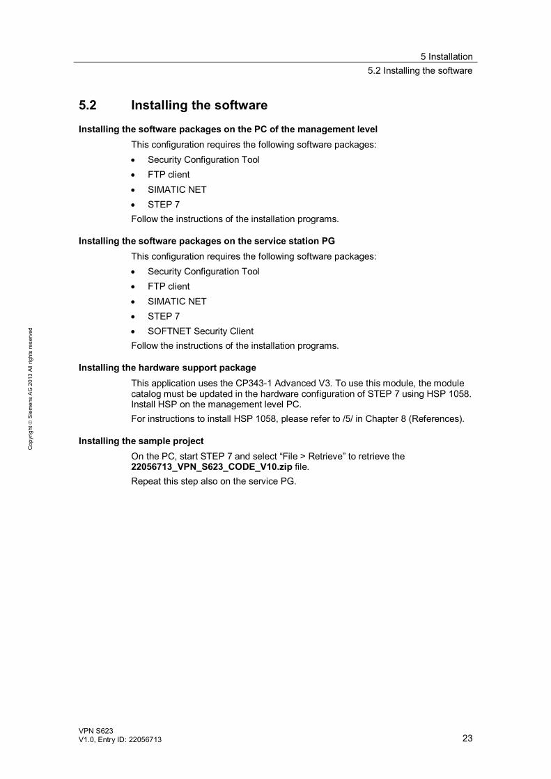
5.2 Installing the software
Installing the software packages on the PC of the management level This configuration requires the following software packages: Security Configuration Tool FTP client SIMATIC NET STEP 7
Follow the instructions of the installation programs.
Installing the software packages on the service station PG This configuration requires the following software packages: Security Configuration Tool FTP client SIMATIC NET STEP 7 SOFTNET Security Client
Follow the instructions of the installation programs.
Installing the hardware support package This application uses the CP343-1 Advanced V3. To use this module, the module catalog must be updated in the hardware configuration of STEP 7 using HSP 1058. Install HSP on the management level PC. For instructions to install HSP 1058, please refer to /5/ in Chapter 8 (References).
Installing the sample project On the PC, start STEP 7 and select “File > Retrieve” to retrieve the 22056713_VPN_S623_CODE_V10.zip file. Repeat this step also on the service PG.
6 Startup of the Application 6.1 Assigning the IP addresses
24 VPN S623
V1.0, Entry ID: 22056713
Cop
yrig
ht
Sie
men
s A
G 2
013
All
right
s re
serv
ed
6 Startup of the Application 6.1 Assigning the IP addresses
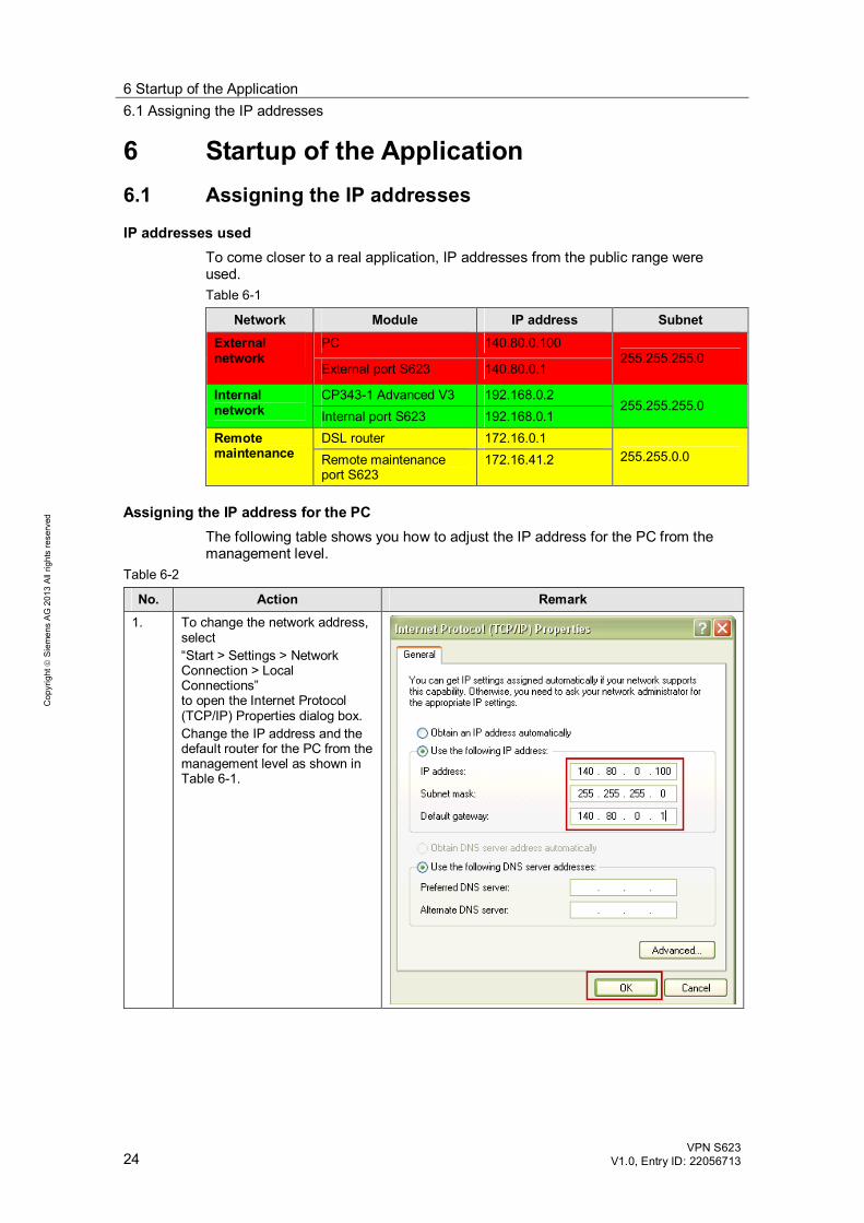
IP addresses used To come closer to a real application, IP addresses from the public range were used. Table 6-1
Network Module IP address Subnet External network
PC 140.80.0.100 255.255.255.0
External port S623 140.80.0.1
Internal network
CP343-1 Advanced V3 192.168.0.2 255.255.255.0
Internal port S623 192.168.0.1 Remote maintenance
DSL router 172.16.0.1 255.255.0.0 Remote maintenance
port S623 172.16.41.2
Assigning the IP address for the PC The following table shows you how to adjust the IP address for the PC from the management level.
Table 6-2
No. Action Remark 1. To change the network address,
select “Start > Settings > Network Connection > Local Connections” to open the Internet Protocol (TCP/IP) Properties dialog box. Change the IP address and the default router for the PC from the management level as shown in Table 6-1.
6 Startup of the Application 6.1 Assigning the IP addresses
VPN S623 V1.0, Entry ID: 22056713 25
Cop
yrig
ht
Sie
men
s A
G 2
013
All
right
s re
serv
ed
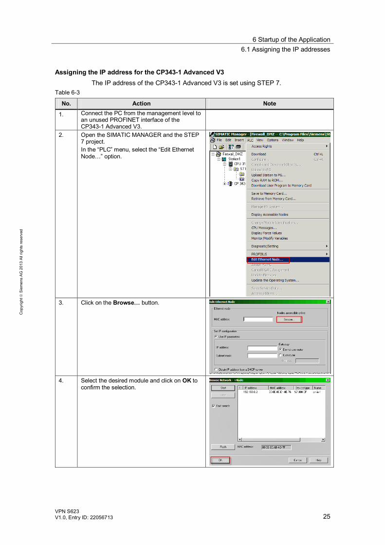
Assigning the IP address for the CP343-1 Advanced V3 The IP address of the CP343-1 Advanced V3 is set using STEP 7.
Table 6-3
No. Action Note
1. Connect the PC from the management level to an unused PROFINET interface of the CP343-1 Advanced V3.
2. Open the SIMATIC MANAGER and the STEP 7 project. In the “PLC” menu, select the “Edit Ethernet Node…” option.
3. Click on the Browse… button.
4. Select the desired module and click on OK to
confirm the selection.
6 Startup of the Application 6.1 Assigning the IP addresses
26 VPN S623
V1.0, Entry ID: 22056713
Cop
yrig
ht
Sie
men
s A
G 2
013
All
right
s re
serv
ed
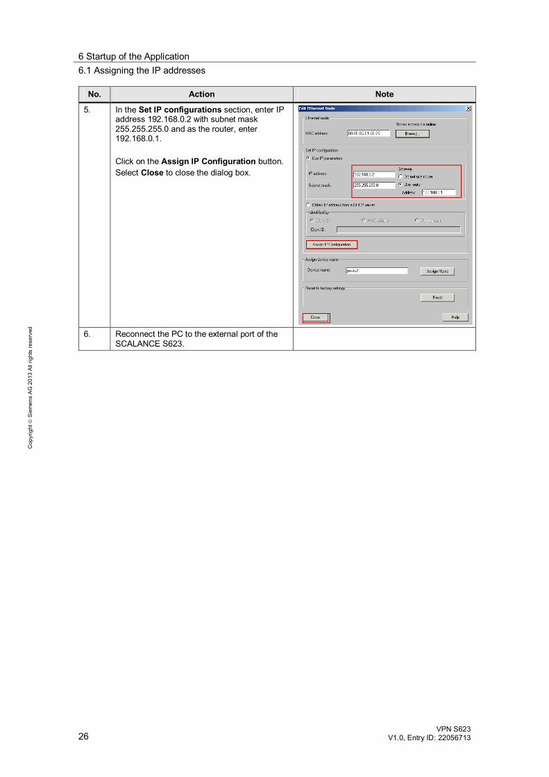
No. Action Note
5. In the Set IP configurations section, enter IP address 192.168.0.2 with subnet mask 255.255.255.0 and as the router, enter 192.168.0.1. Click on the Assign IP Configuration button. Select Close to close the dialog box.
6. Reconnect the PC to the external port of the
SCALANCE S623.
6 Startup of the Application 6.2 Configuring with the Security Configuration Tool
VPN S623 V1.0, Entry ID: 22056713 27
Cop
yrig
ht
Sie
men
s A
G 2
013
All
right
s re
serv
ed
6.2 Configuring with the Security Configuration Tool
6.2.1 Creating a project with the security modules
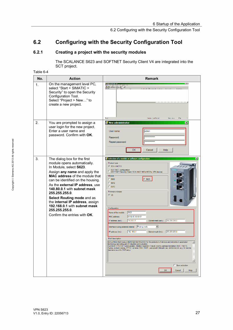
The SCALANCE S623 and SOFTNET Security Client V4 are integrated into the SCT project.
Table 6-4
No. Action Remark 1. On the management level PC,
select “Start > SIMATIC > Security” to open the Security Configuration Tool. Select “Project > New…” to create a new project.
2. You are prompted to assign a
user login for the new project. Enter a user name and password. Confirm with OK.
3. The dialog box for the first
module opens automatically. In Module, select S623. Assign any name and apply the MAC address of the module that can be identified on the housing. As the external IP address, use 140.80.0.1 with subnet mask 255.255.255.0. Select Routing mode and as the internal IP address, assign 192.168.0.1 with subnet mask 255.255.255.0. Confirm the entries with OK.
6 Startup of the Application 6.2 Configuring with the Security Configuration Tool
28 VPN S623
V1.0, Entry ID: 22056713
Cop
yrig
ht
Sie
men
s A
G 2
013
All
right
s re
serv
ed
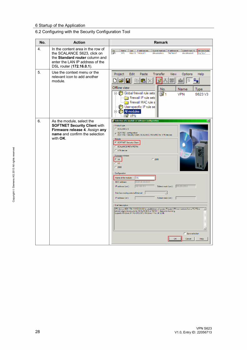
No. Action Remark 4. In the content area in the row of
the SCALANCE S623, click on the Standard router column and enter the LAN IP address of the DSL router (172.16.0.1).
5. Use the context menu or the relevant icon to add another module.
6. As the module, select the
SOFTNET Security Client with Firmware release 4. Assign any name and confirm the selection with OK.
6 Startup of the Application 6.2 Configuring with the Security Configuration Tool
VPN S623 V1.0, Entry ID: 22056713 29
Cop
yrig
ht
Sie
men
s A
G 2
013
All
right
s re
serv
ed
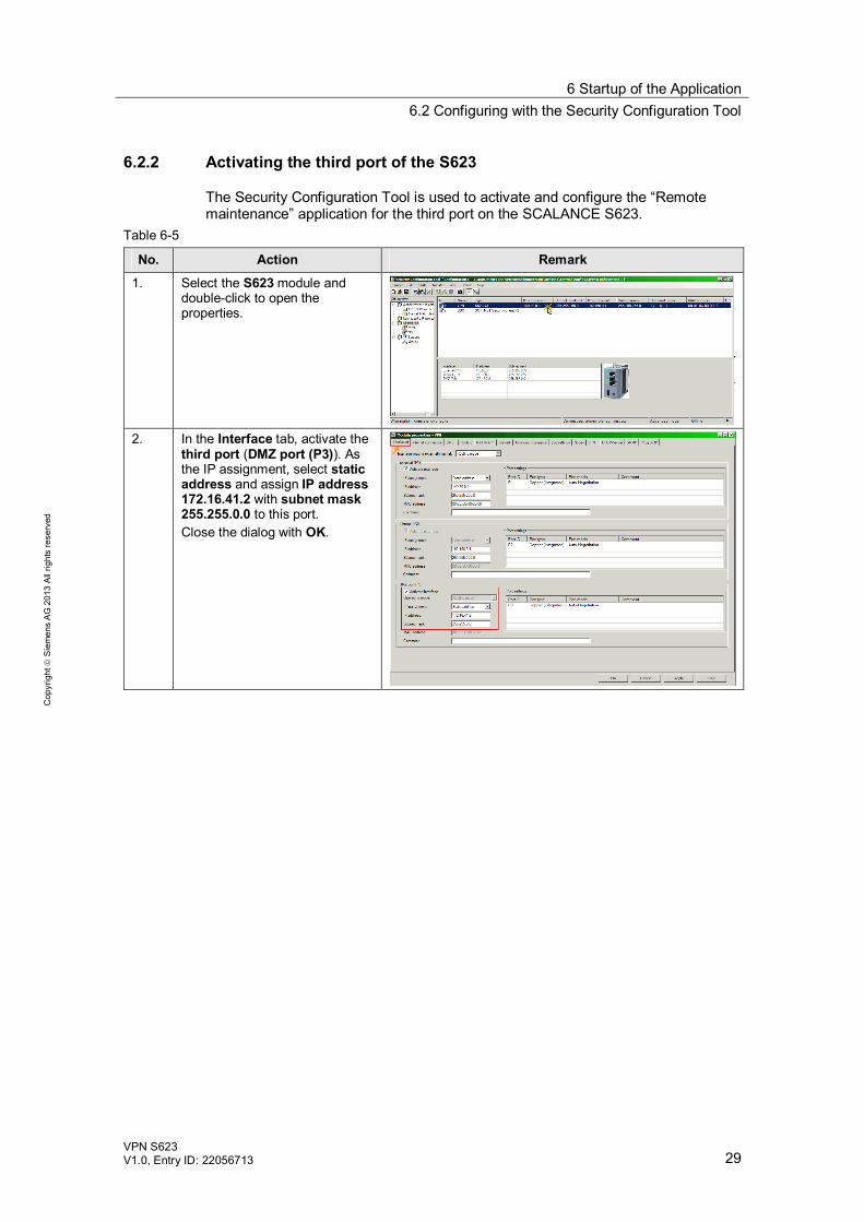
6.2.2 Activating the third port of the S623
The Security Configuration Tool is used to activate and configure the “Remote maintenance” application for the third port on the SCALANCE S623.
Table 6-5
No. Action Remark
1. Select the S623 module and double-click to open the properties.
2. In the Interface tab, activate the
third port (DMZ port (P3)). As the IP assignment, select static address and assign IP address 172.16.41.2 with subnet mask 255.255.0.0 to this port. Close the dialog with OK.
6 Startup of the Application 6.2 Configuring with the Security Configuration Tool
30 VPN S623
V1.0, Entry ID: 22056713
Cop
yrig
ht
Sie
men
s A
G 2
013
All
right
s re
serv
ed
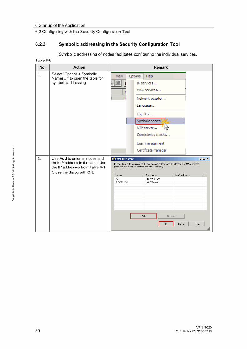
6.2.3 Symbolic addressing in the Security Configuration Tool
Symbolic addressing of nodes facilitates configuring the individual services. Table 6-6
No. Action Remark 1. Select “Options > Symbolic
Names…” to open the table for symbolic addressing.
2. Use Add to enter all nodes and
their IP address in the table. Use the IP addresses from Table 6-1. Close the dialog with OK.
6 Startup of the Application 6.2 Configuring with the Security Configuration Tool
VPN S623 V1.0, Entry ID: 22056713 31
Cop
yrig
ht
Sie
men
s A
G 2
013
All
right
s re
serv
ed
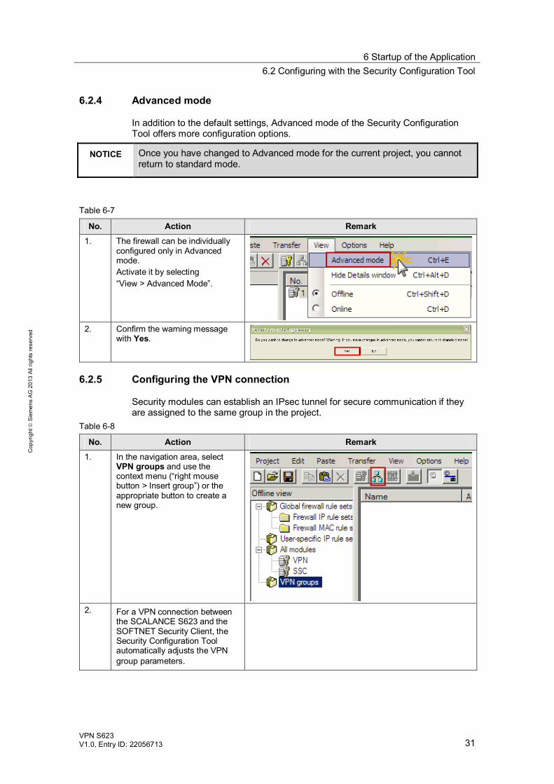
6.2.4 Advanced mode
In addition to the default settings, Advanced mode of the Security Configuration Tool offers more configuration options.
NOTICE Once you have changed to Advanced mode for the current project, you cannot return to standard mode.
Table 6-7
No. Action Remark 1. The firewall can be individually
configured only in Advanced mode. Activate it by selecting “View > Advanced Mode”.
2. Confirm the warning message
with Yes.
6.2.5 Configuring the VPN connection
Security modules can establish an IPsec tunnel for secure communication if they are assigned to the same group in the project.
Table 6-8
No. Action Remark 1. In the navigation area, select
VPN groups and use the context menu (“right mouse button > Insert group”) or the appropriate button to create a new group.
2. For a VPN connection between
the SCALANCE S623 and the SOFTNET Security Client, the Security Configuration Tool automatically adjusts the VPN group parameters.
6 Startup of the Application 6.2 Configuring with the Security Configuration Tool
32 VPN S623
V1.0, Entry ID: 22056713
Cop
yrig
ht
Sie
men
s A
G 2
013
All
right
s re
serv
ed
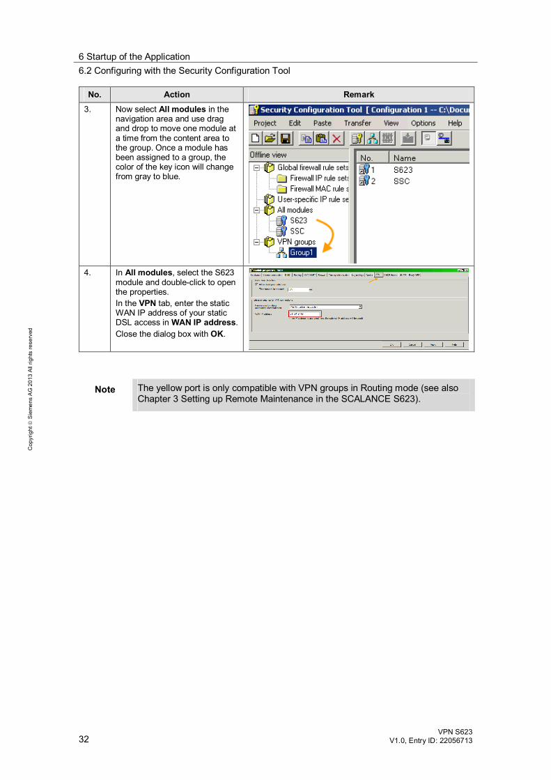
No. Action Remark 3. Now select All modules in the
navigation area and use drag and drop to move one module at a time from the content area to the group. Once a module has been assigned to a group, the color of the key icon will change from gray to blue.
4. In All modules, select the S623
module and double-click to open the properties. In the VPN tab, enter the static WAN IP address of your static DSL access in WAN IP address. Close the dialog box with OK.
Note The yellow port is only compatible with VPN groups in Routing mode (see also Chapter 3 Setting up Remote Maintenance in the SCALANCE S623).
6 Startup of the Application 6.2 Configuring with the Security Configuration Tool
VPN S623 V1.0, Entry ID: 22056713 33
Cop
yrig
ht
Sie
men
s A
G 2
013
All
right
s re
serv
ed
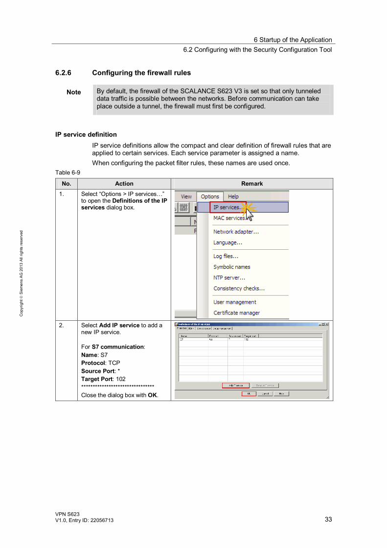
6.2.6 Configuring the firewall rules
Note By default, the firewall of the SCALANCE S623 V3 is set so that only tunneled data traffic is possible between the networks. Before communication can take place outside a tunnel, the firewall must first be configured.
IP service definition IP service definitions allow the compact and clear definition of firewall rules that are applied to certain services. Each service parameter is assigned a name. When configuring the packet filter rules, these names are used once.
Table 6-9
No. Action Remark 1. Select “Options > IP services…”
to open the Definitions of the IP services dialog box.
2. Select Add IP service to add a
new IP service. For S7 communication: Name: S7 Protocol: TCP Source Port: * Target Port: 102 ******************************** Close the dialog box with OK.
6 Startup of the Application 6.2 Configuring with the Security Configuration Tool
34 VPN S623
V1.0, Entry ID: 22056713
Cop
yrig
ht
Sie
men
s A
G 2
013
All
right
s re
serv
ed
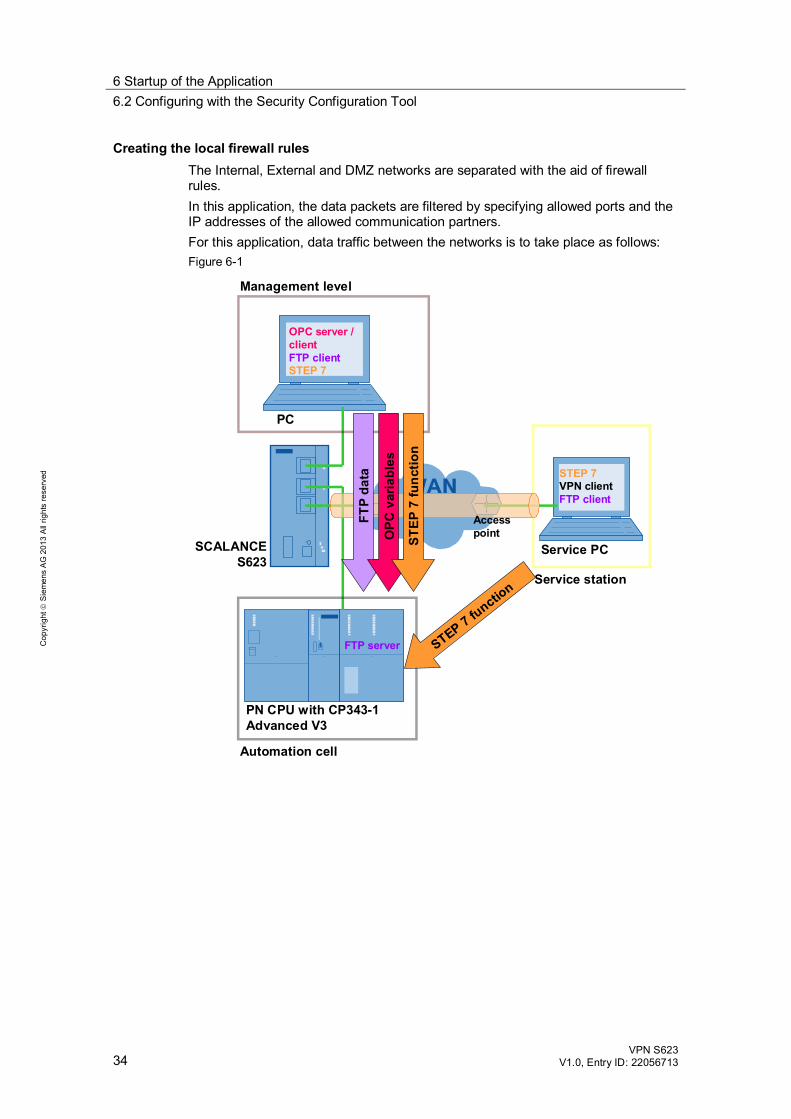
Creating the local firewall rules The Internal, External and DMZ networks are separated with the aid of firewall rules. In this application, the data packets are filtered by specifying allowed ports and the IP addresses of the allowed communication partners. For this application, data traffic between the networks is to take place as follows: Figure 6-1
SCALANCE S623
PN CPU with CP343-1 Advanced V3
Service PC
PC
Automation cell
Management level
Service station
OPC server / clientFTP clientSTEP 7
STEP 7VPN clientFTP client
FTP server STEP 7 functio
n
FTP
data
OPC
var
iabl
es
STEP
7 fu
nctio
n
Accesspoint
6 Startup of the Application 6.2 Configuring with the Security Configuration Tool
VPN S623 V1.0, Entry ID: 22056713 35
Cop
yrig
ht
Sie
men
s A
G 2
013
All
right
s re
serv
ed
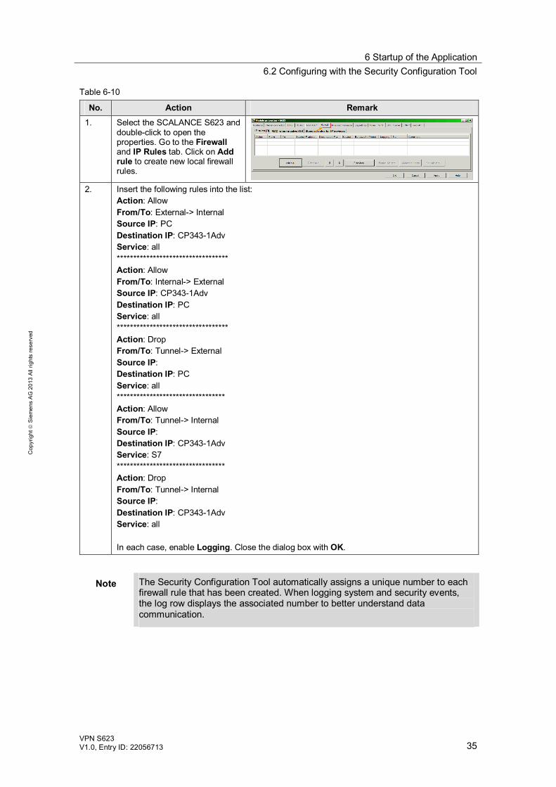
Table 6-10
No. Action Remark 1. Select the SCALANCE S623 and
double-click to open the properties. Go to the Firewall and IP Rules tab. Click on Add rule to create new local firewall rules.
2. Insert the following rules into the list:
Action: Allow From/To: External-> Internal Source IP: PC Destination IP: CP343-1Adv Service: all ********************************** Action: Allow From/To: Internal-> External Source IP: CP343-1Adv Destination IP: PC Service: all ********************************** Action: Drop From/To: Tunnel-> External Source IP: Destination IP: PC Service: all ********************************* Action: Allow From/To: Tunnel-> Internal Source IP: Destination IP: CP343-1Adv Service: S7 ********************************* Action: Drop From/To: Tunnel-> Internal Source IP: Destination IP: CP343-1Adv Service: all In each case, enable Logging. Close the dialog box with OK.
Note The Security Configuration Tool automatically assigns a unique number to each firewall rule that has been created. When logging system and security events, the log row displays the associated number to better understand data communication.
6 Startup of the Application 6.2 Configuring with the Security Configuration Tool
36 VPN S623
V1.0, Entry ID: 22056713
Cop
yrig
ht
Sie
men
s A
G 2
013
All
right
s re
serv
ed
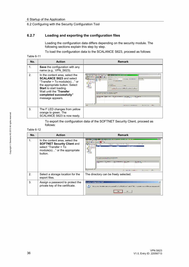
6.2.7 Loading and exporting the configuration files
Loading the configuration data differs depending on the security module. The following sections explain this step by step. To load the configuration data to the SCALANCE S623, proceed as follows:
Table 6-11
No. Action Remark
1. Save the configuration with any name (e.g., VPN_S623).
2. In the content area, select the SCALANCE S623 and select “Transfer > To module(s)…” or the appropriate button. Select Start to start loading. Wait until the “Transfer completed successfully” message appears.
3. The F LED changes from yellow
orange to green. The SCALANCE S623 is now ready.
To export the configuration data of the SOFTNET Security Client, proceed as follows:
Table 6-12
No. Action Remark
1. In the content area, select the SOFTNET Security Client and select “Transfer > To module(s)…” or the appropriate button.
2. Select a storage location for the
export files. The directory can be freely selected.
3. Assign a password to protect the private key of the certificate.
6 Startup of the Application 6.3 Configuring the DSL router
VPN S623 V1.0, Entry ID: 22056713 37
Cop
yrig
ht
Sie
men
s A
G 2
013
All
right
s re
serv
ed
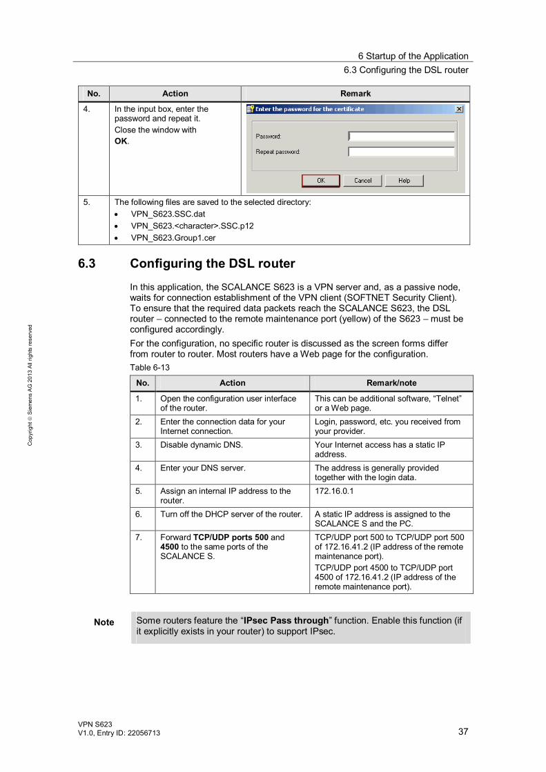
No. Action Remark
4. In the input box, enter the password and repeat it. Close the window with OK.
5. The following files are saved to the selected directory:
VPN_S623.SSC.dat VPN_S623.<character>.SSC.p12 VPN_S623.Group1.cer
6.3 Configuring the DSL router
In this application, the SCALANCE S623 is a VPN server and, as a passive node, waits for connection establishment of the VPN client (SOFTNET Security Client). To ensure that the required data packets reach the SCALANCE S623, the DSL router – connected to the remote maintenance port (yellow) of the S623 – must be configured accordingly. For the configuration, no specific router is discussed as the screen forms differ from router to router. Most routers have a Web page for the configuration. Table 6-13
No. Action Remark/note
1. Open the configuration user interface of the router.
This can be additional software, “Telnet” or a Web page.
2. Enter the connection data for your Internet connection.
Login, password, etc. you received from your provider.
3. Disable dynamic DNS. Your Internet access has a static IP address.
4. Enter your DNS server. The address is generally provided together with the login data.
5. Assign an internal IP address to the router.
172.16.0.1
6. Turn off the DHCP server of the router. A static IP address is assigned to the SCALANCE S and the PC.
7. Forward TCP/UDP ports 500 and 4500 to the same ports of the SCALANCE S.
TCP/UDP port 500 to TCP/UDP port 500 of 172.16.41.2 (IP address of the remote maintenance port). TCP/UDP port 4500 to TCP/UDP port 4500 of 172.16.41.2 (IP address of the remote maintenance port).
Note Some routers feature the “IPsec Pass through” function. Enable this function (if it explicitly exists in your router) to support IPsec.
6 Startup of the Application 6.4 Configuring the FTP scenario
38 VPN S623
V1.0, Entry ID: 22056713
Cop
yrig
ht
Sie
men
s A
G 2
013
All
right
s re
serv
ed
6.4 Configuring the FTP scenario
To operate the FTP scenario, the following components are necessary: In the internal network: CP343-1 Advanced V3 as an FTP server At the management level: FTP client software tool
Setting for the FTP clients (software-based) This section does not provide step-by-step instructions as the configuration screen forms differ for the numerous FTP software tools available on the market. The following section lists the settings you have to make in your FTP client to access the FTP servers: The IP address of the FTP server is 192.168.0.2 (IP address of the CP343-1
Advanced V3 in the internal network). Passive mode is always used for the transfer setting. In this application, the login for the FTP servers is defined as follows:
– User name: ftp_user – Password: ftp_user
Settings for the FTP server (CP343-1 Advanced V3) All the information required for using FTP such as the login data for the FTP client is stored in the hardware configuration of the CP343-1 Advanced V3 in STEP 7.
Note If you want to use different data to log in to the FTP server, you can also change the login data.

6 Startup of the Application 6.5 Configuring the OPC scenario
VPN S623 V1.0, Entry ID: 22056713 39
Cop
yrig
ht
Sie
men
s A
G 2
013
All
right
s re
serv
ed
6.5 Configuring the OPC scenario
Parameterizing the PC station The OPC server is required for the “Production monitoring” scenario. In the supplied STEP 7 project, the PC station with the OPC server has already been configured accordingly. This configuration data is now loaded to the PC from the management level.
Table 6-14
No. Action Remark
1. On the PC, select “Start > Component Configurator” or the appropriate icon in the notification area of the Windows taskbar to open the Station Configuration Editor. Use the Import Station… button to load the configuration data of the PC station from STEP 7.
2. Navigate to the installation
directory of the supplied STEP 7 project. In the XDBs folder, you will find the pcst_1.xdb file. Select this file and use the appropriate button to open it.
6 Startup of the Application 6.5 Configuring the OPC scenario
40 VPN S623
V1.0, Entry ID: 22056713
Cop
yrig
ht
Sie
men
s A
G 2
013
All
right
s re
serv
ed
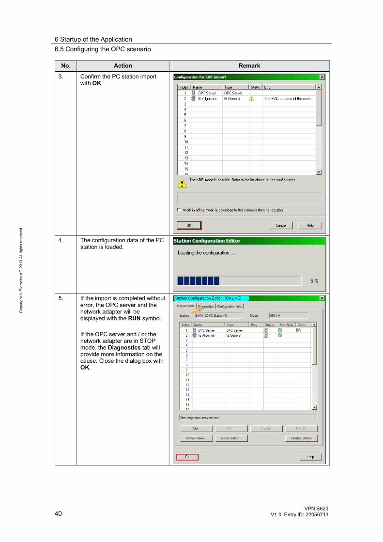
No. Action Remark
3. Confirm the PC station import with OK.
4. The configuration data of the PC
station is loaded.
5. If the import is completed without
error, the OPC server and the network adapter will be displayed with the RUN symbol. If the OPC server and / or the network adapter are in STOP mode, the Diagnostics tab will provide more information on the cause. Close the dialog box with OK.
6 Startup of the Application 6.6 Activating the VPN tunnel with the SOFTNET Security Client
VPN S623 V1.0, Entry ID: 22056713 41
Cop
yrig
ht
Sie
men
s A
G 2
013
All
right
s re
serv
ed
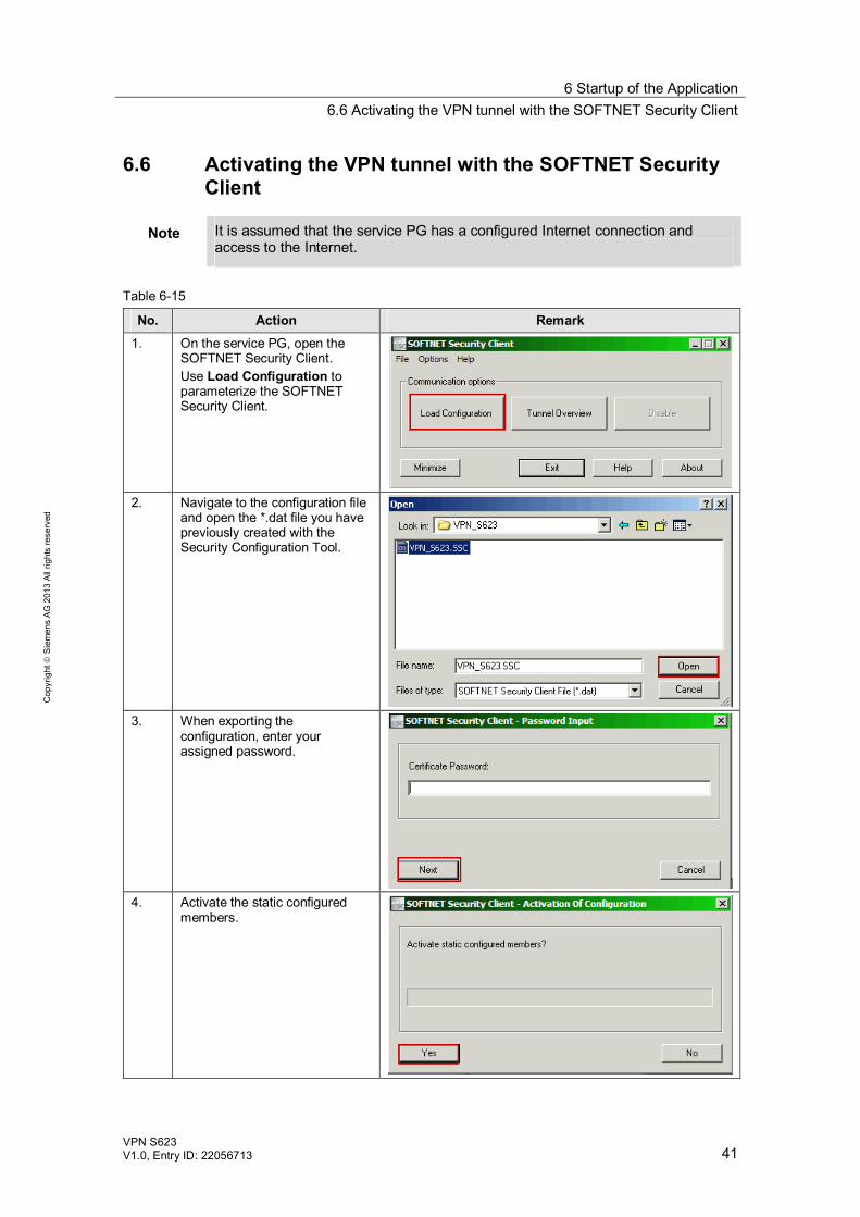
6.6 Activating the VPN tunnel with the SOFTNET Security Client
Note It is assumed that the service PG has a configured Internet connection and access to the Internet.
Table 6-15
No. Action Remark 1. On the service PG, open the
SOFTNET Security Client. Use Load Configuration to parameterize the SOFTNET Security Client.
2. Navigate to the configuration file
and open the *.dat file you have previously created with the Security Configuration Tool.
3. When exporting the
configuration, enter your assigned password.
4. Activate the static configured
members.
6 Startup of the Application 6.7 Loading the controller
42 VPN S623
V1.0, Entry ID: 22056713
Cop
yrig
ht
Sie
men
s A
G 2
013
All
right
s re
serv
ed
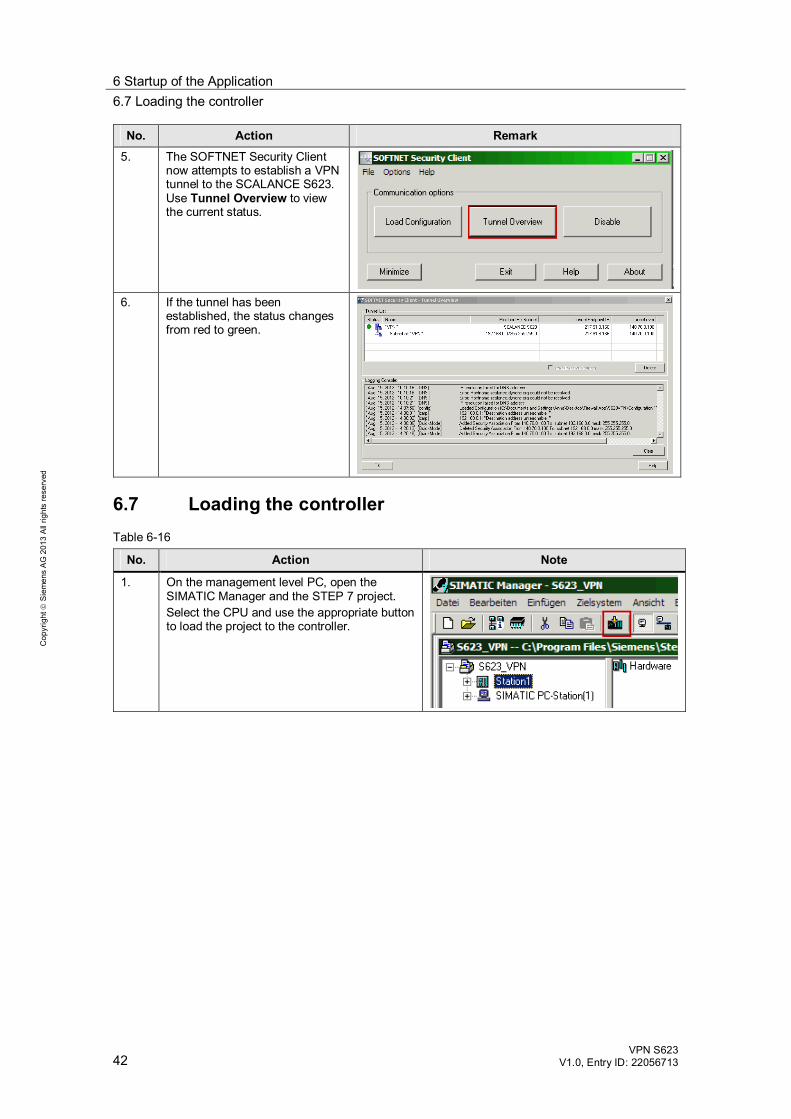
No. Action Remark 5. The SOFTNET Security Client
now attempts to establish a VPN tunnel to the SCALANCE S623. Use Tunnel Overview to view the current status.
6. If the tunnel has been
established, the status changes from red to green.
6.7 Loading the controller Table 6-16
No. Action Note
1. On the management level PC, open the SIMATIC Manager and the STEP 7 project. Select the CPU and use the appropriate button to load the project to the controller.
7 Operation of the Application 7.1 Overview
VPN S623 V1.0, Entry ID: 22056713 43
Cop
yrig
ht
Sie
men
s A
G 2
013
All
right
s re
serv
ed
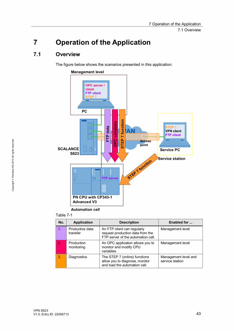
7 Operation of the Application 7.1 Overview
The figure below shows the scenarios presented in this application:
SCALANCE S623
PN CPU with CP343-1 Advanced V3
Service PC
PC
Automation cell
Management level
Service station
OPC server / clientFTP clientSTEP 7
STEP 7VPN clientFTP client
FTP server STEP 7 functio
n
FTP
data
OPC
var
iabl
es
STEP
7 fu
nctio
n
Accesspoint
Table 7-1
No. Application Description Enabled for ...
1. Productive data transfer
An FTP client can regularly request production data from the FTP server of the automation cell.
Management level
2. Production monitoring
An OPC application allows you to monitor and modify CPU variables.
Management level
3. Diagnostics The STEP 7 (online) functions allow you to diagnose, monitor and load the automation cell.
Management level and service station
7 Operation of the Application 7.2 Demonstration of the scenarios
44 VPN S623
V1.0, Entry ID: 22056713
Cop
yrig
ht
Sie
men
s A
G 2
013
All
right
s re
serv
ed
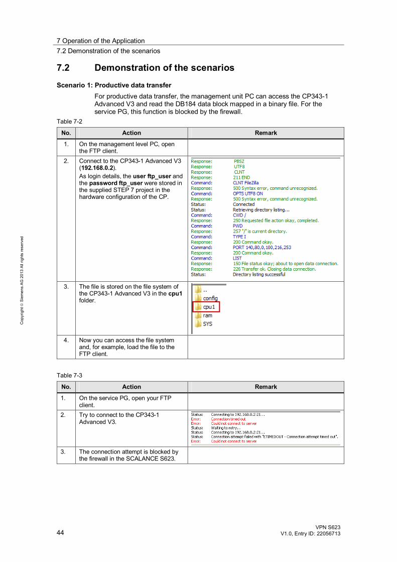
7.2 Demonstration of the scenarios
Scenario 1: Productive data transfer For productive data transfer, the management unit PC can access the CP343-1 Advanced V3 and read the DB184 data block mapped in a binary file. For the service PG, this function is blocked by the firewall.
Table 7-2
No. Action Remark
1. On the management level PC, open the FTP client.
2. Connect to the CP343-1 Advanced V3 (192.168.0.2). As login details, the user ftp_user and the password ftp_user were stored in the supplied STEP 7 project in the hardware configuration of the CP.
3. The file is stored on the file system of
the CP343-1 Advanced V3 in the cpu1 folder.
4. Now you can access the file system
and, for example, load the file to the FTP client.
Table 7-3
No. Action Remark
1. On the service PG, open your FTP client.
2. Try to connect to the CP343-1 Advanced V3.
3. The connection attempt is blocked by
the firewall in the SCALANCE S623.
7 Operation of the Application 7.2 Demonstration of the scenarios
VPN S623 V1.0, Entry ID: 22056713 45
Cop
yrig
ht
Sie
men
s A
G 2
013
All
right
s re
serv
ed
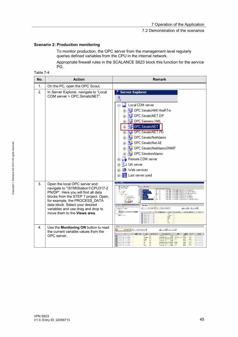
Scenario 2: Production monitoring To monitor production, the OPC server from the management level regularly queries defined variables from the CPU in the internal network. Appropriate firewall rules in the SCALANCE S623 block this function for the service PG.
Table 7-4
No. Action Remark
1. On the PC, open the OPC Scout. 2. In Server Explorer, navigate to “Local
COM server > OPC.SimaticNET”.
3. Open the local OPC server and
navigate to “\SYM\Station1\CPU317-2 PN/DP”. Here you will find all data blocks from the STEP 7 project. Open, for example, the PROCESS_DATA data block. Select your desired variables and use drag and drop to move them to the Views area.
4. Use the Monitoring ON button to read
the current variable values from the OPC server.
7 Operation of the Application 7.2 Demonstration of the scenarios
46 VPN S623
V1.0, Entry ID: 22056713
Cop
yrig
ht
Sie
men
s A
G 2
013
All
right
s re
serv
ed
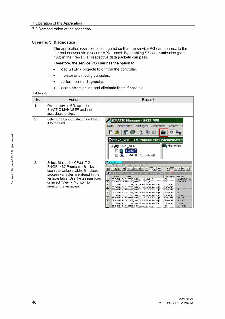
Scenario 3: Diagnostics The application example is configured so that the service PG can connect to the internal network via a secure VPN tunnel. By enabling S7 communication (port 102) in the firewall, all respective data packets can pass. Therefore, the service PG user has the option to load STEP 7 projects to or from the controller. monitor and modify variables. perform online diagnostics. locate errors online and eliminate them if possible.
Table 7-5
No. Action Remark 1. On the service PG, open the
SIMATIC MANAGER and the associated project.
2. Select the S7-300 station and load it to the CPU.
3. Select Station1 > CPU317-2
PN/DP > S7 Program > Blocks to open the variable table. Simulated process variables are stored in the variable table. Use the glasses icon or select “View > Monitor” to monitor the variables.
7 Operation of the Application 7.2 Demonstration of the scenarios
VPN S623 V1.0, Entry ID: 22056713 47
Cop
yrig
ht
Sie
men
s A
G 2
013
All
right
s re
serv
ed
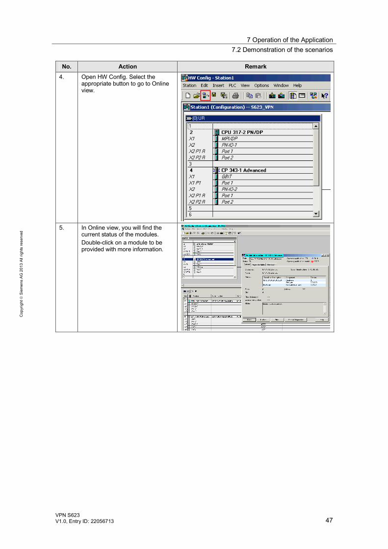
No. Action Remark 4. Open HW Config. Select the
appropriate button to go to Online view.
5. In Online view, you will find the
current status of the modules. Double-click on a module to be provided with more information.
8 References
48 VPN S623
V1.0, Entry ID: 22056713
Cop
yrig
ht
Sie
men
s A
G 2
013
All
right
s re
serv
ed
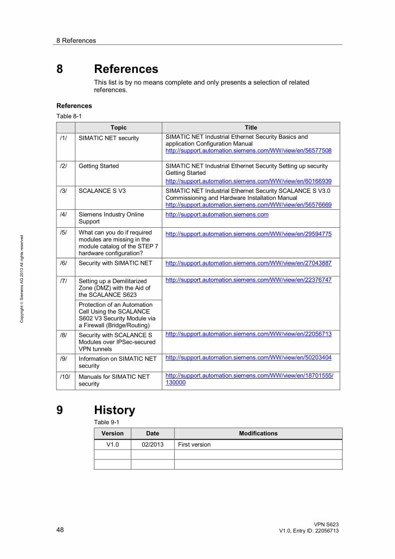
8 References This list is by no means complete and only presents a selection of related references.
References Table 8-1
Topic Title /1/ SIMATIC NET security SIMATIC NET Industrial Ethernet Security Basics and
application Configuration Manual http://support.automation.siemens.com/WW/view/en/56577508
/2/ Getting Started SIMATIC NET Industrial Ethernet Security Setting up security Getting Started http://support.automation.siemens.com/WW/view/en/60166939
/3/ SCALANCE S V3 SIMATIC NET Industrial Ethernet Security SCALANCE S V3.0 Commissioning and Hardware Installation Manual http://support.automation.siemens.com/WW/view/en/56576669
/4/ Siemens Industry Online Support
http://support.automation.siemens.com
/5/ What can you do if required modules are missing in the module catalog of the STEP 7 hardware configuration?
http://support.automation.siemens.com/WW/view/en/29594775
/6/ Security with SIMATIC NET http://support.automation.siemens.com/WW/view/en/27043887
/7/ Setting up a Demilitarized Zone (DMZ) with the Aid of the SCALANCE S623
http://support.automation.siemens.com/WW/view/en/22376747
Protection of an Automation Cell Using the SCALANCE S602 V3 Security Module via a Firewall (Bridge/Routing)
/8/ Security with SCALANCE S Modules over IPSec-secured VPN tunnels
http://support.automation.siemens.com/WW/view/en/22056713
/9/ Information on SIMATIC NET security
http://support.automation.siemens.com/WW/view/en/50203404
/10/ Manuals for SIMATIC NET security
http://support.automation.siemens.com/WW/view/en/18701555/130000
9 History Table 9-1
Version Date Modifications
V1.0 02/2013 First version