Embed Size (px)
Citation preview
Universitat Karlsruhe (TH)Fakultat fur InformatikSystem Architecture Group
Fabian Knittel
Study Thesis
Scalable Source Routingin the AmbiCompEnvironment
Tutors: Johannes Eickhold, Pengfei Diand Bjorn Saballus
Registration date: October 30, 2008Submission date: April 30, 2009


Contents
1 Introduction 3
2 The AmbiComp platform 52.1 Hardware . . . . . . . . . . . . . . . . . . . . . . . . . . . . . . . . 52.2 Software . . . . . . . . . . . . . . . . . . . . . . . . . . . . . . . . . 62.3 Build environment . . . . . . . . . . . . . . . . . . . . . . . . . . . 72.4 Integration of the SSR protocol . . . . . . . . . . . . . . . . . . . . . 7
2.4.1 Interaction . . . . . . . . . . . . . . . . . . . . . . . . . . . 72.4.2 Environment . . . . . . . . . . . . . . . . . . . . . . . . . . 9
3 Introduction to ssr-core 113.1 Important components . . . . . . . . . . . . . . . . . . . . . . . . . 11
3.1.1 The node . . . . . . . . . . . . . . . . . . . . . . . . . . . . 113.1.2 Routing . . . . . . . . . . . . . . . . . . . . . . . . . . . . . 113.1.3 Timers . . . . . . . . . . . . . . . . . . . . . . . . . . . . . 133.1.4 Messages . . . . . . . . . . . . . . . . . . . . . . . . . . . . 14
3.2 State machine . . . . . . . . . . . . . . . . . . . . . . . . . . . . . . 14
4 Changes to ssr-core 174.1 Avoiding heap memory and the STL . . . . . . . . . . . . . . . . . . 17
4.1.1 SSR messages . . . . . . . . . . . . . . . . . . . . . . . . . 184.1.2 SSR payload messages . . . . . . . . . . . . . . . . . . . . . 184.1.3 SSR timer events . . . . . . . . . . . . . . . . . . . . . . . . 194.1.4 NIC addresses . . . . . . . . . . . . . . . . . . . . . . . . . 204.1.5 Interface table . . . . . . . . . . . . . . . . . . . . . . . . . . 204.1.6 Routing table . . . . . . . . . . . . . . . . . . . . . . . . . . 214.1.7 Neighbour table . . . . . . . . . . . . . . . . . . . . . . . . . 214.1.8 Source paths . . . . . . . . . . . . . . . . . . . . . . . . . . 214.1.9 Maximum node . . . . . . . . . . . . . . . . . . . . . . . . . 22
4.2 Reducing and choosing table sizes . . . . . . . . . . . . . . . . . . . 224.2.1 Interface table . . . . . . . . . . . . . . . . . . . . . . . . . . 234.2.2 Source paths . . . . . . . . . . . . . . . . . . . . . . . . . . 234.2.3 Routing table . . . . . . . . . . . . . . . . . . . . . . . . . . 23
4.3 Exceptions . . . . . . . . . . . . . . . . . . . . . . . . . . . . . . . . 254.3.1 Errno value . . . . . . . . . . . . . . . . . . . . . . . . . . . 254.3.2 Exceptions from constructors . . . . . . . . . . . . . . . . . 25
4.4 Run-Time Type Identification . . . . . . . . . . . . . . . . . . . . . . 264.5 Removing inlining . . . . . . . . . . . . . . . . . . . . . . . . . . . 26
i

ii CONTENTS
4.6 Code renovation . . . . . . . . . . . . . . . . . . . . . . . . . . . . . 27
5 The new ssr-core library 295.1 Code configuration . . . . . . . . . . . . . . . . . . . . . . . . . . . 29
5.1.1 Abstract cNode class . . . . . . . . . . . . . . . . . . . . . . 295.1.2 Compile-time options . . . . . . . . . . . . . . . . . . . . . 30
5.2 State machine . . . . . . . . . . . . . . . . . . . . . . . . . . . . . . 315.2.1 State SSRConstr . . . . . . . . . . . . . . . . . . . . . . . . 325.2.2 State SSRIsoMax . . . . . . . . . . . . . . . . . . . . . . . . 325.2.3 State SSRMax . . . . . . . . . . . . . . . . . . . . . . . . . 325.2.4 State SSR . . . . . . . . . . . . . . . . . . . . . . . . . . . . 335.2.5 State SSRShutd . . . . . . . . . . . . . . . . . . . . . . . . . 345.2.6 State SSRDestr . . . . . . . . . . . . . . . . . . . . . . . . . 34
5.3 Class diagrams . . . . . . . . . . . . . . . . . . . . . . . . . . . . . 345.3.1 cNode . . . . . . . . . . . . . . . . . . . . . . . . . . . . . . 345.3.2 cRouteCache . . . . . . . . . . . . . . . . . . . . . . . . . . 355.3.3 BitFieldArray . . . . . . . . . . . . . . . . . . . . . . . . . . 355.3.4 Events . . . . . . . . . . . . . . . . . . . . . . . . . . . . . . 365.3.5 cAddr . . . . . . . . . . . . . . . . . . . . . . . . . . . . . . 365.3.6 Interfaces . . . . . . . . . . . . . . . . . . . . . . . . . . . . 375.3.7 NeighborTable . . . . . . . . . . . . . . . . . . . . . . . . . 385.3.8 MaxNodeAnnounceStore . . . . . . . . . . . . . . . . . . . . 385.3.9 NicAddr . . . . . . . . . . . . . . . . . . . . . . . . . . . . . 395.3.10 Paths . . . . . . . . . . . . . . . . . . . . . . . . . . . . . . 395.3.11 Messages . . . . . . . . . . . . . . . . . . . . . . . . . . . . 405.3.12 cNodeEnumeration . . . . . . . . . . . . . . . . . . . . . . . 425.3.13 cStaticPool . . . . . . . . . . . . . . . . . . . . . . . . . . . 42
6 Evaluation 436.1 Unit tests . . . . . . . . . . . . . . . . . . . . . . . . . . . . . . . . 436.2 Automated simulation tests . . . . . . . . . . . . . . . . . . . . . . . 446.3 Running on the AVR platform . . . . . . . . . . . . . . . . . . . . . 45
7 Conclusion and future work 477.1 Conclusion . . . . . . . . . . . . . . . . . . . . . . . . . . . . . . . 477.2 Safety in the wild . . . . . . . . . . . . . . . . . . . . . . . . . . . . 47
7.2.1 Errors in constructors . . . . . . . . . . . . . . . . . . . . . . 477.2.2 Length limitation on source paths . . . . . . . . . . . . . . . 487.2.3 Limited number of physical neighbours . . . . . . . . . . . . 487.2.4 Table sizes need reality check . . . . . . . . . . . . . . . . . 48
7.3 Integration with the AmbiComp environment . . . . . . . . . . . . . 487.3.1 Link-layers . . . . . . . . . . . . . . . . . . . . . . . . . . . 487.3.2 ACVM . . . . . . . . . . . . . . . . . . . . . . . . . . . . . 49
A Source tree and build environment 51A.1 Files and directories . . . . . . . . . . . . . . . . . . . . . . . . . . . 51A.2 Build targets . . . . . . . . . . . . . . . . . . . . . . . . . . . . . . . 54
List of Figures
2.1 Ambient Intelligence Control Unit (AICU) consisting of several sand-wich modules. . . . . . . . . . . . . . . . . . . . . . . . . . . . . . . 5
2.2 Overview of the AmbiComp software stack. . . . . . . . . . . . . . . 62.3 SSR in the AmbiComp software stack. . . . . . . . . . . . . . . . . . 72.4 Interactions with SSR. . . . . . . . . . . . . . . . . . . . . . . . . . 8
3.1 A virtual ring of node addresses [Fuh05, fig. 1]. . . . . . . . . . . . . 113.2 An example source path. . . . . . . . . . . . . . . . . . . . . . . . . 123.3 An example routing table. . . . . . . . . . . . . . . . . . . . . . . . . 133.4 Simplified state machine, documenting the states of an SSR node. . . 14
5.1 Users of the ssr-core library need to sub-class the abstract Node class. 295.2 State machine, documenting the states of an SSR node. . . . . . . . . 315.3 Class hierarchy of class cNode. . . . . . . . . . . . . . . . . . . . . . 345.4 Class hierarchy of class cRouteCache. . . . . . . . . . . . . . . . . . 355.5 Class hierarchy of class cBitFieldArray. . . . . . . . . . . . . . . . . 365.6 Event class hierarchy. . . . . . . . . . . . . . . . . . . . . . . . . . . 365.7 Class hierarchy of class cAddr. . . . . . . . . . . . . . . . . . . . . . 375.8 Interfaces class hierarchy. . . . . . . . . . . . . . . . . . . . . . . . . 375.9 Class hierarchy of class cNeighborTable. . . . . . . . . . . . . . . . . 385.10 Class hierarchy of class cMaxNodeAnnounceStore. . . . . . . . . . . 385.11 Class hierarchy of class cNicAddr. . . . . . . . . . . . . . . . . . . . 395.12 Path class hierarchy. . . . . . . . . . . . . . . . . . . . . . . . . . . . 405.13 Message class hierarchy. . . . . . . . . . . . . . . . . . . . . . . . . 415.14 Class hierarchy of class cNodeEnumeration. . . . . . . . . . . . . . . 425.15 Class hierarchy of template class cStaticPool. . . . . . . . . . . . . . 42
6.1 Message passing within the OMNeT++ simulation framework. . . . . 446.2 SSR test application in the partial AmbiComp software stack. . . . . . 45
iii

iv LIST OF FIGURES

List of Tables
4.1 Shows which timer events were embedded in which class. . . . . . . . 194.2 Structure of a single entry in the routing table before space optimisation. 244.3 Structure of a single entry in the routing table after space optimisation. 254.4 Code and data sizes of ssr-core in bytes – before and after removing
excessive inlining. . . . . . . . . . . . . . . . . . . . . . . . . . . . . 27
5.1 Reflexive edges on the SSR state. . . . . . . . . . . . . . . . . . . . . 305.2 Abbreviations used within the state machine. . . . . . . . . . . . . . 325.3 Reflexive edges on the SSRIsoMax state. . . . . . . . . . . . . . . . . 335.4 Reflexive edges on the SSRMax state. . . . . . . . . . . . . . . . . . 335.5 Reflexive edges on the SSR state. . . . . . . . . . . . . . . . . . . . . 34
v

vi LIST OF TABLES

Statement of authorship
I hereby certify that this study thesis has been composed by myself, and describesmy own work, unless otherwise acknowledged in the text. All references and verba-tim extracts have been quoted, and all sources of information have been specificallyacknowledged.
Karlsruhe, April 30, 2009
1

2 LIST OF TABLES

Chapter 1
Introduction
The AmbiComp project [EFS+08] envisages thousands of small, self-organised, em-bedded devices, all scattered through-out a building or even a whole neighbourhood.The devices only provide very limited amounts of RAM and CPU processing power.The project’s vision is to let the devices communicate transparently with each other,forming a potentially large distributed system.
The project assumes some kind of underlying networking protocol, but does notyet provide or specify one. At the time of writing, the project uses direct network- orlink-layer access without the envisaged transparency, automatic routing or scalabilityfeatures.
The main focus of the project is to help software engineers to cope with the abovescenario, by providing a development environment that allows easy development anddeployment of applications. In addition to the development environment, a matchingsoftware and hardware stack is provided. One of the main building blocks of the soft-ware stack is the Ambient Computing Virtual Machine (ACVM), a highly optimisedruntime environment for transcoded Java bytecode.
The Scalable Source Routing (SSR) protocol [FDKC06] is a routing protocol de-signed for message and memory efficient routing in large unstructured networks. Itprovides routing based on virtual addresses (key based routing). The virtual addressesform a ring and allow the routing of messages with only small amounts of routing state,making SSR very scalable. In contrast to other protocols (e.g. Chord [SMK+01]), theSSR protocol provides these features without depending on a separate network layer,which greatly improves the protocols efficiency.
In summary, the SSR protocol was designed for environments which closely matchthe environments assumed by the AmbiComp project. An integration of the protocolimplementation into the AmbiComp’s software stack would therefore provide a keybuilding block to complete the network transparency aspects of the AmbiComp project.
This study thesis aims at taking a first step towards this integration. It focuses onthe following topics:
• Analysis of the restrictions imposed by AmbiComp’s software stack.
• Analysis of the old SSR protocol implementation, regarding its code quality,extensibility and portability.
• Preparation of the implementation’s code for future integration with the Ambi-Comp stack.
3

4 CHAPTER 1. INTRODUCTION
• Porting the protocol implementation to AmbiComp’s hardware platform.
• Documentation of the new SSR protocol implementation and its design deci-sions.
The paper is structured as follows: Chapter 2 provides an overview of the hard-ware and software stack of the AmbiComp project. In addition, it briefly discusseshow the SSR protocol fits into the software stack and which aspects of this integra-tion are within the scope of this work and which are not. Chapter 3 introduces theSSR protocol implementation ssr-core. It concentrates on a high-level view, presentingthe larger concepts which remain unaffected by the changes introduced by the thesis.Based on these introductory chapters, chapter 4 identifies problems with the existingSSR implementation and discusses solutions to these problems. In chapter 5, the new,refactored SSR protocol implementation is detailed and explained. The new implemen-tation is evaluated in chapter 6, based on automatic testing and a test implementationfor the target environment. Finally, chapter 7 describes unresolved issues within thenew implementation and other future work.

Chapter 2
The AmbiComp platform
This chapter provides an overview of the AmbiComp project’s hardware and softwarestack and the specific limitations imposed by them. In addition, it explains whereand how the Scalable Source Routing should be integrated into the software stack andwhich aspects of that integration are within the scope of this work and which are not.
2.1 HardwareThe AmbiComp project developed the concept of an AICU (Ambient Intelligence Con-trol Unit) [EFS+08, p. 1]. AICUs can serve as flexible building-blocks and thereforeease the development of products which intend to make use of the features promotedby the AmbiComp project.
One AICU consists of one or more sandwich modules (SMs). The SMs are con-nected via a backplane. There are different types of SMs, each with distinct capabili-ties, such as network connectivity, generic I/O interfacing or acting as the power supplyfor the AICU. Figure 2.1 shows an example configuration.
Figure 2.1: Ambient Intelligence Control Unit (AICU) consisting of several sandwichmodules.
For the purpose of this thesis, we only need to take note of the “intelligent SMs”,meaning all SMs with a CPU. (In the above AICU example, all SMs apart from theBPPSSM have a CPU.)
5

6 CHAPTER 2. THE AMBICOMP PLATFORM
The CPU used at the time of writing is the Atmel AVR ATmega2561 RISC processor[EFS+08, p. 2]. It features clock speeds between 7.37 MHz and 16 MHz and 8 KiB ofinternal SRAM. SMs have up to 512 KiB External SRAM. Persistent storage is providedin the form of 256 KiB of flash memory.
All intelligent SMs run an instance of the AmbiComp software stack, specificallyconfigured for the purpose of the respective SM and the purpose of the AICU.
The AICUs described here are currently the only hardware available for the Am-biComp project, so the capabilities and limitations present in the hardware described,directly affect the integration of the SSR protocol stack.
The only alternative run-time environment is the development environment onLinux, based on the Linux-BIOS and the Linux-ACVM. Please see the next sectionfor more details.
For more details on the hardware, please see [EFS+08, p. 3f].
2.2 SoftwareThe software stack is divided into three layers (see figure 2.2).
Figure 2.2: Overview of the AmbiComp software stack.
The lowest layer of the software stack, the BIOS, provides basic hardware abstrac-tion. It interfaces with the underlying hardware and hides most system specific issuesbehind a common set of interfaces. It also contains the hardware specific parts of devicedrivers.
The so-called OS layer solely consists of a collection of libraries providing networkstacks, e.g. TCP/IP or the various Bluetooth protocols. The network stacks can beenabled or disabled, so for certain SMs, the OS layer may be completely empty.
The upper layer, the Ambient Computing Virtual Machine (ACVM), runs the actualapplication code. It has no direct contact with the underlying hardware. Applicationsare developed in Java and specially transcoded to reduce the size of the resulting bytecode.
For all layers apart from the ACVM, no regular heap memory is available.The Linux-BIOS is a special BIOS variant. Instead of interfacing with real embed-
ded hardware, it emulates the BIOS API on a regular Linux system. Together with aLinux-ACVM, this allows for convenient development and testing without AICUs.
2.3. BUILD ENVIRONMENT 7
2.3 Build environmentWhile the application developer solely produces Java code and interacts with Java inter-faces, the underlying layers, especially the OS- and BIOS-layers are written in C code(with a few seldom occurrences of assembly). For the AVR platform, they are com-piled using the GNU C cross-compiler for Atmel AVR. As C library, the AVR Libc1 isused, which provides a subset of the standard C library. (For the Linux developmentplatform, the regular GNU C compiler and GNU Libc is used.)
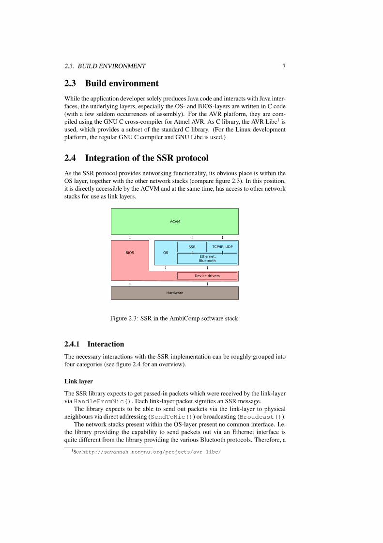
2.4 Integration of the SSR protocolAs the SSR protocol provides networking functionality, its obvious place is within theOS layer, together with the other network stacks (compare figure 2.3). In this position,it is directly accessible by the ACVM and at the same time, has access to other networkstacks for use as link layers.
Figure 2.3: SSR in the AmbiComp software stack.
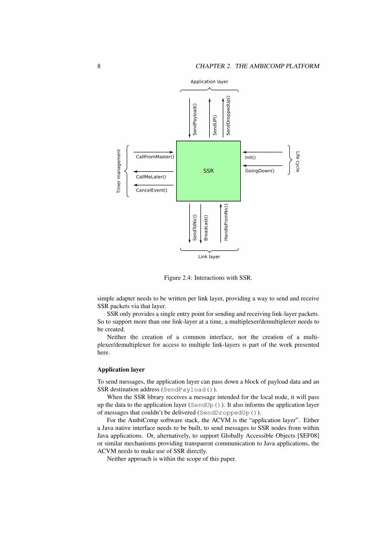
2.4.1 InteractionThe necessary interactions with the SSR implementation can be roughly grouped intofour categories (see figure 2.4 for an overview).
Link layer
The SSR library expects to get passed-in packets which were received by the link-layervia HandleFromNic(). Each link-layer packet signifies an SSR message.
The library expects to be able to send out packets via the link-layer to physicalneighbours via direct addressing (SendToNic()) or broadcasting (Broadcast()).
The network stacks present within the OS-layer present no common interface. I.e.the library providing the capability to send packets out via an Ethernet interface isquite different from the library providing the various Bluetooth protocols. Therefore, a
1See http://savannah.nongnu.org/projects/avr-libc/
8 CHAPTER 2. THE AMBICOMP PLATFORM
Figure 2.4: Interactions with SSR.
simple adapter needs to be written per link layer, providing a way to send and receiveSSR packets via that layer.
SSR only provides a single entry point for sending and receiving link-layer packets.So to support more than one link-layer at a time, a multiplexer/demultiplexer needs tobe created.
Neither the creation of a common interface, nor the creation of a multi-plexer/demultiplexer for access to multiple link-layers is part of the work presentedhere.
Application layer
To send messages, the application layer can pass down a block of payload data and anSSR destination address (SendPayload()).
When the SSR library receives a message intended for the local node, it will passup the data to the application layer (SendUp()). It also informs the application layerof messages that couldn’t be delivered (SendDroppedUp()).
For the AmbiComp software stack, the ACVM is the “application layer”. Eithera Java native interface needs to be built, to send messages to SSR nodes from withinJava applications. Or, alternatively, to support Globally Accessible Objects [SEF08]or similar mechanisms providing transparent communication to Java applications, theACVM needs to make use of SSR directly.
Neither approach is within the scope of this paper.
2.4. INTEGRATION OF THE SSR PROTOCOL 9
Timer management
SSR expects to be able to register (CallMeLater()) and unregister(CancelEvent()) timer events, allowing call-backs into the SSR code(CallFromMaster()) to occur after a requested amount of time.
The BIOS provides only a single timer event. Therefore the more sophisticatedtimer management expected by the SSR implementation needs to be provided else-where. It can either be adapted from timers provided within the ACVM or by a newlydeveloped timer library called from within the ACVM’s event queue.
A simple timer library was developed in the course of this study thesis, whichallows to be driven by the single BIOS timer event. The final integration with theACVM remains as future work.
Life-cycle management
The SSR implementation needs to initially register a few timers and announce its pres-ence to its physical neighbours via the link layer. This is done via the Init() call,which should be called when all other layers within the OS layer have been initialised.
The GoingDown() call performs the opposite operation. It announces the shut-down of the node to its physical neighbours and halts any running timers. Althoughthe SSR protocol has means to detect nodes which disappear silently, explicitly callingGoingDown() should be preferred for efficiency reasons.
2.4.2 EnvironmentThe SSR library instance needs to cope with the limitations presented by AmbiComp’shardware stack and build environment. Specifically
• the library’s code and static data need to fit into the flash memory,
• the run-time memory foot-print needs to fit into the internal or external RAM,
• the library needs to be compilable by the build environment currently used withinthe AmbiComp project.
Analysing these limitations and preparing the SSR implementation to overcomethem, is the main focus of this study thesis.

10 CHAPTER 2. THE AMBICOMP PLATFORM

Chapter 3
Introduction to ssr-core
This chapter reveals the inner workings of the SSR black-box shown in the previouschapter and introduces the main building blocks of the library.
The library implementing the SSR protocol is called ssr-core. It is written in C++and was developed in parallel to the evolving specification of the SSR protocol.
3.1 Important components
3.1.1 The nodeThe main component within ssr-core is the abstract node class. One instance of thenode class represents a single SSR node. The node class provides all entry points andhooks presented in chapter 2.4.1, i.e. it serves as the main entry point into the library.The outgoing hooks are implemented as purely virtual methods. Users of the libraryare expected to sub-class the node class and implement the purely virtual methods.
3.1.2 RoutingEach node has two types of addresses: virtual and physical addresses. A node hasexactly one virtual address, but potentially several physical addresses: one physicaladdress per available link-layer network interface.
Figure 3.1: A virtual ring of node addresses [Fuh05, fig. 1].
11
12 CHAPTER 3. INTRODUCTION TO SSR-CORE
Based on the virtual addresses, the nodes in an SSR network form a virtual ring(figure 3.1). Each node has two virtual neighbours: a predecessor and a successor inthe ring.
The list of available physical neighbours (and their respective virtual and physicaladdresses) is stored in the InterfaceStore class. It allows the routing of messages fromthe local node to a node that is a direct physical neighbour.
Messages that need to be sent beyond the node’s physical neighbours potentiallyneed more work: If the message contains a source path in its header which has a validnext hop, it is forwarded to that hop. For messages that originate from the local nodeor who’s source path does not describe a valid next hop, the node’s local routing tableis used to determine a new path.
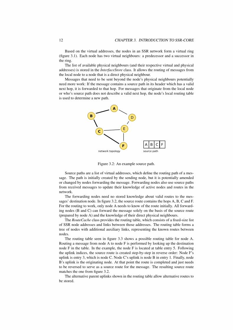
Figure 3.2: An example source path.
Source paths are a list of virtual addresses, which define the routing path of a mes-sage. The path is initially created by the sending node, but it is potentially amendedor changed by nodes forwarding the message. Forwarding nodes also use source pathsfrom received messages to update their knowledge of active nodes and routes in thenetwork.
The forwarding nodes need no stored knowledge about valid routes to the mes-sages’ destination node. In figure 3.2, the source route contains the hops A, B, C and F.For the routing to work, only node A needs to know of the route initially. All forward-ing nodes (B and C) can forward the message solely on the basis of the source route(prepared by node A) and the knowledge of their direct physical neighbours.
The RouteCache class provides the routing table, which consists of a fixed-size listof SSR node addresses and links between those addresses. The routing table forms atree of nodes with additional auxiliary links, representing the known routes betweennodes.
The routing table seen in figure 3.3 shows a possible routing table for node A.Routing a message from node A to node F is performed by looking up the destinationnode F in the table. In the example, the node F is located at table entry 5. Followingthe uplink indices, the source route is created step-by-step in reverse order: Node F’suplink is entry 3, which is node C. Node C’s uplink is node B in entry 1. Finally, nodeB’s uplink is the originating node. At that point the route is completed and just needsto be reversed to serve as a source route for the message. The resulting source routematches the one from figure 3.2.
The alternative parent uplinks shown in the routing table allow alternative routes tobe stored.

3.1. IMPORTANT COMPONENTS 13
Figure 3.3: An example routing table.
The routing table contains at least the routes to the node’s virtual predecessor andsuccessor. Assuming a correctly and fully formed virtual ring, a message can be routedto its destination simply by passing it along the virtual ring. Solely using this approachwould lead to very inefficient routing.
By storing paths to additional nodes in the routing table, the average routing stepand path length is significantly reduced. In the optimal case, the stored paths shouldlead to nodes with exponentially increasing virtual distance to the local node. Thisallows for routing steps to be, on average, within O(log N), for a network consistingof N nodes [Fuh05, p. 244].
In case the routing table does not contain a direct route to the intended destination,the message is instead forwarded to the node with the virtually closest address and theshortest hop count. These routing steps repeat until the intended destination is reachedor the closest virtual address determines, that the destination node does not exist.
3.1.3 TimersThe ssr-core library uses timers to cope with node churn within the network:
• The broadcast timer event (EventBroadcast) causes the node to regularly broad-cast its existence to all physical neighbours.
• The interface1 timeout event (EventIfTimeout) exists once per physical neigh-bour. The timer’s timeout is reset in the case of activity from the physical neigh-bour. In case of a timeout, the physical neighbour is assumed to have vanished(e.g. because it has lost power or because it has moved out of radio range) and isremoved from the InterfaceStore.
• The notification timer (EventNotification) causes the node’s virtual neighboursto be contacted. This keeps the routing table up-to-date regarding the paths to
1The term “interface” currently stands for a single physical neighbour. Originally, there were moreinterface types apart from the remaining point-to-point one and the “interface” term was more justified.

14 CHAPTER 3. INTRODUCTION TO SSR-CORE
the virtual neighbours. If the neighbour table feature is activated, the notificationmessage also includes a copy of the local neighbour table. This further improvesthe robustness of SSR in case of node churn. (See 5.3.7 for further details onneighbour tables.)
See section 5.3.4 for details on the timer events’ implementation.
3.1.4 MessagesAll communication between SSR nodes takes place in the form of SSR messages. Allmessages have a common header, which indicates the message’s type.
The MsgPayload message transports the actual data from the upper applicationlayer. All other message types are responsible for maintaining the SSR network, e.g.by announcing new nodes, invalidating specific routes, etc.
See section 5.3.11 for details on the messages.
3.2 State machineThe simplified state machine in figure 3.4 shows the states in which an SSR node canreside in. Additionally, it shows the state transitions. The transitions are caused bythe incoming function calls Init(), GoingDown(), CallFromMaster() andHandleFromNic().
Figure 3.4: Simplified state machine, documenting the states of an SSR node.
The states implicitly result from the contents of the node’s routing table and inter-face store. They are not explicitly modeled within the library.
On Init() an SSR node changes from state SSRConstr to state SSRIsoMax. Atthis point, all timers have been set and the node has announced its existence to the directphysical neighbours. It does not yet know of any neighbours and therefore remainsisolated. Additionally, due to its isolation, the node’s address is the highest knownaddress in the (empty) virtual ring.
3.2. STATE MACHINE 15
The the node’s shutdown is caused by calling GoingDown(), in which case thestate changes to the final state SSRShutd, regardless of the previous state. Any physicalneighbours are now informed about the node’s removal and all timers are disabled.
The events shown on the state diagram are timer events and are triggered by theCallFromMaster() function, which is the call-back for timers that were previouslyregistered by ssr-core and have timed out. The only timer event relevant for statechanges is the interface timeout event.
The messages shown are SSR messages, received via HandleFromNic(). AnySSR message routed through the SSR node can implicitly change the state of the SSRnode. This is due to updates to the routing table from source paths stored within theSSR messages. The SSR messages explicitly changing the node’s state are MsgHello,MsgKill, MsgRouteUpdate, MsgNeighborNotification and MsgMaxNodeAnnounce.
During regular operation, the SSR node is either in state SSRMax or in state SSR,depending on whether it has the largest address in the virtual ring or not2. Interfacetimeouts and Kill messages can lead back to the nodes isolation (SSRIsoMax) or itcould turn the node into the node with the largest address (SSRMax). The introductionof new nodes might lead to a change from state SSRMax to state SSR, if one of the newnodes has a higher virtual address.
Detailed information regarding the state machine is given in section 5.2.
2Specifically, it checks whether the node’s virtual successor has a lower virtual address than the localnode.

16 CHAPTER 3. INTRODUCTION TO SSR-CORE

Chapter 4
Changes to ssr-core
This chapter describes the changes applied to the ssr-core library in the course of thestudy thesis. The changes can be roughly categorised into two groups: One groupof changes was made necessary by the fact that the library needed to be ported to anew platform. The other group of changes had to do with general code maintenance.The changes in the former group will be thoroughly documented in this chapter. Thechanges in the latter group will be presented in far less detail, as they were mainlyimplementation work without much academical value.
As described in chapter 2, the library needed to be ported to the AVR platformand its build environment. Before this porting effort, the ssr-core library had beenintegrated and tested with simulation frameworks like OMNet++ 1 and run on reg-ular desktop PCs. In addition, for the Linyphi project [DEF08], the implementationhad been ported to small Linux-based routers running on MIPS processors [DEF08, p.685]. Compared to the targeted AVR platform, both previous environments providedrelatively large amounts of RAM and had build environments without restrictions to theavailable tool-set. To make the code-base usable within AmbiComp’s OS layer and onthe AVR platform, it needed changes regarding the used C++ feature-set, the memoryusage and memory management and its code size.
The following sections will analyse which aspects of the implementation neededchanges. They will then develop possible solutions for each aspect and finally presentthe chosen solution.
4.1 Avoiding heap memory and the STLThe SSR protocol stack will reside within the OS layer of the ACVM. The OS andBIOS layers don’t provide regular malloc() and free() functions. Instead, al-locations on the stack, static allocations or specific memory assignments at link-timehave to be used. So the use of malloc() and free() needs to be removed anddynamic memory allocations should be replaced or avoided as much as possible.
In the following sub-sections, central structures or repetitive patterns using dynamicmemory allocations will be analysed. Based on the analyses, approaches for replacingthe dynamic allocations with storage on the stack or static allocations will be presented.Every sub-section will conclude with the approach chosen for the new ssr-core imple-mentation, when configured for the AVR platform.
1http://www.omnetpp.org/
17

18 CHAPTER 4. CHANGES TO SSR-CORE
In addition to the memory allocation restrictions, the AVR platform does not pro-vide any C++ libraries. Specifically, the STL is not included and including it wouldcause the code-size to increase dramatically. Therefore, any code using STL constructsis analysed and approaches for replacement are discussed.
4.1.1 SSR messagesProblem
The SSR message classes represent the protocol’s messages sent over the network be-tween SSR nodes (e.g. payload messages, hello messages, etc.). The classes can seri-alise and deserialise themselves.
All SSR messages are created dynamically. Their life-time is restricted to calls intothe SSR core, i.e. they get created during an SSR core method call and get releasedbefore its return. So in theory, many dynamic allocations could be replaced by placingthe objects on the stack.
Unfortunately, messages retrieved (i.e. deserialised) from the network are turnedinto objects by a factory method. In addition the (optional) neighbour table distributionrequires SSR message cloning functionality. Both features aren’t easily transferred tostatic or stack-based allocations.
Without an extensive design change, the only viable approach is one, that emulatesdynamic memory allocation without using a regular heap. The allocation mechanismwould only need to provide space for a very small number of messages and couldtherefore work from a statically allocated buffer of fixed size.
Solution
The new implementation follows the dynamic memory allocation approach. It doesthis by using a cStaticPool<>-based cMessagePool, which is a statically sizedand allocated message pool, providing N blocks of equal size for the storage of Nmessages2. The syntax of message allocations is unchanged, as the pool is connected tothe base message class through operator new and operator delete methods.The latter aspect kept the amount of work needed to implement the change very low.
4.1.2 SSR payload messagesProblem
The payload messages are the messages containing the actual data, i.e. they transportthe data sent by the layer above the SSR protocol. Due to the large payload buffer,these messages are – by far – the largest messages among all SSR messages and wouldthus waste a lot of memory in the cMessagePool, which was proposed as solutionabove.
As mentioned in section 4.1.1, a message’s life-time is restricted to call into the SSRcore. While processing a payload message, the SSR core does not create an additionalone, so no two payload messages will be handled at the same time. Therefore a globalstatic payload buffer would be able to replace the dynamically allocated buffers.
2The block size is equal to the largest message size. The largest message size is determined at compile-time, using a list of all message classes in MessagePool.cc. Space for 2 messages is reserved, as ssr-core onlyprocesses one incoming message at a time and creates a maximum of one additional message as response,i.e. never needs space for more than 2 messages at a time.
4.1. AVOIDING HEAP MEMORY AND THE STL 19
Alternatively, instead of creating a private copy, the storage could also be avoidedcompletely by reusing the original buffer containing the payload.
Solution
The latter approach was used in the new implementation. The payload buffer pointerwas modified to point to a constant buffer, i.e. the library modifies the data and applica-tions which get handed the payload may not modify it either. This allowed the payloadmessage class to reuse the raw incoming buffer from the callee, simply pointing fromwithin the message instance into the raw buffer. The approach completely avoids anybuffer copying and therefore also avoids the memory allocation problem.
In case the message comes from the network, the payload pointer points into thenetwork buffer. In case it comes from the application, the pointer refers to the buffersupplied by the application. The pointer’s constness assures, that no modifications areapplied.
4.1.3 SSR timer eventsProblem
As mentioned previously, SSR’s timer event system uses event class instances to reg-ularly send broadcasts, to watch out for physical neighbour timeouts (called interfacetimeouts) and to keep its virtual neighbours updated.
The event objects are created dynamically and get passed out of SSR core as trans-parent pointers (via CallMeLater()). They therefore have a life-time that exceedsSSR core method calls, ruling out the possibility of using stack-based storage.
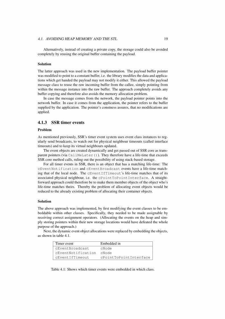
For all timer events in SSR, there is an object that has a matching life-time: ThecEventNotification and cEventBroadcast events have a life-time match-ing that of the local node. The cEventIfTimeout’s life-time matches that of itsassociated physical neighbour, i.e. the cPointToPointInterface. A straight-forward approach could therefore be to make them member objects of the object who’slife-time matches theirs. Thereby the problem of allocating event objects would bereduced to the already existing problem of allocating their container objects.
Solution
The above approach was implemented, by first modifying the event classes to be em-beddable within other classes. Specifically, they needed to be made assignable byreceiving correct assignment operators. (Allocating the events on the heap and sim-ply storing pointers within their new storage locations would have defeated the wholepurpose of the approach.)
Next, the dynamic event object allocations were replaced by embedding the objects,as shown in table 4.1.
Timer event Embedded incEventBroadcast cNodecEventNotification cNodecEventIfTimeout cPointToPointInterface
Table 4.1: Shows which timer events were embedded in which class.
20 CHAPTER 4. CHANGES TO SSR-CORE
In addition, the timer event system needed a way to inform the external event loopof timers that should be disabled. Therefore the new call-back CancelEvent wasintroduced. To ease the event management, an additional void* handle property wasadded to the events, to allow the external event loop to store a local identifier.
4.1.4 NIC addressesProblem
SSR uses a small data block to transparently represent local physical addresses withinthe SSR core. SSR does not interpret the NIC address internally, i.e. they are onlymeaningful to the caller. The data blocks are copied into dynamically sized and allo-cated buffers.
As the physical address size typically depends on the used interface types (e.g. 48bit Ethernet hardware addresses or 64 bit ZigBee addresses) and we will know the usedinterface types at compile-time, the dynamic allocations can be replaced with buffersof fixed size.
Solution
In the new implementation, the pointers to dynamic memory were replaced withcNicAddr wrapper objects which can use an internal, embedded buffer of static sizeto store the address (if configured to use the cStaticNicAddr storage back-end,see section 5.1.2). The class is implemented as a value type (i.e. the instances can becopied or assigned similar to built-in C++ types), so all dynamic memory usage can beavoided.
4.1.5 Interface tableProblem
The interface table maps SSR node addresses (i.e. virtual addresses) of all knownphysical neighbours to a cPointToPointInterface instance, which containsfurther information about the neighbor (e.g. the link-layer address). The table usesa std::map without any size limitations. This needs to be replaced with an approachnot depending on the STL and not requiring heap memory.
Any non-dynamic approach unavoidably restricts the number of physical neigh-bours stored in the table. Therefore a mechanism needs to be designed, that decideswhat to do with newly detected neighbours while the neighbour table has no space left.
A complete analysis of the possible approaches is not within the scope of this thesis.
Solution
The ported ssr-core library uses a fixed-size list of interfaces instead of the std::map,aiming for simplicity in implementation. The interface size is defined at compile-time.No replacement strategy is used, so interface announcements will be dropped if moreinterfaces are active than allowed for at compile-time.
4.1. AVOIDING HEAP MEMORY AND THE STL 21
4.1.6 Routing tableProblem
The routing table is an array of SSR nodes, containing information about parent / childrelationships and when each entry was last used in a routing decision.
The routing table is well prepared for the necessary conversion to static memoryallocation, as all memory is allocated via the new[] operator at construction time andcan be easily replaced with a embedded arrays of fixed size.
Solution
All involved routing table member types are made embeddable and the allocated arraysare replaced with arrays of fixed size, which are embedded within the routing tableclass (cStaticCacheCore). The size, i.e. the number of routing entries, is definedat compile-time (see section 5.1.2).
4.1.7 Neighbour tableProblem
The neighbour table storage has no dynamic elements and does not use the STL. Theimplementation is incomplete though (see 5.3.7), so this code section could be madeoptional.
Solution
The code supporting the neighbour table feature is enclosed within the preprocessorsymbol SSR_WITH_NEIGHBOR_TABLE and disabled for the AVR target to minimisethe code-size.
4.1.8 Source pathsProblem
Source paths consist of a list of virtual node addresses that can be traversed to reach acertain target node. Within ssr-core such paths are stored in cPath objects.
The cPath objects are used on the stack, as return values and embedded in mes-sage objects. The life-times of the reference-counted paths is very diverse.
The old cPath implementation stores the path in a dynamically allocated andreference-counted memory buffer, allowing for unrestricted path lengths.
Assuming that a maximum path length can be determined at compile-time, a bufferof fixed size could be used for the path.
Ignoring the existing reference-counted approach, this buffer could be embeddeddirectly within the cPath object. The benefit would be that out-of-memory (OOM)conditions could be handled easier: The allocations would already fail when allocatingthe cPath instance instead of later on, within the cPath constructors. An additionalbenefit would be, that the required code for the embedded buffer approach would bevery simple.
As cPath objects are passed by value with-in ssr-core, the obvious down-side tothe above approach would be the frequent copying of the path lists, possibly causing
22 CHAPTER 4. CHANGES TO SSR-CORE
performance problems. Another problem could be the increased memory usage due tomultiple copies of the same path using up memory.
A different approach is to continue supporting the reference counted approach. In-stead of dynamic allocation from the heap one could use a central fixed-size pool offixed-size source path lists which could then be shared between all cPath objects.This would avoid the frequent copying, but could lead to out-of-memory conditionsdue to an insufficient pool size, i.e. due to more paths allocated than available in thepool.
Any solution not assuming fixed-length paths would require far more complexmemory management functions or the use of dynamic memory provided by the ACVM.
Solution
For the new implementation, the reference-counted approach with fixed maximum pathlengths was chosen to optimise for speed and memory usage, while assuming well-chosen path lengths and pool sizes. The fixed-size source paths are stored in a staticallyallocated cStaticPool<>.
It remains unclear whether a fixed-length path structure is a viable long-term solu-tion.
4.1.9 Maximum nodeProblem
To avoid disjoint rings, a node who’s virtual address is higher than its successor’s (i.e.has the highest address in the virtual ring) needs to broadcast this information usingcMsgMaxNodeAnnounce messages [CF05, sec. 2.3]. The messages are floodedthrough-out the SSR network.
On receiving such a message, the virtual address of the message originator (i.e. ofthe node that initially sent the message and has the highest virtual address) is stored ina std::set. If the same node address already exists in the set, the message won’t beprocessed.
This prevents the node from processing the same information multiple times andstops the message from being endlessly flooded back and forth through the network.
An approach to get rid of the std::set, would be to use a static queue of the lastL maximum node announcements.
Solution
To resolve the problem, the maximum node announcement storage was split out intoa class that uses a queue of fixed length to keep track of the last L maximum nodeannouncements.
4.2 Reducing and choosing table sizesAs the hardware used by the AmbiComp project has limited memory resources, alllarge data structures need to be analysed, so that their size can be reduced as far aspossible.
Some structures already have a default size in the old ssr-core implementation. Itwill be determined whether that size can be reduced.
4.2. REDUCING AND CHOOSING TABLE SIZES 23
Additionally, a few data structures were previously dynamically sized. Therefore,appropriate static sizes for these previously dynamically sized structures need to befound.
4.2.1 Interface tableDepending on which interface types are compiled in and the expected device density,the optimal interface table size will vary widely.
E.g. a wired ethernet interface connected to a switched network can theoreticallyhave an almost unlimited number of physical neighbours. Estimating a useful interfacetable size is very difficult in this case and will have to be based on an assumed deploy-ment environment (i.e. expected number of neighbours in the specific environment).
The number of physical neighbours of a wireless interface is easier to foresee, asthere are restrictions on the radio’s range and (e.g. for Bluetooth piconets) on thenumber of simultaneous communication partners.3
Depending on the interface types involved, the assumed number of neighbours willalways be arbitrary. A one-size-fits-all value seems unlikely, so this parameter willneed to be adjusted depending on the device’s intended environment.
During past simulations performed by Pengfei Di with the SSR protocol, nodes hadno more than 20 physical neighbours at a time, so 20 will be used as a default table sizefor AmbiComp’s implementation.
More tests should be performed to determine typical average numbers of physicalneighbours depending on node density, to allow educated guesses for a specific envi-ronment.
4.2.2 Source pathsThe SSR protocol and the AmbiComp project both assume a random, distributed Ad-Hoc sensor network. In these types of networks, the worst case node topology, whereall nodes are chained together in a long line, is assumed to be very unlikely. Even anetwork forming a unit disk graph induces potentially long average paths: O(
√N ).
According to [Fuh05, p. 248], small-world network scenarios have far shorter av-erage path lengths. Assuming such a scenario, it is still unclear what specific values tochoose, especially during earlier phases of the network setup boot-strap.
The actually necessary sizes will need to be determined by further simulations.The implementation now reserves space for path lengths of 30 hops, which should bea safely high number of hops for small-world scenarios.
4.2.3 Routing tableThe routing table contains SSR nodes, organised in a tree structure. The links in thetree represent known routing paths. The tree is stored as an array, where each arrayelement represents a single node with information about parent / child relationshipsand when each entry was last used in a routing decision (compare figure 4.2).
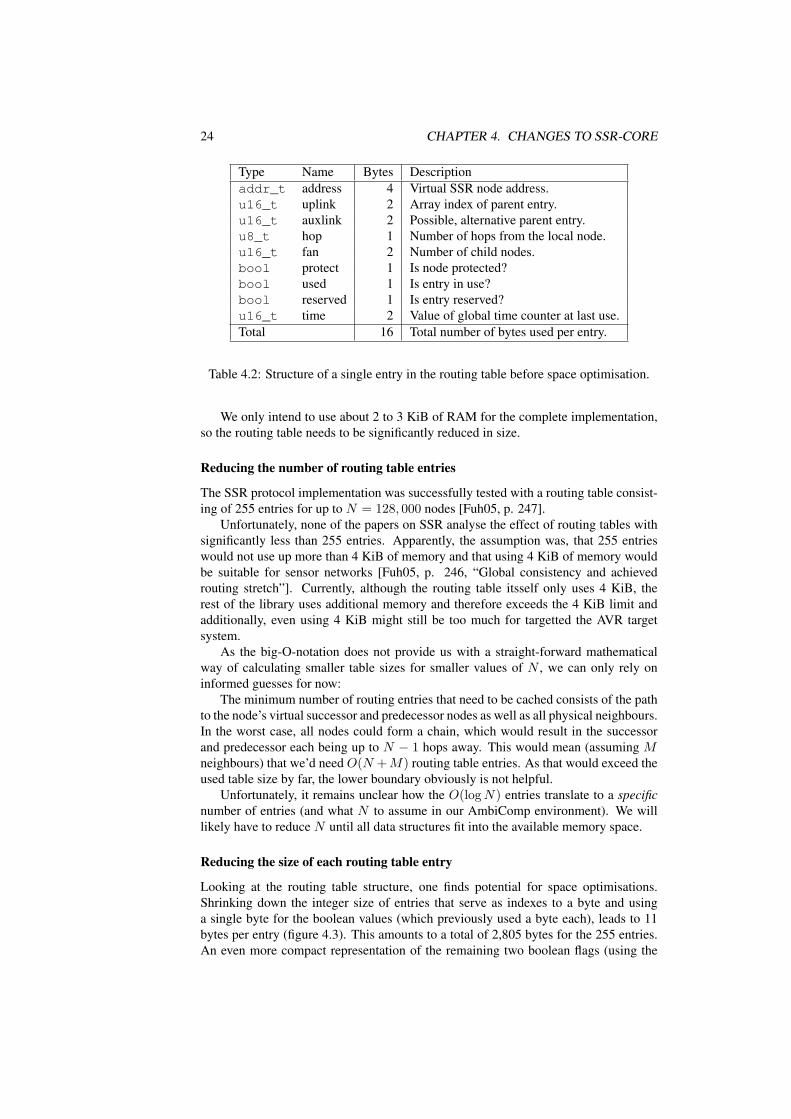
The SSR protocol assumes O(log N) routing table entries in a network with Nnodes [Fuh05, p. 240]. For the old ssr-core implementation, each entry (i.e. routingtable line) was 18 bytes large (see figure 4.2). The implementation always used 255entries and therefore required 4,080 bytes of RAM for the routing table entries alone.
3Depending on whether the Bluetooth stack supports scatternets, this limitation could be circumvented.In theory, there’s no real limitation, but real-world implementations are often restricted in their capabilities.
24 CHAPTER 4. CHANGES TO SSR-CORE
Type Name Bytes Descriptionaddr_t address 4 Virtual SSR node address.u16_t uplink 2 Array index of parent entry.u16_t auxlink 2 Possible, alternative parent entry.u8_t hop 1 Number of hops from the local node.u16_t fan 2 Number of child nodes.bool protect 1 Is node protected?bool used 1 Is entry in use?bool reserved 1 Is entry reserved?u16_t time 2 Value of global time counter at last use.Total 16 Total number of bytes used per entry.
Table 4.2: Structure of a single entry in the routing table before space optimisation.
We only intend to use about 2 to 3 KiB of RAM for the complete implementation,so the routing table needs to be significantly reduced in size.
Reducing the number of routing table entries
The SSR protocol implementation was successfully tested with a routing table consist-ing of 255 entries for up to N = 128, 000 nodes [Fuh05, p. 247].
Unfortunately, none of the papers on SSR analyse the effect of routing tables withsignificantly less than 255 entries. Apparently, the assumption was, that 255 entrieswould not use up more than 4 KiB of memory and that using 4 KiB of memory wouldbe suitable for sensor networks [Fuh05, p. 246, “Global consistency and achievedrouting stretch”]. Currently, although the routing table itsself only uses 4 KiB, therest of the library uses additional memory and therefore exceeds the 4 KiB limit andadditionally, even using 4 KiB might still be too much for targetted the AVR targetsystem.
As the big-O-notation does not provide us with a straight-forward mathematicalway of calculating smaller table sizes for smaller values of N , we can only rely oninformed guesses for now:
The minimum number of routing entries that need to be cached consists of the pathto the node’s virtual successor and predecessor nodes as well as all physical neighbours.In the worst case, all nodes could form a chain, which would result in the successorand predecessor each being up to N − 1 hops away. This would mean (assuming Mneighbours) that we’d need O(N +M) routing table entries. As that would exceed theused table size by far, the lower boundary obviously is not helpful.
Unfortunately, it remains unclear how the O(log N) entries translate to a specificnumber of entries (and what N to assume in our AmbiComp environment). We willlikely have to reduce N until all data structures fit into the available memory space.
Reducing the size of each routing table entry
Looking at the routing table structure, one finds potential for space optimisations.Shrinking down the integer size of entries that serve as indexes to a byte and usinga single byte for the boolean values (which previously used a byte each), leads to 11bytes per entry (figure 4.3). This amounts to a total of 2,805 bytes for the 255 entries.An even more compact representation of the remaining two boolean flags (using the

4.3. EXCEPTIONS 25
newly written cBitFieldArray, a structure that uses one bit per boolean entry),saves another 159 bytes. As the code made no use of the protect flag, it can be removedcompletely, saving yet another 31 bytes. After all optimisations, the table is 10.25 bytesper entry, amounting to 2,613 bytes for 255 entries.
type name bytesaddr_t address 4u8_t uplink 1u8_t auxlink 1u8_t hop 1u8_t fan 1bool used 0.5 (0.125)bool reserved 0.5 (0.125)u16_t time 2Total 11 (10.25)
Table 4.3: Structure of a single entry in the routing table after space optimisation.
4.3 ExceptionsAs the AVR target-environment currently misses support for exceptions, that C++ fea-ture needed to be removed from the ssr-core library. Exceptions were used through-outthe code for out-of-memory (OOM) conditions, various internal error states and evenabused to indicate the successful delivery of a message4.
4.3.1 Errno valueAn approach similar to libc’s errno was chosen: A thread-specific error number vari-able, accessable via global SetErrno() and GetErrno()methods was introduced.This is used to provide detailed information about the last error.
Functions originally without return value now return a boolean value indicatingfailure or success and set the Errno value appropriately. To easily identify legacy codethat does not check the return value, the attribute SSR_MUST_CHECK_RETVAL isintroduced to enable compile-time warnings.
Functions which already returned a value needed to be modified to return an obvi-ously invalid value for the error case. To allow this, a few types needed to be enhanced.E.g. cPath::zero and cNicAddr::zero were introduced.
4.3.2 Exceptions from constructorsOne class of exceptions could not be easily replaced: Exceptions thrown from con-structors. Constructors cannot return an error value, so there’s no easy way for themto indicate an error. A typical approach to reporting errors in constructors is to movethe actual work into an init function. That function would then be able to indicateinitialisation errors through regular return values.
4The DestinationReachedException was used to indicate that a message had reached its destination.

26 CHAPTER 4. CHANGES TO SSR-CORE
For the old and new code, this problem affects the cPath classes. The constructorsattempt memory allocations and cannot indicate or resolve OOM conditions gracefully.Unfortunately, the cPath classes are used in hundreds of different places through-outthe code (routing code, message handling, etc.), making the proposed init-function-approach very work-intensive.
It is assumed, that OOM conditions can be avoided for controlled network envi-ronments, so for now, the library calls SSR_ERROR() (typically causing std::abort tobe called) on OOM conditions. This temporary approach allows the exceptions to beremoved without the need for a lot of redesign work.
4.4 Run-Time Type IdentificationAlthough the target platform supports RTTI, the feature is disabled by default. Whenactivated, the feature would requires a few additional bytes per class and shouldtherefore be avoided if possible. The old code uses RTTI through the use ofdynamic_cast<> to determine the type of message classes. As every message al-ready has an embedded type ID5, this can be used as type information instead.
Therefore, in the new ssr-core implementation all dynamic_cast<>s were re-placed with checks against getID() or a few helpers6 and static_cast<>s.
Ideally, the functionality using explicit message type tests should be refactored intovirtual methods of the cMessage class, so that explicit type checks are no longernecessary. The refactoring was not performed and remains as future work.
4.5 Removing inliningThe goal of removing the inlining used within the old code-base was to reduce thecode size. Currently, small code-size is more important for the use-cases of the ssr-core library than speed, especially for the AVR platform.
The old implementation inlined large portions of the code either implicitly, by em-bedding the code within the class definition in the class’ header file, or explicitly bydefining the method in the header and using the inline keyword.
Both of these inlining approaches were removed from the new code-base. Allmethod implementations now reside within the implementation files (*.cc), i.e. theheader files (*.hh) only contain the class declarations and definitions.
This is true even for template classes. The template classes’ implementation wasmoved to *.inl files. These template inline files are included in *.cc files, wherethe template classes are then explicitly instantiated7.
As can be seen in table 4.4, removing inlining saved 98, 152 − 84, 320 = 13, 832bytes, i.e. the approach was rather successfull.
The table’s text column signifies the code size, the data column represents the sizeof the initialised static data and the BSS column represents the size of the uninitialisedstatic data. The total is the total space used on the flash. As the code is not loaded tothe RAM, the text column has no influence on the RAM usage.
5The ID is defined in the enum tMessageType and is used in serialised messages to determine the type.6IsMsgConnect() and IsMsgHopByHop are helpers to support checking against the messages’ class hier-
archy.7For explicit template instantiation in C++, see e.g. http://msdn.microsoft.com/en-us/
library/by56e477.aspx

4.6. CODE RENOVATION 27
Text Data BSS Total Inlining cBitFieldArray92928 1094 4130 98152 with without94820 1094 3872 99786 with with79584 702 4034 84320 without without79652 702 3872 84226 without with
Table 4.4: Code and data sizes of ssr-core in bytes – before and after removing exces-sive inlining.
The cBitFieldArray is a template class minimising the size of the routingtable (see section 4.2.3). As can be seen from the table and the earlier section onrouting table shrinking, the space used on the flash increases by only 68 bytes, whilesaving 159 bytes of RAM.
4.6 Code renovationPrevious to the porting work described in this paper, the ssr-core code-base was diffi-cult to understand. Before analysing the code, a thorough code cleanup was performed.
This involved:
• Applying a consistent coding style to the code. This included the renaming ofclasses, functions and member variables as well as applying consistent indenta-tion.
• The detection and removal of unused code and unused variables.
• The normalisation of class hierarchies. Specifically, the node classes were pulledtogether into a single abstract node class. Previously, the various classes weredivided into parent and base classes, but followed no abstraction between one-another, which only caused confusion and unnecessary up-castings.
• Making various methods either non-virtual or purely virtual to clearly documentthe intended usage through C++ language features.
• Splitting up the header and implementation files into one header and one im-plementation file per class. Previously, the classes were organised in only ahand-full of header and implementation files, which made navigating the classesdifficult.
• Creating a Makefile based build system, that properly handled incremental re-builds and supported building for several target platforms.
• Improving the automated testing of the code and integrating the unit testing intothe build system. (See chapter 6 for details.)
• Introducing an SSR namespace to allow intuitive naming of the implementa-tion’s classes without fearing collisions with application code. Any existingSSR-prefixes in class names were removed.

28 CHAPTER 4. CHANGES TO SSR-CORE

Chapter 5
The new ssr-core library
This chapter provides a detailed configuration-, state- as well as class-level overviewof the reworked ssr-core implementation.
5.1 Code configurationThe ssr-core library is designed to be usable in different applications and environmentswithout the need for code modifications. Therefore only one code-base needs to bemaintained and all applications and platforms profit from any fixes or enhancementsadded to the code.
The flexibility necessary to achieve the above goal is reached through two ap-proaches, which are detailed below.
5.1.1 Abstract cNode classThe library provides an abstract cNode class with purely virtual methods perform-ing application and system specific operations. This includes sending and receivingnetwork packets on the link layer, handling of the payload data, timer handling andmore. A new application therefore only needs to sub-class and implement the abstractcNode class and does not need to modify the ssr-core library itsself. The child classwill most likely act as adapter class, relaying actions between the application and theenvironment through itsself to cNode, as shown in figure 5.1.
Figure 5.1: Users of the ssr-core library need to sub-class the abstract Node class.
29

30 CHAPTER 5. THE NEW SSR-CORE LIBRARY
5.1.2 Compile-time optionsTo enable or disable certain code-paths within the library, preprocessor symbols areused.
The preprocessor symbols listed in table 5.1 can be defined (or left undefined) inthe target directory’s config.hh file.
The study thesis added all compile-time options apart from SSR_WITH_DEBUG.The concept of one config.hh file per target, containing all config preprocessorsymbols, was also newly introduced.
Preprocessor symbol DescriptionSSR_WITH_DEBUG Enable debugging.SSR_WITH_SIMULATION_SUPPORT Enable methods and settings relevant for
simulating the code with OMNeT++.SSR_WITH_STATIC_TABLES Activate static tables.SSR_WITH_NEIGHBOR_TABLE Enable support for the neighbour table fea-
ture.SSR_HAS_STL Platform provides support for STL.SSR_HAS_HEAP Platform provides heap memory.SSR_HAS_EXCEPTIONS Architecture has support for exceptions.SSR_HAS_TLS Architecture has thread-local storage.SSR_SET_NUM_SIMULTANEOUS_MSGS Number of messages expected to be instan-
tiated at once.SSR_SET_NIC_ADDR_SIZE Size of link-layer addresses for physical
neighbours in bytes.SSR_SET_ADDR_SIZE Size of virtual node addresses in double
words (4 bytes).SSR_SET_CACHE_CORE_SIZE Number of entries within the routing table.
Table 5.1: Reflexive edges on the SSR state.
Switches either indicate features available or unavailable on a specific plat-form (SSR_HAS_*), control optional functionality within the ssr-core library(SSR_WITH_*) or set certain configuration values (SSR_SET_*).
Note: In case the existence of a class or the relationship between classes dependson the above symbols, the following diagrams are coloured appropriately.
As described in section 4.1, dynamic classes where replaced with static variants forthe AVR platform. The dynamic and static code-paths are disabled or enabled by theabove mentioned preprocessor symbols. To avoid littering the code with preprocessor#ifdefs, the code was most often refactored into two separate classes: One classproviding the dynamic approach – often using the STL – and one class providing thestatic one with fixed table sizes.
The dynamic code parts are compiled as long as the platform provides the necessaryfeatures. E.g. symbol SSR_HAS_STL and symbol SSR_HAS_HEAP are very oftennecessary for the dynamically sized structures. The static code variants are activated aslong as SSR_WITH_STATIC_TABLES is specified.
The idea behind allowing both code paths to be activated at the same time is toallow the compile-testing of both code-paths on a single build target. This can quicklyreveal obvious bugs during development.

5.2. STATE MACHINE 31
Thread-local storage is optionally used for the storage of error numbers (seesection 4.3.1) in thread-specific memory. If the platform has support for it andSSR_WITH_STATIC_TABLES is disabled, multiple threads can each run an instanceof cNode.
If a switch configuration is chosen that does not allow the library to work, an erroris displayed at compile-time. An example for such an errornous configuration wouldbe disabling SSR_WITH_STATIC_TABLES and SSR_HAS_HEAP at the same time.
5.2 State machineAs already mentioned in section 3.2, the ssr-core library neither has explicit states noran explicit state machine. The state machine in figure 5.2 none-the-less attempts todocument the major implied states in which the SSR node can reside.
Figure 5.2: State machine, documenting the states of an SSR node.
The states are implied by the entries contained within the routing table, by theinterface table (section 5.3.6 and by the object life-cycle of the node object (section5.3.1).
Details on the names and abbreviations used within the state diagram are given intable 5.2. The states are explained in the following sub-sections.

32 CHAPTER 5. THE NEW SSR-CORE LIBRARY
Event name Event classEvIT cSsrEventIfTimeout
Message name Message classMsgH cMsgHelloMsgK cMsgKillMsgMNA cMsgMaxNodeAnnounce
Condition name DescriptionLIF Last interface, there was only one interface left.MaxNo The local node now has the max virtual address in the
known ring.Entry point DescriptionInit() Initialises the node, activates various timers and an-
nounces the nodes existence.GoingDown() Notify the network, that this node is shutting down.delete Destruct the node instance.
Table 5.2: Abbreviations used within the state machine.
5.2.1 State SSRConstrThe SSRConstr state is the initial state directly after construction of an SSR node. Onlythe basic initialisations have been performed, no timers are active and the physicalneighbours know nothing of this new node.
As soon as Init() is called, the node transitions to state SSRIsoMax and acMsgHello message is broadcast via cNode::Broadcast(), to announce thenode’s existance.
5.2.2 State SSRIsoMaxIn the SSRIsoMax state, the node is isolated. It has no known physical neighbours andtherefore the known network is empty, apart from itsself (i.e. the routing table andthe interface store are both completely empty). The virtual ring has the local node asits only member, which means that the local node is the node with the highest virtualaddress.
The SSRIsoMax state is the initial state directly after initialising the node. At thatpoint, none of the potential neighbours had the opportunity to announce themselvesyet.
The state is left as soon as one of the physical neighbours reacts to the regularlybroadcasted hello messages (or if one of the neighbours hello messages is received).
The state can of course be reached again at a later point in time, if all known phys-ical neighbours disconnect or go out of range.
The timer events and entry-points documented in table 5.3 cause no state changesand are therefore reflexive edges on the state.
5.2.3 State SSRMaxIn the SSRMax state, the node has the largest virtual address in the known virtual ring.The node regularly broadcasts this knowledge to the whole network.

5.2. STATE MACHINE 33
Incoming event ActioncSsrEventNotification NonecSsrEventBroadcast send cMsgHelloEntry point ActionSendPayload() call SendDroppedUp()SendPayload() call SendUp()
Table 5.3: Reflexive edges on the SSRIsoMax state.
Apart from having the highest virtual address in the SSR network, the state is equalto the SSR state, see below.
In case a message is received, which indicates that there is another node with ahigher virtual address, the state transitions to the SSR state.
In case all physical neighbours are lost, the state transitions back to the SSRIsoMaxstate.
The timer events, messages and entry-points documented in table 5.4 cause no statechanges and are therefore reflexive edges on the state.
Incoming event ActioncSsrEventNotification send cMsgMaxNodeAnnounce and
cMsgNeighborNotificationcSsrEventBroadcast send cMsgHellocSsrEventIfTimeout and more thanone interface left
None
Entry point ActionSendPayload() for remote node send cMsgPayloadSendPayload() for unreachable node call SendDroppedUp()SendPayload() for local node call SendUp()Incoming message ActioncMsgPayload for remote node cMsgPayloadcMsgPayload for unreachable node ifnot marked as routed
SendDroppedUp()
cMsgPayload for unreachable node ifmarked as routed
SendUp()
cMsgPayload for local node SendUp()
Table 5.4: Reflexive edges on the SSRMax state.
5.2.4 State SSRThe SSR state is the state in which most nodes within the SSR network will reside mostof the time. The node has knowledge of other SSR nodes within the network. It is notthe node with the largest virtual address (see state SSRMax).
Sending and receiving messages is possible and the sent messages should be ableto reach their destinations.
34 CHAPTER 5. THE NEW SSR-CORE LIBRARY
The following timer events, messages and entry-points cause no state changes andare therefore reflexive edges on the state:
Incoming event ActioncSsrEventNotification send cMsgNeighborNotificationcSsrEventBroadcast send cMsgHellocSsrEventIfTimeout and more thanone interface left and not the maximumnode
None
Entry point ActionSendPayload() for remote node send cMsgPayloadSendPayload() for unreachable node call SendDroppedUp()SendPayload() for local node call SendUp()Incoming message ActioncMsgPayload for remote node cMsgPayloadcMsgPayload for unreachable node ifnot marked as routed
SendDroppedUp()
cMsgPayload for unreachable node ifmarked as routed
SendUp()
cMsgPayload for local node SendUp()
Table 5.5: Reflexive edges on the SSR state.
5.2.5 State SSRShutdIn the SSRShutd state, the node was deregistered from the SSR network. All timers areinactive. No messages can be received or processed.
State transitions to this state cause cMsgKill to be broadcast to all physical neigh-bours.
5.2.6 State SSRDestrIn the SSRDestr state, the node instance was destructed and its memory freed. Alltimers are inactive. No messages can be received or processed.
5.3 Class diagrams
5.3.1 cNode
class cNode
Figure 5.3: Class hierarchy of class cNode.
The cNode class as seen in figure 5.3 is an abstract class representing an SSR nodein the network. Most library interaction is performed through this class.

5.3. CLASS DIAGRAMS 35
The class provides a set of pure-virtual methods through which the node commu-nicates with the upper and lower layers. Users of the library are expected to sub-classcNode and implement the virtual methods. This allows to adapt the ssr-core library tomany different environments.
See section 2.4.1 for a detailed description of the expected interactions.
5.3.2 cRouteCache
class cDynamicCacheCoreclass cStaticCacheCore
typedef tConfiguredCacheStorage
class cRouteCache class cCacheCorecache
!SSR_WITH_STATIC_TABLES
Figure 5.4: Class hierarchy of class cRouteCache.
A cNode instance, as seen in figure 5.4, maintains one instance ofcRouteCache. It maintains the node’s routing table. It contains cCacheCore as amember element, which contains all known source routes in a tree-like structure (seesection 4.2.3).
The class contains all routing, path updating and merging logic. The actual storageof the source route elements, i.e. the known routing hops, is performed by the cachemember of type cCacheCore.
The cCacheCore has two storage options: One option is to allocate memory onthe heap (using cDynamicCacheCore). The other option is to use a fixed-size em-bedded member variable (using cStaticCacheCore). The latter option effectivelycauses the memory to be embedded within the cRouteCache instance, which itsselfis embedded within the cNode instance.
The cDynamicCacheCore class is only built if SSR_HAS_HEAPand SSR_HAS_EXCEPTIONS are enabled. And depending on whetherSSR_WITH_STATIC_TABLES is defined or not, cStaticCacheCore orcDynamicCacheCore are used as storage.
5.3.3 BitFieldArrayThe cBitFieldArray template class, as seen in figure 5.5, provides an array ofN elements, each providing storage for NUM_BITS number of bits. The storage isoptimised for space. Single bits within the list can be read or written. Read and writecomplexity is within O(1).
The class allows to select from two storage types: cDynamicBitFieldArrayallows N to be specified at run-time and stores the elements in heap memory.cStaticBitFieldArray sets N at compile-time and uses a fixed-size buffer.

36 CHAPTER 5. THE NEW SSR-CORE LIBRARY
class cDynamicBitFieldArray class cStaticBitFieldArray
class cBitFieldArray
Figure 5.5: Class hierarchy of class cBitFieldArray.
The data structure is used within the cCacheCore storage back-ends to store afew bits per entry in a space efficient way (see section 4.2.3).
5.3.4 Events
class cEvent
class cEventBroadcast class cEventNotification class cEventIfTimeout
Figure 5.6: Event class hierarchy.
The classes extending the abstract base class cEvent, as seen in figure5.6, represent time-based events. The event management is handled transpar-ently through virtual methods in cNode (see cNode::CallMeLater() andcNode::CancelEvent()), so there’s no event-loop in ssr-core.
The purpose of the event subclasses cEventBroadcast,cEventNotification and cEventIfTimeout was already described in3.1.3.
As described in section 4.1.3, the events are stored within objects that match theirlife-time. I.e. cEventBroadcast and cEventNotification, which regularlynotify physical and virtual neighbours of the local node’s existence, are stored withinthe cNode object. Accordingly, cEventIfTimeout, which times out physicalneighbours, is stored within the physical neighbour’s entry in the interface table.
5.3.5 cAddrThe cAddr class, as seen in figure 5.7, stores a single SSR node address of fixed size.Although the class is intended to allow SSR node addresses of configurable sizes, itcurrently assumes an address size of 4 bytes and will need further work to functionwith different sizes.
cBaseAddr provides an address-length independent base for address storage andmay be used by code external to the ssr-core, e.g. for representing a NIC address.

5.3. CLASS DIAGRAMS 37
template class cBaseAddr
class cAddr
Figure 5.7: Class hierarchy of class cAddr.
class cPointToPointInterface
class cDynamicInterfaceStore class cStaticInterfaceStore
template class cInterfaceStore
typedef tInterfaceStore
!SSR_WITH_STATIC_TABLES
!SSR_WITH_STATIC_TABLES
Figure 5.8: Interfaces class hierarchy.
5.3.6 InterfacesThe SSR node maintains one instance of tInterfaceStore, which keeps track ofall known, active, physical neighbours.
The class, as seen in figure 5.8, provides a dynamically sized and a statically sizedstorage backend. The dynamically sized backend (cDynamicInterfaceStore)uses a map of unrestricted size, mapping each physical neighbour’s virtual ad-dress to its cPointToPointInterface instance. The statically sized backend(cStaticInterfaceStore) uses a fixed-size array to store the same mapping. Itdoes not yet provide a proper replacement strategy in case the array is full.
A cPointToPointInterface instance mainly stores the physical neigh-bour’s physical address of type tNicAddr and keeps track of when the neighbourhas last shown activity. This is regularly checked for timeouts by its embeddedcEventIfTimeout timer.
The cDynamicInterfaceStore class is only built if SSR_HAS_STL is de-fined. And depending on whether SSR_WITH_STATIC_TABLES is defined or not,cStaticInterfaceStore or cDynamicInterfaceStore are used as stor-age backend.
38 CHAPTER 5. THE NEW SSR-CORE LIBRARY
5.3.7 NeighborTable
class cNeighborTable
Figure 5.9: Class hierarchy of class cNeighborTable.
The SSR node maintains one instance of the cNeighborTable seen in figure5.9, which stores the virtual neighbours of a node and a subset of the virtual neighbours’physical neighbours.
Copies of the table, filled with physical neighbours of the local node, are sent tothe node’s virtual neighbours via the cMsgNeighborNotification message. Onreception of such a message from one of the virtual neighbours, the information is usedto update the local cNeighborTable instance.
The table increases the likelyhood of quickly finding an alternative path to a virtualneighbour in case a path breaks. The feature is especially interesting for networks witha lot of node churn. (Please see the paper introducing this feature [Fuh06, p. 37] forfurther details.)
In its current state the class only works for simulation environments, as the serial-isation and deserialisation functions are incomplete. This aspect of the code was notenhanced or modified by this work.
The cNeighborTable class is only built, if SSR_WITH_NEIGHBOR_TABLEis defined.
5.3.8 MaxNodeAnnounceStore
class cDynamicMaxNodeAnnounceStore class cStaticMaxNodeAnnounceStore
class cMaxNodeAnnounceStore
!SSR_WITH_STATIC_TABLES
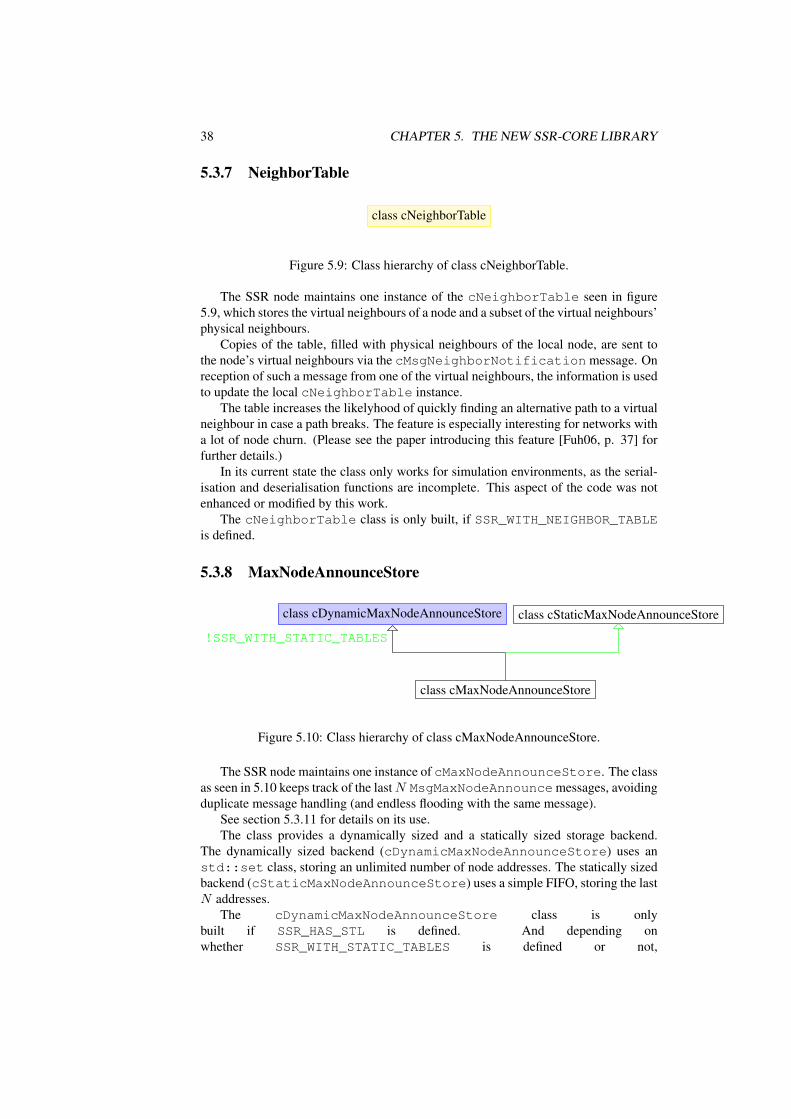
Figure 5.10: Class hierarchy of class cMaxNodeAnnounceStore.
The SSR node maintains one instance of cMaxNodeAnnounceStore. The classas seen in 5.10 keeps track of the last N MsgMaxNodeAnnouncemessages, avoidingduplicate message handling (and endless flooding with the same message).
See section 5.3.11 for details on its use.The class provides a dynamically sized and a statically sized storage backend.
The dynamically sized backend (cDynamicMaxNodeAnnounceStore) uses anstd::set class, storing an unlimited number of node addresses. The statically sizedbackend (cStaticMaxNodeAnnounceStore) uses a simple FIFO, storing the lastN addresses.
The cDynamicMaxNodeAnnounceStore class is onlybuilt if SSR_HAS_STL is defined. And depending onwhether SSR_WITH_STATIC_TABLES is defined or not,

5.3. CLASS DIAGRAMS 39
cStaticMaxNodeAnnounceStore or cDynamicMaxNodeAnnounceStoreare used as storage.
5.3.9 NicAddr
class cDynamicNicAddr class cStaticNicAddr
template class cNicAddr
typedef tNicAddr
!SSR_WITH_STATIC_TABLES
Figure 5.11: Class hierarchy of class cNicAddr.
Instances of the tNicAddr class as seen in figure 5.11 represent a physical neigh-bour’s link-layer address. Within the SSR core, these addresses are handled completelytransparently as a block of bytes and comparisons between two addresses are performedbyte by byte.
This allows the library user to hand in any kind of structure that identifies a singlephysical address. A sensible data block might be e.g. a 48 bit Ethernet MAC-addressor a 32 bit memory pointer, pointing to a more complex data structure on the heap.
The cDynamicNicAddr storage back-end uses heap memory to dynamicallystore a copy of any number of address bytes. The cStaticNicAddr storage back-end instead uses a fixed-size embedded buffer for the copy.
The cDynamicNicAddr class is only built if SSR_HAS_HEAPand SSR_HAS_EXCEPTIONS are defined. Depending on whetherSSR_WITH_STATIC_TABLES is defined or not, cStaticNicAddr orcDynamicNicAddr are used as storage.
5.3.10 PathsThe cPath class as seen in figure 5.12 stores a source route, which consists of anarray of SSR node addresses. The cWritablePath class is a sub-class that allowsthe manipulation of the stored source route and the cEmptyPath sub-class representsan empty route.
The cDynamicPath storage back-end uses heap memory to dynamically allocatememory for the list of SSR node addresses. The length of the path is not restricted. ThecStaticPath storage back-end instead uses a fixed-size array, therefore restrictingthe possible path lengths to a value defined at compile-time.
Both storage back-ends use reference counting, to avoid duplicate copies of thesame path. For cStaticPath, this is achieved by using cStaticPool, see section5.3.13.

40 CHAPTER 5. THE NEW SSR-CORE LIBRARY
class cDynamicPath class cStaticPath
template class cPath
typedef tPath template class cEmptyPath template class cWritablePath
typedef tEmptyPath typedef tWritablePath
!SSR_WITH_STATIC_TABLES
Figure 5.12: Path class hierarchy.
The cDynamicPath class is only built if SSR_HAS_HEAP andSSR_HAS_EXCEPTIONS are defined. The typedefs tPath, tWritablePath andtEmptyPath are defined to use the static or dynamic path storage depending onwhether or not SSR_WITH_STATIC_TABLES is defined.
5.3.11 MessagesThe leaf classes within the class hierarchy tree, as seen in figure 5.13, represent SSRmessages sent over the wire. The messages are either unserialised from the bit-streamusing the cMessage::ReadFromBuffer() factory method, newly constructed bythe library via new or cloned via the Clone() virtual method.
The non-leaf classes cMsgHopByHop and cMsgConnect are implementationhelpers and do not represent real SSR messages.
In case the environment provides no heap memory (i.e. SSR_HAS_HEAP is notdefined), the messages are created using the cMessagePool (which is based oncStaticPool, see section 5.3.13).
The hello message, represented by the cMsgHello class, is used to broadcast thelocal node’s existence to all physical neighbours. The message is regularly broadcastby the local node using the cEventBroadcast-based timer. On reception of such amessage, it is not forwarded to other nodes, as it only concerns direct physical neigh-bours.
The kill message, represented by the cMsgKill class, is used to indicate a node’sshutdown. It is broadcast to all physical neighbours. When receiving the message, theindicated node is removed from the interface table and the routing table. The messageis not forwarded to other nodes.
The max node announcement message, represented by thecMsgMaxNodeAnnounce class, is used by the node with the highest virtualaddress to broadcast its existence to the whole SSR network. Every node receivingthe message will first check whether it has received the same message before. If the

5.3. CLASS DIAGRAMS 41
class cMessagePool
abstract class cMessage
abstract class cMsgHopByHop
class cMsgRouteUpdate abstract class cMsgConnect
class cMsgNeighborNotification class cMsgPayload
class cMsgHello class cMsgKill class cMsgMaxNodeAnnounce
!SSR_HAS_HEAP
Figure 5.13: Message class hierarchy.
message is new, it will check whether the broadcasted information matches with itsknowledge of the virtual ring. Based on this it might possibly send updates to itsvirtual neighbours. In the end, the announcement message is broadcast to all physicalneighbours (apart from the one it originally received it from).
The neighbour notification message, represented by thecMsgNeighborNotification class, is regularly sent to both virtual neigh-bours in the virtual ring. In case the neighbour table feature is enabled, the messageincludes a copy of the local neighbour table. (See section 5.3.7 for details on neighbourtables.)
The payload message, represented by the cMsgPayload class, transports the ac-tual data from the upper layer. The class instance does not hold a copy of the payloaddata within the instance, instead only a pointer to the original data is stored. If themessage is newly created, the payload pointer points to the application’s provided databuffer. It it was received from the link-layer, the pointer points to the raw messagebuffer. If the message has the routed flag set, it is assumed that the message’s targetaddress might not refer to an existing node’s address, but instead be intended for thenode that is virtually nearest to the target address.
Route update messages, represented by the cMsgRouteUpdate class, containroute updates and always target a specific node. It is used to inform nodes about brokenlinks, so that they can update their routing tables. The message implicitly containsfreshly updated replacement routes through its source path.

42 CHAPTER 5. THE NEW SSR-CORE LIBRARY
class cNodeEnumeration
Figure 5.14: Class hierarchy of class cNodeEnumeration.
5.3.12 cNodeEnumerationThe cNodeEnumeration, as seen in figure 5.14, is used to allow node addressesfrom cRouteCache to be enumerated by users of the cRouteCache class.
5.3.13 cStaticPool
class cStaticPool
Figure 5.15: Class hierarchy of template class cStaticPool.
The cStaticPool template class, as seen in figure 5.15, provides a pool of mem-ory chunks. Each chunk is of equal size. The class only provides simple acquiring orfreeing of chunks. The memory pool is statically allocated at compile-time.
The class is used as implementation detail in cMessagePool for messages andin cStaticPath for a pool of reference counted source paths.

Chapter 6
Evaluation
The following sections detail how the modifications to the ssr-core library were verifiedand tested.
6.1 Unit testsModifications to any non-trivial piece of code need to be verified and tested thoroughlyto avoid introducing bugs. The old ssr-core implementation used a separately main-tained set of unit tests to verify some of the library components.
As the code coverage of the unit tests was very limited and the tests weren’t inte-grated into the build process, they weren’t very effective in preventing the introductionof bugs. Therefore, the test-suite is now integrated into the build tree and executed aftereach compile cycle, causing the build to fail in case one of the tests fails.
Errors within the unit tests are now reported in a format, that allows common graph-ical development environments to visibly point to the failed test. 1
The unit tests were extended to cover more major components present within thelibrary. Specifically, the following tests were added in this work:
• In suite cTestPath, the tests TestSingleHop, TestWritable,TestReverse and TestZero.
• In the newly added suite cTestRouteCache, the testsTestEmptyHasSelfRW, TestEmptyThrowsNoPathFound,TestLearnsPath, TestRemoveLink, TestPhysicalNeighbors,TestPredecessorSuccessor and TestPathTowards.
• In the newly added suite cTestBitFieldArray, the testsTestSizeCalculation, Test3And8Single, Test3And8Highest,Test3And8All, Test8And3Single, Test8And3Highest andTest8And3All.
Further tests were later added by Pengfei Di, the maintainer of the ssr-core library.According to make check-test-coverage, which uses the LTP GCOV ex-
tension2, the current code coverage remains at only about 43.5 percent.1The messages are displayed in a format that is sufficiently similar to the error output of the GNU GCC
compiler. This was verified with Eclipse.2See http://ltp.sourceforge.net/coverage/lcov.php
43

44 CHAPTER 6. EVALUATION
Although the code coverage is far from perfect, the existing unit tests helped ironout a few bugs during the ssr-core porting effort.
6.2 Automated simulation testsUnit tests, as described in the previous section and as used within the project, areexplicitly intended for the testing of classes without the interaction of other classes(and their bugs). Therefore, unit tests cannot test whether the components in the ssr-core library properly interact and whether the library correctly implements the SSRprotocol.
To achieve something close to this kind of verification, SSR network simulationsare used, based on the OMNeT++3 framework. OMNeT++ provides a simulation en-vironment that passes messages between user defined layers (figure 6.1). The environ-ment allows the definition of hosts and network topologies, the tracking of the messagesbetween the defined network layers and hosts. It also simulates the progress of time,allowing network tests spanning several hours to be simulated within seconds.
Figure 6.1: Message passing within the OMNeT++ simulation framework.
Using this framework and a simulation of a typical MAC layer allows the realis-tic modelling and full simulation of an SSR network. These types of full simulationscenarios were used to test ssr-core since the early stages of the library.
For reproducible simulations, as required for automated testing, the existing, com-plex simulation of the MAC-layer was too unpredictable. Therefore, the complex MACsimulation was reduced by Pengfei Di to a new, simple and deterministic message-passing layer. This layer is provided within the new easyOmMac framework.
One of the features of the new framework, provided by the simulated applicationcomponent, is the detailed logging of packet paths, packet run-times and similar infor-mation. Logs of known good simulation runs – using a trusted ssr-core library version– are saved as reference log files. Based on these reference log files, log differencesduring future simulation runs can be detected and reported.
The various simulation scenarios are stored in the scenario/ subdirectory, whilethe expected content of the simulation log output files are stored within the results/
3http://www.omnetpp.org/

6.3. RUNNING ON THE AVR PLATFORM 45
subdirectory. By running the simulation for each scenario and comparing the log re-sults with the matching reference log files, the simulator was turned into an automatedsimulation tester.
The simulations based on the easyOmMac predictable MAC-layer proved veryimportant for the ssr-core porting effort, as it was the only run-time integration testavailable during most of the development time. Although the simulations never showedany changes in routing behaviour, they did uncover interaction bugs or crashes withinthe library.
According to the LTP GCOV extension, the simulation scenarios cover 47.3 per-cent of the code, so more scenarios should be created to increase the code coverage.Especially error and packet-loss cases are currently untested.
6.3 Running on the AVR platformTo verify, that the ported ssr-core library actually executes on the AVR target platformand can use the basic AmbiComp software stack, the library was integrated into a testenvironment (figure 6.2).
Figure 6.2: SSR test application in the partial AmbiComp software stack.
The test environment layers on top of the AmbiComp BIOS version 1.0. To avoidintegration complexity and memory limits, it uses a custom test application instead ofthe ACVM. No interaction with any link-layer is performed. Instead, all activity ofssr-core is fed back into the test application and logged to the BIOS’ serial console.
To allow the test application to run, the ssr-core library first needed to be compiledfor the AVR platform. As GCC’s AVR port only provides very basic C++ support, twosimple libraries needed to be created: avr-libstdc++ and avr-libsupc++.
The avr-libstdc++ library serves as a very simple replacement for the missinglibstdc++. It only provides a few missing, standard C++ headers and most of themmerely wrap around standard C headers (e.g. cstring wraps around string.h).
The avr-libsupc++ library provides method stubs and definitions, that belongto the compiler side of C++ support and are absolutely necessary to link a C++ programwhen using virtual methods or certain allocation and deallocation operators.
Next, based on the fully ported ssr-core library, a cStubSsrNode class was writ-ten, sub-classing SSR::cNode. For all virtual methods the stub class logs the activity

46 CHAPTER 6. EVALUATION
and returns. The only methods implementing real functionality are the timer event han-dlers (CallMeLater() and CancelEvent()). They interact with a timer eventscheduler.
As the ACVM would normally provide the timer management, the test applicationneeded to provide that facility itsself. Therefore, cTimerEventScheduler wascreated, to queue and schedule a limited number of events. It gets repeatedly called bythe BIOS’ single timer event.
As the node and timer instances are too large for the stack, they are allocated on thefirst external SRAM page (XRAM, page 0).
Tests have shown, that the node correctly registers its timers and regularly attemptsto announce itsself to its neighbours:
XRAM: Detected 4 pages, each page 32 Kbytes largeXRAM: Creating cTimerEventSchedulerXRAM: Creating cStubSsrNodecStubSsrNode constructedCalling node initcStrubSsrNode::CallMeLater(2.520563)cStrubSsrNode::CallMeLater(1.183149)Starting timerEntering event loopcStrubSsrNode::HandleTimerEvent for event type 3cStrubSsrNode::CallMeLater(3.849298)cStrubSsrNode::HandleTimerEvent for event type 1cStrubSsrNode::BroadcastcStrubSsrNode::CallMeLater(3.895320)cStrubSsrNode::HandleTimerEvent for event type 3cStrubSsrNode::CallMeLater(4.234942)cStrubSsrNode::HandleTimerEvent for event type 1cStrubSsrNode::BroadcastcStrubSsrNode::CallMeLater(2.092654)cStrubSsrNode::HandleTimerEvent for event type 1cStrubSsrNode::BroadcastcStrubSsrNode::CallMeLater(2.505668)cStrubSsrNode::HandleTimerEvent for event type 3cStrubSsrNode::CallMeLater(3.804689)...
Any further testing would need to involve at least a second node instance, whichwould require adapting the code to at least one of the available link-layers. Due to timeconstraints, these additional efforts are not within the scope of this work.

Chapter 7
Conclusion and future work
7.1 ConclusionIn the course of this study thesis, the restrictions imposed by the AmbiComp environ-ment, regarding the integration of the ssr-core library, were determined. Approacheswere analysed to allow the library to cope with these restrictions. In the end, appro-priate approaches were chosen and implemented. This involved the removal of heapallocations, exceptions, RTTI usage and STL usage. It also involved shrinking datastructures and removing function inlining to shrink the memory and code foot-prints.
The changes were applied in such a way, that the ssr-core code-base remains fullyusable for all previous and future use-cases. This was achieved by refactoring datastorage classes and making the code configurable through compile-time options.
By improving the library’s unit test coverage and by the introduction of repro-ducible network simulation scenario tests, the library was continuously verified.
The final ssr-core implementation was tested on the target platform AVR, interact-ing with AmbiComp’s BIOS layer and performing basic operations.
Through-out the work, the library’s code was cleaned up and refactored.
7.2 Safety in the wildThe new implementation of the ssr-core library compiles, links and runs on the targettedAVR platform and for the previously existing environments (i.e. within the OmNet++simulation and on the MIPS platform). Before it is safe for usage in an environmentoutside of simulations and carefully managed nodes, at least the following issues needto be resolved.
7.2.1 Errors in constructorsAs mentioned in section 4.3.2, the cPath-based classes do not handle out-of-memory(OOM) conditions gracefully. To fix this, the Init()-approach mentioned in thatsection could be implemented. It would involve moving the actual work out of theconstructors into Init() functions. Errors would then be indicated by an appropriatereturn value and OOM conditions could be handled appropriately, e.g. by droppingpackets. Those conditions would therefore no longer cause the program to abort.
47

48 CHAPTER 7. CONCLUSION AND FUTURE WORK
7.2.2 Length limitation on source pathsThe cStaticPath class assumes that paths do not exceed a certain hop-count (i.e.length). Apart from the unsafe allocation problems mentioned in the previous section,this static length approach might conflict with regular routing. Simulation runs mighthelp to determine typical, maximum path lengths. It could also be analysed how manypaths are used at the same time within the ssr-core implementation. Based on thisinformation, useful values could be determined for the cStaticPath hop length andpool size.
7.2.3 Limited number of physical neighboursThe fixed-size interface storage table (cStaticInterfaceStore) needs a strategyfor entry replacement in case it is full. Currently, in case a new neighbours appears andthe table is full, the operation fails and the new neighbour is ignored.
Consider the following problems:
• How can network fragmentation be avoided if not all nodes within the localnetwork are known to each other? How can a consistent virtual ring be thenmaintained?
• Would it help to accept new neighbours by picking them randomly, so that hope-fully all nodes within the local network have connections to each other?
• Should nodes be prioritised before being thrown out? The priorisation could bebased on network type (to keep links between different types of networks active),activity, age or some other scheme.
• Nodes announce themselves in regular intervals, so a full interface storage tablewould regularly lead to the same overflow conditions. Should interface churn beavoided within the table?
7.2.4 Table sizes need reality checkThe table sizes chosen for various newly fixed-size structures should be verified bysimulations. Currently, most of the sizes are arbitrarily chosen, as they can’t easily bedetermined by theoretical observations.
This includes the interface table, the source path lengths and the size of the staticsource path pool.
7.3 Integration with the AmbiComp environment
7.3.1 Link-layersTo be useful for the AmbiComp environment, the SSR::cNode needs to communi-cate with other nodes. It therefore needs to have access to link-layers, so that commu-nication with other AICUs is possible.
An adapter for link-layers would need to handle support for more than one link-layer type per node, e.g. for both ethernet and bluetooth at the same time. It wouldtherefore have to multiplex/demultiplex the HandleFromNic(), SendToNic()and Broadcast() calls to and from the appropriate link-layers.

7.3. INTEGRATION WITH THE AMBICOMP ENVIRONMENT 49
7.3.2 ACVMEvent loop
As the ACVM handles the event loop, any timer management would need to interactwith the ACVM or use possibly existing timer infrastructure within it. In case theACVM provides insufficient timer handling capabilities, cTimerEventScheduler(introduced in section 6.3) could be used as a starting point.
Access to SSR functionality
The ACVM needs to gain access to the functionality provided by the ssr-core library.This can either be explicit access, by providing Java Native Interfaces for messagesending and receiving or transparently, by adapting the GAO implementation (compare[SEF08]) to make use of SSR.
Dynamic memory
As the ssr-core resides within the OS-layer and neither that layer nor the accompanyingBIOS-layer provide dynamic memory management, all dynamic memory allocationshad to be circumvented. It might be worthwhile to explore possibilities of using theACVM’s memory management facilities within the SSR.

50 CHAPTER 7. CONCLUSION AND FUTURE WORK

Appendix A
Source tree and buildenvironment
This appendix explains the layout of the library’s source files and build system. Itintroduces naming conventions for source code and code configuration.
A.1 Files and directoriesA clean checkout from the code repository will contain the following files and directo-ries:
File or directory Description/ The base directory contains all source files, in-
cluding all headers (except config.hh)./README.txt Contains information about the library and its
structure. Briefly documents how to use it./TODO Short list of open items./Makefile The central makefile. It provides short-cuts
for the actual makefiles within the compilationtarget directories.
/common.mk Library of build targets used by the compila-tion target makefiles.
/Doxyfile Configuration file for Doxygen, which is adocumentation generator.
/*.hh All C++ header files use the file name exten-sion .hh. A single header file should describea single C++ class. The base name is derivedfrom the class name.
/*.cc All C++ implementation files use the file nameextension .cc.
/*.inl All C++ inline files use the file name extension.inl. The inline files typically contain theimplementation of C++ template classes andmethods.
51

52 APPENDIX A. SOURCE TREE AND BUILD ENVIRONMENT
/cross-avr/ Each compile target has a separate directory. Itcontains a Makefile and a config.hh file.The “cross-avr” target is intended for usewithin the ACVM. The code gets cross-compiled for the AVR architecture. It is con-figured for static tables and no heap. No unittests are run.
/cross-avr/config.hh Defines a set of preprocessor symbols to con-figure the build for the “cross-avr” compile tar-get.
/cross-avr/Makefile Based on /common.mk this makefile buildsthe library for the “cross-avr” compile target.
/cross-mipsel/ Cross-compilation target for MIPS routers. Nounit tests are run. The directory contains thesame files as the /cross-avr/ directory.
/debug-linux/ Full-featured dynamic linux target with debug-ging. The unit tests are run. The directory con-tains the same files as the /cross-avr/ di-rectory.
/release-linux/ Full-featured dynamic linux target without de-bugging. The unit tests are run. The directorycontains the same files as the /cross-avr/directory.
/static-linux/ Linux build with static tables and no heap. Theunit tests are run. This allows the static codepaths used by AVR to be tested on a linux ma-chine. The directory contains the same files asthe /cross-avr/ directory.
/tests/ Directory containing the source files for theunit tests.
/tests/main.cc Contains the unit test runner./tests/Test*.cc Unit test implementation file names are pre-
fixed with “Test” by convention./tests/cppunit2junit.xsl XSL file to translate the XML produced by
CPPUnit to the XML format normally pro-duced by JUnit.
/tests/tests-common.mk Library of build targets specific to unit testbuilding. It includes /common.mk and isused by the unit test compilation target make-files.
/tests/release-linux/ Each native target has a matching build direc-tory within tests. It contains a Makefile andall compile-time generated files. This specificdirectory is for the “release-linux” target.
/tests/release-linux/Makefile Based on /tests/tests-common.mkthis makefile builds the unit tests for the“release-linux” compile target.

A.1. FILES AND DIRECTORIES 53
/tests/static-linux/ Build directory for the static-linux target.The directory contains the same files as the/tests/release-linux/ directory.
/tests/debug-linux/ Build directory for the debug-linux target.The directory contains the same files as the/tests/release-linux/ directory.
As soon as one or more targets were built, the above directories contain the follow-ing new files and directories:
File or directory Description/<target>/ This should be read as the target’s directory, i.e.
replace <target> with the name of the built tar-get (e.g. /cross-avr/).
/<target>/build_flags.mk This makefile inclusion file contains theCPP_FLAGS used to build the library. It isautomatically created by the build-system andcan be included in projects that make use of thelibrary.
/<target>/*.d All files with the .d suffix are dependency files,documenting the matching .cc file’s header de-pendencies, i.e. the build dependencies of the re-sulting object file.
/<target>/*.o All files with the .o suffix are the object files forthe matching .cc files.
/<target>/libssr-core.a The ssr-core library variant intended for staticlinking.
/<target>/libssr-core.so The ssr-core library variant intended for dynamiclinking.
/<target>/include/ssr-core/ This directory is created at build-time. Itcontains symbolic links to the actual headerfiles. By providing this directory structure,the headers can be referenced through fullyqualified #include<ssr-core/Class.hh>statements, instead of through less specific#include<Class.hh> statements.
/tests/<target>/*.d Dependency files. Same as /<target>/*.d,only for the unit tests.
/tests/<target>/*.o Object files. Same as /<target>/*.o, only forthe unit tests.
/tests/<target>/SSR-Test The executable running all unit tests./tests/<target>/SSR-Test.cppunit.xml
After running the above unit test exe-cutable, this file contains the unit test re-sults in CPPUnit XML format. Callingmake SSR-Test.junit.xml would thencreate the same information in the JUnit XMLformat. (See below.)

54 APPENDIX A. SOURCE TREE AND BUILD ENVIRONMENT
A.2 Build targetsThe following build commands are possible from the source’s root directory:
Make command Descriptionmake or make all Build the library for all build targets.make check-test-coverage Builds debug-linux and static-linux build tar-
gets and gathers code coverage for the unittests. Generates a code coverage static in thetest-coverage-html/ directory.
make clean Clean all build targets.
The following build commands are possible within a build target directory (e.g.within /debug-linux/ for the “debug-linux” build target):
Make command Descriptionmake or make all Build the library for the build target. For native
builds, i.e. non-cross-compile builds, this auto-matically triggers make run-tests as well.
make run-tests This make target only exists for non-cross-compile builds. It compiles and runs the unit tests.(It runs make within the matching unit test’s builddirectory, see below.)
make clean Cleans all build artifacts for current build-tree andthe matching unit test tree.
The following build commands are possible within a unit tests’ build directory (e.g.within /tests/debug-linux/ for the “debug-linux” unit test build):
Make command Descriptionmake or make all Builds the unit tests and runs them in case some-
thing changed (either within the tests or within thelibrary).
make run-tests Builds and runs the unit tests.make gdb-run-tests Builds the unit tests and runs them within a gdb
session.make SSR-Test.junit.xml This reads the SSR-Test.cppunit.xml file
and creates the JUnit format.make clean Cleans all build artifacts for the current unit test
build tree.

A.2. BUILD TARGETS 55

56 APPENDIX A. SOURCE TREE AND BUILD ENVIRONMENT

Bibliography
[CF05] Curt Cramer and Thomas Fuhrmann. Isprp: A message-efficient protocolfor initializing structured p2p networks. In Proceedings of the 24th IEEEInternational Performance, Computing, and Communications Conference(IPCCC), pages 365–370, Phoenix, AZ, April 7–9 2005.
[DEF08] Pengfei Di, Johannes Eickhold, and Thomas Fuhrmann. Linyphi: cre-ating ipv6 mesh networks with ssr. Concurr. Comput. : Pract. Exper.,20(6):675–691, 2008.
[EFS+08] Johannes Eickhold, Thomas Fuhrmann, Bjoern Saballus, Sven Schlender,and Thomas Suchy. Ambicomp: A platform for distributed execution ofjava programs on embedded systems by offering a single system image. InAmI-Blocks’08, Workshop at the European Conference on Ambient Intel-ligence 2008, Nuremberg, Germany, 2008.
[FDKC06] Thomas Fuhrmann, Pengfei Di, Kendy Kutzner, and Curt Cramer. Push-ing chord into the underlay: Scalable routing for hybrid manets. InternerBericht 2006-12, Fakultat fur Informatik, Universitat Karlsruhe, June 212006.
[Fuh05] Thomas Fuhrmann. Scalable routing for networked sensors and actua-tors. In Proceedings of the Second Annual IEEE Communications SocietyConference on Sensor and Ad Hoc Communications and Networks, pages240–251, September 2005.
[Fuh06] T. Fuhrmann. Scalable routing in sensor actuator networks with churn.Sensor and Ad Hoc Communications and Networks, 2006. SECON ’06.2006 3rd Annual IEEE Communications Society on, 1:30–39, Sept. 2006.
[SEF08] Bjoern Saballus, Johannes Eickhold, and Thomas Fuhrmann. Global ac-cessible objects (gaos) in the ambicomp distributed java virtual machine.In Proceedings of the Second International Conference on Sensor Tech-nologies and Applications (SENSORCOMM 2008), Cap Esterel, France,August 25 – 31, 2008. IEEE Computer Society.
[SMK+01] Ion Stoica, Robert Morris, David Karger, M. Frans Kaashoek, and HariBalakrishnan. Chord: A scalable peer-to-peer lookup service for inter-net applications. In SIGCOMM ’01: Proceedings of the 2001 conferenceon Applications, technologies, architectures, and protocols for computercommunications, pages 149–160, New York, NY, USA, 2001. ACM.
57


![Assisting with Scalable Scalable Vector Graphics and ... · SVG Scalable Vector Graphics [6] SSVG Scalable Scalable Vector Graphics [10] LWA Live Website Annotate [See Section 4]](https://img.pdfslide.us/doc/110x75/5fdccc690a10ab2c1e74ae97/assisting-with-scalable-scalable-vector-graphics-and-svg-scalable-vector-graphics.jpg)